Version 1.3
Thank you for choosing the ELEGOO Product!
Upon receiving your product, please check that the device is in good condition
and all accessories are included. If you encounter any issues during installation,
operation, or maintenance, please contact the ELEGOO after-sales team through
the official channels below for professional support:
1. Visit our dedicated support page: https://www.elegoo.com/pages/contact-sup-
port. (We recommend copying the link and opening it in your browser.)
2. Scan the QR code below for one-on-one assistance.
(Note: To ensure optimal performance, each ELEGOO product undergoes rigor-
ous printing tests before shipping. Minor surface scratches may be visible upon
delivery; this is normal and will not affect functionality. )

1. Do not place the printer in highly vibrating or unstable environment, as machine
vibrations can affect print quality.
2. Do not touch the nozzle or heated bed while the printer is in operation to avoid
burns and personal injury from high temperatures.
3. After printing, promptly utilize the residual heat in the nozzle to effectively clean
the filament residue using a suitable tool. Avoid direct contact with the nozzle to
prevent potential burns.
4. When printing low-temperature filaments such as PLA and flexible filaments,
please remove the glass top cover.
5. We recommend using ELEGOO's slicing software to ensure the proper
functioning of the machine and achieve optimal printing results.
6. Perform regular maintenance on the printer by cleaning the machine body with
a dry cloth to remove dust and any sticky filament residue. Ensure the printer is
powered off before cleaning.
7. Regularly check and clean the printer's cooling fans to prevent debris buildup
and extend their lifespan.
8. Be cautious of the machine’s high-speed moving parts to avoid any potential
pinch hazards.
9. The Z-axis of the machine utilizes lead screws for its moving parts. Apply
lubricating oil as needed to ensure smooth movement.
10. Children must be supervised by adults when using the machine to avoid
personal injury.
11. In case of an emergency, directly turn off the power.
12. Ensure the machine is properly grounded for safe operation. Failure to properly
ground or neglecting to ground the machine can increase the risk of electrical
leakage.
13. If the machine is not in use for an extended period, please turn off the power
and unplug the power cord.
NOTES
Contents
Machine Parameters
Component Introduction
Accessory Specification
Machine Setup & Installation
Screen Operation Instruction
First Print
Filament Replacement
Slicing Software
LAN (Network) Printing
Mainboard Circuit Wiring Diagram
1
2
3
4
6
8
9
10
12
13
Machine Parameters
Printer Specifications
Operating Temperature Specifications
Software Specifications
Power Supply Specifications
Physical Specifications
Printer Type: FDM (Fused Deposition Modeling)
Maximum Build Volume: 256*256*256(mm³)
Print Precision: ±0.1mm
Nozzle Diameter: Standard (0.4mm)
Print Speed: ≤500mm/s
Ambient Environment Temperature: 5°C~40°C
Slicer Software: ELEGOO Slicer (recommended)
Input File Format: STL, OBJ, 3MF, STP
Output File Format: G-code
Interface: USB Drive, Wi-Fi
Input Power: AC 100-240V; 50/60Hz
Rated Power: 1100W@220V 350W@110V
Machine Size: 398*404*490mm
Net Weight: 17.5kg
1
Maximum Temperature of Nozzle: 320°C
Maximum Temperature of Heated Bed: 110°C
Component Introduction
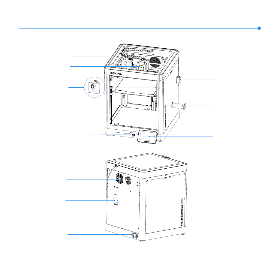
Air Filter
Filament Detection
Sensor (Filament
Detector)
Filament Spool
Holder
Touch Screen
Chamber Camera
Printhead
USB Drive Port
Filament Inlet
Power Socket
Excess Chute
2
Auxiliary Part
Cooling Fan
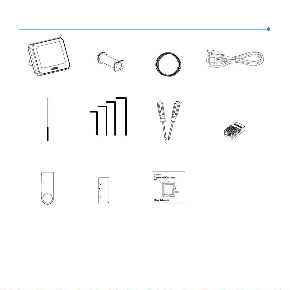
Accessory Specification
3
Touch Screen
Unclogging
Pin Tool
Spool Holder
Power Cord
(1.5/2.0/2.5/3.0mm)
Allen Wrench
USB Drive
Screwdriver
Filament Sample
User Manual
Spare Heatbed
Nozzle Wiper
Scraper Blade
Version 1.3
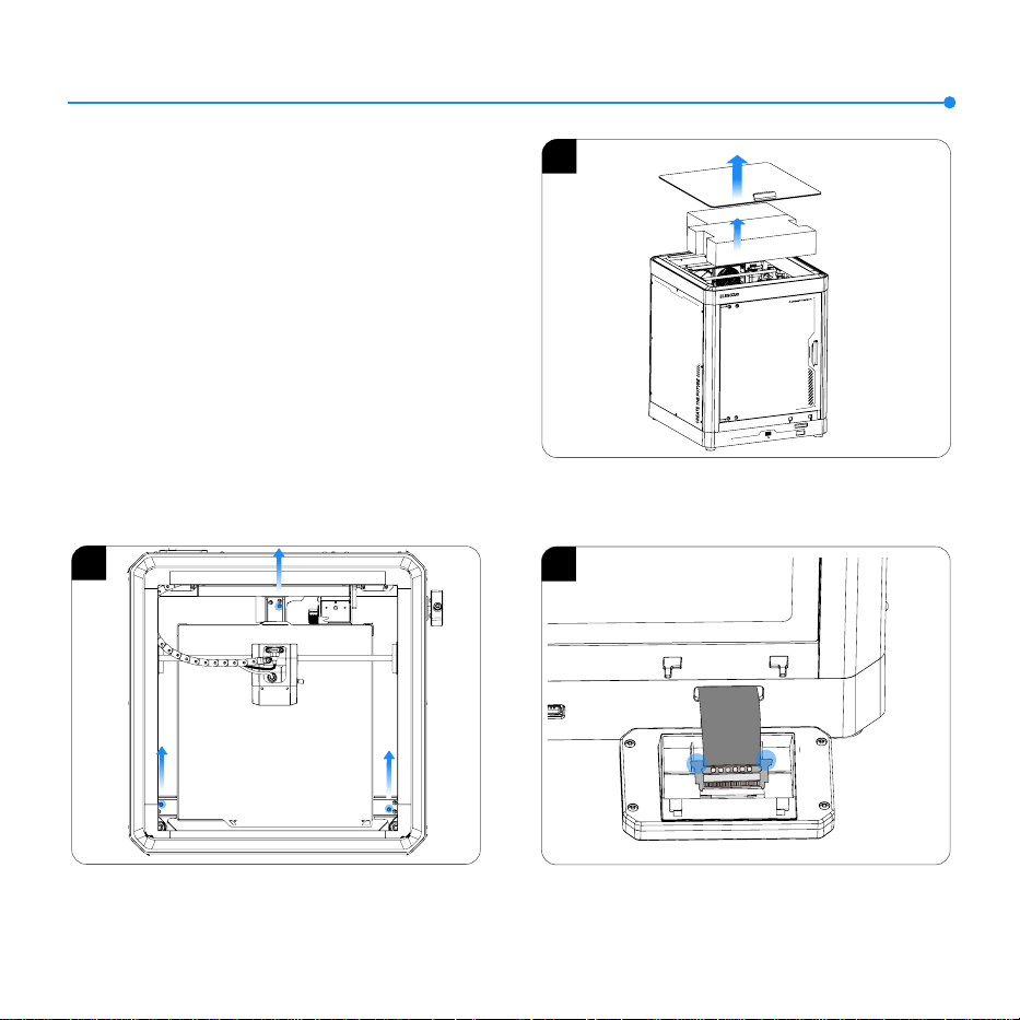
1. Take out the foam and tool kit from the printer.
2. Unlock the heated bed and use an Allen wrench to remove the
three screws in the picture.
3. Insert the ribbon cable into the port by pressing the terminal
as pictured. Make sure the gold contacts on the ribbon cable
face upwards.
2
3
4
Machine Setup & Installation
Scan to access tutorials
1
Centauri Car bo
n
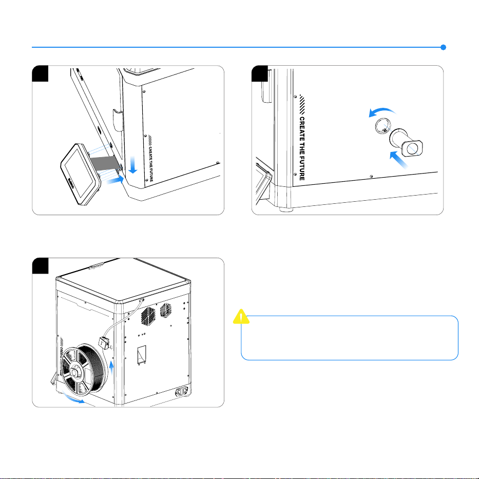
Machine Setup & Installation
5
4. Install the screen into the corresponding slot on the printer
and push it down to lock it in place.
5. Mount the spool holder onto the hole on the right side of the
machine and secure it by turning counterclockwise.
6. Load the filament by inserting one end into the filament detector
and pushing it forward until it reaches its maximum position.
5
4
6
Important note: If you have disassembled machine
components such as the nozzle assembly or build
platform, make sure to re-level the platform before
printing.
Centauri Carbon
Screen Operation Instruction
1
2
3
4
1. Language Selection 2. Follow the on-screen prompt to remove the three fixed screws
of the build platform.
3. Ensure the printer chamber is free from foreign objects, then
click “Confirm” to proceed.
4. Enter the initial self-check process. Vibrations and noises
during the self-check are normal.
6
Screen Operation Instruction
5
7
6. Self- check completed. Click “Confirm” to proceed.
6
5. Do not tap or shake the machine during the self-check process
to avoid error prompts.
Note: Ensure to recalibrate the printing platform
before each print when switching sides on the
double-sided textured flexible plate.
First Print
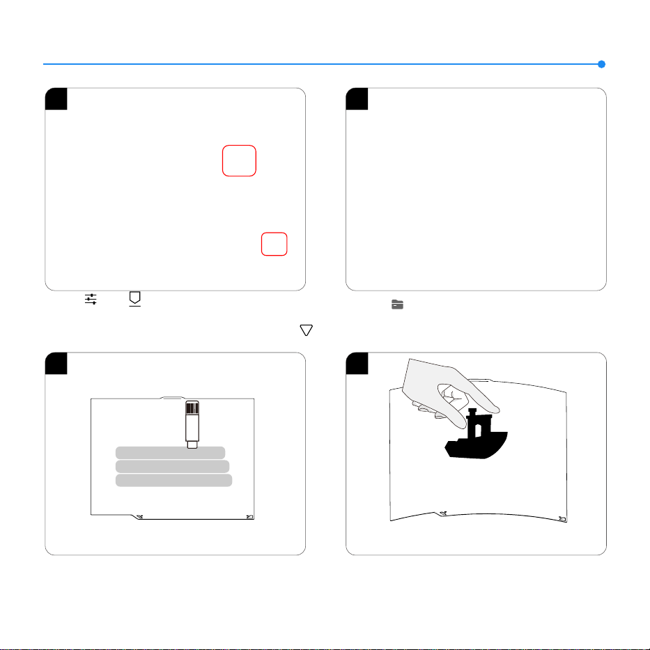
1. Click【 】- 【 】to set the nozzle temperature to
the suitable temperature for the lament (e.g., 220℃ for PLA).
Wait for the temperature to reach the set value, then click 【 】
repeatedly until the lament stas extruding from the nozzle.
2. Click 【 】 - 【Local】 to select a model for test printing.
(Tip: Long press to import print files from your USB drive to local
storage.)
1
2
8
3 4
4. After the printed model cools down, detach the flexible build
plate together with the model from the device. Bend the plate
slightly to separate the model from it (avoid overbending to
prevent deformation).
3. If the adhesion of the build plate decreases after prolonged
use, you can apply solid glue or use platform adhesive spray to
enhance the first-layer adhesion of the model, or replace the
build plate.
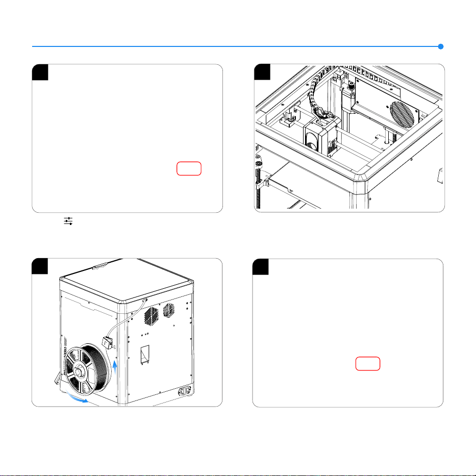
4. Click “Load” and wait for the nozzle to heat up. Once the
nozzle reaches the preset temperature , it will start the filament
loading process.
Filament Replacement
1
2. After unloading is complete, extract the old filament from the
tube and replace it with a new one.
1. Click 【 】 and switch to the Extruder option. Click
“Unload” and wait for the machine to complete the unloading
process.
9
3. Load the filament by inserting one end into the filament detector
and pushing it forward until it reaches its maximum position.
4
2
3
Centauri Carbon

Slicing Software
The included USB drive contains slicing software for installation and use.
* Select your printer model before starting the slicing process.
10

Slicing Software
11
1. Importing model for slicing: You can simply drag and drop the model file into the slicing software or click “File” in the top
left corner and select “Import.”
2. Exporting G-code file: You can use the web interface to send the generated G-code file directly to the printer for online
printing or save it to a USB drive for offline printing.
LAN (Network) Printing
12
2. Connect your computer and printer to the same local area network (LAN). Open your browser and enter the printer's IP address in the
address bar to access the backend management. Utilize the web interface to monitor the printing progress and pause/stop the print as
needed.
*Upload G-code files for printing.
1. The device supports Wi-Fi connection. Go to the
“Network” interface, establish a successful connection, and
check the IP address on the screen (refer to the image on
the right).
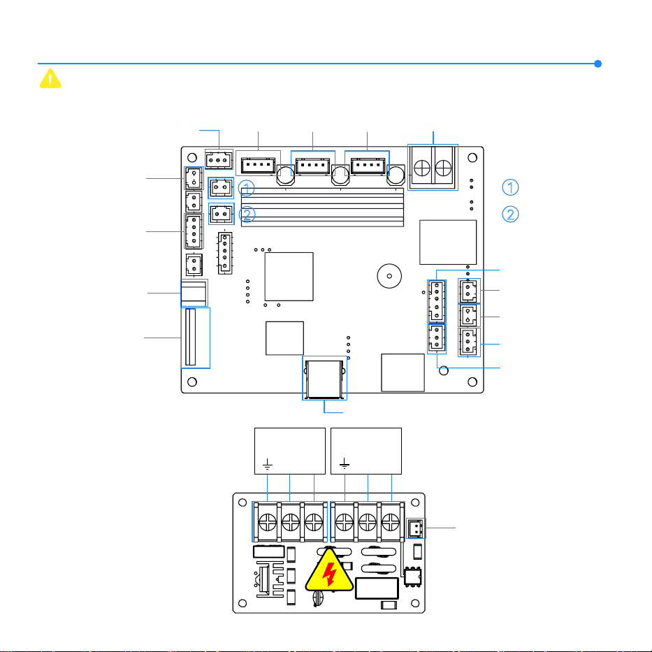
Mainboard Circuit Wiring Diagram
Type-C Interface
(24V)
Screen Ribbon
Cable Interface
Chamber Camera
Chamber
Temperature
Filament Detector
Z-Axis
Motor
Y-Axis
Motor
X-Axis
Motor
USB Drive Port
Leveling Module
Heated Bed Temperature
Heated Bed Control
Interface
Mainboard Fan
Z-Axis Optical
Limit Switch
1
2
1
Auxiliary Part
Cooling Fan
2
Case Fan
13
AC Power
Output
Heated Bed
Control Signal
L N
LN
AC Power
Input
24V Power
Input Interface
Type-C Inteace (24V): It is strictly prohibited to directly connect this po to a computer
or external devices, as it may result in damage.
+
-

Warranty Statement
ELEGOO printers are covered by a warranty from the date of receipt. Warranty periods for different
components may vary. For more details, please visit our website
(https://www.elegoo.com/pages/refund-policy).
The free warranty does NOT include problems caused by self-disassembly and improper use, and
wear and tear of the machine housing, etc.
After-sales service registration card
Date of purchase:
Printer:
Place of purchase:
Contact:
Phone number:
Address:
S/N:
Fault description:
ELEGOO official website: www.elegoo.com
Happy Printing!