Remote controller
GENERAL INFORMATION
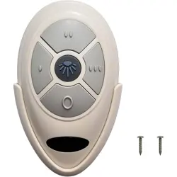
This remote controller is designed to separately control your ceiling fan speed and light brightness.
There are four buttons (HI, MED, LOW, OFF) to control the speed of the fan and off.
The light dimmer button will control the light brightness dimmer and off.
The Blue indicator on the transmitter will be on when one of the five buttons is pressed.
This is not a set, it is a FAN-35T1 handheld remote only, not include a receiver or 12V battery.
This remote control not have Reverse or UP/DOWN button.
This remote works with FAN28R/FAN18R receiver(303.9MHz).
INSTRUCTION OF INSTALLATION AND OPERATION
1.SETTING THE CODES
This unit has 16 different code combinations.
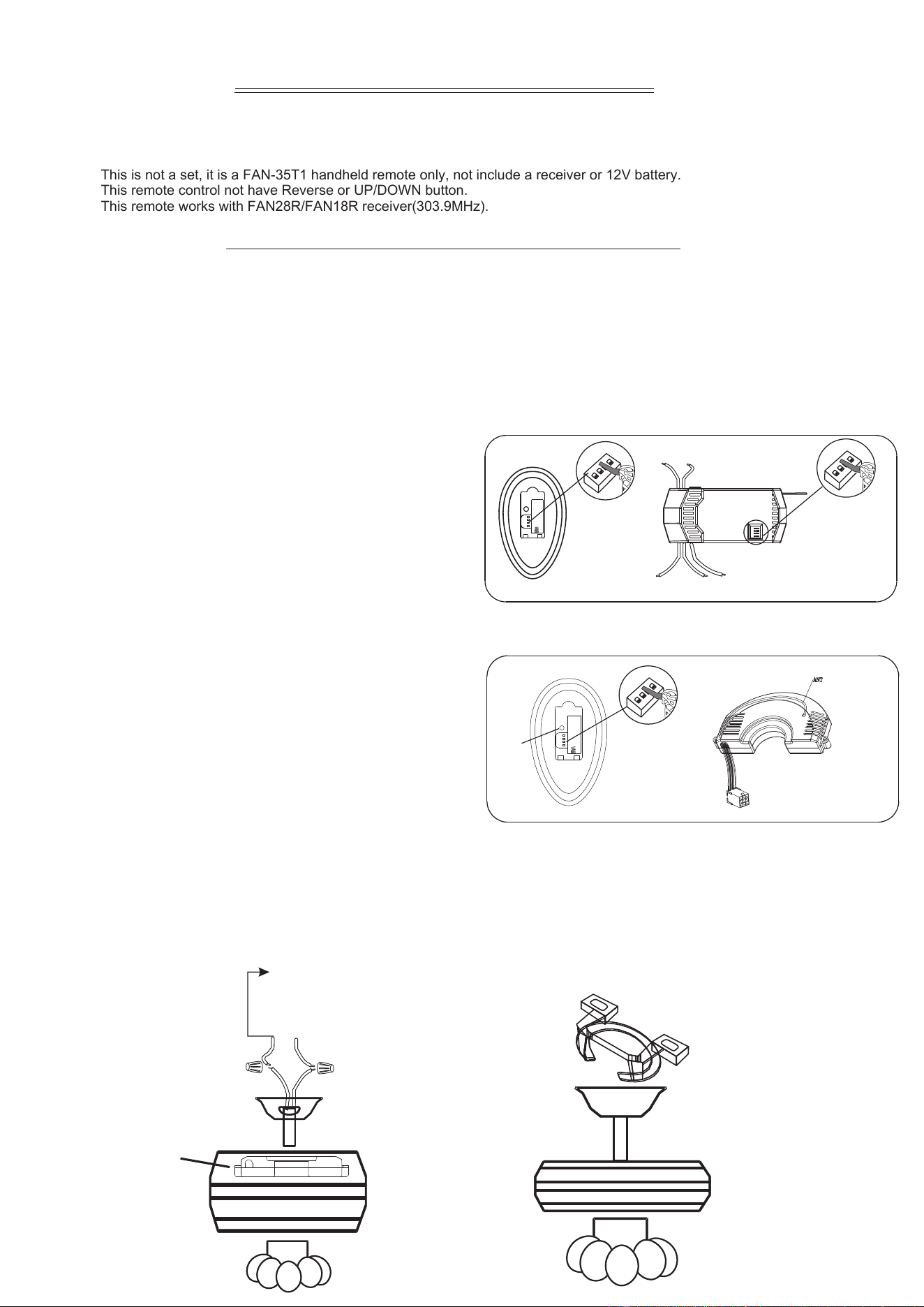
(1). If the receiver have code switches (such as model:FAN18R, FAN28R), follow these steps to set up the remote control:
A. Setting the codes on the remote:
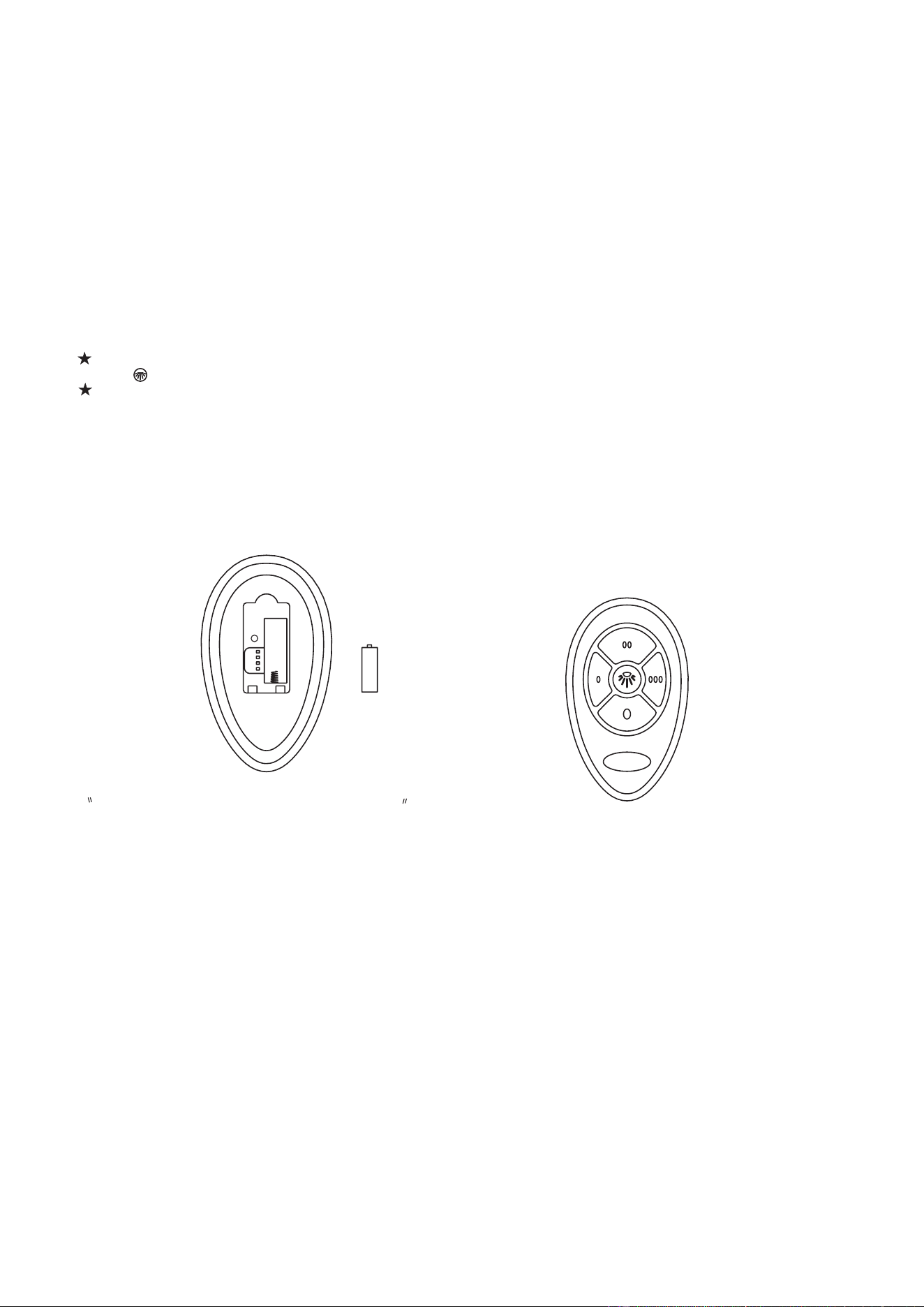
a. Remove battery cover. Press firmly on the arrow and slide battery cover off.
b. Slide code switches to your choice of ON or OFF position. Factory setting is all ON. It is not recommended to use the
default setting. Use a small screwdriver or ball point pen to slide firmly to your choice of ON or OFF position(FIG.1).
B. Setting the codes on the receiver: Slide code switches to the same position as your remote. (FIG.2)
A. Safety precautions:
WARNING: HIGH VOLTAGE! Disconnect power by
removing fuse or switching off circuit breaker.
Do not use with other solid state fans.
Electrical wire must meet all local and national
electrical code requirements.
Supply for fan must be 110/120 volt, 60Hz. Maximum
fan motor amps: 1.0, Maximum down light watts: 240
incandescent and ballast.
Otherwise power can cause serious injury or death.
B. Installing receiver in fan:
a. Remove power from the circuit.
b. Remove ceiling fan canopy from the mounting
bracket.
c. Disconnect existing wiring between ceiling fan and
Supply in electrical junction box.
d. Make connections as follows, using the wire nuts
supplied:
Use wire connecting nuts supplied with the fan
(FIG.4)
FROM POWER SOURCE
AC 110/120 VOLT 60Hz
3.5AMPS.
CONNECT TO
Green fan wire ....Bare supply wire
Red/Black receiver wire(AC IN L) .... Black supply wire
White receiver wire(AC IN N) ....White supply wire
White receiver wire(TO MOTOR N) ....White fan wire
Black receiver wire(TO MOTOR L) ....Black fan wire
Blue receiver wire( LIGHT) ....Blue light wire
Model FAN30R-240W
CANOPY
CANOPY
(FIG.5)
RECEIVER
CODE
SWITCHES
(FIG.3)
ON
2
3
4
1
ON
LEARN
RECEIVER
2. INSTALLING RECEIVER IN CEILING FAN
ACN
ACL
ANT
COM
FAN
LIGHT
CODE
SWITCHES
(FIG.1)
(FIG.2)
SWITCHES
CODE
ON
2
3
4
1
ON
ON
2
3
4
1
ON
INPUT
OUTPUT
RECEIVER
FCC ID : L3HFA N35T1
LEA RN
Model FAN28R-240W
(2). If your receiver is FAN30R, do not need to set the codes
on the receiver. Please follow these steps to pair your remote
and the receiver:
LEA RN
FCC ID : L3HFA N35T1
A. The receiver will be in learning state within 30 seconds
after the fan is powered on.
B. Keep pressing the button ( the HI/MED/LO/OFF/DIMMER
button or the LEARN key inside the battery slot) in excess of
3 second the remote becomes a LEARN status.
C. The fan light will flash three times after the receiver is
successfully paired, if not, please repeat the above steps.
(NOT INCLUDE)
Model #FAN-35T1, #FAN28R FAN-35T1
EN DIM241121
NOTICE !
Your ceiling fan and light kit assembly must meet the following requirements:
1. Do not use with other solid state fans.
2. Electrical rating: 120v 60Hz 3.5A
MAX. Motor amps: 1.0
MAX. Light watts: 240-(incandescent and ballast)
WARNING
TO REDUCE THE RISK OF SHOCK, THIS FAN MUST BE INSTALLED WITH A WALL CONTROL/SWITCH.
NOTE: THE MANUFACTURER IS NOT RESPONSIBLE FOR ANY RADIO OR TV INTERFERENCE CAUSED
BY UNAUTHORIZED MODIFICATIONS TO THIS EQUIPMENT. SUCH MODIFICATIONS COULD VOID THE
USER'S AUTHORITY TO OPERATE THE EQUIPMENT.
If other fans or supply wires are different color, have this unit installed by qualified licensed electrician.
e. Push all connected wires up into junction box.
g. Reinstall the canopy on the mounting bracket.
h. Restore power.
3. OPERATING TRANSMITTER:
A. Install 23A 12 volt battery(not included). (To prevent damage to transmitter, remove the battery if not used for a long time).
B. Store the transmitter away from excessive heat or humidity.
C. This remote control unit is equipped with 16 code combinations. In order to prevent possible interference from or to other
remote units such as garage door openers, car alarm or security system. If you find that your fan and light kit go on and off
without using your remote control, simply change the code combination in your transmitter .
D. Operating the buttons on the panel of the transmitter.
HI key -for fan high speed.
MED key-for fan medium speed.
LOW key-for fan low speed.
OFF key-for fan off.
LIGHT key-for light brightness .
The light function is controlled by pressing the LIGHT key down to increase or decrease light.
Tap key quickly to turn light off or on.
Keep pressing the button in excess of 0.7 second and it becomes a dimmer, the light varies cyclically in 0.8 second.
The receiver can remember the last status of the light brightness when the light was switched, so that it can
resume to adjust the light brightness.
FCC Statement:
This device is in conformance with Part 15 of the FCC Rules and Regulations for Information Technology
Equipment. Operation of this product is subject to the following two conditions:
This device may not cause harmful interference, and (2) this
device must accept any interference received,
including interf
erence that may cause undesired operation.
YOUR REMOTE NOW HAS FULL CONTROL OF THE FAN AND LIGHT.
OPERATION DISTANCE 20 FEET
TRANSMITTER
MODEL:
FAN-35T1
Optional Wall Mounting for Transmitter Holder
Place in accessible area of your home, and screw the
transmitter holder into wall using the two screws
provided, slide hand unit into holder.
4. TROUBLE SHOOTING GUIDE
1. Fails to operate
a. Power to receiver ?
b. Receiver wired correctly ?
c. Fan manual speed control in highest position ?
d. Light kit switch turned on ?
e. Good battery in the transmitter ?
f. Code set at exact same positions in both transmitter and receiver ?
23A 12V
FCC ID: L3HFAN35T1
2. Won't operate at distance
If transmitter operates fan/light kit when up close, but not at 20 feet away.
Try placing the brown antenna wire higher, up through ceiling/outside the junction box.
LEARN
A23 12V Battery
(NOT INCLUDE)
Model #FAN-35T1, #FAN28R FAN-35T1
EN DIM241121