USE AND CARE GUIDE
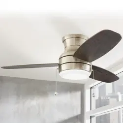
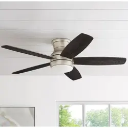
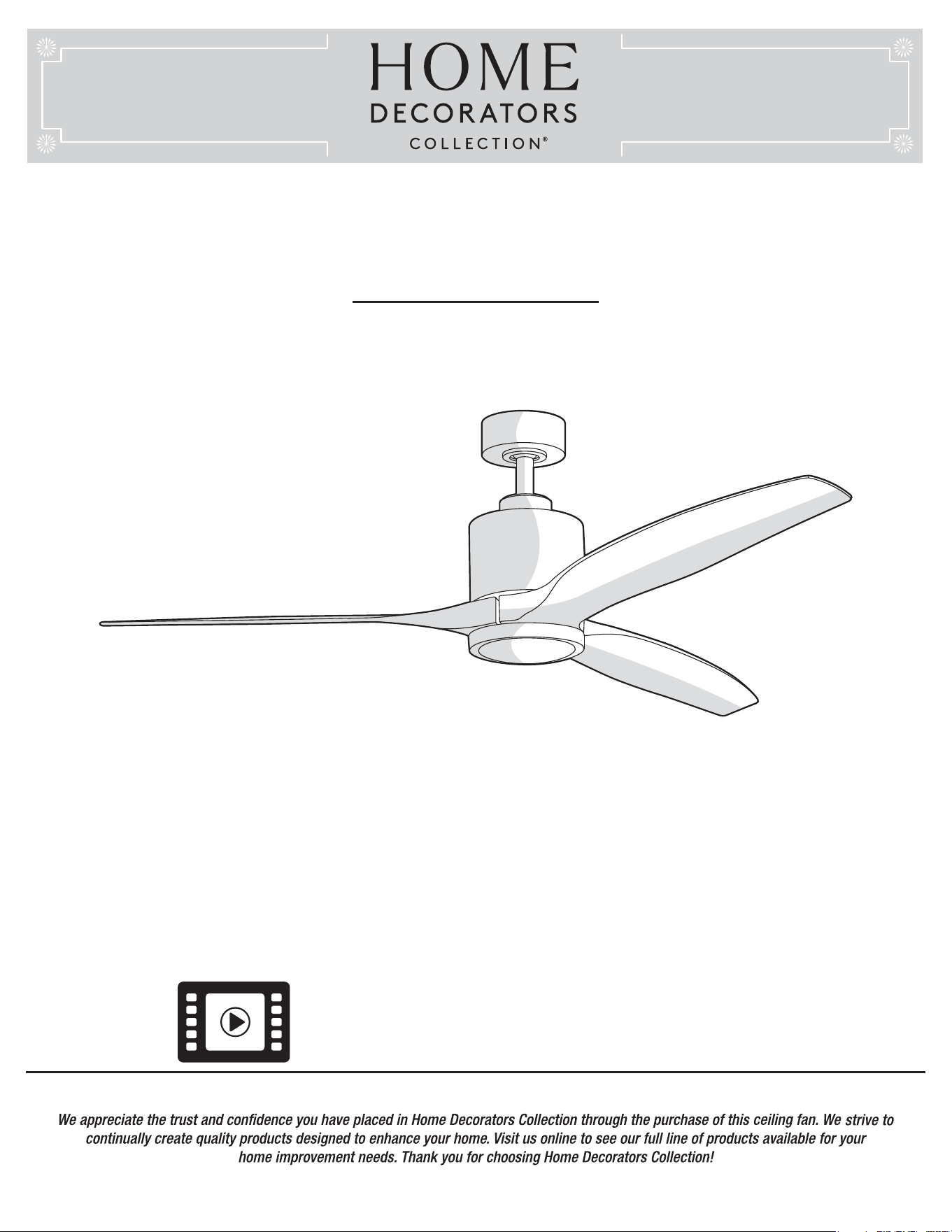
TRIPLEX 60 IN. CEILING FAN
Item #1003 823 860
#1003 823 861
#1003 823 859
Model #
YG749-BN
#
YG749-BRB
#
YG749-PN
THANK YOU
THANK YOU
Questions, problems, missing parts? Before returning to the store,
call Home Decorators Collection Customer Service
8 a.m. - 7 p.m., EST, Monday-Friday, 9 a.m. - 6 p.m., EST Saturday
1-800-986-3460
HOMEDEPOT.COM/HOMEDECORATORS
Visual instruction of how to install this fan:
Visit www.homedepot.com and enter either the Item or Model number to nd
this fan and click the link of visual instruction in the product overview section.
Operation ......................................................................
Preparing the Transmitter ......................................................
Learning Process ...................................................................
Operating Your Fan and Remote Control ...............................
Warm/Cool Weather Operating Instructions ...........................
Care and Cleaning .......................................................
Troubleshooting ..........................................................
Service Parts ...............................................................
16
16
16
18
19
20
20
22
Table of Contents
2
Table of Contents ..........................................................
Safety Information .........................................................
Warranty .........................................................................
Pre-Installation ..............................................................
Tools Required .........................................................................
Hardware Included ..................................................................
Package Contents ....................................................................
Dual Mounting Instructions ......................................................
Installation .....................................................................
Assembly ........................................................................
Standard Ceiling Mounting .......................................................
Close-to-Ceiling Mounting .....................................................
Hanging the Fan ....................................................................
Attaching the Fan Blades .......................................................
Installing the Light Kit ............................................................
2
3
4
4
4
4
5
6
7
8
9
9
10
11
14
15
READ AND SAVE THESE INSTRUCTIONS
Safety Information
3
HOMEDEPOT.COM/HOMEDECORATORS
Please contact 1-800-986-3460 for further assistance.
WARNING: To reduce the risk of electric shock, this fan
must be installed with an isolating wall control/switch.
WARNING: To reduce the risk of personal injury, do not
bend the blade arms (also referred to as anges), when
installing the brackets, balancing the blades or cleaning the
fan.
WARNING: Do not insert foreign objects between rotating
fan blades.
WARNING: To reduce the risk of re, electric shock or
personal injury, mount the fan to the outlet box marked
acceptable for fan support with the screws provided with the
outlet box.
CAUTION: To reduce the risk of personal injury, use only
the screws provided with the outlet box.
1. To reduce the risk of electric shock, ensure electricity has
been turned off at the circuit breaker or fuse box before
beginning.
2. All wiring must be in accordance with the National Electrical
Code “ANSI/NFPA 70-1999” and local electrical codes.
Electrical installation should be performed by a qualied
licensed electrician.
3. The outlet box and support structure must be securely
mounted and capable of reliably supporting a minimum of 35
lbs (15.9 kg) or less. Use only UL-listed outlet boxes marked
“FOR FAN SUPPORT.”
4. The fan must be mounted with a minimum of 7 ft. (2.1m)
clearance from the trailing edge of the blades to the oor.
5. Avoid placing objects in the path of the blades.
6. To avoid personal injury or damage to the fan and other
items, be cautious when working around or cleaning the fan.
7. Do not use water or detergents when cleaning the fan or fan
blades. A dry dust cloth or lightly dampened cloth will be
suitable for most cleaning.
8. After making electrical connections, spliced conductors
should be turned upward and pushed carefully up into the
outlet box. The wires should be spread apart with the
grounded conductor and the equipment-grounding conductor
on one side of the outlet box and ungrounded conductor on
the other side of the outlet box.
9. All setscrews must be checked and retightened where
necessary before installation.
10. Suitable for use with solid-state speed control (RH786NRW
only).
11. This device complies with part 15 of the FCC Rules. Operation
is subject to the following two conditions: (1) This device may
not cause harmful interference, and (2) this device must
accept any interference received, including interference that
may cause undesired operation.
WARNING: Changes or modications to this unit not
expressly approved by the party responsible for compliance
could void the user's authority to operate the equipment.
NOTE: This equipment has been tested and found to comply
with the limits for a Class B digital device, pursuant to Part 15
of the FCC Rules. These limits are designed to provide
reasonable protection against harmful interference in a
residential installation. This equipment generates, uses and
can radiate radio frequency energy and, if not installed and
used in accordance with the instructions, may cause harmful
interference to radio communications.
However, there is no guarantee that interference will not occur
in a particular installation. If this equipment does cause harmful
interference to radio or television reception, which can be
determined by turning the equipment off and on, the user is
encouraged to try to correct the interference by one or more of
the following measures:
- Reorient or relocate the receiving antenna.
- Increase the separation between the equipment and receiver.
- Connect the equipment into an outlet on a circuit different from
that to which the receiver is connected.
- Consult the dealer or an experienced radio/TV technician for
help.
The following responsible party designated in FCC §2.909 is
responsible for this declaration:
Model Number: YG749-BN, YG749-BRB, YG749-PN
Company Name: TAL INTERNATIONAL CORPORATION
Company Address: 2919 E. Philadelphia St., Ontario, CA 91761, U.S.A.
Full Name: James Lai Title: Manager
Telephone Number: (909) 923-2888 Fax: (909) 923-8337
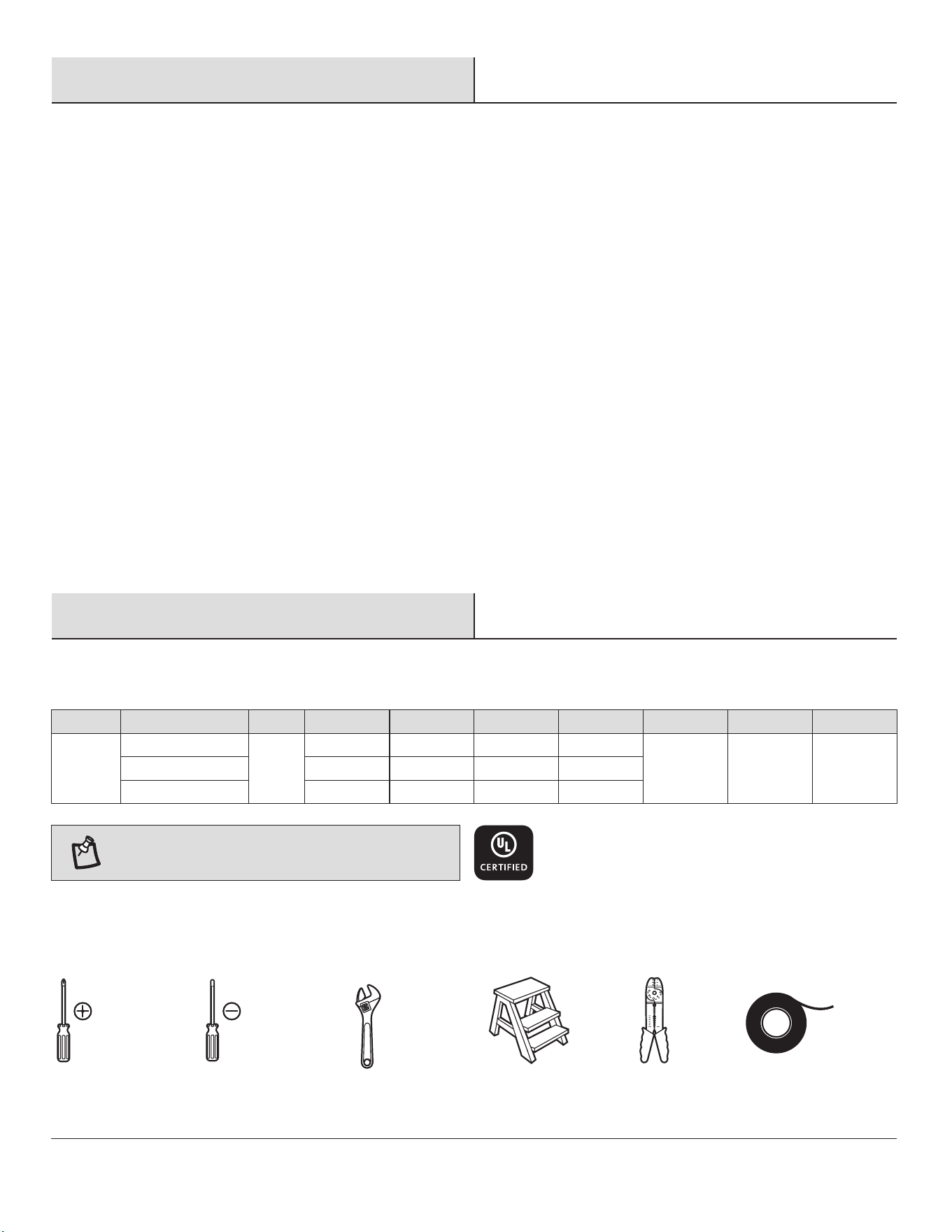
SPECIFICATIONS
SPECIFICATIONS
NOTE: These are approximate measures. They do not
include amps and wattage used by the light kit.
Warranty
4
Pre-InstallationPre-Installation
60 in.
Fan size
Fan size
Watts
Watts
RPM
RPM
CFM
CFM
Amps
Amps
2.23 cu. ft.
N.W.
N.W.
G.W.
G.W.
C.F.
C.F.
0.05
0.12
0.35
2.25
7.30
24.68
50
100
150
2245
4555
7245
6.4 kg
(14.08 lbs.)
7.72 kg
(16.98 lbs.)
Low (Speed 1)
Medium (Speed 5)
High (Speed 9)
120
Speed
Speed
Volts
Volts
The manufacturer warrants the fan motor to be free from defects in workmanship and material present at time of shipment from the
factory for a period of lifetime after the date of purchase by the original purchaser. The manufacturer warrants the light kit (excluding any
glass), to be free from defects in workmanship and material present at time of shipment from the factory for a period of ve years after
the date of purchase by the original purchaser. The manufacturer also warrants that all other fan parts, excluding any glass or acrylic
blades, to be free from defects in workmanship and material at the time of shipment from the factory for a period of two years after the
date of purchase by the original purchaser. We agree to correct such defects without charge or at our option replace with a comparable or
superior model if the product is returned. To obtain warranty service, you must present a copy of the receipt as proof of purchase. All
costs of removing and reinstalling the product are your responsibility. Damage to any part such as by accident, misuse, improper
installation or by afxing any accessories, is not covered by this warranty. Because of varying climatic conditions this warranty does not
cover any changes in brass nish, including rusting, pitting, corroding, tarnishing or peeling. Brass nishes of this type give the longest
useful life when protected from varying weather conditions. A certain amount of “wobble” is normal and should not be considered a
defect. Servicing performed by unauthorized persons shall render the warranty invalid. There is no other express warranty. We hereby
disclaim any and all warranties, including but not limited to those of merchantability and tness for a particular purpose to the extent
permitted by law. The duration of any implied warranty which cannot be disclaimed is limited to the time period as specied in the
express warranty. Some states do not allow limitation on how long an implied warranty lasts, so the above limitation may not apply to
you. The retailer shall not be liable for incidental, consequential, or special damages arising out of or in connection with product use or
performance except as may otherwise be accorded by law. Some states do not allow the exclusion of incidental or consequential
damages, so the above exclusion or limitation may not apply to you. This warranty gives specic legal rights, and you may also have other
rights which vary from state to state. This warranty supersedes all prior warranties. Shipping costs for any return of product as part of a
claim on the warranty must be paid by the customer.
Contact the Customer Service Team at 1-800-986-3460 or visit www.HOMEDEPOT.COM/HOMEDECORATORS
TOOLS REQUIRED
TOOLS REQUIRED
Phillips
screwdriver
Flat blade
screwdriver
Step
ladder
Wire
stripper
Electrical
tape
Adjustable
wrench
Pre-Installation (continued)
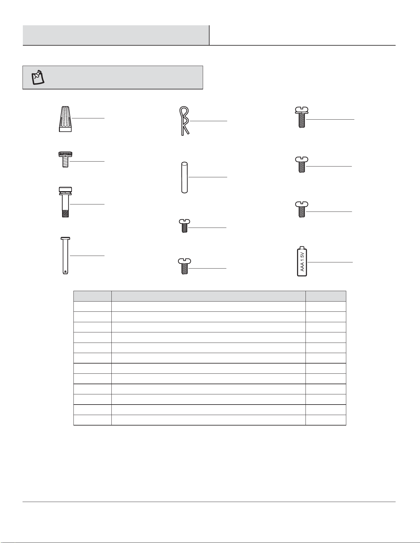
HARDWARE INCLUDED
HARDWARE INCLUDED
NOTE: Hardware not shown to actual size.
AA
BB
CC
DD
EE
FF
GG
HH
II
JJ
KK
LL
Plastic wire nut
Canopy mounting screw with lock washer (preassembled)
Blade screw with lock washer and metal washer
Clevis pin (preassembled)
Cotter pin (preassembled)
Cross pin (preassembled)
Setscrew (preassembled)
Collar setscrew (preassembled)
Collar mounting screw with lock washer (preassembled)
Light kit mounting plate screw (preassembled)
Light kit mounting screw (preassembled)
1.5V AAA battery
Part
Part
Description
Description
3
4
7
1
1
1
1
2
6
3
3
2
Quantity
Quantity
5
HOMEDEPOT.COM/HOMEDECORATORS
Please contact 1-800-986-3460 for further assistance.
AA
BB
CC
DD
FF
EE
GG
HH
JJ
II
KK
LL
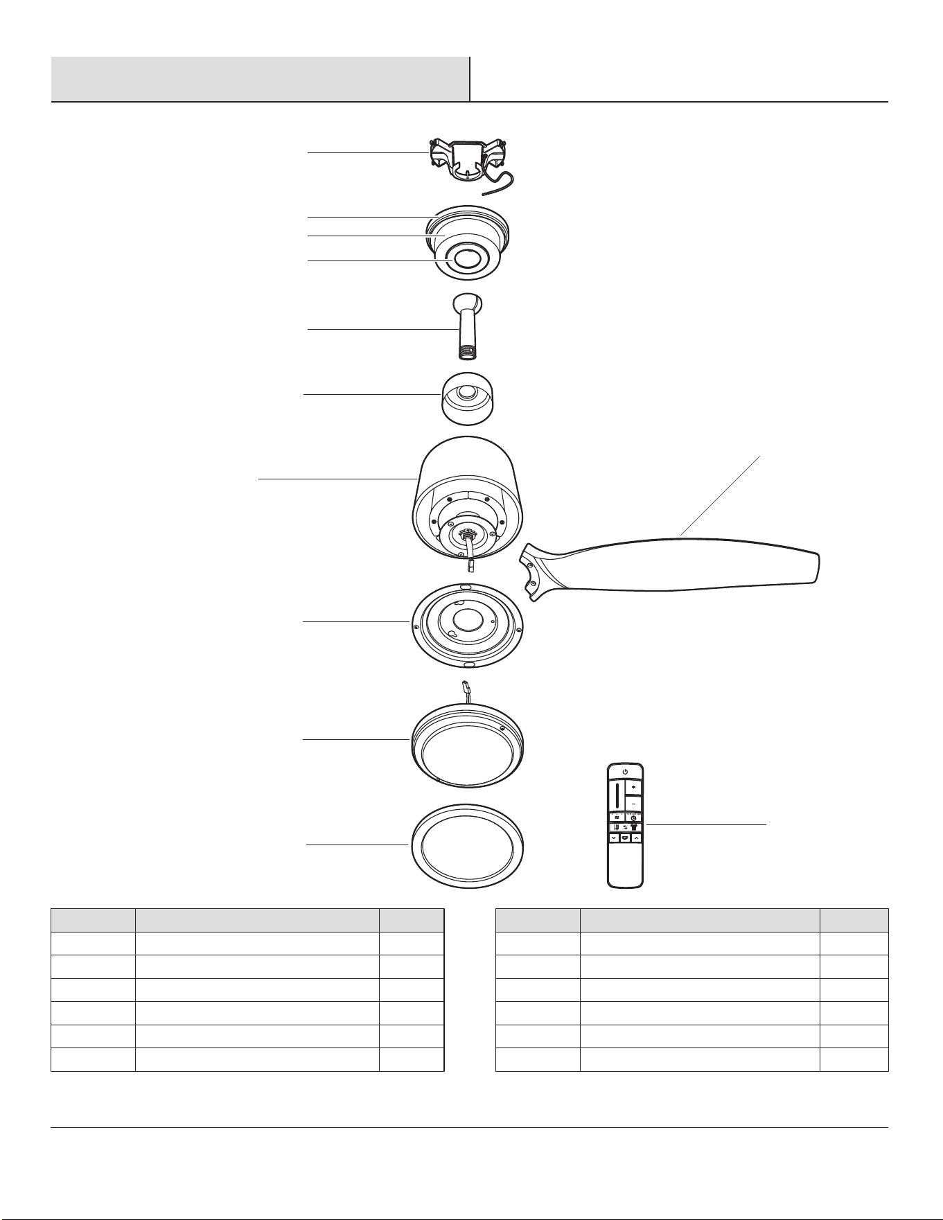
PACKAGE CONTENTS
PACKAGE CONTENTS
Pre-Installation (continued)
6
H
I
J
K
G
L
A
E
F
B
C
D
Part
Part
G
H
I
J
K
L
Description
Description
Fan motor assembly
Blade
Light kit mounting plate
14 watt LED Light kit
Plastic shade
Remote control
Quantity
Quantity
1
3
1
1
1
1
Part
Part
A
B
C
D
E
F
Quantity
Quantity
1
1
1
1
1
1
Description
Description
Mounting bracket (preassembled)
Canopy ring (preassembled)
Canopy
Canopy bottom cover (preassembled)
Hanger ball/downrod assembly
Coupling cover
Pre-Installation (continued)
DUAL MOUNTING INSTRUCTIONS
DUAL MOUNTING INSTRUCTIONS
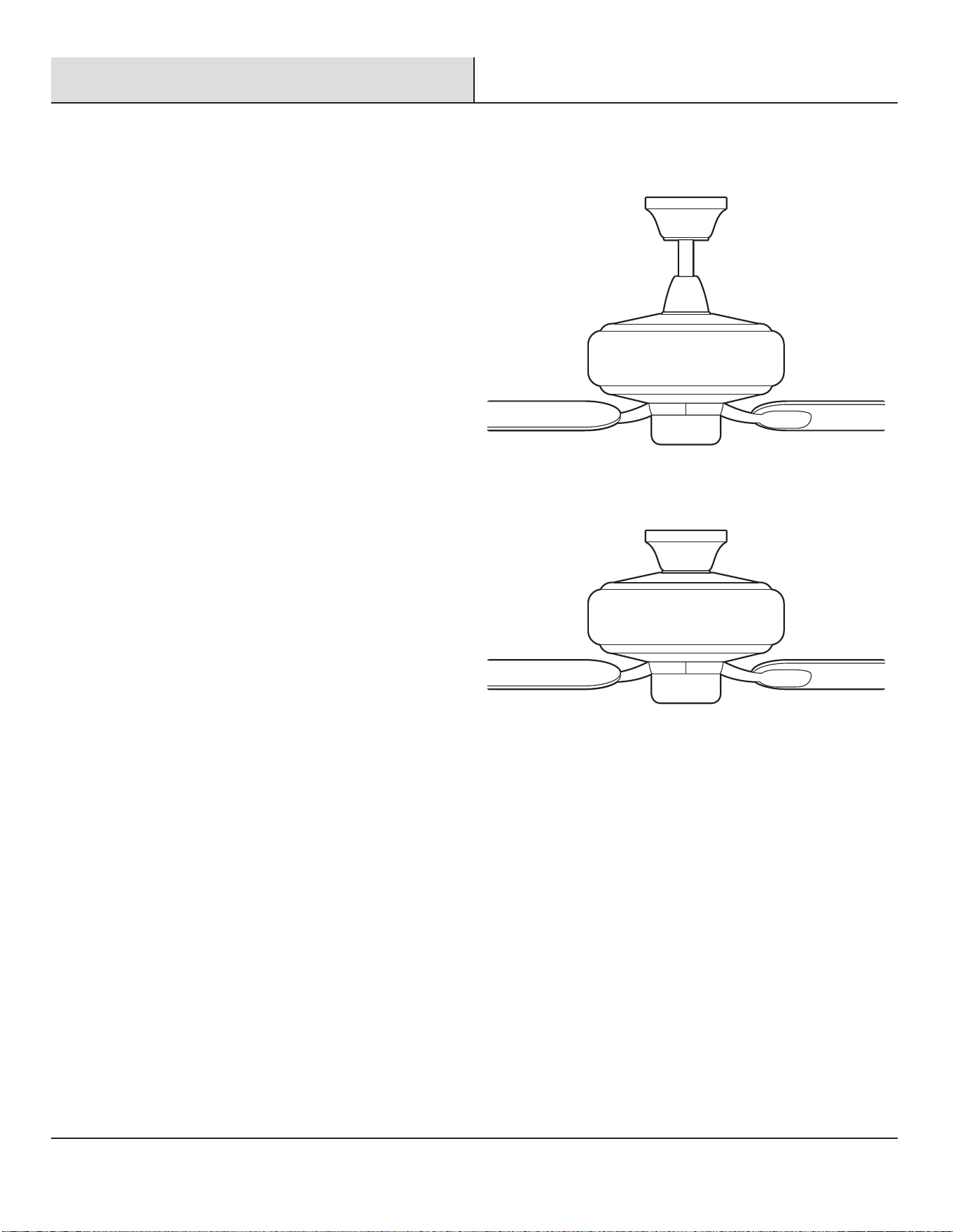
This ceiling fan is supplied with two types of hanging assemblies: the
standard ceiling installation using the downrod with ball and socket
mounting, and the "close-to-ceiling" mounting. The "close-to-ceiling"
mounting is recommended in rooms with less than 8 ft. ceilings or in
areas where additional space is desired from the oor to the fan blades.
When using the standard downrod installation, the distance from the
ceiling to the bottom of the fan blades will be approximately 12 in. The
"close-to-ceiling" installation reduces the distance from the ceiling to the
bottom of the fan blades to approximately 9 in.
Once you have decided which ceiling installation you will use, refer to the
corresponding sections and procedures during the assembly period.
Where necessary, each section of the instructions will note the different
procedures to follow for the two types of installation.
Standard Ceiling Mounting
Close-to-Ceiling Mounting
7 HOMEDEPOT.COM/HOMEDECORATORS
Please contact 1-800-986-3460 for further assistance.
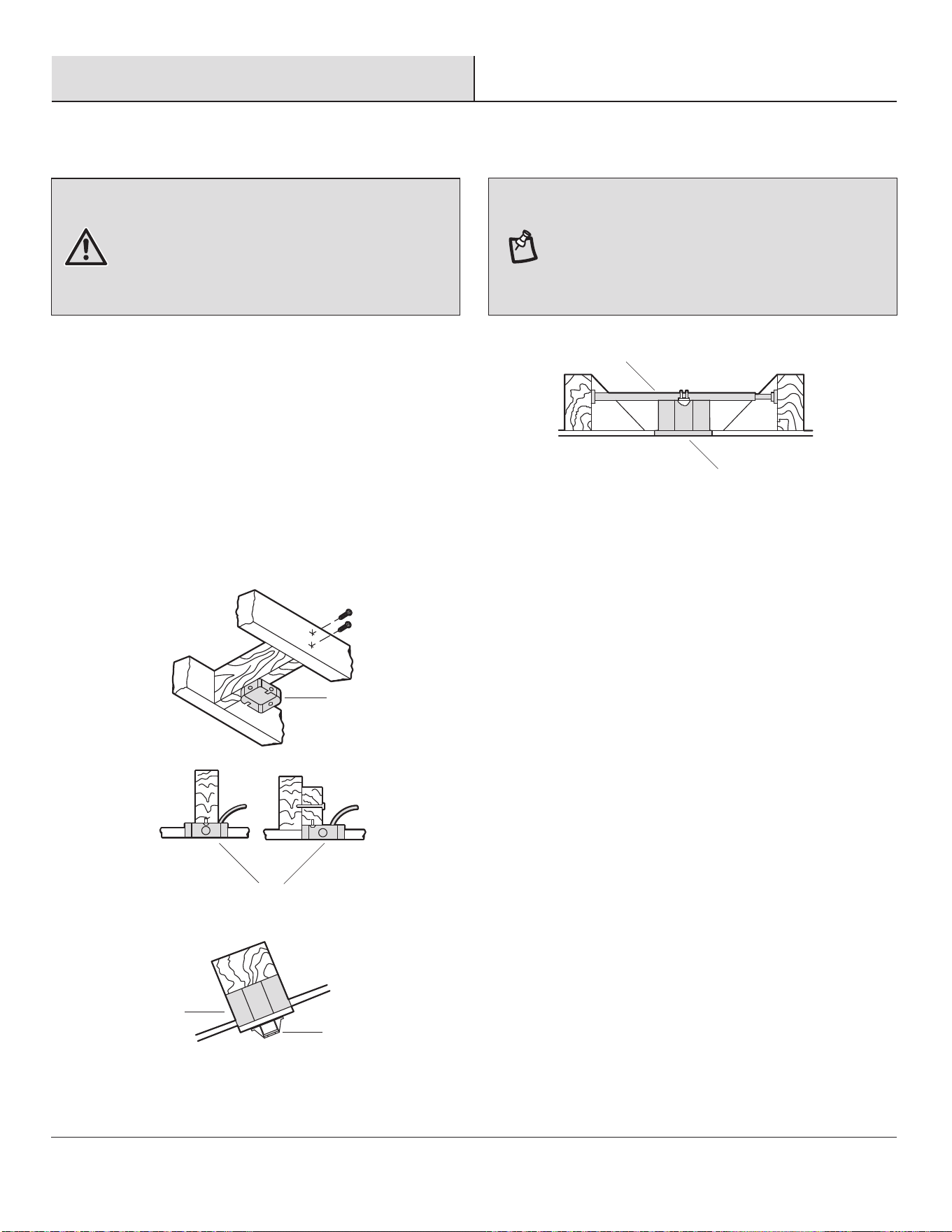
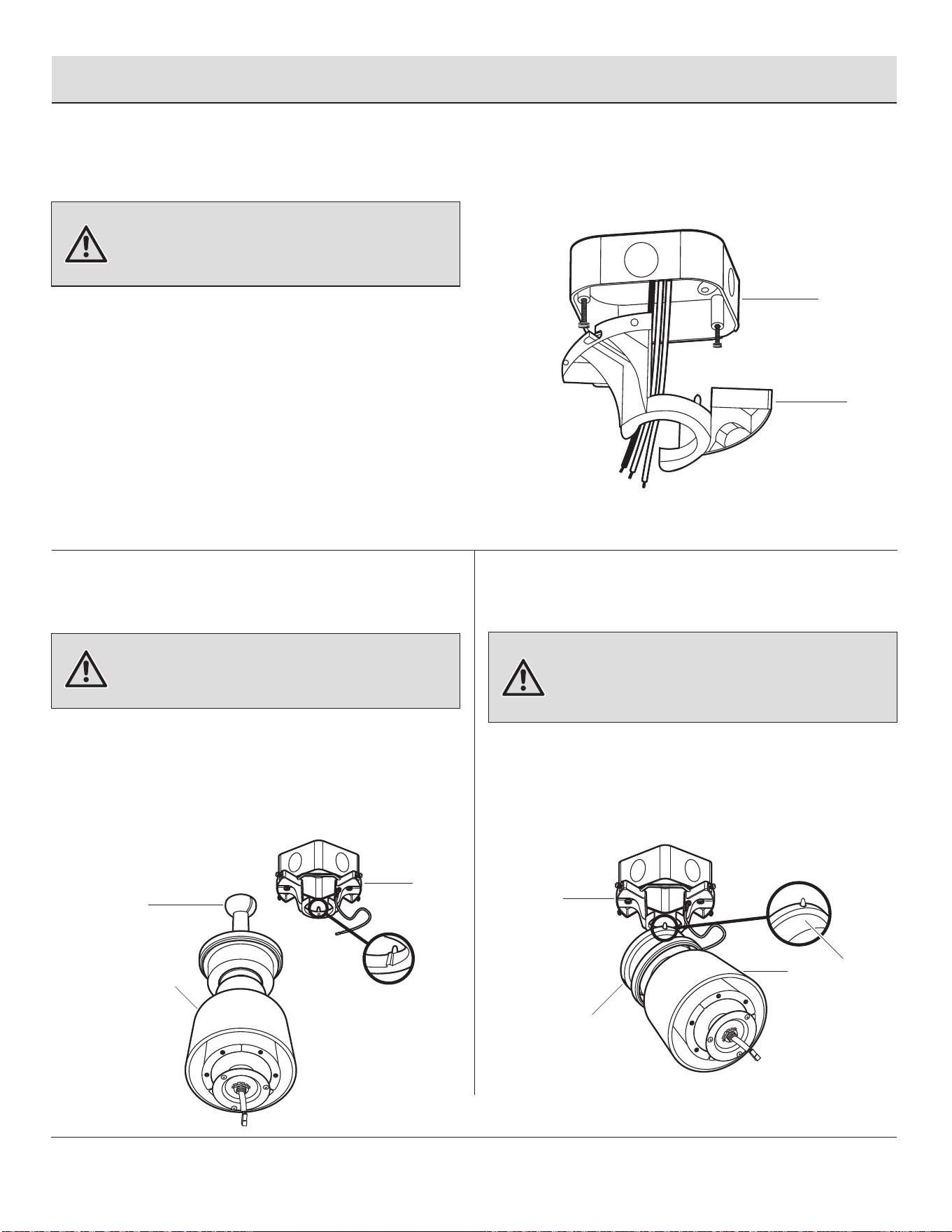
To hang your fan where there is an existing xture but no ceiling
joist, you may need an installation hanger bar (NN) (not included)
as shown above.
If your ceiling fan does not have an existing UL-listed mounting
box, then install one using the following instructions:
□ Disconnect the power by removing the fuses or turning off
the circuit breakers.
□ Secure the outlet box (MM) (not included) directly to the
building structure. Use appropriate fasteners and materials
(not included). The outlet box and its bracing must be able
to fully support the weight of the moving fan (at least 35
lbs.). Do not use a plastic outlet box.
The illustrations below show three different ways to mount the
outlet box (MM) (not included).
MM
MM
NN
MM
MM
A
Installation
MOUNTING OPTIONS
MOUNTING OPTIONS
WARNING: To reduce the risk of re, electric shock, or
personal injury, mount the fan to an outlet box marked
acceptable for fan support using the screws provided with the
outlet box. An outlet box commonly used for the support of
lighting xtures may not be acceptable for fan support and
may need to be replaced. If in doubt, consult a qualied
electrician.
NOTE: You may need a longer downrod to maintain proper
blade clearance when installing on a steep, sloped ceiling.
The maximum angle allowable is 18° away from horizontal. If
the canopy (C) touches the hanger ball/downrod assembly (E),
then remove the decorative canopy bottom cover (D) and turn
the canopy (C) 180° before attaching the canopy (C) to the
mounting bracket (A).
8
1
Preparing the canopy
2
Preparing the motor
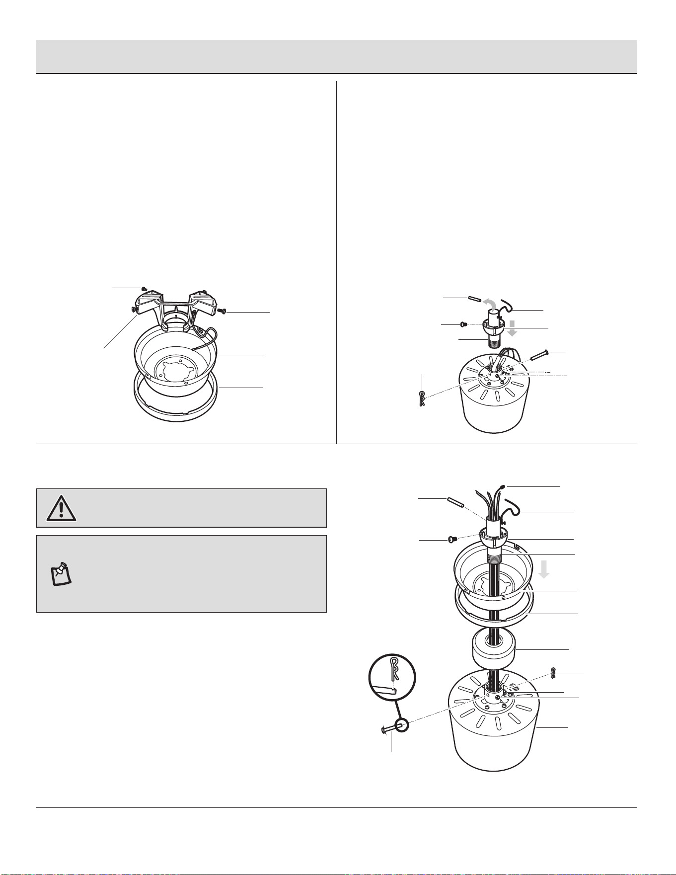
□ Remove the canopy ring (B) from the canopy (C).
□ Remove the two non-slotted canopy mounting screws
(BB) from the canopy (C), and loosen the slotted
canopy mounting screws (BB) on the canopy (C).
□ Remove the canopy (C) from the mounting bracket (A)
by turning the canopy (C) counterclockwise.
3
Assembling the fan
□ Remove the cotter pin (EE) and clevis pin (DD), and
loosen the two collar setscrews (HH) from the motor
collar.
□ Take out the setscrew (GG) located in the hanger ball
(OO), lower the hanger ball (OO) and remove the
cross pin (FF). Remove the hanger ball (OO) from the
hanger ball/downrod assembly (E).
□ Remove the ground lead (PP) from the downrod
assembly (E).
Assembly — Standard Ceiling Mounting
WARNING: Failure to properly install the cotter pin (EE)
could result in the fan loosening and possibly falling.
B
G
F
OO
C
PP
RR
QQ
HH
HH
DD
EE
FF
□ Carefully feed the motor wires and antenna wire (RR)
up through the downrod (QQ). Thread the downrod
(QQ) into the collar.
□ Align the holes and replace the clevis pin (DD) and
cotter pin (EE). Tighten the two collar setscrews (HH).
□ Slip the coupling cover (F), canopy ring (B), and
canopy (C) onto the downrod (QQ).
□ Carefully reinstall the hanger ball (OO) onto the
downrod (QQ) and reinstall the ground lead (PP) onto
the downrod (QQ), being sure that the cross pin (FF)
is in the correct position, the setscrew (GG) is
tightened and wires are not twisted.
NOTE: If a longer downrod (not included) is needed, take out
the screw located in the hanger ball (OO), lower the hanger
ball (OO) and remove the pin (FF). Remove all three pieces
from the downrod and assemble them onto the new longer
downrod before proceeding to the downrod installation.
9
HOMEDEPOT.COM/HOMEDECORATORS
Please contact 1-800-986-3460 for further assistance.
GG
EE
DD
HH
HH
A
BB
BB
C
B
GG
E
FF
OO
PP
10
Assembly — Close-to-Ceiling Mounting
12
3
Assembling the fan
Preparing the motorPreparing the canopy
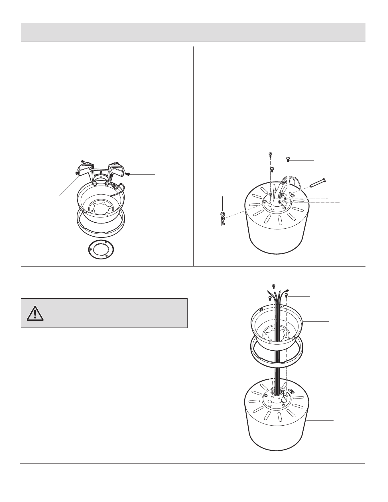
□ Remove the cotter pin (EE), clevis pin (DD) and two
collar setscrews (HH) from the motor collar.
□ Remove three of the six collar mounting screws with
lock washers (II) (every other one) from the collar on
top of the fan motor assembly (G).
WARNING: Failure to completely tighten the three collar
mounting screws (II) could result in the fan becoming loose
and possibly falling.
II
G
□ Remove the canopy ring (B) from the canopy (C).
□ Remove the mounting bracket (A) from the canopy (C)
by loosening the four canopy mounting screws (BB)
on the top of the canopy (C). Remove the two
non-slotted canopy mounting screws (BB) and loosen
the slotted canopy mounting screws (BB).
□ Remove the canopy bottom cover (D) from the
canopy (C).
□ Make sure the slot openings of the canopy ring (B)
are on top, and then proceed to place the canopy ring
(B) and canopy (C) over the collar at the top of the fan
motor assembly (G).
□ Align the mounting holes in the bottom of the canopy
(C) with the holes in the top of the fan motor
assembly (G). Fasten using the three collar mounting
screws with lock washers (II) previously removed.
□ Tighten the collar mounting screws with lock
washers (II) securely.
D
A
BB
BB
C
B
C
B
G
II
EE
DD
HH
HH
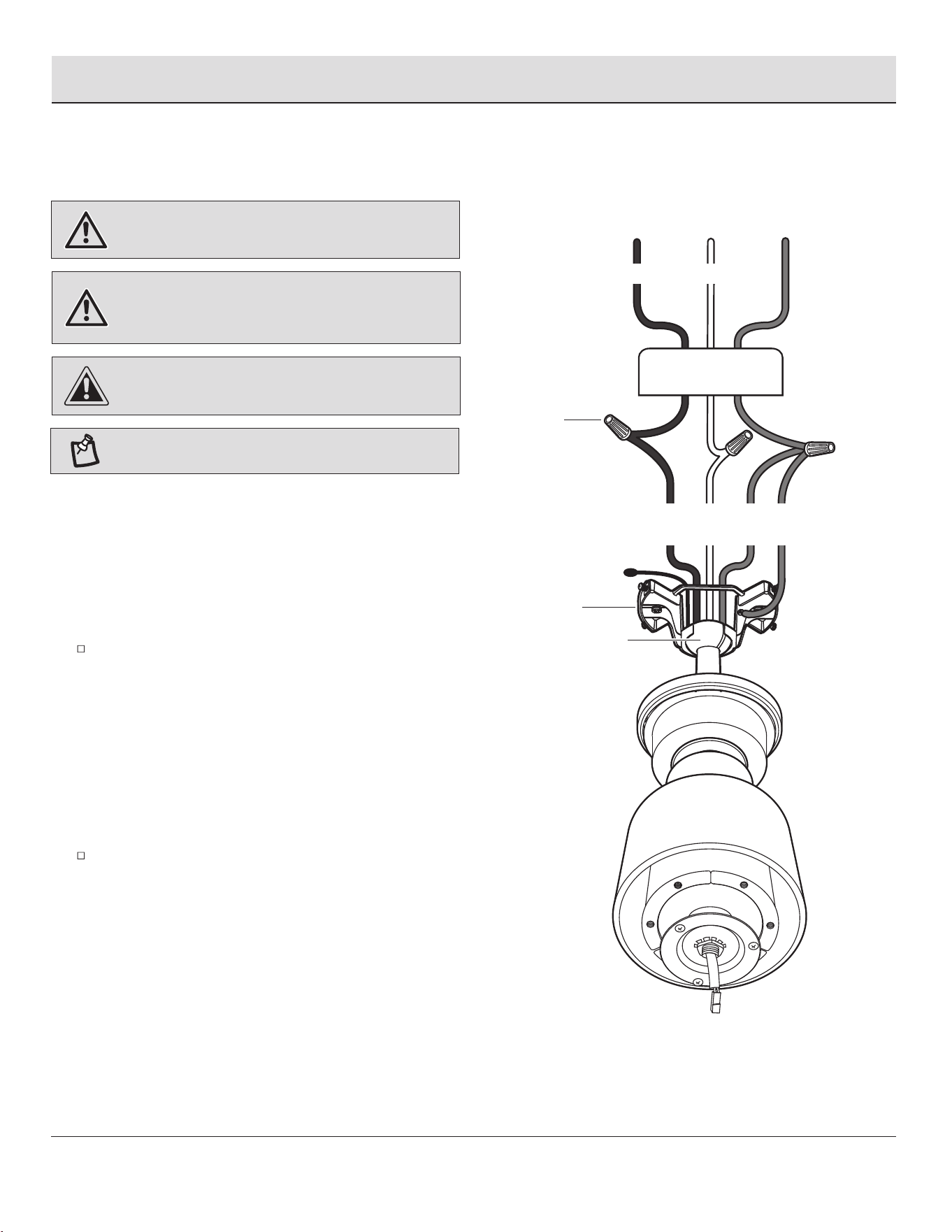
Assembly — Hanging the Fan
4
Attaching the fan to the
electrical box
5b5a
Hanging instructions for
standard mounting
Hanging instructions for
close-to-ceiling mounting
□ Pass the 120-volt supply wires through the center
hole in the mounting bracket (A).
□ Attach the mounting bracket (A) on the outlet box
(MM) by sliding the mounting bracket (A) over the
screws provided with the outlet box. When using
“close-to-ceiling” mounting, it is important that the
mounting bracket (A) be level. If necessary, use
leveling washers (not included) between the
mounting bracket (A) and the outlet box (MM). Note
that the at side of the mounting bracket (A) is
toward the outlet box (MM).
□ Securely tighten the two mounting screws.
WARNING: To reduce the risk of re, electric shock or
other personal injury, mount the fan only to an outlet box or
supporting system marked acceptable for fan support and
use the mounting screws provided with the outlet box.
WARNING: The tab in the ring must rest in the groove of
the hanger ball (E). Failure to properly seat the tab in the
groove could cause damage to the wiring.
WARNING: The hook is only to hold the fan while attaching
wiring. Failure to hang as instructed may result in the tab
breaking causing the fan to fall. The hook must pass from the
inside to the outside of the canopy.
□ Carefully lift the fan motor assembly (G) up to the
mounting bracket (A) and seat the hanger ball (E) in
the mounting bracket (A) socket. Make sure the tab
on the mounting bracket (A) socket is properly seated
in the groove in the hanger ball (E). This will help to
balance the ceiling fan.
□ Carefully lift the fan motor assembly (G) up to the
mounting bracket (A) and hang the fan on the hook
provided using one of the holes at the outer rim of the
canopy (C).
A
E
11
G
HOMEDEPOT.COM/HOMEDECORATORS
Please contact 1-800-986-3460 for further assistance.
A
G
C
C
A
MM
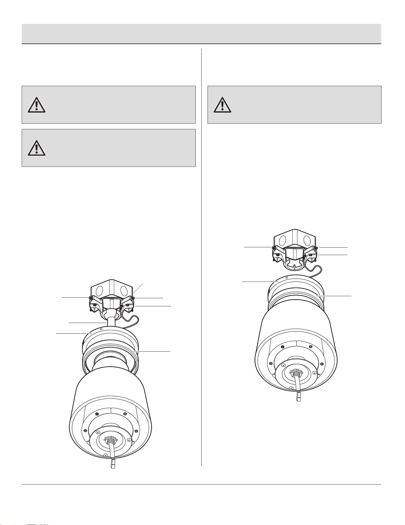
12
Making the electrical connections
Assembly — Hanging the Fan (continued)
6
WARNING: Check to see that all connections are tight,
including ground, and that no bare wire is visible at the wire
nuts (except for the ground wire).
WARNING: To avoid possible electrical shock, be sure
electricity is turned off at the main fuse box before wiring.
CAUTION: To reduce the risk of electric shock, this fan
must be installed with an isolating wall control/switch.
NOTE: DO NOT cut the yellow antenna wire.
Antenna
AA
NeutralHot
Black
Ground
conductor
White
Black
Green
White
Green
MM
A
E
If you feel you do not have enough electrical wiring knowledge
or experience, have your fan installed by a licensed electrician.
Follow the steps below to connect the fan to your household
wiring. Use the plastic wire nuts (AA) with your fan. Secure the
plastic wire nuts (AA) with electrical tape. Make sure there are
no loose strands or connections.
Make wire connections as follows, using the wire nuts (AA).
From Fan To Outlet Box
Black Wire ------------------- Black Wire (Hot)
White Wire ------------------- White Wire (Neutral)
Green Wires* ---------------- Green or Bare Wire (Ground)
* There are two green grounding leads: one from the mounting
bracket (A) and one from the hanger ball/downrod assembly (E) if
installed.
Turn the wire nut connections upward, spreading them
apart so the green (ground) and white wires will be on one
side of the outlet box (MM) and the black wire will be on the
other side. Carefully tuck the connections up into the outlet
box (MM).
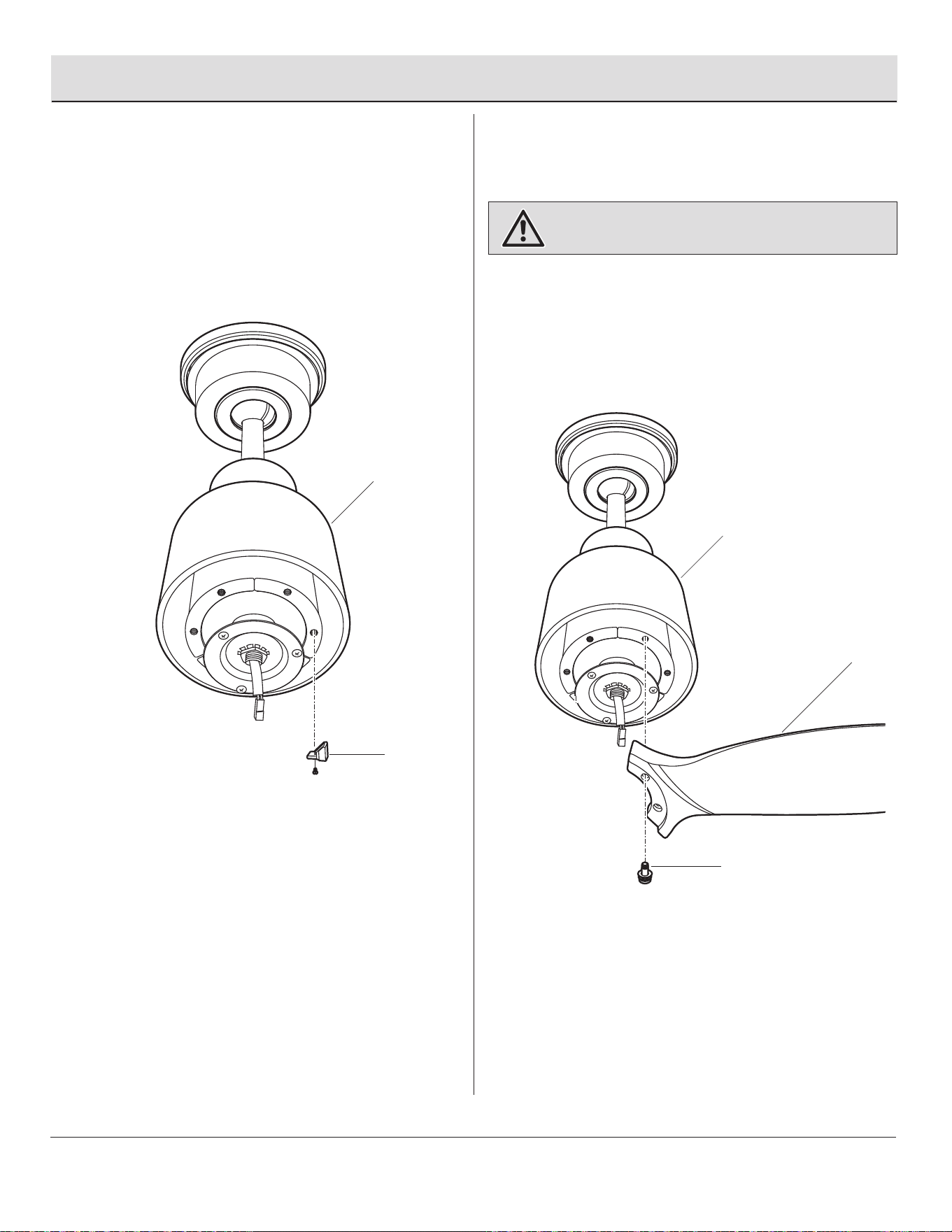
Assembly — Hanging the Fan (continued)
7a
Standard ceiling mounting
7b
Close-to-ceiling mounting
WARNING: The locking slots of the canopy (C) are provided
only as an aid to mounting. Do not leave the fan assembly
unattended until all four canopy mounting screws (BB) are
engaged and rmly tightened.
WARNING: Make sure the tab on the mounting bracket (A)
properly sits in the groove in the hanger ball (E) before
attaching the canopy (C) to the mounting bracket (A) by
turning the canopy (C) until it drops into place.
WARNING: Locking slots of the canopy (C) are provided
only as an aid to mounting. Do not leave the fan assembly
unattended until all four canopy mounting screws (BB) are
engaged and rmly tightened.
□ Slide the canopy (C) up to the ceiling. Make sure you
have placed the wires safely into the outlet box
(MM).
□ Secure the canopy (C) to the mounting bracket (A)
with the four canopy mounting screws with lock
washers (BB) included with your fan.
□ Raise up canopy ring (B) and line up the four grooves
with the four screw heads on the canopy (C). Once
lined up, slide the canopy ring (B) and secure it to the
canopy (C) until snug.
□ Remove the fan from the hook on the mounting
bracket (A).
□ Secure the canopy (C) to the mounting bracket (A)
with the four canopy mounting screws with lock
washers (BB) provided.
□ Raise up canopy ring (B) and line up the four grooves
with the four screw heads on the canopy (C). Once
lined up, slide the canopy ring (B) and secure it to the
canopy (C) until snug.
13
HOMEDEPOT.COM/HOMEDECORATORS
Please contact 1-800-986-3460 for further assistance.
BB
MM
A
BB
E
BB
A
BB
B
C
B
C
9
Fastening the blade
assemblies to the motor
WARNING: To reduce the risk of personal injury, do not
insert foreign objects between rotating fan blades (H).
□ Align the holes from the blade (H) to the holes from
the motor (G), and secure the blade in place with
screws and washers (CC) provided.
□ Repeat this process to attach the other two blades
(H).
Assembly — Attaching the Fan Blades
14
G
CC
H
8
Removing the rubber
packing mounts
□ The fan motor assembly (G) is shipped with rubber
packing mounts (SS) to prevent movement during
transportation. Remove the six rubber packing
mounts (SS) from the fan motor assembly (G) and
discard prior to attaching the blades.
G
SS
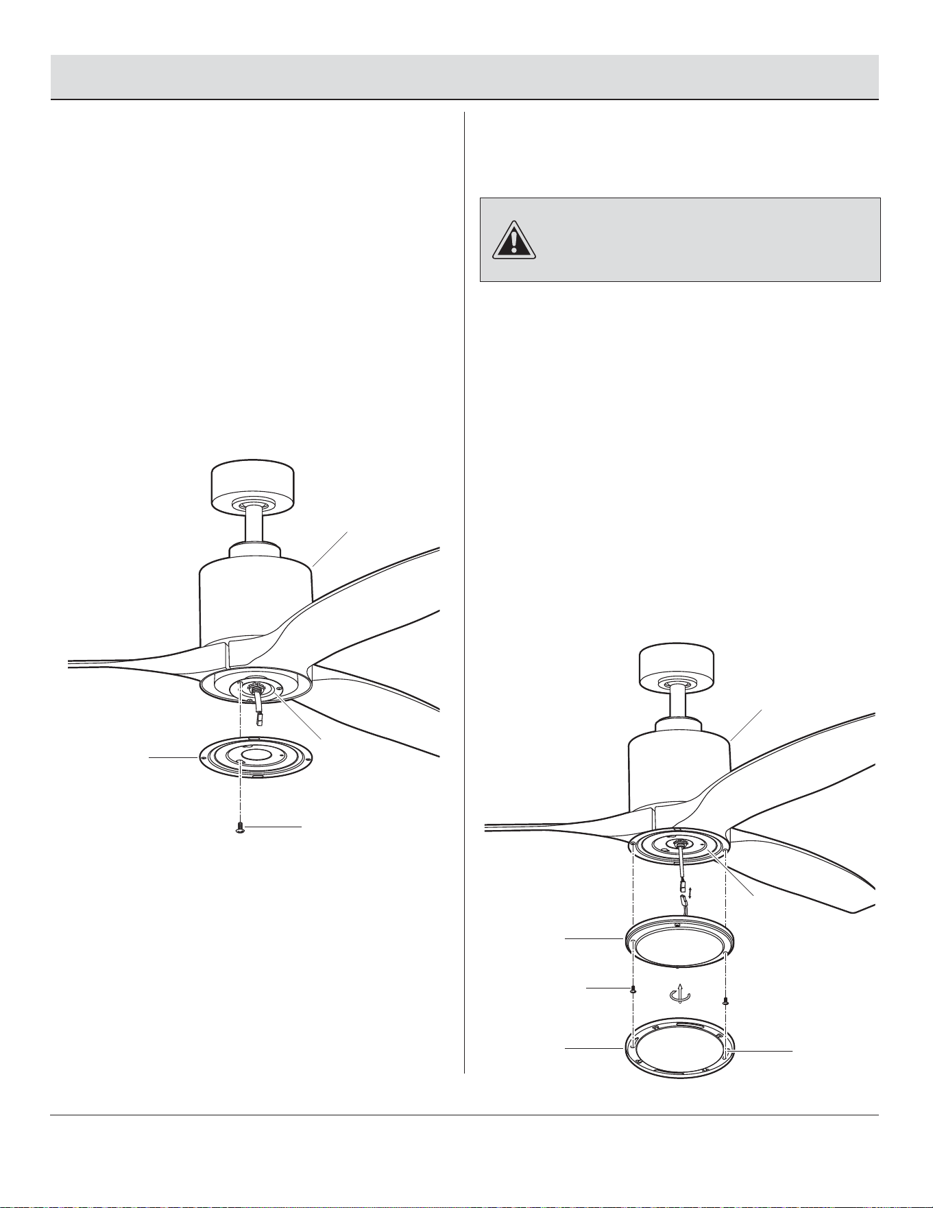
10
Attaching the light kit mounting
plate to the mounting ring
Assembly — Installing the Light Kit
□ Remove one of the three light kit mounting plate
screws (JJ) from the mounting ring (TT) and loosen
the other two screws. (Do not remove.)
□ Place the key holes in the light kit mounting plate (I)
over the two screws (JJ) previously loosened from
the mounting ring (TT). Turn the light kit mounting
plate (I) until the light kit mounting plate (I) locks in
place at the narrow section of the key holes.
□ Securely tighten the two light kit mounting plate
screws (JJ) previously loosened and the one (JJ)
previously removed.
15
HOMEDEPOT.COM/HOMEDECORATORS
Please contact 1-800-986-3460 for further assistance.
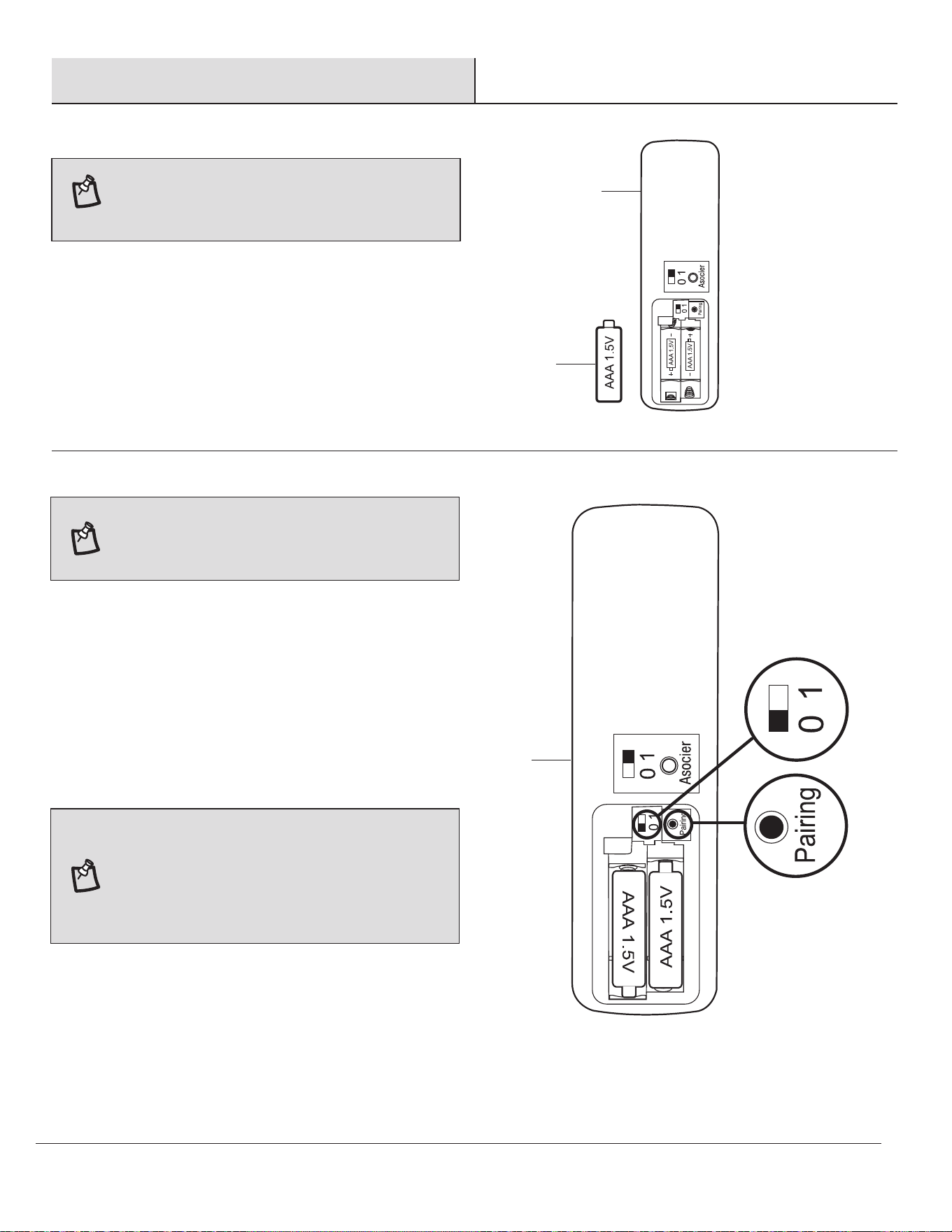
11
Attaching the LED light kit
and plastic shade
CAUTION: Before starting installation, disconnect the
power by turning off the circuit breaker or removing the fuse
at the fuse box. Turning power off using the fan switch is not
sufcient to prevent electric shock.
□ Remove the two light kit mounting screws (KK) from
the light kit mounting plate (I).
□ While holding the 14W LED light kit (J) under the fan
motor assembly (G), make the 2-pin wire connections:
- White to white
- Black to black
□ Carefully tuck all wire connections back into the 14W
LED light kit (J), then install the 14W LED light kit (J)
onto the light kit mounting plate (I) with two light kit
mounting screws (KK) previously removed. Be sure to
tighten all screws.
□ Attach the plastic shade (K) to the 14W LED light kit
(J) by inserting the two light kit mounting screws (KK)
into the key slots (UU) in the plastic shade (K) and
rotating the plastic shade (K) clockwise.
TT
G
I
JJ
G
KK
K
J
UU
I
16
Operation
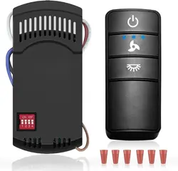
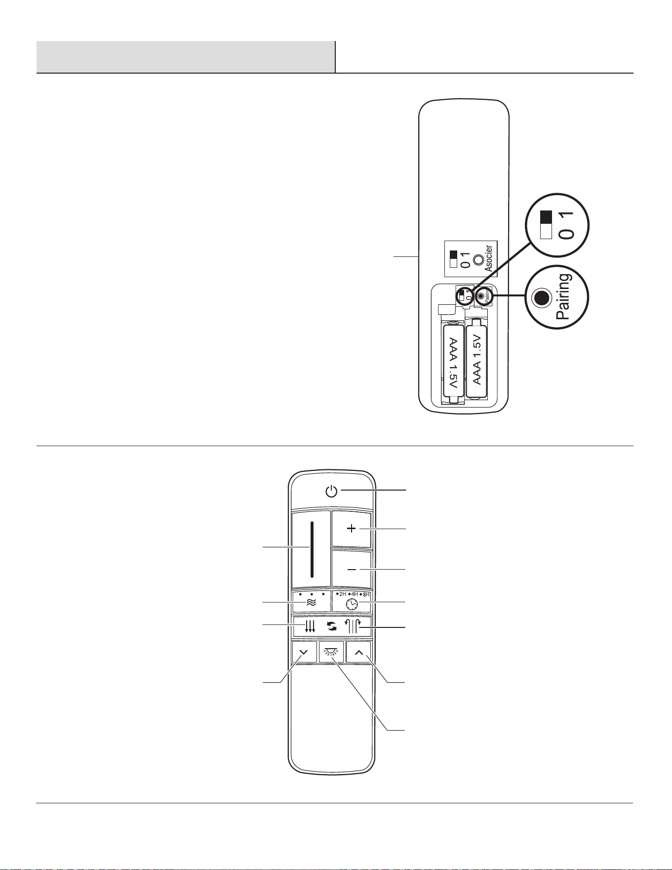
□ Remove the battery cover by pressing rmly on the arrow and
sliding the cover off.
□ Install two 1.5V AAA batteries (LL) (included).
□ Replace the battery cover on the remote control (L).
PREPARING THE TRANSMITTER
NOTE: Batteries will weaken with age and should be
replaced before leaking takes place as this will damage
the remote control. Dispose of used batteries properly
and keep them out of the reach of children.
The learning process causes any installed fan within range to
memorize a remote control. Fans can learn ve remotes.
To add a remote to your fan’s memory, use the steps below:
□ Ensure AC power to the fan is OFF to begin the learning
process.
□ Slide the dip switch in the battery compartment to the "1"
position.
□ Turn the fan’s AC power ON.
□ Within 60 seconds of turning AC power on, press and release the
" Pairing" button located in the remote's battery compartment
to enter the learning function. Once the fan has detected the
remote controls's frequency, the down light of your fan, if
applicable, will blink, and the fan blades will start to spin.
□ The fan will now accept commands from the added remote.
LEARNING PROCESS
NOTE: If installing multiple fans on separate remotes,
only the fan being programmed should have AC power
turned ON. All other fans, even if they have already
been programmed, should have AC power OFF so they
do not memorize other remotes during the learning
process. Separate the fan power switches by
approximately 2 meters.
NOTE: The dip switch in the battery compartment has
been set on “0” position and paired for your
convenience. If you have two or more fans, please
follow steps below to control each fan independently.
LL
L
L
17
HOMEDEPOT.COM/HOMEDECORATORS
Please contact 1-800-986-3460 for further assistance.
Operation (continued)
To clear all other remotes from your fan’s memory, use the steps
below:
□ Ensure AC power to the fan is OFF to begin the learning
process.
□ Slide the dip switch in the battery compartment to the "0"
position.
□ Turn the fan’s AC power ON.
□ Within 60 seconds of turning AC power ON, press and release
the “Pairing” button located in the remote’s battery
compartment, and your fan will restore to the original setting
and dismiss the other remotes.
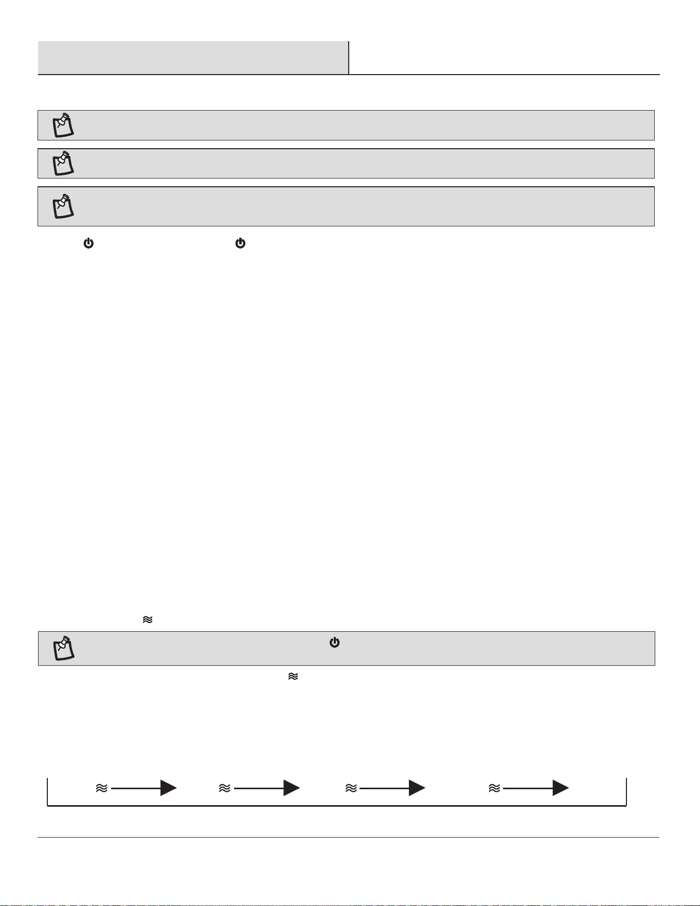
Timer
Fan on/off
Light on/off
Decreases the
light level
(Dimmer)
Warm weather
(Forward)
Comfort Breeze
TM
LED bar
Scale indicating
fan speed
Cool weather
(Reverse)
Increases the
light level
(Dimmer)
Decreases fan speed
Increases fan speed
L
18
Operation (continued)
1. Fan button. - Press and release the button to turn the fan on or off.
□ When turned on, the fan will begin spinning using its last speed settings. The remote control’s LED bar will display the speed setting
for 5 seconds.
□ When turned off, the fan will stop spinning and the light from the remote control’s LED bar will quickly darken from top to bottom.
Off Setting 1 Setting 2 Setting 3 Disable Comfort Breeze
TM
OPERATING YOUR FAN AND REMOTE CONTROL
2. Speed functions
+ button, increases the fan speed
□ Pressing and releasing the + button one time will increase the speed of the fan. Each setting increase will cause the LED bar to
illuminate slightly more, until the fan has reached the maximum speed setting, at that time the LED bar will be fully illuminated.
□ Pressing and holding the + button will increase the fan speed automatically through the speed settings and the increments will be
denoted on the LED bar. When the LED bar is fully illuminated, the fan has reached maximum speed setting.
□ Pressing the + button while in Comfort Breeze
TM
mode will automatically cancel the Comfort Breeze
TM
mode and resume normal fan
operation.
– button, decreases fan speed
□ Pressing and releasing the - button one time will decrease the speed of the fan. Each setting decrease will cause the LED bar to dim
slightly more, until the fan has reached the minimum speed setting. At that time the LED bar will be approximately 25% illuminated.
□ Pressing and holding the - button will decrease the fan speed automatically through the speed settings and the reductions will be
denoted on the LED bar. When the LED bar is 25% illuminated, the fan has reached the minimum speed setting.
□ Pressing the - button while in Comfort Breeze
TM
mode will automatically cancel the Comfort Breeze
TM
mode and resume normal fan
operation.
3. Comfort Breeze
TM
There are three Comfort Breeze
TM
settings. Pressing the button will activate the Comfort Breeze
TM
mode and the LED bar will illuminate
slowly from bottom to top to display the current setting.
□ Setting 1: Alternates through speeds 1 – 3, the LED bar should ll approximately 33%.
□ Setting 2: Alternates through speeds 1 – 6, the LED bar should ll approximately 66%.
□ Setting 3: Alternates through speeds 1 – 9, the LED bar should be fully illuminated.
NOTE: The fan will store the last used speed setting for the next time it is turned on.
NOTE: You must turn the fan on prior to using the speed or time functions.
NOTE: On each start up of your ceiling fan, the fan blades will oscillate back and forth. This is a NORMAL OPERATION for DC motor ceiling
fans as they go through a calibration cycle. The fan is NOT DEFECTIVE.
NOTE: If you are using Comfort Breeze
TM
mode, pressing the button or the fan speed buttons will cancel Comfort Breeze
TM
mode and
resume normal fan operation.
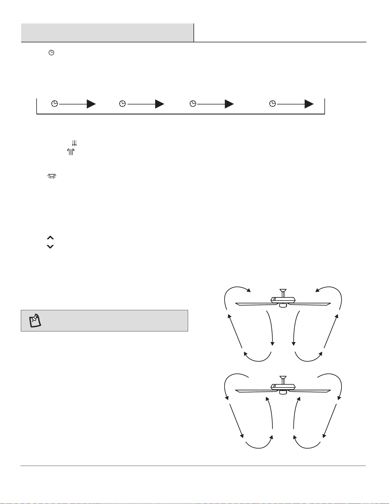
4. Timer
□ Pressing the timer buttons will automatically turn fan and light (if light is on) off after 2, 4, or 8 hours. When you activate the timer
mode, the LED to the left of the time above the clock will illuminate.
19
HOMEDEPOT.COM/HOMEDECORATORS
Please contact 1-800-986-3460 for further assistance.
Operation (continued)
WARM/COOL WEATHER OPERATING INSTRUCTIONS
Speed settings for warm or cool weather depend on factors such
as the room size, ceiling height, numbers of fans.
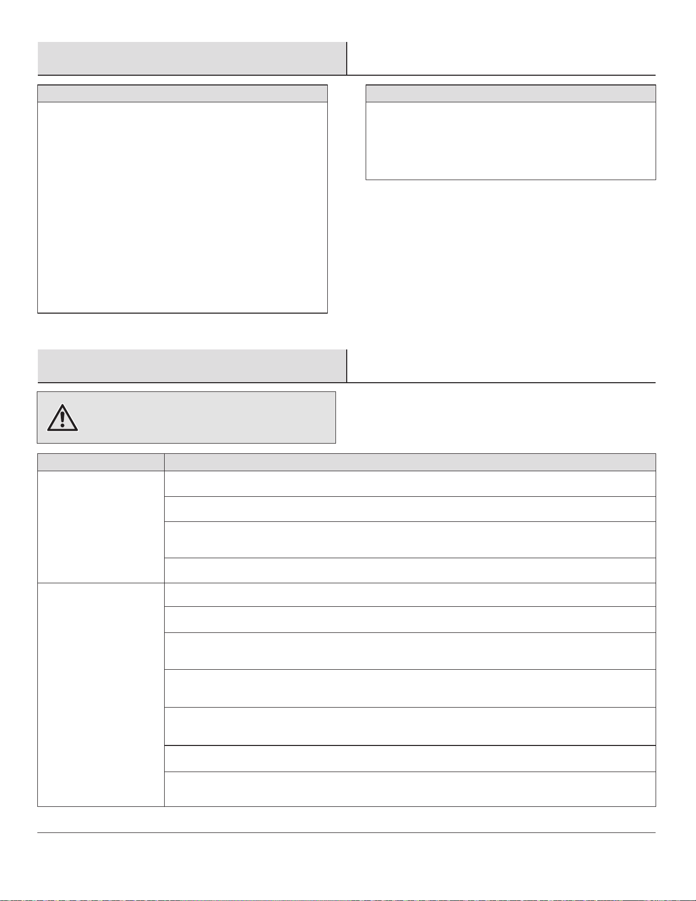
Warm weather - (Counterclockwise Direction) A downward air ow
creates a cooling effect. This allows you to set your air conditioner
on a warmer setting without affecting your comfort.
Cool weather - (Clockwise Direction) An upward air ow moves
warm air off the ceiling. This allows you to set your heating unit on
a cooler setting without affecting your comfort.
NOTE: The fan reverse buttons must be pressed while the
fan is running.
Off 2H 4H 8H Disables timer
6. Light
□ Press and release the light button to turn the light on or off.
□ Light on: The fan memory function will resume the light setting (on or off and dim) on the fan prior to the power being turned off.
7 Dimmer
□ Press to increase the desired light level.
□ Press to decrease the desired light level.
5. Fan reverse button (Must be pushed when the fan is in operation)
□ Warm weather: LED bar will illuminate and the lights will ow from high to low.
□ Cool weather: LED bar will illuminate and the lights will ow from low to high.
20
Care and Cleaning
Troubleshooting
□ Check the support connections, brackets, and blade
attachments twice a year. Make sure they are secure.
Because of the fan’s natural movement, some
connections may become loose over time. It is not
necessary to remove the fan from the ceiling.
□ Clean your fan periodically. Use only a soft brush or
lint-free cloth to avoid scratching the nish. The plating is
sealed with a lacquer to minimize discoloration or
tarnishing.
□ (Optional) Apply a light coat of furniture polish to the wood
blades.
□ (Optional) Cover small scratches with a light application of
shoe polish.
Do
Do
□ Use water when cleaning. Water could damage the motor,
or the wood, or possibly cause an electrical shock.
□ Apply oil to your fan or motor. The motor has
permanently-lubricated sealed ball bearings.
Do not
Do not
WARNING: Make sure the power is off at the electrical
panel box before you attempt any repairs. Refer to the section
“Making the Electrical Connections” on page 12.
Problem
Problem
Solution
Solution
□ Check the main and branch circuit fuses or breakers.
□ Check the line wire connections to the fan and switch wire connections in the switch housing.
□ Check to make sure the frequency switches from the remote control and receiver are set to the same
frequency.
□ Reset the transmitter by going through the transmitter “LEARNING PROCESS”.
□ Make sure all motor housing screws are snug.
□ Make sure the screws that attach the fan blade arm to the motor hub are tight.
□ Make sure the wire nut connections are not rattling against each other or the interior wall of the switch
housing.
□ Allow a 24-hour "breaking-in" period. Most noises associated with a new fan disappear during this
time.
□ If using the ceiling light kit, make sure the screws securing are tight. Check that the light bulb is also
secure.
□ Make sure there is a short distance from the ceiling to the canopy. It should not touch the ceiling.
□ Make sure your ceiling box is secure and that rubber isolator pads are used between the mounting
bracket and outlet box.
The fan will not start.
The fan sounds noisy.
21
HOMEDEPOT.COM/HOMEDECORATORS
Please contact 1-800-986-3460 for further assistance.
Troubleshooting (continued)
Problem
Problem
Solution
Solution
□ Do not connect the fan with wall mounted variable speed control(s).
□ Make sure the frequency switches are set correctly.
□ Reset the transmitter by going through the transmitter “LEARNING PROCESS”.
□ This is normal start-up procedure for DC motor fans. The partial movement during start-up is the result
of the DC motor aligning the internal magnetic poles for proper motor operation. This design saves
electricity and allows the fan to operate much quieter than standard AC motor fans.
The fan wobbles.
The remote control is
not working.
Fan moves backwards and
forwards when turned on.
□
Verify that all blades and blade bracket screws are secure (most fan wobble problems are caused by
loose parts). Once the fan is properly installed, run the ceiling fan for 10 minutes to let the fan
self-adjust.
If wobble occurs after running the fan for 10 minutes, verify blade level using the following process:
- Select a point on the ceiling above the tip of one of the blades, then select any fan blade and
measure from the center of the selected blade to the point on the ceiling. Rotate the fan until the next
blade is positioned and repeat the measurement using the same point from the ceiling for every blade.
Measurement deviations should be within 1/8 in..
- If all deviations are less than 1/8 in. and the fan continues to wobble, please call Customer Service
(1-800-986-3460) to order a complimentary Blade Balancing Kit.
- If deviation is greater than 1/8 in. , please call Customer Service (1-800-986-3460) to order
complimentary replacements of your brackets.
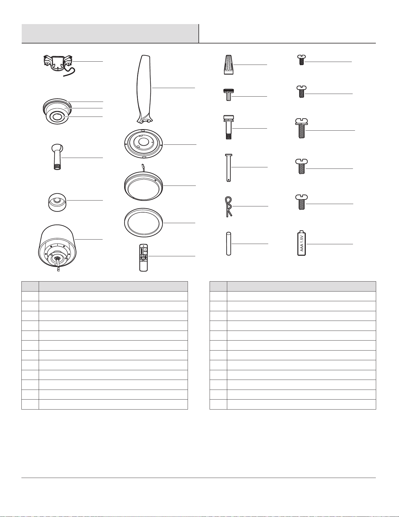
Part
Part
A
B
C
D
E
F
G
H
I
J
K
L
Description
Description
Mounting bracket (preassembled)
Canopy ring (preassembled)
Canopy
Canopy bottom cover (preassembled)
Hanger ball/downrod assembly
Coupling cover
Fan motor assembly
Blade
Light kit mounting plate
14 watt LED Light kit
Plastic shade
Remote control
Part
Part
AA
BB
CC
DD
EE
FF
GG
HH
II
JJ
KK
LL
Description
Description
Plastic wire nut
Canopy mounting screw with washer (preassembled)
Blade screw with lock washer and metal washer
Clevis pin (preassembled)
Cotter pin (preassembled)
Cross pin (preassembled)
Setscrew (preassembled)
Collar setscrew (preassembled)
Collar mounting screw with lock washer (preassembled)
Light kit mounting plate screw (preassembled)
Light kit mounting screw (preassembled)
1.5V AAA battery
Service Parts
J
H
I
AA
HH
II
KK
JJ
LL
BB
CC
DD
EE
FF
GG
K
L
A
E
F
G
B
C
D
22

Questions, problems, missing parts? Before returning to the store,
call Home Decorators Collection Customer Service
8 a.m. - 7 p.m., EST, Monday-Friday, 9 a.m. - 6 p.m., EST Saturday
1-800-986-3460
HOMEDEPOT.COM/HOMEDECORATORS
Retain this manual for future use.