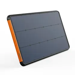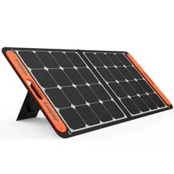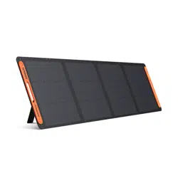
Jackery SolarSaga 100 Prime
Installation Guide
Version: JAK-UM-V1.0
*The following installation method is for reference only. The installers are required to follow all
installation guidelines.
*Make sure that the solar panels are securely mounted to withstand all expected loads, such as
wind loads and snow loads. A minimum gap of at least 0.25 in (6.5 mm) is required between solar
panels to allow for thermal expansion distance of the frame.
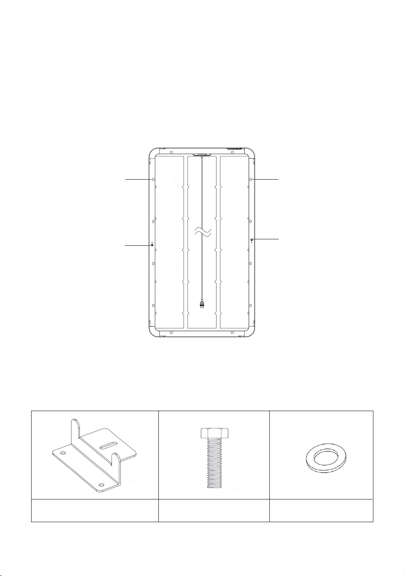
*The solar panels must be mounted using the pre-drilled holes on the frame as mounting holes
(length * width: 14 mm x 9 mm). The most common installation method is using four symmetric
points near the inner side of the frame. Please refer to the following figure:
1.1 WARNING
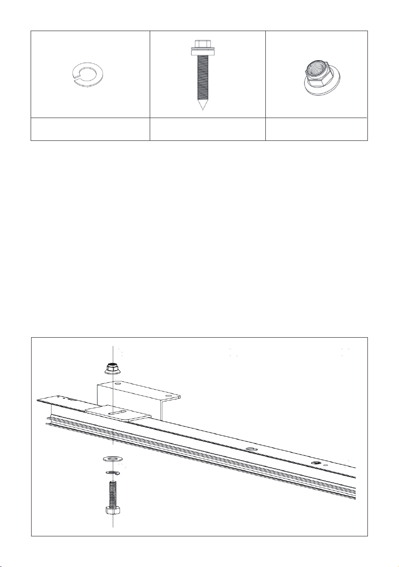
Jackery Z Bracket Kit is required for installation, including: 4 Z-shaped brackets, 4 M6 hex bolts, 4
M6 flat washers, 4 M6 elastic washers, 4 M6 nylon anti-loosening flange nuts, and 8 M5.5 hex
flange self-tapping screws with adhesive.
1.2 INSTALLATION
01
Mounting hole Vent hole
Grounding mark
Grounding hole
Z-shaped brackets × 4 Hex bolts × 4 M6 flat washers × 4
*Use stainless steel as corrosion-resistant fastening material.
*Do not drill holes or modify the frame, as this will void the warranty.
*Each solar panel must be fixed with at least 2 anchor points on each side. The number of
installation bolts used is at the discretion of the professional installer.
*Installation must be done with M6 stainless steel bolts, nuts and washers using the mounting holes
located on the back side of the solar panel.
*When installing on the roof or body of the vehicle, note that there must be a gap between the
solar panel and the vehicle surface to facilitate air circulation and heat dissipation.
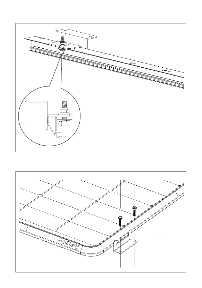
1. Place the Z-shaped bracket in the corresponding position of the pre-drilled hole on the solar
panel, and install the hex bolt (M6), flat washer (M6), and elastic washer (M6).
STEP-BY-STEP INSTALLATION GUIDE
02
M6 elastic washers × 4
M5.5 hex flange self-tapping
screws with adhesive × 8
M6 nylon anti-loosening
flange nuts × 4
03
2. Tighten the nuts.
3. Place the solar panel with the installed Z-shaped bracket in the prepared installation position on
the roof, and drill holes in the corresponding Z-shaped bracket base on the roof.
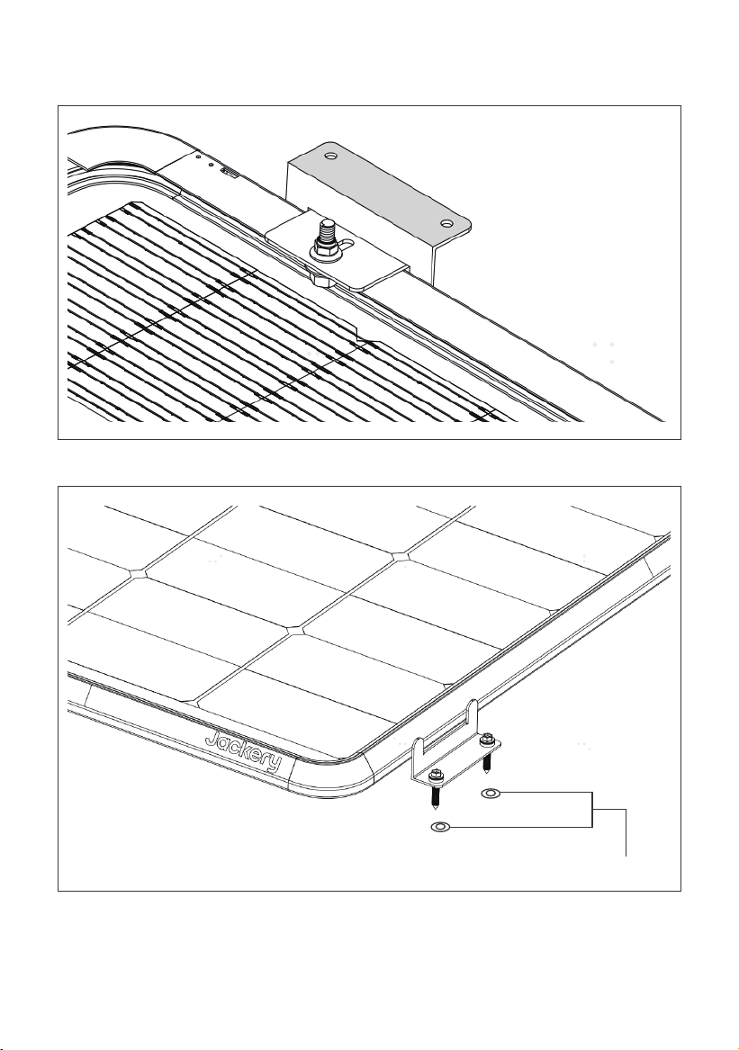
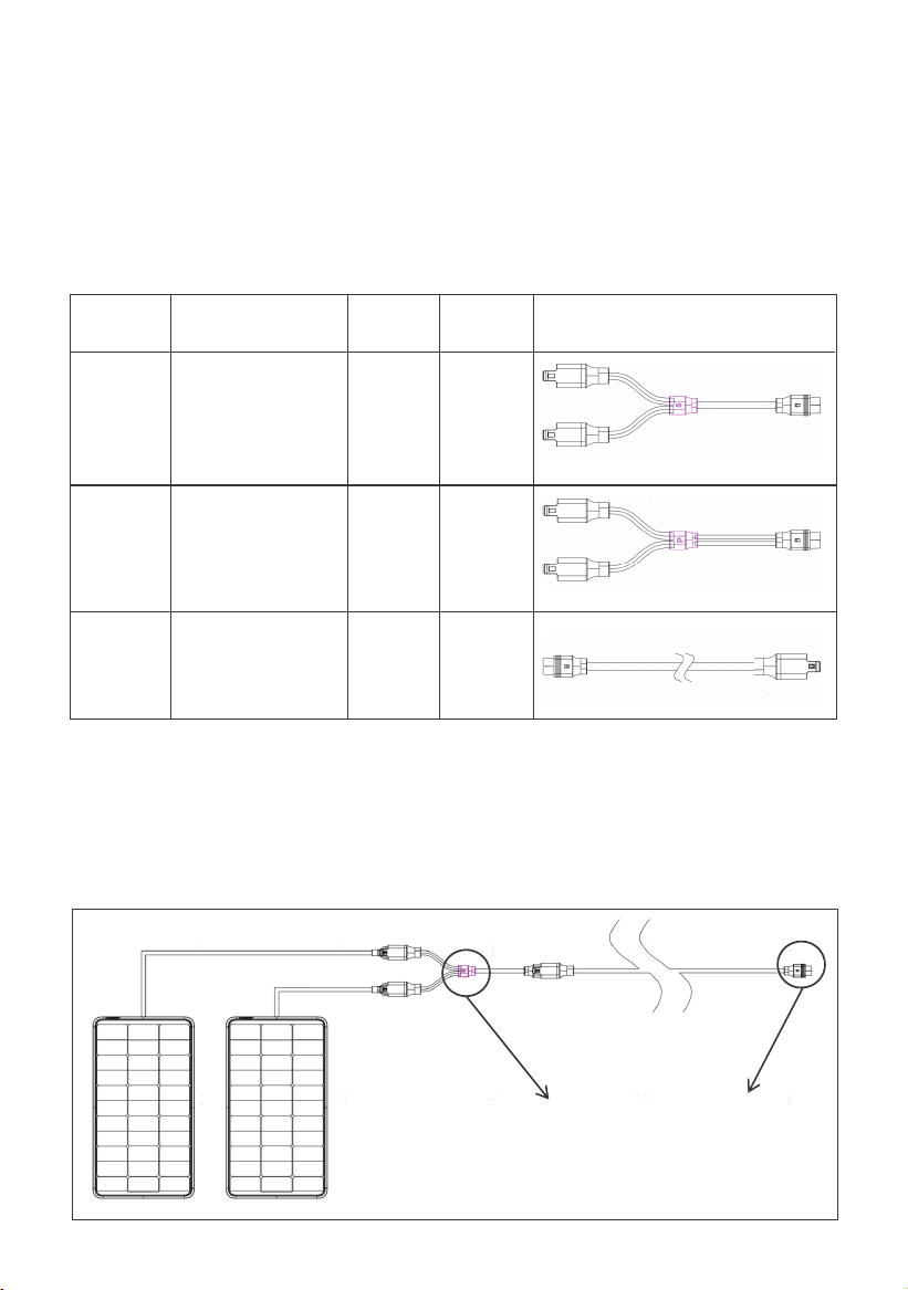
4. Apply structural adhesive evenly to the bottom of the Z-shaped bracket (as shown in the
selected area in the following figure).
5. Clean the holes, and apply structural adhesive evenly around the holes.
6.After aligning the Z-shaped bracket base of the solar panel with the roof hole, install the hex
flange self-tapping screws, leave them stand for 24 hours, and wait for the structural adhesive to
cure (ambient temperature ≤ 30℃, humidity ≤ 70%RH).
7. Once the structural adhesive is cured, clean the residue on the base and roof.
Adhesive application area
04
1.3 TECHNICAL REQUIREMENTS FOR ELECTRICAL CONNECTION
ACCESSORIES DESCRIPTION:
HOW TO CONNECT JACKERY PORTABLE POWER STATION:
When it is necessary to increase the system voltage or current, the Jackery Anderson Y Parallel
Connector and Jackery Anderson Y Series Connector can be used for connection. Make sure to
connect the male head of the solar panel end to the corresponding female head of the
connector, once you hear the "click" sound of the Anderson Connector, the connection is
successful.
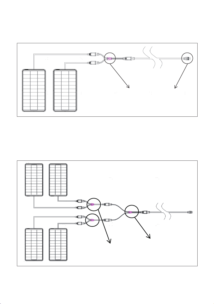
1) Applicable models: Explorer 600 Plus/ Explorer 1000 V2
A single DC input port supports a maximum of 2 SolarSaga 100 Prime panels in series. The Explorer
600 Plus supports up to 2 SolarSaga 100 Prime panels, and the Explorer 1000 V2 supports up to 4
SolarSaga 100 Prime panels. The connection diagram is as follows:
05
Model Product Name
Maximum
Voltage
Maximum
Current
JA-SC01A
Jackery Anderson
Y Series Connector
120V 20A
Illustration
the surface of parallel connector is marked with "P"
the surface of series connector is marked with "S"
JA-PC01A
Jackery Anderson
Y Parallel Connector
120V 25A
JA-CA03A
Jackery Anderson
Extension Cable
120V 20A
JA-SC01A
JA-CA03A
06
2) Applicable model: Explorer 1500
A single DC input port supports a maximum of 2 SolarSaga 100 Prime panels in parallel. The
Explorer 1500 supports up to 4 SolarSaga 100 Prime panels. The connection diagram is as follows:
3) Applicable model: Explorer 1000 Plus
A single DC input port supports a maximum of 4 SolarSaga 100 Prime panels in series and parallel
combination. The Explorer 1000 Plus supports up to 8 SolarSaga 100 Prime panels. The connec-
tion diagram is as follows:
JA-PC01A
JA-CA03A
JA-SC01A
JA-PC01A
Caution:
1. The above component connection diagrams are for reference only. For the connection of
multiple photovoltaic components, it is necessary to match them according to the maximum input
voltage and current of the receiving end. After series and parallel connection, the total output
voltage of the photovoltaic panels should not exceed the maximum voltage value at the
receiving end, and the total output current should not exceed the maximum current value.
2. Due to the limitations of Jackery Anderson Y Series Connector, Jackery Anderson Y Parallel
Connector, and Jackery Anderson Extension Cable in terms of rated current and voltage, the total
output current and voltage of the photovoltaic panels after series and parallel connection should
not exceed the maximum limit of the corresponding accessories.
07
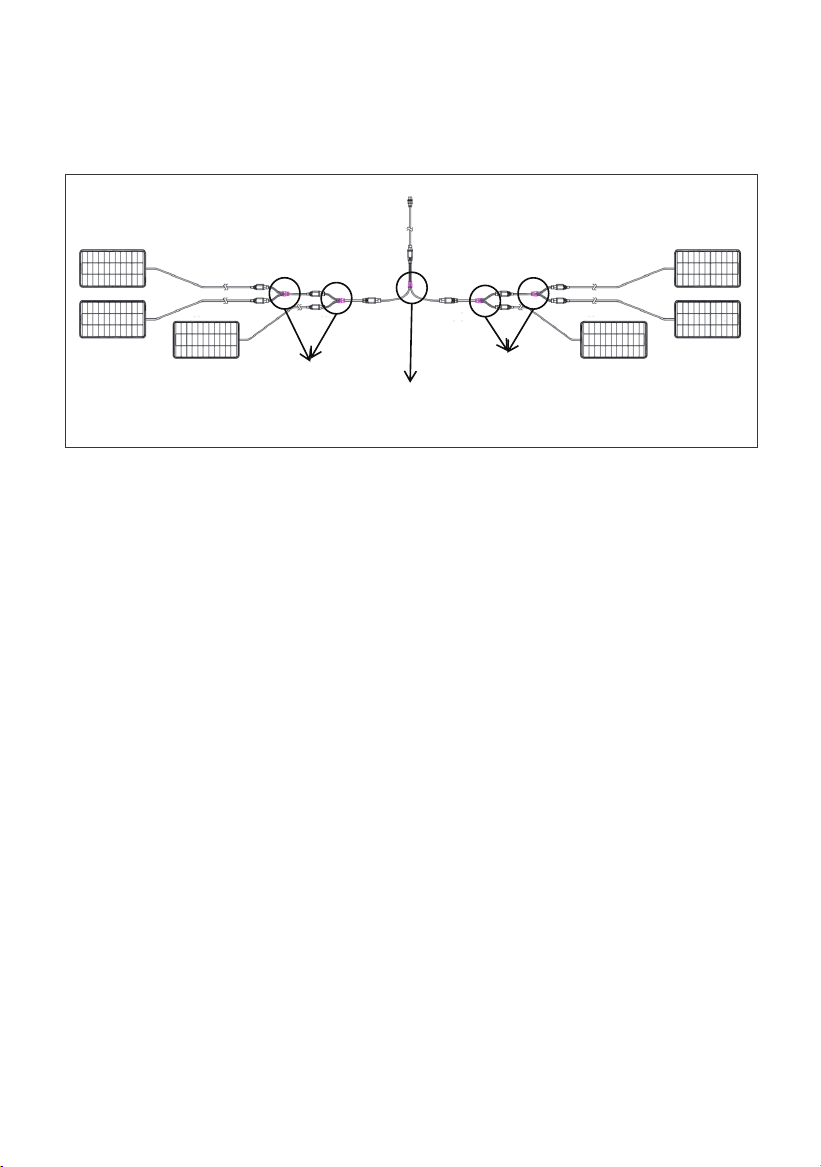
4) Applicable models: Explorer 2000 Plus/Explorer 2000 Pro/Explorer 3000 Pro
A single DC input port supports a maximum of 6 SolarSaga 100 Prime panels in series and parallel
combination. The Explorer 2000 Plus/Explorer 2000 Pro/Explorer 3000 Pro supports up to 12
SolarSaga 100 Prime panels. The connection diagram is as follows:
JA-SC01A
JA-PC01A
JA-SC01A