1
3. Binding ......................................................................... 2
4. Telemetry ....................................................................... 3
5. Working Modes ................................................................... 4
6. Firmware Update ................................................................. 7
7. Antenna Installment ............................................................. 7
8. RSSI Testing .................................................................... 8
9. Subsidiary ID ................................................................... 9
10. R16F Specifications ............................................................ 9
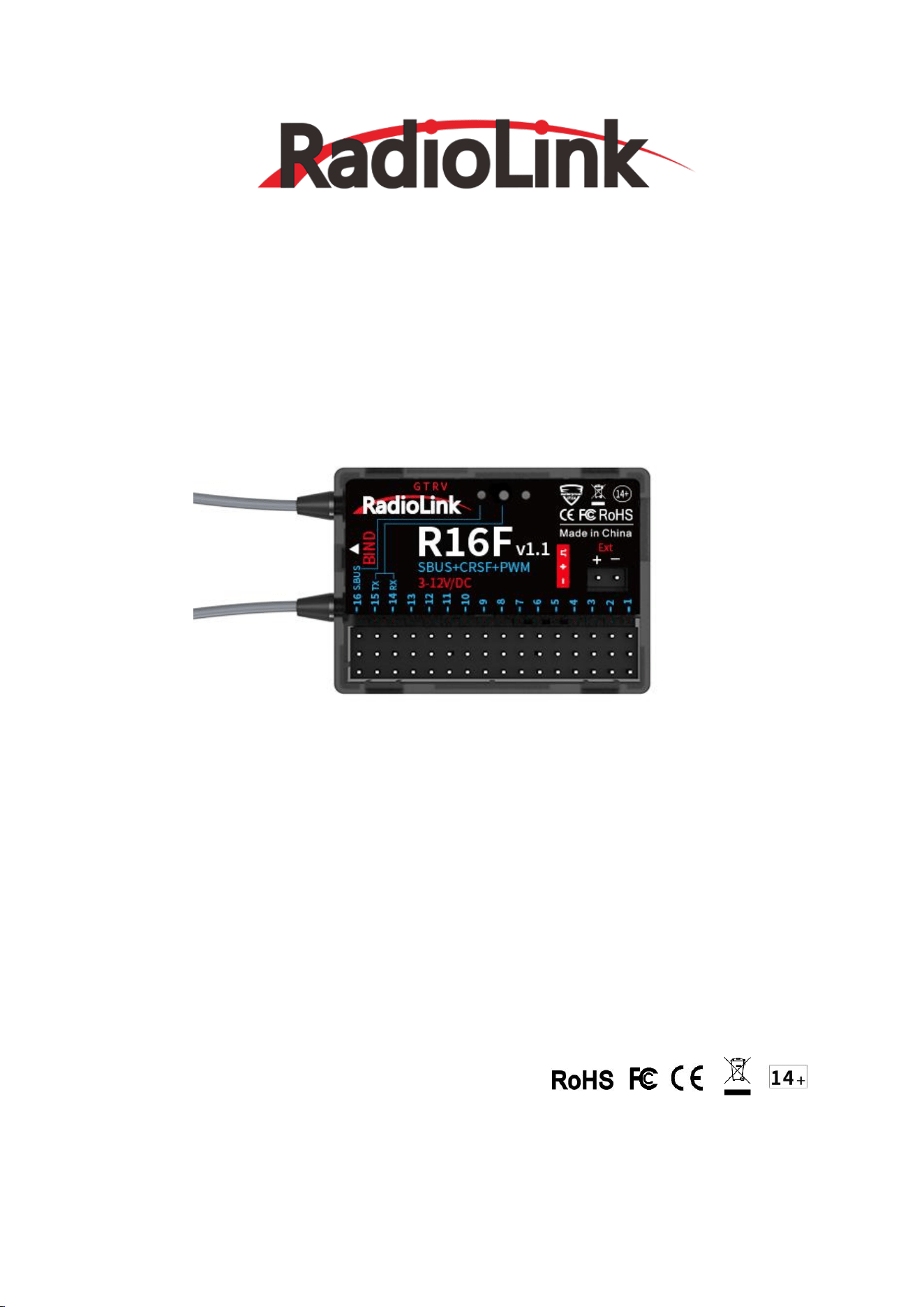
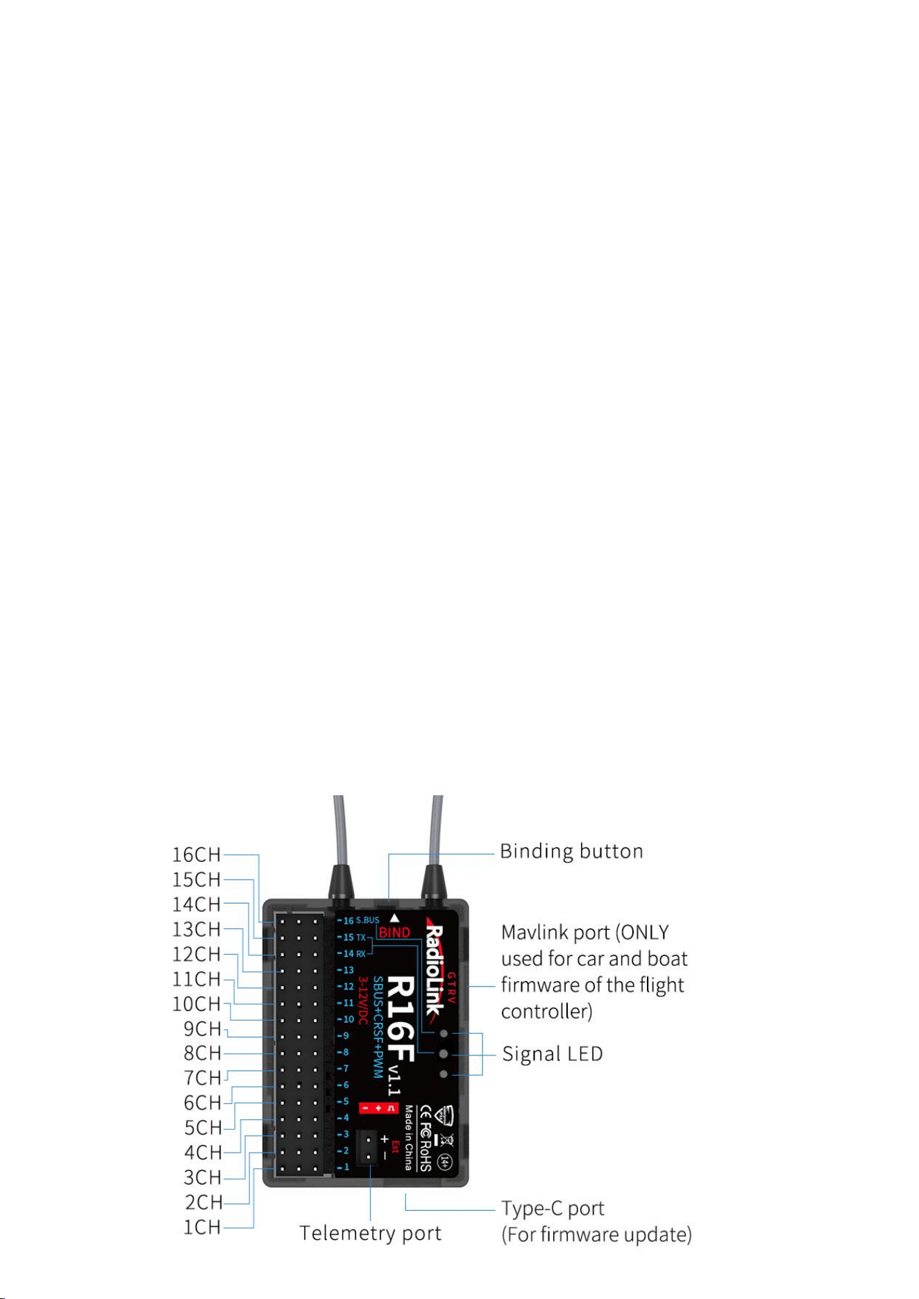
1. R16F Introduction
RadioLink R16F, 16-channel receiver, with real-time built-in telemetry supported, 2.4G FHSS spread
spectrum algorithm and 67-channel pseudo-random frequency hopping, supports PWM, SBUS and CRSF signal.
It is splash-proof, high voltage servo supported and can get the new functions by updating the firmware.
R16F is compatible with RadioLink T16D/T12D/T8FB/T8S/RC8X/RC6GS V3/RC4GS V3/RC6GS
V2/RC4GS V2/RC6GS/RC4GS transmitters.
2
Note:
1. For the function of Mavlink port, please refer to Bait Boat function of T16D/T12D transmitter.
2. Please do the following safety check before operating your model:
(1) RSSI test (Received Signal Strength Indicator). For test method, please refer to the manual
Chapter 8. RSSI Testing.
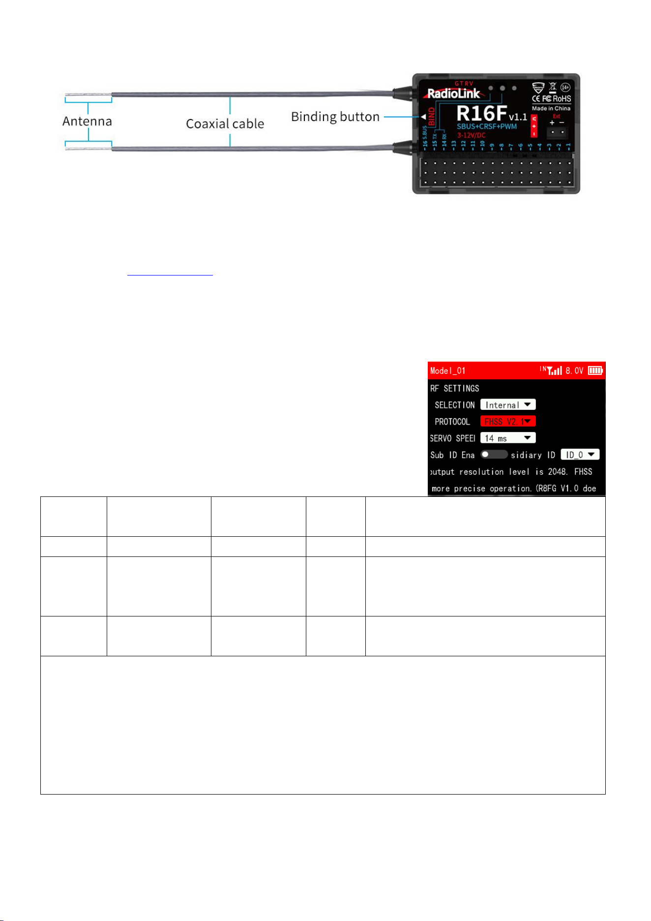
(2) Antenna inspection: The gray line on R16F is coaxial cable, while the transparent line with a
length of about 4-5 centimeters at the top is antenna. If the transparent line is broken or damaged,
it will directly affect the control distance. If any abnormality is found, please replace the
receiver antenna in time.
2. Receiver Protocol Selection
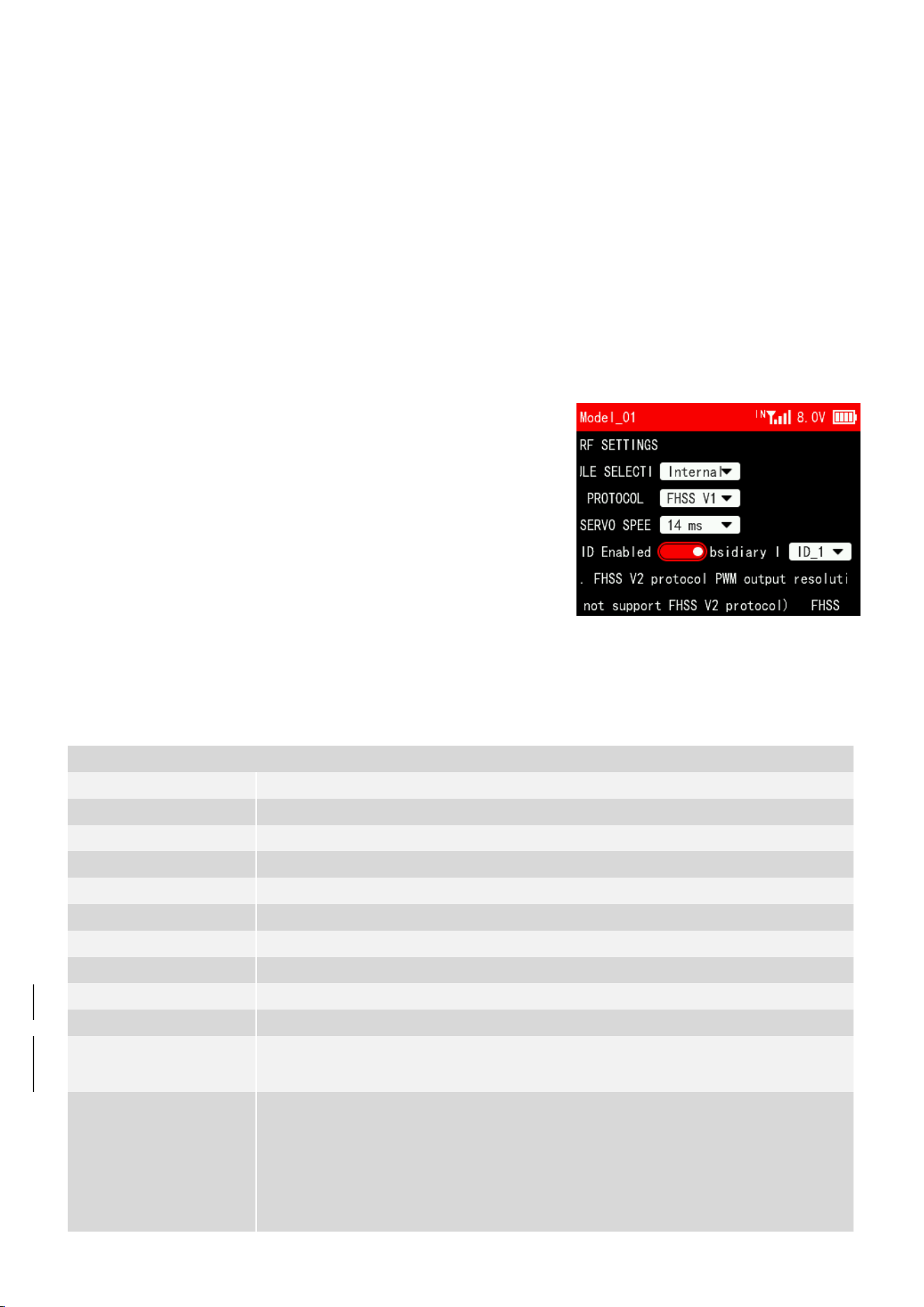
If R16D is used together with T16D/T12D, please select receiver
protocol in the transmitter. Enter Transmitter Setting--RF
SETTING,and then select the protocol. R16F supports FHSS V1, FHSS
V2 and FHSS V2.1 protocol. It is recommended to select FHSS V2.1
protocol. For the differences of the protocols, please refer to
the table below:
Protocol
PWM Output
Resolution
Servo Speed
Channel
Number
Compatible Receiver
FHSS V1
2048
14ms
8
All receivers compatible with T16D/T12D
FHSS V2
4096
3ms/4ms/14ms
available
8
R16F, R12F, R8FGH, R8FG V2.1, R4FGM V2.1,
and R8FG and R4FGM receivers with a factory
date of 2023/4/26 or later
FHSS V2.1
4096
3ms/4ms/14ms
available
16
R16F、R12F
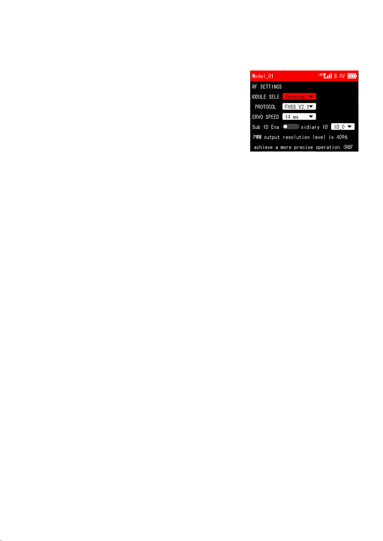
Notes:
1. FHSS V2 and FHSS V2.1 protocol PWM output resolution level is 4096, so they can achieve a more
precise operation.
2. FHSS V2 and FHSS V2.1 support 8 channels. When using R16F and 12F, if FHSS V1 or FHSS V2 protocol
is selected, only 8 channels are available on the receiver.
3. After switching protocols, please re-bind the receiver and the transmitter.
4. If digital servo is used, you can select 3ms or 4ms servo speed.
3. Binding
Each receiver has an individual ID code and must bind with transmitter before using. When the binding
3
is done, the ID code will be stored in the transmitter and there is no need to rebind. Therefore, when
a new R16F is purchased, binding needs to be done in order to work with transmitter.
Binding steps:
(1) If T16D/T12D/RC8X transmitter is used, select the receiver
protocol in the transmitter. For T16D/T12D transmitter, you also
need to make sure you have select Internal for MODULE SELECTION,
as shown on the right. (Please refer to Chapter 2. Receiver
Protocol Selection)
Note: If you are using a transmitter other than 16D/T12D/RC8X,
such as RC6GS/RC4GS/T8S/T8FB, etc., go to step 2 directly.
(2) Put the transmitter and the receiver close to each other (about 60 centimeters). Note: The close
distance of the transmitter and receiver may cause signal block, which leads to unsuccessful binding
or signal loss.
(3) Turn on the transmitter and the receiver, and the LED of R16F will start flashing slowly.
(4) There is a black binding button (ID SET) on the side of receiver. Press the button for more than
1 second and release, the LED will flash quickly, indicate binding process is ongoing.
(5) When the LED stops flashing and is always on, binding is complete and there will be a signal tower
shown on top of the LCD screen of the transmitter. If not succeed, the LED will keep flashing slowly
to notify, repeat the above steps.
Note:
a. When the transmitter and receiver are powered on, if binding fails or the signal is lost, the
LED of the receiver will keep flashing to notify.
b. The close distance between the transmitter and receiver may cause a signal block, which leads
to unsuccessful binding or signal loss. After the binding is successful, if the transmitter
and receiver are too close (for example, within 60 centimeters), the signal may also be lost
because of signal block. Bring the transmitter and the receiver farther apart, the signal loss
will disappear automatically.
4. Telemetry
R16F supports real-time built-in telemetry, including signal strength, RSSI value, receiver
voltage and model battery voltage. When R16F is connected to the flight controller and using the bait
boat function of T16D/T12D, the fishing spot information such as fishing spot name, latitude, and
longitude, distance, heading, the number of GPS satellites received, etc. will be displayed on the
transmitter screen.
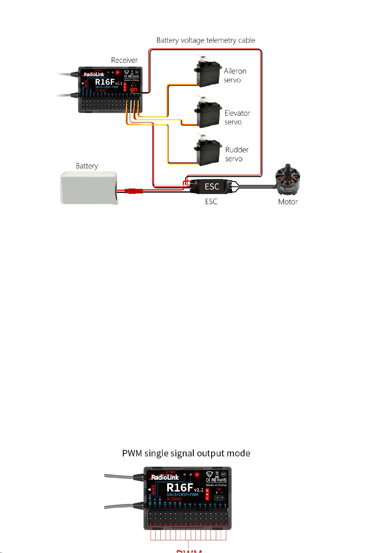
Connect one end of the telemetry cable to the R16F telemetry port, and the other end to the ESC
to return the power battery voltage. Please refer to the below picture for connection of the telemetry
cable:
4
Attention:
(1) Reverse polarity protection circuit design for all 16 channels of R16F ensures vital components
are protected from a reverse polarity connection. But the JST connector which packed with R16F
for connect to battery cannot reverse polarity connect, or it will lead to the wrong voltage value
telemetry.
(2) Ext port is only used to model voltage telemetry. It can not be used to power the receiver.
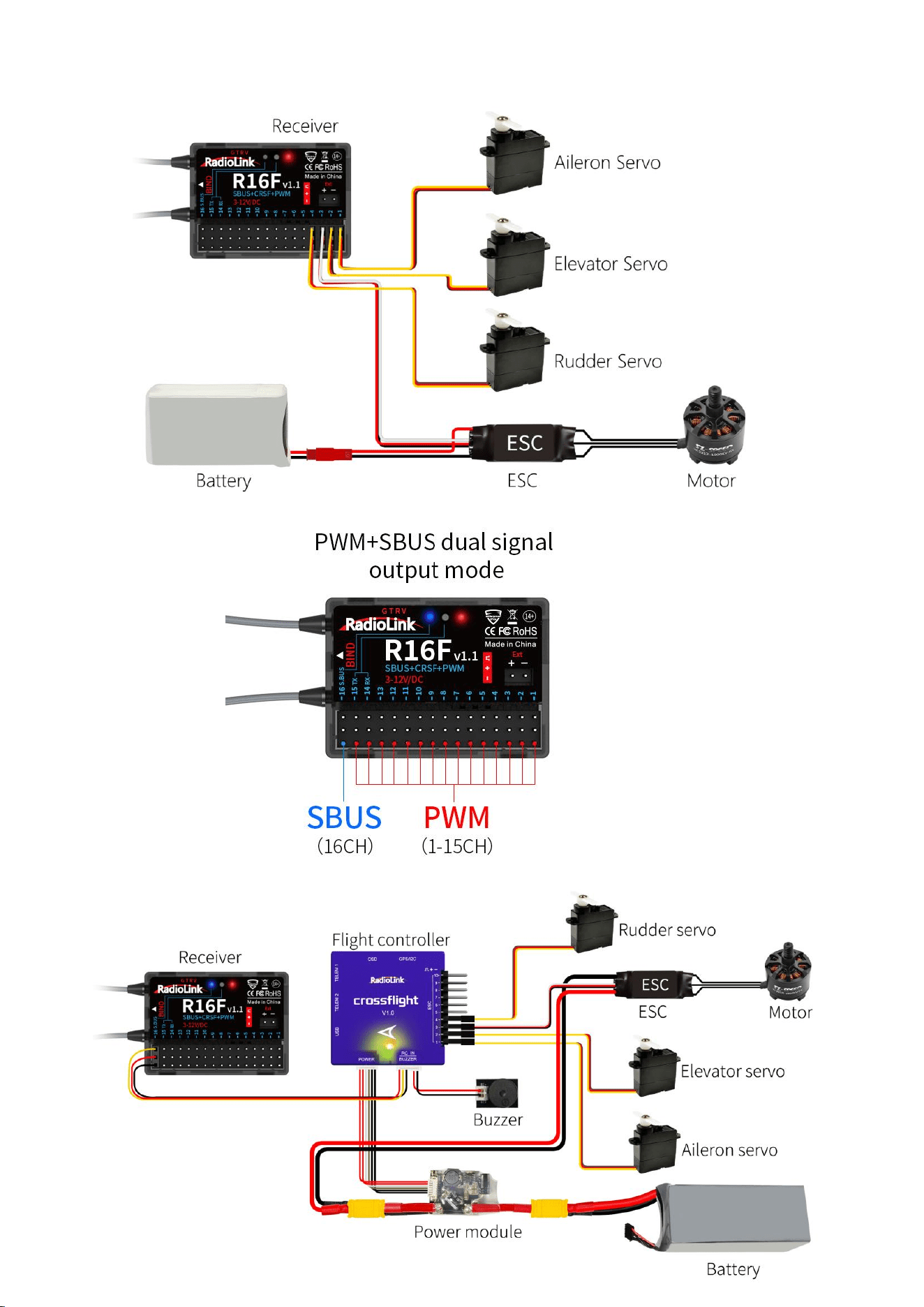
5. Working Modes
R16F supports three signal outputs: PWM, SBUS and CRSF. It has four working modes in total.
R16F working modes setting:
(1) Turning on/off the SBUS: Short press the binding button once to turn on/off the SBUS. Blue
LED indicates the SBUS is turned on, and channel 16 outputs SBUS signal.
(2) Turning on/off the CRSF: Short press the binding button twice within 2 seconds to turn on/off
the CRSF. Green LED indicates the CRSF is turned on. Channel 14 receives RX and channel 15
outputs TX.
Introduction of the four working modes:
1) PWM working mode
Red LED always on indicates PWM signal output, 16 channels in total.
5
2) PWM+SBUS working mode
Red and blue LED always on indicates PWM+SBUS signals output.
CH1 to CH15 output PWM signal output while CH16 outputs SBUS signal.
6
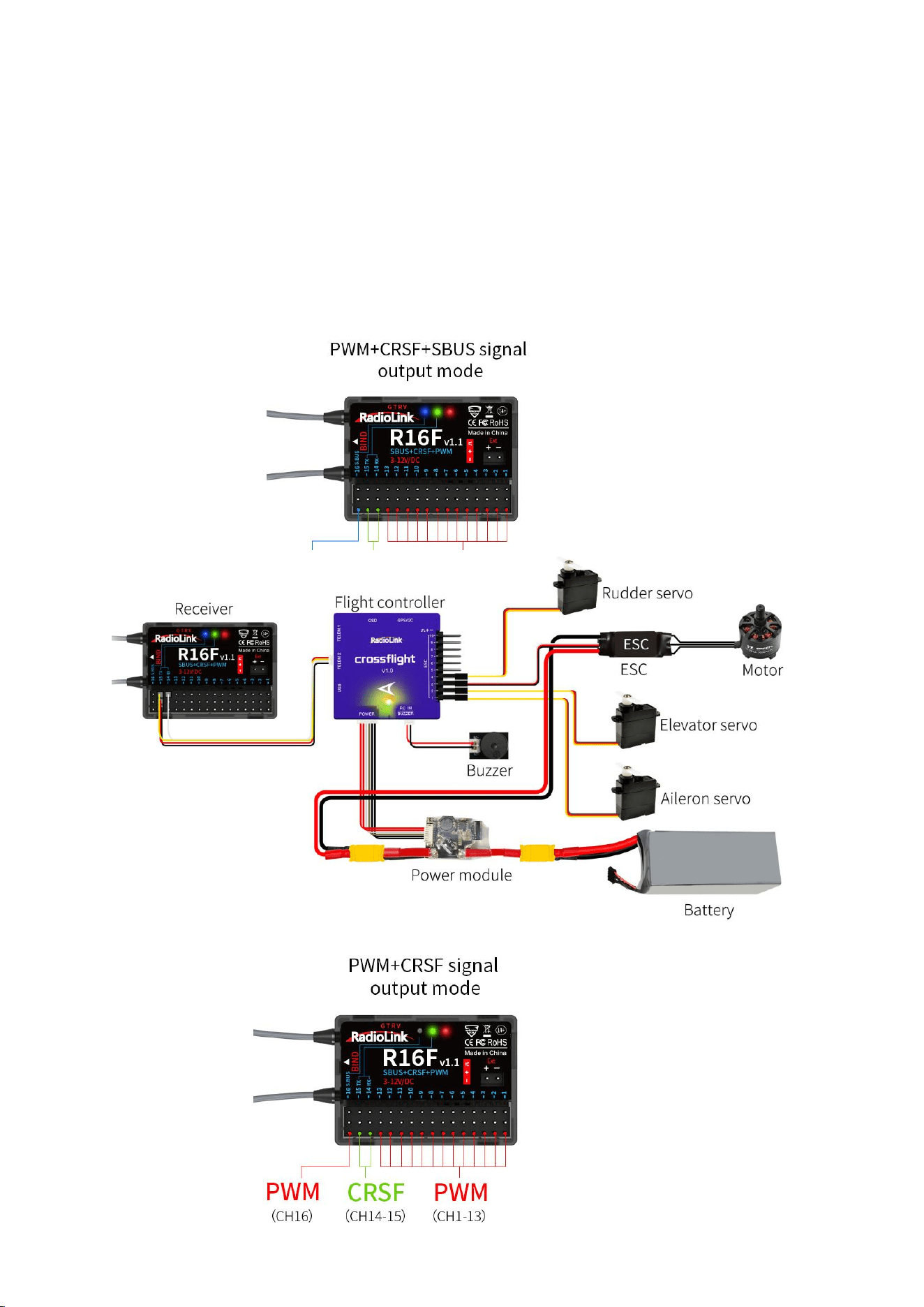
3) PWM+CRSF+SBUS working mode
Red, green, and blue LED always on indicates PWM+CRSF+SBUS signals output.
CH1 to CH13 output the PWM signal, CH 14 receives RX, CH15 outputs TX, and CH16 outputs the
SBUS signal.
Note: R16F comes with the cable to connect to CrossFlight TELEM2 in the picture.
4) PWM+CRSF working mode
Red and green LED always on indicates PWM+CRSF signals output.
CH1 to CH13 output the PWM signal, CH 14 receives RX, CH15 outputs TX, and CH16 outputs the
PWM signal.
7
Note: R16F comes with the cable to connect to CrossFlight TELEM2 in the picture.
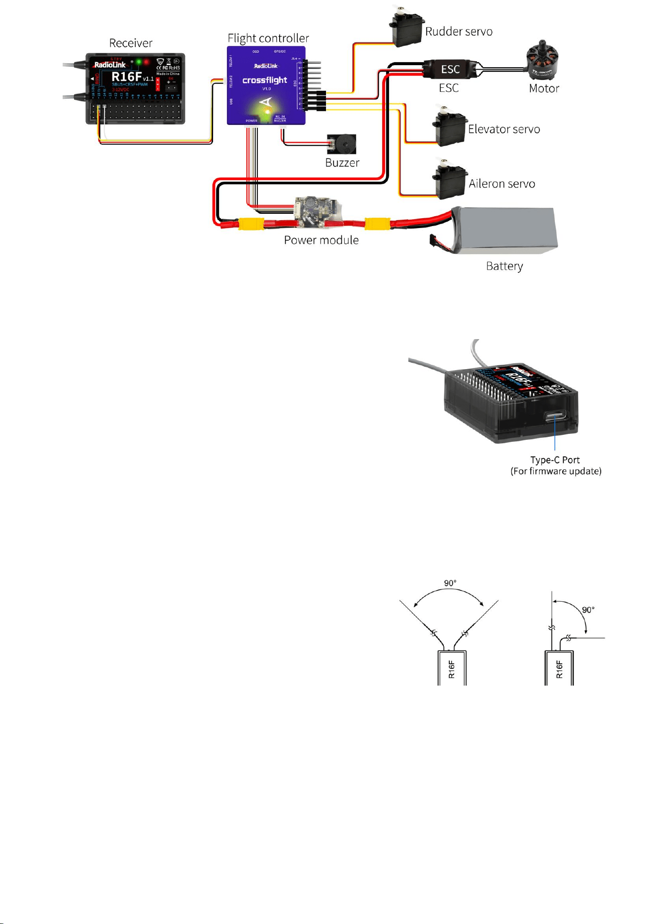
6. Firmware Update
R16F supports firmware upgrade. The steps for firmware
upgrade are as follows:
(1) Plug a Type-C cable into the Type-C port of R16F.
(2) Press and hold the binding button of R16F.
(3) Plug the other end of the Type-C cable into the computer
and release the binding button.
(4) The LED of the receiver is on, and a USB flash drive
appears on the computer.
(5) Copy and paste the new firmware of R16F into the USB flash drive to complete the update.
7. Antenna Installment
It is important to install the receiver antenna correctly on the model, because wrong receiver
antenna installation will cause poor signal quality.
How receiver antenna installation affects signal quality?
Here are the common mistakes when installing the antennas:
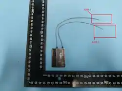
(1) The two antennas of the receiver CANNOT overlap, because
they will interfere with each other. Keep the two antennas
at a 90-degree angles. (As shown on the right)
(2) Antennas should NOT be placed near metal objects, because reflection of the conductor panel will
drastically worsen the signal.
(3) Do NOT keep antennas parallel to the ground. It should be placed vertically to the ground.
(4) Big models may contain metal parts that influence signal emission. In this case. antennas should
be positioned at both sides of the model to ensure the best signal status in all circumstances.
(5) Antennas should be kept away from metal conductor and carbon fiber at least half inch away and
no over bending.
(6) Keep antennas away from motor, ESC or other possible interference sources.
(7) Sponge or foam material is advised to use to prevent vibration when installing receiver.
8
(8) Receiver contains some electronic components of high-precision. Be careful to avoid strong
vibration and high temperature.
(9) Special vibration-proof material for R/C like foam or rubber cloth is used to pack to protect
receiver. Keeping the receiver in a well sealed plastic bag can avoid humidity and dust, which
would possibly make the receiver out of control.
Refer to the following link to view the guide on receiver antenna installation:
https://www.radiolink.com/newsinfo/886600.html
8. RSSI Testing
If the control distance is short, please refer to this instruction to test the RSSI between the
transmitter and receiver. This instruction will introduce the test procedure of the transmitter RSSI
value and the solution to the abnormal RSSI value.
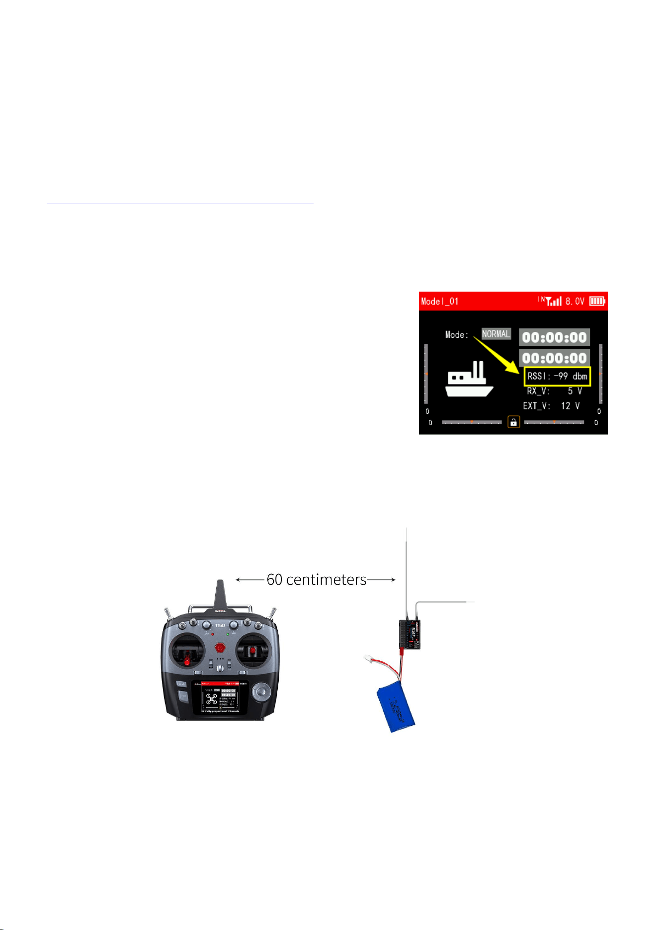
(1) Turn on the transmitter and power on the receiver at the same
time, and then the transmitter and receiver will be connected
(if not connected, you need to bind again). The signal tower
appears on the transmitter interface, indicating that the
binding is successful. The value of RSSI will appears on the
home page, and the RSSI value will keep changing according to
the distance between the transmitter and the receiver. (As
shown on the right)
(2) Make the receiver antenna and transmitter antenna parallel. Keep transmitter apart from receiver
about 60 centimeters and both antennas straight. It is normal that RSSI value is within the range
of 0 to -30dBm. The closer the value is to 0, the stronger the signal is. (As shown below)
Abnormal signal strength solution:
Check whether the antennas of the receiver and transmitter are damaged. Most signal strength
degradation is caused by antenna damage. If it is damaged, the antenna needs to be replaced. If there
is no damage, you can test the transmitter and receiver for malfunctions by replacing the receiver.
If still cannot solve the problem, email to after_service@radiolink.com.cn to get support.
9
9. Subsidiary ID (Take T16D transmitter as an example)
RadioLink transmitters can bind with multiple receivers. When T16D and multiple receivers have
been bound successfully, and T16D and all successfully paired devices are turned on at the same time.
There are two ways to use them:
1. When Subsidary ID function is turned off, T16D can control multiple devices at the same time.
2. When Subsidary ID function is turned on, T16D can control the specified device according to
the selected Subsidary ID. T16D has 16 groups of Subsidary ID functions, and each ID corresponds to
a receiver. Set the Subsidary ID first. When all the devices are turned on, you can control one of
the devices through the Subsidary ID function. At this time, the other devices are on standby.
For example: Bind T16D with a truck and a car and turn all them on. First, use T16D to control
the car to run to the bucket of the truck, and then switch the receiver ID on the truck to drag the
car back to the destination.
Subsidary ID function setting steps:
1. Turn on Subsidary ID function. Then set the ID number
according to your models and then finish the binding and
parameters set for each receiver.
Once the Subsidary ID is turned on, the corresponding ID
number will be displayed on the main interface of T16D.
Note: You can assign a 2 position switch or 3 position switch
to change subsidiary ID number in T16D/T12D transmitte. For
more details, please refer to the CONDITION function of T16D/T12D.
R16F Specifications
R16F Receiver
Dimension
45*32*15mm(1.77"*1.26"*0.59")
Weight
17g (0.6oz)
Channel
16 channels
Operating Voltage
3~12V
Operating Current
50±10mA@5V
Antenna Length
205mm (8.07”)
Signal Output
SBUS+CRSF+PWM
Output Frequency
2.4GHz ISM band(2400MHz~2483.5MHz)PWM&PPM&SBUS
Spread Spectrum
FHSS 67 channels pseudo-random frequency hopping
Adaptable Models
Rotary Wing/Fixed-wing/Glider/Multicopter/Car/Boat/Robot
Control Distance
4000 meters in the air(Maximum range is tested in an unobstructed area free
of interference)
Telemetry
Real-time built-in telemetry of the model battery voltage, RSSI, and
receiver voltage. R16F has built-in data transmission functions. When
connected to the flight control, they can send back information such as
latitude and longitude, distance, number of satellites, heading, and other
information in real-time.
10
Technical Support Here
Contact RadioLink RL R16F User Manual R16F Tutorials
via Facebook Messenger
If the above communication cannot solve your problem, you can also send emails to our technical
support: after_servic[email protected].cn This content is subject to change. Download the latest version
from https://www.radiolink.com/r16f_manual
Thank you again for choosing RadioLink product.
FCC Statement
This equipment has been tested and found to comply with the limits for a Class B digital device, pursuant to Part 15
of the FCC Rules. These limits are designed to provide reasonable protection against harmful interference in a
residential installation. This equipment generates uses and can radiate radio frequency energy and, if not installed
and used in accordance with the instructions, may cause harmful interference to radio communications. However,
there is no guarantee that interference will not occur in a particular installation. If this equipment does cause harmful
interference to radio or television reception, which can be determined by turning the equipment off and on, the user
is encouraged to try to correct the interference by one or more of the following measures:
-- Reorient or relocate the receiving antenna.
-- Increase the separation between the equipment and receiver.
-- Connect the equipment into an outlet on a circuit different from that to which the receiver is connected.
-- Consult the dealer or an experienced radio/TV technician for help.
Upgrade Online
with a Type-C cable (for data transmission) connecting the R16F to the
computer, the latest cutting-edge functions can be easily added without
any extra device.
EXT Battery Input
1S-8S(3.0-33.6V)
Response Latency
3ms, 4ms, 14ms can be selected
Water Splash Proof
The waterproof grade is IPX4
Operating Temperature
-30° to 85° C
Compatible
transmitter
T16D/T12D/T8FB/T8S/RC8X/RC6GS V3/RC4GS V3/RC6GS V2/
RC4GS V2/RC6GS/RC4GS

11
Any Changes or modifications not expressly approved by the party responsible for compliance could void the user's
authority to operate the equipment.
This device complies with part 15 of the FCC Rules. Operation is subject to the following two conditions:
(1) This device may not cause harmful interference, and
(2) This device must accept any interference received, including interference that may cause undesired operation.
Device compliance with FCC RF exposure requirement, and can working operation without any restriction