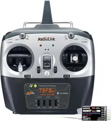
AT10II
Quick Start Guide
(
Helicopter/Fixed-wing/Glider/Multirotor/Car/Boat/Robot
)
12 channels transmitter
CE FCC RoHS
1
Packing List
Safety Precautions
Never operate your model during adverse weather conditions. Poor visibility can cause
disorientation and loss of control of your model.
Never use this product in a crowded and illegal area and strictly comply with the local
regulations.
Always ensure the trim levers at 0 and battery properly charged before connecting the
receiver.
Always check all servos and their connections prior to each run.
Multi-rotor must check whether the motor rotation direction is normal.
Always be sure about turning off the receiver before the transmitter.
The AT10II transmitter cannot be restored to factory settings, but the currently used model
can be reset in "BASIC MENU"-"MODEL TYPE".
Please strictly abide by local laws and regulations and use it safely!
This product is not a toy and is NOT suitable for children under the age of 14. Adults should
keep the product out of the reach of children and exercise caution when operating this product in
the presence of children.
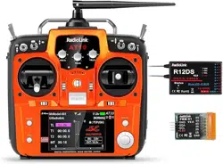
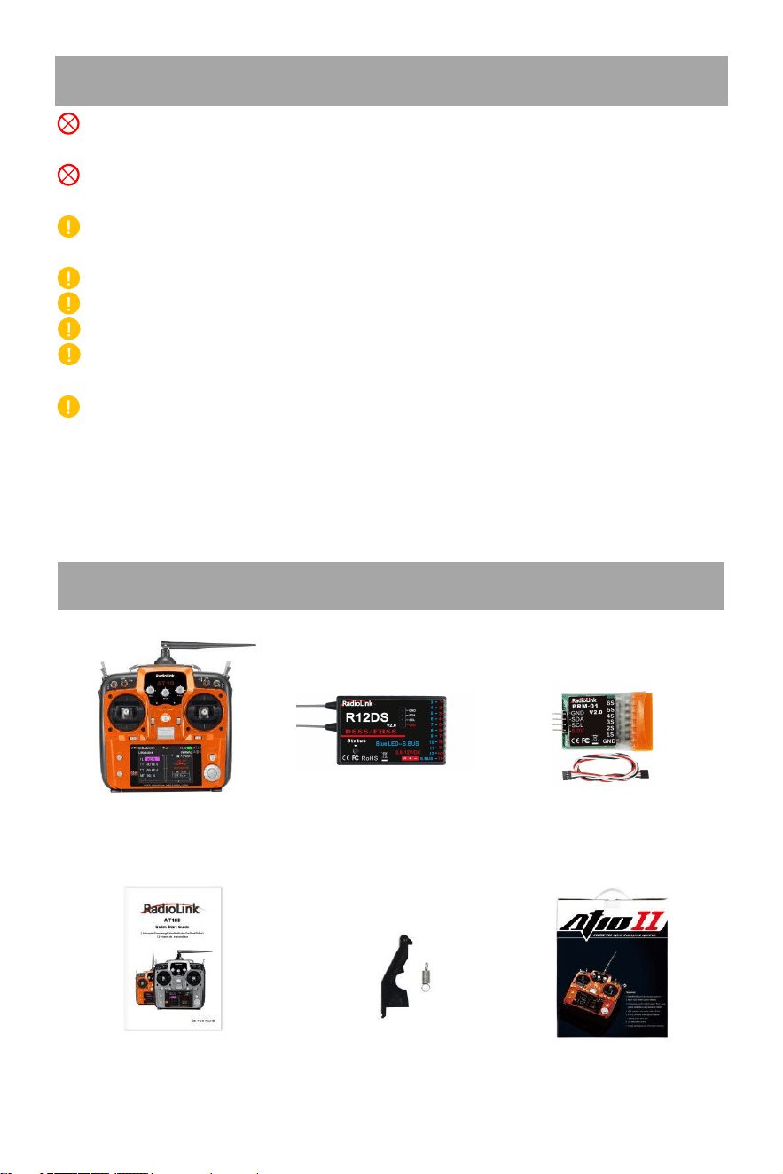
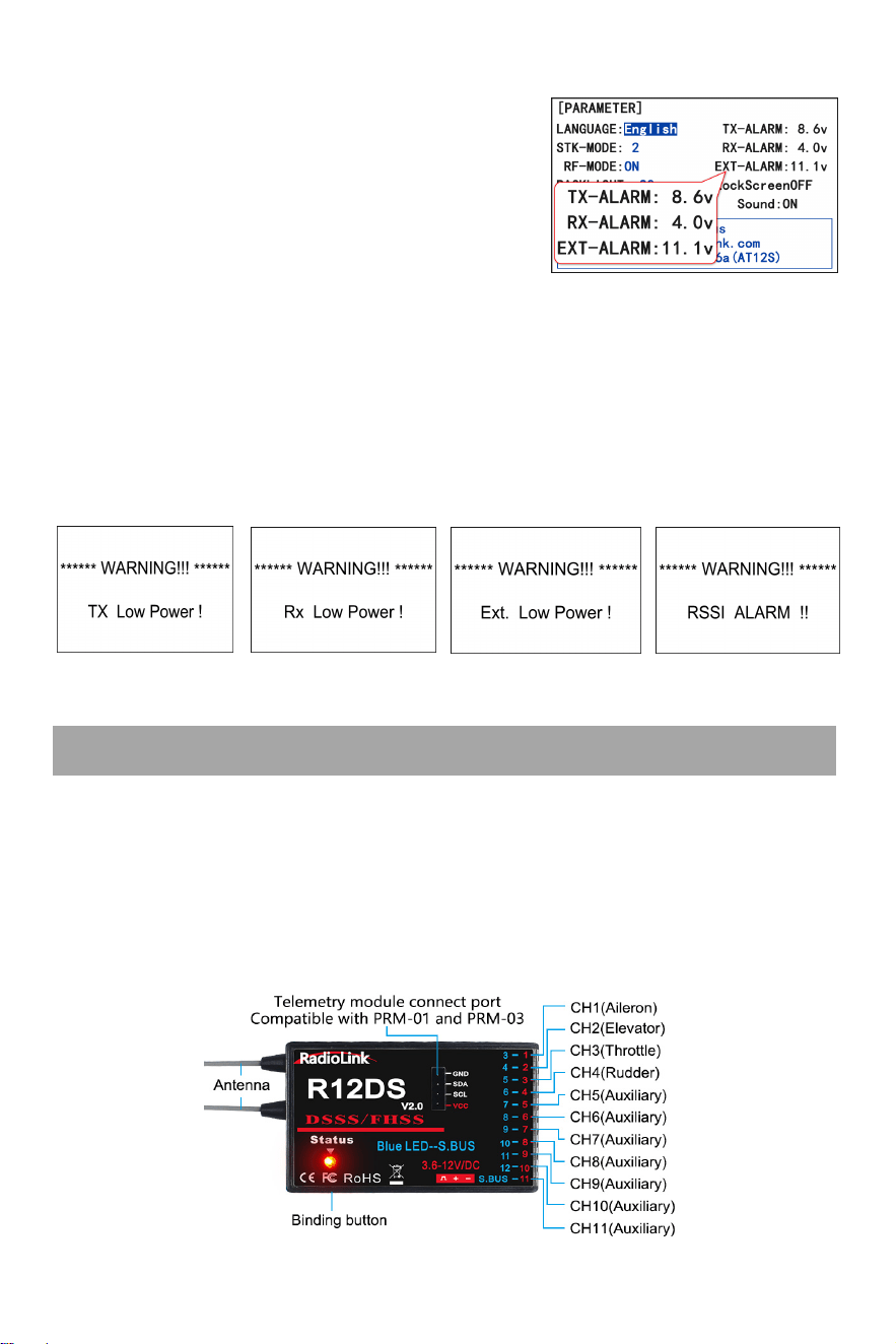
AT10II Transmitter×1 R12DS Receiver×1 PRM-01 Telemetry Module×1
Quick Start Guide×1 THR Return Accessories×1 Packing Box×1
2
S
p
ecifications
AT10II Transmitter
Size 180*95*220mm (7.1”*3.7”*8.7”
)
Weight 0.95kg(2.1 lb)
Channel Quantity 12 (all twelve channels can be customized)
Control Range
More than 4000 meters in the air, and 2000 meters on the ground.
The actual control distance depends on the environment.
Operating Current <105mA
Operating Voltage
7.4
~
15.0V (8pcs AA battery, a 2S-4S LiPo or 18650 Lithium
battery, Li-ion, NiMH or NiCad battery)
ACPR >38dbm
Transmitter Power <100mW (20dbm)
Frequencies Band 2.4GHz ISM band (2400MHz~2483.5MHz)
Modulation Mode QPSK
Bandwidth 5.0MHz
Spread Spectrum Mode DSSS&FHSS
Storage Model Quantity 15
Battery Box Size 115*32*30.5mm(L*W*H=4.53"*1.26"*1.2")
Low Voltage Alarm Support. Voltage alarm can be customized
Signal Output PWM/SBUS/PPM
Simulator Mode Yes, with the radio frequency off to save battery power
Screen 3.5 inches 16 colorful screens, 320*480 pixels
Operating Temperature -20° to 85° C (-4° to 185° F)
Adaptable Models
include all 120-degree and 90-degree swash-plate helicopters, all fixed
wings, gliders, multirotor, RC cars, RC boats, and Robot
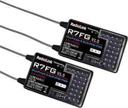
Compatible Receivers R12DS(Standard), R12DSM, R9DS, R6DS, R6DSM
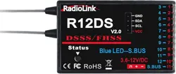
R12DS Receiver
Size 50*32*14.5mm (1.97"*1.24"*0.57")
Weight 14g (0.49oz)
Antenna Length 215mm (8.46")
Channel Quantity
11 channels for PWM signal output;
12 channels for SBUS&PWM signal output
Control Range
More than 4000 meters in the air, and 2000 meters on the ground. The
maximum range tested in unobstructed areas free of interference and
depends on the environment.
Operating Current 38~45mA@5V
Operating Voltage 3.6-12V
Signal Output PWM(red LED) and PWM&SBUS(blue/purple LED)
Section Precision 4096, 0.25us per section
Compatible extended
telemetry module
Connect PRM-01 for model voltage telemetry.
Connect PRM-03 and flight controller crossflight, PIXHAWK, Mini Pix,
and TURBO PiX, APM for OSD information telemetry
Compatible
Transmitters
AT10II/AT10/AT9S Pro/AT9S/AT9
3
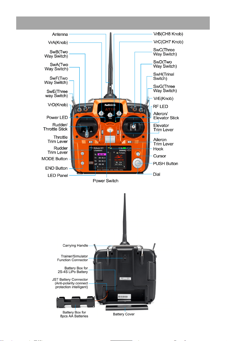
Transmitter AT10II
Note: The picture above takes the left-hand throttle as an example.
4
Basic Operations
Note
:
For normal functions, short press the PUSH button to confirm, but when modifying the
"MODEL SEL" and "MODE TYPE”, long press the PUSH button for 1 second to confirm.
Aileron/Elevator/Throttle/Rudder Stick controls 1 to 4 channels by default. Set STK-MODE
in PARAMETER menu. If you set the STK-MODE to “-” and then the AUX-CH in BASIC
MENU, you can assign other switches to control channel 1 to channel 4.
Three VR knob switches on the front and two VR slider switches on the side meet the needs
of pan/tilt control, and the functions of these switches can be customized.
AT10II has 4 two-way switches, 3 three-way switches and a reset switch. Function of all
switches can be customized. For details, please refer to the detailed manual of AT10II
www.radiolink.com/at10ii_manuals.
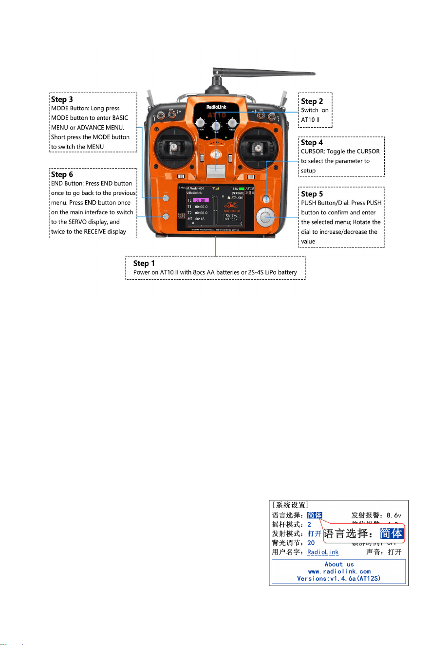
Basic Settings
1. Language Settings: Long press the MODE button to enter
the menu, if the language is displayed as Chinese, please
rotate the PUSH button to move the cursor to
PARAMETER(
系 统 设 置
), short press the PUSH button to
enter the setting interface, and change the language from
Chinese (
语言选择
:
简体
) to English.
5
R12DS Receiver
Receiver Low Powe
2. Alarm Settings: The low voltage alarm of the transmitter, receiver, model battery and
RSSI(Received Signal Strength Indicator) alarm can be
customized on AT10II. The factory low voltage alarm is 8.6V
for transmitter; 4.0V for receiver; 11.1V for model battery.
When the voltage is lower than the set alarm value, the
transmitter will send out an alarm (See pictures below), and
the low battery alarm can be set according to the actual voltage of the battery to avoid battery
over-discharge.
Setting steps: BASIC menu - PARAMETER - TX-ALARM/RX-ALARM/EXT-ALARM. (Voltage
alarm reference: 2S lithium battery -7.4V; 3S lithium battery -11.1V; 4S lithium battery -14.8V.)
The RSSI alarm is turned off by default. The alarm value can be customized. When the signal
strength is lower than the set alarm value, the transmitter will send out an alarm (See picture
below). Setting steps: BASIC menu - SYSTEM - RSSI ALM.
Radio Low Power r Model Low Power RSSI Low Alarm
Working Modes
R12DS, with 2.4G DSSS&FHSS spread spectrum technology, is a 11-channel receiver when
working with PWM signal output (red LED) or a 12-channel receiver when with SBUS&PWM
signal output (purple/blue LED).
1. PWM Signal Mode:Red LED indicates PWM signal output, 11 channels totally.
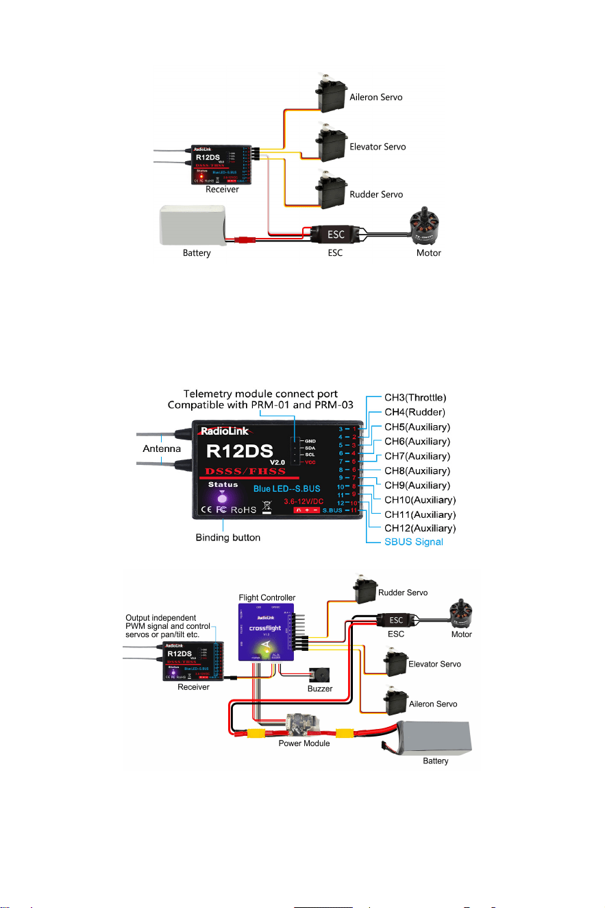
6
Note: Fixed wing equipped with flight controller is taken as an example
2. SBUS&PWM Signal Mode: Blue/purple LED indicates SBUS&PWM signal output at the same
time with 12 channels totally. The eleventh channel outputs SBUS signal while the original CH1
outputs CH3 PWM signal and original CH2 to CH10 output CH4 to CH12 PWM signal at the
same time.
.
Switch Signal Mode:Short press binding button (ID SET) twice within 1 second, the working
mode will be switched.
7
Receiver Mode
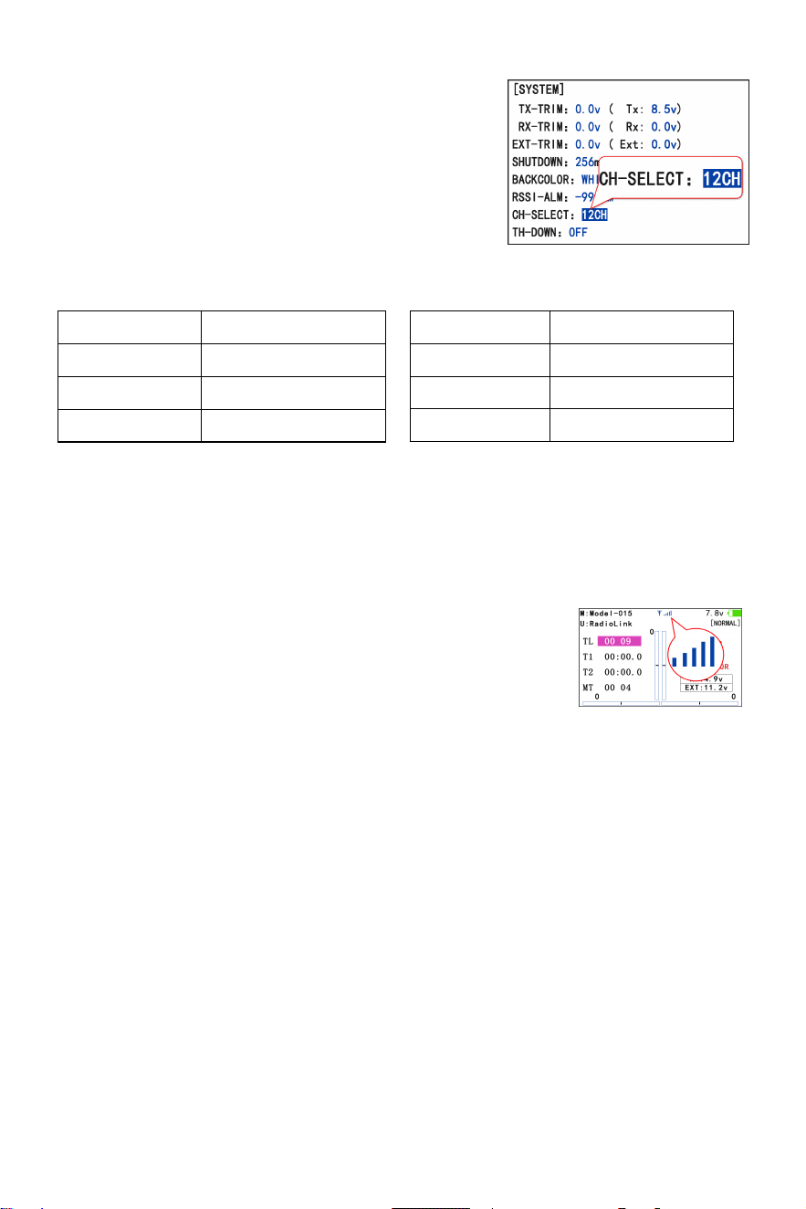
Channel Settings
AT10II is a 12-channel transmitter. The channel is selected
as 12 channels by default (See the right picture). When using
the standard packed R12DS receiver, there is no need to
modify the settings; but when using R9DS, R6DS or R6DSM
receiver, channel of AT10II should be selected as 10
channels, 10CH. For the channel selection of AT10II when using different receivers, please refer
to the figure below:
l AT10II CH-SELECT
R9DS 10CH
R6DS 10CH
R6DSM 10CH
Setting steps: BASIC menu - SYSTEM - CH-SELECT.
Note: If the channel of AT10II is selected incorrectly, the servo may vibrate all the time.
Binding Steps:
1. Put the transmitter and the receiver close to each other (about 30 centimeters).
2. Power on AT10II and R12DS, the LED of R12DS will be on.
3. There is a black binding button (ID SET) on the side of receiver. Press the button for more than
one second and release, the LED of the receiver will flash, meaning binding process is ongoing.
4. When the LED stops flashing and is always on, binding is complete. There will be a signal
tower shown on top of the LCD screen of the transmitter. If not succeed, the LED will keep
flashing slowly to notify, repeat the above steps.
Note:Since RadioLink radio control systems are not open sourced, RadioLink transmitters are
ONLY compatible with RadioLink receivers
Binding
AT10II and R12DS have already finished binding by default. Turn on AT10II and R12DS, the
signal tower will be displayed on the top of the screen (See the right
picture), which means the transmitter and receiver have finished
binding.
If you purchase a new R12DS receiver separately, you need to bind the receiver to the
transmitter. Each receiver has an individual ID code. When the binding is done, the ID code will
be stored in the transmitter and there's no need to rebind.
.
Receiver Model AT10II CH-SELECT
R12DS 12CH
R12DSM 12CH
8
Installment of Antenna
1. Receiver Antenna Installment
(1) Please test RSSI (Received Signal Strength Indicator) before operating models. For
the right, or the effective control range will reduce.
(4) Big models may contain metal parts that influence signa
methods on how to test it, please refer to https://www.radiolink.com/newsinfo/477894.html
(2) If the antenna of the receiver is damaged, replace it with a new antenna or receiver in time.
(3) Keep antennas as straight as possible and 90° as shown on
l
emission. In this case, antenna should be positioned at one side of the model to ensure the
best signal status in all circumstances.
(5) Antennas should be kept away from metal conductor and carbon fiber at least half inch
vibration and high temperature
away and no over bending.
(6) Keep antennas away from motor, ESC, or other possible interference sources.
(7) Receiver contains some electronic components of high-precision. Be careful to avoid strong
.
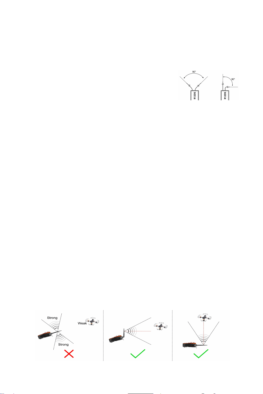
2. Transmitter Antenna Orientation
(1) The transmitter antenna orientation is adjustable. Please make sure that the antenna never
points directly at the model when flying as this may possibly decrease the receiver signal.
(See Picture 1 below).
(2) If the antenna is upright, the antenna signal mainly diverges in the horizontal direction,
which is beneficial to flying farther (See Picture 2 below); if the antenna is horizontal and
parallel to the ground, the signal mainly diverges in the vertical direction, which is beneficial
to fly higher (See Picture 3 below), so it is best to place the transmitter antenna
perpendicular to the connection line between the remote control and the aircraft during
flight.
(3) During the flight, please ensure that there is no obstruction between the transmitter antenna
and the receiver antenna to maximize the communication distance.
Picture 1 Picture 2 Picture 3
RSSI Testing
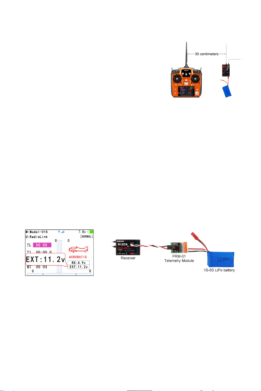
RSSI stands for Received Signal Strength Indicator. Before flight, always remember to do the
RSSI testing to avoid the possible unexpected signal loss.
1. Power on transmitter and receiver, keep them with the
distance of about 30 centimeters and both antennas straight
(See the right picture).
2. Enter the basic menu. Rotate the PUSH button to select
RECEIVE and press PUSH button to enter and check the
RSSI value. RSSI value between 0 to -30dBm is normal when the transmitter keeps about 30
centimeters distance from the receiver. The RSSI value is closer to 0, the signal is stronger
9
.
Real-time Built-in Telemetry
R12DS receiver integrates telemetry of signal strength and receiver voltage by default. It can
also realize the telemetry of model battery voltage or flight controller and GPS information when
used with RadioLink PRM-01 or PRM-03 telemetry module, and the telemetry information can be
displayed on the screen of AT9S Pro or AT10II transmitter.
Model battery voltage telemetry: When connecting R12DS to telemetry module PRM-01, the
model voltage will be displayed on the screen of AT10II (See picture below).
Note: PRM-01 is sold separately. PRM-01 only supports R9DS or R12DS receiver.
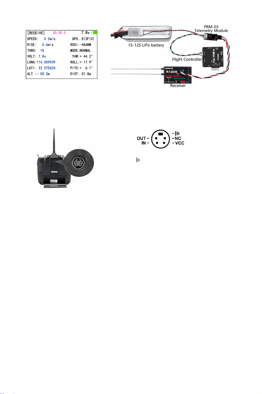
Flight controller and GPS information telemetry: When connecting R12DS to telemetry
module PRM-03 and flight controller, more information will be displayed on the screen of AT10II,
including the model battery voltage, speed, climb, throttle, longitude, latitude, altitude, GPS,
RSSI, flight mode, yaw, roll, pitch, and distance (See picture below).
Note: PRM-03 is sold separately. PRM-03 only supports R9DS or R12DS receiver, and it works
with flight controller crossflight, PIXHAWK, Mini Pix, TURBO PiX or APM.
10
Multiple Function Port
The simulator port of AT10II outputs PPM signal by default. So it can be connected to devices
that supports PPM input via simulator port such as head track, trainer cable, simulator etc..
Note:
1. Scan the QR code on the last page of the Quick Start Guide to view detailed video tutorials for
connecting AT10II to all the above devices.
2. Wireless trainer cable is sold separately. Please refer to the official website www.radiolink.com
for more information and purchase.
AT10II Tutorials
Please search Radiolink_official on YouTube to access RadioLink official channel and check all
the below video tutorials of AT10II. View the playlist of AT10II or search key words on our channel
for the function you want.
Firmware Update of AT10II
How to Reset AT10II
Test RSSI with AT10II Transmitter and Receivers
PROG.MIX Setting in AT10II
Connect TBS Crossfire with AT10II
AT10II Wireless Training Setup
AT10II FPV Drone Simulator Plug & Play
- :GND
-NC
:
No Output
-VCC:Voltage Output(7.4-15V)
-OUT:PPM Signal Out
-IN
:
RSSI Signal Input
11
How to make the 12CH AT10II transmitter work with 10CH receiver?
AT10II Mode 2(Left Hand Throttle) Change to Mode1(Right Hand Throttle)
Re-calibrate Joysticks of AT10II
AT10II Connects Telemetry Module PRM-01
AT10II Connects Telemetry Module PRM-03
TX Lower Power & Battery Supply of AT10II
AT10II Switch Backlight Color
Screen Lock Function on AT10II
Throttle Position Warning of AT10II
Replace the Antenna of AT10II
Use NAZA in SBUS with AT10II
Technical Support Here
Contact RadioLink RL AT10II User Manual AT10II Tutorials
via Facebook Messenger
If the above information cannot solve your problem, you can also send emails to our technical
support: after_service@radiolink.com.cn
This content is subject to change.
Download the manual of AT10II from https://www.radiolink.com/at10ii_manuals
Thank you again for choosing RadioLink product.