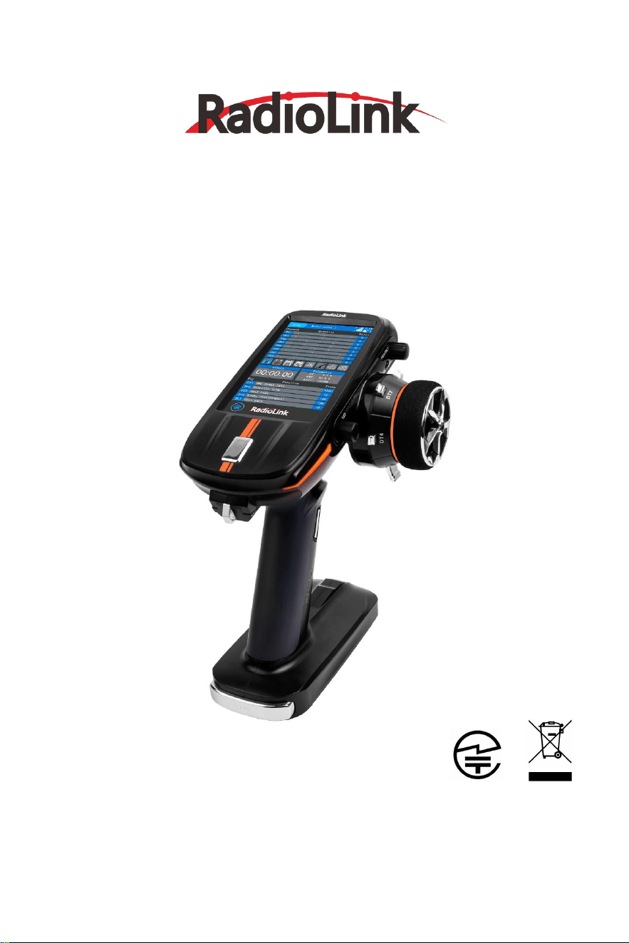
RC8X
Quick Start Guide
(
FHSS, 8-Channel Digital Proportional RC System
)
Adaptable to RC Cars/Boats/Robots
CE FCC RoHS
Note: For more detailed information on function setting of RC8X, please refer to RC8X
user manual on www.radiolink.com/rc8x_manual
For detailed information on how to update the firmware of RC8X, please refer to
www.radiolink.com/rc8x_firmware

RadioLink Electronic Limited
www.radiolink.com
Contents
Safety Precautions…………………………………………………................................................
3
Packing List………………………………………………….............................................................
3
Specifications……………………………………………….............................................................
..
4
RC8X Overview……………………………………………............................................................
6
Button Introduction
……………………………………..........................................................
7
Three Position Switch
……………………………….....................................................
7
Menu Introduction
………………………………..................................................................
8
Power on RC8X
........…………………….....................................................................
8
Icon Introduction
.......…………………….....................................................................
8
Basic Functions………………………………………….........................................................
9
Transmitter Low Voltage Alarm……………………........................................................
10
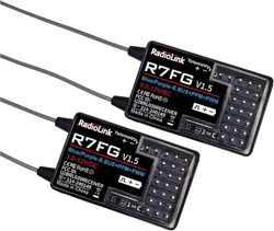
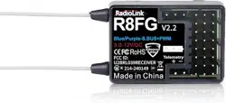
R8FG Introduction………………………………………...............................................................
10
Binding
……………………………………………….................................................................
..................
10
Receiver Setting……………………………………..............................................................
11
Receiver Selection (Protocol Selection).............................................................
11
Servo Speed Setting……………………………..........................................................
11
Receiver Connection
……………………………................................................................
12
The Connection of Servo, ESC and Receiver
....................................................
12
Telemetry of Model and Receiver Battery Voltage
..................................................
12
Low Model Voltage Alarm Setting
……………..............................................................
13
Working Modes of R8FG
………………………................................................................
13
Working Mode Setting………………………..............................................................
14
LED Indicator Color in Different Working Modes..............................................
14
Gyro Function of R8FG…………………………...............................................................
14
Enable Gyro………………………………………............................................................
14
Gyro Reverse……………………………………….........................................................
15
Gyro Sensitivity Setup…………………………….......................................................
15
RadioLink Electronic Limited
www.radiolink.com
3
Never operate your model during adverse weather conditions. Poor visibility can cause
disorientation and loss of control of your model.
Never use this product in a crowded and illegal area.
This product is not a toy and is NOT suitable for children under the age of 14. Adults
should keep the product out of the reach of children and exercise caution when operating
this product in the presence of children.
The operating voltage of RC8X is from 7.0V to 17V. Make sure the battery voltage meets
the requirement. 8 pieces AAA batteries,a 2S-4S LiPo battery or a 6S Ni-MH battery is
permitted.
Never charge the RC8X with the USB port. The Type-C port on the left of RC8X is used to
update firmware, copy data, supply power to the 5.8G image transmission module, and
temporarily supply power to RC8X. It cannot be used to charge the battery of RC8X.
Always be sure to turn off the receiver before the transmitter.
Make sure the throttle trigger and trim are set to the neutral position, and then turn on the
transmitter. Check the throttle travel value of the transmitter to ensure it is in the neutral
position, and then power on the receiver.
Before running, check if the function moves the servos to the preset position. Push the
throttle trigger and turn the steering wheel to check if the motor and servo move to the
preset position. If you notice any unusual behavior of the model, do not operate the model.
Also check to make sure the model you used matches the model in the transmitter.
Problems with the transmitter and improper installation of the model can lead to loss of
control.
Never unplug and plug the Micro SD card when the transmitter turns on, especially the
transmitter is reading the data, or it will damage the SD card or loss of data.
The above safety warnings must be strictly implemented, and RadioLink will not be responsible
for any loss caused by not following these safety warnings.
SAFETY PRECAUTIONS
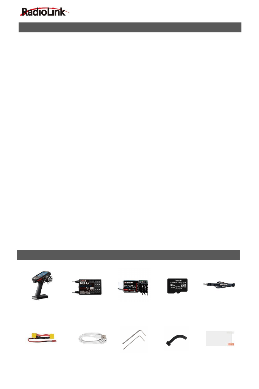
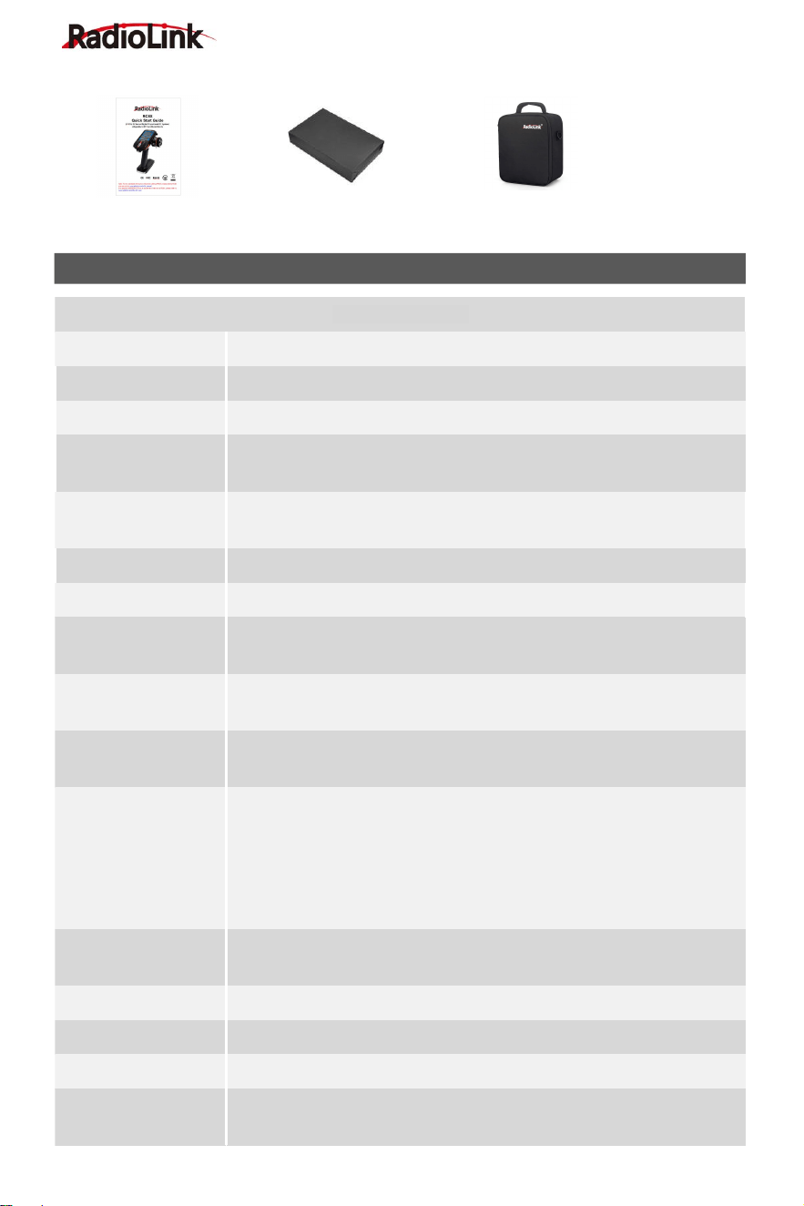
PACKING LIST
EXT Connect Cable×1 Type-C Cable×1 Hex Wrench×2 Spare Trigger×1 Screen Protector×1
RC8X Transmitter×1 R8FG Receiver×1 R4FGM Receiver×1 32G SD Card×1 Lanyard×1
(Installed in RC8X)
RadioLink Electronic Limited
www.radiolink.com
4
RC8X Transmitter
Dimension
L*W*H: 121*163*209mm (4.76"*6.42"*8.23")
Weight
438.5g (15.47oz)
Antenna Length
Built-in Antenna
Dimension of Battery
Case
L*W*H =92*52*14.5mm (3.62"*2.05"*0.57")
Applicable Model
Types
Car (Including Crawlers/Tanks/Caterpillars etc.)/Boat/Robot
Channels
8 channels
Screen
4.3 inches, 800*480 full-color, backlight IPS touch screen
Ground Control
Distance
600 meters(1968.5ft) (Maximum range tested in unobstructed areas
free of interference)
Operating Current
250mA±10mA@8.4V(the IPS screen light on);
190mA±10mA@8.4V(the IPS screen light off)
Operating Voltage
7
~
17V DC (8 pieces of AAA batteries or a 2S-4S LiPo battery or a 6S
Ni-MH battery);
Type-C Port
Voltage & Current
Output Voltage
:
5 V(RC8X can be powered by computer or mobile
power bank via Type-C cable)
Output Current
:
Maximum 500mA
Input Voltage
:
4.6V-5.0V
Input Current
:
Maximum 1A
DSC Port
Voltage & Current
Input Voltage: 0-5V;
Output Voltage: 0-3.3V
Frequencies Band
2.4GHz ISM band (2400MHz-2483.5MHz)
Modulation Mode
GFSK
Transmission Power
<20dbm
Spread Spectrum
Mode
FHSS, 67 channels pseudo random frequency hopping
SPECIFICATIONS
Quick Start Guide×1 Packing Box for Accessories×1 Carrying Bag×1
RadioLink Electronic Limited
www.radiolink.com
5
Channel Resolution
4096 with regular jitter of 0.5us
Response Latency
3ms, 4ms, 14ms can be selected
Alarm
Low transmitter voltage, low receiver voltage, low model battery
voltage, or low RSSI alarm can be customized
Model Memory
200 groups of model storage
ID Seed
16 groups
Compatible
Receiver
R8FG(Standard)/R8F/R8EF/R7FG/R6FG/R6F/R4FGM/R4F
Voice Broadcast
Support
CRSF Protocol
Support
FPV Head Track
Support
R8FG Receiver
Dimension
L*W*H =35*24*13.5mm (1.38"*0.94"*0.53")
Weight
10.5g (0.37oz)
Channel
8 channels
Antenna Length
205mm (8.07")
Control Distance
Ground 600 meters (1968.5ft) (Maximum range tested in
unobstructed areas free of interference)
Operating Current
35mA (5V)
Operating Voltage
3-12V
Signal Output
SBUS&PWM
Telemetry
Real-time built-in telemetry of model battery voltage, RSSI, and
receiver voltage
Gyro
Receiver with gyro integrated, customizable gyro sensitivity
Water Splash Proof
The waterproof grade is IPX4
Response Latency
3ms, 4ms, 14ms can be selected (If you want to select 3ms or 4ms
digital servo speed, make sure it is R8FG V2.1, or R8FG receiver with
a factory date of 2023/4/26 and later )
Compatible
Transmitter
RC8X/RC6GS V3/RC4GS V3/RC6GS V2/RC4GS V2/RC6GS
(3-position switch version)/RC4GS (version with P.D AFTER 180101)
/T8FB(BT)/T8FB(OTG)/T8S(BT)/T8S(OTG)
RadioLink Electronic Limited
www.radiolink.com
6
R4FGM Receiver
Dimension
25*13mm (0.98*0.51")
Weight
3g (0.11oz)
Channel
4 channels
Antenna Length
90mm (3.54")
Control Distance
400 meters on the ground
Operating Current
30mA@5V
Operating Voltage
3-6V
Signal Output
PWM
Gyro
Receiver with gyro integrated, customizable gyro sensitivity
Response Latency
3ms, 4ms, 14ms can be selected (If you want to select 3ms or 4ms
digital servo speed, make sure it is R4FGM V2.1, or R4FGM receiver
with a factory date of 2023/4/26 and later )
Compatible
Transmitter
RC8X/RC6GS V3/RC4GS V3/RC6GS V2/RC4GSV2/RC6GS/
RC4GS/T8FB(BT)/T8S(BT)/T8FB(OTG)/T8S(OTG)
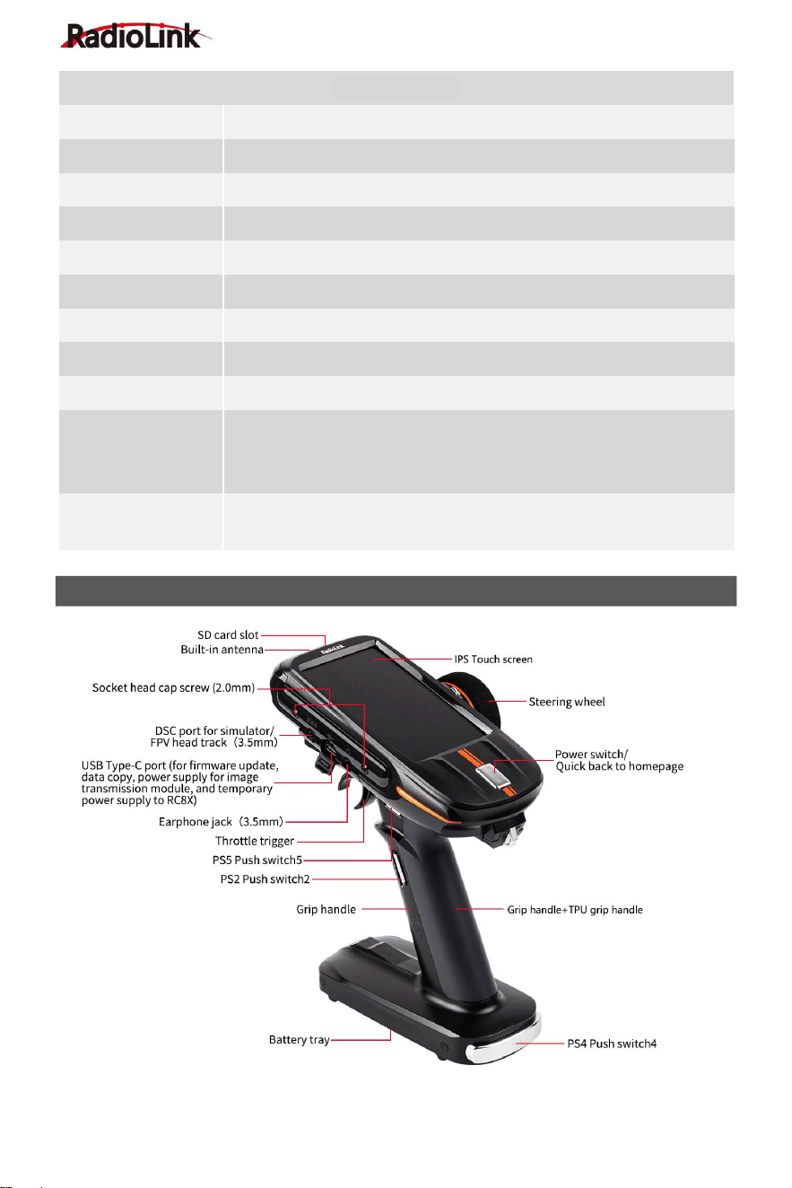
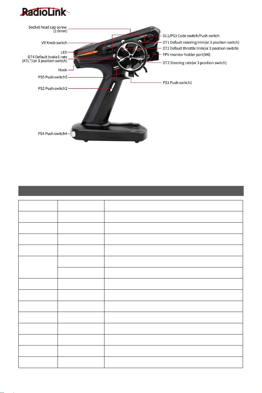
RC8X OVERVIEW
RadioLink Electronic Limited
www.radiolink.com
7
The USB Type-C port of RC8X can be used to update firmware, copy data, supply power to
image transmission module, and temporarily supply power to RC8X. You can connect the power
supply such as a computer to the Type-C port to supply 5V power to RC8X.
Note: 1. When the USB Type-C port is used to supply power to RC8X, please remove the battery
to avoid over-discharging. 2. The maximum input voltage of the RC8X Type-C port is 5V.
Switch/Knob
Full name
Function
DT1
Digital Trim 1
default steering trim
DT2
Digital Trim 2
default throttle trim
DT3
Digital Trim 3
Default ratio switch
DT4
Digital Trim 4
Default brake rate (brake1)
DL1/PS3
Digital Dial 1
Code switch, Gyro gain
Push Switch 3
Default to turn on/off backlight (can be customized)
PS1
Push Switch 1
Default control CH4, can be programmed
PS2
Push Switch 2
Default control CH5, can be programmed
PS4
Push Switch 4
Default control CH6, can be programmed
PS5
Push Switch 5
Default control CH7, can be programmed
VR
Knob switch
Dial, default control CH3, can be programmed
HOME
Power switch /Switch for quick back to homepage
SS
Steering switch
Default control CH1 to turn left and right
TS
Trigger switch
Default control CH2 go forward or backward
BUTTON INTRODUCTION
RadioLink Electronic Limited
www.radiolink.com
8
Three Position Switch
The four DT buttons can be used as four 3 position switches by setting. The setting method is as
follows:
1.Select any DT button for the channel to be set in the "Channel Setting" menu.
2.Enter "Trim/Dial select" menu, and set the step of the corresponding DT button to 100,
so that every time the DT button is toggled, the travel amount will go directly to 100. You can also
set different values according to your needs (Note: Trim step defaults to 2).
3.After setting, the DT button can be used as a 3-position switch. Return to the home
page and toggle the corresponding DT button to check the servo display.
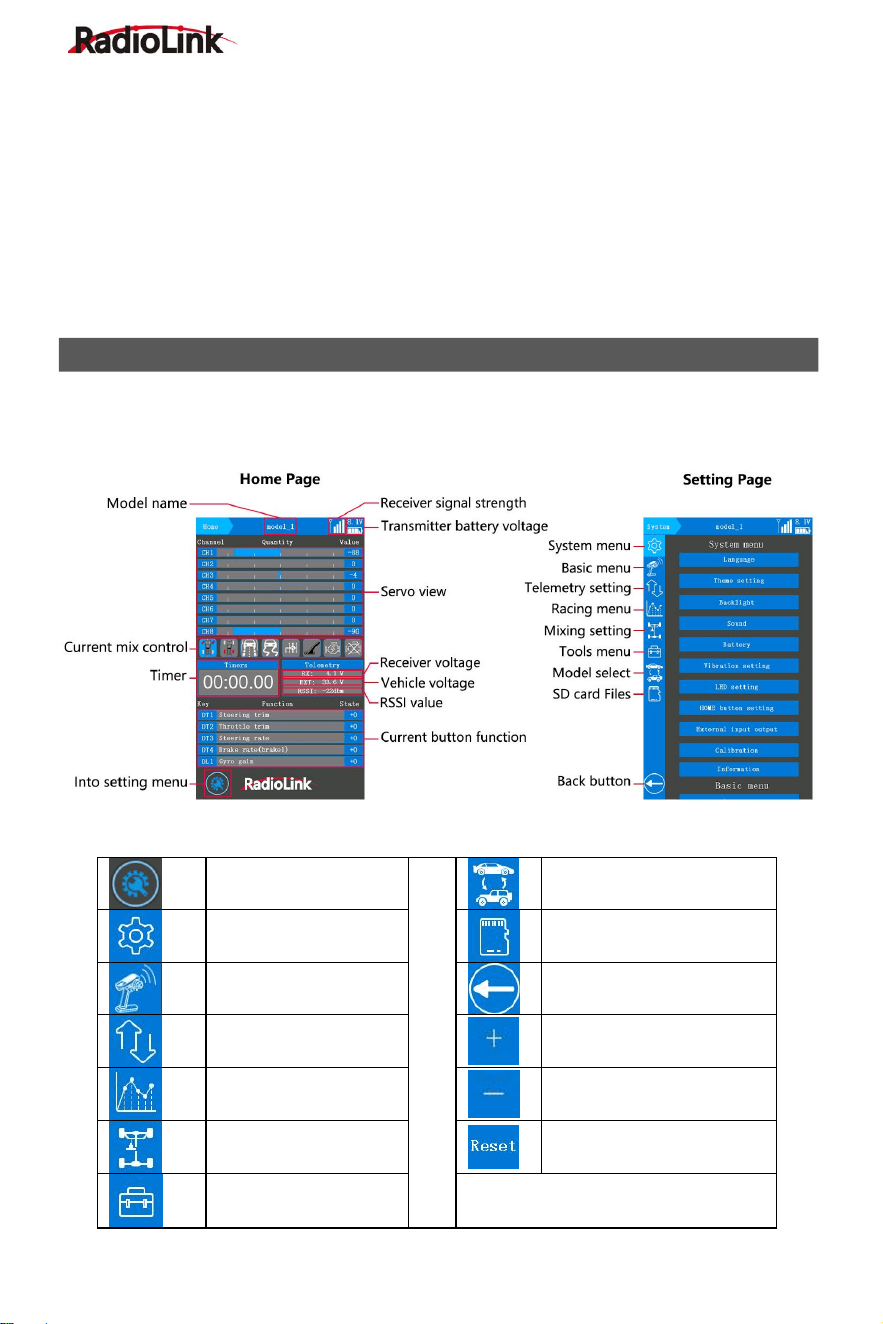
Power on RC8X
Long press the HOME button for about 1.5 seconds to power on RC8X. Click the icon in the
lower left corner of the home page to enter the setting page.
Icon introduction
Into setting menu
Model select menu
System menu
SD Card Folder
Basic menu
Back to previous menu
Telemetry setting
Increase the value
Racing menu
Decrease the value
Mixing setting
Reset the value
Tools menu
MENU INTRODUCTION
RadioLink Electronic Limited
www.radiolink.com
9
RC8X Basic Functions
System
menu
Language
Racing
menu
Steering delay
Theme setting
Throttle delay
Backlight
Cruise control
Sound
Idle up
Battery
Trigger setting (Trigger)
Vibration setting
Traction control
LED setting
A.B.S
HOME button setting
Motor Start
External input output
Engine cut
Calibration
Mixing
setting
Steering mixing
Information
Brake mixing
Basic
menu
Channel reverse
Gyro mixing
End point (EPA)
4WS mixing
Sub trim
Dual ESC mixing
Channel setting
CPS mixing
Channel limiter
Tank mixing
Trim/Dial select
Programmable mixing
Switch select
Tilt mixing
Double ratio
Tools
menu
Screenshot setting
Fail-safe
Timer
Receiver setting
Roll out chart
Telemetry
setting
Receiver signal
Gear ratio chart
Transmitter voltage
Model
select
menu
Model select
Receiver voltage
Copy model
Engine battery voltage
Paste model
Telemetry broadcast
Rename
Racing
menu
Steering curve
Reset
Throttle curve
Delete model
Brake curve
SD Card
Folder
SD Card Folder
Acceleration
RadioLink Electronic Limited
www.radiolink.com
10
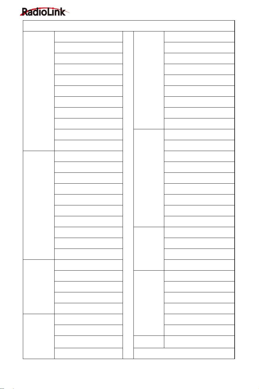
Transmitter Low Voltage Alarm
Transmitter low voltage alarm is 6.8V by default. If the voltage of
transmitter battery is lower than 6.8V, the transmitter will alarm with
sound "transmitter voltage low", please change the battery when
you heard the alarm, the transmitter low voltage alarm can be set
in the battery menu according to your battery that powered for your
RC8X.
Normally we set the alarm value with the single cell voltage as 3.7V.
If you use a 2S LiPo battery to power for your RC8X, you can set
the alarm to 7.4V for 2S LiPo battery (3.7V*2=7.4V), 11.1V for 3S
LiPo battery , and 14.8V for 4S LiPo battery.
Setting steps: turn on your RC8X, enter into System menu - Battery, and then adjust the alarm
voltage.
RC8X is packed with an 8-channel receiver R8FG, splash-proof, gyro integrated, and high
voltage servo supported. The gyro function of R8FG is turned off (Green LED) by default. Check
the follow gyro function introduction for methods on how to turn on the gyro.
Binding
RC8X and R8FG have finished binding by default. Turn on the RC8X and the R8FG, the signal
tower will show on the top of the screen as in the picture below, it means the transmitter and
receiver have finished binding.
Please make sure there is successful binding between the
transmitter and receiver. Each receiver has an individual ID
code. When the binding is done, the ID code will be stored in
the transmitter and there's no need to rebind.
Binding steps:
① Put the transmitter and the receiver close to each other (about 60 centimeters).
② Turn on both the transmitter and the receiver, and then the LED of R8FG will start flashing
slowly.
③ There is a black binding button (ID SET) on the side of the receiver. Press the button for more
than 1 second and release, the LED will flash quickly, indicating the binding process is ongoing.
④ When the LED stops flashing and is always on, binding is complete and there will be a signal
tower shown on top of the IPS screen of the transmitter(As shown above). If not successful, the
R8FG INTRODUCTION
RadioLink Electronic Limited
www.radiolink.com
11
LED will keep flashing slowly to notify, repeat the above steps.
Note: The close distance between the transmitter and receiver may cause a signal block, which
leads to unsuccessful binding or signal loss. After the binding is successful, if RC8X and R8FG
receiver are too close (for example, within 60 centimeters), the signal may also be lost because
of signal block. Bring RC8X transmitter and R8FG receiver farther apart, the signal loss will
disappear automatically.
Receiver Setting
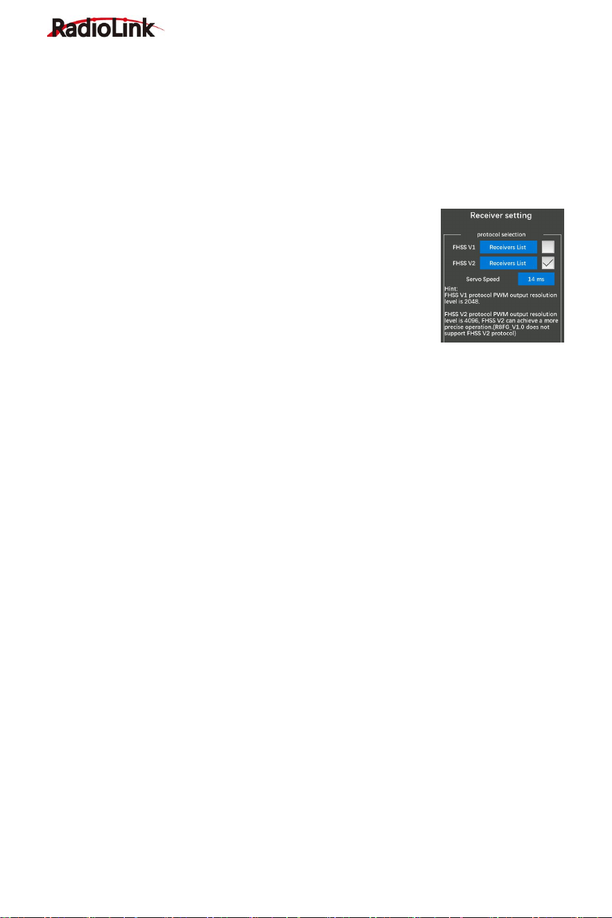
Receiver Selection (Protocol Selection):
If the receiver you are using is not the standard R8FG, but other
versions R8FG or other receivers such as R7FG, R6FG, etc., please
select "FHSS V1" or "FHSS V2" in the "Basic Menu" - "Receiver
setting" of RC8X (as shown on the right), and then bind them. FHSS
V1 receivers have a PWM output resolution of 2048, and FHSS V2
receivers have a PWM output resolution of 4096. The higher the
resolution, the more delicate the angle of servo motion.
Please click "Receivers List" (as shown above) to check whether the receiver you are currently
using belongs to this list. If yes, please click the box on the right to confirm the current receiver
type. If not, please do not select this list. If the receiver list selected here does not include the
receiver model you are actually using, the binding may not be successful. For example: If you
want to use R7FG with RC8X, you need to select FHSS V1 and then bind them. If FHSS V2 is
selected, binding will not be successful.
Servo Speed Setting:
1. Transmitter: It is necessary to update the RC8X firmware to V1.1.5 or above, and then select
FHSS V2 protocol to display this option. Servo speed can be selected from 14ms, 4ms, and 3ms.
The default servo speed is 14ms (analog servo speed), 4ms and 3ms (digital servo speed).
2. Receiver: If you are using a digital servo, you need to choose a servo speed of 4ms or 3ms.
Please confirm whether the receiver you are using supports digital servo. Currently, RadioLink
receivers that support digital servo include R8FG V2.1, R4FGM V2.1, and R8FG and R4FGM
receivers with a factory date of 2023/4/26 and later. Other versions of RadioLink receivers do not
support digital servo. Even if 4ms or 3ms is selected when using them, the default servo speed is
14ms. RadioLink will continue to add other models of receivers that support digital servos in the
future. Please pay attention to RadioLink official website.
3. Status indication: When switching the servo speed, the green LED light of the receiver will
flash twice, which means that the switching of the servo speed is successful; if the green LED of
the receiver does not flash when switching the servo speed of the servo, it means that the
switching of the servo speed of the servo is unsuccessful or the current receiver does not
support digital servos.
Attention:
1. RC8X comes with R8FG receiver. R8FG V1.0 (production date before Feb. 6, 2023) only
supports FHSS V1 protocol, not FHSS V2 protocol; R8FG V2.0 and later versions (production
date on or after Feb. 6, 2023) support FHSS V2 protocol. Mini receiver R4FGM V1.0 supports
FHSS V1 protocol, and R4FGM V2.0 and later versions support FHSS V2 protocol. Before
RadioLink Electronic Limited
www.radiolink.com
12
operating the model, please make sure protocol of the receiver is selected correctly, otherwise
some functions will not work properly.
2. The receivers that compatible with the RC8X is keep updating, please pay attention to
RadioLink official website www.radiolink.com to get the latest firmware to check the newly
launched receiver. This page is only to display the receiver models which are compatible with the
RC8X.
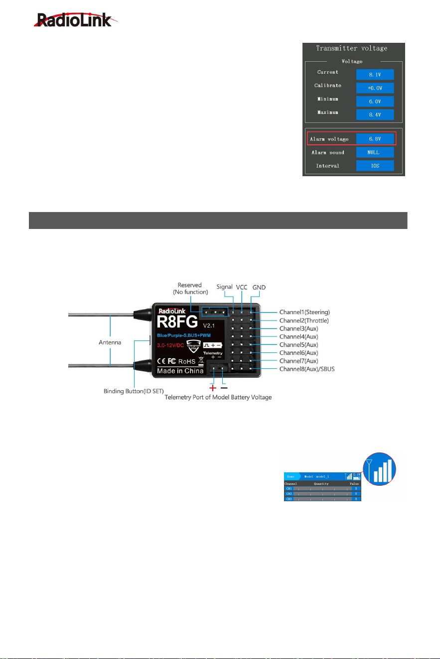
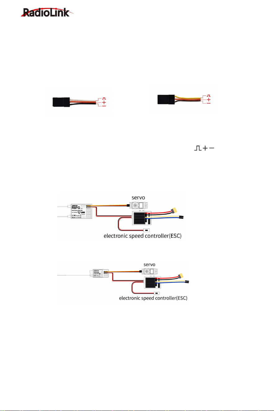
Receiver Connection
Picture 1 Picture 2
The connection wire for the receiver is shown in the picture above. The common ones are
white/red/black wire (Picture 1) or yellow/red/brown wire (Picture 2). The two types of servo
cables both are light-colored wire as the signal wire, and dark-colored wire as the ground wire,
and the middle is 5V power supply, and the three wires correspond to " ".
Note: RadioLink receivers are all designed with anti-polarity connect protection. When the
receiver is powered by a separate battery, the receiver will not be damaged if the battery polarity
is reversed, but if the servo is connected at this time, it will damage the servo.
The Connection of servo, ESC and receiver.
R8FG Receiver Connection (As above)
R4FGM Receiver Connection (As above)
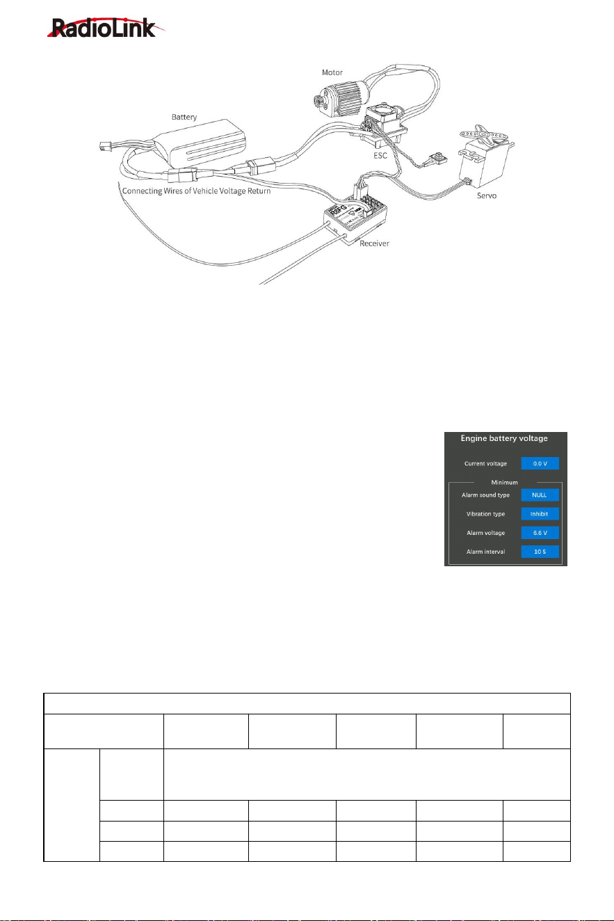
Telemetry of Model and Receiver Battery Voltage
R8FG supports telemetry of model battery voltage, receiver voltage, and RSSI. The model
voltage will display by connecting the wire to the ESC (Electronic Speed Control), battery, and
Telemetry port of receiver R8FG. Telemetry of maximum 8S (33.6V) battery supported. Model
battery voltage telemetry can be easily achieved by connecting the male end of the telemetry
wire to ESC while the female end to the battery and the wire with a JST head connects
Telemetry (+-) of R8FG as below picture shows. No extra module is needed. Once connect with
success, the returned model voltage will be displayed on the home page of the transmitter. The
connection is shown below.
RadioLink Electronic Limited
www.radiolink.com
13
Attention:
1. Reverse polarity protection circuit design for all 8 channels of R8FG ensures vital components
are protected from a reverse polarity connection. But, the JST connector which is packed with
R8FG for connecting to the battery cannot reverse polarity connect, or it will lead to the wrong
voltage value telemetry.
2. Telemetry port is only used to model voltage telemetry. It can not be used to power the
receiver.
Low Model Voltage Alarm Setting
The low model battery voltage alarm is default 6.6V, if the voltage of
the model battery is lower than 6.6V, the transmitter will alarm with the
sound "low engine battery voltage", please replace the battery when
you heard the alarm, the value of low engine battery voltage alarm can
be set in the Telemetry setting - Battery. Normally we set the warning
value with the single cell voltage as 3.7V. For example, if it is a 3S
lithium battery used in the model car, the warning value can be set as
11.1V (3.7V*3S).
Working Modes of R8FG
R8FG has a built-in gyroscope, which can output not only PWM signals but also SBUS signals.
There are four working modes, including ordinary PWM mode, SBUS mode, Gyro mode, and
Gyro + SBUS mode. The channel signal corresponding to each mode is as follows:
R8FG Working Modes
Working Mode
PWM Mode
SBUS Mode
Gyro mode
Gyro+SBUS
Mode
Note
Channel
Telemetry
Telemetry Port of Model Battery Voltage
(
+ -
)
TELEMETRY port is only for 2S-8S battery voltage telemetry. The port
cannot be used to power the receiver.
1
PWM
PWM
PWM
PWM
Steering
2
PWM
PWM
PWM
PWM
Throttle
3
PWM
PWM
PWM
PWM
Aux
RadioLink Electronic Limited
www.radiolink.com
14
4
PWM
PWM
PWM
PWM
Aux
5
PWM
PWM
PWM
PWM
Aux
6
PWM
PWM
PWM
PWM
Aux
7
PWM
PWM
PWM
PWM
Aux
8/S.BUS
PWM
S.BUS
PWM
S.BUS
Aux
Working mode setting
1.Turn on/off the gyro: Short press the binding button 3 times within 2 seconds to switch
the gyro on and off, and the color of the LED indicator will switch accordingly.
2.Gyro phase switch: Short press the binding button twice within 2 seconds to switch the
gyro phase.
3.Turning on/off the SBUS: short press the binding button once to turn on/off the SBUS,
and the color of the LED indicator will switch accordingly. After SBUS signal is enabled, channel
1-7 output PWM, and channel 8 outputs the SBUS signal.
LED Indicator Color in Different Working Modes
Working Mode
PWM Mode
Gyro mode
SBUS Mode
Gyro + SBUS Mode
Indicator Color
Green
Red
Blue
Red+Blue
Note: When the receiver is connected to the power supply, if there is no successful binding
between the receiver and the transmitter or the receiver loses the signal, the indicator of the
receiver will flash slowly.
Gyro Function of R8FG
R8FG has a built-in gyroscope. The integrated high-performance gyro adopts the software filter
and PID algorithm, timely and precisely corrects the sensitivity and improves the stability. Its
good flexibility to different models easily achieves professional performance even with drift cars.
Enable Gyro
The gyro function of R8FG is turned off by default. Since the integrated gyro in R8FG will
self-check, it is important to keep R8FG still when powering it on. Short press the binding button
3 times within 2 seconds to switch the gyro on and off, and the color of the LED indicator will
switch accordingly. Red LED indicates that gyro is enabled.
Attention: It's normal that the servo keeps shaking when connected to the receiver. Because the
gyro is helping to correct the steering gear angle of the servo automatically if the gyro function
has turned on, you can turn off the gyro function if you do not need this function.
If the receiver has not to be moved, but the servo keep shaking, there are two reasons below:
① The servo has connected to the S.BUS channel of the receiver. Please reconnect the servo to
the CH1/2/3/4/5/6/7, because the standard servo only supports PWM signal input.
② The gyro is too much sensitive. Please turn DL1 switch to reduce the gyro sensitivity.
RadioLink Electronic Limited
www.radiolink.com
15
Gyro Reverse
Set the gyro forward, and turn the car right or left to see whether the gyro functions. The wheel
will turn left when the car is turned right and the wheel turns right when the car is turned left. If the
gyro acts counter, press the binding button twice, the red LED flashes twice, the gyro reverse is
corrected.
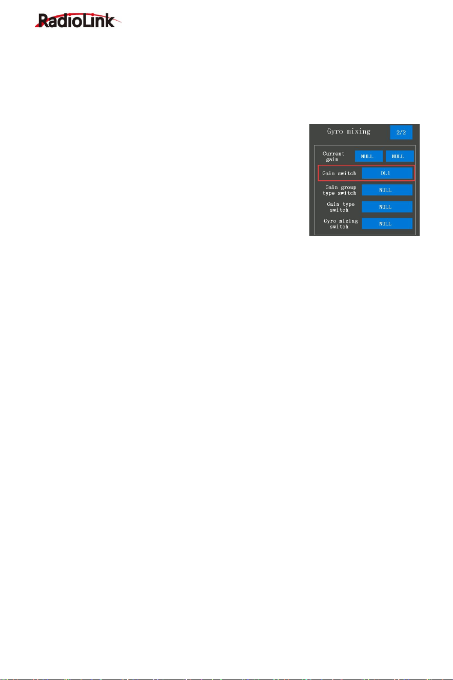
Gyro Sensitivity Setup
Gyro sensitivity is defaulted to adjust by channel eight that default
controlled by DL1/PS3 knob switch, turning the DL1/PS3 knob
switch clockwise to increase sensitivity and anti-clockwise to
reduce it. When turning the DL1/PS3 knob switch, a tooltip with
yellow background color will pop out at the top of the screen, and
the value of the channel will be changing at the same time, the
value is closer to +100, the higher sensitivity. If the value is 0, it
means the gyro function has been turned off.
You can also assign other switches to control the gyro function or adjust the sensitivity on this
page.
For more after-sales service:
Please send mail to: after_service@radiolink.com.cn
The detailed Electronic Instructions could be downloaded from RadioLink:
www.radiolink.com/rc8x_manual
Thank you again for choosing our product.