
Delta series, manufactured by MC2 Audio
DELTA 20
Operating Instructions
Dynaudio A/S
8660 Skanderborg, Denmark
www.dynaudio.com

Page 2

Page 3
CONTENTS
DECLARATION OF CONFORMITY ............................................................................ 4
THANKS ................................................................................................................... 5
INTRODUCTION ....................................................................................................... 5
IMPORTANT SAFETY INSTRUCTIONS .................................................................... 6
INSTRUCTIONS DE SECURITE IMPORTANTES ...................................................... 7
Installing Your Amplifier: Electrical Considerations ............................................. 8
Installing Your Amplifier: Mechanical Considerations .......................................... 9
Installing Your Amplifier: RF Emissions ............................................................... 9
About Your Amplifier: Dynamic Amplifier Performance Measurements ............ 10
Connecting To Your Amplifier: Line Inputs and Outputs ...................................... 11
Connecting To Your Amplifier: Speaker Outputs .................................................. 12
Connecting To Your Amplifier: Bridged (Mono) Operation ................................... 13
Operating Your Amplifier: Front Panel Controls and Indicators .......................... 14
Operating Your Amplifier: Rear Panel Sockets and Switches ............................. 15
Operating Your Amplifier: Initial Set-up and Switching On .................................. 16
Switching On… ........................................................................................................................... 16
Operating Your Amplifier: Switching between analogue & networked audio ..... 17
Operating Your Amplifier: General Purpose Connections (GPIO) Port ................ 18
Internal Adjustments to Your Amplifier: Fixed fan speed .................................... 19
Internal Adjustments to Your Amplifier: Auto-standby mode ............................ 20
Internal Adjustments To Your Amplifier: Changing the Gain ............................... 21
Looking After Your Amplifier: Maintenance ........................................................ 22
Looking After Your Amplifier: Warranty .............................................................. 22
Performance Of Your Amplifier: Specifications .................................................. 23
Performance Of Your Amplifier: Thermal Specifications.................................... 24
Appendix I: Speaker Backup Inputs ..................................................................... 25
Appendix II: 70/100V line output operation .......................................................... 26
Appendix III: 70/100V line distributed audio systems .......................................... 27
Introduction .............................................................................................................................. 27
How It Works ............................................................................................................................ 27
Example: How many speakers can I connect to an amp channel? .......................................... 28
Getting The Best Performance ................................................................................................. 29
In Conclusion… .......................................................................................................................... 31

Tel: +44 (0) 1404 44633 | Email: [email protected].uk | VAT: GB 589 4223 04 | EORI: GB589422304000 |
www.mc2-audio.co.uk | www.facebook.com/mc2audcio
DECLARATION OF CONFORMITY
We, the manufacturer:
XTA Electronics Ltd
(TRADING AS MC
2
Audio)
Units 6-7 Kingsgate
Heathpark Industrial Estate
Honiton, Devon
England
EX14 1YG
acknowledge our responsibility and self-certify the following products:
Kind of equipment: Audio amplifier
Commodity Code: 8518400090
Type Designation: I38/I68/I64
Delta40DSP, Delta80DSP, Delta100DSP
Delta20ND, Delta40ND, Delta80ND, Delta100ND, Delta120ND
DPA40, DPA80, DPA100
DNA20, DNA40, DNA80, DNA100, DNA120
T500, T1000, T2000, T4-250
Ti500, Ti1000, Ti1500, Ti2000, Ti3500, Ti4-250
E15, E25, E45, E475
S800, S1400
and all OEM/variants of these models
are manufactured in accordance with EMC Directive 2014/30/EU (CE and UKCA), in compliance with the following norm(s)
or document(s):
Technical Regulations: EN61000-3-2:2014 (Mains Harmonic)
EN61000-3-3:2013 (Mains Flicker)
EN55032:2015 (Emissions)
EN55032:2017 (Immunity)
and in accordance with the: Low Voltage Directive 2014/35/EU (CE and UKCA)
in compliance with the following norm(s) or document(s):
Technical Regulations: EN/IEC62368-1:2020 (Audio, Video & Communication Safety)
and in accordance with the Directive 2011/65/EU on the restricted use of certain Hazardous Substances in Electrical and
Electronic Equipment (RoHS2). We certify that the above-mentioned products are deemed compliant according to the
details given in the directive.
Signed: ……………………………………………………………………
Name: Alex Cooper
Position: Research and Development Manager
Date: Jan 2024

Page 5
THANKS
Thank you for choosing a Delta Series amplifier for your application.
Please spend a little time reading through this manual, so that you obtain the best possible
performance from the unit and become familiar with its operating requirements.
All MC
2
products are carefully designed and engineered for cutting-edge performance and
world-class reliability. If you would like further information about this or any other MC
2
product,
please contact us.
We wish you many years of service from this amplifier and look forward to hearing from you in
the near future.
INTRODUCTION
The Delta Series has been designed to combine incredible audio power and performance with
ultra-flexible connectivity for both remote control and audio. Exemplary audio processing is
assured through the use of XTA’s DSP platform in the DSP enabled models, and power amplifier
capabilities are taken care of with high efficiency output stages and a generous power supply.
Accepting analogue,
or optional Dante networked audio
, this extra connectivity means that the
Delta Series non-DSP models can also be used in installation systems which already have a
centralized DSP core but require the flexibility of being able to pick up multiple channels of
audio from a network.
With a range of power levels available in the Delta Series, the non-DSP amplifiers can be
networked to a single Delta DSP model, creating a powerful, efficient system that’s easy to
expand and adapt for use in live, install and everything in between.
#powermeetsprocessing
Page 6
IMPORTANT SAFETY INSTRUCTIONS
CAUTION: RISK OF ELECTRIC SHOCK.
DO NOT OPEN
WARNING: Apparatus with CLASS I construction shall be connected to a MAINS socket outlet with a protective earthing
connection.
WARNING: To prevent injury, this apparatus must be securely attached to the rack in accordance with the installation
instructions.
1. Read these instructions.
2. Keep these instructions.
3. Heed all warnings.
4. Follow all instructions.
5. Do not use this apparatus near water.
6. Clean only with a dry cloth.
7. Do not block any ventilation openings, install in
accordance with the manufacturer’s instructions.
8. Do not install near any heat sources, such as
radiators, heat registers, stoves or other apparatus
(including amplifiers) that produce heat.
9. Do not defeat the safety purpose of the polarized or
grounding-type plug. A polarized plug has two blades
with one wider than the other. A grounding-type plug
has two blades and a third grounding prong. The wide
blade or the third prong are provided for your safety. If
the provided plug does not fit into your outlet, consult
an electrician for replacement of the obsolete outlet.
10. Protect the power cord from being walked on or
pinched particularly at plugs, convenience
receptacles and the point where they exit from the
apparatus.
11. Only use attachments/accessories specified by the
manufacturer.
12. Use only with the cart, tripod, bracket or
table specified by the manufacturer, or sold with the
apparatus. When a cart is used, use caution when
moving the cart/apparatus combination to avoid injury
from a tip over.
13. Unplug t
his apparatus during lightning storms or
when unused for a long period of time.
14. Refer all servicing to qualified service personnel.
Servicing is required when the apparatus has been
damaged in any way, such as if the power-supply cord or
plug is damaged, liquid has been spilled or objects have
fallen into the apparatus, the apparatus has been
exposed to rain or moisture, does not operate normally,
or has been dropped.
15. Do not expose this equipment to dripping or
splashing and ensure that no objects filled with liquids,
such as vases, are placed on the equipment.
16. To completely disconnect this equipment from the
AC mains, disconnect the power cord from the mains
circuit breaker.
17. This unit is fitted with a 3-wire power cord. For
safety reasons, THE EARTH LEAD SHOULD NOT BE
DISCONNECTED IN ANY CIRCUMSTANCE.
18. Correct disposal of this product: This symbol
indicates that this product must not be disposed of with
household waste, according to the WEEE Directive
(2012/19/EU) and your national law. This product should
be taken to a collection center licensed for the recycling
of waste electrical and electronic equipment (EEE). The
mishandling of this type of waste could have a possible
negative impact on the environment and human health
due to potentially hazardous substances that are
generally associated with EEE. At the same time, your
cooperation in the correct disposal of this product will
contribute to the efficient use of natural resources. For
more information about where you can take your waste
equipment for recycling, please contact your local city
office, or your household waste collection service.
The lightning flash with arrowhead
symbol within an equilateral triangle
is intended to alert the user to the
presence 0f uninsulated “dangerous
voltage” within the product’s
enclosure that may be of sufficient
magnitude to constitute a risk of
electric shock to persons.
The exclamation mark within an
equilateral triangle is intended to
alert the user of important operating
and maintenance (servicing)
instructions in the literature
accompanying the appliance.
Page 7
INSTRUCTIONS DE SECURITE IMPORTANTES
ATTENTION: RISQUE DE CHOC ELECTRIQUE.
NE PAS OUVRIR
ATTENTION: Appareils de construction de CLASSE I doit être raccordé au réseau électrique via une prise de courant
reliée à la terre.
ATTENTION: Pour éviter toute blessure, cet appareil doit être solidement fixé à la torture, conformément aux
instructions d'installation.
1.
Lisez ces consignes.
2. Conservez ces consignes.
3. Respectez tous les avertissements.
4. Respectez toutes les consignes d’utilisation.
5. N’utilisez jamais l’appareil à proximité d’un liquide.
6. Nettoyez l’appareil avec un chiff on sec.
7. Veillez à ne pas empêcher la bonne ventilation de
l’appareil via ses ouïes de ventilation. Respectez les
consignes du fabricant concernant l’installation de
l’appareil.
8. Ne placez pas l’appareil à proximité d’une source de
chaleur telle qu’un chauff age, une cuisinière ou tout
appareil dégageant de la chaleur (y compris un ampli de
puissance).
9. Ne supprimez jamais la sécurité des prises bipolaires
ou des prises terre. Les prises bipolaires possèdent deux
contacts de largeur diff érente. Le plus large est le contact
de sécurité. Les prises terre possèdent deux contacts plus
une mise à la terre servant de sécurité. Si la prise du bloc
d’alimentation ou du cordon d’ali-mentation fourni ne
correspond pas à celles de votre installation électrique,
faites appel à un électricien pour eff ectuer le changement
de prise.
10. Installez le cordon d’alimentation de telle façon que
personne ne puisse marcher dessus et qu’il soit protégé
d’arêtes coupantes. Assurez-vous que le cordon
d’alimentation est suffisamment protégé, notamment au
niveau de sa prise électrique et de l’endroit où il est relié à
l’appareil; cela est également valable pour une éventuelle
rallonge électrique.
11. Utilisez exclusivement des accessoires et des appareils
supplémentaires recommandés par le fabricant.
12. Utilisez exclusivement des chariots, des
diables, des présentoirs, des pieds et des surfaces de
travail recommandés par le fabricant ou livrés avec le
produit. Déplacez précautionneusement tout chariot ou
diable chargé pour éviter d’éventuelles blessures en cas
de chute.
13.
Débranchez l’appareil de la tension secteur en cas
d’orage ou si l’appareil reste inutilisé pendant une longue
période de temps.
14. Les travaux d’entretien de l’appareil doivent être eff
ectués uniquement par du personnel qualifié. Aucun
entretien n’est nécessaire sauf si l’appareil est endommagé
de quelque façon que ce soit (dommages sur le cordon
d’alimentation ou la prise par exemple), si un liquide ou un
objet a pénétré à l’intérieur du châssis, si l’appareil a été
exposé à la pluie ou à l’humidité, s’il ne fonctionne pas
correctement ou à la suite d’une chute.
15. N'exposez pas cet équipement au fait de tomber goutte à
goutte ou au fait d'éclabousser et garantissez qu'aucun objet
rempli des liquides, comme les vases, n'est placé sur
l'équipement.
16. Pour complètement débrancher cet équipement de la
conduite principale de courant alternatif, débranchez la
corde de pouvoir du disjoncteur de conduite principale.
17. Cette unité est correspondue avec une corde de pouvoir
de 3 fils. Pour les raisons de sécurité, L'AVANCE DE TERRE
NE DEVRAIT ÊTRE DÉBRANCHÉE DANS AUCUNE
CIRCONSTANCE.
18. Mise au rebut appropriée de ce produit: Ce symbole
indique qu’en accord avec la directive DEEE (2012/19/EU) et
les lois en vigueur dans votre pays, ce produit ne doit pas
être jeté avec les déchets ménagers. Ce produit doit être
déposé dans un point de collecte agréé pour le recyclage des
déchets d’équipements électriques et électroniques (EEE).
Une mauvaise manipulation de ce type de déchets pourrait
avoir un impact négatif sur l’environnement et la santé à
cause des substances potentiellement dangereuses
généralement associées à ces équipements. n même temps,
votre coopération dans la mise au rebut de ce produit
contribuera à l’utilisation efficace des ressources
naturelles. Pour plus d’informations sur ’endroit où vous
pouvez déposer vos déchets d’équipements pour le
recyclage, veuillez contacter votre mairie ou votre centre
local de collecte des déchets.
Le symbole représentant un éclair fléché
dans un triangle équilatéral a pour but
d’alerter l’utilisateur de la présence
d’une “tension dangeruese” non isolée à
l’intérieur du boitier, pouvant être d’une
force suffisante pour constituer un
risqué d’électrocution.
Le point d’exclamation dans un triangle
équilatéral a pour but d’alerter
l’untilisateur de la présence d’instructions
importantes concernant le fonctionnement
et la maintenance, dans la documentation
qui accompagne l’appariel.

Page 8
Installing Your Amplifier: Electrical Considerations
The amplifier has been manufactured to comply with your local power supply requirements, but
before connecting the unit to the supply, ensure that the voltage (printed on the rear panel) is
correct.
The amplifier is fitted with a universal power supply that operates from 90V – 260VAC.
Make sure power outlets conform to the power requirements listed on the back of the unit.
Damage caused by connecting to improper AC voltage is not covered by the warranty.
SAFETY WARNING
Where a MAINS plug or appliance coupler is used as the disconnect device, it should remain
readily operable.
Where the amplifier is mounted in a rack and permanently connected to the mains, then the
rack should be installed with a readily accessible connector or an ALL POLE circuit breaker with
3mm breaking distances.
For use by professionals only.
For safety reasons,
THE EARTH LEAD SHOULD NOT BE DISCONNECTED IN ANY CIRCUMSTANCE.
If ground loops are encountered consult the section on connecting your amplifier on page 11.
The wiring colours are:
230V AREAS: EARTH = GREEN AND YELLOW
NEUTRAL = BLUE
LIVE = BROWN
DO NOT USE THE UNIT IF THE ELECTRICAL POWER CORD IS FRAYED OR BROKEN. The power
supply cords should be routed so that they are not likely to be walked on or pinched by items
placed upon or against them, paying particular attention to cords and plugs and the point where
they exit from the appliance.
ALWAYS OPERATE THE UNIT WITH THE AC GROUND WIRE CONNECTED TO THE ELECTRICAL
SYSTEM GROUND. Precautions should be taken so that the means of grounding of a piece of
equipment is not defeated.
DO NOT REMOVE THE LID. Removing the lid will expose you to potentially dangerous voltages.
There are no user serviceable parts inside.
ESD strikes to the unit’s front panel that are in excess of 4000 volts may cause disturbance to
the status LEDs on the unit. This will not affect audio performance and will be corrected on the
next power up cycle.

Page 9
Installing Your Amplifier: Mechanical Considerations
To ensure that this equipment performs to specification, it should be mounted in a suitable rack
or enclosure as described below. Like all high power amplifiers, it should be kept away from
other equipment which is sensitive to magnetic fields. Also, this amplifier may suffer a
substantial reduction in performance if it is subjected to, or mounted close to equipment which
radiates high radio frequency (RF) fields.
Warning: To prevent injury, this apparatus must be securely attached to the rack in accordance
with the installation instructions.
When mounting the amplifier in a rack or enclosure, be aware that…
THE FRONT PANEL IS NOT CAPABLE OF SUPPORTING THE UNIT ON ITS OWN.
Make sure that the rear of the unit is adequately supported. Rear bracket support holes are built
into the chassis. Brackets are available as an option.
ENSURE THERE IS ADEQUATE VENTILATION.
The cooling fans suck cool air in through the front and blow hot air out at the rear of the unit
through the ventilating grills. The front and rear of the amplifier should have free exposure to
the air (i.e. in a rack leave the front & rear doors off), with 2cm air gap at the sides.
IF AIR IS NOT ALLOWED TO ESCAPE FROM THE REAR, OVER-HEATING WILL OCCUR.
Take care when mounting other equipment in the same rack.
Make sure that the rack unit has a separate earth connection (technical earth).
Please also see the notes regarding maintenance on page 17.
Installing Your Amplifier: RF Emissions
The high frequency resonant converters in the Delta Series amplifiers have been designed to
have very low RF emissions; however, even these low-level emissions can cause interference
with other equipment.
In order for this to be minimised, the amplifier should be mounted in a metal rack enclosure,
which should have a separate (technical) Earth. Alternatively, a separate earth should be
attached to the amplifier using the rear panel earth point (see page 15).

Page 10
About Your Amplifier: Dynamic Amplifier Performance Measurements
The Delta Series are the very latest example of a ‘dynamic amplifier’. This new ‘breed’ of power
amplifiers provide very high peak power levels in a much smaller, and lighter, package than
previously possible with conventional amplifiers.
They are designed specifically for today’s high power audio installations, which use multiple
speakers with electronic crossovers or speaker controllers. These systems can handle very high
transient signals that far exceed their RMS power rating. The Delta Series amplifiers have been
designed to match this requirement and can deliver huge levels of power for short durations.
In order to protect themselves and the loudspeakers that they are driving, continuous signals
such as sine waves, are automatically detected and reduced (ramped down) to a safe level.
When trying to measure the power output however, continuous signals will give totally incorrect
results. A dynamic signal, such as a tone burst, should be used and the levels measured by
monitoring the waveform on an oscilloscope. The power envelope can then be accurately
measured.
Our power output figures are measured using signals with known Crest Factors and are quoted
at the rear of this manual on page 23 and on our website.
Please refer to the technical area of our website for further information – here you can
download a set of Crest Factor tailored audio samples to allow you to compare our specifications
with any other amplifier.

Page 11
Connecting To Your Amplifier: Line Inputs and Outputs
The inputs are made via 3-pin XLR connectors, which are electronically balanced and should be
connected via a high grade twin core screened cable, as follows:
PIN1: Screen (see note below)
PIN2: Hot (signal +)
PIN3: Cold (signal -)
The amplifier is designed to operate with fully balanced equipment and ground loops or loss of
performance may be experienced if connected to unbalanced sources. If it is unavoidable
however, the following wiring should be used. The cable should still be twin core plus screen.
PIN1: Screen - connected to the chassis of the unbalanced equipment - or left disconnected at
the unbalanced end.
PIN2: Hot (signal +)
PIN3: Cold (ground 0V)
NOTE: This amplifier is wired to the latest industry recommendations. PIN1 is connected
directly to the chassis/mains earth. If ground loops (mains hum) are encountered remove the
screen connection from the other end of the cable and leave it open circuit. If problems persist,
consult your dealer/supplier.
DO NOT TAMPER WITH OR ALTER ANY GROUND (EARTH) CONNECTIONS INSIDE THE
AMPLIFIER.
For bridged operation input should be made to channel A (or C) only and the channels set for
bridged mode for the appropriate pair of channels. Please see page 13 for details of how to do
this.
Page 12
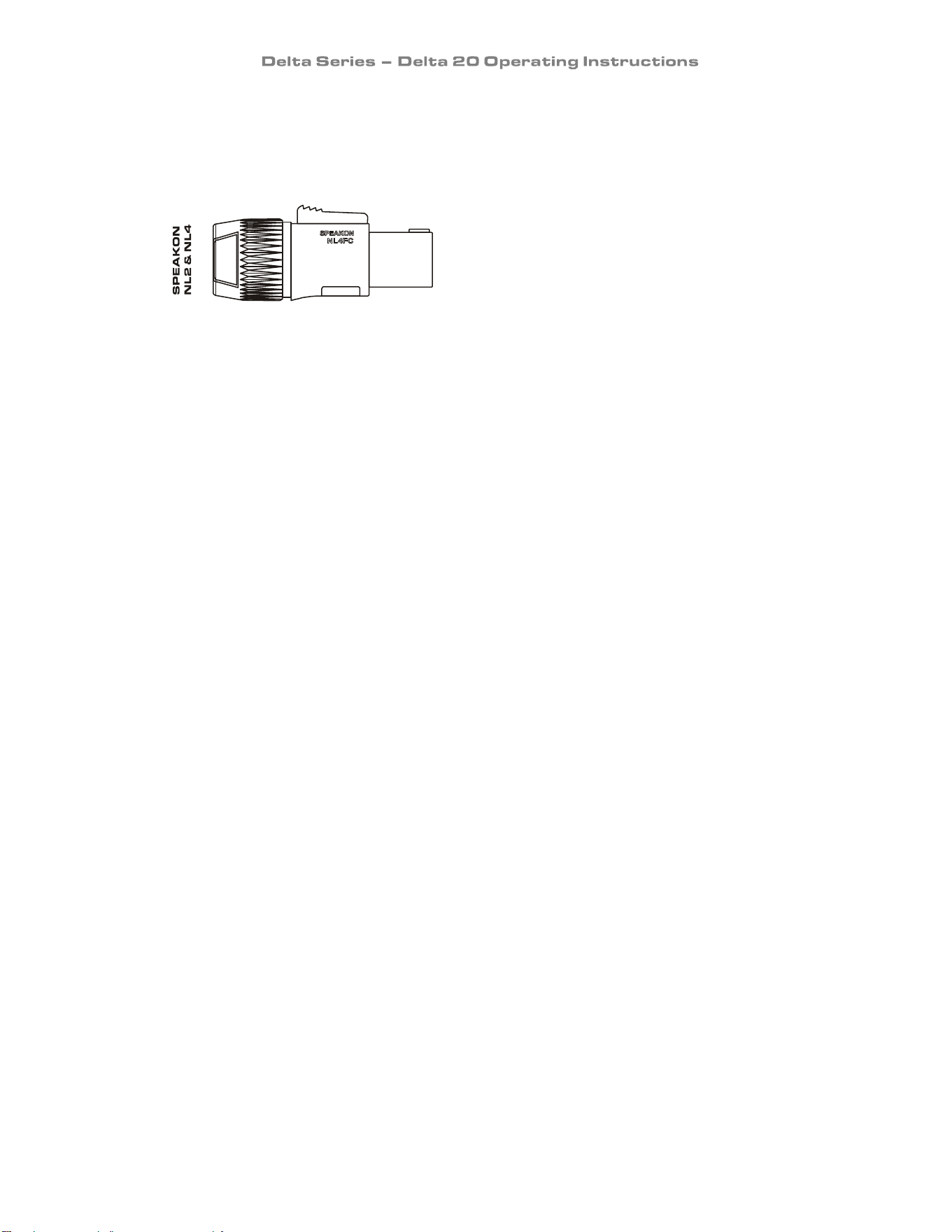
Connecting To Your Amplifier: Speaker Outputs
The speaker outputs are via Neutrik Speakon connectors. 2 pole (NL2FC) or 4 pole (NL4FC)
connectors can be used.
Pin 1+: Hot
Pin 1-: Cold
Additionally, Channel 1 Speakon connector carries Channel B2output on Pins +2 & -2 to allow
easy bi-amping or bridged operation using a single NL4 connector. Similarly, Channel 3’s
Speakon connector also carries Channel 4 output.
Output Connector 1
Pin 2+: Hot Ch. 2
Pin 2-: Cold Ch. 2
Output Connector 3
Pin 2+: Hot Ch. 4
Pin 2-: Cold Ch. 4
For bi-amped operation, connect as above.
As the currents involved are relatively high, and to ensure best performance, the speaker cables
should be kept as short as possible and conform to the following minimum requirements:
Delta 20 NON-DSP, 6A into 4 Ohm speaker loads
When operating the amplifier into loads of less than 4 Ohms, be aware that the current capacity
of the speaker cables will need to be increased above the values quoted here.
Do not connect the inputs/outputs to any other voltage source such as a battery, mains source or
power supply, regardless of whether the amplifier is turned on or off.
Do not run the output of any amplifier channel back into another channel’s input and do not
parallel or series-connect an amplifier output with any other amplifier output.

Page 13
Connecting To Your Amplifier: Bridged (Mono) Operation
Pairs of channels may be independently bridged – channel pair 1+2, and/or channel pair 3+4.
The method is the same for both channel pairs:
Select the required bridged mode using the rear panel switches (see page 15 for more
information).
Use Channel 1 or 3’s Output Speakon connector and connect as follows:
Pin 2+: Hot
Pin 1-: Cold
When operating in bridged mode, the minimum impedances are doubled.
The minimum load in bridged mode is 4 ohms.
Page 14
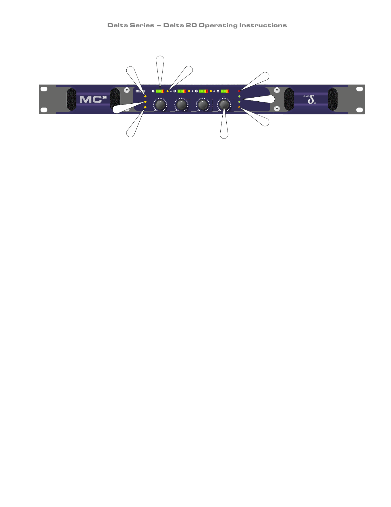
Operating Your Amplifier: Front Panel Controls and Indicators
1: POWER LED: This will illuminate when mains power is connected – there is no on/off switch
on this model.
2: ANALOGUE LED: This will illuminate when the selected source is the four input XLRs.
3: NETWORK AUDIO LED: This will illuminate when the selected source is the network audio
connection. To switch modes, use the rear panel switch as explained further on page 17.
4: Signal meters: These will show the level of the respective amplifier’s output channel. The
red LED in the meter will illuminate when the limiter threshold has been reached and limiting is
occurring.
5: LINK LEDs: This indicates if the channel is linked to its immediate neighbour. The link
switches are on the rear panel – see page 15 for details. Linking is disabled in Network Audio
mode and Link LEDs will be extinguished. The front panel attenuators will still operate
independently when channels are input linked.
6: PROTECTION LED: If a condition exists, that could cause damage to either the amplifier or
the speakers, the protection circuit will disengage the outputs and this LED will illuminate/flash.
This signal is also connected to a GPO pin on the rear panel for external monitoring – see page
18 for more information. Temperature related faults will reset automatically if the unit has
cooled sufficiently.
7: BRIDGE pair LEDs: The channel pair LED will illuminate if these channels have been
switched into bridged (mono) mode. If this is illuminated, the attenuation control of the even
numbered channel (so 2 or 4) will not function as both channels are being fed from the left hand
channel. See page 13 for details of how to connect your speaker to a bridged channel pair, and
page 15 for how to enable bridge mode.
8: STANDBY LED: The power amplifiers in the Delta 20 can be powered down leaving just the
input circuitry and Dante network audio card (if fitted) active. This LED illuminates when the
power amplifier sections are turned OFF.
9: Analogue level controls: These function in both analogue input and network audio input
mode. To switch modes, use the rear panel switch as explained further on page 17.
POWER
ANALOGUE
NET. AUDIO
PROTECTION
BRIDGE 1+2
BRIDGE 3+4
STANDBY
-12
-2 0
-2
0dB
-12
-2 0
-2
0dB
-1 2
-2 0
-2
0dB
-1 2
- 20
-2
0dB
LIM36121824 LIM36121824 LIM36121824 LIM36121824LINK LINK LINK
-4 -4 -4 - 4
-6 - 6 -6
NETWORK
AUDIO POW ER
AMPLIFIER
4
5
6
3
7
8
9
2
1
Page 15
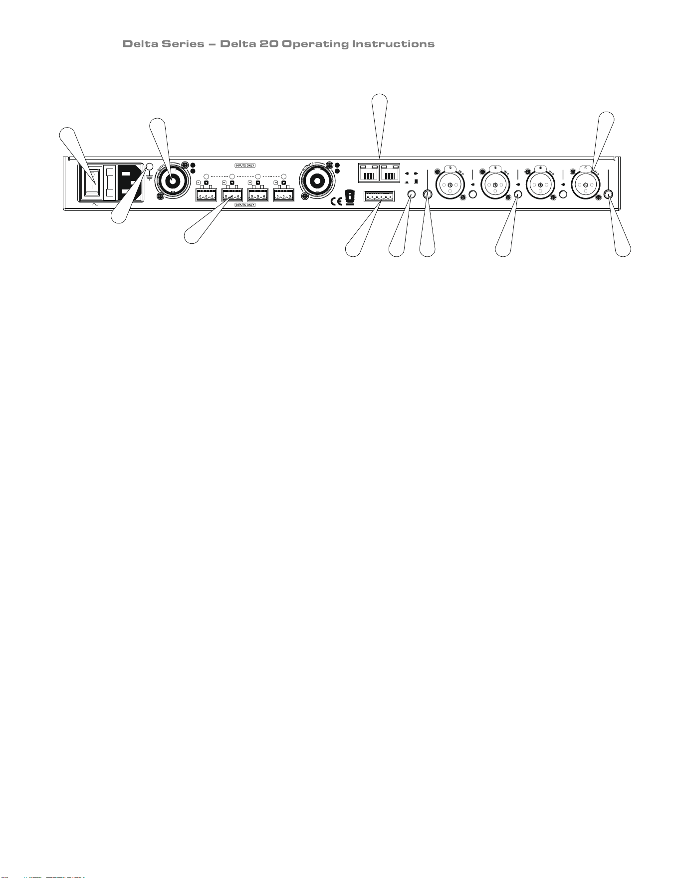
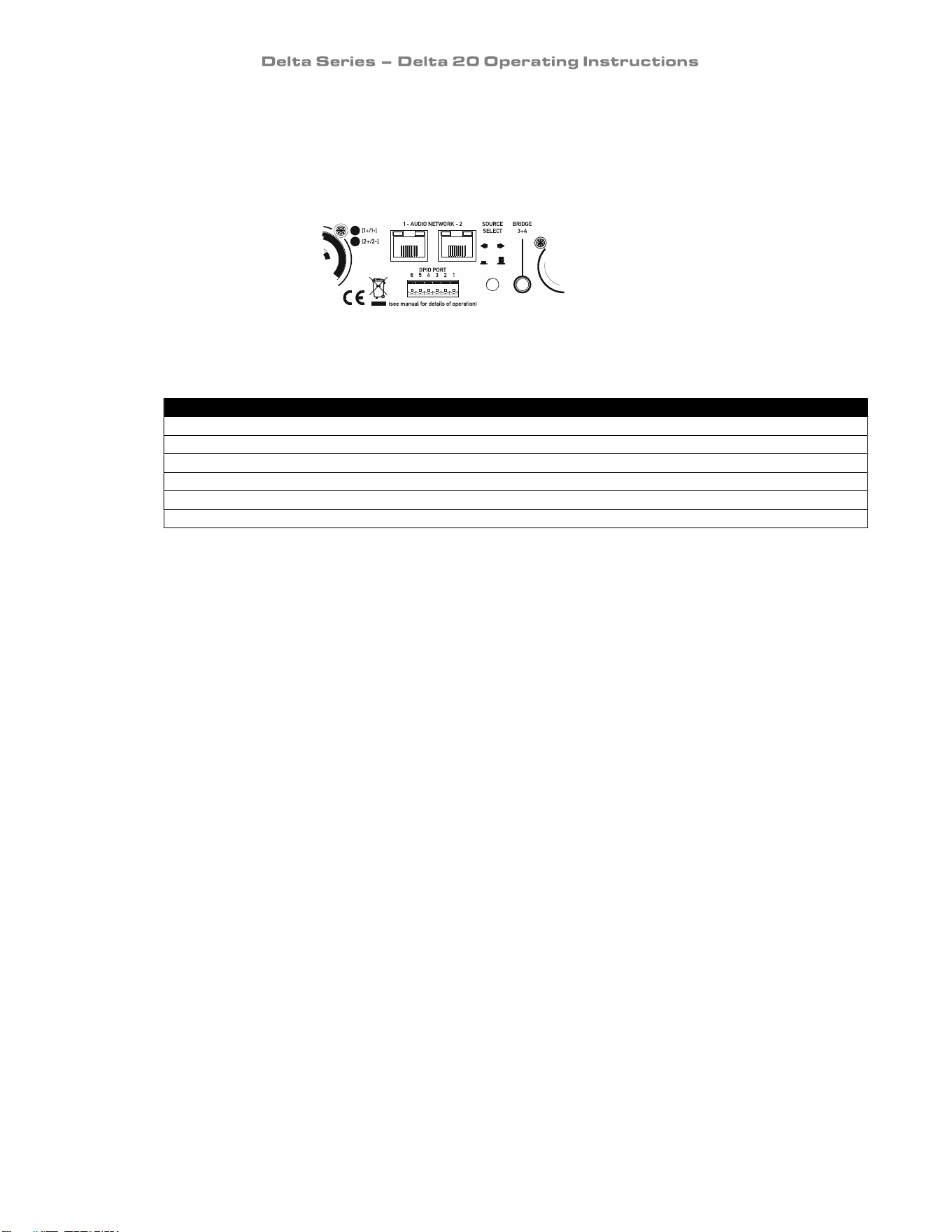
Operating Your Amplifier: Rear Panel Sockets and Switches
1: Mains input: IEC 3 pin (may not be switched on some versions – fuse is then internal)
2: Channel output Speakon socket: Output 1 is on pins 1+ hot, 1- cold. Channel 2’s output is also
wired to this socket to enable a single NL4 to provide both channels and to facilitate easier
wiring in bridged mode. Channel 3’s is wired pins 1+ hot, 1- cold. Similarly channel 4’s output
Speakon socket carries Channel 4’s output wired pins 2+ hot, 2- cold. Check the legend on the
rear panel for details.
3: Audio network connections: Four additional inputs can be added to the available input
choices via the optional Dante network card.
4: Input XLR sockets: Connect signal inputs to these sockets, wired pin 2 hot, 3 cold, 1 ground.
For sensitivity and impedance of these inputs, see the specifications on page 23.
5/7: Bridged (mono) switch (1+2)/(3+4): Press this switch to run this pair of amplifier channels
in bridged mode. To run 1+2 bridged, press the switch on the far left of the panel, beside
channel A’s input XLR.
6: Link switches: Press this switch to link the input of the channel to its immediate left.
Multiple channels may be linked using these switches so, for example, to link all outputs to input
A, press all three switches IN and use input A only. The front panel attenuators will still operate
independently when channels are input linked. Linking is disabled in Network Audio mode and
Link LEDs will be extinguished.
7: See 5/7 above.
8: Source select switch: This selects either the four analogue input XLRs or the output of the
network audio card as the audio source. It operates globally across all four channels. See page
17 for more information.
9: GPIO connections: 6 way mini-Phoenix connector. The amplifier reports back its status and
can be placed into standby using these connections. See page 18 for more information.
10: Speaker Backup Inputs: These sockets can be used to connect a backup amplifier that will
automatically be switched in circuit should the main amplifier lose power, or go into “Protect”.
See Appendix I on page 25 for further information on how to use this feature.
11: Technical Earth Point: Minimise interference by earthing directly to this connection. See
page 9 for information on RF emissions.
1 2 3 4 5 6
90V-240V AC 50-60Hz
BRIDGE
3+4
INPUT
LINK
BRIDGE
1+2
NC
1 - AUDIO NETWORK - 2MAINS SUPPLY
GPIO PORT
SOURCE
SELECT
INPUT
LINK
INPUT
LINK
DESIGNED AND MANUFACTURED IN ENGLAND by XTA Electronics Ltd. and MC Audio
2
[2+/2-]
[1+/1-]
[2+/2-]
[1+/1-]
(see manual for details of operation)
4 123
NC NC NC
SPEAKER BACKUP
(see manual for details of operation)
11
10
4
5
1
2
6
3
789

Page 16
Operating Your Amplifier: Initial Set-up and Switching On
Please read all documentation before operating your amplifier and retain all documentation for
future reference.
Do not spill water or other liquids into or on the unit and do not operate your amplifier while
standing in liquid.
Do not block fan intake or rear ventilation outlets or operate the unit in an environment that
could impede the free flow of air around the unit.
If your amplifier is used in an extremely dusty or smoky environment, it should be cleaned of any
collected debris at regular intervals. Please also see the notes regarding maintenance on page
17.
It is important that the power output of your amplifier is matched to the power handling capacity
of your loudspeaker. If not, damage to the loudspeaker could occur.
Switching On…
At ‘switch-on’ the protection circuit will initially activate whilst the circuits stabilise, indicated by
the red Protection LED illuminating, in addition to various other LEDs. After a few seconds the
red Protection LED will extinguish indicating a satisfactory working condition.
Other LEDs may remain illuminated depending upon rear panel switch settings and input
connections. If the Protection LED does not extinguish after 5 seconds the unit may be faulty or
some external connections may be incorrect or inappropriate. If this occurs, you should power
down the unit and remove all external connections (except for the mains power supply) and
repeat the power up sequence. If the problem persists please contact us – details on page 22.
Page 17
Operating Your Amplifier: Switching between analogue & networked audio
Your amplifier may be fitted with a Dante network audio card, which includes 24-bit 96kHz high
performance analogue to digital converters, allowing the amplifier to use four channels chosen
from a Dante network.
As the digital audio network will most likely be running at a higher level compared to your
analogue inputs, we strongly recommend you turn the front panel attenuators to minimum
before switching modes.
To switch to network audio mode, depress the rear panel switch marked “Source Select”.
Slowly increase the levels again after the mode has been changed.
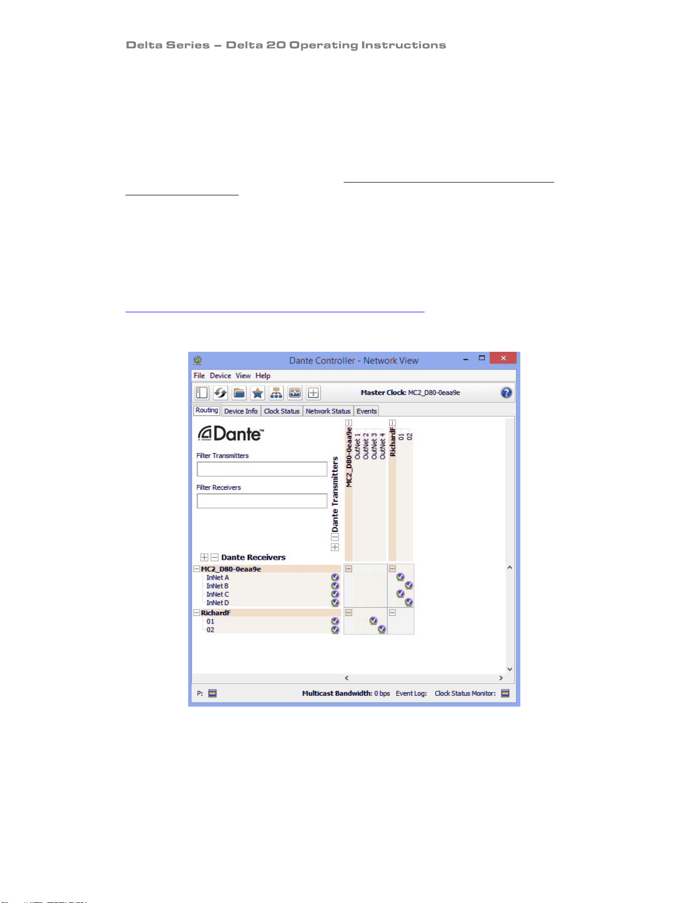
You will need to use Dante Controller to choose which channels to feed to the amplifier’s inputs.
It can be downloaded free here:
https://www.audinate.com/products/software/dante-controller
The amplifier’s inputs will appear in a manner similar to the example below:
Note that the rear panel “Link” switches do not function in Network Audio mode as any linkage
can be set up as part of the source selection within Dante Controller. Front panel “Link” LEDs
will also extinguish.
Page 18
Operating Your Amplifier: General Purpose Connections (GPIO) Port
The 6-way mini-Phoenix connector on the rear panel of the Delta 20 allows the amplifier to
report back to building management systems on its operating state and permits the amplifier to
be remotely switched in and out of standby.
The pins are configured as described in the table:
Port Pin # Pin Description
1
Chassis ground
2
Electrical ground (0V)
3
Standby input – short to 0V to put amplifier in standby
4
Power on – active high - +5V denotes amplifier is ON (but may be in standby)
5
Standby output – active high – +5V denotes amplifier is in standby (auto/remote/Dante)
6
Protect
–
active
low
–
0V denotes
amplifier is in PROTECT
Page 19
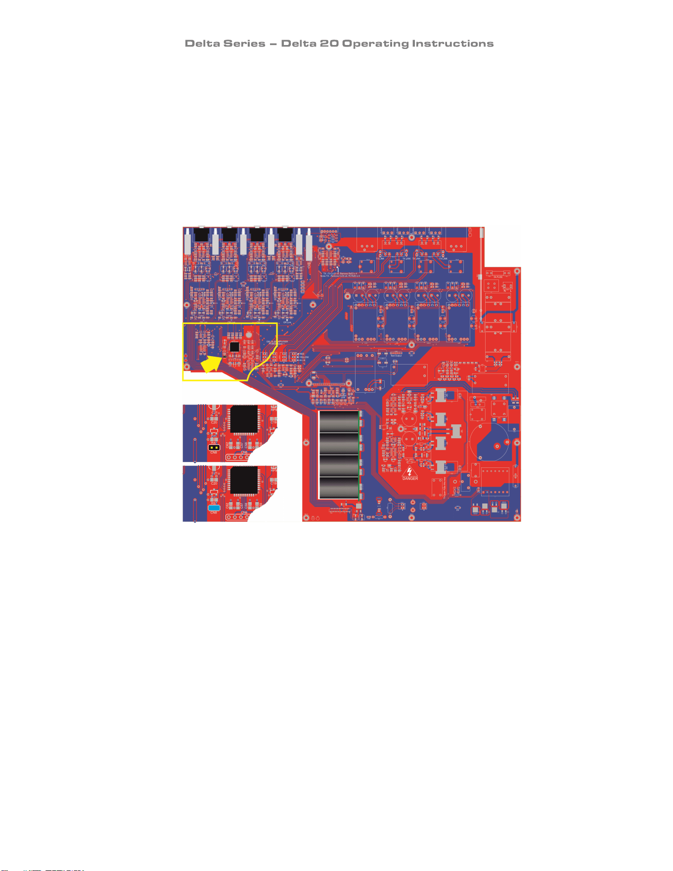
Internal Adjustments to Your Amplifier: Fixed fan speed
These instructions are for use by qualified personnel only. Before any routine maintenance,
please ensure that your amplifier is disconnected from the mains supply!
In noise sensitive environments, the auto-fan speed adjustment may be disabled. This will set
the fans to a low, less audible speed which will not vary considerably with temperature.
Please be aware that this will also therefore limit the amplifier’s ability to cool itself and so it
will instead reduce power output when high demands are placed upon it.
The feature can be enabled by changing an internal link, CN27, (labelled “High Power Link”) as
shown below:
CN27 open:
Fans are fixed
low speed.
CN27 linked:
Fans are
temperature
controlled.
Page 20
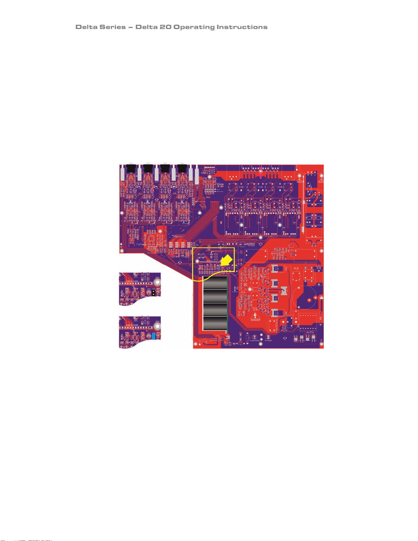
Internal Adjustments to Your Amplifier: Auto-standby mode
These instructions are for use by qualified personnel only. Before any routine maintenance,
please ensure that your amplifier is disconnected from the mains supply!
The Delta 20 will switch itself into standby after 10 seconds of no signal (less than -60dBu) on its
inputs. This feature is disabled by default and depends on the selected source – if analogue is
selected, this will be the source that can “wake” the amplifier up again, and if Dante is selected,
then this will control the auto-standby feature.
The feature can be enabled by changing an internal link as shown below:
CN8 op
en:
Auto-standby
disabled.
CN8 linked:
Auto-standby
enabled.
Page 21
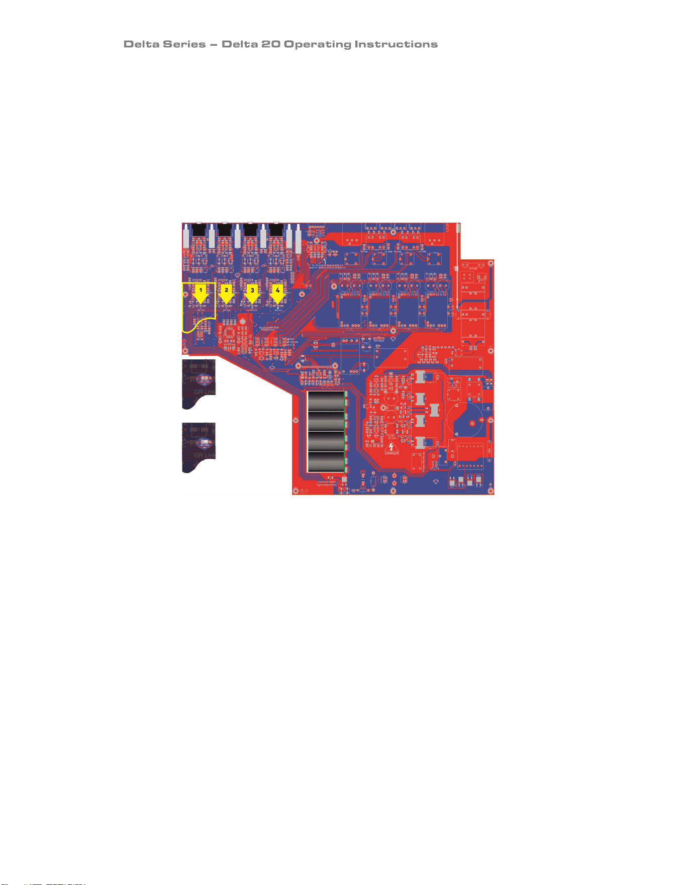
Internal Adjustments To Your Amplifier: Changing the Gain
These instructions are for use by qualified personnel only. Before any routine maintenance,
please ensure that your amplifier is disconnected from the mains supply!
Gain/Sensitivity Settings
Adjustment is by internal solder link as shown below – one link for each channel.
Channel A’s link is number 1 (SL102), channel B’s is number 2 (SL202) and so on.
The gain may be set to 20dB, or 26 (no link - factory default setting).
Remember, setting higher gain does not change the maximum available power but changes the
level of signal input to achieve maximum power. In any case, provided that the input signal is
less than 20dBu/7.7V, the built in limiter circuit will prevent distortion within the amplifier.
The gain should be set to match the signal level from the source – using the network audio
inputs will normally result in the amplifier running “hotter” than usual, so adding these links
and turning down the front panel attenuators will help.
Note that if 100V line output transformers are fitted then this link will be added as part of the
factory fit procedure, along with the enabling of the high pass filter to prevent transformer core
saturation.
We recommend changing all four channels together to avoid any confusion once the top cover
has been refitted!
SLX02
open:
Gain –
26dB.
SLX02
shorted:
Gain –
20dB…

Page 22
Looking After Your Amplifier: Maintenance
These maintenance instructions are for use by qualified personnel only. Before any routine
maintenance, please ensure that your amplifier is disconnected from the mains supply!
The filter behind the air intake apertures on the front of your amplifier should be cleaned or
replaced periodically, e.g. 3 -6 months. (Filters in amplifiers located in more 'dirty' atmospheres
may require more frequent maintenance).
The filter should be 'dry' cleaned, using a vacuum cleaner preferably. Running the unit without a
filter is not recommended. We recommend replacement of filters every 2-3 years, depending on
usage. Replacement filter material is available directly from us.
If the fan vents on the rear of the amplifier develop a build-up of dust/debris on the finger
guards, they can be cleaned with a dry paintbrush and a vacuum cleaner.
The casework of the amplifier may be cleaned with a lightly dampened cloth – do not use any
solvents as they will damage the paint finish and could remove printing.
If you have any doubts about carrying out maintenance, please refer to a service engineer or
contact your local dealer.
Looking After Your Amplifier: Warranty
Your amplifier is guaranteed for a period of five (5) years from the date of manufacture.
Please note that this does not apply to OEM versions of the amplifier – please consult your
manufacturer for their warranty terms. We hope that it gives you many more years of reliable
service than this, but should anything go wrong, please contact us to advise you about repairs or
any spares you might require.
Please do not attempt to repair the amplifier yourself as doing so will invalidate the warranty.
Our contact details are:
MC
2
Audio,
Units 6-8 Kingsgate
Heathpark Industrial Estate
Honiton, Devon
England
EX14 1YG
Tel: +44(0)1404 44633
Fax: +44(0)1404 44660
email: sales@mc2-audio.co.uk for general enquiries
Our website is a great place to get started if you have any questions regarding the general use of
your amplifier or need copies of this manual in digital form, or datasheets and photographs. The
datasheets also contain architect’s and engineer’s specifications.
www.mc2-audio.co.uk
Page 23
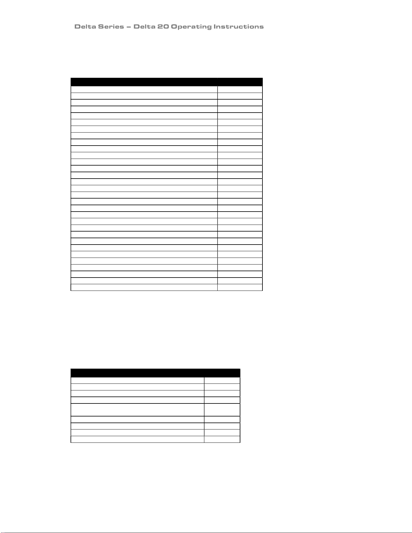
Performance Of Your Amplifier: Specifications
Main Specifications
Additional Specifications
Parameter (Units) Delta 20
Input Impedance
–
Active Balanced (Ohms)
1
0k
Input C
MRR (dB)
>
30
Damping Factor, 1kHz, 8 ohms
>
200
Signal Limiters Present
Yes
Protecti
on Present
–
Short Circuit / DC Ou
t
put /
Temperature
Yes
Mains In-rush Control Present Yes
High Impedance Transformer Outputs
Max voltage 50R load (Volts Peak)
145
Max voltage 50R load (Volts RMS)
103
Due to continuing product improvement, the above specifications are subject to change.
Parameter (Units) Delta 20
Output Power one channel [continuous music CF 4.8] (Watts)
2 Ohms
340
2.7 Ohms
480
4 Ohms
350
8 Ohms
175
50 Ohms [70/100V line TX]
200
Output Power all channels [continuous music CF 4.8] (Watts)
8 Ohms
175
4 Ohms
350
2.7 Ohms
480
2 Ohms
340
50 Ohms [70/100V line TX]
200
Output Power bridged pair [continuous music CF 4.8] (Watts)
8 Ohms
700
4 Ohms
660
THD+N, 4 Ohms (%)
@1kHz, 1dB below max output power <
0.01
@20Hz - 20kHz, 1dB below max output power <
0.03
Gain Options (dB) 26
Sensitivity Options for max power (dBu) 8.3
Sensitivity Options for max power (Volts) 2.0
Frequency Response, +0/0.3dB (Hz) 20 – 20000
Power Consumption, Nominal @ 240V, 4 Ohms (A) 0.74
Power Consumption, Nominal @ 120V, 4 Ohms (A) 1.53
Dimensions H x W x D (mm)
Amplifier
44 x 482 x 428
Boxed
100 x 580 x 590
Boxed Shipping – all except UK
140 x 610 x 600
Weight (kgs)
Amplifier (No TX)
5.1
Boxed – shipping
5.9
Page 24
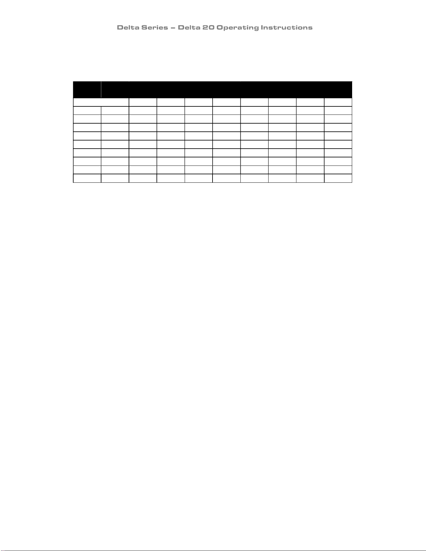
Performance Of Your Amplifier: Thermal Specifications
Power Consumption and Thermal Emissions – Delta 20
Mains
(V)
Load
(R)
Current Draw
(A)
Thermal Emissions
(W)
No Sig’l
Light
Average
Heavy
No Sig’l
Light
Average
Heavy
240 8
0.12 0.26 0.40 0.75 28 30 32 35
240 4
0.12 0.40 0.65 1.21 28 34 36 50
240 2.7
0.12 0.49 0.63 1.10 28 45 46 61
120 8
0.27 0.60 0.85 1.60 32 35 37 40
120 4
0.27 0.85 1.40 2.50 32 38 40 55
120 2.7
0.27 1.00 1.30 2.25 32 48 50 66
100 8
0.33 0.7 1.2 2 33 39 41 44
100 4
0.33 1 1.9 3.1 33 41 44 62
100 2.7
0.33 1.2 1.9 3 33 49 51 72
No Sig’l = Quiescent, Light = Crest Factor of 7.8(18dB),
Average = Crest Factor of 4.8(14dB), Heavy = Crest Factor of 2.8(9dB)
For details of measurement methods please refer to the Technical Support area of our website.
Page 25
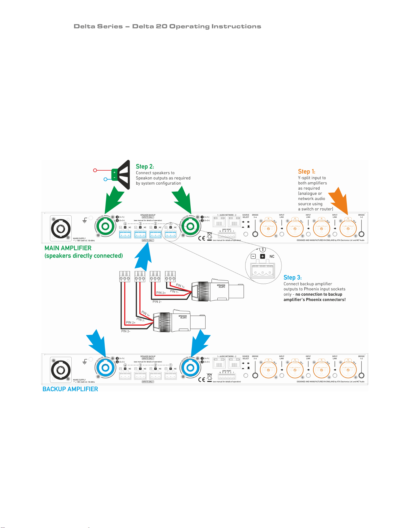
Appendix I: Speaker Backup Inputs
It is possible to configure a secondary amplifier as a backup device for use in safety-critical
applications, which will automatically be switched into circuit should there be a failure of the
main amplifier.
Failure could include loss of power, over-temperature protection or accidental remote enabling
of standby.
To use this feature, the backup amplifier must also be an MC
2
Delta 20, or an XTA DNA20. Do
NOT attempt to use another manufacturer’s amplifier or any Delta/DNA/DPA amplifier that is
not fitted with this feature.
Connect the two amplifiers as shown below:
Step 1: Connect both amplifiers’ inputs to the required sources and make sure both amplifiers
are configured the same for routing, and source (analogue/network).
Step 2: Connect speakers to the MAIN amplifier as normal in the required configuration.
Step 3: Connect link cables from the Speakon outputs of the BACKUP amplifier to the Backup
inputs of the MAIN amplifier, being careful to observe the correct polarity on the Backup inputs.
Two Phoenix connectors are wired to each Speakon for each pair of channels.
Both amplifiers must remain powered up and out of standby at all times. Should the main
amplifier fail, its output relays will disengage and in doing so, connect the outputs from the
backup amplifier directly to the Speakon speaker outputs via the Phoenix inputs.
Page 26
Appendix II: 70/100V line output operation
Your amplifier may be fitted with voltage step-up transformers enabling operation at higher
impedances for use with 70V or 100V line distributed speaker systems. This option is factory fit
only, and may be fitted to individual channels. Bridge mode should NOT be used once
transformers are fitted – you will not damage the amplifier, but the transformers will be
effectively bypassed when attempting to connect in bridge mode.
The option will also include a high pass filter to prevent saturation of the transformers at low
frequencies – this is standard practice for 70/100V line systems.
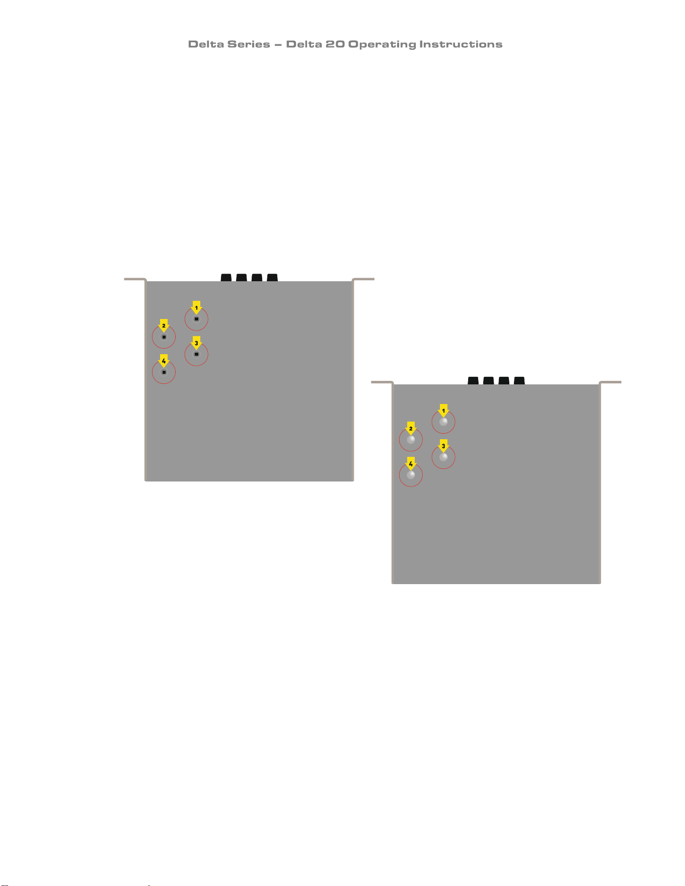
It may not be obvious if your amplifier has been fitted with transformers – the quickest way to
determine if this is the case is to check the base of the chassis – there are four indentations
towards the front left – if these are open with a square hole, no transformer is fitted.
If the indentations have silver bolt heads
in them then transformers are fitted to
this amplifier.
Please read Appendix III in this manual for some useful
background information on 70/100V line systems and
their use.

Page 27
Appendix III: 70/100V line distributed audio systems
Introduction
Distributed audio, particularly for speech applications, will often require many speakers to be
positioned around a venue, to provide even coverage at acceptable levels in all locations. These
speakers may be spread over a considerable area and involve long cable runs to achieve this.
Using low impedance “traditional” methods would introduce unacceptable losses due to the
actual resistance vs. the speaker impedance – it is easy to envisage a situation where the length
of the cable could cause 50% loss in available power.
Using heavier gauge cabling can go some way to reducing the losses, but this often is costly and
entirely impractical where many speakers are involved. Borrowing the method used to
distribute mains electricity across long distances, where mains supplies are stepped up (using
transformers) to higher voltages and stepped down for local consumption also works for
distributed audio.
This method helps because, as the voltage is increased, to achieve the same power delivery
there is a corresponding decrease in the current that must travel along the conductors. Lower
current requirements means thinner gauge cabling and lower losses due to the square law of
power delivery. Thinner gauge cabling therefore also means reduced costs, and lower amplifier
power requirements than if each speaker (or at best a few speakers) required an individual
amplifier channel.
How It Works
Firstly, a few misconceptions around the name of this method should be clarified. It is true that
the low voltage/higher current output of a standard audio amplifier is fed into a step-up
transformer to produce a higher voltage/lower current output that can travel longer distances
using thinner cables. This incurs fewer losses than a direct connection of a low impedance
speaker directly over the same distance.
However, the concept of this system operating at either a “constant voltage”, or “100V”, or “70V”
is slightly wrong. The system does NOT have a constant voltage output of any sort, unless a
constant level of audio is being fed into the amplifier (such as a sine wave), at which point the
output will be at a constant level. This would hold true in the low impedance (standard) case
too. There is no extra method of modulating a fixed voltage, or there being a permanent high
voltage output on the speaker lines.
The use of the terms “100V line” or “70V line” comes from the description of the system running
at full power output only. The transformer used to step up the voltage should be chosen so that,
when the amplifier is running at full power, the voltage across the lines will then be 100V (or 70V
or whatever has been deemed appropriate for the given application). The only thing that is
“constant” with this type of system is rated voltage at the amplifier’s rated power. So, whether
it’s a 30W amplifier for distributing speech to some horns by a racetrack, or a 300W amplifier
distributing music and announcements throughout a warehouse, both the systems will produce
100V (or whatever) when the amplifier is running at maximum power.
The majority of the time, the voltages present on the lines will be an order of magnitude less
than 100V, as the audio being delivered will be at a much lower level than full output (assuming
the amplifier chosen is up to the job!).
Page 28
AMPLIFIER OUTPUT VOLTAGE
STEPPED UP WITH TRANSFORMER
LONG SMALL GAUGE CABLE...
LOW V
HIGH I
HIGH V
LOW I
HIGH VOLTAGE STEPPED
DOWN AGAIN TO DRIVE SPEAKER
VIA LOCAL TRANSFORMER
LOW V
HIGH I
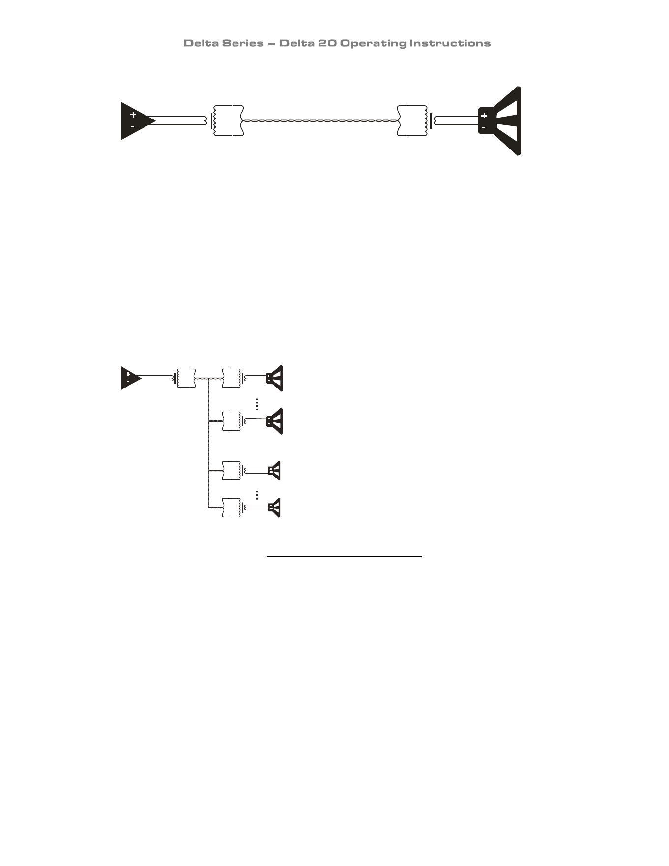
Once the voltage has been “stepped up” to the higher level for long distance transmission, when
it reaches the speaker, in common with mains power reaching its destination, there must be
some form of “stepping down” again to restore it to a voltage/current suitable for driving the
speaker. This is achieved by using a localised “step-down” transformer, normally attached
directly to the speaker chassis itself, or in the enclosure with the driver.
From this point on, the process for working out how many speakers can be connected to an
amplifier channel becomes relatively simple, but remember one thing – this doesn’t change the
laws of physics – just as there is a limit to how many speakers can be connected in parallel on a
“normal” channel of an amplifier, there is still a limit for 100V or 70V systems too!
Example: How many speakers can I connect to an amp channel?
We’ll start with an amplifier capable of supplying 200W to
a 100V line system. This total “pool” of 200W can be split
up any way we want to as many speakers as we want,
providing their requirements don’t exceed 200W in total.
The requirement of any particular 100V line configured
speaker is quoted as a power rating for a given SPL
output. Let’s say we have decided upon two sizes of ceiling
speaker for a given installation – one rated at 15W and one
rated at 5W. Ignoring the SPL ratings for now, it’s a
reasonable assumption to make that the “15W” speaker
will be generating a higher output level than the “5W”
speaker (for any given voltage on the line).
Remember – this wattage value isn’t the power rating of the driver – this is the power it will
consume from the amplifier – the speaker’s rating itself is not relevant (and is unlikely to be
quoted as part of the speaker’s specification).
So, to work out how many speakers the amplifier can handle, it’s as simple as adding up the
number of 15W speakers we want to use and the number of 5W speakers, and making sure this
total is no more than the 200W we have available.
AMPLIFIER IS RATED
TO PRODUCE 200W
FOR THE 100V
LINE SYSTEM
LOW V
HIGH I
200W
15W
15W
#1
#10
5W
#1
5W
#10

Page 29
Let’s say we have worked out that we need 10 of the 15W speakers, for starters – that comes to
10 x 15W = 150W, leaving us with 50W “spare”, which means we could connect another 10 of the
the 5W speakers. That’s 20 areas in total – not bad for just 200W!
This is in an ideal world of course…now for how it really works!
Calculating Real World Requirements
The choice of amplifier power, in an ideal world, would allow us to do this simple calculation and
everything to operate perfectly with the power available exactly matching the power delivered to
the speakers. However, this isn’t an ideal world, and there are two main factors that impede (!)
this from being true – losses in the cables themselves, and insertion losses in the step-up and
step-down transformers.
Whilst it is theoretically possible to calculate these losses, there is a “Catch 22” situation in play
here, which means that even measuring the real world losses through cables in a system
becomes impossible. Getting hold of insertion loss information for transformers is difficult, and
in order to measure the losses, you need to build the system, which you can’t do until you specify
your amp power, which you can’t do until you measure the losses!
Thus, there is a reliable “rule of thumb” that states that amplifier power should be
approximately 50% bigger than your speaker power requirements would suggest. So, if your
speakers total power comes to 100W per channel, go for an amplifier nearer 150W per channel
to account for all the losses and ensure you deliver the power and so SPL you require.
Getting The Best Performance
As 100V line systems are primarily intended for background music applications and foreground
delivery of speech program only, the necessity for the highest fidelity audio has never been
paramount. This does not mean that a carefully designed system can’t perform to a high audio
standard – it can, but there are certain constraints that need to be considered when evaluating
performance.
Due to the fact that transformers are in use throughout a 100V line systems, being careful not to
saturate the cores of these transformers with excessive energy is paramount to the system not
just working well, but not damaging the amplifier. Low frequency power tends to be the main
culprit for this condition, and a saturated transformer core appears as a very low impedance
across the amplifier’s output terminals, close to a direct short, resulting in early amplifier
overheating, protection circuits muting the audio unnecessarily and generally bad behaviour! It
manifests itself, in audio terms, as a distorted rasping sound - similar to how a misaligned voice
coil might sound.
Page 30
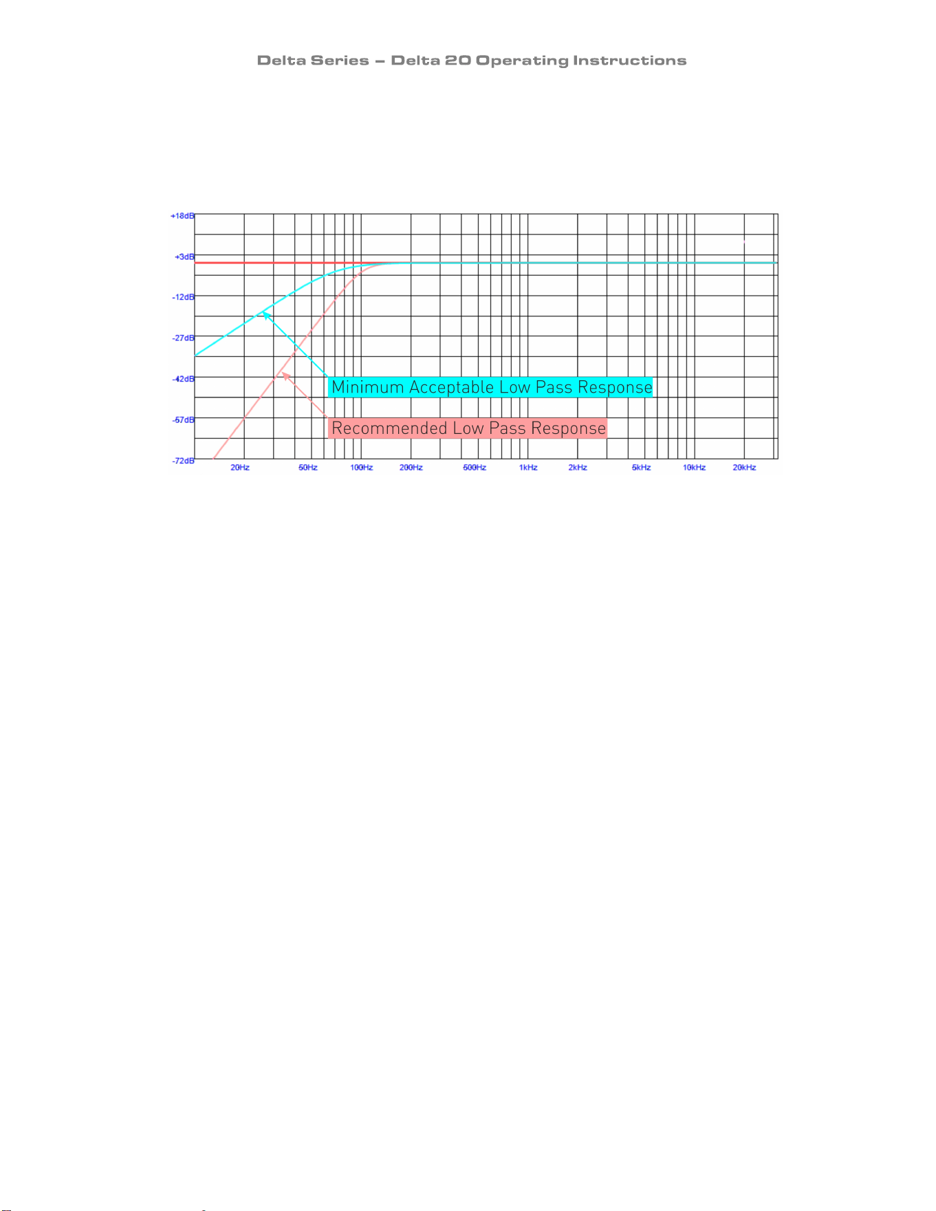
This can be easily avoided by ensuring that high pass filters are fitted to all channels to limit the
low frequency content of the system. We recommend fitting crossover cards to our amplifiers,
or inserting suitable filtering using an external speaker management system, such as the XTA
DP4 and 5 Series. The minimum response requirement is -3dB @ 70Hz and 12dB/Octave roll off
below this.
All ranges of MC
2
amplifiers can be fitted with these cards – please contact us for more
information.
Note that the Delta 20 has a built-in HPF (100Hz HPF with a roll-off of 24dB/Octave
Butterworth) which is enabled as part of the procedure when the step-up transformers are
fitted – it does not use the crossover card insert points – these are still free for other use.
Working Without Step-Up Transformers
In most circumstances, the power output of amplifiers used in 100V line systems is only in the
order of a few hundred watts, due to the total power requirements of the multiple small
speakers being installed only reaching this sort of figure.
However, higher powered amplifiers are capable of generating a voltage swing sufficient to drive
a 100V system without the need of a set-up transformer. There may be circumstances when
using a larger amplifier is required – for instance when the amplifier’s usage is being split to
provide distributed audio on one channel and local higher power on another (perhaps for a sub-
bass system) or if there is an unusually large number of higher power 100V line speakers on the
system.
The following MC
2
amplifiers may be used without a step-up transformer – as mentioned earlier,
whilst their maximum output voltage may not reach 100V, they are capable of being operated
transformerless if required.
Note this refers only to the step-up transformer at the amplifier – the speakers will still require
their individual step-down transformers. MC
2
also still advise using a high pass filter on
channels driving a 100V line system.

Page 31
T & Ti Series
3500: 90v
2000: 70v
1500: 130v bridged nearly 65v normal.
1000: 115v bridged
E Series
90: 140v
100: 105v
45: 100v
60: 80v
25: 75v
15: 120v bridged
475: 80v in 8 ohm mode, 120v bridged 4 ohm
mode
In Conclusion…
Working with distributed audio using the 100V line system need not be a complex undertaking –
just remember these key points:
- If in doubt about how much power you need, go for your upper estimate – an underpowered
system will perform worse in all circumstances, not just when the system is being driven hard!
- Always fit high pass filtering on each amplifier channel to prevent premature amplifier failure
and circumvent poor audio performance.
MC
2
manufacture a
special external 100V line transformer system for use with certain T and Ti
Series models – this product is called “T-Line” and can be loaded with a variety of transformers
according to system requirements. More information on this is on our website here:
http://www.mc2-audio.co.uk/images/stories/datasheets/tseries/tline_datasheet.pdf