
Thank you for purchasing our products. Please review this manual thoroughly before operating your device.
All pictures in this manual are for illustration purpose only. Actual product may vary due to product upgrade.
DK09
Smart Lock
Installation Guide / Programming Instructions

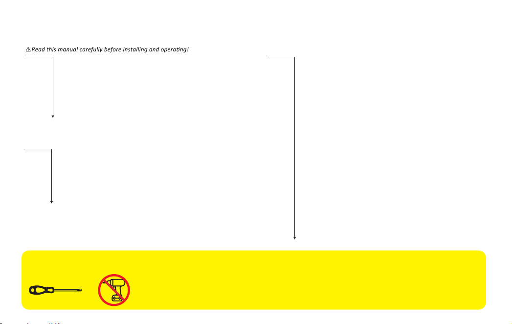
TOOL REQUIRED:
Do not use an electric screwdriver during installation.
Installation Overview
STEP 1: Prepare the door and check dimensions
STEP 2: Install the latch and strike
STEP 3: Install exterior assembly
STEP 4: Install interior assembly
P 3
P 4
P 6
P 7
Programming Instructions
P 9
P10
P 11
At a Glance
How to Use
Definitions
DDLock Use Guide
P 12
P13
P 14
P 15
P 16
P 17
P 18
P 19
P 21
P 22
P 23
P 24
HOW TO REGISTER
Pairing Your Lock
Admin Passcode Management & Lock Page Overview
APP Unlock / Lock & Passcode
IC Card & Fingerprints
eKeys & Authorized Admin
Passage Mode and Auto-Lock & Lock Settings
Quick Set Up
Factory Default Settings
Troubleshooting
FCC Statement
Information & Safety Warnings
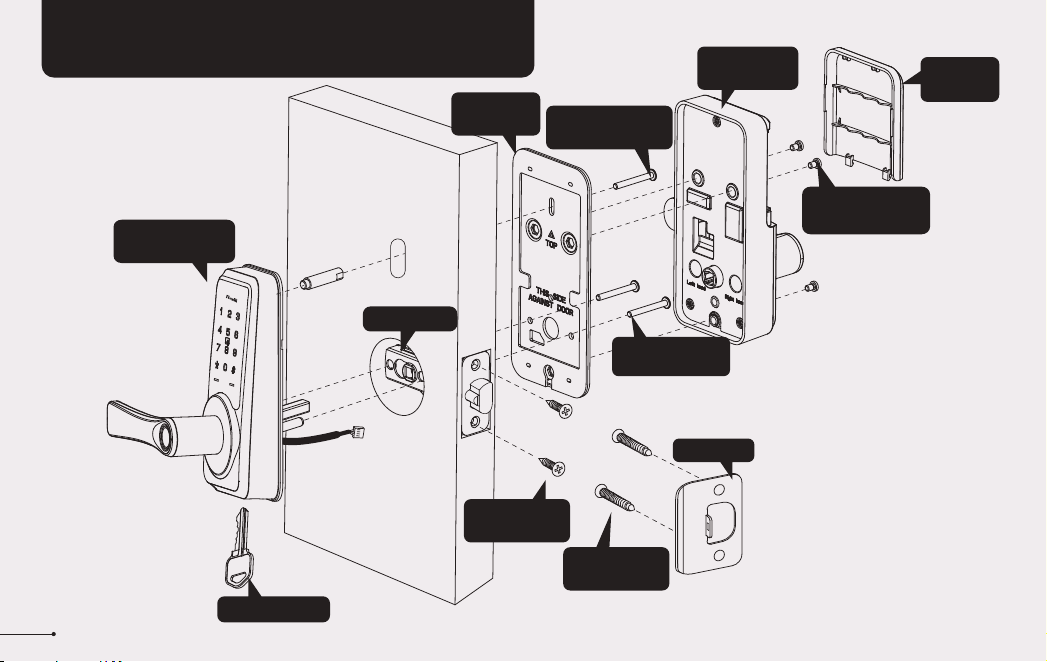
INSTALLATION INSTRUCTION
1
Interior Assembly
Screws (L)
Strike (D)
Mounting
plate (E)
Backup key (A)
Exterior Assembly
(B)
Exterior Assembly
Screw (F)
Latch (C)
Interior
Assembly (G)
Battery
Cover (H)
Strike Screws
(I)
Latch Screws
(J)
Mounting
plate Screws (K)
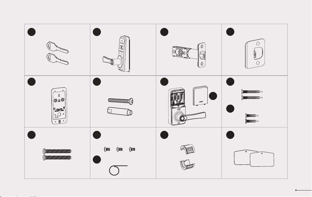
Latch x1
Strike x1
Exterior Assembly x1
Mounting Plate x1 Exterior Assembly
Screw (Optional)
Strike Screws x2
Mounting Plate Screws x2
Latch Screws x2
A B C
E F I
J
K
D
Parts List
If any parts are missing or damaged, please contact Customer Support.
2
Interior Assembly x1
Battery Cover x1
G
H
Interior Assembly
Screws x3
L
M
Reset Tool x1
Drive-In Collar (Optional)
N
IC Card x2
O
Backup Key x2
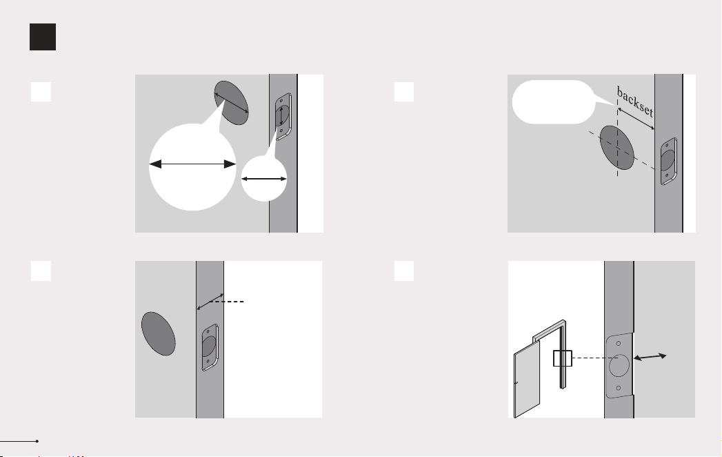
Measure to confirm
that the hole in the
door edge is 1"
(25mm).
Measure to confirm
that the backset is
either 2-3/8" or
2-3/4" (60 or 70mm)
2-3/8" or 2-3/4"
(60 or 70mm)
Make sure the hole in
the door frame is
drilled a minimum of
1’’ (25mm) deep, to
leave enough space
for the latch to extend
into the door frame
when the door is
locked.
Measure to confirm
that the door is 1-3/8"
to 2" (35mm to
50mm) thick.
A
Measure to
confirm that the
hole in the door is
2-1/8" (54mm)
B
C
D
Prepare the door and check dimensions
1
STEP
3
1"
25mm
1-3/8" to 2"
(35mm to 50mm)
2-1/8"
(54mm)
1"
25mm
Make sure the door frame is aligned with the door.
There are no obstructions stuck in the door frame.
Notes:
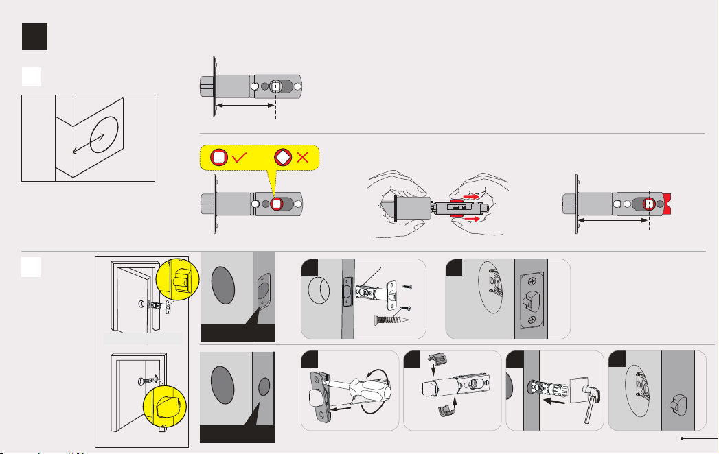
2
4
3
chiseled
not chiseled
Install the latch and strike
2
STEP
Backset is the distance from the door
edge to the center of the hole in the door.
The latch is provided with adjustable
design which can fit either 2-3/8’’(60mm)
or 2-3/4’’(70mm) backset.
A
B
Latch backset adjustment
Install the latch
2-3/8"
(60mm)
2-3/4"
(70mm)
If the backset of your door is
2-3/8"(60mm), no need to adjust
the latch.
If the backset of your door is 2-3/4"(70mm), please adjust the latch.
2
Latch Screws (J)
C
1
1
4
Drive-In Collar(N)
Opening inwards
Opening outwards
C
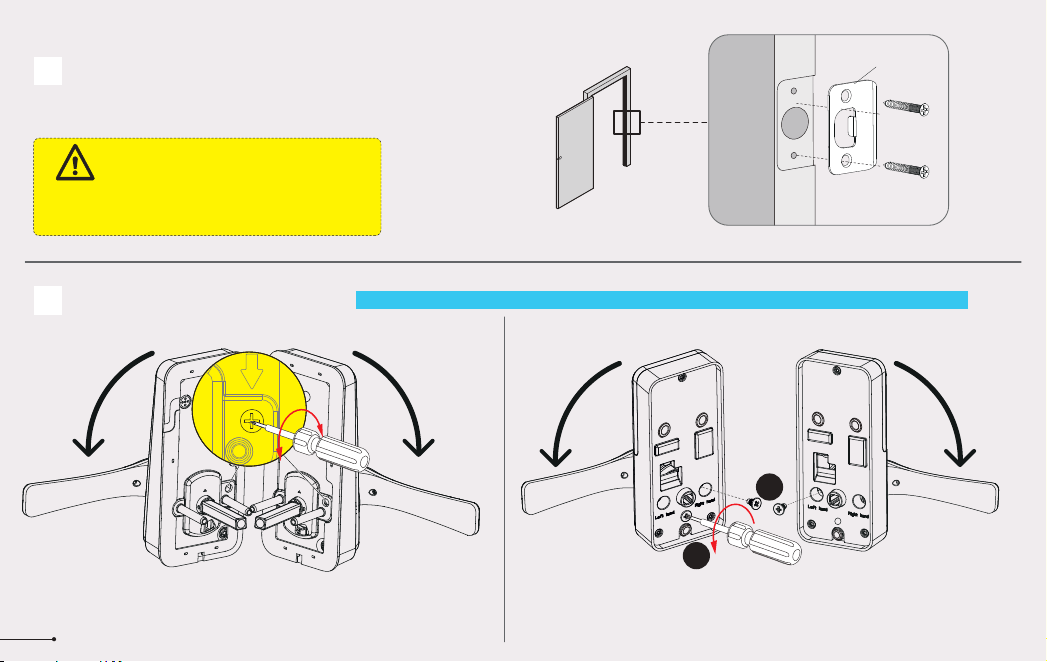
Install strike on the door frame.
D
Change Handle Direction (Optional)
Make sure the hole in door frame is
drilled a minimum of 1" (25mm) deep.
IMPORTANT:
5
Change the Handle direction of exterior assembly. Change the Handle direction of interior assembly.
Loosen the screw completely and remove the screw by using a
screwdriver. Rotate the handle to the other side and keep the handle
horizontal. Tighten the screw in the Left-hand or Right-hand screw holes
according to the actual handle direction.
Loosen the reversing screw by using a screwdriver. Rotate
the lever to the other end and keep it horizontal. Tighten the
reversing screw.
1
2
The handle direction can be changed for compatible with both right handed and left handed doors.
Notes:
Strike Screws (I)
D
A B
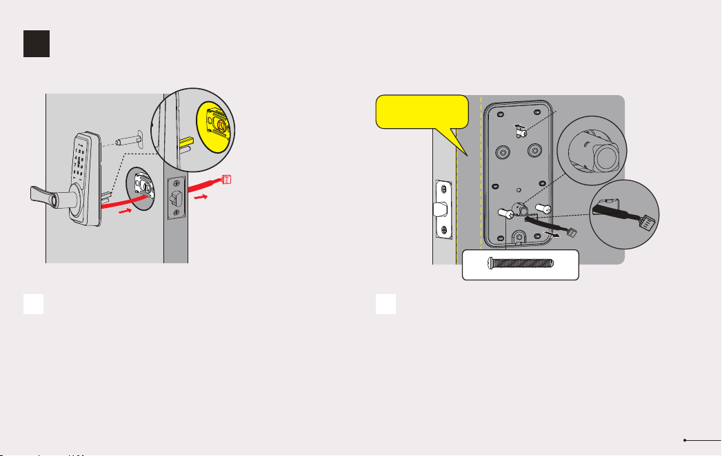
Install exterior assembly
3
STEP
Route the cable below the latch, and insert the
torque blade through the slot in the latch.
Secure the mounting plate with the supplied screws.
Do not overtighten screws.
Keep parallel to
door edge.
Mounting plate Screws(K)
6
Exterior Assembly
Screw (F) (Optional)
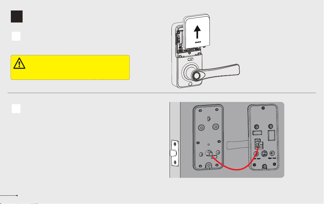
Install interior assembly
4
STEP
Do not load batteries until lock is completely installed.
IMPORTANT:
A
7
Push the battery cover out in the direction as illustrated.
B
Insert the cable connector to the socket. Push the connector in firmly
until it is completely attached.
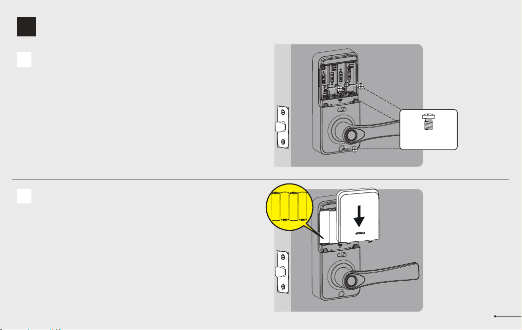
8
Install interior assembly
4
STEP
Insert 4 AA Alkaline batteries and put on the
battery cover.
D
Attach Interior Assembly to Mounting Plate and
tighten 3 Screws.
C
Interior Assembly
Screws (L)
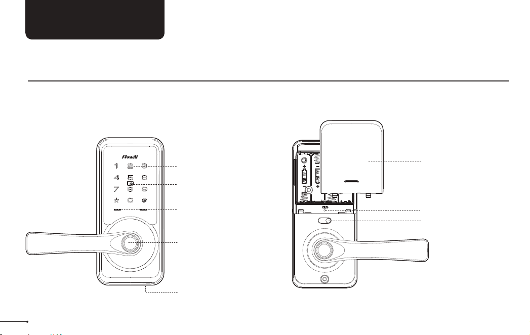
USER GUIDE
At a Glance
Exterior Assembly Interior Assembly
9
Keypad
IC card Touch Area
Fingerprint
Keyhole
Indicator Lights
Reset Button
Passage Switch
Battery Cover
How to Lock / Unlock
UNLOCK the door from outside
LOCK the door from outside
UNLOCK the door from inside
LOCK the door from inside
10
Auto Lock Mode
In Auto Lock Mode,
the lock will
automatically move to
locked position after 5
seconds, then the
lever can’t be turned.
Auto Lock Mode
In Auto Lock Mode,
the lock will
automatically move to
locked position after 5
seconds, then the
lever can’t be turned.
Tap and hold Lock icon in
App to lock.
Manual Mode
Press # on keypad
for 2 seconds.
4
Right Hand
Card or
Backup Key
Left Hand
• Master Code
Required for programming user codes, fingerprints and IC card. The
default master code needs to be changed before programming.
After pairing DDLock App successfully, the master code will be
changed to a random 7 digit number, and you can change it to your
own master code in App.
• Auto Lock & One-touch Lock
Automatically locks the latch after the door closed in 5 seconds. Auto
Lock is disabled by default. The Auto Lock time can be customized
between 1 and 900 seconds.
One-touch Lock is pressing and holding "#" on the touch keypad for 2
seconds to lock from outside.
• Wrong Entry Limit
After 5 times unsuccessful attempts at entering an invalid password,
the device will shut down for 2 minutes.
• Passage Mode
Move the Passage Switch to enable and disable the Passage Mode.
Enable Passage Mode, the lock will stay Unlocked until it’s locked
manually.
In Passage Mode, Auto-lock will be disabled.
• Anti-peeping password
Entering random numbers before or after correct password will also
unlock the door, which can prevent the password being exposed.The
length of anti-peeping password should be within 16 digits.
Definitions
11
The DDLock app is needed to use
this lock. If this lock was
professionally installed (or installed
by someone other than the
homeowner), make sure this step is
performed by the homeowner.
Notes:
DDLOCK USE GUIDE
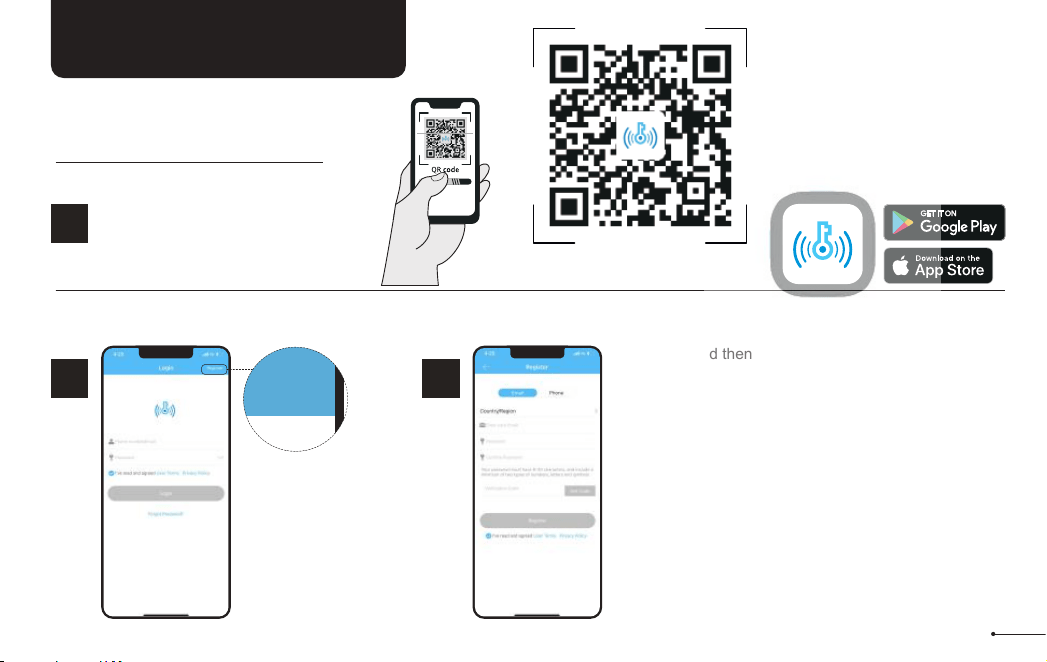
Tap on register
to get started!
1
STEP
Register
2
STEP
Fill out this and then
tap “Get Code”.
You will be sent a
verification code to
verify your account !
Once you receive it,
tap on “Register”
Download “DDLock” App in
Google Play or App Store.
HOW TO REGISTER
1
STEP
Scan QR code to download
DDLock App
12
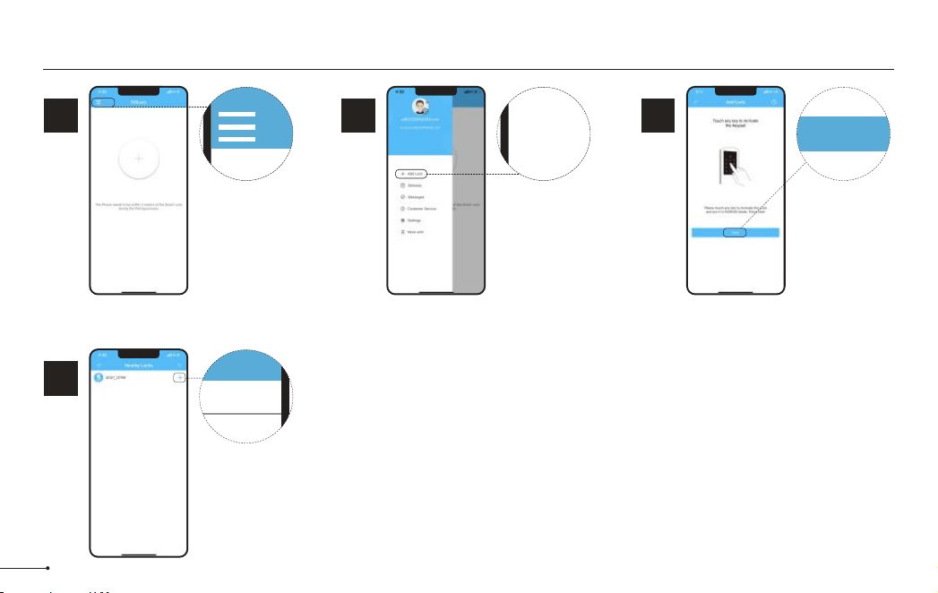
Pairing Your Lock
Tap on the three
horizontal lines.
1
STEP
Tap on
“+ Add Lock”.
2
STEP
3
STEP
+ Add Lock
4
STEP
Tap on “Next”.
Next
Tap on the blue
plus sign.
+
You may need to tap
on lock keypad.
Notes:
13
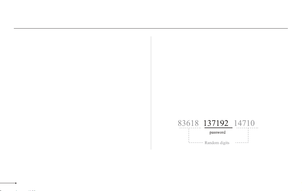
After pairing the lock with DDLock, the admin
passcode will be changed to a random 7 digit
number, you can check the new admin passcode
by following the picture guide below. And you can
change it to your own administrator password.
Some of these icons may not appear if the Gateway is not connected to the lock.
Notes:
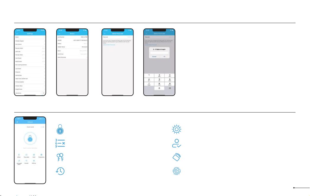
Admin Passcode Management
Cards
Set up your cards here
RF
Fingerprints Page
Set up fingerprints
Settings Page
View and modify settings
Authorized Admin Page
Create and edit admins
Unlock/Lock
Unlock/Lock using phone’s bluetooth
Records Page
View entry times, attempts and methods
eKey Page
View and modify current eKeys
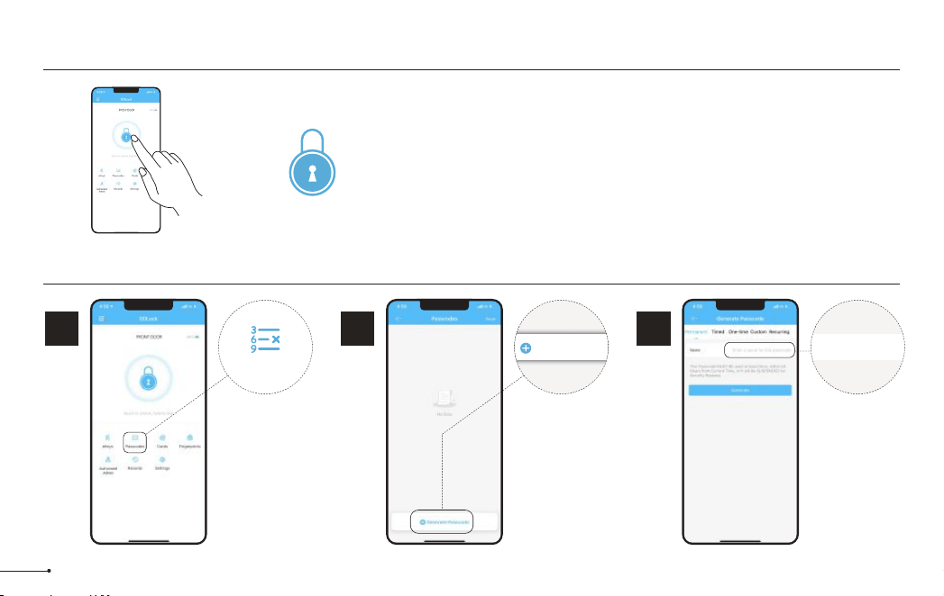
Passcode
Generate 6 different types of passcodes
Lock Page Overview
14
To unlock the lock, tap this icon once.
To lock the lock, press and hold on this icon.
APP Unlock / Lock
Passcode
1
STEP
To access the
passcode menu,
tap on “ Passcode”
icon.
This will take you
to the passcode
page.
Passcodes
2
STEP
Tap on
“Generate
Passcode”.
Generate Passcode
Enter a name for this Passcode
3
STEP
Enter a name for
this Passcode.
15
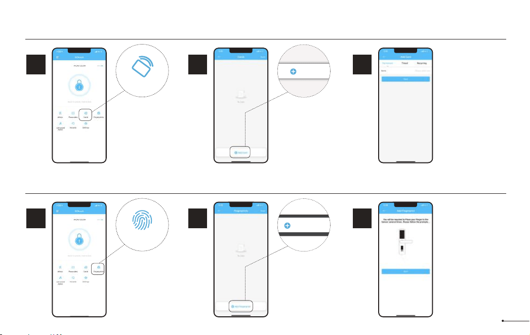
RF
IC Card
1
STEP
Tap on “Cards”.
Cards
2
STEP
Tap on “Add
Card”.
3
STEP
Choose the validity
period of the lock.
Once the lock says
“Please swipe your
card", place the
card against 5 on
the keypad.
If you hear a long
beep, the card can
be used to unlock
your lock.
Add Card
Fingerprints
1
STEP
Tap on
Fingerprints.
Fingerprints
2
STEP
Tap on “Add
Fingerprints”.
3
STEP
Select Fingerprint
type depending on
when you would
like it to be valid.
Follow instructions
on app. You will be
asked to place your
finger on the
sensor 4 times.
Add Fingerprints
To add a fingerprint follow these instructions:
16
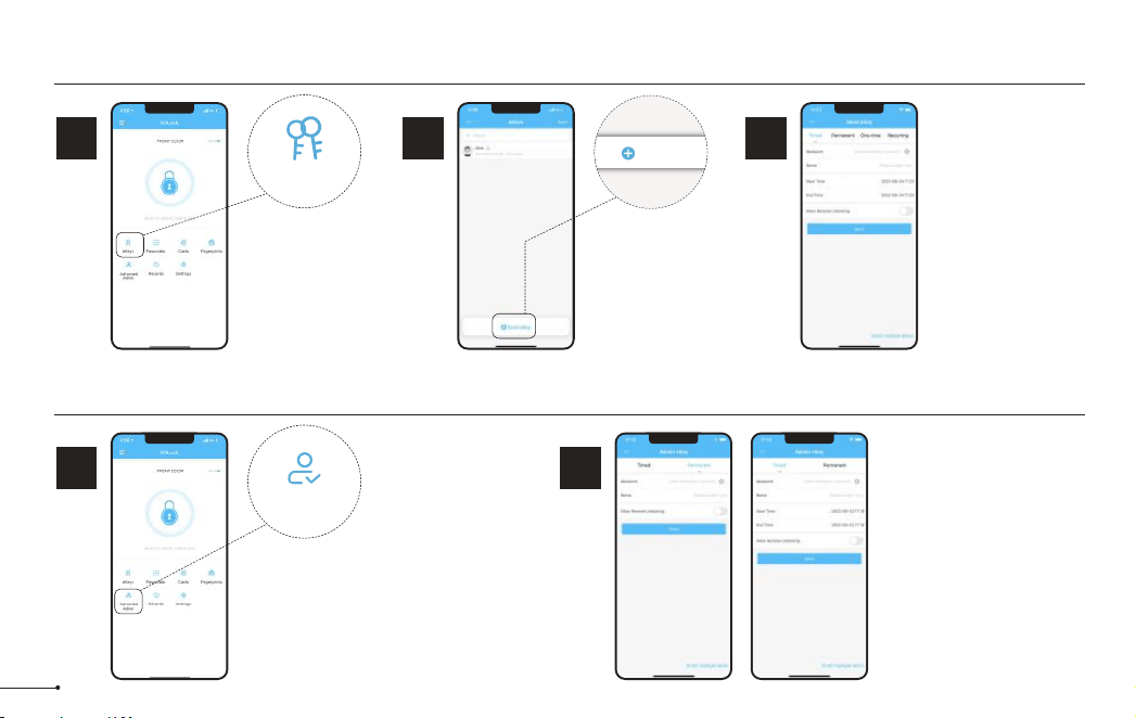
eKeys
1
STEP
eKeys work by sharing app
access of your lock with
another DDLock account.
eKey recipients will be
able to use their phone to
unlock/lock the lock.
eKeys
2
STEP
Tap on “Send
eKey”.
3
STEP
Enter recipient’s
username. It will be
the phone number or
email address during
registration.
eKeys do not require
wifi or bluetooth to be
sent or revoked.
Send eKey
Authorized Admin
1
STEP
1. Unlock/lock via the app.
2. Generate, Edit, Delete
passcodes, IC cards, &
fingerprints.
3. Adjust settings like passage
mode, auto-lock timer, & turn
on/off the lock sound.
Authorized Admin
2
STEP
Tap on “Authorized
Admin” Set Timed Admin
or Permanent Admin.
Authorized Admins are similar to eKeys; however, an authorized admin can do the following:
17
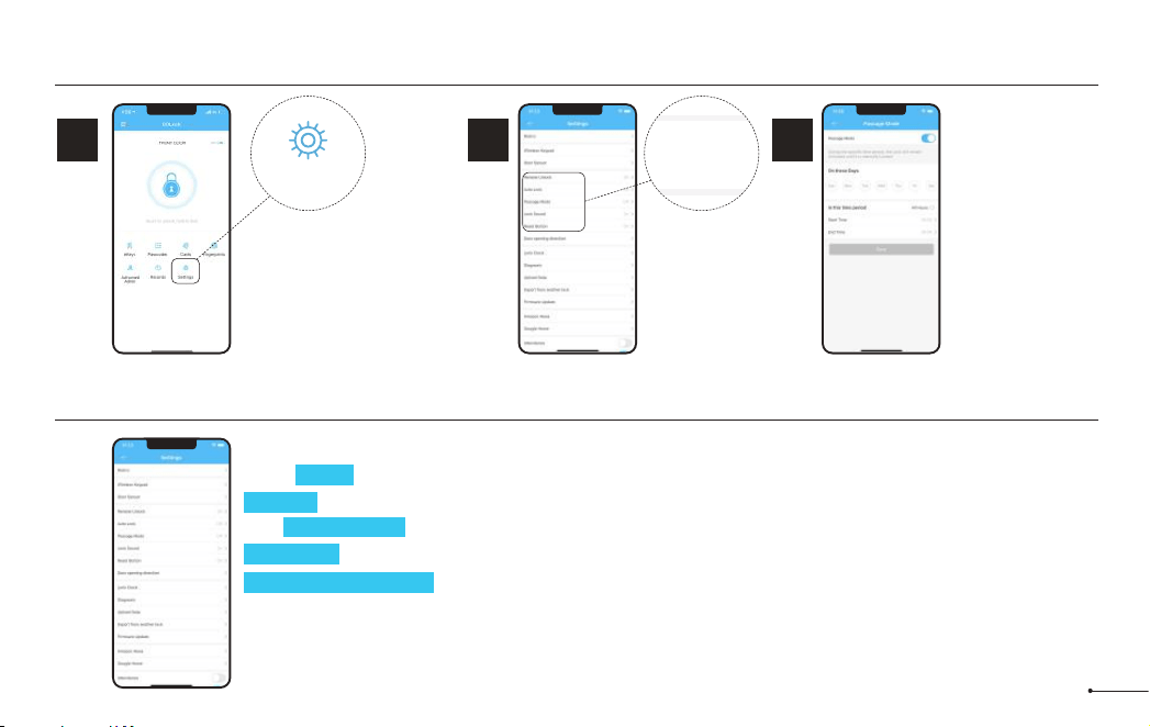
Passage Mode & Auto-Lock
1
STEP
Auto-lock will automatically lock
the lock when it has be opened
after 5 seconds by default. This
can be adjusted with Passage
Mode and Auto-lock timer.
Outlined below is how to adjust
these settings related to auto-lock.
Select Passage
Mode.
Settings
2
STEP
3
STEP
Passage Mode
disables auto-lock
during a set
schedule.
Lock Settings
Settings
Basics
Wireless Keypad
Door Sensor
Remote Unlock
Auto Lock
Passage Mode
Lock Sound
Reset Button
Here are some settings you should familiarize yourself with.
Under Basics, you can view and change information such as Lock Name.
Gateway shows signal strength if Gateway is connected.
With Remote Unlock on and a Gateway connected, you can remotely unlock/lock your lock.
Lock Sound adjusts the locks sound level.
Import from another lock allows for the transfer of passcodes and cards from one lock to another.
Delete will remove the lock from your account and clear any settings one the lock. You must be near the lock to
do this.
18
Support to add 13.56MHz
cards, such as mifare card,
NFC card, Desfire card and
EV1 card.
Notes:
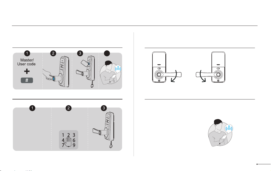
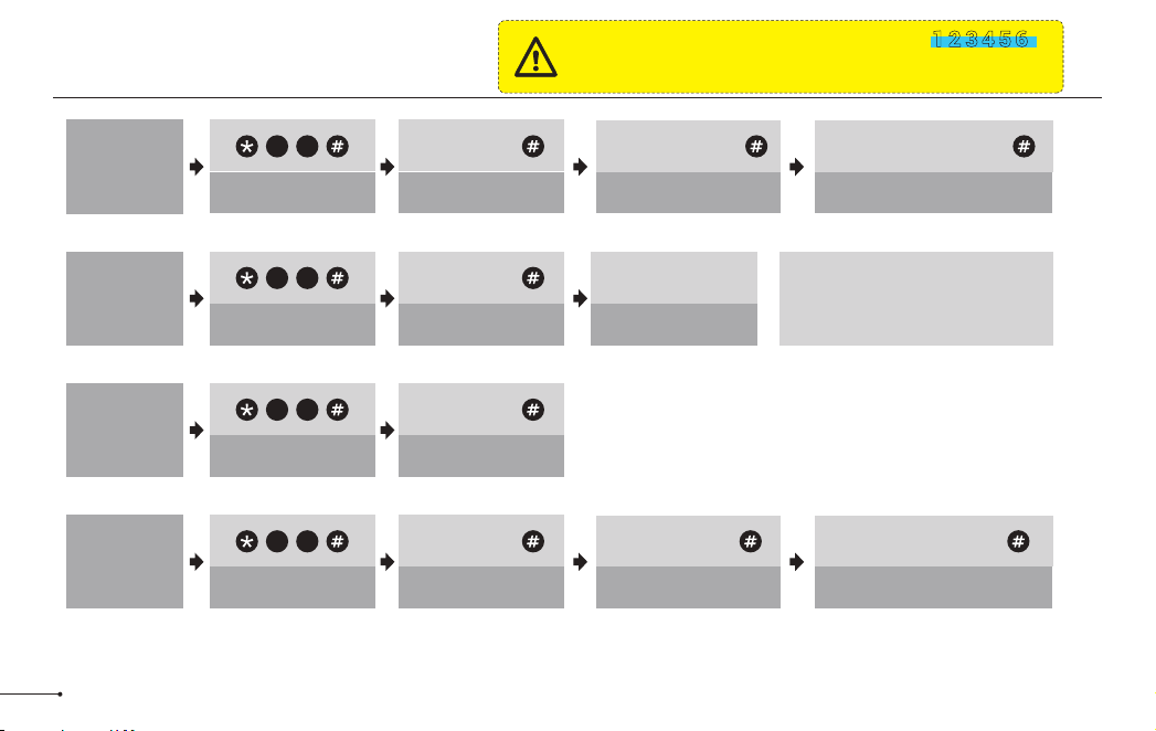
Programming Guide
The default Master Code is 123456.
It is required that you change it to a code of
your own before programming.
IMPORTANT:
3 beeps 3 beeps
Change
Master Code
2 Long beeps+2 Green
light flash
3 beeps
Master Code +
3 beeps
Master Code +
New Master Code +
Same New Master Code +
1 2
3 beeps 3 beeps
Add User
Code
2 Long beeps+2 Green
light flash
3 beeps
Master Code +
New User Code + Same New User Code +
8 0
Master Code +
3 beeps
Delete All
User Card
6 9
2 Long beeps+2 Green
light flash
3 beeps
Add User
Card
1 Long beep +1 Green
light flash
Scan User Card
8 0
19
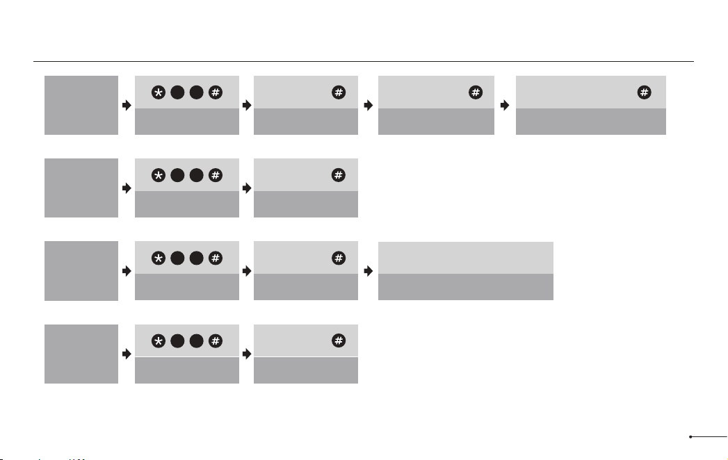
3 beeps 3 beeps
Change
User Code
2 Long beeps+2 Green
light flash
3 beeps
New User Code + Same New User Code +
1 0
Unwanted user
Code +
3 beeps
Delete All
User Code
7 1
Master Code +
2 Long beeps+2 Green
light flash
3 beeps 3 beeps
Add
Fingerprint
1 Long beep +1 Green light flash
Master Code +
8 0
Scan 4 Times Fingerprint (Each time
succeed along with a short beep)
3 beeps
Delete All
Fingerprint
7 0
2 Long beeps+2 Green
light flash
Master Code +
Programming Guide
20
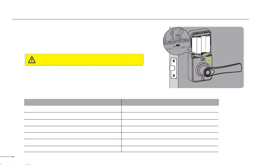
Factory Default Settings
The Reset Button must be turned on in DDLock
App before resetting.
IMPORTANT:
How to Reset?
Press and hold the Reset button on the interior assembly for 5 seconds
by using the Reset tool, until you hear a short beep and Green light
flashes once.
Settings
Master Code
Auto Lock
Passage Mode
Reset Button
Lock Sound
Wrong Code Entry Limit
Shutdown Time
Reset button
Factory Defaut
123456
5S
Off
On
On
5 times
2 minutes
21

Troubleshooting
Q: Why the lock won’t accept any inputs after I entered a code or fingerprint incorrectly for so many times?
A: The lock will shut down for 2 minutes after 5 unsuccessful attempts at entering an invalid code or fingerprint.
You can unlock the lock once in the App or wait 2 minutes to continue.
Q: How do I lock manually from outside?
A: Press and hold # to lock the lock from outside.
Q: The batteries are completely dead before I replace new batteries.
A: When the batteries are completely dead, the physical keys are available to unlock.
Q: How do I share access of the lock to my family members?
A: Go to DDLock App, in eKeys or Authorized Admin, it can share access of the lock to your family.
22

FCC Statement ISED Statement
This equipment has been tested and found to comply with the limits for a
Class B digital device, pursuant to part 15 of the FCC Rules. These limits
are designed to provide reasonable protection against harmful
interference in a residential installation. This equipment generates, uses
and can radiate radio frequency energy and, if not installed and used in
accordance with the instructions, may cause harmful interference to radio
communications. However, there is no guarantee that interference will not
occur in a particular installation. If this equipment does cause harmful
interference to radio or television reception, which can be determined by
turning the equipment off and on, the user is encouraged to try to correct
the interference by one or more of the following measures:
• Reorient or relocate the receiving antenna.
• Increase the separation between the equipment and receiver.
• Connect the equipment into an outlet on a circuit different from that to
which the receiver is connected.
• Consult the dealer or an experienced radio/TV technician for help.
Caution: Any changes or modifications to this device not explicitly
approved by manufacturer could void your authority to operate this
equipment.
This device complies with part 15 of the FCC Rules. Operation is subject
to the following two conditions: (1) This device may not cause harmful
interference, and (2) this device must accept any interference received,
including interference that may cause undesired operation.
RF Exposure Information
This equipment complies with FCC radiation exposure limits set forth for
an uncontrolled environment. This equipment should be installed and
operated with minimum distance 20cm between the radiator and your
body.
English: This device contains licence-exempt transmitter(s)/receiver(s)
that comply with Innovation, Science and Economic Development
Canada’s licence-exempt RSS(s). Operation is subject to the following
two conditions:
(1) This device may not cause interference.
(2) This device must accept any interference, including interference that
may cause undesired operation of the device.
The digital apparatus complies with Canadian CAN ICES‐3
(B)/NMB‐3(B).
French: Cet appareil contient des émetteurs/récepteurs exempts de
licence qui sont conformes aux RSS exemptés de licence d'Innovation,
Sciences et Développement économique Canada.
L'exploitation est soumise aux deux conditions suivantes :
(1) Cet appareil ne doit pas provoquer d'interférences.
(2) Cet appareil doit accepter toute interférence, y compris les
interférences susceptibles de provoquer un fonctionnement indésirable
de l'appareil.
l'appareil numérique du ciem conforme canadien peut‐3 (b) / nmb‐3 (b).
This device meets the exemption from the routine evaluation limits in
section 2.5 of RSS 102 and compliance with RSS 102 RF exposure,
users can obtain Canadian information on RF exposure and compliance.
cet appareil est conforme à l'exemption des limites d'évaluation courante
dans la section 2.5 du cnr - 102 et conformité avec rss 102 de l'exposition
aux rf, les utilisateurs peuvent obtenir des données canadiennes sur
l'exposition aux champs rf et la conformité.
This equipment complies with Canada radiation exposure limits set forth
for an uncontrolled environment.
Cet équipement est conforme aux limites d'exposition aux rayonnements
du Canada établies pour un environnement non contrôlé.
This equipment should be installed and operated with minimum distance
20cm between the radiator & your body.
Cet équipement doit être installé et utilisé à une distance minimale de 20 cm
entre le radiateur et votre corps.
23

24
• Protect your User Codes and Master Code.
• Restrict access to your lock’s interior assembly and routinely check your
settings to ensure they have not been altered without your knowledge.
• Do not use an electric screwdriver during installation.
• This manufacturer advises that no lock can provide complete security by
itself.
• This lock may be defeated by forcible or technical means, or evaded by
entry elsewhere on the property.
• No lock can substitute for caution, awareness of your environment, and
common sense.
• Care should be taken to ensure a long-lasting finish. When cleaning is
required use a soft, damp cloth. Using lacquer thinner, caustic soaps,
abrasive cleaners or polishes could damage the coating and result in
tarnishing.
• The lock is water resistant. It can withstand water splashes; however,
do not let water and liquids get into the lock.
• Avoid exposure to direct sunlight. Long-term exposure to direct
sunlight may damage the lock.
Information & Safety Warnings

V3.0
2022-11-02
DK09说明书(中性)
166x105mm
105g双铜纸
四色双面印刷;骑马钉
成品尺寸:
材 质:
工 艺:
备 注:
物料名称:
时 间:
设 计:
料 号: