R
Grid-tied PV String Inverter
User Manual
1. Introduction
1.1 Appearance introduction
1.2 Parts list
2. Safety warnings and instructions
2.1 Safety signs
2.2 Safety Guide
2.3 Notes for using
3. Operation interface
3.1 Interface view
3.2 Status indicator
3.3 buttons
3.4 LCD dispaly
4. Product Installation
4.1 Select installation location
4.2 Recommened place
5. Electrical connection
5.1 DC input connection
5.2 AC input connection
6. Start up and shut off
6.1 Start up the inverter
6.2 Shut off the inverter
- 1 -
- 1 -
- 2 -
- 3 -
- 3 -
- 3 -
- 4 -
- 5 -
- 5 -
- 5 -
- 6 -
- 6 -
- 7 -
- 7 -
- 9 -
- 10 -
- 11 -
- 11 -
- 13 -
- 18 -
- 18-
- 18 -
…………………………………………………………
……………………………………………
…………………………………………
………………………………………………………
…………………………………………………………
………………………………………………………
……………………………………………………
……………………………………………………
……………………………………………………
…………………………………………………………
……………………………………………………
……………………………………………………………
………………………………………
…………………………………………………
…………………………………………………
…………………………………………………
- 16 -
…………………………………
………………………………………………
………………………………………………
……………………………………………………
………………………………………………
7. Limiter function
- 19 -
………………………………………………………
7.1 Limiter function wiring diagram
7.2 Connect the limiter to inverter
- 19 -
- 20 -
………………………………………
………………………………………
- 26 -
- 38 -
- 38-
……………………………………………………
………………………………………
…………………………………………………………
…………………………………………………
- 23 -
7.4 Zero-export function (Option)
7.3 Debugging Limiter
- 24 -
………………………………………
…………………………………………………
8.1 The initial interface
8.2 Statistics information
- 26 -
- 29 -
…………………………………………………
………………………………………………
8.3 Fault Record
8.4 ON/OFF setting
- 31 -
- 32 -
…………………………………………………………
……………………………………………………
8.5 Parameter setting
- 33 -
……………………………………………………
8. General Operation
9. Repair and Maintenance
- 38 -
10.1 Error code
- 43 -
…………………………………………………………
10. Error information and processing
11. Specifications
……………………………………………………
…………………………………………………
4.3 Installation of inverter
5.3 The connection of the ground line
- 16 -
……………………………………
5.4 Inverter monitoring connection
- 01 -
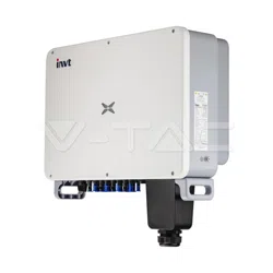
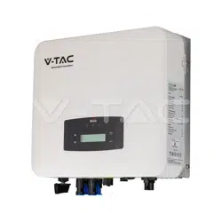
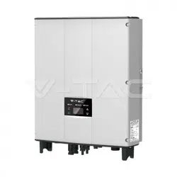
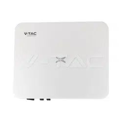
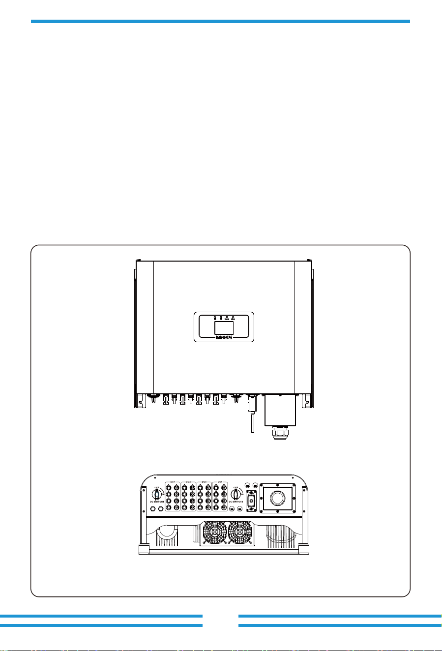
On-grid inverter can convert solar panel DC power into AC power which can directly input to
the grid. Its appearance is shown below.These models contain SUN-30K-G03, SUN-33K-G03,
SUN-35K-G03, SUN-40K-G03, SUN-45K-G03 and SUN-50K-G03.
The following is collec�vely referred to as “inverter”.
lim iter1 lim iter2
RS4 85-1 RS48 5-2
RS2 32/48 5
1.1 Appearance Introduc�on
1. Introduc�on
Pic 1.1 Front view
Pic 1.2 Bo�om view
About This Manual
The manual mainly describes the product informa�on, guidelines for installa�on, opera�on and
maintenance. The manual cannot include complete informa�on about the photovoltaic (PV) system.
How to Use This Manual
Read the manual and other related documents before performing any opera�on on the inverter.
Documents must be stored carefully and be available at all �mes. Contents may be periodically
updated or revised due to product development. The informa�on in this manual is subject to
change without no�ce. The latest manual can be acquired via [email protected]
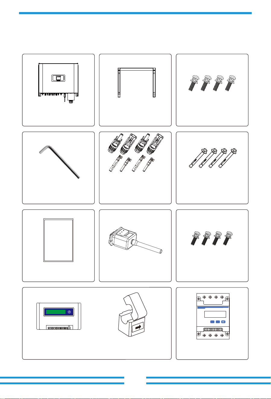
1.2 Parts list
- 02 -
Please check the following table, to see whether all the parts are included in the package:
Wall moun�ng bracket x 1
Moun�ng stainless steel
screws M4×12
x 4
Grid-�ed PV String Inverter
x 1
DC power connectors
(including Inserted spring)
30Kw, 33Kw, 35Kw x 8 pairs
40Kw, 45kw x 9 pairs
50Kw x 12 pairs
Stainless steel an�-collision
bolt M6×80
x 4
Wrench x 1
User
manual
User manual x 1
Installa�on screws M5× 12
x 8
Meter(op�onal)
x 1
Datalogger (op�onal) x 1
Three-Phase Smart Meter
SET ESC
SUN limiter(op�onal) x 1
When ordering the sun limiter, it will includes 3pcs CT.
*Sensor Clamp x 3
- 19 - - 20 -
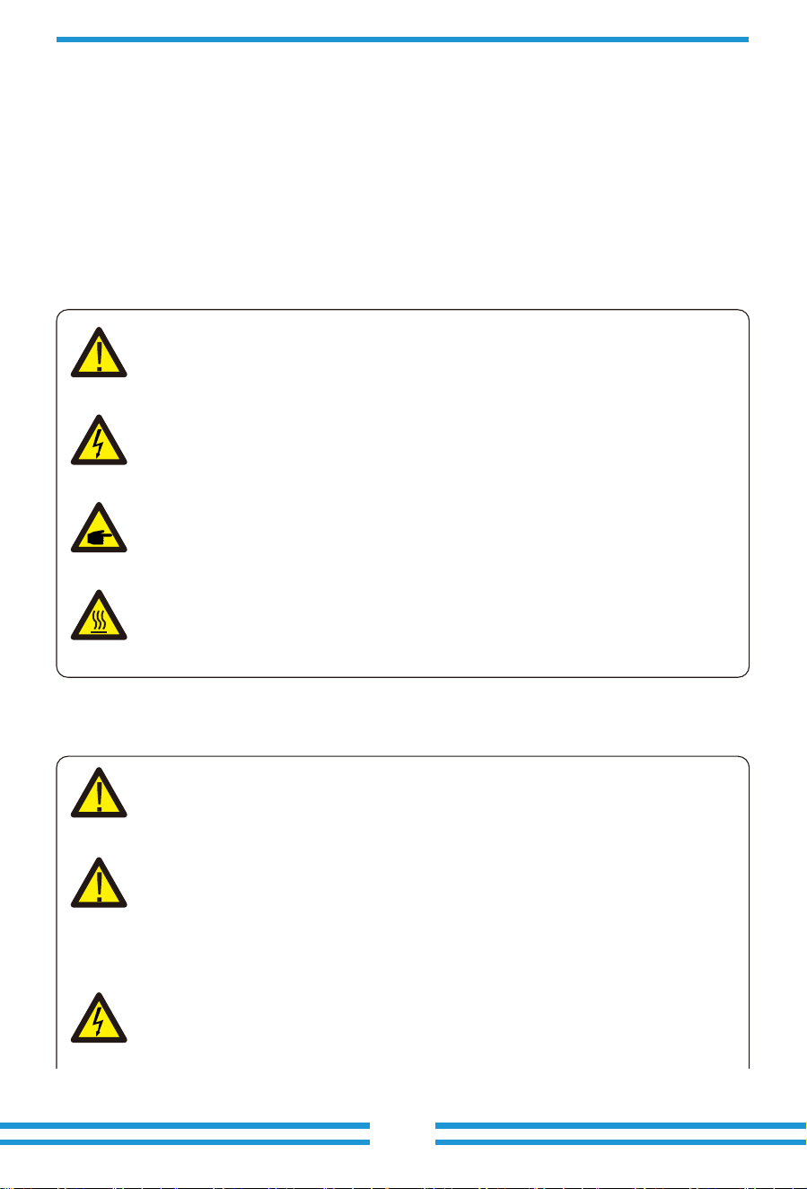
2. Safety warnings and instruc�ons
2.1 Safety signs
2.2 Safety instruc�ons
- 03 -
Improper use may result in poten�al electric shock hazards or burns. This manual contains
important instruc�ons that should be followed during installa�on and maintenance. Please
read these instruc�ons carefully before use and keep them for future reference.
Safety symbols used in this manual, which highlight poten�al safety risks and important safety
informa�on, are listed as follows:
Shock Hazard:
Cau�on, risk of electric shock symbol indicates important safety instruc�ons,
which if not correctly followed, could result in electric shock.
High Temperature Hazard:
Cau�on, hot surface symbol indicates safety instruc�ons, which if not correctly
followed, could result in burns.
Safety Hint:
Note symbol indicates important safety instruc�ons, which if not correctly
followed, could result in some damage or the destruc�on of the inverter.
Warning:
Warning symbol indicates important safety instruc�ons, which if not correctly
followed, could result in serious injury or death.
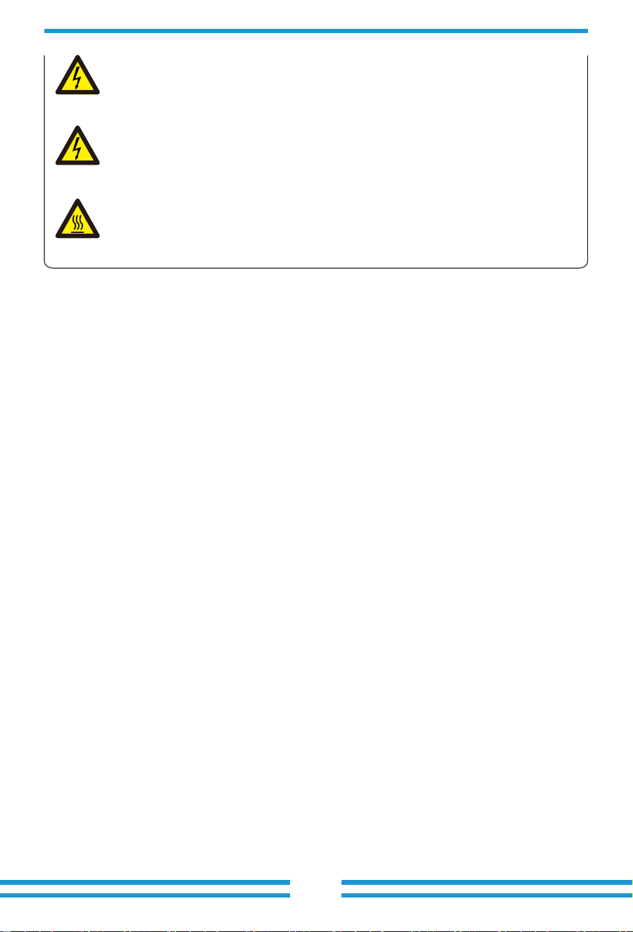
Shock Hazard:
Prohibit disassembling inverter case, there exis�ng shock hazard,which may
cause serious injury or death, please ask qualified person to repair.
Warning:
Electrical installa�on of the inverter must conform to the safety opera�on rules
of the country or local area.
Warning:
Inverter adopts non-isolated topology structure, hence must insure DC input and
AC output are electrical isolated before opera�ng the inverter.
Strictly prohibit grounding the posi�ve and nega�ve poles of the PV string.
Otherwise it will damage the inverter.
- 04 -
2.3 Notes for using
The three phase string power inverter is designed and tested under related safety regula�ons.
It can ensure the personal safety of the user. But as a electric device, it may cause shock or
injury by incorrect opera�on. Please operate the unit under below requirements:
1. Inverter should be installed and maintained by qualified person under local standard
regula�ons.
2. Must disconnect the AC side first, then disconnect DC side while doing installa�on and
maintenance, a�er that, please wait at least 5 mins to avoid ge�ng shocked.
3. Local temperature of the inverter may exceed 60 ℃ while under opera�ng.Do not touch
to avoid ge�ng injured.
4. All electrical installa�on must be in accordance with local electrical standards, and
achieved permission of local power company.
5. Please take appropriate an�-sta�c measure.
6. Please install where children can not touch.
Shock Hazard:
When PV module is exposed to sunlight, the output will generate DC voltage.
Prohibit touching to avoid shock hazard.
Shock Hazard:
While disconnect the input and output of the inverter for maintenance, please
waits for at least 5 mins un�l the inverter discharge the remnant electricity.
High Temperature Hazard:
Local temperature of inverter may exceed 80℃ while under opera�ng.
Please do not touch the inverter case.
- 05 -
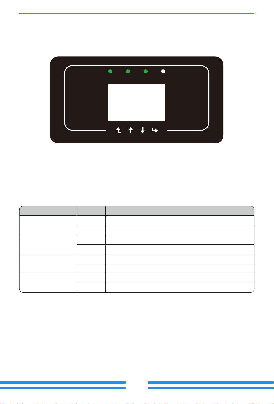
3.2 Status Indicator
3. Opera�on Interface
Pic 3.1 Front panel display
3.1 Interface View
There are four LED status indicator lights in the front panel of the inverter. Please see table 3.1
for details.
Explanaon
Inverter detects DC input
Low DC input voltage
Grid Connected
Grid Unavailable
Under normal opera�ng
Stop opera�ng
Detected faults or report faults
Under normal opera�ng
Indicator status
●DC
●AC
●NORMAL
● ALARM
on
off
on
off
on
off
on
off
Table 3.1 Status indicator lights
ACDC
AlarmNormal
3.3 Bu�ons
3.4 LCD Display
- 06 -
There are four bu�ons on the inverter panel: Above is Up and increase bu�on(UP), Below
is down and decrease bu�on(DOWN), Le� is ESC bu�on(ESC), Right is Enter bu�on(ENTER).
Achieving below func�ons by the four bu�ons:
● Page turning (use UP and DOWN bu�on);
●Modify adjustable parameters (use ESC and ENTER bu�on).
Three phase string inverter use 256*128 dot forma�on display, Display below content:
● Inverter opera�on status and informa�on;
● Opera�ng informa�on
● Warning message and malfunc�on display.
Esc Up Down Enter
4.1 Select installa�on loca�on
4. Product installa�on
- 07 -
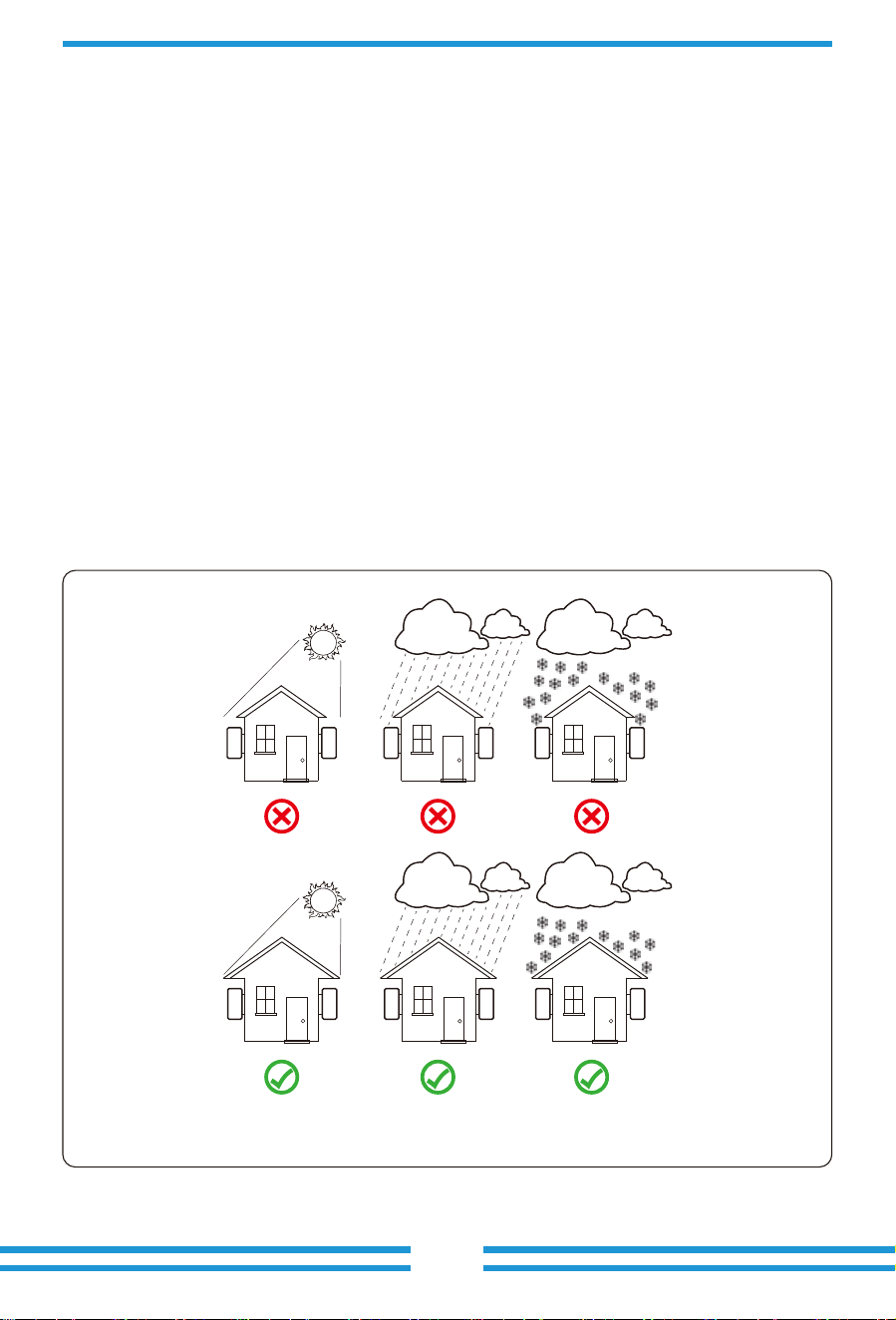
To select a loca�on for the inverter, the following criteria should be considered:
WARNING: Risk of fire
● Do not install the inverter in areas containing highly flammable materials or gases.
● Do not install the inverter in poten�ally explosive atmospheres.
● Do not install in small closed spaces where air can not circulate freely. To avoid overhea�ng,
always make sure the flow of air around the inverter is not blocked.
● Exposure to direct sunlight will increase the opera�onal temperature of the inverter and
may cause output power limi�ng. It is recommended that inverter installed to avoid direct
sunlight or raining.
● To avoid overhea�ng ambient air temperature must be considered when choosing the
inverter installa�on loca�on. It is recommended that using a sun shade minimizing direct
sunlight when the ambient air temperature around the unit exceeds 100°F/40℃.
Pic 4.1 Recommended installa�on place
- 08 -
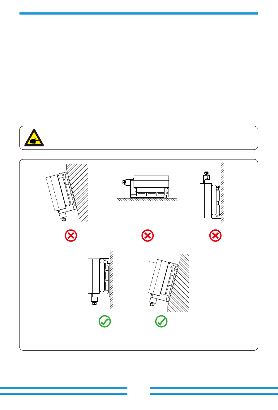
● Install on a wall or strong structure capable of bearing the weight.
● Install ver�cally with a maximum incline of +/-15°. If the mounted inverter is �lted to an
angle greater than the maximum noted, heat dissipa�on can be inhibited, and may result in
less than expected output power.
● If install more than one inverter, must leave at least 500mm gap between each inverter. And
each inverter must be at least 500mm above and below.And must install the inverter at the
place where children cannot touch. Please see picture 4.3.
● Consider whether the installa�on environment is helpful to see the inverter LCD display and
indicator status clearly.
● Must offer a ven�late environment if inverter installed in the air�ght house.
Safety Hint:
Do not place or store any items next to the inverter.
Pic 4.2 Installa�on Angle
≤15°
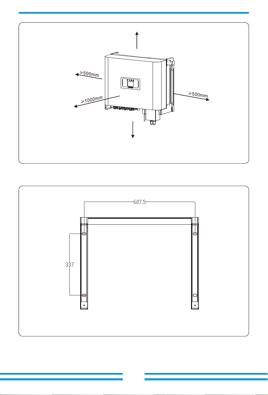
Pic 4.4 Mou�ng bracket dimensions
≥500mm
≥500mm
- 09 -
4.2 Inverter of inverter
Pic 4.3 Installa�on Gap
- 10 -
Anchoring
Mounting bracket
M12*80 Stainless steel screws
Inverter
Pic 4.5 Inverter Installa�on
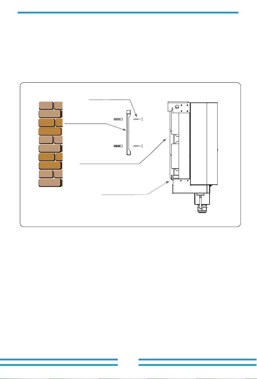
4.3 Inverter Installa�on
The inverter should be mounted in a ver�cal posi�on. The steps of moun�ng are as follows
1. For brick walls, the posi�on of the holes should be suitable for the expansion bolts.
2. Make sure the bracket is horizontal and the moun�ng holes are in the correct points. Drilling
the holes on the wall according the marks.
3. Using the expansion bolts to fix the bracket to the wall.
- 11 -
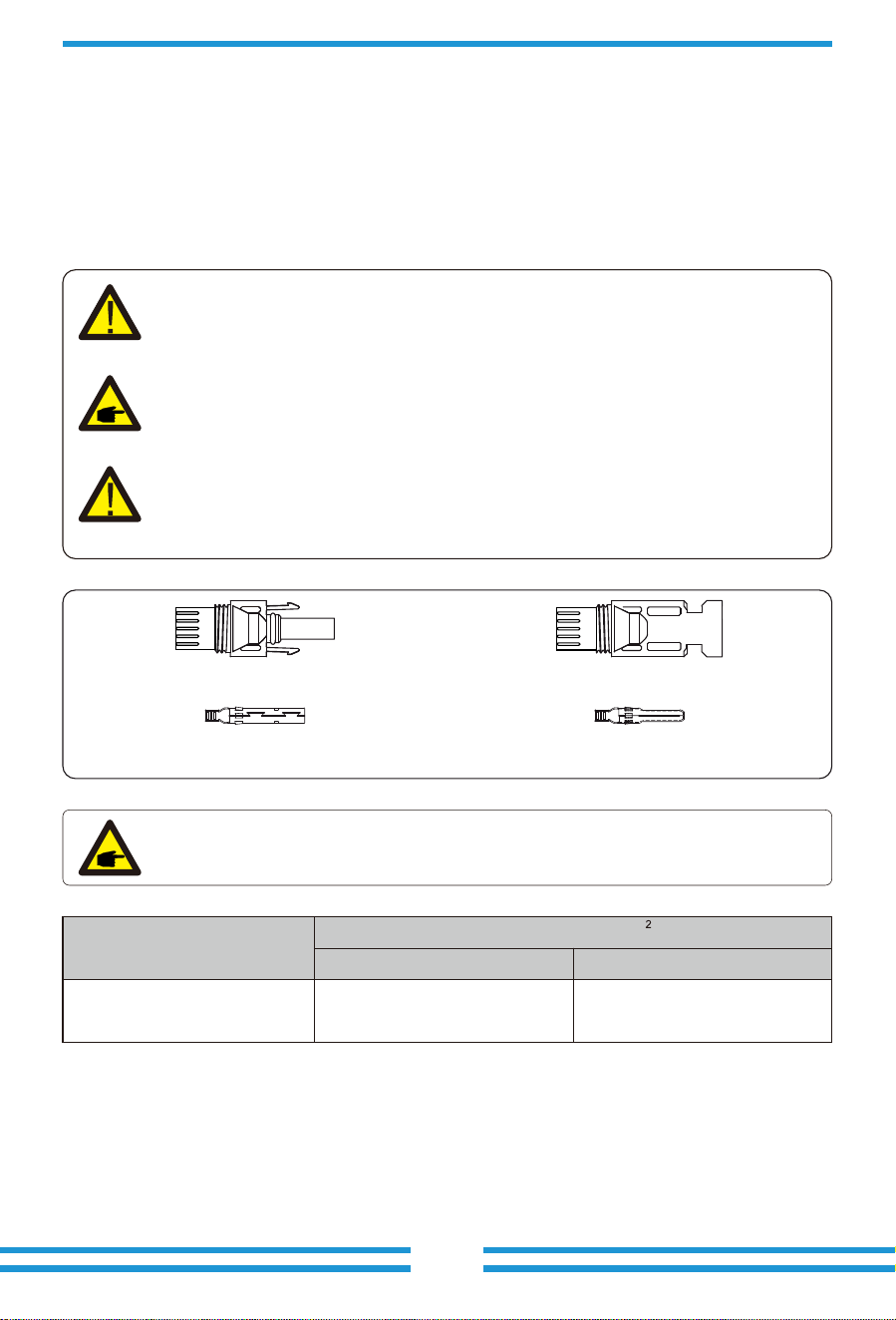
5.1 DC input terminal connec�on
5 Electrical Connec�on
Table 5.1 DC Cable Specifica�ons
1. Switch the Grid Supply Main Switch(AC)OFF.
2. Switch the DC lsolator OFF.
3. Assemble PV input connector to the inverter.
Safety Hint:
Please don’t connect PV array posi�ve or nega�ve pole to the ground, it could
cause serious damages to the inverter.
Safety Hint:
Before connec�ng inverter, please make sure the PV array open circuit voltage is
within the 1000V of the inverter.
Safety Hint:
Before connec�on, please make sure the polarity of the output voltage of PV
array matches the “DC+” and “DC-” symbols.
Safety Hint:
Please use approved DC cable for PV system.
Pic 5.1 DC+connector (MC4)
Pic 5.2 DC-connector (MC4)
Cable type
Range Recommended value
Cross secon(mm )
Industry generic PV cable
(model: PV1-F)
4.0~6.0
(12~10AWG)
4.0(12AWG)
- 12 -
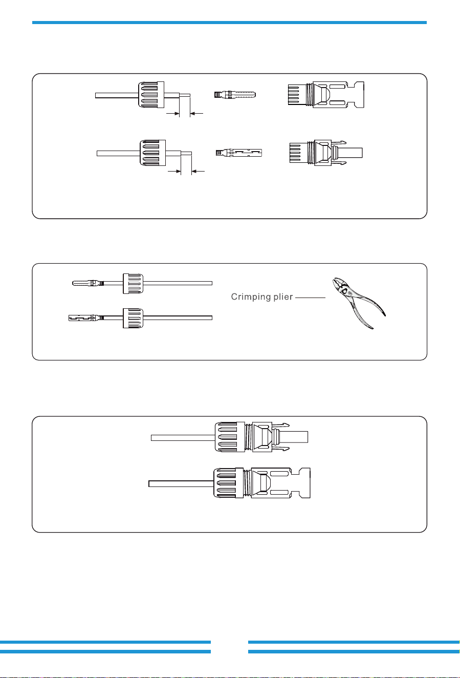
The steps to assemble the DC connectors are listed as follows:
a) Strip off the DC wire about 7mm, disassemble the connector cap nut (see picture 5.3).
b) Crimping metal terminals with crimping pliers as shown in picture 5.4.
c) Insert the contact pin to the top part of the connector and screw up the cap nut to the top
part of the connector. (as shown in picture 5.5).
Pic 5.3 Disassemble the connector cap nut
7mm
7mm
Pic 5.4 Crimp the contact pin to the wire
Pic 5.5 connector with cap nut screwed on
- 13 -
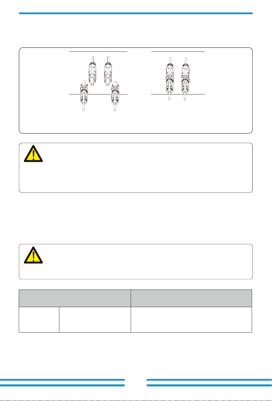
d) Finally insert the DC connector into the posi�ve and nega�ve input of the inverter, shown as
picture 5.6
Pic 5.6 DC input connec�on
Warning:
Sunlight shines on the panel will generate voltage, high voltage in series may
cause danger to life. Therefore, before connec�ng the DC input line, the solar
panel needs to be blocked by the opaque material and the DC switch should
be 'OFF', otherwise, the high voltage of the inverter may lead to life-
threatening condi�ons.
Table 5.2 Recommened cable specifica�ons
5.2 AC input terminal connec�on
AC connec�on can use 16-25mm, 105℃cable, please make sure the resistance of cable is
lower than 1.5ohm. If the cable is longer than 20m, it’s recommended to use 20-25mm cables.
Warning:
The AC cable line L1 is connected to socket 1; L2 is connected to socket 2; L3 is
connected to socket 3, the PE line is connected to the earth , the N wire is
connected to the socket of N.
Conductor
cross-sectional
area(mm )
Recommended range
Cable specifications
Copper core cable
10-25
2
AC wire produc�on method is the same as that of 5.2.1.
AC wire installa�on method:
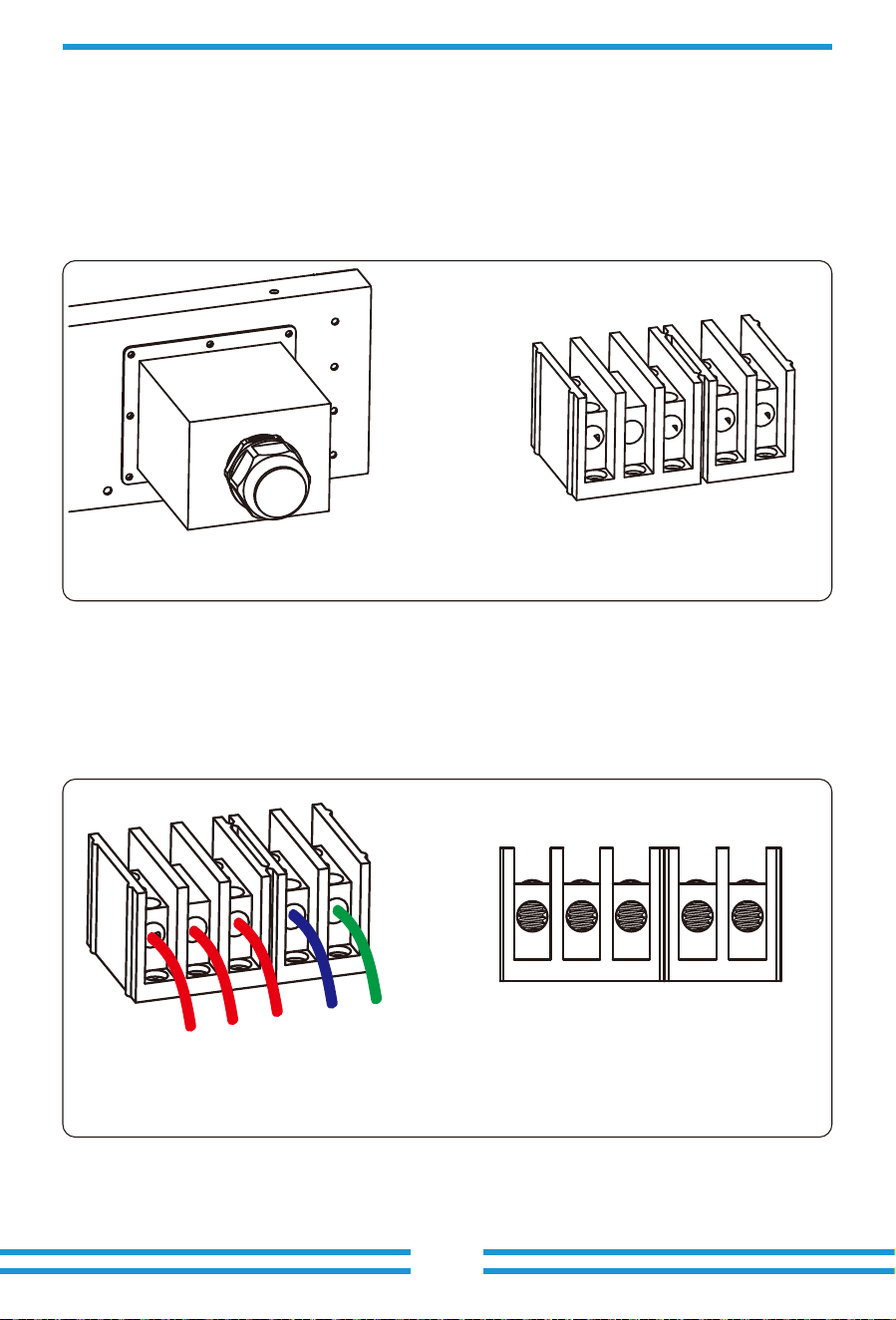
1) Remove the 8 fixing screws on the AC junc�on box of the inverter as shown in Pic 5.7.
A�er removing the junc�on box, you can see the terminals of the inverter. The default is 5
digits as shown in Pic 5.8.
2) Connect the cable through the junc�on box, waterproof jacket, and insert into the terminal
(The picture shows the connec�on mode of three phase lines connected to the junc�on box,
ground wire screwed on the inverter shell) Pic5.9,and use hexagon screwdriver to presses the
wiring harness to the connect terminal as shown in Pic5.10.
Pic 5.7 AC junc�on box Pic 5.8 AC terminal
- 14 -
Pic 5.9 AC cable connected t
o the terminal
Pic 5.10 Tightening the
AC connec�on cable
L1
L2
L3
N
PE
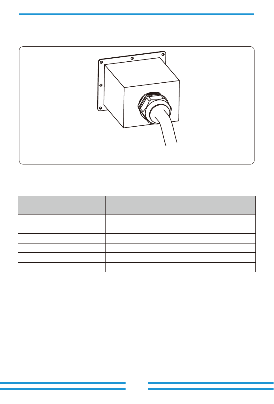
3) Screw the AC connec�on cover back to the shell and �ghten all the screws to �ghten the
waterproof protec�on connector, as shown in Pic 5.11
5.2.3 Recommended current protector specifica�ons
Pic 5.11 Tighten the AC junc�on box
Table 5.3 Recommended current protector specifica�ons
Inverter
SUN-30K-G03
SUN-33K-G03
SUN-35K-G03
SUN-40K-G03
SUN-45K-G03
Rated voltage
400
400
400
400
400
Rated output power(KW)
30
33
35
40
45
Current protection device(A)
60
70
80
80
SUN-50K-G03 400 50 100
80
- 15 -
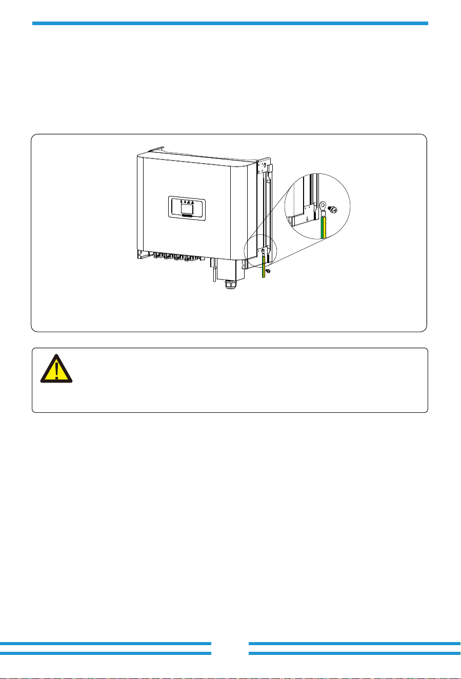
Good grounded is important for resist the surge voltage shock and improve EMI's performance.
So before the connec�on of AC, DC, communica�on connec�ons, inverter needs to ground first.
For a single system, just ground the PE cable; For mul�ple machine systems, all PE cables of the
inverter need to be connected to the same grounding copper platoon to ensure the equipotent
connec�on. The installa�on of the shell ground wire is shown as.
5.3 Connec�on of the ground line
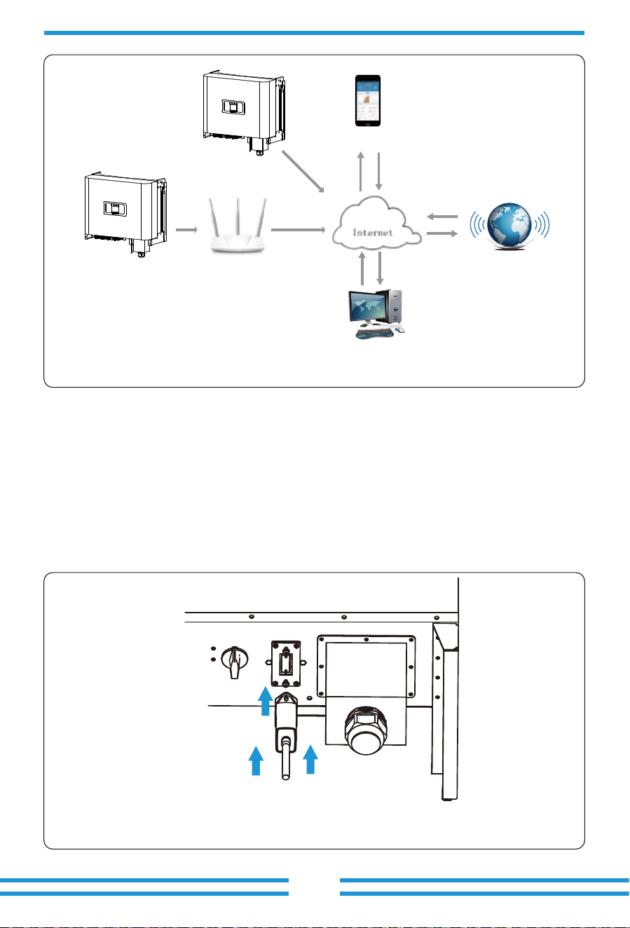
Inverter has the func�on of wireless remote monitoring inverter. The inverter has Wifi func�on
and Wifi Plug in the accessories is used to realize the connec�on between the inverter and the
network. The opera�on, installa�on, networking, APP download are detailed in the WIFI PLUG
instruc�ons. Figure 5.13 is the Internet monitoring solu�on.
5.4 Inverter monitoring connec�on
5.12 The installa�on of the shell ground wire
- 16 -
Warning:
Inverter has built-in leakage current detec�on circuit, If an external leakage
current protec�on device is connected, its opera�ng current must be greater
than 300 mA or higher, otherwise inverter may not work properly.
When the inverter is out of the factory, the loca�on of the installa�on of datalogger is sealed by a
sealed plate as shown in Picture 5.14. When installing the datalogger, remove the sealing plate,
replace it with the sealing plate with square hole in the accessories, and �ghten the screws. Insert
the datalogger into the interface and fix it with a screw. The configura�on of the datalogger needs
to be performed a�er various electrical connec�ons have been completed and the inverter DC
power on. When the inverter is on the DC power, it is determined whether the datalogger is
normally electrified (The LED light shines out of the shell).
5.4.1 Installa�on of datalogger
Pic 5.13 Internet monitoring solu�on
Pic 5.14 datalogger installa�on diagram
Router
WIFI
GPRS
Web Server
Phone
- 17 -

Ensure that the inverter meets the following condi�ons before star�ng the inverter, otherwise
it may cause fire or damage to the inverter without quality assurance, at the same �me the
situa�on on our company does not undertake any responsibility. At the same �me, to op�mize
the system configura�on, it is recommended that the two inputs be connected to the same
number of PV modules.
a). The maximum open voltage of each set of PV modules shall not exceed 1000Vdc under any
condi�ons.
b). Each input of the inverter be�er use the same type of PV module in series.
c). Total output power of pv shall not exceed the maximum input power of inverter, each PV
modules shall not exceed the rated power of each channel.
When start up the inverter, should fellow below steps:
1. First switch on the AC breaker.
2. Turn on the DC switch of the PV module, and if the panel provides sufficient star�ng voltage
and power, the inverter will start.
3. When the AC voltage and DC voltage are normal, the inverter start-up is ready to begin. The
inverter will first check the internal parameters and the grid parameters, while the liquid
crystal will show that the inverter is self-checking.
4. If the parameter is within acceptable range, the inverter will generate energy.
NORMAL indicator light is on.
6. Start up and Shut off
6.1 Start up the inverter
Must follow below steps while Shu�ng down the inverter:
1. Switch off the AC breaker.
2. Wait for 30 seconds, turn off the dc switch (if any), or simply disconnect the dc input
connector. The inverter will close the LCD and all led within two minutes.
6.2 Shut off the inverter
For the configura�on of datalogger, please refer to illustra�ons of the datalogger.
5.4.2 Configura�on of datalogger
- 18 -
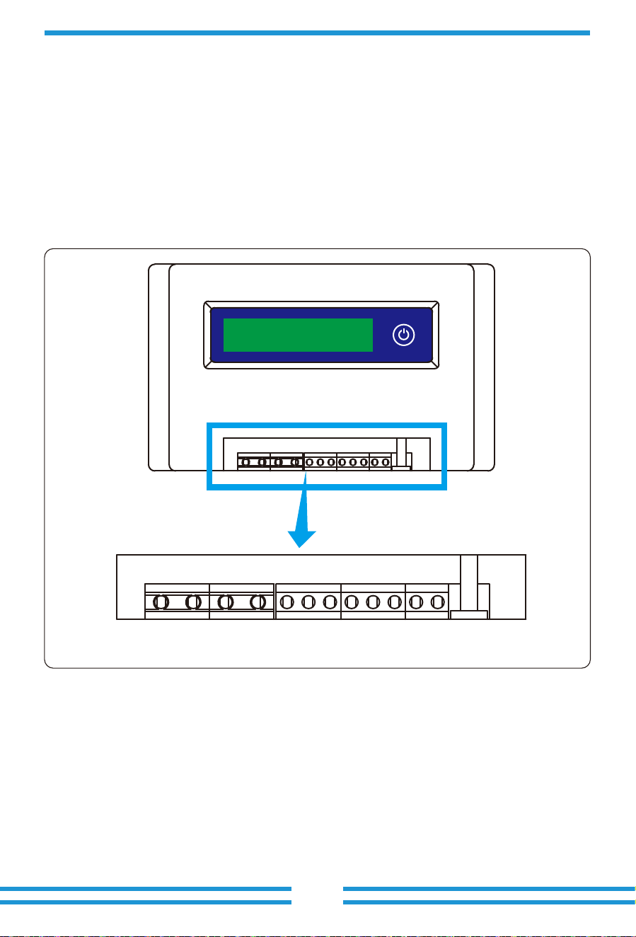
The inverter has external zero export func�on. This func�on is op�onal. It can collect counter-
current power to control the output power of the inverter, so that the power of inverter and
load can be offset, and the excess power will not be fed back to the grid. If you purchase the
inverter with zero export func�on, an external zero export device ( SUN limiter or energy meter)
will be included in the package which is necessary for the func�on. The SUN limiter shows as
Pic 7.1. You can see corresponding line mark next to the green interface. The green terminals
on the le� are the interface of three-phase AC line (L1, L2, L3) and N Line (N), and the the right
are the interface between three sets of current sensor and one set of control terminals. SUN limiter
will collect voltage and current from these interfaces and send control signals to the inverter.
L1 L1(L)L1(K)L2(L)L2(K)L3(L)L3(K) + -L2 L3 N
- 19 - - 20 -
- 19 -
7 Zero export func�on via SUN limiter
7.1 SUN Limiter func�on wiring diagram
Pic 7.1 SUN Limiter view
When you are reading this, we believe that you have completed the connec�on according to the
requirements of chapter 5, if you has been running your inverter , and you want to use the limiter
func�on, please turn off AC and DC switch of the inverter, and wait for 5 minutes un�l the inverter
completely discharged.In order to make it easier for you to use the limiter func�on, we have
specifically given the wiring diagram, as shown in Picture 7.2, the yellow/green/red live line
(L1,L2,L3) connected to the u�lity grid live line (U/V/W), blue line means the neutral line.
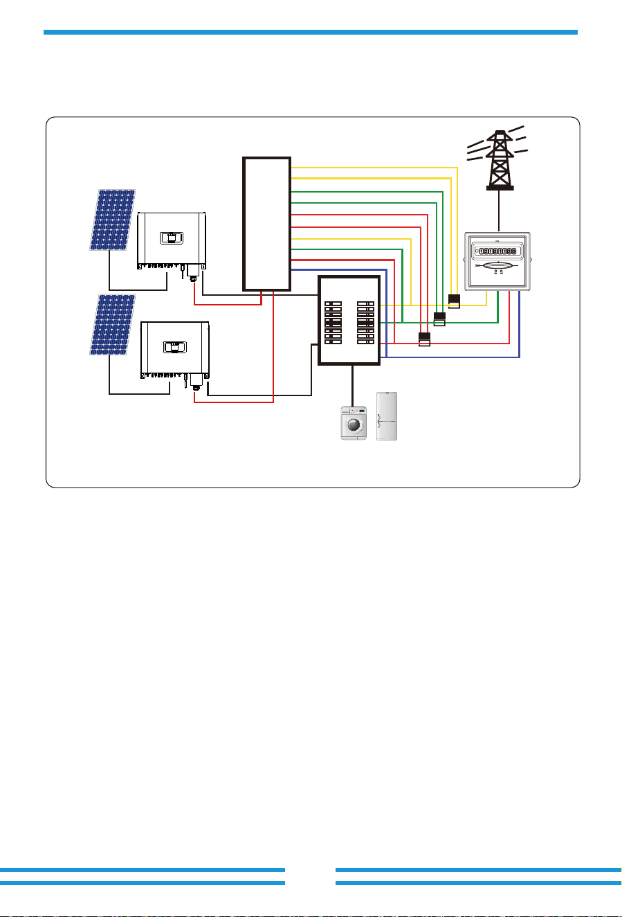
We recommend installing an AC switch between the inverter outlet and the u�lity grid, the specs
of the AC switchis determined by the load capacity. The AC switch we recommend to connect to
the inverter output refer to Table 5.2.
U
V
L1(L)
Solar panels
Load
Distribution Box
Limiter
Control signal
L1(K)
L2(L)
L2(K)
L3(L)
L3(K)
L1
L2
L3
N
W
N
Control signal
- 20 -
7.2 Connect the SUN limiter to inverter
The SUN limiter will measure the voltage and current of three phases separately, and this manual
only introduces the installa�on steps of one phase, the other two phases are the same. The specific
installa�on steps are as follows:
Pic 7.2 Wiring diagram
(1) Connect SUN limiter to the grid. Connected to the grid is to measure the voltage of grid. Before
connect to the grid, please turn off the switch to avoid the risk of electric shock. Choose one wire
from the bo�om of the three-phase DC switch. (any phase of U,V,W) to connect with L1 terminal,
then �ghten the line with a screwdriver.
(2) Connect SUN limiter to clamp senor. Clamp senor can measure the current of the AC side, it
should be connected to the front side of the load (domes�c appliance ect.) to achieve this func�on.
Only when the SUN limiter collects the voltage and current of the same phase can it judge the
power of the phase. So the clamp senor should be connected to the same phase as the before.
Open the side buckle of the clamp senor, then clamp the senor to the AC line on the DC switch,
the arrow direc�on on the senor should towards that of the load. The clamp senor has two lines
(shown as below), and the white line corresponds to K terminal, black line corresponds to L
terminal. Connect the white line to the L1(L) and L1(K) terminal refer to the line mark of the SUN
limiter and �ghten the line with screwdriver. This is the whole installa�on process of one phase.
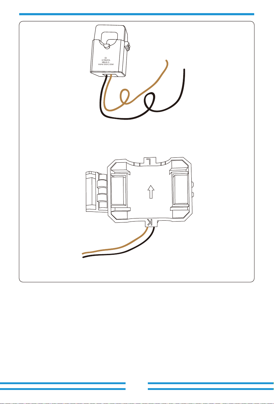
Pic 7.4 Clamp Sensor internal arrow
Pic 7.3 Clamp Sensor
L
K
- 21 -
(3) A�er you finish the installa�on in process 1 and 2, connect the N line (N) to the N terminal
of the limiter and �ghten the line.
(4) Connect the control line. There are two numbers 1 and 2 on the interface of SUN limiter, and
the same on the waterproof terminal of the inverter. Twist the waterproof terminal and connect
the red line to number 1 and black line to number 2 shown as the picture. A�er that connect
the terminal to the interface of the SUN limiter. The other side of the line should be connected to
the control terminal.
Load
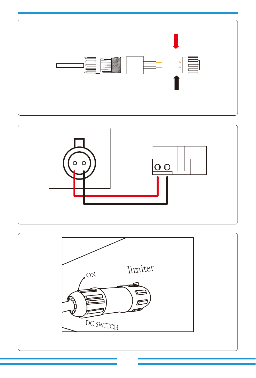
Pic 7.5 Waterproof terminal
Pic 7.6 Connect SUN limiter to inverter
Pic 7.7 Connect terminal to inverter
1 2
limiter
+ -
1
2
- 22 -
- 23 -
Press the bu�on of the SUN limiter to the se�ng interface. Long press the bu�on to switch the
an�-backflow mode. SUN limiter has two an�-backfolw modes, the minimum mode and the average
mode. In the minimum mode, SUN limiter will control the power of the inverter according to the
phase with the lowest power to ensure that no reverse current will occur in each phase. In average
mode, SUN limiter controls the output of the inverter according to the average of the total power
of the three-phase load, which may cause single backflow. The controller is produced in the
minimum mode to ensure no an�-backflow happens to the customers.
Pic 7.8 Zero-export func�on via SUN limiter se�ng interface
7.3 Debugging SUN Limiter
Turn on the an�-backflow func�on of the inverter refer to the manual , then turn on the SUN
limiter's power supply, next close the DC switch, and last turn on the inverter.
MENU》Setup》Run Param
OK Cancel
ActiveP 100%
ReactiveP 0.0%
PF 1.000
Fun_ISO OFF
Fun_RCD OFF
SelfCheck 10S
Island OFF
Meter OFF
Limiter ON
E_Coef 0.00
Meter_CT 0
MPPT Num 3
- 19 -
- 24 -
7.4 Zero-export func�on (Op�on)
7.4.1 Zero-export func�on via energy meter
The string inverter supports zero-export func�on via Energy meter / SUN-Limiter. Based on
con�nuously data communica�on, once the Limiter or energy meter detects power export to
the grid, it will send the informa�on to the inverter and then inverter can instruct the inverter
to ramp down its ac�ve power according to match the load demand and achieve zero export.
The Zero-export func�on is op�onal. If you buy the inverter with zero-export func�on via
energy meter, energy meter will be included in the package which is necessary for zero-export
func�on.
When you are reading this, we believe that you have completed the connec�on according to
the requirements of chapter 5, if you have been running your inverter at this �me, and you
want to use the zero-export func�on, please turn off AC and DC switch of the inverter, and
wait for 5 minutes un�l the inverter completely discharged. Please follow below Picture 7.9 to
connect the energy meter.
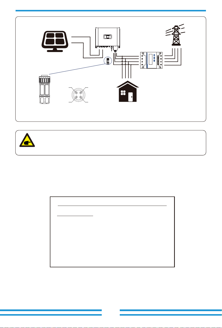
For system wiring diagram, the red line refers to L line (L1, L2, L3), the black line refers to the
neutral line (N). Connec�ng energy meter RS485 cable to inverter's RS485 port. It's recom-
mended to install an AC switch between the inverter and the u�lity grid, the specs of the AC
switch are determined by the power of load.
If there is no integrated DC switch inside the inverter you purchased, we commend you to
connect the DC switch. The voltage and current of the switch depend on the PV array you
access.
Pic 7.9 CHINT meter
Three-Phase Smart Meter
SET ESC
1 74 10
2524
3 96 10
RS 485
CHNT DTSU666
- 25 -
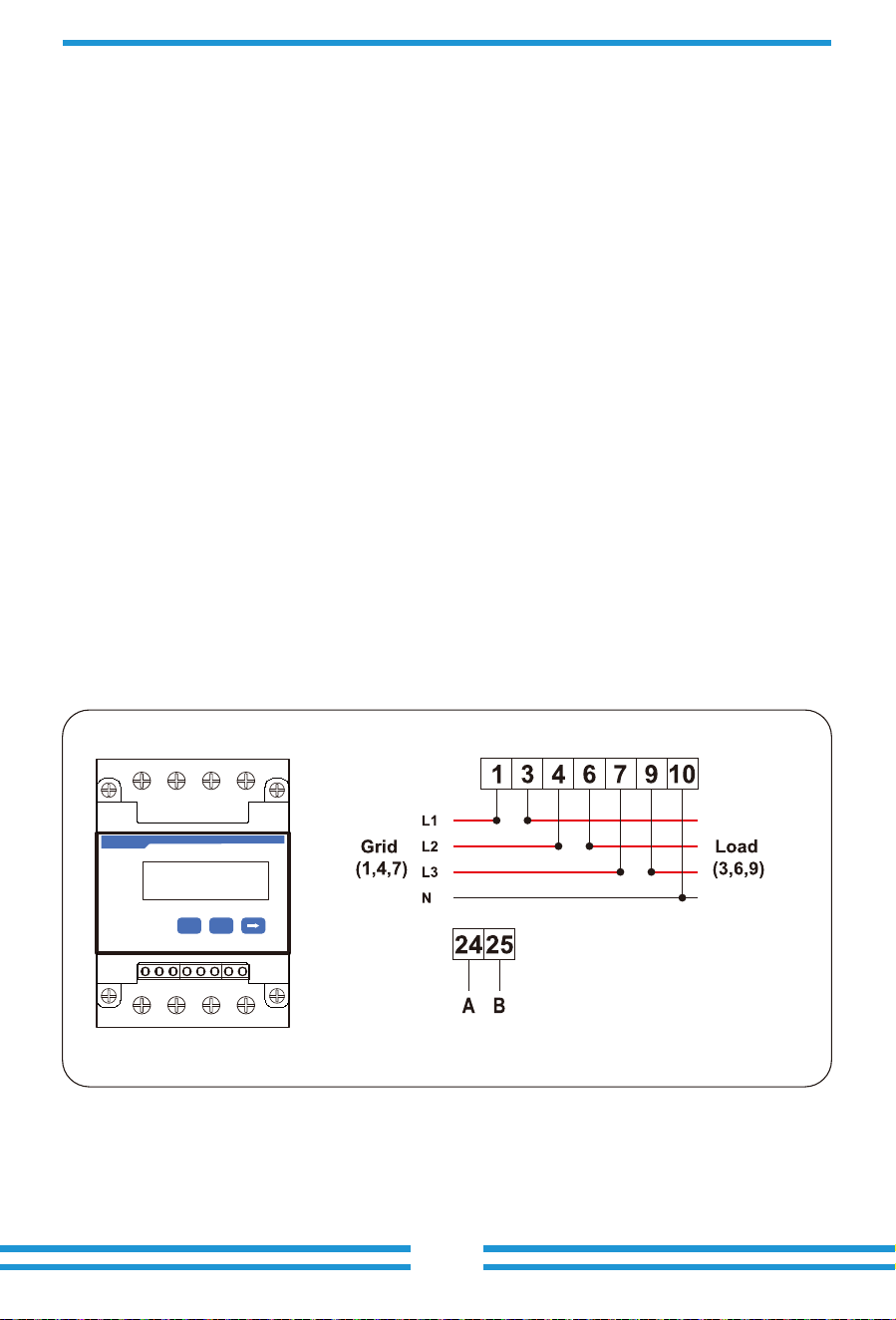
Warning:
Ensuring grid input cables connect 1/4/7/10 port of energy meter, and inverter
AC output cables connect 3/6/9/10 port of energy meter when connec�ng.
1 74 10
2524
3 96 10
Pic 7.10 Connec�on diagram of CHINT meter
Solar Panel array
Inverter
meter
Grid
RS485 Communication
1
2VCC_5V 485_A
485_BGND
3
4
Family load
Three-Phase Smart Meter
SET ESC
L1
L2
L3
N
L1
L2
L3
N
Pic 7.8 Zero-export func�on via energy meter
7.4.2 Debugging energy meter
Turn on the an�-backflow func�on of the inverter refer to the manual, next close the DC switch,
and last turn on the inverter.
MENU》Setup》Run Param
OK Cancel
ActiveP 100%
ReactiveP 0.0%
PF 1.000
Fun_ISO OFF
Fun_RCD OFF
SelfCheck 10S
Island OFF
Meter ON
Limiter OFF
E_Coef 0.00
Meter_CT 0
MPPT Num 3
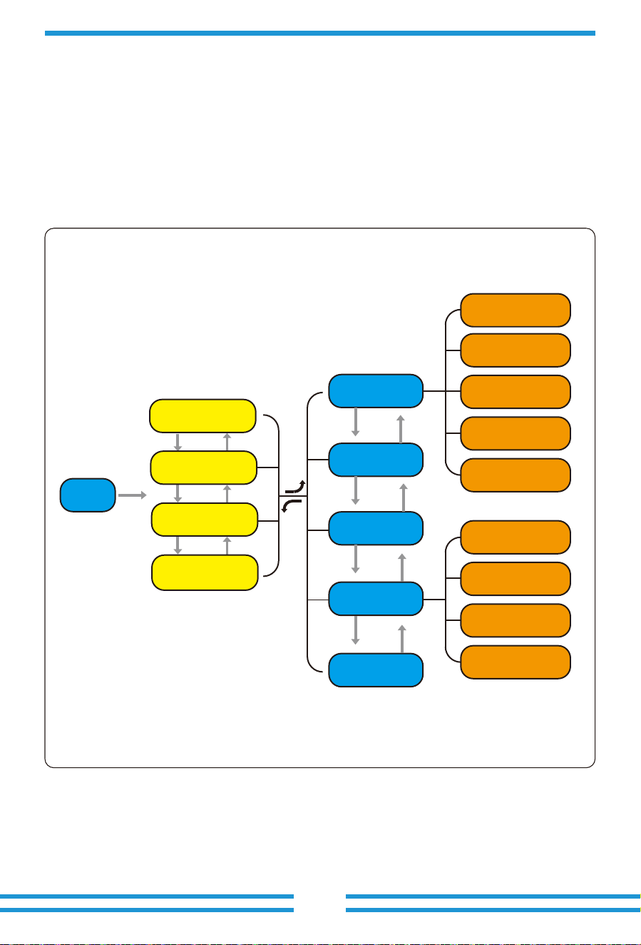
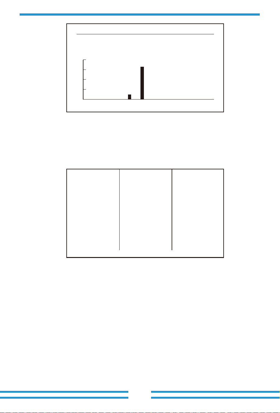
During normal opera�on, the LCD shows the current status of the inverter, including the
current power, total genera�on, a bar chart of power opera�on and inverter ID, etc. Press
the Up key and the Down key to see the current DC voltage, DC current, AC voltage, AC
current, inverter radiator temperature, so�ware version number and Wifi connec�on state
of the inverter.
8. General Opera�on
- 26 -
System param
Running param
Protection param
Comm param
E-Month
E-Day
E-Year
E-History
Test Data
Start
Statistics
Fault Record
ON/OFF
Setup
PV
LCD main menu
AC output data
Interface
DC input data
Pic 8.1 LCD opera�on flow chart
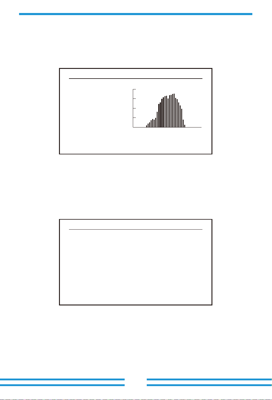
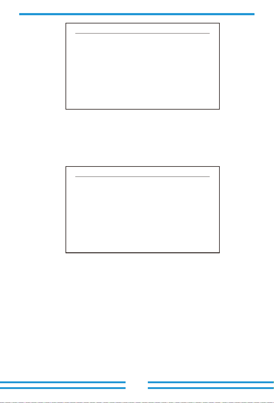
From the ini�al interface, you can check power, day power, total power, invertert ID , model
and �me.
8.1 The ini�al interface
Pic 8.1 The ini�al interface
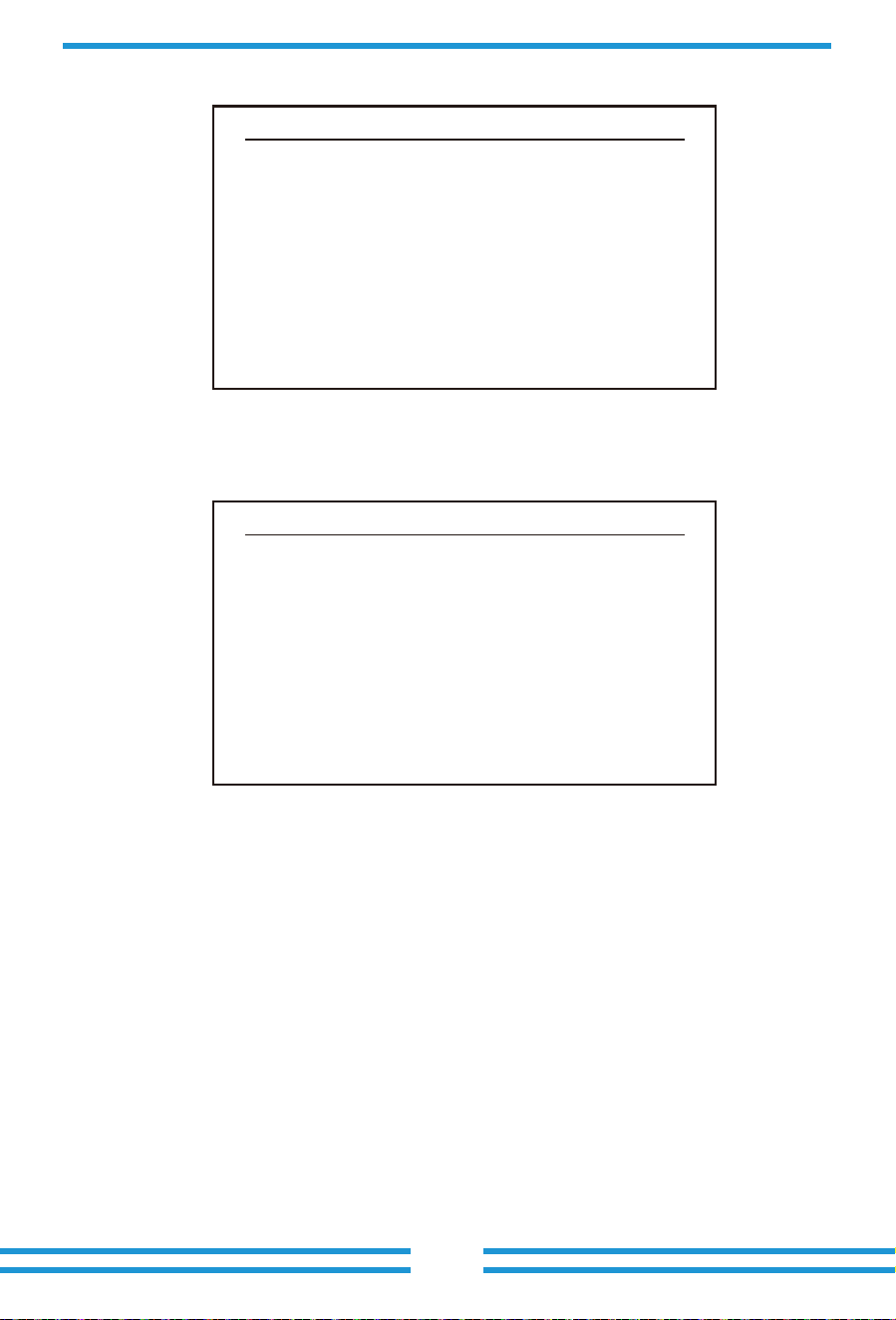
Pic 8.2 PV input and DC current informa�on
Press UP or Down you can check inverter DC voltage, DC current, AC voltage, AC current, inverter
temperature, so�ware version informa�on.
You can check the PV informa�on, the number of strings input, MPPT voltage and MPPT current.
Power:
Day :
Total :
State :
Standby 0
29.86Kw P - 45 Kw
295kWh
25 MWh
6 12 18 24
ID:1601012001
0.0Kw SN-01 2019-05-11 08:00:00
- 27 -
PV1 V : 0.0V I : 0.0A
RUN Input
- 28 -
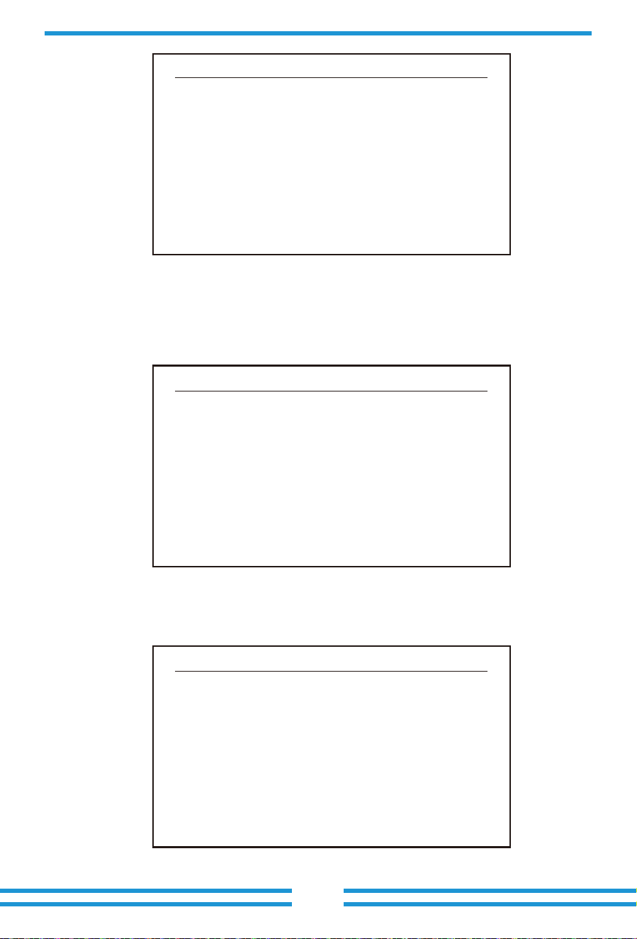
Pic 8.3 AC running state informa�on
You can check the three phase voltage, current, and grid frequency.
You can check the inverter LCD so�ware Ver0166 and Control So�ware Version Ver1860.
There are two black spot in the bo�om right corner. The first flash means inverter is
communica�ng with LCD. The second flash means LCD is communica�ng with wifi plug.
Ua : 234.5V Ia : 0.0A
Grid Freq : 50.00Hz
RUN Grid
Pic 8.4 Inverter firmware version
Pic 8.5 Meter power and load power
Ver : 0166
Ver : 1860
RUN
Meter Power: 0W
Load Power: 0W
Day Total
ImpEp : 0.00kWh 0.00kWh
ExpEp : 0.00kWh 0.00kWh
LoadEp : 0.00kWh 0.00kWh
PARAMETR Meter
SN: 0
There are four submenu in the Main Menu.
8.1.1 Main Menu
8.2 Sta�s�cs informa�on
Pic 8.5 Main Menu
Pic 8.6 Sta�s�cs
There are five submenu in the sta�s�cs.
Into each submenu through cursor.
E-Day E-History
E-Month
E-Year
Test Data 《
MENU》Statistics
- 29 -
Statistics 《
Fault Record
ON/OFF
Setup
PV VA
MENU
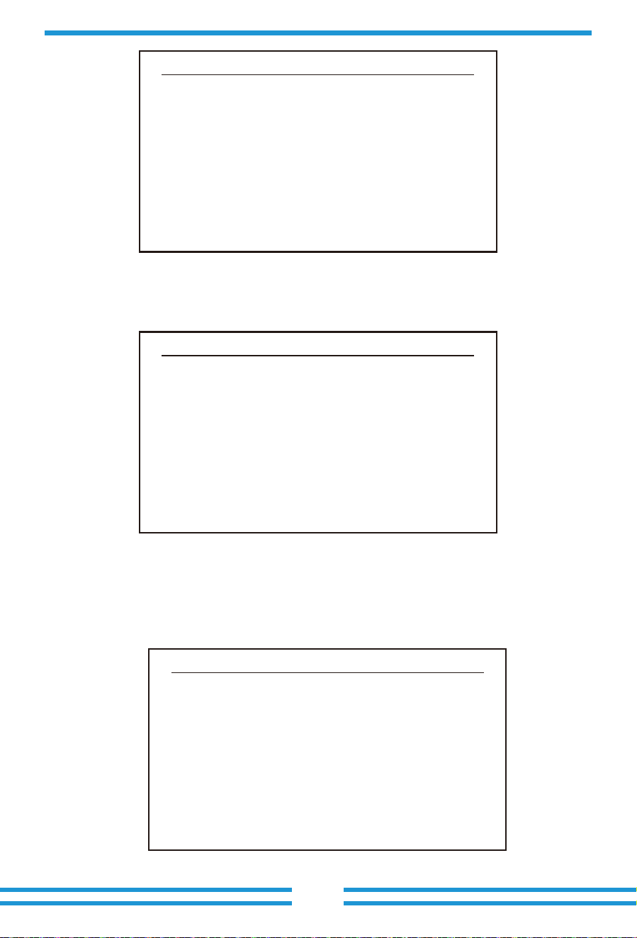
Pic 8.7 E-Day
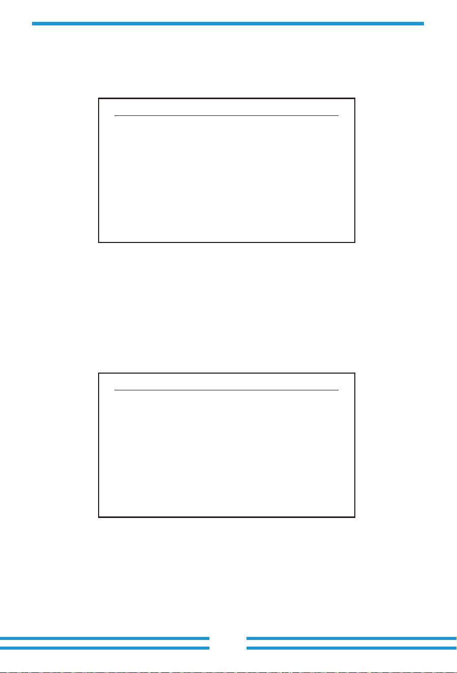
Pic 8.8 E-Month
Pic 8.9 E-Year
2019-04 1-10 20 31 <>
MENU》Statistics》E-Month
01
10MWh
02 03 04 05 06 07 08 09 10
<2019>
MENU》Statistics》E-Year
01
200KWh
02 03 04 05 06 07 08 09 10 11 12
<2019-05-11>
MENU》Statistics》E-Day
0
10MWh
6 12 18 24
- 30 -
8.3 Fault Record
This informa�on is for technician’s reference.
Only can keep four fault record in the menu include �me, customer can deal with it
depends on the error code.
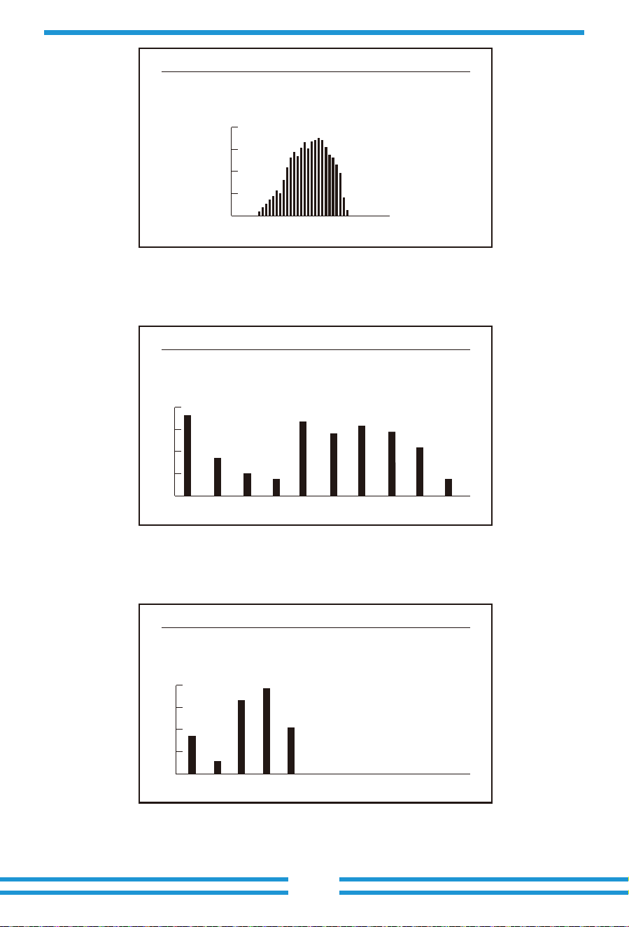
Pic 8.10 E-History
Pic 8.11Test Data
PV1
PV2
HV
GFD
DiL
AVL
126
1k2
: 19186
: 19198
: 24362
: 9119
36:
: -2
: 287
: 6
1k3
1k4
1k5
1k6
vHV
BSn
ofA
ofB
: 11126
: 11140
: 16666
: 2927
ofC
138
139
140
: 2057
: 2248
137 : 2145
: 1497
: 0
: 24362
: 12218
: 2065
: 2653
<2015-2024>
MENU》Statistics》E-History
15
5KWh
16 17 18 19 20 21 22 23 24
- 31 -
8.4 ON/OFF se�ng
Pic 8.12 Fault Record
MENU》Fault Record
Fault : F352019-05-05 08:38
F352019-05-05 08:37
F352019-04-24 18:47
F352019-04-24 17:54
F352019-04-24 17:53
1
2
3
4
History :
Pic 8.13 ON/OFF se�ng
MENU》ON/OFF
Turn ON
Turn OFF 《
Into each submenu through cursor.
- 32 -
8.5 Parameter se�ng
Se�ng includes system param, run param, protect param, comm.. param. All of these
informa�on for maintenance reference.
Pic 8.14 ON set
MENU》ON/OFF》Turn ON
Turn ON
OK 《
Cancel
Pic 8.15 OFF set
MENU》ON/OFF》Turn OFF
Turn OFF
OK 《
Cancel
- 33 -
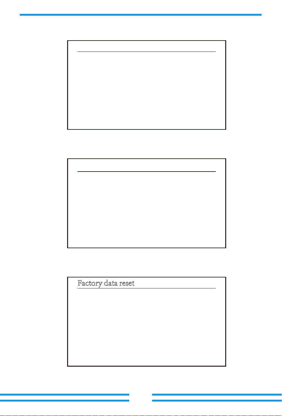
8.5.1 System Param
8.5.1.2 Time Set
System Param includes �me set, language set, display set and factory date reset.
Pic 8.16 Se�ng
MENU》Setup
System Param 《
Run Param
ParamProtect
ParamComm.
Pic 8.17 System Param
MENU》Setup》System Param
Time Set 《
Language Set
Display Set
Factory data reset
Pic 8.18 System Param
Time Set
2019-05-11 09:36:30
OK Cancel
- 34 -
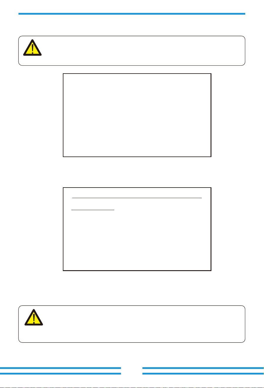
8.5.1.3 Language Set
8.5.1.4 Display Set
8.5.1.5 Factory data reset
Pic 8.19 Lauguage set
Pic 8.20 Display set
Pic 8.21 Factory data reset set
Display Set
Brightness Delay 《
Delay time 05S
OK Cancel
Factory data reset
Confirm to reset 《
Cancel
- 35 -
Lauguage Set
简体中文
English 《
Angielski
Pic 8.23 Running Param
Pic 8.22 Password
PassWord
* * * *
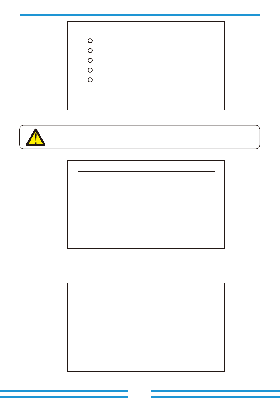
8.5.2 Running Param
- 36 -
Note:
Engineer Only.
We will set the param depends on the safety requirements, so customers don't
need to reset it. The password is same as 8.4 Running param
Note:
Password required-- only for access-authorized engineer. Un-authorized access
may avoid the warranty. The ini�al password is 1234.
MENU》Setup》Run Param
OK Cancel
ActiveP 100%
ReactiveP 0.0%
PF 1.000
Fun_ISO ON
Fun_RCD ON
SelfCheck 10S
Island ON
Meter OFF
Limiter OFF
E_Coef 0.00
Meter_CT 0
MPPT Num 3
8.5.4 Comm. Param
Pic 8.24 Protect Param
Pic 8.25 “CUSTOM”
Pic 8.26 Communica�on param
MENU》Setup》Comm.Param
Address : 01 《
BaudRate : 9600
- 37 -
Note:
Engineer only.
MENU》Setup》Protect Param
OK Cancel
INMETRO 《
EN50949
EN50438
IEC61727
CUSTOM
CUSTOM
OK Cancel
AC OverVoltage 270.0V 《
AC LowVoltage 180.0V
AC OverFreq 52.00Hz
AC LowFreq 48.00Hz
Rated Voltage 220/380V
- 38 -
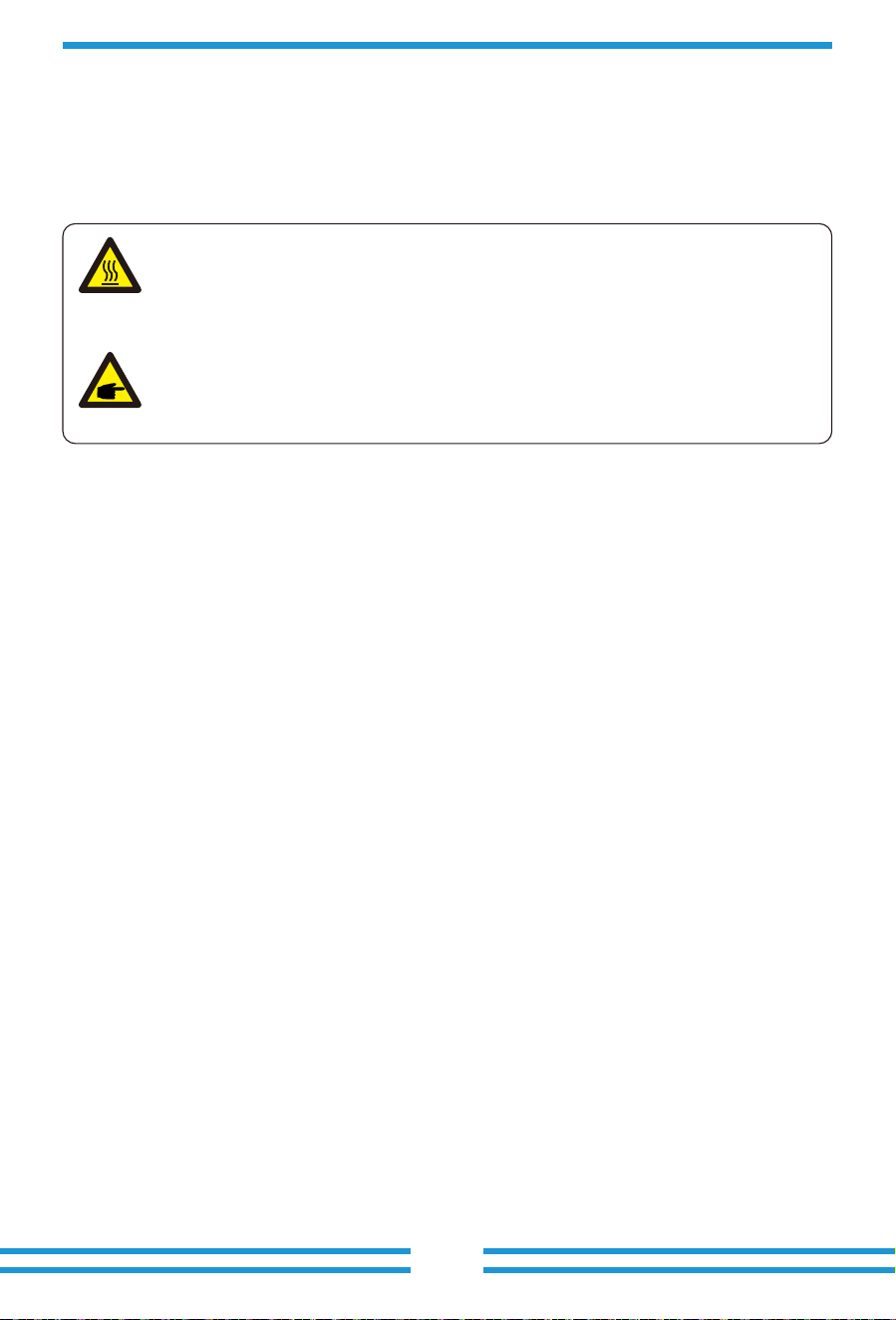
9. Repair and Maintenance
10.Error informa�on and processing
10.1 Error code
String type inverter doesn’t need regular maintenance. However, debris or dust will affect heat
sink’s thermal performance. It is be�er to clean it with a so� brush. If the surface is too dirty
and affect the reading of LCD and LED lamp, you can use wet cloth to clean it up.
If there is any failure,the LCD screen will display an alarm message. In this case, the inverter
may stop feeding energy into the grid. The alarm descrip�on and their corresponding alarm
messages are listed Table 10.1.
Warning:
When the device is running, the local temperature is too high and the touch can
cause burns. Turn off the inverter and wait for it cooling, then you can clean and
maintain.
Warning:
No solvent, abrasive materials or corrosive materials can be used for cleaning
any parts of the inverter.
Inverter has been designed in accordance with interna�onal grid �ed standards for safety,
and electromagne�c compa�bility requirements. Before delivering to the customer the
inverter has been subjected to several tests to ensure its op�mal opera�on and reliability.
- 39 -
Error code Descripon Ongrid - Three Phase
F01 DC input polarity reverse fault Check the PV input polarity.
F03 DC leakage current fault Hardly appear the code. Never ever happened so far.
F07 GFDI blown fuse Hardly appear the code. Never ever happened so far.
F11 AC main contactor errors Hardly appear the code. Never ever happened so far.
F12 AC auxiliary contactor errors Hardly appear the code. Never ever happened so far.
F14 DC firmware over current Hardly appear the code. Never ever happened so far.
F08 GFDI grounding touch failure Hardly appear the code. Never ever happened so far.
F02
DC insula�on impedance
permanent fault
Check the grounding cable of inverter.
F04
Ground fault GFDI Check the solar panel output connec�on.
F17
Hardly appear the code. Never ever happened so far.
F09
IGBT damaged by excessive drop
voltage
Hardly appear the code. Never ever happened so far.
F10
Auxiliary switch power supply
failure
F05
Read the memory error
Failure in reading memory (EEPROM). Restart the inverter if the
fault s�ll exists, contact your installer or Deye service.
F06
Write the memory error
Failure in wri�ng memory (EEPROM). Restart the inverter if the
fault s�ll exists, contact your installer or Deye service.
1. It tells the DC 12V is not existed.
2. Restart the inverter, if the fault s�ll exists, please contact y
our installer.
F13
Working mode changed/Grid
mode changed
1. Lost of one phase or AC voltage detec�on circuit or relays not
closed (old inverter not have relays detec�on func�on).
2. Restart the inverter, if the error s�ll exists, please contact your
installer or Deye service.
F20
DC over current fault of the
hardware
1. Check whether solar panel output current is within the
allowed range.
2. Check DC current sensor and its detec�on circuit.
3. Check if the inverter FW version is suitable for the hardware.
4. Restart the inverter, if the error s�ll exists, please contact your
installer or Deye service.
F15
AC firmware over current
1. The internal AC sensor or detec�on circuit on control board
or connec�on wire may loose.
2. Restart the inverter, if the error s�ll exists, please contact
your installer or Deye service.
F18
AC over current fault of hardware
1. Check AC sensor or detec�on circuit on control board or
connec�on wire.
2. Restart the inverter or factory reset, if the error s�ll exists,
please contact your installer or Deye service.
F16
GFCI(RCD) Ac leakage current
fault
1. This fault means the average leakage current is over 300mA.
Check whether DC power supply or solar panels is ok, then
check 'Test data'-> 'diL'value is about 40; Then check the
leakage current sensor or circuit (the following picture).
Checking test data needs using big LCD.
2. Restart the inverter, if the error s�ll exists, please contact your
installer or Deye service.
Three phase current,
over-current fault
F19
Hardly appear the code. Never ever happened so far.
All hardware failure synthesis
- 40 -
Error code Descripon Ongrid - Three Phase
F25 DC feedback fault Hardly appear the code. Never ever happened so far.
F27 DC end insula�on error Hardly appear the code. Never ever happened so far.
F28 Inverter 1 DC high fault Hardly appear the code. Never ever happened so far.
F29 AC load switch failure Hardly appear the code. Never ever happened so far.
F32 Inverter 2 dc high fault Hardly appear the code. Never ever happened so far.
F33 AC over current Hardly appear the code. Never ever happened so far.
F34 AC current over load Hardly appear the code. Never ever happened so far.
F36 AC grid phase error Hardly appear the code. Never ever happened so far.
F26
The DC busbar is unbalanced
1. Check whether the 'BUSN' cable or driver board power supply
cable is loose.
2. Restart the inverter, if the fault s�ll exists, contact your
installer or Deye service.
F31
Dc boost so� start
1. At least one Relay can't be closed. Check relays and its driver
signal. (Old inverter not have relays detec�on func�on)
2. Restart the inverter, if the fault s�ll exists, contact your
installer or Deye service.
F35
No AC grid
1. Check AC grid voltage. Check AC voltage detec�on circuit.
Check if the AC connector in good condi�on. Check whether
the AC grid is normal in voltage.
2. Restart the inverter, if the fault s�ll exists, contact your
installer or Deye service.
F30
AC main contactor failure
1. Check relays and AC voltage of relays.
2. Check relays driver circuit. Check if the so�ware is not suitable
for this inverter. (Old inverter not have relays detec�on
func�on)
3. Restart the inverter, if the fault s�ll exists, contact your
installer or Deye service.
F23
AC leakage current is transient
over current
1. This fault means the leakage current is above 30mA suddenly.
Check whether DC power supply or solar panels is ok, then
check 'Test data'-> 'diL'value is about 40; Then check the
leakage current sensor or circuit. Check test data needs
using big LCD.
2. Restart the inverter, if the fault s�ll exists, contact your installer
or Deye service.
F24
DC insula�on impedance failure
1. Check Vpe resistance on main board or detec�on on control
board. Check PV panels is OK. Many �mes this issue is the PV
problem.
2. Check whether the PV panel (aluminum frame) is grounded
well and inverter is grounded well. Open the cover of inverter
and then check the inside ground cable is fixed well on the shell.
3. Check if the AC/DC cable, terminal block are shorted to ground
or the insula�on is damaged.
4. Restart the inverter, if the fault s�ll exists, contact your installer
or Deye service.
F37
AC three-phase voltage unbalance
failure
Hardly appear the code. Never ever happened so far.
F38
AC three-phase current unbalance
failure
Hardly appear the code. Never ever happened so far.
F22
Contact your installer for help.
Crash stop (if there is a stop
bu�on)
F21
Hardly appear the code. Never ever happened so far.DC leakage flow fault
- 41 -
Error code Descripon Ongrid - Three Phase
F40 DC over current Hardly appear the code. Never ever happened so far.
F39
AC over current(one cycle)
1. Check AC current sensor and its circuit.
2. Restart the inverter, if the fault s�ll exists, contact your
installer or Deye service.
F41
AC Line W,U over voltage
Check the AC voltage protec�on se�ng. And Check if the AC
cable is too thin.Check the voltage difference between LCD and
meter.
F55
DC busbar voltage is too high
1. Check PV voltage and Ubus voltage and its detec�on circuit.
If the PV input voltage exceeds the limit, please reduce the
number of solar panels in series.
2. For Ubus voltage, please check the LCD display.
F56
DC busbar voltage is too low
1. It tells the PV input voltage is low and it always happens in the
early morning.
2. Check PV voltage and Ubus voltage. When inverter is running,
then showing F56, maybe Loss of driver or need update
firmware.
3. Restart the inverter, if the fault s�ll exists, contact your
installer or Deye service.
F43
AC Line V,W over voltage
Check the AC voltage protec�on se�ng.And Check if the AC
cable is too thin.Check the voltage difference between LCD and
meter.
F45
AC Line U,V over voltage
Check the AC voltage protec�on se�ng.And Check if the AC
cable is too thin.Check the voltage difference between LCD and
meter.
F42
AC Line W,U low voltage
Check the AC voltage protec�on se�ng. Check the voltage
difference between LCD and meter. Also need to check whether
AC cables are all firmly and correctly connected.
F44
AC Line V,W low voltage
Check the AC voltage protec�on se�ng. Check the voltage
difference between LCD and meter. Also need to check whether
AC cables are all firmly and correctly connected.
F46 AC Line U,V low voltage Check the AC voltage protec�on se�ng.
F47 AC Over frequency Check the frequency protec�on se�ng.
F57 AC reverse irriga�on AC reverse irriga�on.
F58 AC grid U over current Hardly appear the code. Never ever happened so far.
F48 AC lower frequency Check the frequency protec�on se�ng.
F49
U phase grid current DC
component over current
Hardly appear the code. Never ever happened so far.
F50
V phase grid current DC
component over current
Hardly appear the code. Never ever happened so far.
F51
W phase grid current DC
component over current
Hardly appear the code. Never ever happened so far.
F52
AC inductor A, phase current
DC current high
Hardly appear the code. Never ever happened so far.
F53
AC inductor B, phase current
DC current high
Hardly appear the code. Never ever happened so far.
F54
AC inductor C, phase current
DC current high
Hardly appear the code. Never ever happened so far.
- 42 -
1. Serial number of the inverter;
2. The distributor/dealer of the inverter(if available);
3. Installa�on date;
4. The discrip�on of problem(include LCD'error code and LED starus indicator lights);
5. Your contact details.
Note:
If your string inverter has any of the fault informa�on shown in Table 10-1, and
when you reset the machine and s�ll don’t solve the problem, please contact our
distributor and provide the below details:
F64
IGBT heat sink high temperature
1. Check temperature sensor. Check if firmware is suitable for
the hardware. Check if the inverter is its right model.
2. Restart the inverter, if the fault s�ll exists, contact your
installer or Deye service.
F59 AC grid V over current Hardly appear the code. Never ever happened so far.
F60 AC grid W over current Hardly appear the code. Never ever happened so far.
F61 Reactor A phase over current Hardly appear the code. Never ever happened so far.
F62 Reactor B phase over current Hardly appear the code. Never ever happened so far.
F63 Reactor C phase over current Hardly appear the code. Never ever happened so far.
Error code Descripon Ongrid - Three Phase
Table10.1 Error codes and their solu�ons
- 43 -
11.Specifica�on
MC-4 mateableDC Connec�on
IP65 rated plugAC Connec�on
LCD 240 × 160Display
RS485/RS232/Wifi/LANInterface
DC Injec�on Current(mA)
Grid Frequency Range
Max.Efficiency
Euro Efficiency
>99%MPPT Efficiency
Model
Input Side
Output Side
Efficiency
General Data
General Data
Max.DC Power(kW)
Max.DC Input Voltage(V)
Start-up DC Input Voltage(V)
MPPT Opera�ng Range(V)
Max.DC Input Current(A)
Number of MPPT/Strings per MPPT
Rated Output Power(kW)
Max.Ac�ve Power(kW)
Rated AC Grid Voltage(V)
AC Grid Voltage Range(V)
Rated Grid Frequency(Hz)
Opera�ng Phase
Rated AC Grid Output Current(A)
Max.AC Output Current(A)
Output Power Factor
<0.5%
47-52 or 57-62(op�onal)
98.7%
98%
250
1000
200~850
40+40+40
40+40+40+40
220/380, 230/400
277 ~ 460 (this may vary with grid standards)
50/60(Op�onal)
Three phase
0.8 leading to 0.8 lagging
<2%Grid Current THD
647.5×537×303.5
Transformerless
Size(mm, W×H×D)
44.5Weight(kg)
Topology
<1W(Night)Internal consump�on
-25 ~ 65℃
Opera�ng temperature
Ingress protec�on IP65
<45dB
Smart cooling
Max. opera�on al�tude
Cooling Concept
Noise Emission(Typical)
2000m
>20 YearsDesigned Life�me
EN50549, IEC61727, VDE 0126-1-1, IEC62109-1-2Grid Connec�on Standard
Opera�on surrounding humidity 0~100%
IEC62109-1/-2, EN61000-6-1, EN61000-6-3Safety EMC / Standard
2/3
40+40
SUN-30K
-G03
39
30
33
43.5
47.8
40+40+40
3/3
SUN-33K
-G03
42.9
33
36.3
48
52.8
40+40+40
SUN-35K
-G03
45.5
3/3
35
38.5
50.7
55.8
40+40+40
SUN-40K
-G03
52
3/3
40
44
58
63.8
3/3
SUN-45K
-G03
58.5
45
49.5
65.2
71.7
4/3
SUN-50K
-G03
65
50
55
72.4
79.7

Add: No.26-30, South Yongjiang Road, Beilun, 315806, Ningbo, China
Fax: +86 (0) 574 8622 8852
Tel: +86 (0) 574 8622 8957
E-mail: [email protected]
Web: www.deyeinverter.com
502011957 Ver: 1.0, 2020-11