WEEE Number: 80133970
INSTRUCTION MANUAL
ON-GRID INVERTER SINGLE PHASE
MULTI-LANGUAGE MANUAL QR CODE
Please scan the QR code to access the manual in
multiple languages.
IN CASE OF ANY QUERY/ISSUE WITH THE PRODUCT, PLEASE REACH OUT TO US AT: SUPPORT@V-TAC.EU
FOR MORE PRODUCTS RANGE, INQUIRY PLEASE CONTACT OUR DISTRIBUTOR OR NEAREST DEALERS.
V-TAC EUROPE LTD. BULGARIA, PLOVDIV 4000, BUL.L.KARAVELOW 9B
MODEL
SKU
HNS5000TL
11979
HNS6000TL
11980
Thank you for selecting and buying V-TAC product. V-TAC will serve you the best. Please read these instructions
carefully before starting the installation and keep this manual handy for future reference. If you have any another
query, please contact our dealer or local vendor from whom you have purchased the product. They are trained
and ready to serve you at the best. The warranty is valid for 5 years from the date of purchase. The warranty does
not apply to damage caused by incorrect installation or abnormal wear and tear. The company gives no warranty
against damage to any surface due to incorrect removal and installation of the product. This product is warranted
for manufacturing defects only.

Contents
1. About This Manual . . . . . . . . . . . . . . . . . . . . . .
1.1 Scope of Validity . . . . . . . . . . . . . . . . . . . . . . . . . . . . .
1.2 Target Group . . . . . . . . . . . . . . . . . . . . . . . . . . . . . . .
1.3 System Diagram . . . . . . . . . . . . . . . . . . . . . . . . . . . . .
2. Safety & Symbols . . . . . . . . . . . . . . . . . . . . . . .
2.1 Safety Precautions . . . . . . . . . . . . . . . . . . . . . . . . . . . .
2.2 Explanations of Symbols . . . . . . . . . . . . . . . . . . . . . . . . .
3. Installation . . . . . . . . . . . . . . . . . . . . . . . . . .
3.1 Pre-installation . . . . . . . . . . . . . . . . . . . . . . . . . . . . . .
3.1.1 Unpacking & Package List . . . . . . . . . . . . . . . . . . . . . . . .
3.1.2 Product Overview . . . . . . . . . . . . . . . . . . . . . . . . . . . .
3.1.3 Mounting Location . . . . . . . . . . . . . . . . . . . . . . . . . . .
3.2 Mounting . . . . . . . . . . . . . . . . . . . . . . . . . . . . . . . . .
4. Electrical Connection. . . . . . . . . . . . . . . . . . . . .
4.1 PV Connection . . . . . . . . . . . . . . . . . . . . . . . . . . . . . .
4.2 Grid Connection . . . . . . . . . . . . . . . . . . . . . . . . . . . . . .
4.3 Communication Connection . . . . . . . . . . . . . . . . . . . . . . .
4.4 Zero-injection Smart Meter (Optional) . . . . . . . . . . . . . . . . . .
5. Operation . . . . . . . . . . . . . . . . . . . . . . . . . . .
5.1 Control Panel . . . . . . . . . . . . . . . . . . . . . . . . . . . . . . .
5.2 Menu Structure . . . . . . . . . . . . . . . . . . . . . . . . . . . . . .
5.3 Setting . . . . . . . . . . . . . . . . . . . . . . . . . . . . . . . . . . .
5.3.1 Startup . . . . . . . . . . . . . . . . . . . . . . . . . . . . . . . . .
5.3.2 Voltage Range . . . . . . . . . . . . . . . . . . . . . . . . . . . . .
5.3.3 Frequency Range . . . . . . . . . . . . . . . . . . . . . . . . . . . .
6. Commissioning . . . . . . . . . . . . . . . . . . . . . . .
7. Start-up & Shut Down . . . . . . . . . . . . . . . . . . . .
7.1 Shut down . . . . . . . . . . . . . . . . . . . . . . . . . . . . . . . .
7.2 Restart . . . . . . . . . . . . . . . . . . . . . . . . . . . . . . . . . .
8. Maintenance&Trouble Shooting . . . . . . . . . . . . . . .
8.1 Maintenance . . . . . . . . . . . . . . . . . . . . . . . . . . . . . . .
8.2 Trouble Shooting . . . . . . . . . . . . . . . . . . . . . . . . . . . . .
9. Specifications . . . . . . . . . . . . . . . . . . . . . . . .
Contents
20
20
20
20
21
21
21
25
8
8
11
13
14
16
16
17
18
18
18
19
1
1
1
1
2
2
3
4
4
4
5
6
7
1. About This Manual
1.1 Scope of Validity
1.2 Target Group
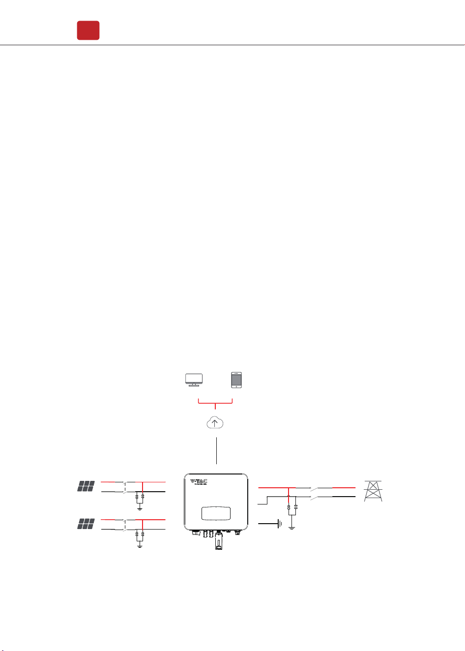
1.3 System Diagram
This manual describes the installation, commissioning, operation and
maintenance of the following on-grid PV inverters produced by VTAC:
This manual is for qualified personnel. The tasks described in this manual must
only be performed by qualified personnel.
Single Phase Ongrid Inverter:
HNS5000TL HNS6000TL
Please Keep This Manual All The Time Available In Case Of Emergency.
The typical on-grid PV system connection diagram.
About This Manual
01
Circuit Breaker 1
Surge Protective
Device
DCA1+
DCA1-
PE
WIFI / RS485
Cloud server
Portal web Porta Smart-phone
PVA1
PV Array
Circuit Breaker
N
L
3
AC Grid
Surge Protective
Device
Circuit Breaker 1
Surge Protective
Device
DCA1+
DCA1-
PVA1
PV Array
PV Inverter
Type Max AC Current (A) Rated current of AC breaker (A)
Single Phase Ongrid Inverter
Safety & Symbols
02
Note:
The Inverter can be only connected to low-voltage grid.
(220/230Vac, 50/60Hz).
Surge Protector Recommendation
• AC side, nominal discharge current 20KA, second grade lightning protection,
protection voltage 2.5KV.
• DC side, nominal discharge current 20KA, second grade lightning protection,
protection voltage 3.2KV.
• The wiring distance between the inverter and the distribution box should be at
least 5 meters.
2. Safety & Symbols
2.1 Safety Precautions
1. All work on the inverter must be carried out by qualified electricians.
2. The device may only be operated with PV panels.
3. The PV panels and inverter must be connected to the ground.
4. Do not touch the inverter cover until 5 minutes after disconnecting both DC
and AC power supply.
Circuit Breaker Recommendation
HNS5000TL
HNS6000TL
23
28
32
40
Safety & Symbols
03
5. Do not touch the inverter enclosure when operating, keep away from materials
that may be affected by high temperatures.
6. Please ensure that the used device and any relevant accessories are disposed
of in accordance with applicable regulations.
7. VTAC inverter should be placed upwards and handled with care in delivery. Pay
attention to waterproof. Do not expose the inverter directly to water, rain, snow or
spray.
8. Alternative uses, modifications to the inverter not recommended. The warranty
can become void if the inverter was tampered with or if the installation is not in
accordance with the relevant installation instructions.
VTAC inverter strictly comply with relevant safety standards. Please read and
follow all the instructions and cautions during installation, operation and
maintenance.
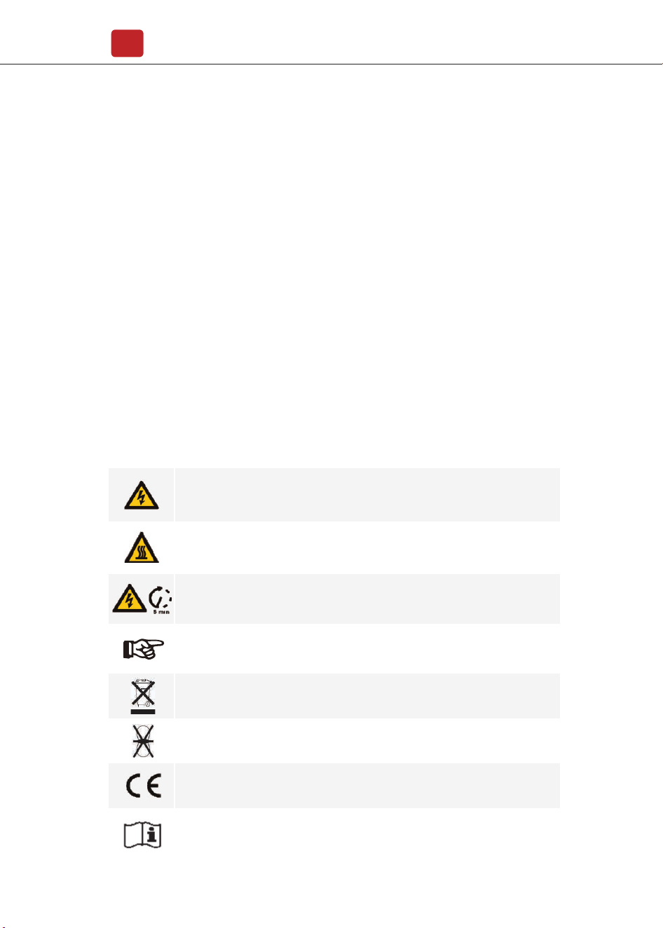
2.2 Explanations of Symbols
Danger of electric shock
The inverter contains fatal DC and AC power. All work on the inverter
must be carried out by qualified personnel only.
Beware of hot surface
The inverter’s housing may reach uncomfortably hot 60°C (140°F) under high
power operation. Do not touch the inverter enclosure when operation.
Residual power discharge
Do not open the inverter cover until 5 minutes after disconnection both
DC and AC power supply.
Do not dispose of this device with the normal domestic waste.
Without transformer
This inverter does not use transformer for the isolation function.
CE mark
The inverter complies with the requirements of the applicable
CE guidelines.
Refer to manual before service.
Important notes
Read all instructions carefully. Failure to follow these instructions,
warnings and precautions may lead to device malfunction or damage.
Installation
04
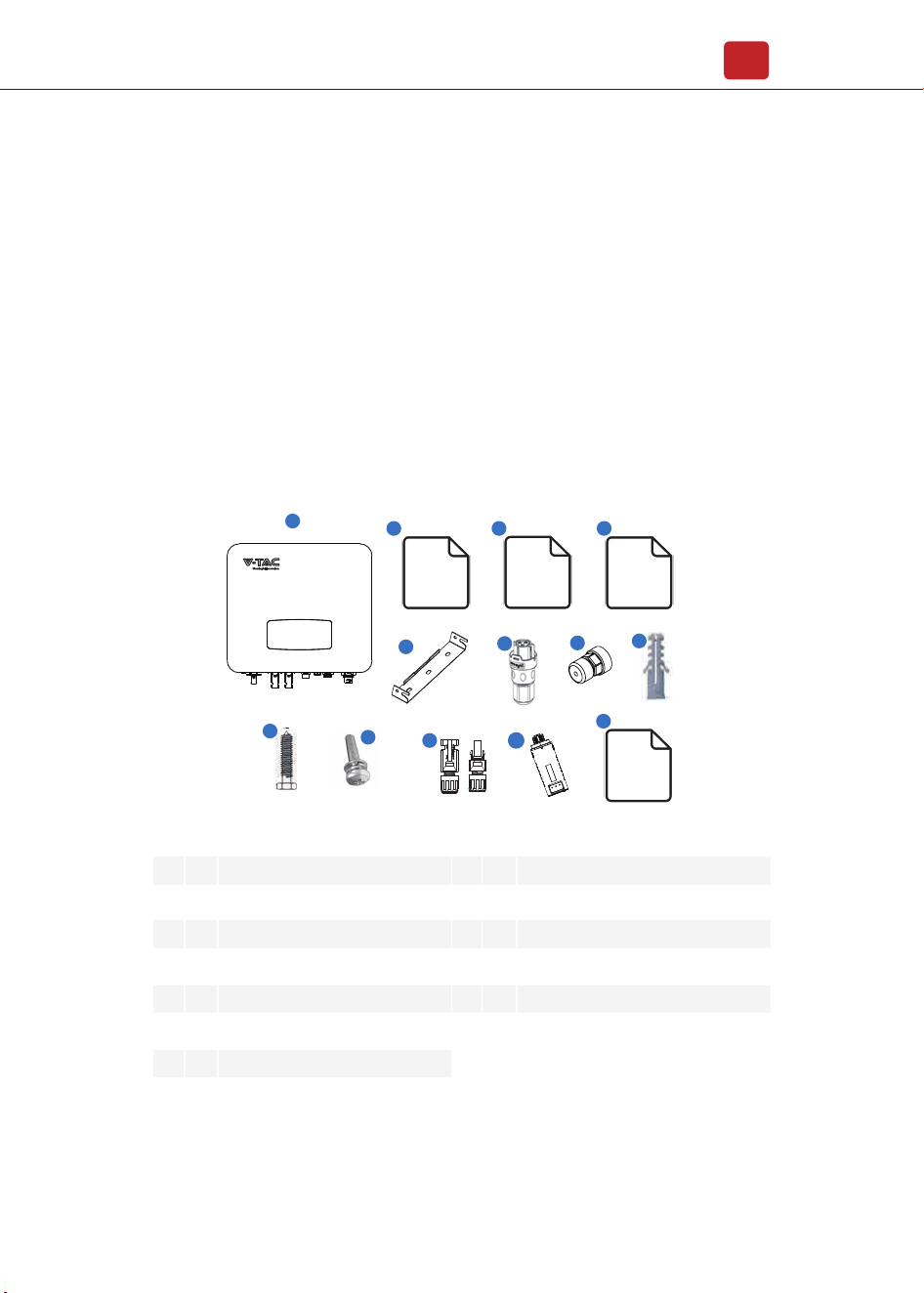
No.
1
2
3
4
5
6
7
1
1
1
1
1
1
1
Solar inverter
Certificate Of Inspection
Quick Installation Instructions
Warranty Card
Wall Mounting Bracket
AC Connector
Zero-Injection Connector (Optional)
8
9
10
11
12
13
3
3
1
2
1
1
Plastic Expansion Tube
Tapping Screw
Security Screw
DC Connector sets
Monitor Module
Monitoring Quick Installation Instructions
Qty Items No. Qty Items
3. Installation
3.1 Pre-installation
3.1.1 Unpacking & Package List
Unpacking
On receiving the inverter, please check to make sure the packing and all
components are not missing or damaged. Please contact your dealer directly for
supports if there is any damage or missing components.
Package List
Open the package, please check the packing list shown as below.
6
7
8
9
10
11
12
MC
STOP
�
MC
1
2 3 4
5
Certificate
Of
Inspection
Warranty
Card
Quick
Installation
Instructions
13
Monitoring
Module
Quick
Installation
Instructions
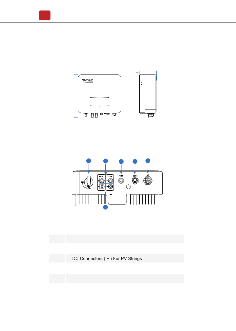
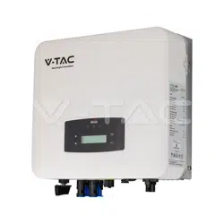
Inverter Terminals
3.1.2 Product Overview
No.
1
2
3
4
5
6
DC Switch
DC Connectors ( + ) For PV Strings
AC Connector
Monitor Module Port
Zero-Injection Port (Optional)
Items
360 mm
358 mm
142 mm
1
2
3
4
5
6
Installation
05
Installation
06
<30°
>0°
Max
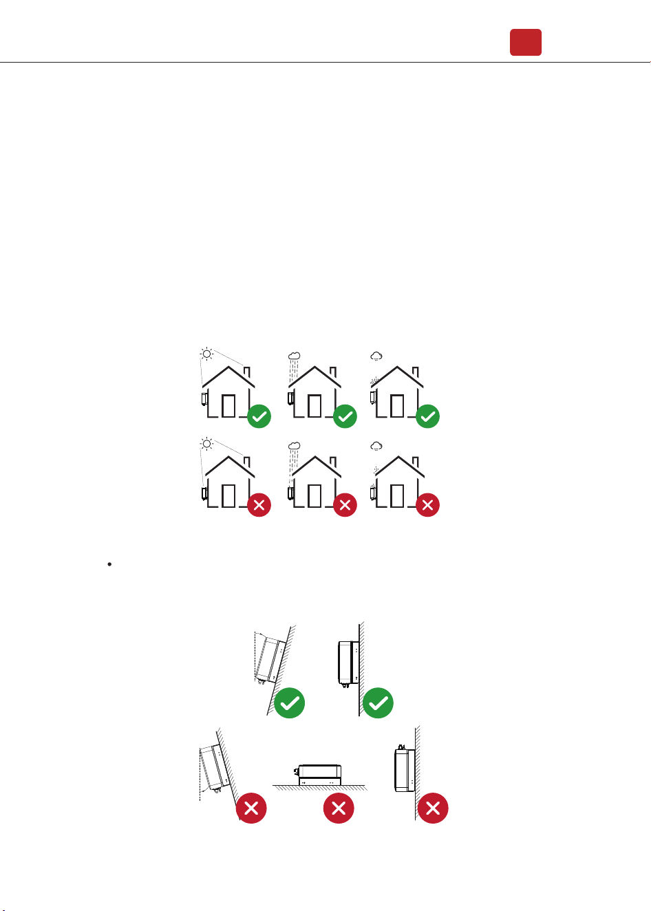
The inverters are designed for indoor and outdoor installation (IP65), to increase
the safety, performance and lifespan of the inverter, please select
the mounting location carefully based on the following rules:
• The inverter should be installed on a solid surface, far from flammable or
corrosion materials, where is suitable for inverter’s weight and dimensions.
• The ambient temperature should be within -25℃ ~ 60℃ (between -13 °F and
140°F).
• The installation of inverter should be protected under shelter. Do not expose
the inverter to direct sunlight, water, rain, snow, spray lightning, etc.
3.1.3 Mounting Location
The inverter should be installed vertically on the wall, or lean back on plane
with a limited tilted angle. Please refer to below picture.
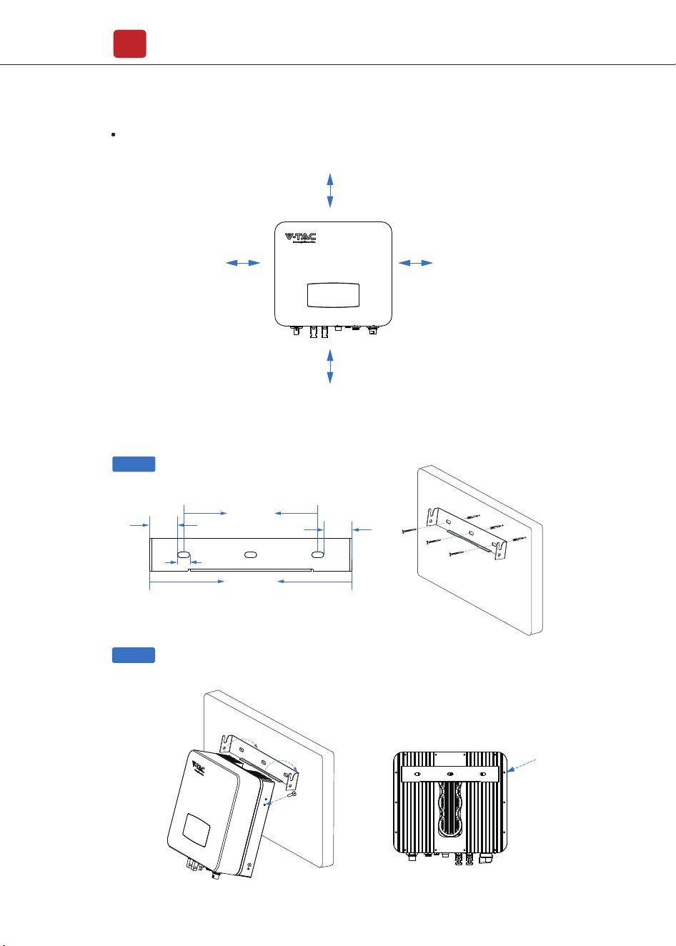
3.2 Mounting
Leave the enough space around inverter, easy for accessing to the inverter,
connection points and maintenance.
Step 1
Step 2
Installation
07
300mm
100mm 100mm
500mm
43.25mm
43.25mm
207mm
18.5mm
312mm
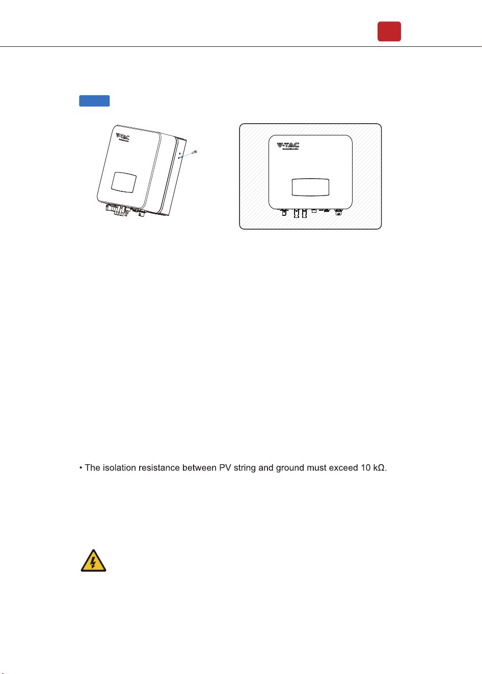
Security screw
4. Electrical Connection
4.1 PV Connection
Electrical Connection
08
Step 3
The inverter is equipped with 2 MPPT channels, each of which contains a PV
string input.
Security screw
For the best results, make sure that each MPPT channel is correctly connected
with PV string. Otherwise, the inverter will activate voltage or current protection
automatically.
Please make sure below requirements are followed:
• The open-circuit voltage and short-circuit current of PV string should not exceed
the reasonable range of the inverters.
• The polarity of PV strings are correct.
• Use the DC plugs in the accessory.
• The lightning protector should be equipped between PV string and inverter.
• Disconnect all of the PV (DC) switch during wiring.
Warning:
The fatal high voltage may on the DC side, please comply with
electric safety when connecting.
Please make sure the correct polarity of the cable connected with
inverter, otherwise inverter could be damaged.
Electrical Connection
09
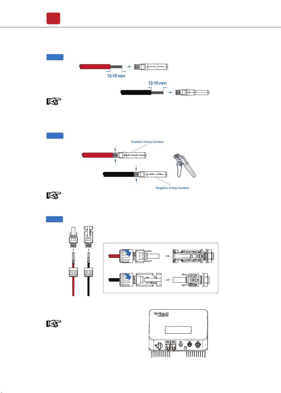
Step 1
Note:
PV cable suggestion
Cross-section
4mm²
Step 2
Note:
Please use PV connector crimper to pinch the point of the arrow.
Step 3
MC
STOP�
MC
MC
STOP�
MC
Note:
You’ll hear click sound when the
connector assembly is correct.
Electrical Connection
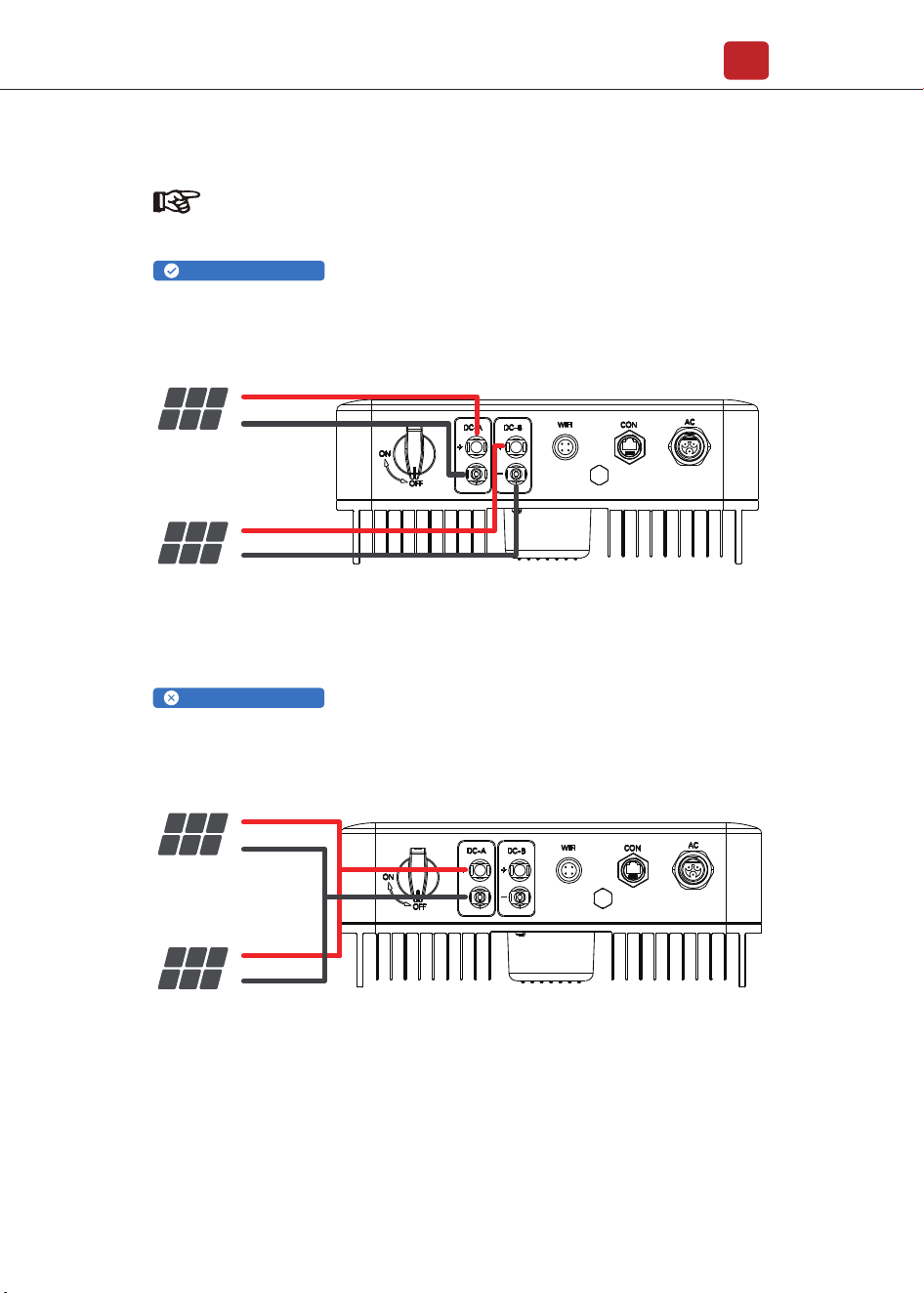
10
Do not connect more than two PV strings into one channel
Channel A and B connected with PV strings separately
PV Array 1
PV +
PV -
PV +
PV -
PV Array 2
PV Inverter
PV Array 1
PV +
PV -
PV +
PV -
PV Array 2
PV Inverter
Note:
PV string suggestion:
Correct Installation:
Wrong Installation:
Wrong Installation:
4.2 Grid Connection
Electrical Connection
11
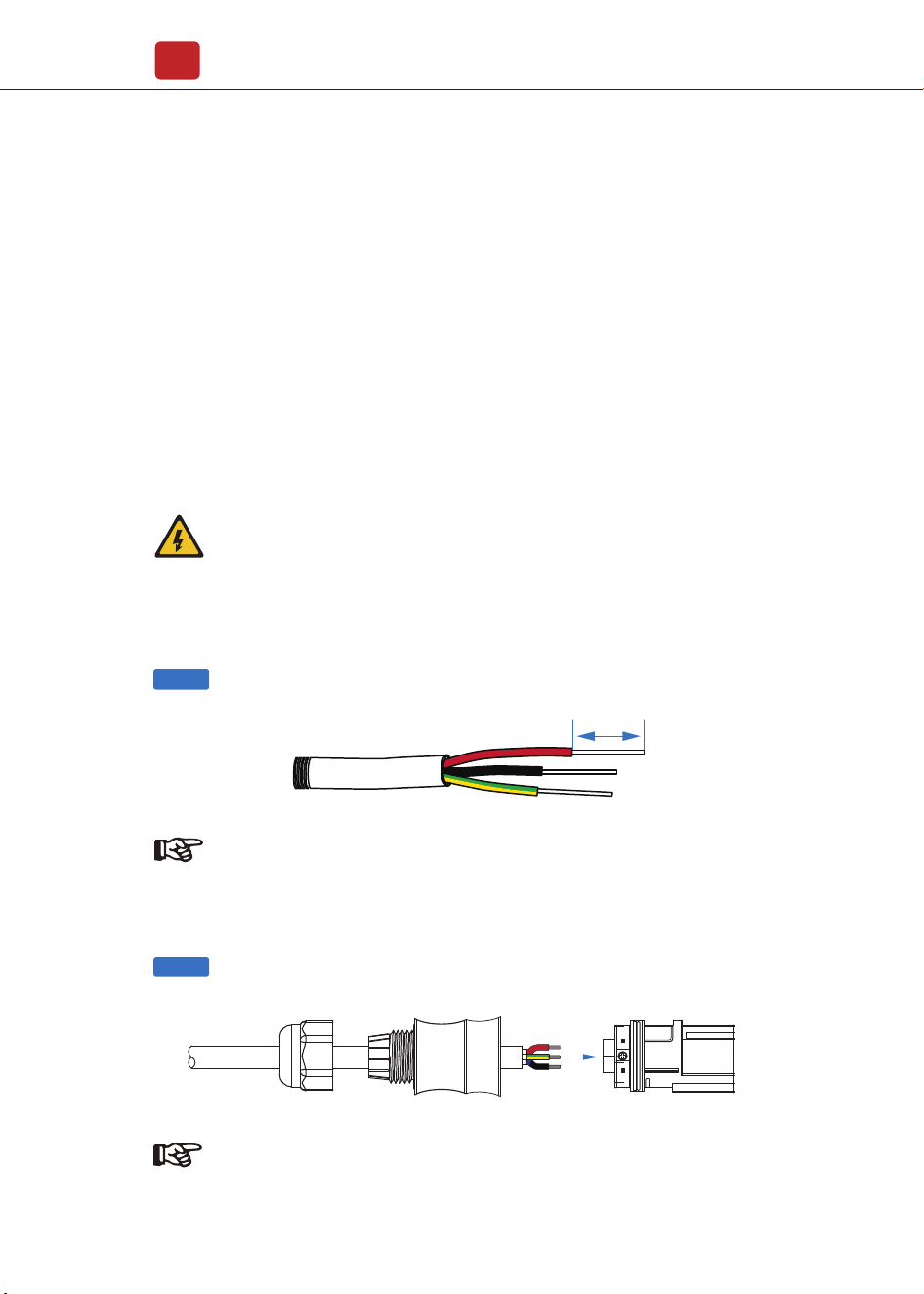
AC line goes through AC terminal waterproof head and cap
Step 1
Step 2
7mm
The external AC switch should be installed between inverter and grid to isolate
from grid. Please make sure below requirements are followed before connecting
AC cable to the inverter.
• The AC (grid) voltage should not exceed the reasonable range of the inverters.
• The phase-line from AC distribution box are correctly connected.
• Use the AC plugs in the accessory.
• The surge protector should be equipped between grid and inverter.
• Disconnect the AC (grid) switch during wiring.
Warning:
The fatal high voltage may on the AC side, please comply with
electric safety when connecting.
Please make sure the right line of AC grid connected with inverter,
otherwise inverter could be damaged.
Note:
AC cable suggestion
Cross-section
4mm²
Note:
Connect AC line, Live line (L), Neutral line (N) and Ground Wire (PE) according
to polarity.
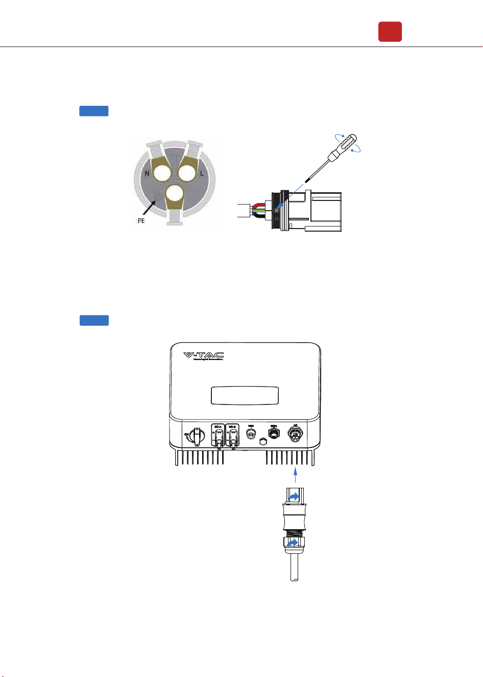
Step 3
Electrical Connection
12
Step 4
1. Connect AC terminals and waterproof
head, tighten the cap, make sure they
clip closely together.
2. Connect AC connector to AC terminal
of the inverter.
3. Afeer making sure that it is firmly
insered, tighten the sleeve on the AC
connector to the right and hear a click.
Step 1
Step 2
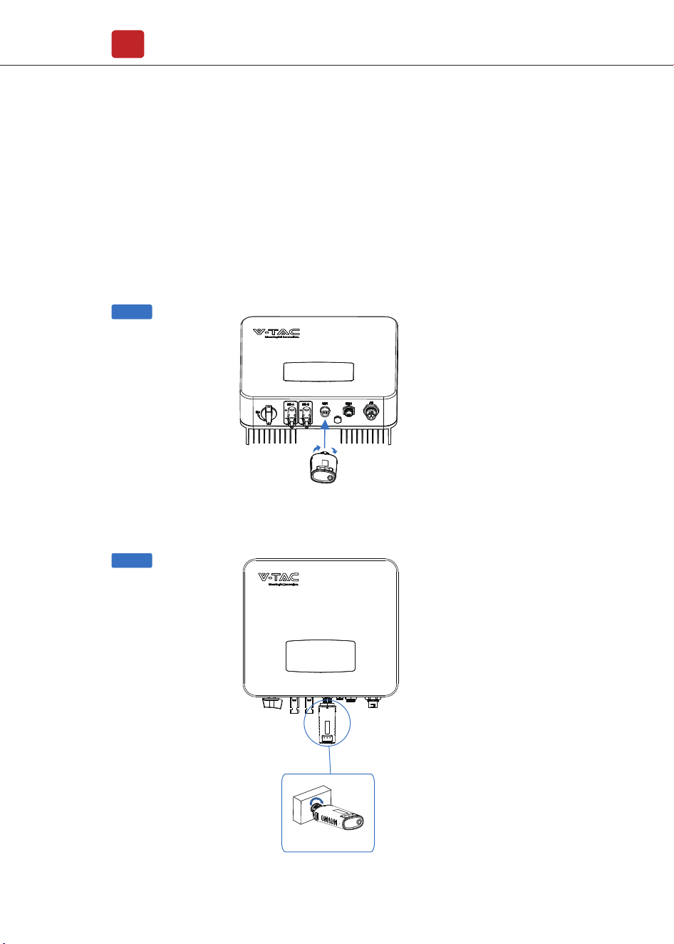
4.3 Communication Connection
Electrical Connection
13
Wifi/GPRS
The monitoring module could transmit the data to the cloud server, and display
the data on the PC, tablet and smart-phone.
WIFI / Ethernet / GPRS / RS485 communication is applicable to the inverter.
Please refer to "Communication Configuration Instruction" for detailed
instruction.
Install the WIFI / Ethernet / GPRS / RS485 Communication
Electrical Connection
14
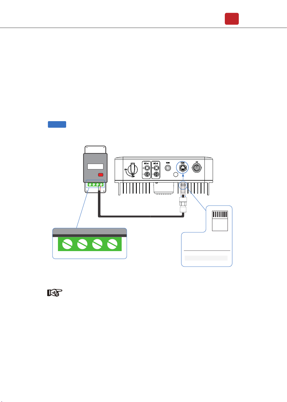
Step 1
For single-phase inverter, please follow below pin order
RS485A(Pin 7) to single-phase meter (Pin 24)
RS485B(Pin 8) to single-phase meter (Pin 25)
4.4 Zero-injection Smart Meter (Optional)
Smart meter is an intelligent control equipment which is used for on-grid
inverters. Its main function is to measure the forward and reverse power on
the grid-connected side, and transmit data to the inverter through RS485
communication to ensure that the power of the inverter is less than or equal
to the user's home load, and no current flows into the grid.
Note:
Afore Smart Meter
5 6 24 25
PIN Assignment
Zero-Injection Port pin assignment
12345678
RJ45 Plug
7
8
1-6
RS485 A ( 24 )
RS485 B ( 25 )
/
Smart Meter
Electrical Connection
15
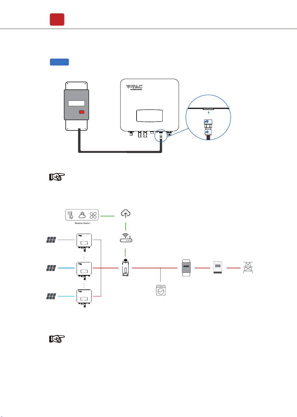
Step 2
Note:
The Inverter could be connected in parallel with Smart Meter,
make sure the total load power not exceed Smart Mater’s limitation.
Grid
Load
RS485 � WiFi � Ethernet � GPRS
Router
Cloud Server
Smart Meter
PV Array
Energy Meter
PV Inverter
PV Array
PV Array
Note:
Please refer to "Zero InjectionSmart Meter Installation andOperation
Manual" for detailed instruction.
Smart Meter
PV Inverter
PV Inverter
Operation
16
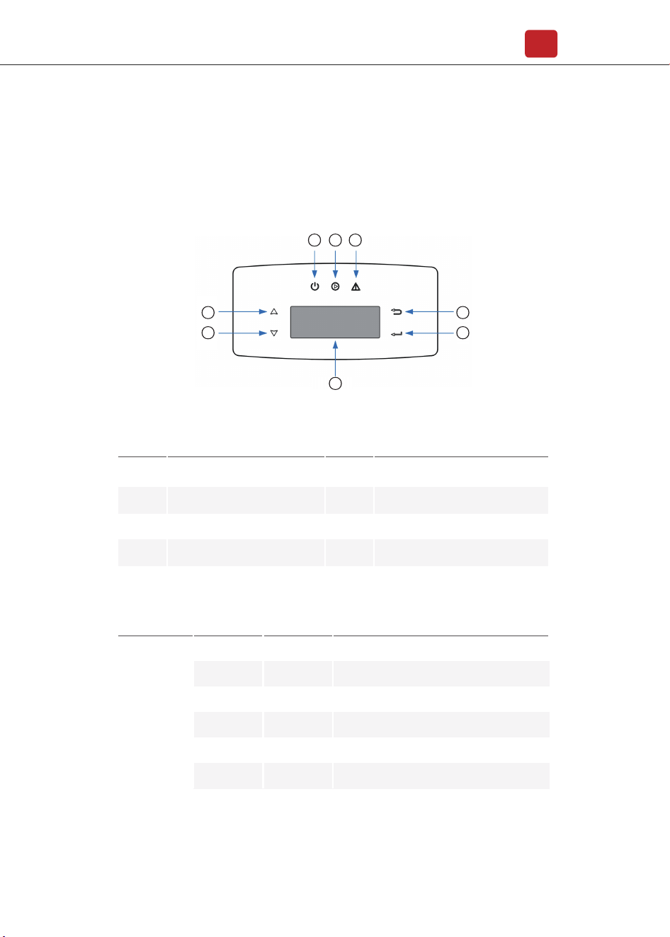
5. Operation
5.1 Control Panel
ItemsNNo. ItemsNNo.
1
2
3
4
LCD Display
ESC Touch Button
UP Touch Button
DOWN Touch Button
5
6
8
7
FAULT LED Indicator
POWER LED Indicator
ENT Touch Button
GRID LED Indicator
Sign Color Explanation
POWER
GreenON
OFF
ON
OFF
ON
OFF
Green
Red
FAULT
The inverter is stand-by
The inverter is power off
The inverter is feeding power
The inverter is not feeding power
Fault occurred
No fault
GRID
Power
2
3
1
4
5
6 7 8

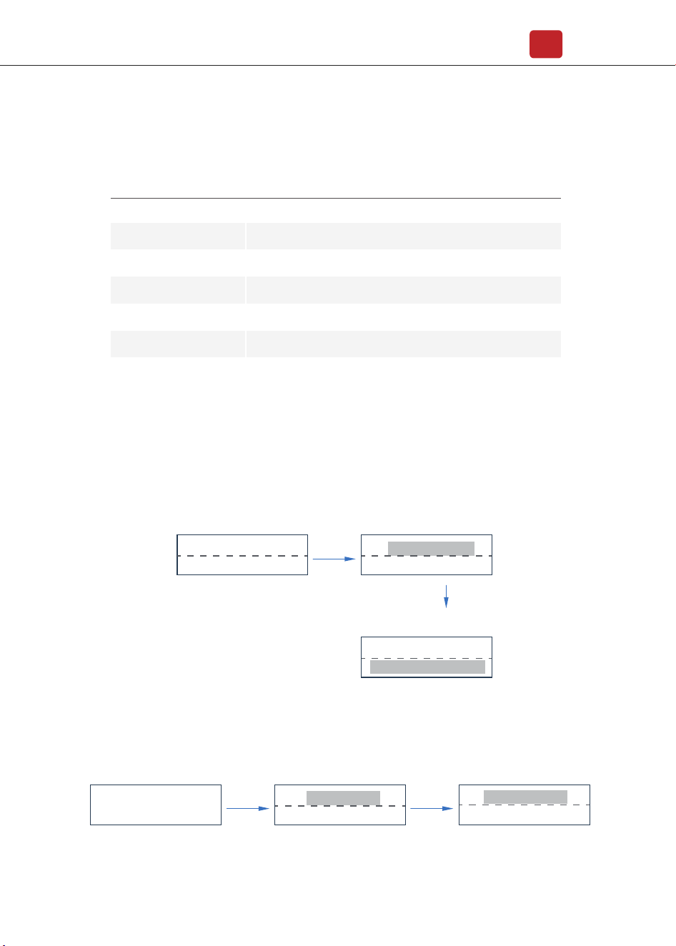
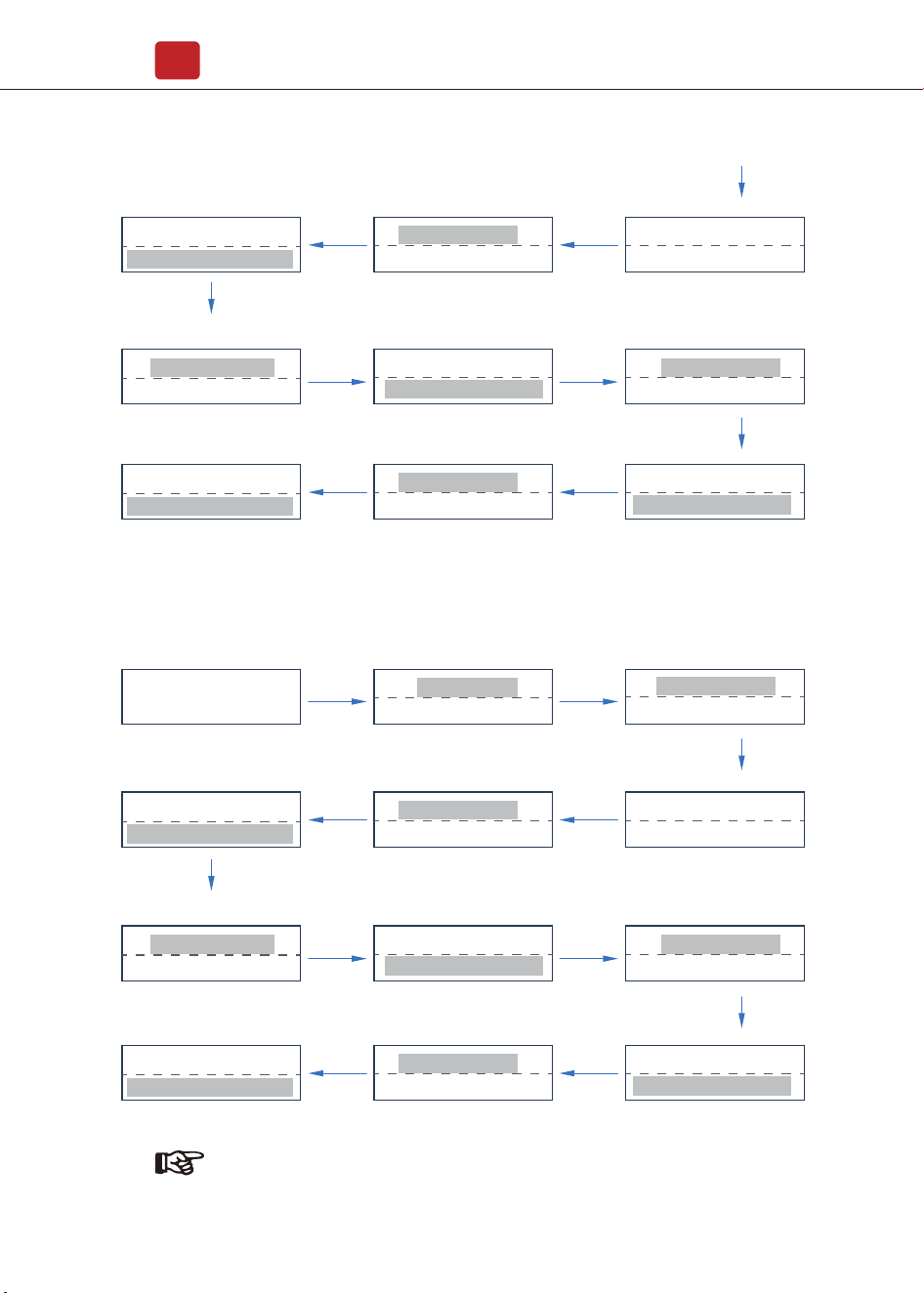
5.2 Menu Structure
Operation
17
Setting
PassWord xxxx
PassWord xxxx
PassWord xxxx
PassWord xxxx
PassWord xxxx
PassWord xxxx
PassWord xxxx
PassWord xxxx
PassWord xxxx
Safety
Output P%
Freq Range
Volt Range
Del Err Record
10min OVR
Coefficient
Del Arr Record
Q(Var)Mode
Inverter Info
HNS6000TL
Version:M Vxxx
Version:S Vxxx
Version:C Vxxx
S/N(Machine)S6xxxxxxxx
First Level Menu
Second Level Menu
Three Level Menu
Wifi Info
IP(Wifi)192.168.xx.xx
S/N(Wifi)xxxxxx
Error Record
No Error
Date&Time
Time: Hh:Mm:Ss
Date: 2021-Dd-Mm
Zero Injection
PassWord xxxx
PassWord xxxxFunction Enable
Operation
18
5.3.1 Startup
5.3 Setting
Explanation of LCD Display Content
Nouns Explanation
Inverter Info
Display the serial number and firmware version of inverter
Check the error list of inverter including date and time
Display the WIFI serial number and assigned IP address
Set date and time of the inverter
Countercurrent power switch
Set the protection parameters of inverter
Error Record
Wifi Info
Date & Time
Function Enable
Setting
5.3.2 Voltage Range
Main Menu
Setting
Zero Injection
Volt Range
Del Err Record
ENT ENT
UP/DOWN
choose Volt Range
UP/DOWN
choose Setting
Date&Tine
Setting
Normal
Power=xx W
ENT
Date: 2020-Dd-Mm
Time: Hh:Mm:Ss
ENT
UP/DOWN Adjust the time and
press ENT to confirm
UP/DOWN
Selection Date&Time
Meter switchZero Injection
Operation
19
5.3.3 Frequency Range
FL1=xxxHz
Time=xxx*20ms
FH2=xxxHz
Time=xxx*20ms
FH2=xxxHz
Time=xxx*20ms
Main Menu
Setting
Zero Injection
Freq Range
Volt Range
ENT ENT
ENT ENT
FL1=xxxHz
Time=xxx*20ms
FL2=xxxHz
Time=xxx*20ms
FL2=xxxHz
Time=xxx*20ms
ENT
ENTENT
PassWord
XXXX
FH1=xxxHz
Time=xxx*20ms
FH1=xxxHz
Time=xxx*20ms
ENT
ENTENT
ENT
Note:
The parameters setting only works after the inverter is restarted.
VL1=XXXV
Time=xxx*20ms
VH2=XXXV
Time=xxx*20ms
VH2=XXXV
Time=xxx*20ms
ENT ENT
VL1=XXXV
Time=xxx*20ms
VL2=XXXV
Time=xxx*20ms
VL2=XXXV
Time=xxx*20ms
ENT
ENTENT
PassWord
XXXX
VH1=XXXV
Time=xxx*20ms
VH1=XXXV
Time=xxx*20ms
ENT
ENTENT
ENT
UP/DOWN
choose Freq Range
UP/DOWN
choose Setting
UP/DOWN
set protection time
UP/DOWN set protection time
press ENT to confirm
UP/DOWN set level 2
frequency lower limit
UP/DOWN
set protection time
UP/DOWN
choose PassWord: xxxx
UP/DOWN
set protection time
UP/DOWN set level 1
frequency upper limit protection
UP/DOWN set level 2
frequency upper limit protection
UP/DOWN set level 1
frequency lower limit
UP/DOWN
set protection time
UP/DOWN set protection time
press ENT to confirm
UP/DOWN set level 2
voltage lower limit
UP/DOWN
set protection time
UP/DOWN
choose PassWord: xxxx
UP/DOWN
set protection time
UP/DOWN set level 1
voltage upper limit protection
UP/DOWN set level 2
voltage upper limit protection
UP/DOWN set level 1
voltage lower limit

Commissioning
20
Before starting up commissioning at site, please make sure below procedures
and requirements are fully meet.
• Mounting location is meet the requirements.
• All of the electrical wiring is firmly connected, including PV wiring, Grid wiring
and Earth wiring.
• The inverter setting has been finished accordingly to local standards or
regulations.
Commissioning Procedures
• Turn on the AC switch between inverter output and the public grid;
• Turn on the DC switch on the inverter;
• Turn on the PV switch of the system.
6. Commissioning
7. Start-up & Shut Down
• Turn off the DC switch on the inverter.
• Turn off the DC switch between PV panels and the inverter (if any).
• Close the AC switch between the inverter and the public grid.
• Shut down the inverter according to Chapter 7.1.
• Start-up the inverter according to Chapter 6.
7.2 Restart
7.1 Shut down
Note:
The inverter will be operable after minimum 5 minutes.

Periodically maintenance are necessary, please follow steps as below.
PV connection: twice a year
AC connection : twice a year
Earth connection: twice a year
Heat sink: clean with dry towel once a year.
Fault messages will be displayed when fault occurs, please according to
trouble- shooting table find related solutions.
8. Maintenance&Trouble Shooting
8.1 Maintenance
8.2 Trouble Shooting
Maintenance&Trouble Shooting
21
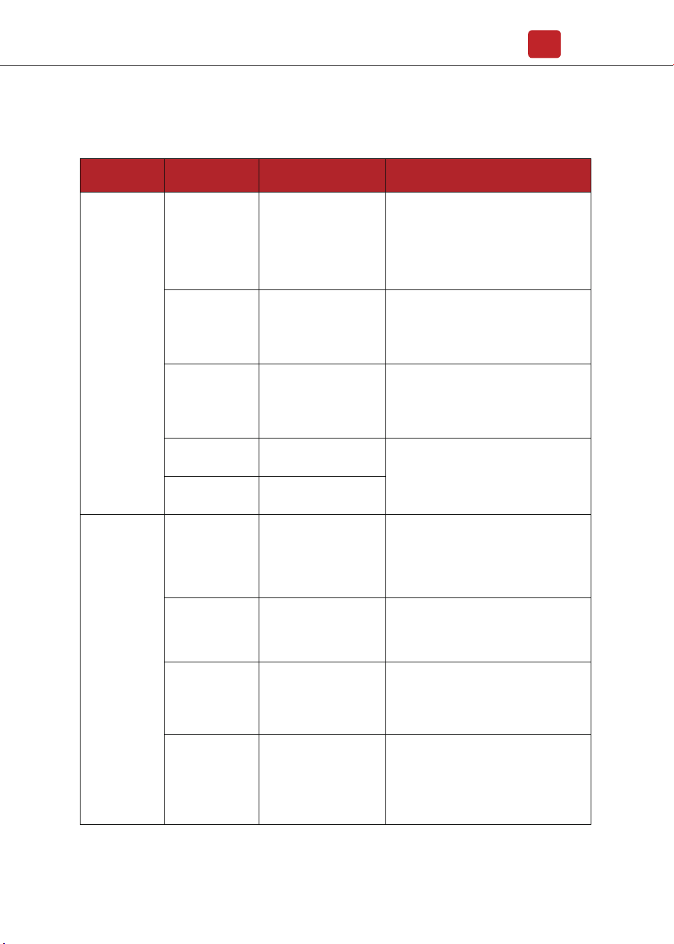
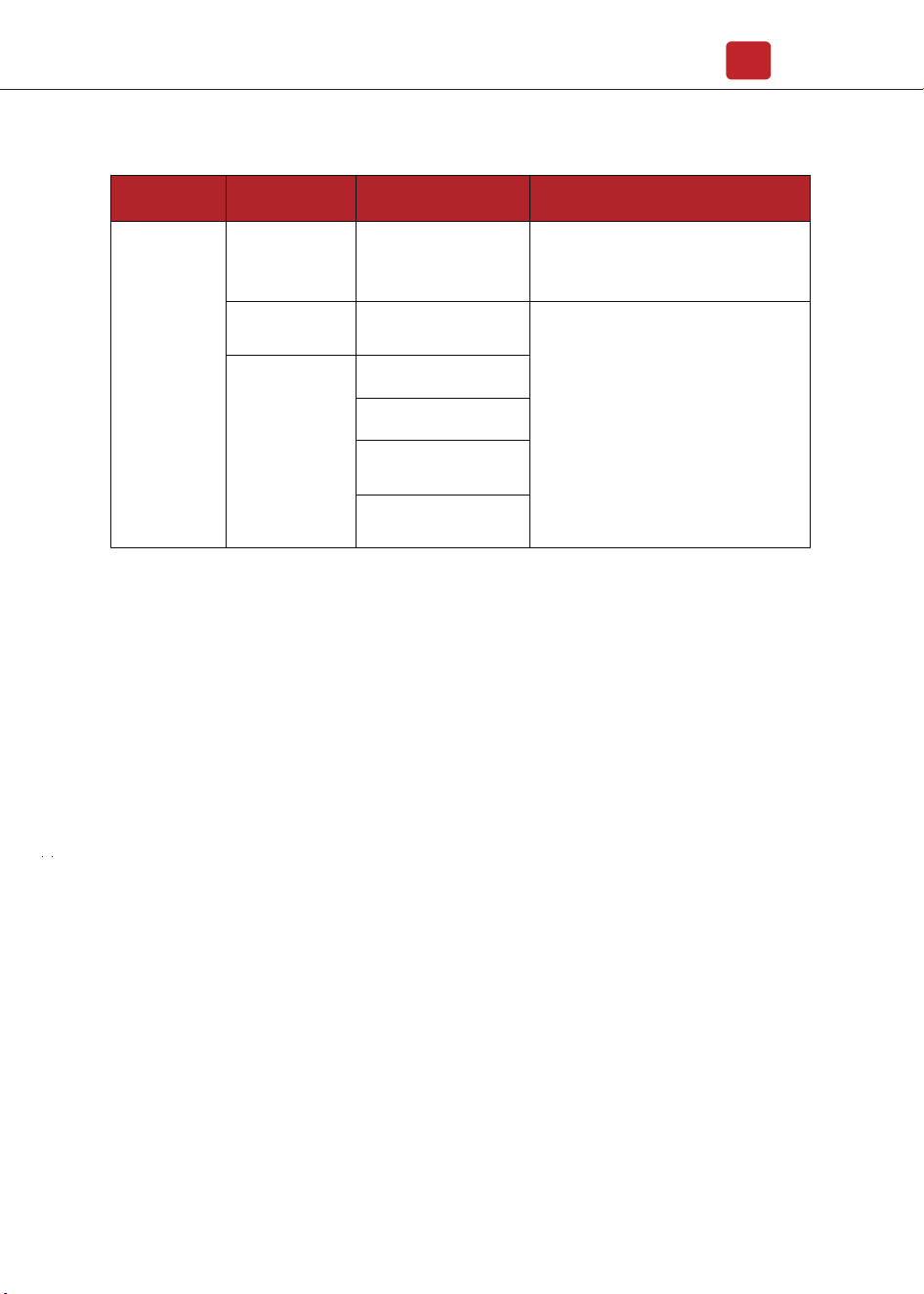
Trouble-Shooting List
Type of Fault Name Description Recommend Solution
Island Fault
Grid Fault
The public grid is outage
or the grid is disconnected
to the inverter.
• The fault will disappear automatically
when the public grid go back to normal.
• Contact the local distributor or grid
company to adjust the voltage protection
parameters.
10min Over Volt
The 10-minute average
value of the grid voltage
is abnormal and beyond
the protection range.
• Power off, then restart (Ref. Chapter6)
• If fault still occurs continuously and
frequently, please ask help for local
distributors.
Grid Volt Fault
Grid voltage is
abnormal, beyond the
protection range.
• The fault will disappear automatically
when the grid voltage is back to normal.
• If fault still occurs continuously and
frequently, please ask help for local
distributors.
Grid Freq Fault
Grid frequency is
abnormal, beyond the
protection range.
• The fault will disappear automatically
when the grid frequency is back to
normal.
• If fault still occurs continuously and
frequently, please ask help for local
distributors.
Isolation Fault
PV Fault
The impedance between
ground and PV (+) & PV
(-) is too low, beyond the
reasonable range.
• Check whether the battery and wiring
are immersed in water and whether the
insulation layer is damaged, and then
make corrections.
• If the fault occurs continuously and
frequently, please ask help for local
distributors.
PV Volt Low
The DC input voltage
from PV strings is below
the minimum reasonable
value.
• Reconfigure the PV strings by
increasing the number of PV strings to
increase DC input voltage.
• Contact local distributors for
suggestions and solutions.
PV Volt High
The DC input voltage
from PV strings is
exceeding the maximum
reasonable value.
• Reconfigure the PV strings by reducing
the number of PV strings to decrease DC
input voltage.
• Contact local distributors for
suggestions and solutions.
PV2 Over Current
PV2 current is too high,
protection is triggered.
PV1 Over Current
PV1 current is too high,
protection is triggered.
• Power off, then restart (Ref. Chapter6)
• If fault still occurs continuously and
frequently, please ask help for local
distributors.
Maintenance&Trouble Shooting
22
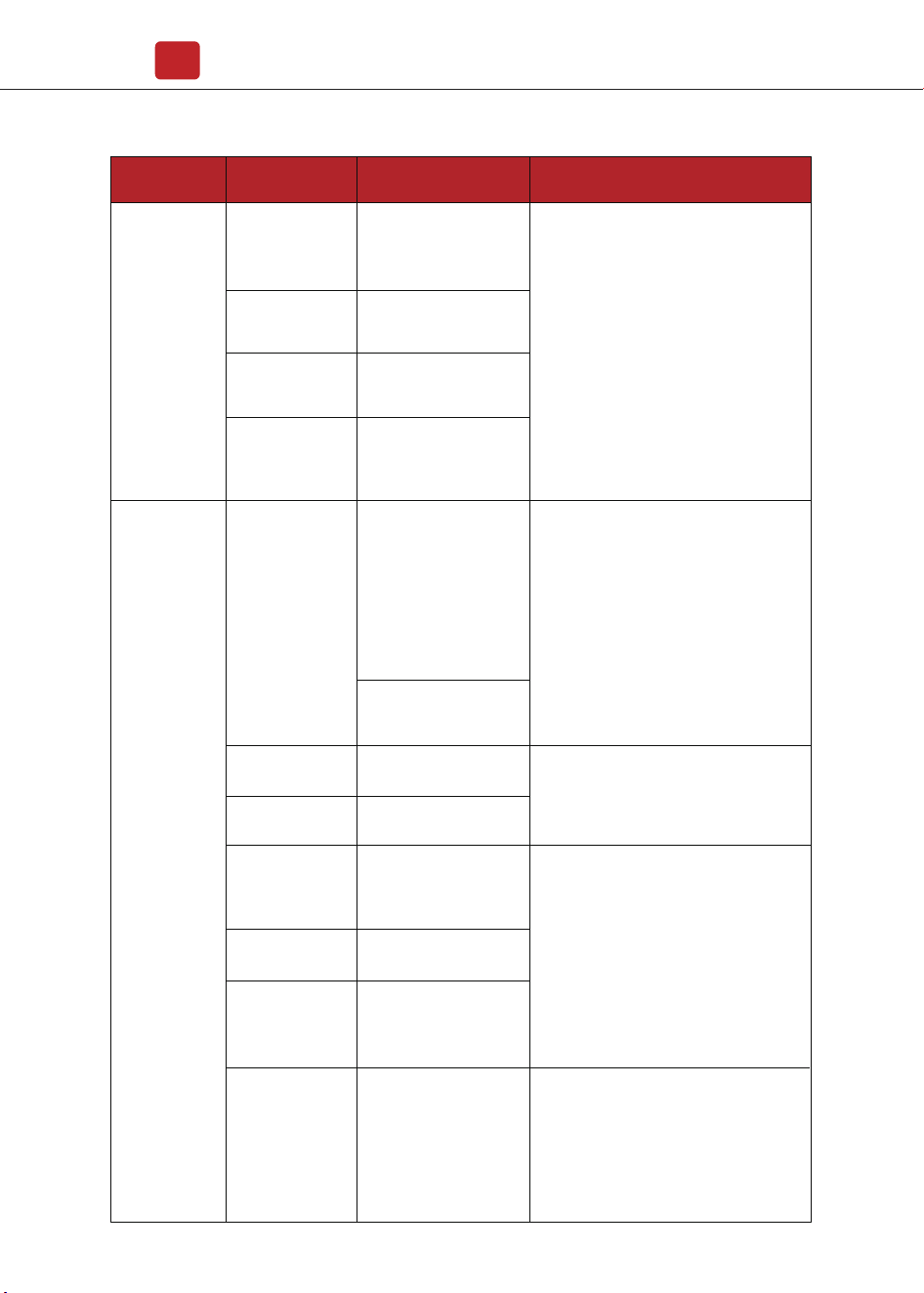
DC Fault
Type of Fault Name Description Recommend Solution
DC Offset Fault
The DC component of
grid-connected current is
too high that beyond the
reasonable range.
Bus Unbalance
Bus voltage unbalanced,
beyond the protection
range.
Bus High Volt
Bus voltage is too high
and beyond the
protection range.
Bus Low Fault
When inverter is running,
bus voltage is lower than
the normal value beyond
the protection range.
• Power off, then restart (Ref. Chapter6)
• If fault still occurs continuously and
frequently, please ask help for local
distributors.
Auto Test Fail
Automatic test failed.
No Utility
No continuous utility
• Power off the inverter to check the AC
connection, then restart.
• If fault still occurs continuously and
frequently, please ask help for local
distributors.
System Fault
The temperature of the
CPU is high that beyond
the protection range.
Over Temperature
The temperature of the
installation environment
is too high or too low,
beyond the reasonable
range.
The temperature of the
cooling device is high or
low thet beyond the
protection range.
• Improve or change the installation
environment to adjust the inverter
installation environment temperature to
normal range.
• Power off, then restart (Ref. Chapter6)
• If fault still occurs continuously and
frequently, please ask help for local
distributors.
Device Fault
Grounding is abnormal
or the ground wire is
disconnected.
• Check whether the ground wire of the
inverter is properly connected and the
ground impedance is too high, if it is,
make corrections.
• Power off, then restart (Ref. Chapter6)
• If fault still occurs continuously and
frequently, please ask help for local
distributors.distributors.
Consistent Fault
The detection results of
the two CPUs for the
same voltage and
frequency are different.
Self Lock
Inverter is locked at the
waiting interface.
Grid Volt AD
Grid voltage AD value
deviation is too high,
beyond the protection
range.
• Power off, then restart (Ref. Chapter6)
• If fault still occurs continuously and
frequently, please ask help for local
distributors.
Maintenance&Trouble Shooting
23
Specifications
24
Inner Warnning
Fan Fault
The fan can not work
when is started up.
• Check if there is objects which blocking
the fan rotation and remove it.
• Power off, then restart (Ref. Chapter6)
• If fault still occurs continuously and
frequently, please ask help for local
distributors.
Eeprom Fault
Eeprom abnormal
Type of Fault Name Description Recommend Solution
Main CPU to HMI
abnormal
Communication
Lose
CPU to Flash abnormal
CPU to Eeprom abnormal
Main CPU to auxiliary
abnormal
Specifications
25
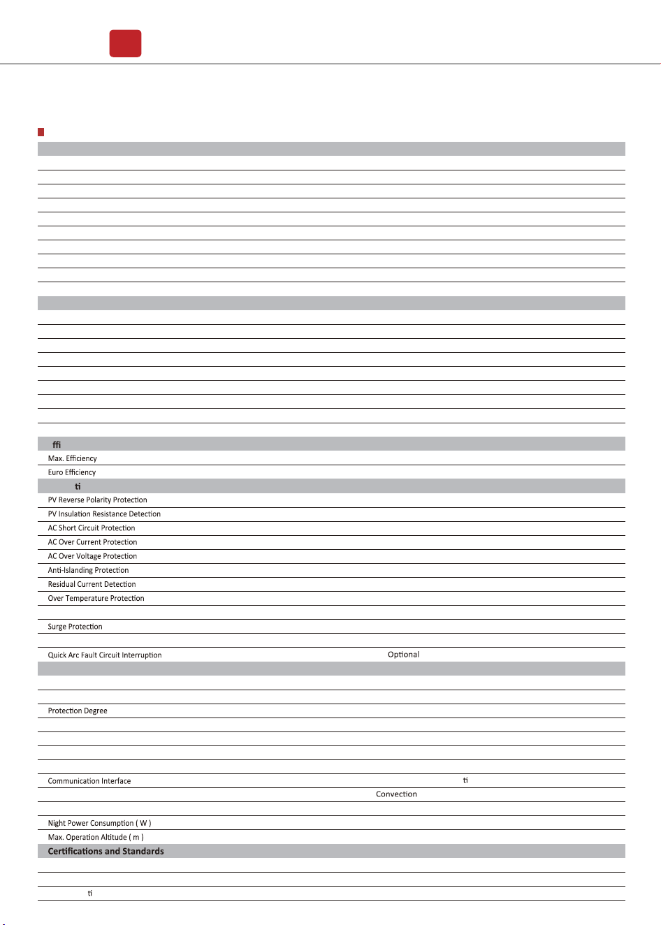
9. Specifications
IEEE1547, CSA C22, EN50549, VDE4105, VDE0126, RD1699, ABNT NBR16149 & 16150, AS4777.2, NB�T32004, IEC61727
RS485 � WiFi � Wire Ethernet � GPRS (op onal)
Aluminum
Transformerless
4000
10
<28
358 x 360 x 142
360
70
14 x 2
18 x 2
2�2
MC4
180Vac-276Vac (According to local standard)
45-55Hz�54-66Hz (According to local standard)
1 default (adjustable from 0.8 leading to 0.8 lagging)
L�N�PE, 220Vac, 230Vac, 240Vac
<3%
50�60
<1
IP65
0-100%
600
70-550
5500
5000
24
98.20%
97.90%
7000
600
70 -550
180-550
EN�IEC 61000-6-2, EN�IEC 61000-6-3, EN61000-3-2, EN61000-3-3, EN61000-3-11, EN61000-3-12
IEC 60068, UL1741, EN62109
220-550
6600
6000
28.7
98.20%
97.92%
8400
HNS5000TL
HNS6000TL
-25 to 60
Max. DC Power ( W )
Max. DC Voltage ( V )
MPPT Voltage Range ( V )
MPPT Full Power Voltage Range ( V )
Rated Input Voltage ( V )
Start-up Voltage ( V )
Max. Input Current ( A )
Max. Short Current ( A )
No. of MPP Tracker � No. of PV String
Input Connector Type
Max. Output Power ( VA )
Nominal Output Power ( W )
Max. Output Current ( A )
Nominal Output Voltage ( V )
Grid Voltage Range
Nominal Output Frequency ( Hz )
Grid Frequency Range
Output Power Factor
Output Current THD
PV Input Data
Protec
on
General Data
°C
Integrated DC switch
Dimensions (W x H x D, mm)
Weight ( kg )
Enclosure Material
Ambient Temperature Range ( )
Humidity Range
Topology
Cooling Concept
Noise Emission ( db )
EMC Standard
Safety Standard
Grid-connec
on
Technical Data
Smart IV Curve Scaning
AC Output Data
E
ciency
YES
YES
YES
YES
YES
YES
YES
YES
YES
Integrated (Type III)
YES