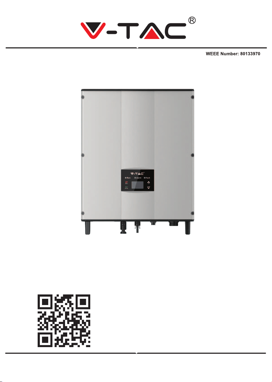
INSTRUCTION MANUAL
SOLAR INVERTER
IN CASE OF ANY QUERY/ISSUE WITH THE PRODUCT, PLEASE REACH OUT TO US AT: SUPPORT@V-TAC.EU
FOR MORE PRODUCTS RANGE, INQUIRY PLEASE CONTACT OUR DISTRIBUTOR OR NEAREST
DEALERS. V-TAC EUROPE LTD. BULGARIA, PLOVDIV 4000, BUL.L.KARAVELOW 9B
Thank you for selecting and buying V-TAC Product. V-TAC will serve you
the best. Please read these instructions carefully & keep this user manual
handy for future reference. If you have any another query, please contact
our dealer or local vendor from whom you have purchased the product.
They are trained and ready to serve you at the best.
INTRODUCTION
Multi-Language Manual QR CODE
Please scan the QR code to access the manual
in multiple languages.
WARNING
1. Please make sure to turn off the power before starting the installation.
2. Installation must be performed by a qualified electrician.
3. Proper grounding should be ensured throughout the installation.
Caution, risk of
electric shock.
This marking indicates that this
product should not be disposed
of with other household wastes.
20
PAP
SAFETY PRECAUTIONS
The series grid-tied solar inverters are designed and tested strictly in accordance with
relevant international safety standards. As an electrical and electronic device, all relevant
safety regulations must be strictly complied during installation, operation, and maintenance.
Incorrect use or misuse may result in:
• Injury to the life and personal safety of the operator or other people.
• Damage to the inverter or other property belonging to the operator or other people.
In order to avoid personal injury, damage to the inverter or other devices, please strictly
observe the following safety precautions.
This chapter mainly describes various warning symbols in operation manual and provides
safety instructions for the installation, operation, maintenance and use of the series grid-tied
solar inverters.
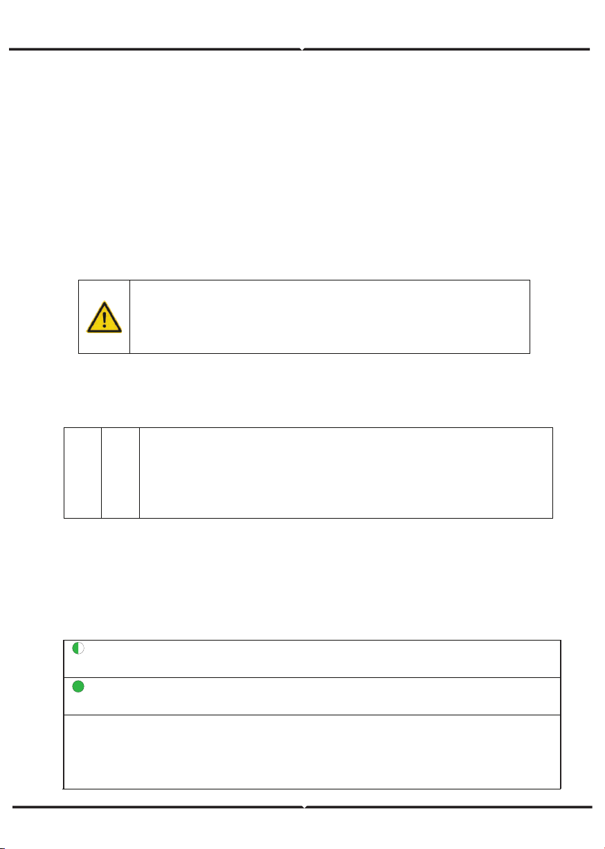
ICONS
This manual provides relevant information with icons to highlight the physical and property
safety of the user to avoid device damage and physical injury.
The icons used in this manual are listed below:
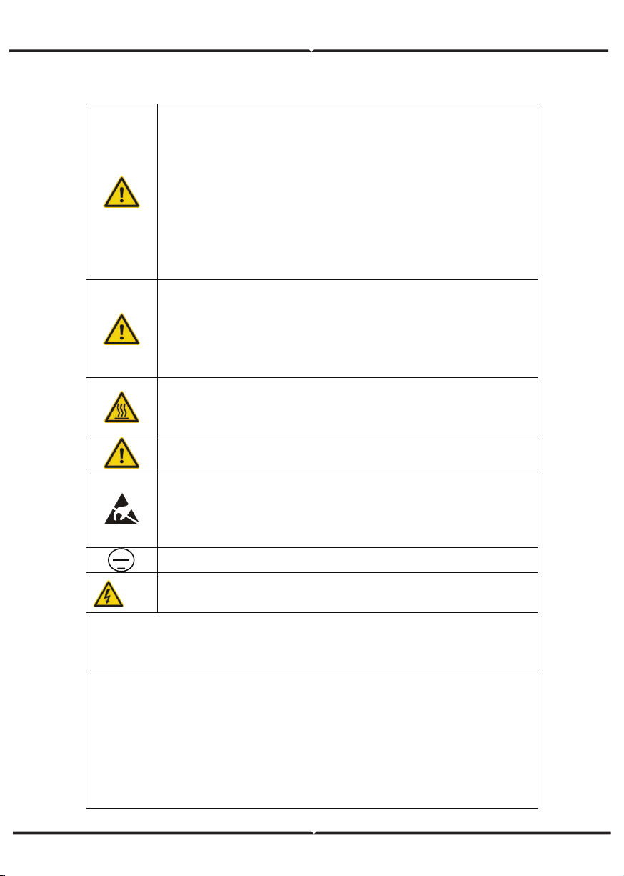
Icons Name Instruction Abbreviation
Danger
Danger
Serious physical injury or even death
may occur if not follow the relative
requirements
Warning
Warning
Physical injury or damage to the
devices may occur if not follow the
relative requirements
Do not
Electrostatic
sensitive
Damage may occur if not follow the
relative requirements
Hot sides
Hot sides
Sides of the device may become hot.
Do not touch.
Note Note
The procedures taken for ensuring
proper operation.
Note
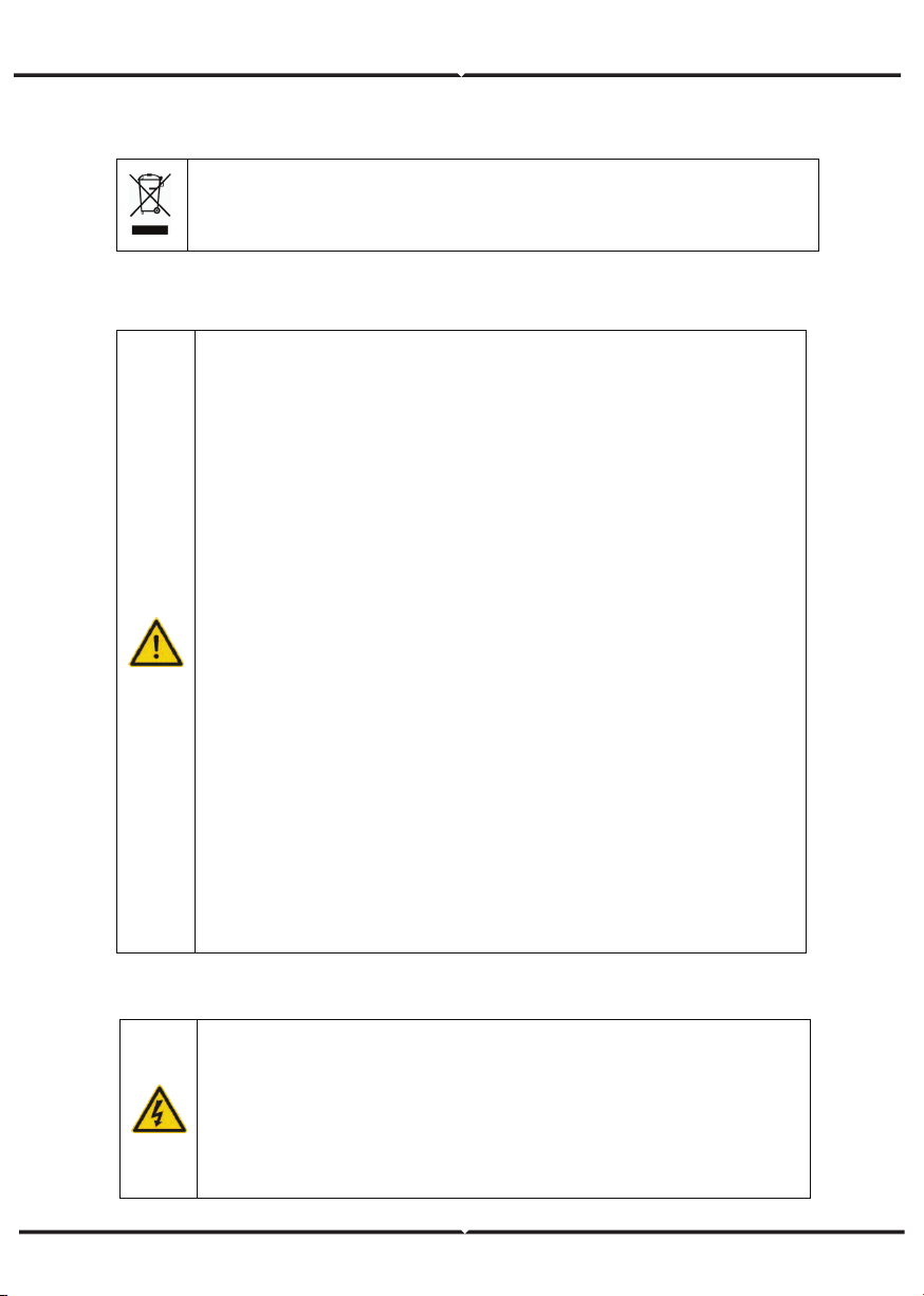
SAFETY GUIDELINES
After receiving this product, first ma ke sure that the product is well
packaged. If you have any questions, please contact the shipping
company or local distributor immediately.
Installation of PV inverters must be performed by professional
technician who has been specially trained, thoroughly read and familiar
with all the contents of this manual and familiar with the safety
requirements of the electrical system.
Do not carry out any wiring and inspection or changing components
when the power supply is applied.
Ensure that there is no electromagnetic interference from other
electrical and electronic equipment on the installation site.
Do not refit the inverter unauthorized.
All the electric installation needs to be compliance with the national or
local laws and standards.
The temperature of individual parts o r the enclosure of the inverter–
especially the heat sink may become hot in normal operation. There is a
danger of burning. Do not touch.
It must be reliably grounded before operation.
Do not open the cover of inverters unauthorized. The electrical parts
and components inside the inverter are electrostatic. Take
measurements to avoid electrostatic discharge during rel evant
operation.
The inverter must be reliably grounded.
Ensure that DC and AC side circuit breakers have been disconnected
and wait at least 5 minutes before wiring and checking.
Note: Technical personnel who can perform installation, wiring, commissioning,
maintenance, troubleshooting and replacement of the series grid-tied solar inverters
must meet the following requirements:
Operators need professional training.
Operators must read this manual completely and master the related safety precautions.
Operators need to be familiar with the relevant safety regulations for electrical systems.
Operators need to be fully familiar with the composition and operating principle of the
entire grid -tied photovoltaic power generation system and related standards of the
countries/regions in which the project is located.
Operators must wear personal protective equipment.
WHAT TO DO AFTER SCRAPPING
DELIVERY AND INSTALLATION
GRID-TIED OPERATION
Only qualified electricians are allowed to operate the inverter under the
permission of local power departments.
All electrical connections must meet the electrical standards of the
countries/regions in which the project is located.
Ensure reliable installation and electrical connection before operation.
Do not open the cover of inverter during operation or voltage is present.
Keep the package and unit complete, dry and clean during storage and
delivery.
Please remove and install the inverter with two or more people, because of
the inverter is heavy.
Remove and instal l the inverter with appropriate tools to ensure safe and
normal operation and avoid physical injury or death. The people also need
mechanical protective measures, such as protective shoes and work clothes.
Only qualified electricians are allowed to install the inverter.
Do not put and install the inverter on or close to combustible materials.
Keep the installation site away from children and other public places.
Remove the m etal jewelry such as ring and bracelet before installation and
electrical connection to avoid electric shock.
Do cover solar modules with light-tight materials before electrical connection.
Exposed to sunlight, solar modules will output dangerous voltage.
The inverter input voltage cannot exceed the maximum input voltage;
otherwise inverter damage may occur.
The positive and negative pole of solar module s cannot be grounded,
otherwise irrecoverable damage may occur.
Ensure the proper grounding of the inverter, otherwise, improper connection
or no grounding may cause stop of the in verter.
Ensure reliable installation and electrical connection.
Do not dispose of the inverter together with household waste. The user has
the responsibility and obligation to send it to the designated organization for
recycling and disposal.
APPLICATION
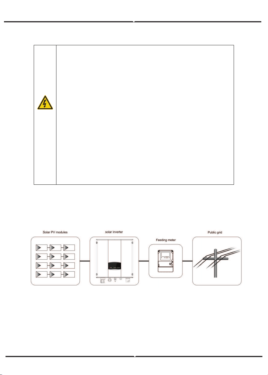
The photovoltaic grid-tied power generation system consists of solar modules, grid-tied
inverter, metering devices and public grid.
Grid-tied solar inverter is the core of photovoltaic power generation system. The solar energy
can be converted into DC electric energy through solar modules and then be changed into
sinusoidal AC energy which has the same frequency and phase with the public grid by
grid-tied solar inverters, and then be fed to the grid.
The series grid-tied solar inverters are only applied in solar grid-tied power generation
system and its DC input are only composed of crystalline silicon solar modules whose
negative and positive poles are not grounded.
MAINTENANCE AND INSPECTION
SOLAR GRID-TIED POWER GENERATION SYSTEM
Only qualified electricians are allowed to perform the mainte-
nance, inspection, and components replacement of the inverter.
Contact with the local dealer or supplier for maintenance.
In order to avoid irrelevant personnel from entering the mainte-
nance area during maintenance, temporary warning labels must be
placed to warn non-professionals to enter or use fence for isolation.
Firstly disconnect all power supplies of the grid to the inverter
before any maintenance, and then disconnect the DC breakers and
wait for at least 5 minutes until the inverter is discharged before
maintenance.
Please follow electrostatic protection norms and take correct
protective measures because of the electrostatic sensitive circuits
and devices in the inverter.
Do not use parts and components not provided by our company
during maintenance.
Restart the inverter after settling the fault and problem which may
affect the safety and performance of the inverter.
Do not get close to or touch any metal conductive part of the grid
or inverter, otherwise electric shock, physical injury or death and fire
may occur. Please do not ignore the warning icons and instructions
with “electric shock”.
Figure 1 Application of the series grid-tied solar inverters
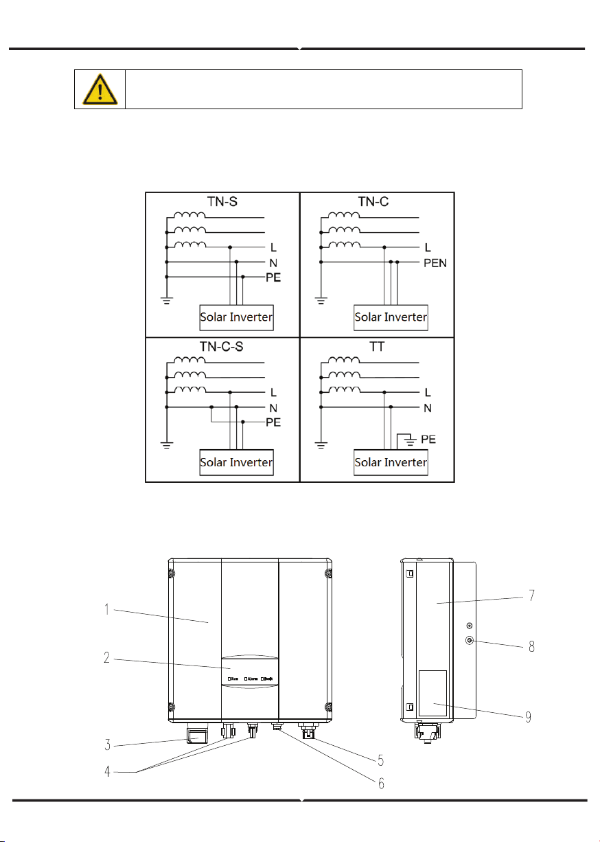
The series grid-tied solar inverters support TN-S, TN-C, TN-C-S and TT grid connection.
When applied to the TT connection, the N-to-PE voltage should be less than 30V.
SAFETY GUIDELINES
PRODUCT APPEARANCE
The recommended solar modules need to comply with IEC61730 Class A
standard.
Figure 3 Products appearance
PARTS INSTRUCTION
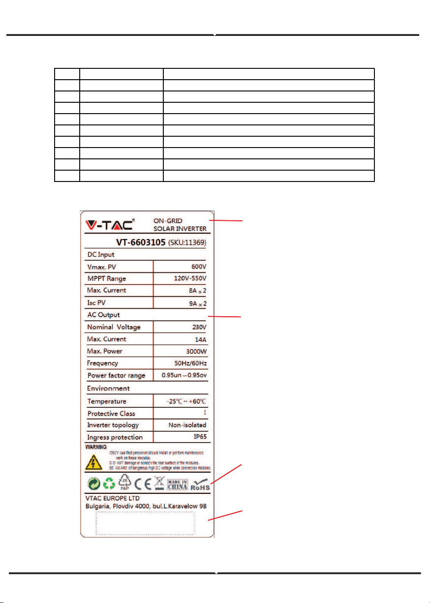
NAMEPLATE
Figure 4 Inverter nameplate
1. Trademark and product type
2.Model and important technical
parameters
4.Serial number, company name
and country of origin.
3.Certification system of the
inverter confirming
No. Name Instruction
1
Cover
2 LED display panel LED indicators
3 DC switch On –off o f the DC input (o ptional)
4 DC input port For the co nnectio n of so lar modules
5 AC terminal For the co nnectio n of A C output
6 Communicatio n po rt RS485 and EXT communicatio n po rt
7 Coo ling chamber
8 Radiator
9 Name plate For rated parameters and safety precautio ns o f the inverter
PRODUCTS MODULES
Table of the grid-tied solar inverter
Product name Model
Rated output
power
Single-phase (L, N, PE)
Single-phase grid-tied solar inverter
Single-phase grid-tied solar inverter
3KW-2M 3000
5KW-2M 4600
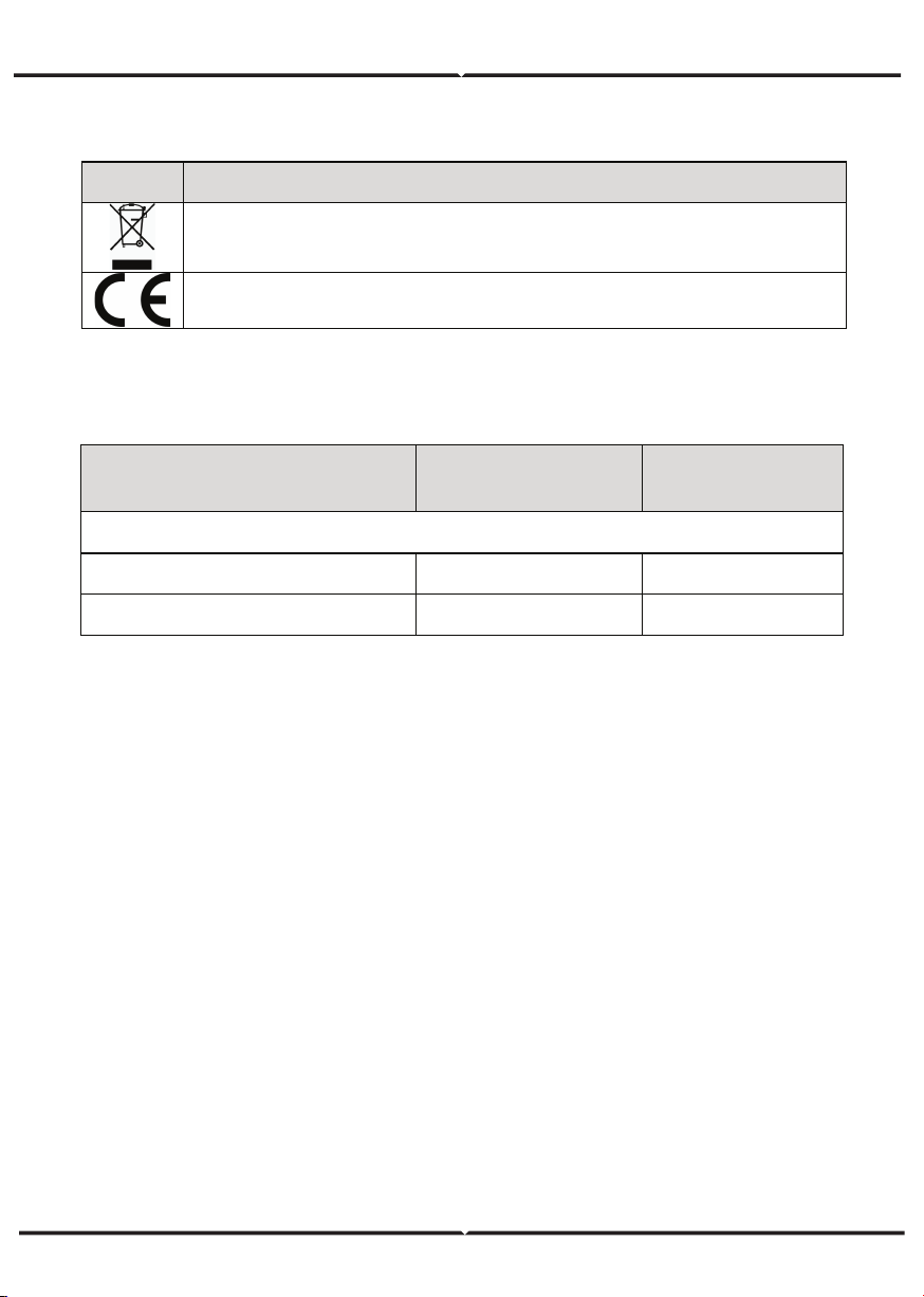
ICONS CERTIFICATION
Icons Instruction
CE certification mark. The inverter complies with the CE directive.
EU WEEE mark. Cannot dispose of the inverter as household waste.
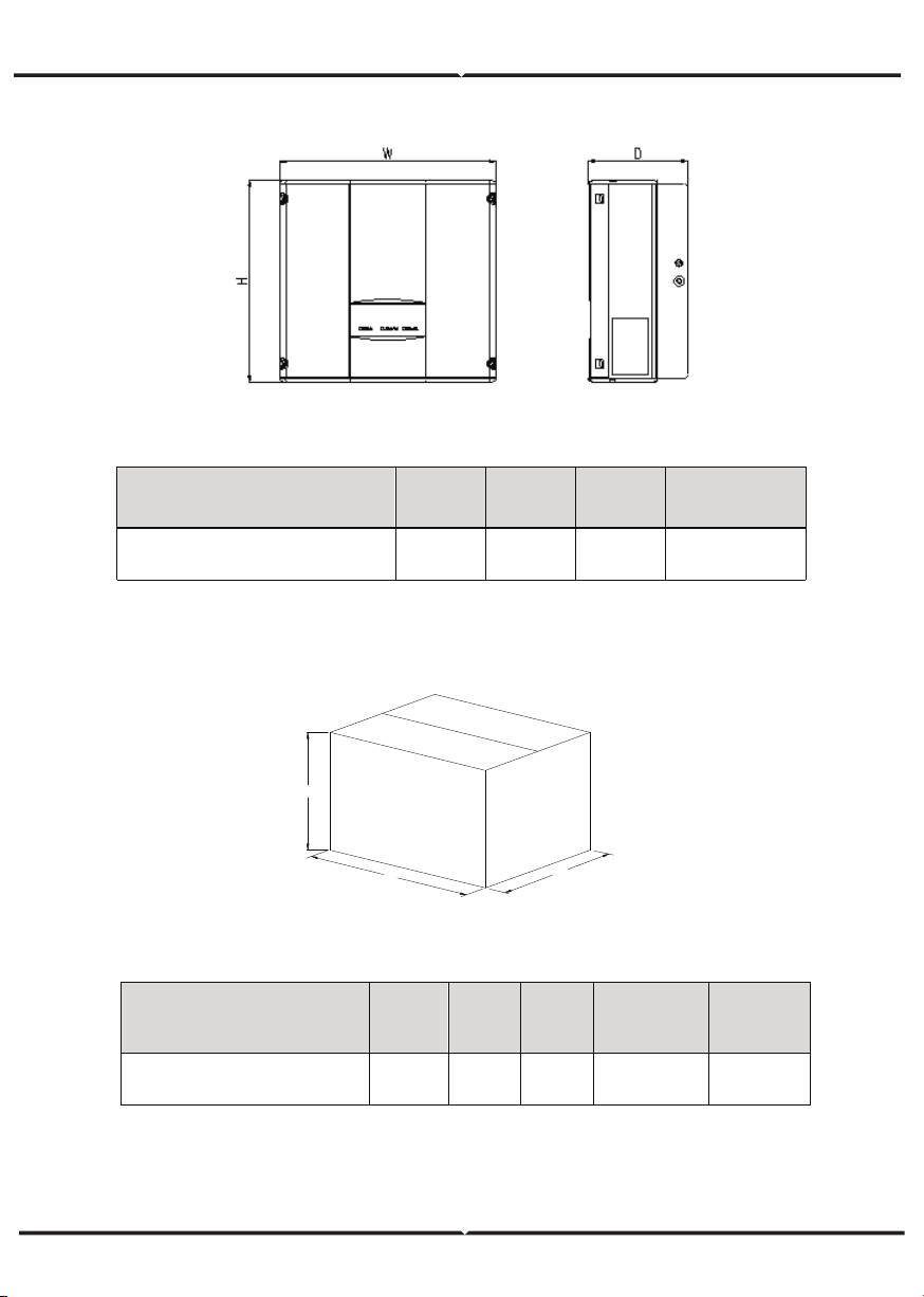
Model H (mm)
W
(mm)
D (mm)
Net weight
(kg)
3KW-2M / 5kW-2M
420 360 150 17
D
DIMENSIONS AND WEIGHT
Figure 5 Inverter dimensions
Table of inverter dimension and net weight
Figure 6 Paper packages dimension
Table of packages dimension and gross weight
W
H
Model
H
(mm)
W
(mm)
D
(mm)
Gross
weight
(kg)
Packagin
g
Material
3KW-2M / 5kW-2M
573 480 284 19 Paper
STORAGE
If the inverter is not put into use immediately, the storage of inverter should meet the
following requirements:
• Do not remove the outer packing.
• The inverter needs to be stored in a clean and dry place, and prevent the erosion of
dust and water vapor.
• The storage temperature should be kept at -40°C~+70°C, and the relative humidity
should be kept at 5%RH~95%RH.
• The stacking of inverters is recommended to be placed according to the number of
stacking layers in the original shipment. Place the inverter carefully during stacking to
avoid personal injury or equipment damage caused by the falling of equipment.
• Keep away from chemically corrosive substances that may corrode the inverter.
• Periodic inspections are required. If damages are found by worms and rats, or packages
are found to be damaged, the packaging materials must be replaced in time.
• After long-term storage, inverters need to be inspected and tested by qualified person-
nel before put into use.
INSTALLATION
This chapter describes how to install the inverter and connect it to the grid-tied solar
system (including the connection between solar modules, public grid and inverter).
Read this chapter carefully and ensure all installation requirements are met before
installation. Only qualified electricians are allowed to install the inverter.
UNPACKING INSPECTION
The inverter has been thoroughly tested and rigorously checked before delivery, but
damage may still occur during transportation. Before unpacking, check carefully whether
the product information in the order is consistent with that on the nameplate of the
package box and whether the product package is intact. If any damage is detected,
please contact the shipping company or the supplier directly. Please also provide photos
of the damage to get our fastest and best service.
Put the inverter into the package if not used and protect it from humidity and dust.
Check as following after unpacking:
(1) Ensure no damage to the inverter unit.
(2) Ensure the operation manual, port and installation accessories in the package.
(3) Ensure no damage or loss to the items in the package.
(4) Ensure the information of the order is the same as that of the name plate.
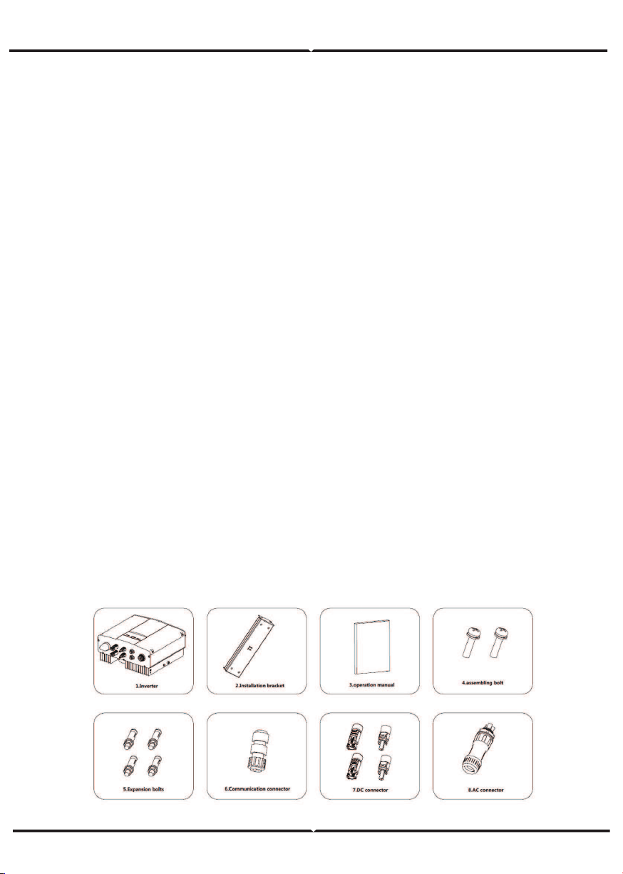
(5) The standard delivery list is shown as below.
Single-phase inverter packing list:
Figure 7 Single-phase inverter packing list
INSTALLATION PLACE
Select installation place based on the following considerations:
(1) The height of the installation position should ensure that the line of sight is at the same
level as the LCD for viewing the parameters of inverter conveniently.
(2) Select a well ventilated place sheltered from direct sun radiation and rain.
(3) Allow sufficient space around the inverter to enable easy installation and removal from
the mounting surface and air convection. (See Figure 8).
(4) The ambient temperature of installation should be -25°C~60°C
(5) The installation site should be away from electronic devices which can generate strong
electromagnetic interference.
(6) The inverter needs to be installed on a firm and sturdy surface, such as wall and metal
bracket and so on.
(7) The installation surface should be perpendicular to the horizontal line. (See Figure 9)
(8) The installation should ensure that the inverter is reliably grounded, and the material of
grounded metal conductor should be consistent with the metal material reserved for the
grounding of the inverter.
BEFORE INSTALLATION
Installation tools
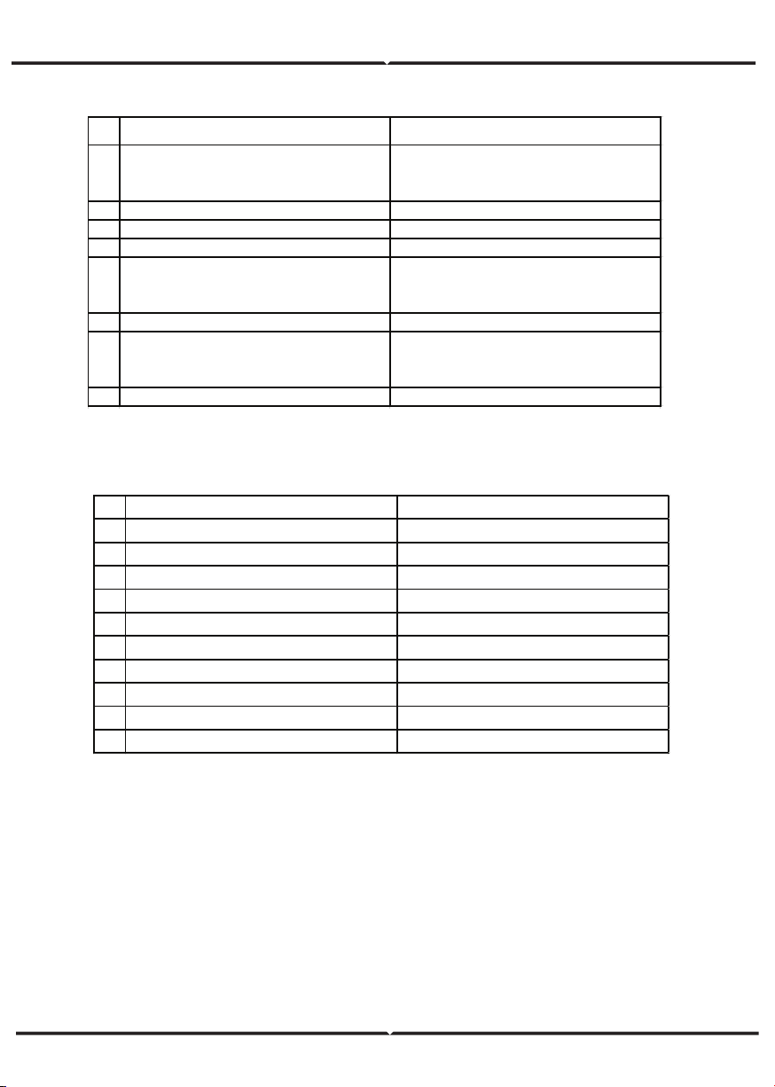
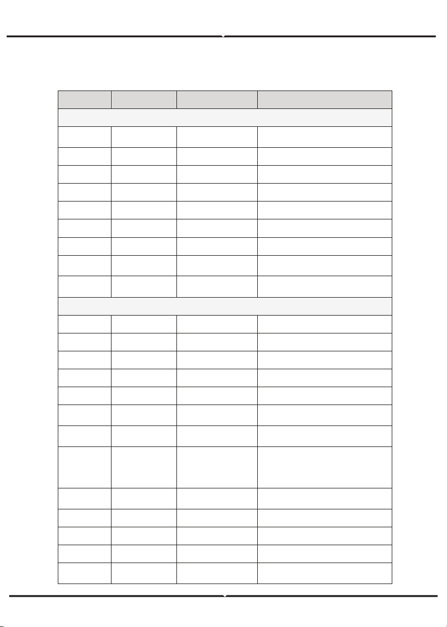
Table of detailed delivery list of single-phase inverter
NO NAME QUANTITY
1
3KW-2M / 5KW-2M
1
2 Installatio n bracket 1
3
Operation manual 1
4 Bolt M 5*20 2
5 Expansion bo lts M 6*60
3KW-2M / 5KW-2M
6 Communication co nnecto r 1
7 DC connector
3KW-2M / 5KW-2M:2 pairs
8 AC connector 1
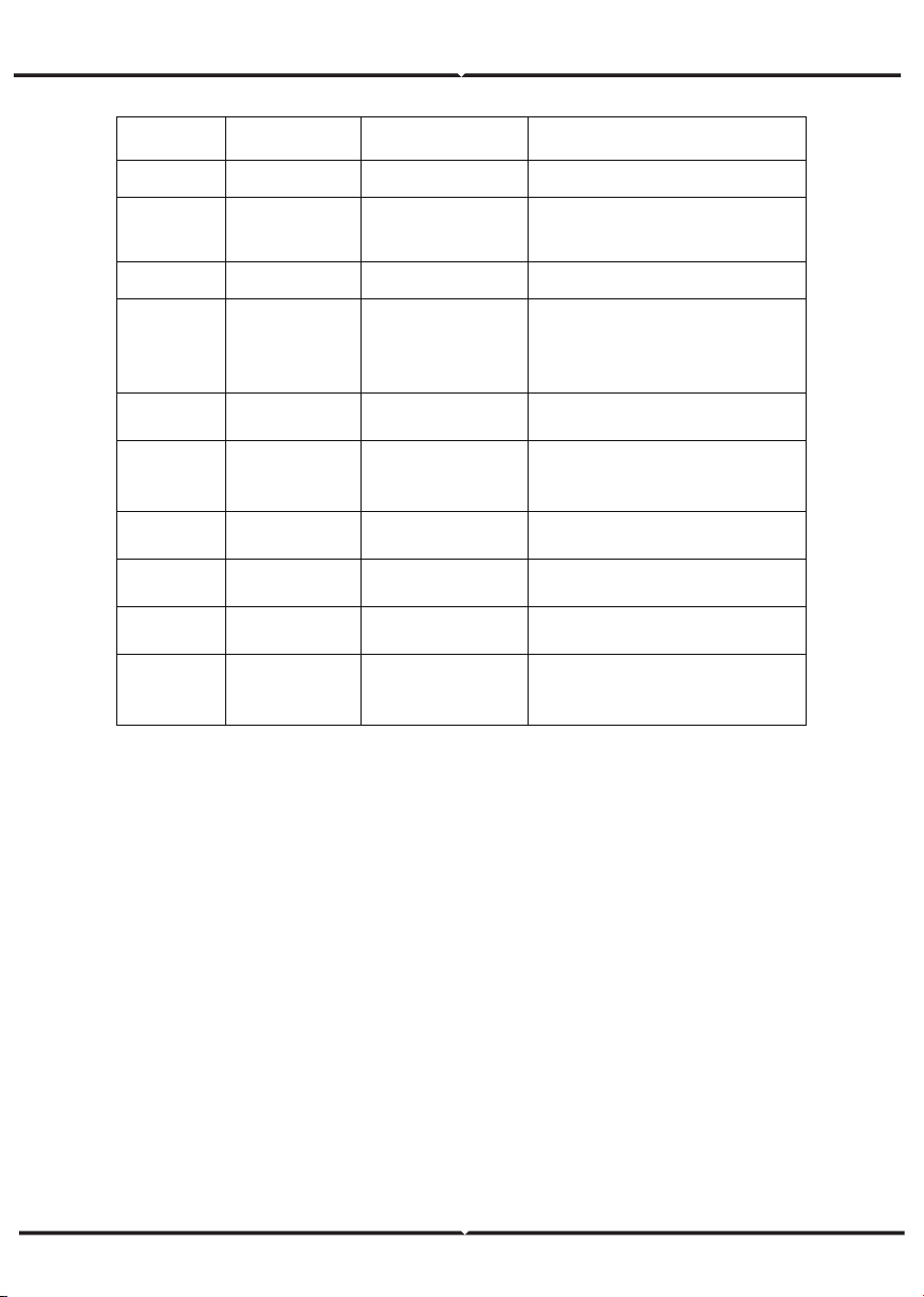
Table of tools list
NO INSTALLATION TOOLS INSTRUCTION
1 M arking pen M ark the installation hole
2 Electrodrill Drill in the bracket o r wall
3 Hammer Hammer on the expansio n bo lts
4 M o nkey wrench Fix the installatio n bracket
5 Allen driver Fasten the screws, remo ve and install A C wiring box
6 Straight screwdriver For AC wiring
7 M egger M easuring insulation performance and impedance
8 M ultimeter Check the circuit and A C and DC vo ltage
9 Electric iro n Weld co mmunications cable
10 Wire crimper Crimp DC terminals
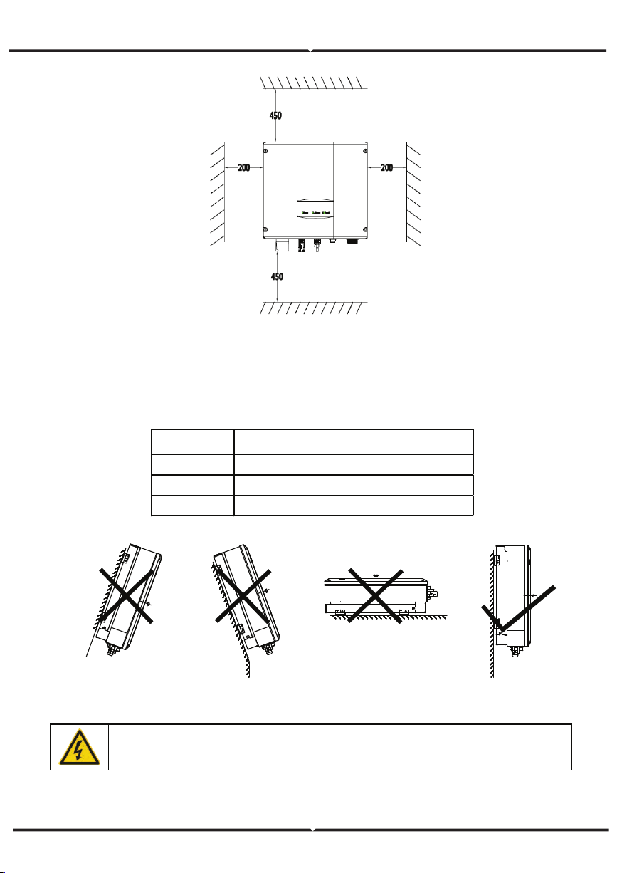
Figure 8 Installation space
Figure 9 Installation position
Ensure there is sufficient space for heat-releasing. In generally, below space requirement
should be met:
Table of detailed installation space
M inimum clearance
Lateral 200mm
Top 450mm
Bottom 450mm
Do not open the cover of the inverter or replace any part as incomplete
inverter may cause electric shock and damag e the device during operation.
CABLE SPECIFICATION
In order to regulate and compatible with the inverter AC/DC connector or terminal block
specifications, below requirements on the AC/DC cable connected to corresponding inverter
should be fulfilled:
MINIATURE CIRCUIT BREAKERS
In order to ensure safe operation of the inverter and circuits, it is recommended to
configure corresponding micro breaker or fuse on the DC input side and AC output side
of the inverter. The below table is the requirements for recommended micro breaker:
MECHANICAL INSTALLATION
The material for fixing the inverter and the installation mode vary with the different
installation sites. It is recommended to install the inverter vertically to the firm wall or
metal bracket. Here we take wall installation as an example to introduce the installation
matters of the inverter.
As shown in the Fig 10, the overall installation of the inverter should be vertical to the
horizontal surface.
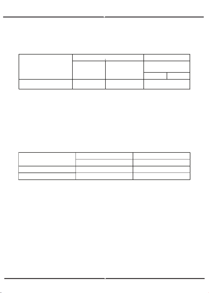
Table of cable specifications
Table of specifications of micro breaker
DC input AC o utput
Recommended DC breakers Recommended AC breakers
3KW-2M
DC500V, C16A , 2P
AC240V, C20A, 2P
5KW-2M
DC500V, C20A, 2P A C240V, C32A, 2P
M o del
L N/PE
3kW-2M / 5kW-2M
4 4
6
M o del
DC side AC side
M in cro ss-
sectional area
mm²(length≤50m)
M in cross sectional
area mm²
(Length>50m)
M ini cro ss-sectional
area mm²
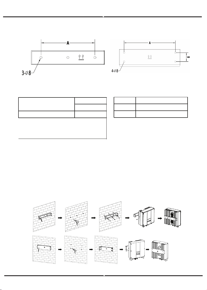
INSTALLATION STEPS:
(1) Firstly, take down the installation bracket from the package.
(2) Place the bracket at the appropriate height and position on the wall. Mark the punching
position according to the fixing hole. Drill holes of 70mm deep and install the expansion
screw. Fix the bracket on the expansion bolt according to the arrow instruction. Ensure the
installation is firm enough, the tightening torque is 8Nm.
(3) Lift the inverter to suspend it on the installation bracket through M8 hex socket cap
screws.
(4) Finally, fasten the inverter and the bracket with M5 screws and tighten the screws to 2
Nm. For firm installation, the operators cannot release the device until the inverter is
installed on the bracket firmly.
Table of size of installation bracket Table of instruction of installation bracket
Figure 10 Installation bracket
of 0.75~3KW inverter
Figure 11 Installation bracket
of 4~6KW inverter
INSTALLATION OF SINGLE-PHASE INVERTER
No. Structure instructio n
1 Installation holeΦ 8
2 Assembling bo lt ho le M 5
Installation ho le
A(mm)*B(mm)
3KW-2M / 5KW-2M
260*45
M o del
Figure 12 Installation of inverter
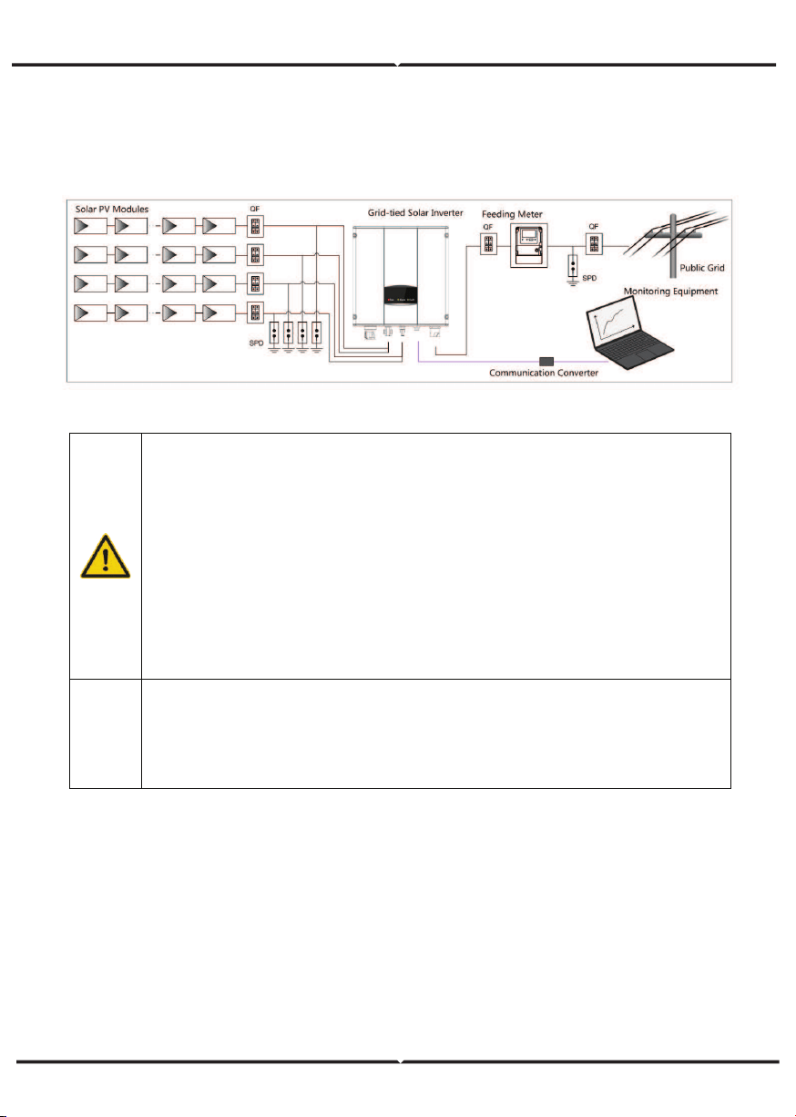
WIRING INSTALLATION
This section describes the electrical connection related content and related safety
precautions. Figure 13 is the schematic diagram of the photovoltaic grid-connected
system.
Figure 13 PV grid-connected system diagram
Electrical connection must be carried out by professional technicians as wrong
operation may cause damage to the device, physical injuries or even death
during system operation.
All the electrical installation must conform to the national and local electrical
safety regulations.
Ensure all the cables are installed firmly according to the specified safety
requirements and free from any damage.
It is not allowed to close the AC and DC breakers before the inverter is
electrically connected.
Note
Read and follow the instructions provided in this section . Strictly follow the
requirements when operating.
Always note the rated voltage and current defined in this manual. Never exceed
the limits.
WIRING INSTALLATION
Connection steps:
(1) Lighting, short-circuit and other protection measures which meet the local electrical
safety laws and regulations are needed before the AC connection.
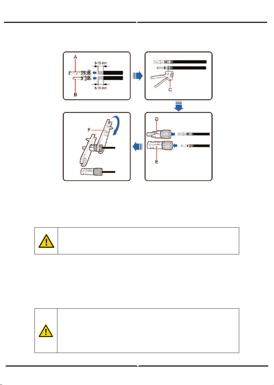
(2) Connect the output cables of solar modules to the DC connector of inverter as Figure
4.8 shows. Loose the nut of connector and remove the isolation layer of the DC cable for
about 8-10mm. Insert the conductor part into the appropriate position of the connector,
crimp the MC4 DC terminal of the inverter and tighten the nut with a torque of 2.5-3Nm.
The wiring of negative pole is the same as that of the positive pole. Ensure the poles of
solar modules are well connected with the connectors;
Figure 14 Connection between DC connector and solar modules
PV strings can be connected to inverter only after protection measures
which conform to local electrical regulations are taken and the technical
parameters in this manual are fulfilled.
The PV string connected to the series inverter must adopt the DC connector
configured especially for the inverter, do not use other connection devices
without authorization from our company, otherwise damage to the device,
unstable operation or fire may occur and our company will not undertake
quality assurance or assume any direct or joint liability thereof.
AC CONNECTION
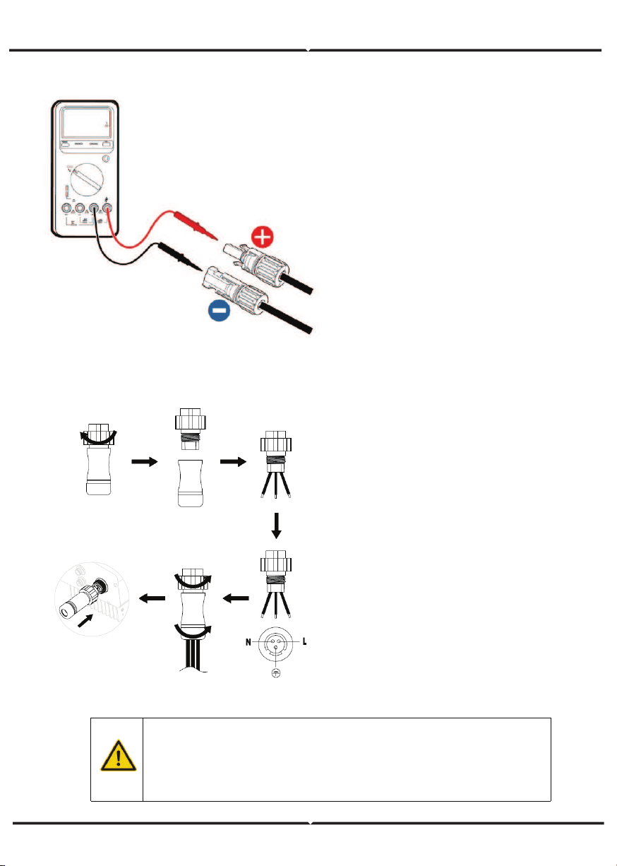
(3) After the DC connector is connected,
use a multimeter to measure the
voltage of the DC input string, verify the
polarity of the DC input cable, and
ensure that the voltage of each string is
within the allowable range of the
inverter, as shown in Figure 15
(4) Connect the DC connector with the
inverter and ensure tightly-fastened;
(5) When removing the DC connector
from the inverter, insert the head of the
straight screwdriver into the raised hole
in the middle of the connector, and force
the movable end of the connector to
exit.
AC connection steps of single-phase
inverter:
(1) Before connecting the single-phase
AC grid cable to the inverter, take
lightning and short circuit protection
measures in accordance with the local
electrical safety codes;
(2) As shown in Figure 16, connect and
fasten L, N and PE conductors of the
single-phase AC grid to AC terminal and
tighten to 0.5 Nm. Assemble the AC
terminal and tighten to 2.5-3 Nm, then
connect the terminal to the AC port of
the inverter.
(3) Connect the DC output cable of the
PV module to the DC connector which
provided by our company, and then
connect the DC connector to the DC
terminal of the inverter.
Figure 15 DC input voltage measuring
Figure 16 AC connection of single-phase inverter
• Only qualified cables under the local electrical safety laws and
regulations and comply with the technical parameters of this
manual are allowed to connect to the inverter.
• Only with the permission of the local electric power company can
the inverter be connected to the utility grid.
OPERATION
INSPECTION BEFORE OPERATION
GRID-TIED OPERATION
The following items must be checked strictly before running the PV grid-connected
inverter (including but not limited to):
(1) Ensure the installation site meet the requirement mentioned in installation pace for
easy installation, removing, operation and maintenance;
(2) Ensure the mechanical installation meet the requirement mentioned in table of
installation pace;
(3) Ensure the electrical installation meet the requirement mentioned in table of cable
specifications;
(4) Ensure all switches are “off”;
(5) Ensure the open circuit voltage of the PV module complies with the DC side parameter
requirements(in the appendix) of inverter;
(6) Ensure all electrical safety precautions are clearly-identified on the installation site.
Please start the inverter as follows:
(1) Ensure the requirements mentioned in inspection before operation are met;
(2) Switch on the breakers at the AC side;
(3) Switch on the integrated DC switch;
(4) Switch on the switch on the DC side;
(5) Observe the LED indicator state of the inverter and the information displayed by LCD.
Refer to chapter 6 for LED state indicator and LCD display information.
In order to ensure a safe, normal and stable operation of the PV power
generation system, all the newly installed, renovated and repaired PV grid -
connected power generation system and its grid -connected inverter must
undergo inspection before running.
Start the inverter according to below steps to achieve grid-connected operation of the
inverter:
Note Note
Must to select the country to set grid-connected standard during the initial
operation of the inverter
Keep the power-on state of the inverter for at least 30 minutes, and complete
the charging of built-in clock battery of the inverter to ensure the clock can run
normally!
Run
Green indicator flickers, other indicators are off: Inverter is powered on and
under self-inspection, wait for enough light to fulfill grid -connected condition;
Run
Green indicator on, others off : The inverter is in power generation after self-
inspection----successful commissioning.
“Warn” or “Fault” indicator is on or flickers: inverter is powered on but system fault
occur. Refer to LCD screen to check the fault code in LCD display, stop the inverter as per
STOPPING, and rule out faults according to TROUBLESHOOTING. After all the faults are
removed, repeat the operations
STOPPING
When it is necessary to carry out power-off maintenance, inspection and fault elimination
on the inverter, stop the inverter according to the following steps:
(1) Disconnect the breaker on inverter public grid AC side;
(2) Disconnect the integrated DC switch of the inverter;
(3) Disconnect the circuit switch on PV string DC input side;
(4) Wait for at least 5 minutes until the internal parts of the inverter are fully discharged,
and complete the stop operation.
DAILY MAINTENANCE
In solar PV grid-connected power generation system, the series grid-connected solar
inverter can realize grid-connected power generation and stop/start operations automati-
cally day and light in whatever seasons. In order to safeguard and prolong the service life
of the inverter, it is necessary to carry out daily maintenance and inspection on the
inverter besides using the inverter strictly according to this manual.
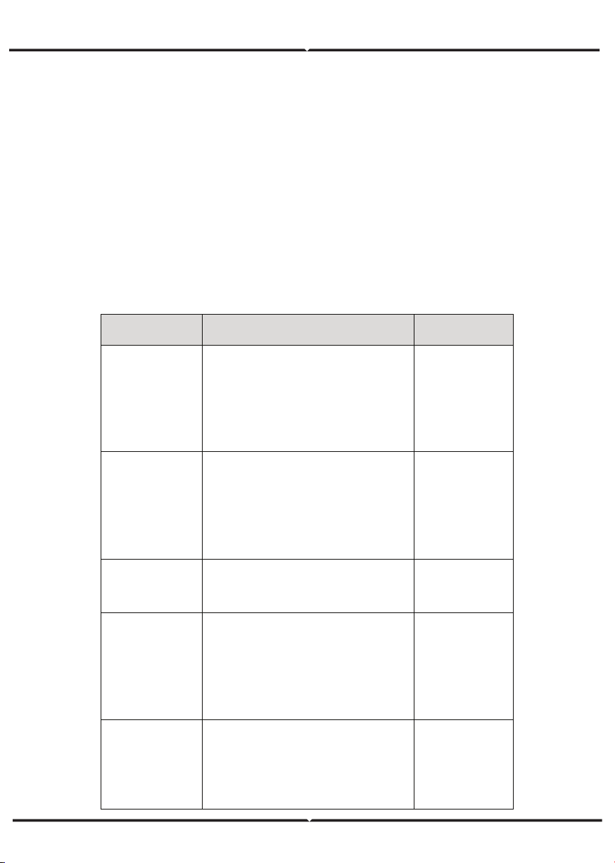
REGULAR MAINTENANCE
Maintenance
contents
Maintenance methods
Maintenance
cycle
Store the operation
data
Use real-time monitoring software to read
inverter running data, regularly back up all
inverter running data and stats. Check the
monitoring software and inverter LCD
screen to make sure the parameters are set
correctly.
Once each quarter
Check inverter
operation status
Check to make sure the inverter installation
is solid, no damage or def ormation. When
inverter running, check to make sure the
sound and variables are normal. When
inverter running, use thermal imager to
check whether the case cooling is normal.
Every six months
Clean the inverter
Check the ambient humidity and dust
around inverter, clean the inverter when
necessary.
Every six months
Check electrical
connection
Check whether system cable connection
and inverter terminal block are loosened, if
yes, secure them again in the manner
specified in installation. Che
ck whether the
cable is damaged, and whether the cable
skin touched by the metal surface is cut.
Every six months
Check the security
features
Check the inverter LCD and stop function of
the system. Simulate stop operation and
check the stop signal communication. Check
the warning marks and replace them if
necessary.
Every six months
MAINTENANCE GUIDE
Clean the inverter
Cleaning procedure is as follows:
(1) Disconnect the input and output switches.
(2) Wait ten minutes.
(3) Use a soft brush or a vacuum cleaner to clean the surface and the inlet and outlet of
the inverter.
(4) Repeat inspection before operation - operating content.
(5) Restart the inverter.
DISPLAY PANEL
This chapter describes the panel displaying and how to operate on the panel, which
involves the LCD display, LED indicators and operation panel.
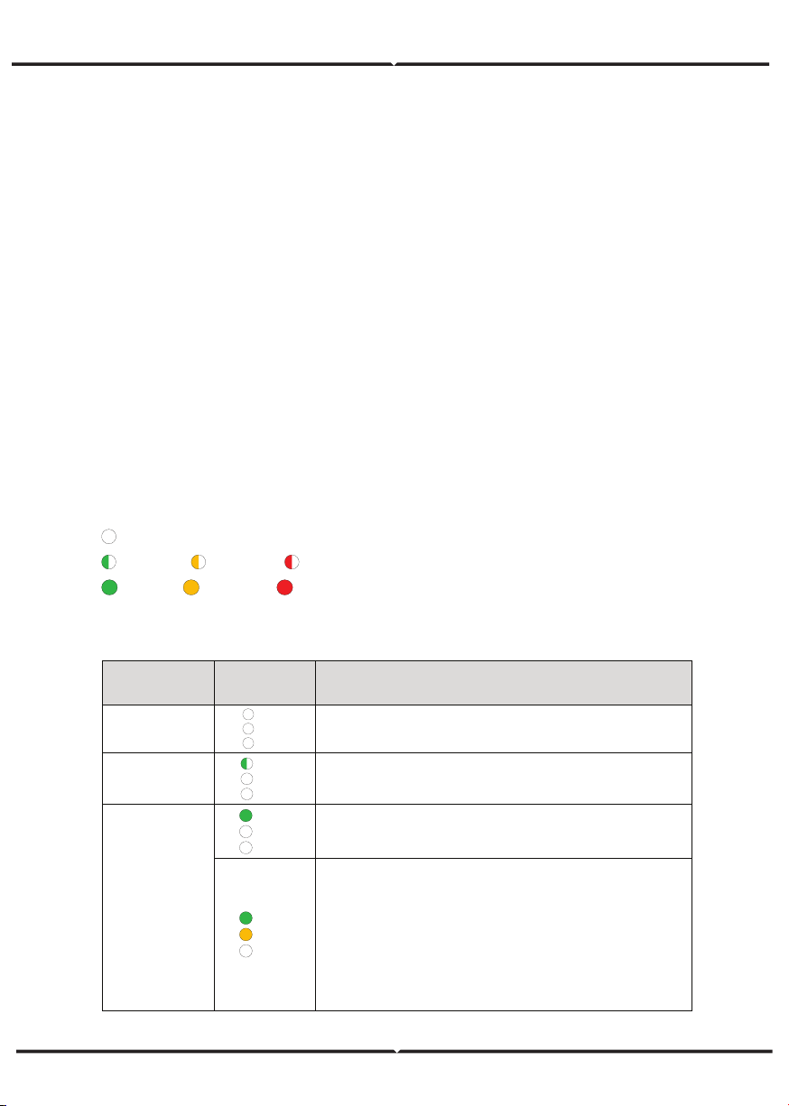
LED INDICATORS
There are three LED indicators on the panel:
(1) “Run”, operation indicator, green;
(2) “Warn” recoverable fault indicator, yellow;
(3) “Fault”, unrecoverable fault indicator, red.
The inverter state includes 6 states of stand-by, self-inspection, power generation,
recoverable fault and unrecoverable fault; LED indicators are on, off and blinking. Please
refer to the table below for detailed state of inverter and LED indicators state.
“ ”: LED indicator is off;
“
” (green), “ ” (yellow), “ ” (red): LED indicator is blinking at every 0.25S or 0.5S;
“ (Green), “ ” (yellow), “ ” (red): LED indicator is on.
Table of inverter state and LED indicators
Inverter
state
LED
indicators
Description
Stand-by
Run
Warn
Fault
No power on. All indicators off.
Self-
inspection
Run
Warn
Fault
Green indicator blinks in every 0.25s, others off. Power
on and ready for self-inspection
Power
generation
Run
Warn
Fault
Green indicator keeps on, others off.
Grid-tied power generation.
Run
Warn
Fault
(1) Grid-tied power generation, but clock fault (A 007);
(2) Grid-tied power generation, but DC input fault
(A001 or E001);
(3) Grid-tied power generation,but fan fault(E006 or
E012);
Green and yellow indicator keeps on, others off.
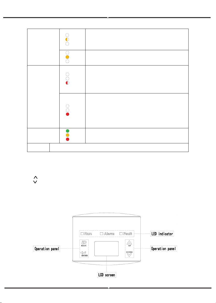
OPERATION PANEL
There are 4 buttons on the panel:
(1) “ESC”, exit and return ;
(2) “ ”, back to the front page and data increasing;
(3) “ ”,to the next page and data decreasing;
(4) “ENT”, enter.
The machine can be turned on and off by pressing the buttons: press "ESC" and
"ENT"(about 3 seconds) at the same time, and then the quick start-up and stop is
available.
LCD SCREEN
Recoverable
fault
Run
Warn
Fault
Inverter stand-by. The public grid fault(A001, A003,
A004, A005or A006);
Yellow indicator blinks in every 0.5s, others off
Run
Warn
Fault
(1) Inverter stand-by. Temperature abnormal(E006);
(2) Inverter stand-by. DC input fault (E001);
Yellow indicator keeps on, others off
Unrecoverable
fault
Run
Warn
Fault
Hardware or software fault (E003, E004, E005, E008,
E009, E011, E013 or E015). De-couple the inverter
from the system before maintenance.
Red indicator blinks in every 0.5s, others off
Run
Warn
Fault
Current-leakage or unqualified output power energy of
the inverter (E007, E010, E014, E017, E018 or E020).
De-couple the inverter from the system before
maintenance.
Red indicator keeps on, others off
Artificial turned
off
Run
Warn
Fault
Stop after the communication or panel command. All
indicators are on.
Note
Please refer to chapter 6 and 8 for detailed fault information and
troubleshooting.
Figure 17 Operation panel
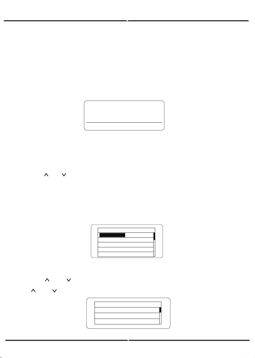
MONITORING PARAMETERS
Press “ ” and “ ” in the main interface to select “Monit Param”, and then press “ENT”
to view the parameters which is shown in Figure 20. Go the front or next page through
“ ” and “ ” and return through “ESC”.
All information is displayed on the LCD screen. The background illumination of LCD
screen will go out to save power if there is not button operation in 15 seconds. But it
can be activated by pressing any button. Press “ENT” to enter into the main interface if
the background illumination is on, as shown in Figure 19. All parameters can be
viewed and set on the interface.
There are main interface and menu interfaces on the LCD screen, of which the main
interface is the default one after power on, while the menu interfaces are used to
watch and set parameters or other manual operation, such as viewing the monitoring
parameters, history record, system information, statistics and fault information and
setting the displayed language, time, communication address, password and factory
defaults.
Text Parameter
Display Area
Fault Code Status Area
Figure 18 Main interface
The main interface of the LCD screen is shown as the Figure above:
(1) The curve graph display area displays the power change curve of current day;
(2) Text parameter display area displays the key running parameters of current
inverter operation, which displays three rows of parameters every time. Under running
or sleep state of the inverter, the displayed content rolls up per screen at 3s interval;
press “ ” or “ ” to look through the displayed content;
(3) State display area displays current running state of the inverter, which can display
“self-inspection”, “grid-connected power generation”, “alarm”, “fault”, “OFF” state;
(4) Dynamic fault code and menu entrance. When the state display area displays
“alarm” or “fault”, the dynamic fault code area will display corresponding fault code
(display up to 8 fault codes).
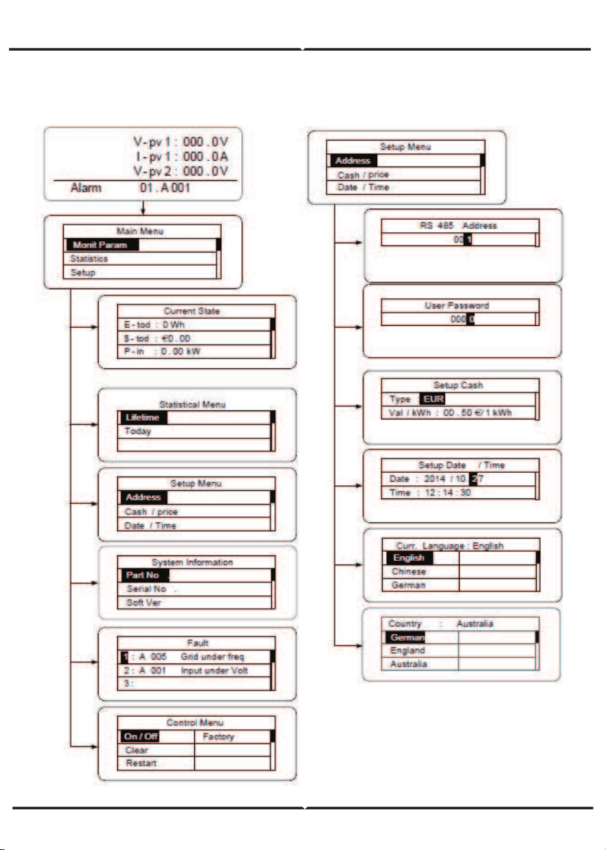
FUNCTIONS OPERATION
Most of the parameters can be viewed and set through the LCD screen and operation
panel.
M ai n Me nu
Monit Param
Statistics
S et up
S ys te m In fo
Fault Info
Current State
E - t od : 0 Wh
$ - t od : €0 . 00
P - in
: 0 . 00kW
Figure 19 Main interface
Figure 20 Monitoring parameters
STATISTICS
Press “ ” and “ ” in the main interface to
select “Statistics”, and then press “ENT” to
view the parameters which is shown in
Figure 22 .
HISTORY
Press “ ” and “ ” in the main interface to
select “History”, and then press “ENT” to
view the parameters which is shown in
Figure 21.
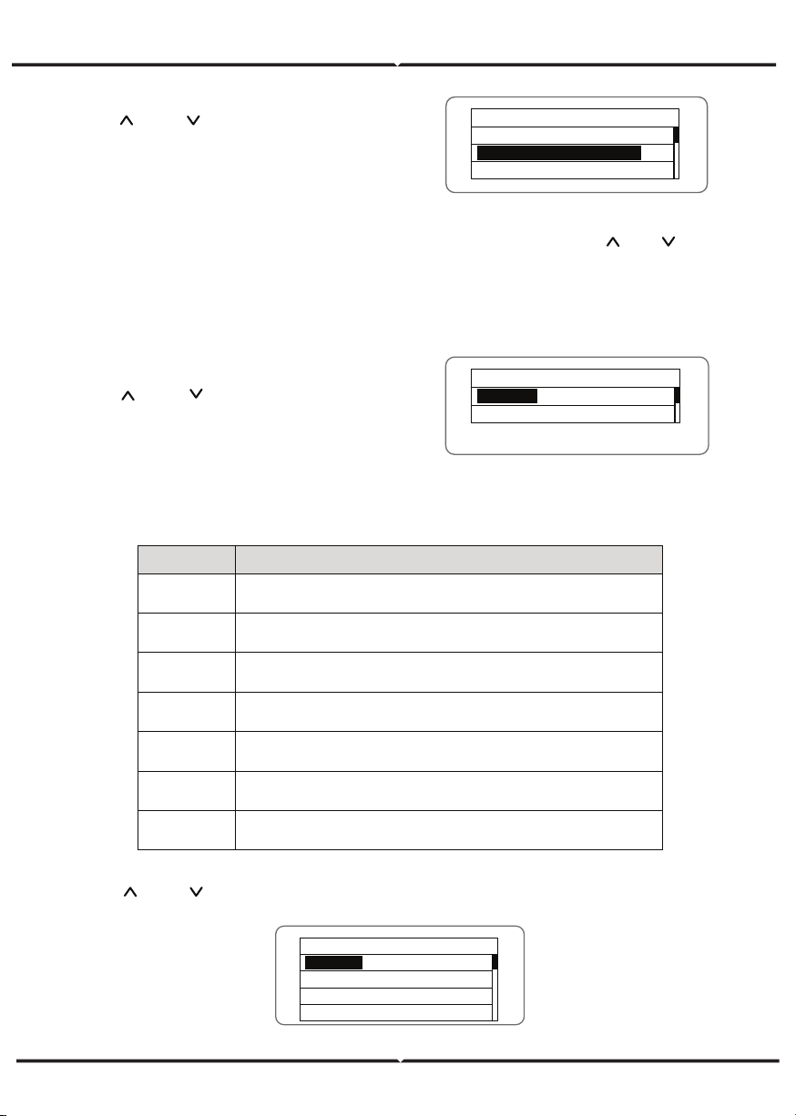
PARAMETER SETTINGS
Press “ ” and “ ” in the main interface to select “Setup Menu”, and then press “ENT” to
view the parameters which is shown in Figure 23.
The information in table below can be viewed in the statistical menu.
Statistical Menu
Lifetime
T od ay
Figure 22 Statistic information
Figure 21 History parameters
Table of statistic information
Content Detailed
Lifetime
Total operation time, total power produced, total power saved, total
CO
2
reduction in lifetime
Time
statistics
Total power produced, total power saved, peak power and total CO
2
reduction in statistical time
Day statistics
Total power produced, total power saved, peak power and total CO
2
reduction in current day
Latest 7 days
Total power produced, total power saved and total CO
2
reduction in
latest 7 days
Latest 1
month
Total power produced, total power saved and total CO
2
reduction in
latest 1 month
Latest 30
days
Total power produced, total power saved and total CO
2
reduction in
latest 30 days
Latest 1 year
Total power produced, total power saved and total CO
2
reduction in
latest 1 year
Setup Menu
A dd re ss
Cash / p ri ce
Date / Time
Language
Figure 23 Setting information
History 0
2012 / 01/ 05 11 : 32: 16
A 0 05 : G ri d un de r fr eq
“Historical record” can display 32 pieces of historical information, press “ ” or “ ”
key to look through the historical information, press “ESC” to return. The number on
the upper right corner of the first row is the number of historical record, the 2nd row
(as shown in Fig 21) displays the date and time when fault occurred or restored, and
the 3rd row displays detailed information of fault code. When the 3rd row displays in
inverse color, it indicates fault occurred, otherwise it is fault restored.
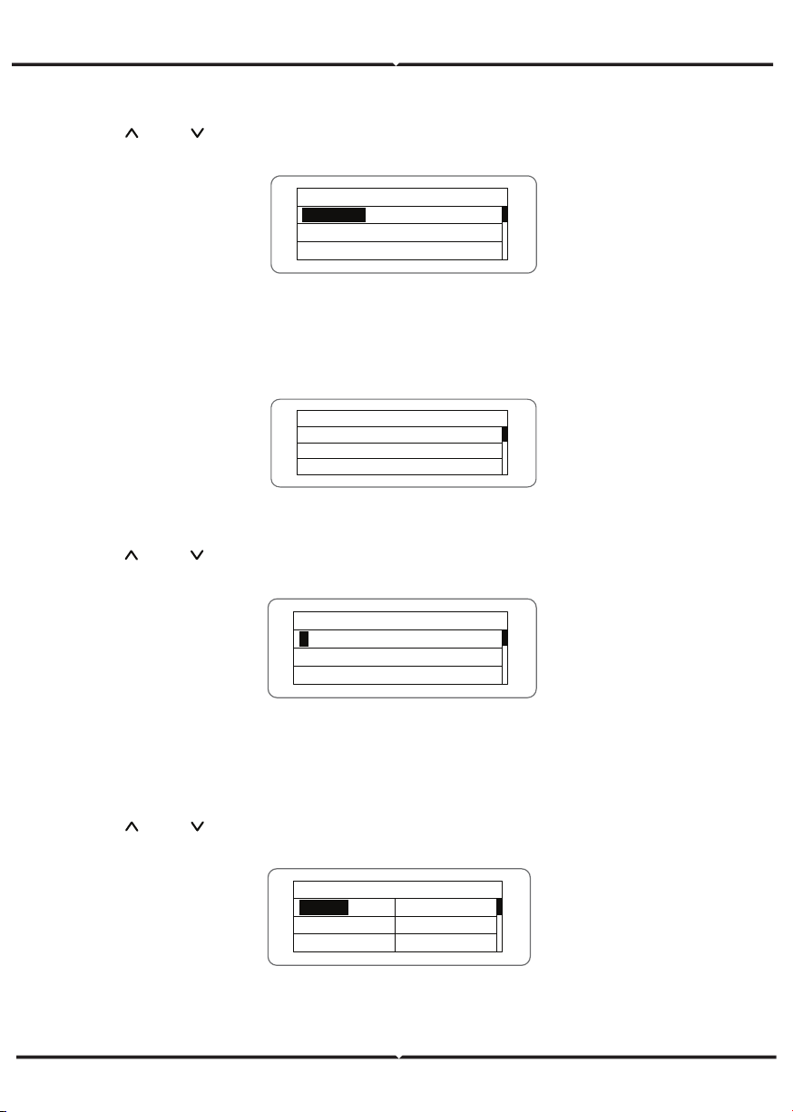
“Setup menu” can realize parameter setup shown in table of parameters setting.
LCD MENUS:
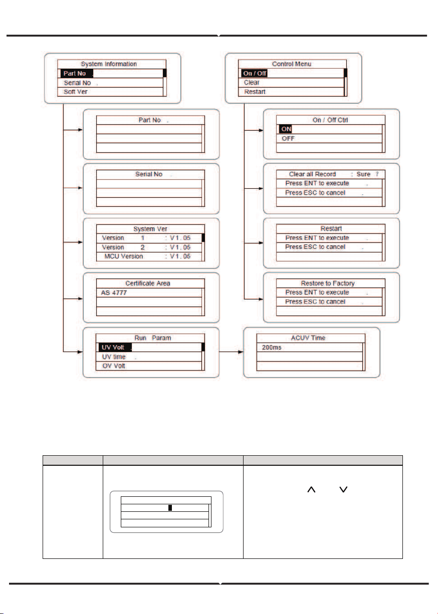
Table 6-3 Parameters setting
Setting item
LCD display
Instruction
RS485
Address
RS485 A dd re ss
0 01
1
Enter into the interface and edit the
data through “
” or “ ”. And then
press “ENT” again to the next bit.
After editing the three bits, press
“ENT” to save the edition and press
“ESC” to exit.
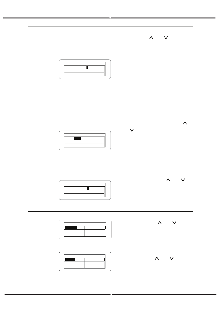
User
password
U se r Pa ss wo rd
0000
0
Enter into the interface and edit the
data through “
” or “ ”. And then
press “ENT” again to the next bit.
After editing the four bits, press
“ENT” to save the edition and press
“ESC” to exit.
The default password is “0000”; the
user can enter into the setting
interface without password. If the
password is not “0000”, the user can
enter into the setting interface with
password.
Setup Cash
Setup Cash
Type : E UR
V al / k Wh : 00. 50€/ 1 k Wh
E UR
Enter into the interface and edit the
currency type and cash through “
”
or “
”. And then press “ENT” again
to the next line. After editing the four
bits, press “ENT” to save the edition
and press “ESC” to exit.
The currency types include EUR,
POD, CNY and USD.
Setup
Date/Time
Setup Date / Time
Date : 2012 / 01/ 15
Time : 12: 14: 30
1
Enter into the interface and edit the
date and time through “
” or “ ”.
And then press “ENT” again to the
next line. After editing the four bits,
press “ENT” to save the edition and
press “ESC” to exit.
,
Language
Curr. Language : English
English
Chinese
German
Dutch
Enter into the interface and edit the
language through “
” or “ ”. And
then press “ENT” again to save the
edition and press “ESC” to exit.
The default language is English.
Select
Country
Country : Australia
Germany
England
Australia
Greece
Denmark
Holland
Enter into the interface and select
country through “
” or “ ”. And
then press “ENT” again to save the
edition and press “ESC” to exit.
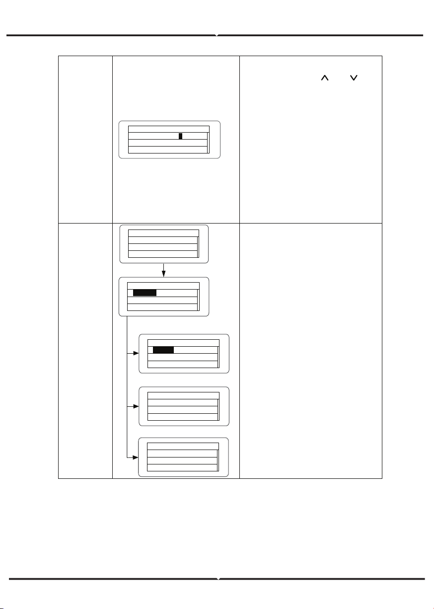
User period
U se r Pe ri od
S ta rt : 2012 - 01- 01
E nd
: 2012 - 02- 01
1
Enter into the interface and edit the
user period through “
” or “ ”.
And then press “ENT” again to the
next bit. After editing, press “ENT” to
save the edition and press “ESC” to
exit.
Of which, the setting time and date
needs to be later than the system
setting, and the start time needs to
be earlier than the end time.
The setting date and time is used for
the statistical information.
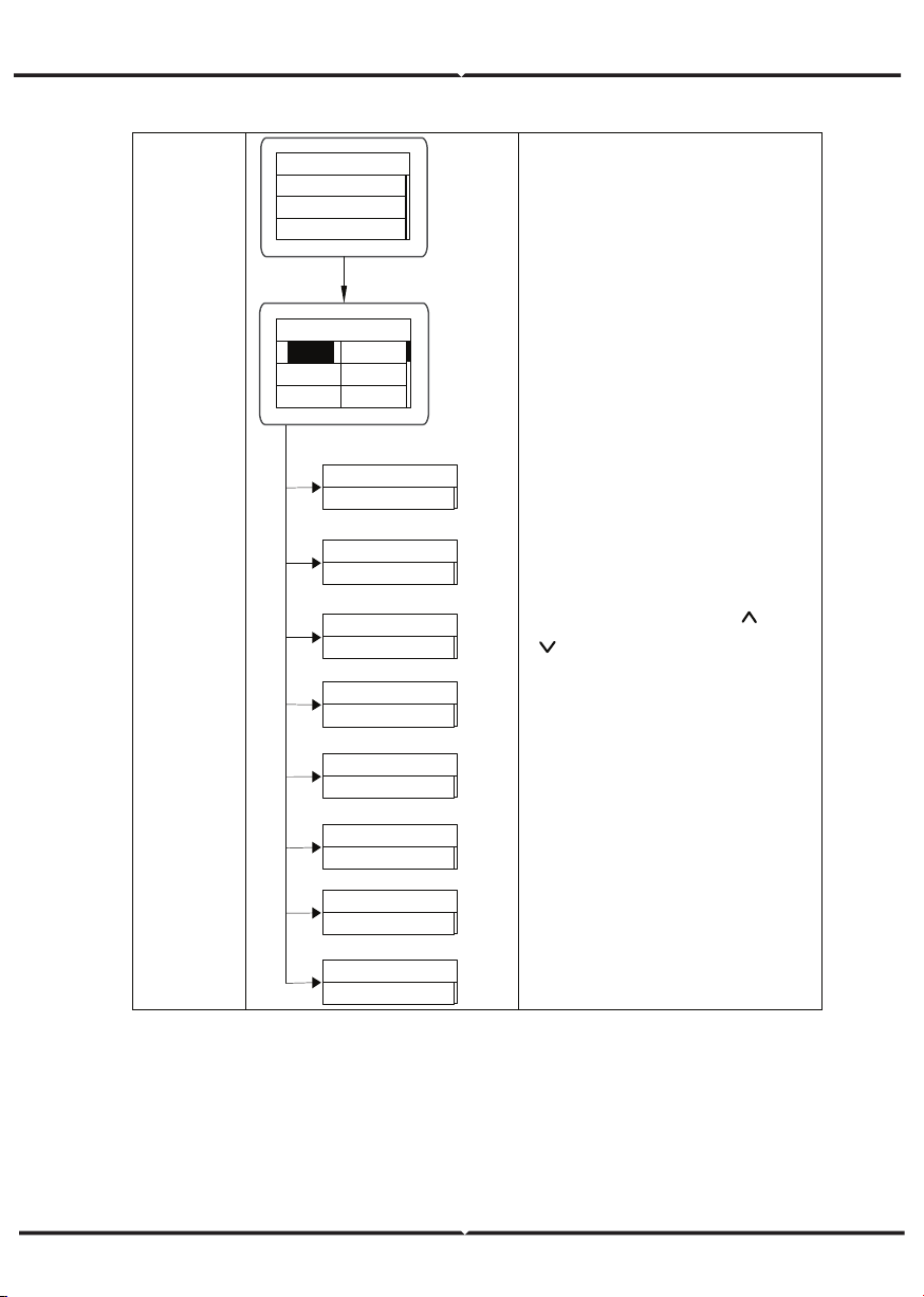
Set power
set power
P-Lmt
Mode
LmtPower
P.Factor
Limit Mode: Invalid
Invalid
Auto
Manual
Limit Power
100%
Power Factor
Grid Tied Mode
Normal Mode
Power Factor:1.00
Input password
0000
The password is needed when enter
into the interface of “Set power”. Get
the password from the supplier if
necessary. There are 3 submenus:
①P-Lmt Mode: invalid (limited power
function is invalid),auto (special for
single phase) ,manual (set the limit
of output value manually); ②
LmtPower: this function is only valid
when the P-Lmt Mode is manual, the
percentage is that of the rated power
and the setting range is from 10% to
100%; ③Power factor: includes
normal model (default value “1”),
current advanced mode and current
hysteresis mode and the setting rage
is -0.9-0.99.
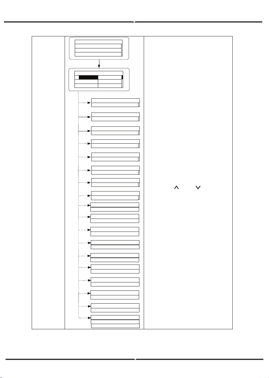
Run Param
Run Param
UV Volt
UV time
OV Volt
OV time
UF Freq
UF time
ACUV Volt(phase volt)
184V
ACUV Time
0.20s
ACOV Volt(phase volt)
263V
ACOV Time
0.20s
ACUF Freqency
47.6Hz
ACUF Time
0.20s
ACOF Freqency
51.4Hz
ACOF Time
0.20s
Input password
0000
Password is required when enter into
the interface of “Run Param”. Get the
password from the supplier if
necessary. Set ACUV Volt, ACUV time
and others under the related
submenus, and then press “
” and
“
” to modify, and finally press
“ENT” to confirm.
Run Param
Run Param
UV volt 1
UV time 1
OV volt 1
OV time 1
UF Freq 1
UF time 1
ACUV Volt(phase volt)
115V
ACUV Time
00.04s
309V
00.02s
ACUF Frequency
47.99Hz
00.12s
50.50hz
00.12s
·
Input Password
0000
196V
252V
0.19s
01.90s
49.49Hz
595s
50.2Hz
115s
Run Restart Time
060s
Island protect:on
OFF
ON
ACOV Volt(phase volt)
ACOV Time
ACUF Time
ACOF Frequency
ACOF Time
ACUV Volt(phase volt)
ACUV Time
ACOV Volt(phase volt)
ACOV Time
ACUF Frequency
ACUF Time
ACOF Frequency
ACOF Time
There are 2 protections under
G83/G59(UK) and PEA(Thailand)
standards, and there is only one
protection under other grid tied
standard.
Set ACUV Volt, ACUV time and others
under the related submenus, and
then press “
” and “ ” to modify,
and finally press “ENT” to confirm.
Generally, it is only necessary to set
ACUV2, ACOV2 and ACUF2 value for
ACUV, ACOV and ACUF protection.
And it is necessary to set ACOF1 and
ACOF2 together for ACOF protection.
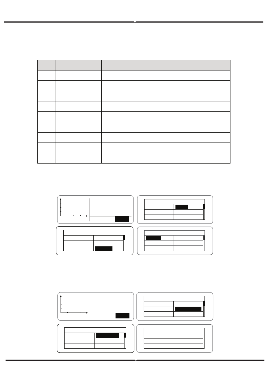
SYSTEM INFORMATION
Press “ ” and “ ” in the main interface to select “System Information”, and then press
“ENT” to view the parameters which is shown in Figure 24.
The system information include “product model”, “serial No.”, “software version” and
“certificate version”. If select "Software Version" in the "System Version", can view the
inverter Version 1, Version2, MCU Software Version, RS485 protocol and other informa-
tion, as shown in Figure 25.
FAULTS
Press “ ” and “ ” in the main interface to review the fault history, and then press “ENT”
to view the sub-menu which is shown in Figure 26.
There are 8 pieces of fault information in the record which is shown in Figure 26. Otherwise
it will display “No Fault!” Refer to HISTORY for more detailed information.
INVERTER CONTROL
Press “ ” and “ ” in the control interface, and then press “ENT” to view the sub-menu
which is shown in Figure 27.
System Information
Part No .
Serial No .
Soft Ver
Figure 24 System information
S ys te m Ve r
V er si on 1 : V 1 . 05
V er si on 2 : V 1 . 05
MCU Version
: V 1 . 05
F au lt
1 : A 005 G ri d un de r fr eq
2 : A 001 Input under Volt
3 :
1
Control Menu
On/ Off
C le ar
R es ta rt
F ac to ry
Figure 27 Control interface
Figure 26 Fault information
Figure 25 System version
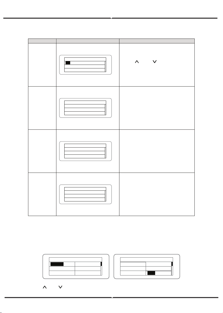
Refer to the table below for detailed information.
GRID CERTIFICATION CHOICE
Power on the inverter by DC input for the first time or after restore factory settings,
the LCD screen will appear a list of countries, requiring the user to choose what
country of use. As shown below:
Press the “ ” or “ ” button to select the country (refer to the below table), press
the ENT button to complete the setting.
Table of inverter control
Control item
LCD display
Instruction
On/Off
control
On/ Off Ctrl
ON
O FF
Control the “On/Off” through the
panel.
Press “
” and “ ” in the control
interface to select the operation. Press
“ENT” to ensure the operation and
press “ESC” to return.
Restart
R es ta rt
Press ENT to execute .
Press ESC to cancel .
Restart the inverter through the
panel. And save the all settings and
operation record.
Press “ENT” to ensure restarting and
the inverter will begin to self -inspect
or press “ESC” to return.
Record clear
Clear all Record : Sure ?
Press ENT to execute .
Press ESC to cancel .
Press “ENT” to ensure clear all records
or press “ESC” to return.
“Record clear” is to clear all setting
parameters through the panel, restore
to the factory setting and save all
history operation records.
Restore to
factory
Restore to Factory
Press ENT to execute .
Press ESC to cancel .
“Restore to factory” is to clear all
setting parameters and history
operation records through the panel,
restore to the factory setting. Press
“ENT” to ensure clear or press “ESC”
to return.
Co un tr y : U ns et
Germany
UK
A us tr al ia
Greece
D en ma rk
H ol la nd
C ou nt ry : U ns et
Other
D en ma rk
H ol la nd
C hi na
T ha il an d
Greece
After finish the country setting, please follow the user manual required with the proper use
of inverter.
No. Country Certification Remark
1
Germany
VDE0126& AR-N4105
2 UK G83/G59
3 Australia AS4777
4 Greece VDE0126
5 Denmark TF3.2.1
6 Holland C10/C11
7 China CQC
8 Thailand PEA
9 Other VDE0126
Comparison Table: Available countries and their grid certification
The user can change the country setting through the following ways:
LCD screen:MENU→Main Menu: Setup→Setup Menu: Country→Country:
The user can query the grid certification which has been set through the following ways:
LCD Screen:MENU→Main Menu: System Info→System Information: Cert. Area→
Certificate Area
V - pv1 : 0 00 . 0 V
I
- pv1 : 0 00 . 0 A
V - pv2 : 0 00 . 0 V
01. A 001
MENU
A la rm
p
h
MENU
M ai n Me nu
Monit Param
H is to ry
Statistics
S et up
S ys te m In fo
Fault Info
Setup Menu
A dd re ss
K ey pa d PW D
Cash / p ri ce
Date / Time
Language
C ou nt ry
Co un tr y : C hi na
Germany
UK
A us tr al ia
Greece
D en ma rk
H ol la nd
V - pv1 : 0 00 . 0 V
I
- pv1 : 0 00 . 0 A
V - pv2 : 0 00 . 0 V
01. A 001
MENU
A la rm
p
h
MENU
M ai n Me nu
Monit Param
H is to ry
Statistics
S et up
S ys te m In fo
Fault Info
S ys te m In fo rm at io n
P ar t No .
S er ia l No .
S of t Ve r
Cert . Area
R un P ar am
Certificate Area
AS4777
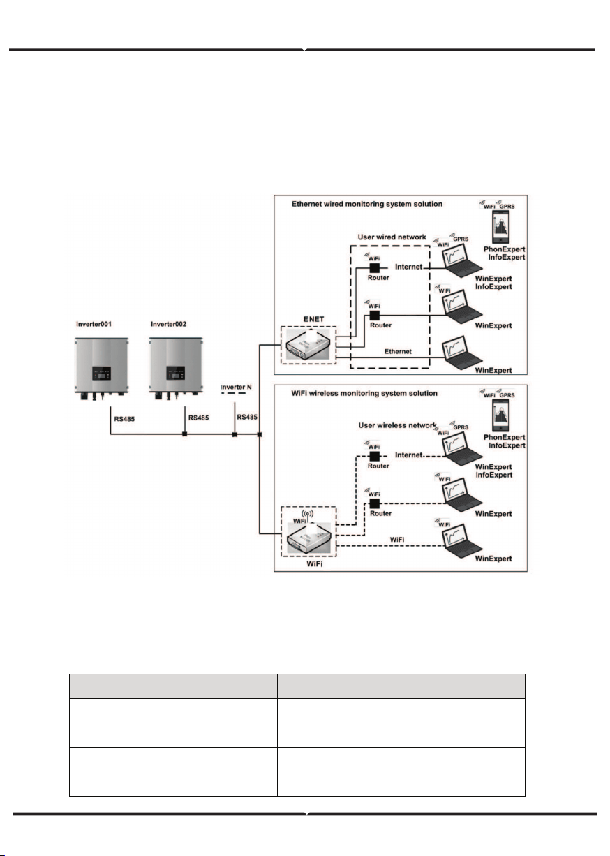
MONITORING COMMUNICATION
This chapter describes the communication connection of inverter and monitoring system
(Industrial master, private computers, smart phones and so on).
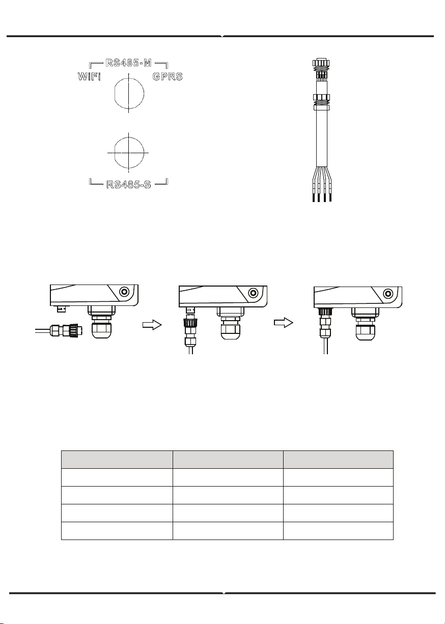
The standard communication mode of grid-tied solar inverter is RS485 which includes
“RS485-M” and “RS485-S” ports. The RS485-M ports can communicate with private
computers, smart phones and so on. The system monitoring solution is shown as Figure
below.
Figure 28 Monitoring system of inverter
STANDARD COMMUNICATION
Table of pins on inverter instruction
Pin on inverter Definition
1(Red) +5VDC
2(Orange) A (RS485+)
3(Brown) B (RS485-)
4(Black) GND
1
+5V
485+
485-
GND
23
4
Optional accessories Inverter port Port of upper PC
Ethernet convert RS485-M RJ45 pin
WiFi converter RS485-M WiFi signal
GPRS converter RS485-M GPRS signal
ENET converter RS485-M Ethernet port
(2) According to the table of Optional communication accessories, connect the commu-
nication connector pinout and the user's device, make sure the connection is correct.
(3) Please download the monitoring software “ WinExpert” and its operation instruction
from our website.
Please download the connection instruction, operation manual and commissioning
tools on website.
Note: the optional accessories are not standard-configured, need to buy separately.
Table of Optional communication accessories
(1) Connect the communication connector configured for the inverter to the RS485
terminal of the inverter, as shown in Fig b;
CONNECTION STEPS:
Figure 29 RS485 pin on inverter
Figure 30 Communication connector
Figure 31 Detailed connectiona
TROUBLESHOOTING
Table of Fault code
Fault code Message Instruction Fault analysis
A
A001 Input UV Input undervoltage
PV1 undervoltage
PV2 undervoltage
A002 Bus UV Bus undervoltage DC input
A003 Grid UV AC undervoltage Low voltage of the public grid
A004 Grid OV AC overvoltage High voltage of the public grid
A005 Grid UF AC underfrequency Low frequency of the public grid
A006 Grid OF AC overfrequency High frequency of the public grid
A007 Clock Fail Clock alarm Wrong setting
A009 Cmd Shut Manual stutdown
Stop by the operation panel or
upper PC
A011 Grid Loss
The public grid
disconnects.
Check if inverter AC connection is
well
E
E001 Input OV Input overvoltage DC input overvoltage
E003 Bus OV Bus overvoltage Internal bus voltage
E004 Boost Fail Voltage-boost fault Voltage-boost fault of the inverter
E005 Grid OC AC overcurrent Internal AC overcurrent
E006 OTP Over temperature Internal over temperature
E007 Riso Low
Low isolation
impedance
Low isolation impedance of the
external port system
E008 IGBT drv
IGBT drive
protection
IGBT drive protection of the
inverter
E009 Int Comm
Internal
communication
fault
Master-slave DSP communication
disabled
Error of master-slave DSP check
bit
E010 ILeek Fail
Huge leakage
current
Huge leakage current of the
system or inverter
E011 Relay Fault Relay fault Internal relay fault
E012 Fan Fail Fan fault Internal fan fault
E013 Eeprom Memory error Internal memory error
E014 Dc inject High DC injection
High DC injection during AC
output
E015 OutputShort
Output short-
circuit
Output short-circuit
E018 Input OC Input overcurrent DC input overcurrent
E019 Incnst
Data consistency
fault
Inconsistent grid voltage,
frequency, leakage current or
AC/DC injection
E020 PowerReversed DC power reversed DC power reversed
E021
Meter
commErr
Power meter
communication is
faulty
The communication between
smart meter and inverter is faulty
(when anti-feedback function is
enable)
E022 FreqChg
Frequency is
changed
Fluctuation of grid voltage is over
inverter normal sustainable range
E023 PE Loss
PE wire not
connected
The PE wire is unconnected (this
error code only available under
AS4777 safety)
E024 MeterLoss
The smart meter
not connected
The smart meter not connected
E025 Locking
The inverter is
locked
The inverter is locked
E026 Run Limit Light load
Light load (when anti-feedback
function is enable)
E028 DRM0 Loss
The DEM0 box not
connected
The DRM0 box is unconnected
(this error code only available
under AS4777 safety)
TECHNICAL PARAMETERS
Table of technical parameters
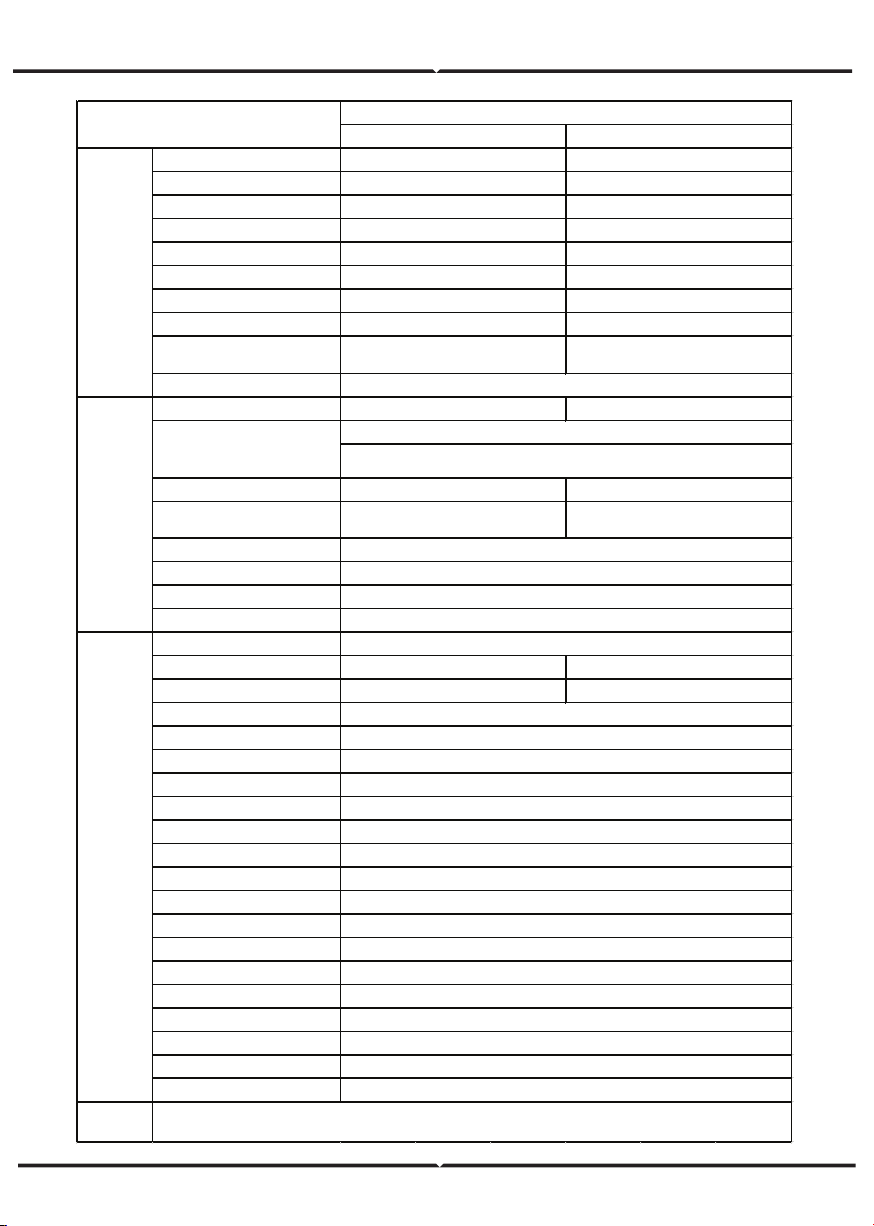
3kW-2M
5kW-2M
M ax. DC vo ltage (V)
600
600
Starting vo ltage (V)
12 0
12 0
M PP T vo ltage(V) 125-550 125-550
Operation vo ltage (V) 180-500 250-500
M PP T/strings per M P P T
2/1
2/1
M ax. DC po wer (W)
3000
5000
M ax. input current (A ) 8×2
12 × 2
Isc PV 9×2
14 × 2
M ax inverter backfeed current to the
array
0
0
DC switch
M ax output po wer
3000
4600
M ax. AC current (A)
14
20
M aximum o utput overcurrent
protection
27
40.2
M aximum o utput fault current
AC inrush current
Po wer facto r
Harmo nic distortio n
Coo ling
M aximum efficiency 97.60% 97.40%
European efficiency 96.50%
96.50%
M PP T efficiency
Pro tection degree
Po wer co nsumption
Iso latio n mode
Pro tective class
Overvo ltage category
inverter to po lo gy
Po llutio n degree
Operation temperature
Relative humidity
M ax. altitude(m)
Displaying
Systerm language
Communication
DC terminal
Noise dB (A )
Installatio n mode
Pro tection
M odel
Single-phase
Input(DC)
Optional
Output(A C)
Voltage(V)/ frequency(Hz)
180~270Vac、 50Hz(47~51.5Hz) / 60Hz(57~61.5Hz)
VDE0126& A R-N4105、 AS4777.2/A S4777.3、CQC、 G83-2、G59-
3、 C 10 / 11、 TF 3.2.1、P EA
104A,37.2ms
Less than 2 A
-0.9~+0.9 (adjustable)
< 3% (rated power)
System
Natural co o ling
99.90%
IP 65
< 1W
Transfo rmerless
I
A C:III,P V:II
Non-iso lated
3
(-25
℃
~ +6 0
℃
) ,derate after 45
℃
4~100%, Co ndensatio n
<2000 (derate if the altitude> 2000)
LED/ LCD, backlit display
English, Chinese, German, Dutch
RS485 (standard); handheld keypad; WiFi (o ptio nal)
BC03A / B C03B
≤25
Wall installatio n
Input o vervo ltage protection, input overcurrent protection, DC iso lation monito ring, DC monito ring, grounding fault current
monito ring, grid mo nitoring, island pro tection, sho rt circuit protection, overheating protectio n