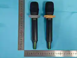
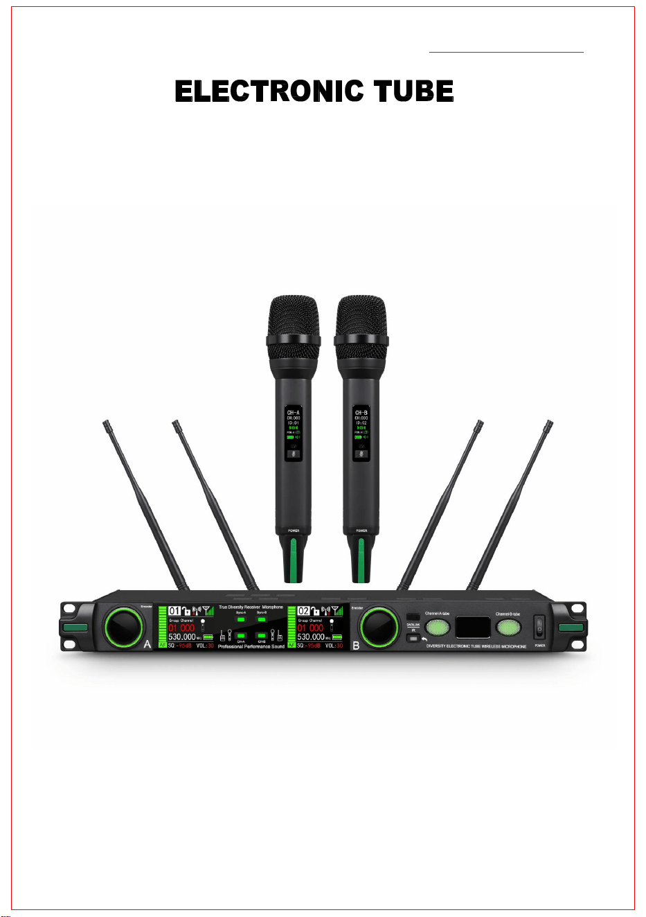
Wireless Microphone User Guide
Professional UHF Diversity Wireless Microphone
.
UHF530-580MHz
Total System Bandwidth: 50 MHz, Dual‑2000‑Channel Design The
audio signal adopts a vacuum‑tube amplifier circuit design.
Maximum Deviation: ±45 kHz
The system adopts dual‑tuning true‑diversity for signal reception
S/N
Ratio:
>90
dB
Total
Harmonic
Distortion
(T.H.D.):
<0.2%
@
1
kHz
Audio Frequency Response: 30Hz‑16kHz @ ±3dB
Read carefully before use
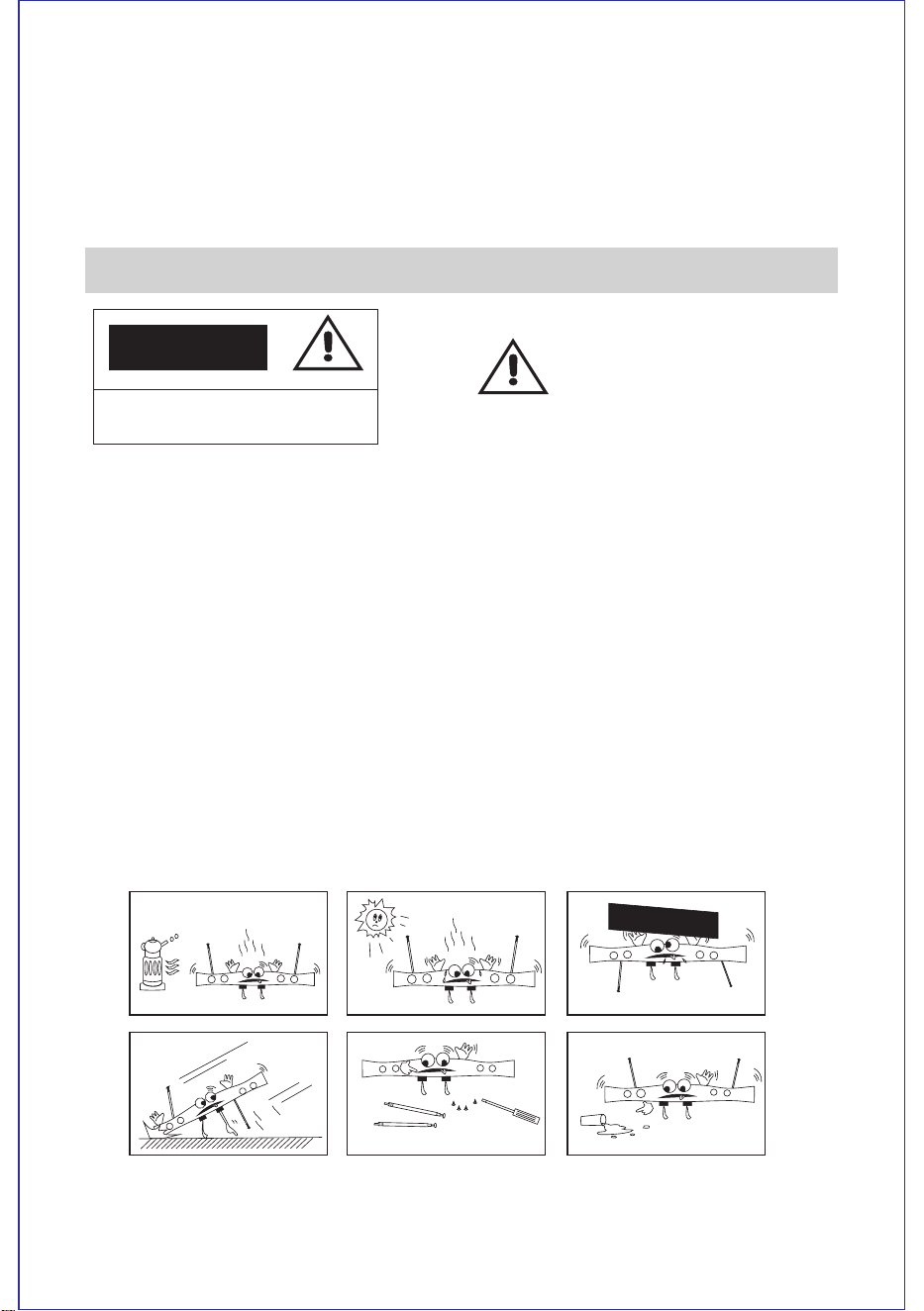
Do not operate our baby of the situations as above!
1. read the user guide-read carefully about safety and manipulation requests.
2. keep the manipulation introductions - please keep this manual for further need of safety and manipulation
requests.
3. beware of the warnings - please notice the warnings for the machine while operating.
4. follow the denotements -please follow the denotements while operating.
5. accessional devices- only accessional devices from original produers of the machine are required.
6. humidity cautions- keep the machine away from humid condictions.
7. aeration- please keep the machine in well ventilated conditions at all time, there should be at least 5cm
clearance around the device.
8. heat source-please keep the devices away from heat sources,including, radiator, heater, stove, etc.
9. power supply-please utilize the labelled voltage on the device.
10. no exposed fire should be on the device e.g. flaming candles.
11. please do not litter the batteries, dispose them into the appointed place when they are fully used.
12. no liquid or weights should be on the device, no water dripping or splashing onto lin to the device.
13. the device is also suitable in torvied zone,and variable zone.
14. This equipment uses a power plug as a disconnect device, which should be kept easy to operate.
15. This product is a Class 1 device and should be connected to a power output socket with protective
grounding.
Only professionals can disassemble and assemble the system!
Please do not open up the system. technicians
are always the only persons to sort out any
Thank you for purchasing our wireless microphone system.
With years experience to producing wireless microphone system,our crews are confident to say we are the
expert of manufacturing wireless microphone system. Our products are suitable for KTV room, karaoke stage
and also school,showplace,stadium.and so on. Our products are convenient to operate,and of stably great
quality.
So they are widely favoured by out customers We promise highly of first class quality, and also first class
service. Our professional technician crew is always ready to help you with any technical questions!
technical operations.
STRICTLY READERS ARE TOLD
1
Warning: Beware of electric shock fine; machine must be kept away humid conditions!
CONTIONS

1:Built‑in 2000 frequencies. Frequencies can be modified for multi ‑unit operation according t
System Highlights
o
different requirements.
2:Built‑in 9 groups, each group is preset with 10 interference‑free frequencies for convenient
multi‑unit stacking operation.
3:The system has a built‑in spectrum analyzer function, which allows direct observation of
interference signals. Manually adjust the frequency to avoid interference signals.
4:The system is equipped with a built‑in 6‑step signal attenuator, which allo
ws adjusting the
operating range as required.
5:The receiver frequency can be switched for handheld or bodypack operation.
6:The system features built‑in 9‑band equalizer adjustment for treble and bass.
7:This system adopts digital ID code locking. Each channel is assigned a unique ID code to
prevent cross‑channel interference and deliver high anti‑interference performance.
8:The audio is processed wi
th innovative vacuum‑tube technology, delivering full‑bodied,
springy and powerful low frequencies, prominent mid‑frequencies, as well as delicate and
clear high frequencies.
11:The transmitter is equipped with one‑touch mute, selectable high/low power, smart mute and
other functions.
9:This system features true‑diversity reception with four antennas and dual high‑frequency
tuners to extend operatin
g range, suitable for all types of performances.
System Electrical Parameters
System Parameters
Frequency Range:530-580MHz
Frequency Tuning Step:25KHz/1MHz
Reception
Receiving Antenna: BNC rubber antenn
Frequency Channels:2000CH
Frequency Bandwidth:50MHz
Reception Mode: Dual‑tuner True‑Diversity
a
Total Power Consumption: 14W (2CH)
Operating Range: >150 m
(under ideal operating conditions)
Frequency Stability:±0.002%
Receiver Sensitivity:-102dBm
Image Rejection: >80 dB
SNR: >90 dB
Expansion Ratio: 1:2
Dynamic Range: >100 dB
10:The receiver is powered by ±12V du
al power supply to improve audio dynamic range and
reduce total harmonic distortion.
Power Supply:AC100-240V
Audio Output: 0‑300 mV @ 1 kHz, Modulation:
30 kHz Input
Audio Amplification: Tube Amplification
Processing
Receiver Parameters
Transmitter Parameters
Frequency Stability: ±0.002%
Transmit Power: 10 mW / 30 mW
Current Consumption: < 120 mA @ Input
Voltage 3 V
Second‑Harmonic Rejection: >50 dBm
Max
imum Deviation: ±45 kHz
Compression Ratio: 2 : 1
Pick‑up: Cardioid dynamic microphone capsule
Transmitting Antenna: Built‑in loop copper
wire antenna
Battery Used: Two AA 1.5 V / 1.2 V batteries
Audio Output: 2 independent XLR balanced
outputs, 1* 6.35 mm mixed output.
2
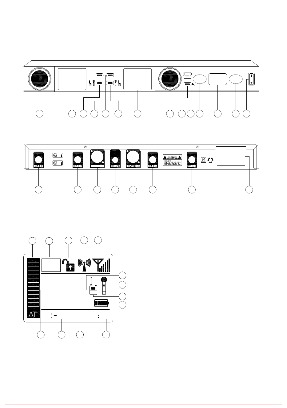
Wireless Receiver Function Description
Professional Performance Sound
CH-A
CH-B
Sync-A
Sync-B
True Diversity Receiver Microphone
A
B
ELECTRONIC TUBE WIRELESS MICROPHONE
Channel-B-tubeChannel-A-tube
POWER
DATALINK
iR
21
3
1:GND
2:HOT
3:COLD
21
3
1:GND
2:HOT
3:COLD
BALANCED-A
BALANCED-B
AC 100-2
40V/50-60Hz
BALANCED-B
CAUTION !!
1
30
SQ
95
dB
02
530.
MHz
000
000
02
A
B
1:A/B Encoded potentiometer / Long press to lock or unlock /
Rotate directly to adjust volume. The knob halo ring
breathes‑flashes when no transmitting signal is received, and
stays steadily lit when transmitting signal is received.
2:A/B 2.4-inch TFT Display screen
3:A Channel Handheld/Lavalier Toggle Key
4:A Channel IR Pairing Key
7:IR Pairing Window
8:Function Exit Key
9:A/B Channel Tube Display W
indow
10:Brand Display
11:Power Switch
12:Receiving Antenna
13:A/B Channel Balanced Output Port
14:A+B Channel Mixed Output Port
15:AC100-240V Power Input Socket
16:AF Level Display
17:ID Code Display
18:Lock/Unlock Display
19:Diversity Switch Display
20:RF Signal Level Display
28:Group Channel Display
22:Handheld Usage Display
23:Lavalier Usage Display
24:Transmitter Battery Level Display
25:Volume Display
26:Fre
quency Display
27:Received Signal Strength Display
21:Receiver Frequency‑Channel Count Display
WARNING: The power voltage of this device poses potential hazards. Do not disassemble the chassis or alter the
factory‑set operating voltage without authorization; otherwise, the safety certification will become
invalid.All repairs must be performed by qualified service personnel.
2 3
4 5
6 2 1
7
98
10
9 11
12
12 13 14 13 12 12 15
16
17
18
19
20
21
22
23
24
25
26
27
28
5:B Channel IR Pairing Key
6:B Channel Handheld/Lavalier Toggle Key
Group
Channel
VOL
3
Channel:
Freq:530.000MHz
Channel:000
Freq:530. MHz
Channel:000
Freq: .000 MHz
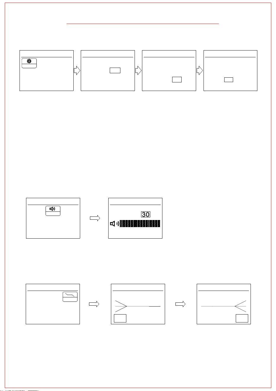
1:Setting Interface
2:Channel Number Adjust
3:Frequency 25KHz Step
Adjustment
4:Frequency 1MHz Step
Adjustment
Operation:
1.Short‑press the encoder knob to enter the function setting interface. Rotate the encoder knob to select the menu.
2.Short‑press the encoder knob again to access the channel‑count setting. Rotate the encoder knob for
adjustment. The channel number range
s from <000‑009>, with 10 available channels in total.
(Note: When the preset frequency group is set to <02‑10>, you can directly adjust the channel number
of group <02‑10>, without entering the frequency‑group menu to modify the channel number for group
<02‑10>).
3.Short‑press the encoder knob again to enter the frequency setting. Rotate the encoder knob for
adjustment with 25KHz frequency step.
(
Note: When the preset frequency group is selected as <01>, you can adjust the frequency directly,
without entering the frequency‑group menu to modify the frequency for group <01>.)
4.Short‑press the encoder knob again to enter the frequency setting. Rotate the encoder knob for
adjustment with 1MHz frequency step.
(Note: When the preset frequency group is selected as <01>, you can adjust the frequen
cy directly,
without entering the frequency‑group menu to modify the frequency for group <01>.)
VOL:
2:Volume Adjustmen
2)Volume Setting
t
1.Short‑press the encoder knob to enter the function setting interface. Rotate the encoder knob to select the menu.
2.Short‑press the encoder knob again to enter the volume setting. Rotate the encoder knob for adjustment. The
volume has 30 adjustable levels.
LOW
HIG
3)EQ Setup
LOW
HIG
2:Bass Adjustment 3:Treble Adjustment
1.Short‑press the encoder knob to enter the function setting interface. Rotate the encoder knob to select the <EQ> menu.
2.Short‑press the encoder knob again to enter the bass setting. Rotate the encoder knob for adjustment. A total of 3
levels are available.
3.Short‑press the encoder knob again to enter the treble setting. Rotate the encoder knob for adjustment.
A total of 3
levels are available.
Frequency
Volume
Frequency Frequency Frequency
EQ
FREQ
VOLUME
EQ
Volume
1:Setting Interface
Operation:
EQ EQ
1:Setting Interface
Operation:
000
000
530
Wireless Receiver Function Description
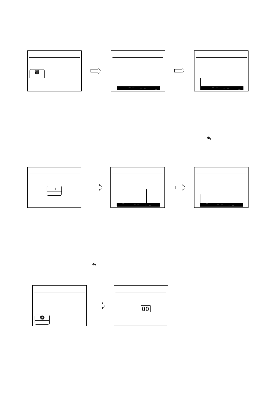
1)Frequency Setting
4
自动扫频
2:Auto‑Search
1.Short‑press the encoder knob to enter the function setting interface. Rotate the encoder knob to select the
<Auto‑Scan> menu.
2.Short‑press the encoder knob again to enter auto‑search mode. The system will automatically scan the
full frequency band for clear channels. After scanning, the clean frequency will be displayed at the
upper‑right corner. The whole process takes approximately 10‑15 seconds.
530.000
3:IR Frequency Sync
530.000
SYNC----
3.Press the <Sync> key to send an IR signal to synchronize frequency with the transmitter. This
function enables the system to automatically lock onto a clean frequency. Press the < > key to
exit this function.
自动扫频 自动扫频
SCAN
1:Setting Interface
Operation:
5)Spectrum Scan
Spectrum
530.000
(2)
(2)
(1)
1.Short‑press the encoder knob to enter the function setting interface. Rotate the encoder knob to select the
<Spectrum> menu.
2.Short‑press the encoder knob again to enter the spectrum analyzer interface. The coordinate signal bar
(1) will be displayed on the screen. If other interfering signals exist, their spectrums will also be shown (2).
When selecting a frequency, rotate the encoder knob; the coordinate signal bar will move accordingly, and
the frequency value shown at the upper‑right corner will change simultaneously. Do not select or position
the coordinate signal bar close to any interfering‑signal areas. After selection, press the <Sync> button on
the panel to synchronize frequency with the transmitter. This function is for manually selecting a clean
frequency. Press the < > button to exit this function.
2:Spectrum Scan
3:IR Frequency Sync
530.000
SYNC----
6)ID Setting
Serial Number
ID:
1.Short‑press the encoder knob to enter the function setting interface. Rotate the encoder knob to select the menu.
2.Short‑press the encoder knob again to enter the ID setting. There are 100 available IDs ranging from <00‑99>.
This ID shall match that of the transmitter. Users can quickly locate the corresponding receiver by checking the
ID displayed on the transmitter.
2:ID Setting
SPECT
ID
Spectrum Spectrum
1:Setting Interface
Operation:
1:Setting Interface
Serial Number
Operation:
Wireless Receiver Function Description
4)Auto‑Scan Setting
5
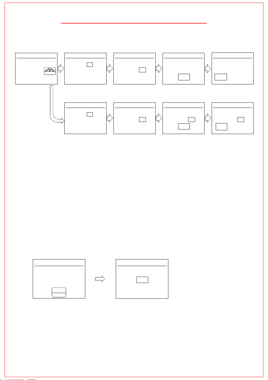
1.Short‑press the encoder knob to enter the function setting interface, then rotate the encoder knob to
select the menu.
2.Short‑press the encoder knob again to access group selection; 10 groups are available in total. When
Group 01 is selected, short‑press again to enter channel selection. Channels range from <000‑999>, with
1000 channels available. Short‑press the encoder knob once more to enter
frequency adjustment with a 25
kHz step. Short‑press the knob again to switch to frequency adjustment with a 1 MHz step.
3.Short‑press the encoder knob to access groups <02‑10>, which are preset groups. Each group stores
10 interference‑free frequencies, and the operation is identical to that of Group <01>.
Group <01> contains all available frequencies of this system. Groups <02‑10> are pre‑configu
red
interference‑free frequency groups. When multiple units are stacked, you can quickly select interference‑free
frequencies from Groups <02‑10>.Frequencies in Groups <02‑10> are pre‑arranged by the system, and
users may also re‑edit them manually following the procedures above.
Example: Channel <000> under preset Group <02> is 640.000 MHz. You can change it to 640.025 MHz or
any other interference‑fr
ee frequency. This operation applies to all Groups <02‑10>.
8)Language Setting
中/英
中文
Language
1.Short‑press the encoder knob to enter the function setting interface, then rotate the encoder knob to select
the menu.
2.Short‑press the encoder knob again to enter the language selection menu, rotate the encoder knob to select
Chinese or English.
2:Language Select
Tip:
CN/EN
Group
Channel:000
Group:
530.000 MHz
530.000 MHz
2:Group 01 Setting
3:Group 02‑10 Setup
530.000 MHz MHz
530.000 MHz
.000 MHz
MHz
.000 MHz
Channel Count Adjust
Frequency 25 kHz Step
Adjust
Frequency 1 MHz Step
Adjust
GROUP
0
530.
530
000
1
1:Setting Interfac
530. 530
000
e
Group Group Group
Group
Group Group Group Group
Channel:000
Group:
01
Channel:000
Group:
01
Channel:000
Group:
01
Channel:000
Group:
02
Channel:000
Group:
02
Channel:000
Group:
01
Channel:000
Group:
01
Channel Count Adjust
Frequency 25 kHz Step
Adjust
Frequency 1 MHz Step
Adjust
Operation:
Language
1:Setting Interface
ENG
Operation:
Wireless Receiver Function Description
7)Preset Frequency Group Setting
6
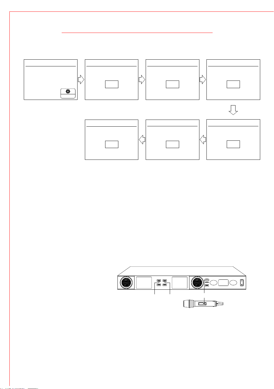
SQ Setup
SQ: dB
Gear 1
1.Short‑press the encoder knob to enter the function setting interface, rotate the encoder knob to select
the menu.
2.Short‑press the encoder knob again to enter the gear selection interface. Rotate the encoder knob
to select gear 1‑6. Gear 1 provides the maximum operating range, while Gear 6 provides the
minimum operating range. Select the appropriate gear according to your actual operating‑range
requirements. (−95dB for maximum range, −70dB for minimum range)
SQ: dB SQ: dB
SQ: dB
SQ: dB
SQ: dB
10)Infrared Frequency Sync Setting
Sync-A Sync-B
A B
DATALINK
iR
1.Aim the infrared window of the
transmitter at the infrared
window of the receiver first.
2.Short‑press the <Sync> button
on the receiver to transmit the
infrared signal. The receiver
infrared window flashes red while
the infrared signal is being
transmitted.
Press the <Sync‑A> button for
frequency sync on CHA channel, and
press the <Sync‑B> button for CHB
channel.
Infrared Window
Sync-A
Sync-B
SQ
1:Setting Interface
Gear 2 Gear 3
Gear6
Gear5
Gear 4
-95 -90 -85
-80
-75
-70
SQ Setup SQ Setup SQ Setup
SQ SetupSQ Setup
SQ Setup
Operation:
Operation:
Tip:
Wireless Receiver Function Description
7
9)SQ Setting
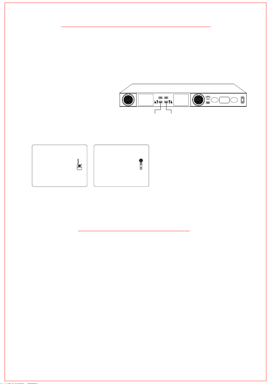
A B
DATALINK
iR
CH-A
CH-B
Operation: Short‑press the CHA/CHB button to
switch between Handheld and
Bodypack modes.
Tip:Operate the CHA channel by pressing the
CHA button; operate the CHB channel by
pressing the CHB button.
CH-A
CH-B
Display on screen when switching
to Bodypack mode
Display on screen when switching
to Handheld mode
System Frequency Response Curve
Wireless Receiver Function Description
8
11)Handheld / Bodypack Switch Setting
Wireless Transmitter Function Description
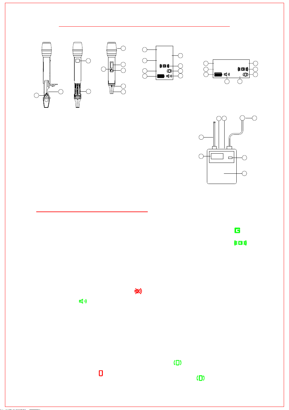
2
3
5
6
4
1
7
8
7
9
Display content in portrait orientation
Content displayed after screen rotation
10
17
11
16
12
15
14
13
18
13
11
16
10
14
12
15
CH:
POW:H
CH-A
ID:
01
000
1:Microphone capsule
2:TFT Display window
3:Mute key
4:Infrared window
5:Power key
6:Transmitting antenna area
7:Battery compartment (When installing
batteries, press the snap buttons on
both sides of the handheld
microphone and pull down.)
8:Brand laser marking position
9:Snap button
10:Channel display
11:ID code display
12:Power display
13:Battery display
14:Mute‑on and mute‑off display
15:Screen rotation
function display
16:Intelligent mute display
17:Frequency channel number display
18:Frequency display
1)Intelligent mute setting
1.When the transmitter is powered on, press and hold the power switch until the symbol <
Transmitter Operating Instructions
>
appears on the screen, which indicates that the intelligent mute function is disabled.
Operation:
2.When the transmitter is powered on, press and hold the power switch until the symbol < >
appears on the screen, which indicates that the intelligent mute function is enabled.
2)Transmitter manual mute setting
Operation: Short‑press the mute button, the transmitter enters mute‑on status. The mute indicator light on
the button lights up, and the symbol < > is shown on the display, the transmitter is muted.
Short‑press the mute button again to turn off mute. The mute indicator light goes out, the
symbol < > appears on the display, and the transmitter works normally.
3)Transmitter power setting
Operation: When the transmitter is powered on, if the power display on the screen shows <POW:L>,
the transmitter is in low‑power mode. Press and hold the mute button for 1 second, the power
display on the screen changes to <POW:H> indicating the transmitter is in high‑power mode.
Press and hold the mute button for another 1 second to return to low‑power mode, and the po
wer
display will show <POW:L>.
Tip: When the transmitter’s intelligent mute function is enabled, it cannot be used on a microphone
stand and must be held by hand. If you need to use it on a microphone stand, please disable the
intelligent mute function.
4)Display screen rotation function setting
Operation: When the transmitter is powered on, if the display shows < >, the display rotation‑view
function is enabled. To disable this function, press the power key three times consecutively.
The display shows< >, indicating the function is disabled. To restore the function, also
>press the power key three times consecutively until the display shows< .
2
3
1
5
6
4
7
530.
MHz
POW:H
CH-A
ID:
000
01
9
10
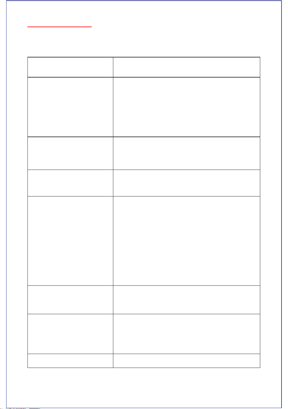
Faults and solutions
Problem
Solution
Troubleshooting
The following table lists some common faults and their solutions; if you can't resolve the fault, please contact
your dealer
No sound (Status: Receiver
RF doesn't display)
1. Check whether the power switches of the transmitter and
receiven are in the "ON" position
2. Check whether the positive and negative polarity of the battery
is disturbed
3. Check the antenna connection of the receiver to ensure that
there is no obstruction between the antenna and the
transmitter
1. Check if the receiver volume is the smallest
2. Check the connection between the microphone and other
audio equipment is whether normal or not
1. Check if the transmitter power is turned on
2. Change the microphone of the transmitter if necessary
1. Check whether the battery is installed firmly
2. Eliminate nearby radio frequency interference sources
3. If using a guitar or other musical instruments, check the
connection
4. Two transmitters may use the same frequency, find and close
one of them
5. The signal may be weak, re-adjust the position of the antenna,
as close as possible to the transmitter
6. Change other frequency
1. Eliminate RF noise sources
2. Re-adjust the receiver or antenna position
Replace the transmitter battery
1. Reposition the receiver and conduct a "walking" test to observe
the RF display
2. "If you find that there is a loss of sound, mark this point, and
avoid going there during the performance
No sound (Status: RF display is
normal, AF display is normal)
No sound (Status: RF display is
normal, AF display is abnormal)
When the transmitter is connected,
the received signal has noise or
interference of external sound
After the transmitter is turned off,
the receiver is noisy
The sound is occasionally lost during
the movement of stage performance
Cannot turn on the transmitter
11

Professional UHF Diversity Wireless Microphone
Name:M-9602

8
FCC STATEMENT
1. This device complies with Part 15 of the FCC Rules. Operation is subject to the following two conditions:
(1) This device may not cause harmful interference, and
(2) This device must accept any interference received, including interference that may cause undesired
operation.
2. Changes or modifications not expressly approved by the party responsible for compliance could void the
user's authority to operate the equipment.
NOTE: This equipment has been tested and found to comply with the limits for a Class B digital device,
pursuant to Part 15 of the FCC Rules. These limits are designed to provide reasonable protection against
harmful interference in a residential installation.
This equipment generates uses and can radiate radio frequency energy and, if not installed and used in
accordance with the instructions, may cause harmful interference to radio communications. However, there
is no guarantee that interference will not occur in a particular installation. If this equipment does cause
harmful interference to radio or television reception, which can be determined by turning the equipment off
and on, the user is encouraged to try to correct the interference by one or more of the following measures:
Reorient or relocate the receiving antenna.
Increase the separation between the equipment and receiver.
Connect the equipment into an outlet on a circuit different from that to which the receiver is connected.
Consult the dealer or an experienced radio/TV technician for help.
RF warning statement:
The device has been evaluated to meet general RF exposure requirement. The device can be used in
portable exposure condition without restriction.
Antenna and Cable Requirements (FCC Compliance)
To ensure compliance with the EIRP (Equivalent Isotropically Radiated Power) limits applicable to
unlicensed wireless microphones under FCC Part 15.236:
1.The transmitter is equipped with a dedicated, permanently attached internal spring antenna (Model: 555
Spring Antenna, Maximum Gain: -2.71 dBi). This antenna is not user-replaceable. Do not attempt to
modify or replace the antenna.
2. Only the original accessories supplied by the manufacturer should be used with the receiver unit. The
use of any unauthorized antennas or cables may cause the device to exceed the RF exposure and EIRP
limits, violating FCC regulations.
3. Changes or modifications not expressly approved by the party responsible for compliance could void the
user's authority to operate the equipment.