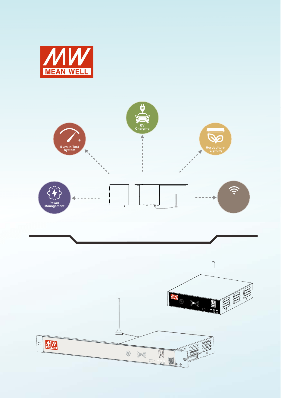
CMU3
Pragramable Intelligent Smart UI
Userʼs Manual
Multi-Industry General Purpose Smart Controller
Communication
NFC
ON
OFF
Internet
Status
USB-C
Reset
!
Internet
Status
USB-C
Reset
!
CMU3
ON
OFF

Preliminary
Preliminary
CMU3 is an advanced industrial controller designed to integrate industrial, commercial,
and residential systems, enhancing operational efficiency, energy management, and
system reliability. It provides User-defined Automation Control for flexible and
coordinated control of lighting, air conditioning, security, and other building systems.
Powered by the NEXUS APP platform, CMU3 enables integrated management and
monitoring of inverters, power supplies, PV systems, and third-party devices through a
unified interface. Its comprehensive energy management capabilities support real-time
monitoring of equipment power consumption, energy consumption reporting, and
performance optimization to improve overall energy efficiency. CMU3 also supports fault
diagnosis and system and device update notifications, helping users quickly identify
system issues and stay informed of the latest updates. With flexible control, integrated
management, and intelligent monitoring capabilities, CMU3 is an ideal solution for a
wide range of industrial, commercial, and residential applications.

Preliminary
Contents
1
1
2
2
2
3
4
6
7
7
7
8
8
9
10
11
12
13
14
15
16
17
17
17
17
17
18
18
20
21
21
25
26
26
29
32
1.Safety Guidelines
1.1 Safety Warnings and Cautions
2. Introduction
2.1 Model Encoding
2.2 Features
2.3 Specification
2.4 Mechanical specification
2.5 Supported models
3.User Interface
3.1 Panel Description
3.1.1 Panel Description-Front
3.1.2 Panel Description-Back
3.2 LED Indicator
3.3 DC IN Connector Pin No. Assignment
3.4 CANbus Connector Pin No. Assignment
3.5 RS-485 Connector Pin No. Assignment
3.6 RELAY Connector Pin No. Assignment
3.7 Prog. DIO Connector Pin No. Assignment
3.8 PMBus Connector Pin No. Assignment
3.9 LAN Connector Pin No. Assignment
3.10 Recommended Screwdriver, Wire and Torque Setting
4.Installation
4.1 Device Mounting
4.1.1 Desktop Type
4.1.1.1 Horizontal Mounting
4.1.1.2 Din Rail Mounting
4.1.2 Rack mount Type
4.2 Mini PCIe Installation
4.3 System Configuration
5.User Interface
5.1 Login Page
5.2 Home Page
5 3 Application. Card Management
5.3.1 Information Card Editing
5.3.2 Chart Card Editing
5.3.3 Connection Status Card Editing
Preliminary
Contents
2026.09Ver0
36
36
37
38
40
41
43
44
45
51
52
53
55
55
56
57
58
58
59
59
60
60
60
62
63
64
65
66
5.4 Comm Page
5.4.1 Comm Port Settings
5.4.1.1 LAN1/LAN2 (LAN Network) Settings
5.4.1.2 WLAN (Wireless Network) Settings
5 4 1 3. . . CAN1/CAN2 (CAN Bus Interface) Settings
5.4.1.4 RS-485(1)/RS-485(2) (Modbus Interface) Settings
5.4.1.5 REL1/REL2(Relay Output) Settings
5.4.2 Protocol Management
5.4.2.1 Protocol Creation Process
5.5 Manage Page
5.5.1 User Management
5.5.2 System Log
5.5.3 Application Management
5.5.3.1 Application Management Interface
5.5.4 System Status Monitoring
5.5.4.1 Time & Time Zone Settings
5.5.4.2 System Uptime / Users
5.5.5 LOG Management
5.5.6 System Update
5.5.7 System Image Replacement
6. Module
6.1 INV_Module (Inverter Module)
home page 6.1.1 NTN
6.1.2 System Settings: Charger Settings
Inverter Settings 6.1.3 System Settings:
6.1.4 Model Management: Link Status
6.1.5 Model Management: Monitoring Report
6.1.6 Shortcut Settings

1
Preliminary
1
1. Safety Guidelines
Risk of electrical shock and energy hazard, all failure should be examined by a
qualified technician. Please do not remove the case from the controller by
yourself.
Please do not install the contorller in places with high moisture, high ambient
temperature or under direct sunlight.
The input range is 10Vdc – 28Vdc, please do not connect the unit to voltages
out of the range.
The safety protection level of this is Class I. The unit's frame controller
ground ( ) must be properly connected to PE (Protective Earth).
1.1 Safety Warnings and Cautions
BSMI: For models certified as Class A equipment, should not be installed
or used in a residential environment to avoid electromagnetic
interference.
FCC Compliance Statement Compliance Notice:
This equipment has been tested and found to comply with the limits for a
Class A digital device, pursuant to part 15 of the FCC Rules. These limits are
designed to provide reasonable protection against harmful interference
when the equipment is operated in a commercial environment. This
equipment generates, uses, and can radiate radio frequency energy and, if
not installed and used in accordance with the instruction manual, may cause
harmful interference to radio communications. Operation of this equipment
in a residential area is likely to cause harmful interference in which case the
user will be required to correct the interference at his own expense.
This device complies with FCC Rules Part 15 rules.
Operation is subject to the following two conditions:
1. This device may not cause harmful interference.
2. This device must accept any interference received, including interference
that may cause undesired operation.
Changes or modifications that are not expressly approved by the
manufacturer could void the user's authority to operate the equipment.
To comply with FCC RF exposure compliance requirements, the device
should be located at a distance of at least 20cm from all persons during
normal operation. The antennas used for this product must not be co-
located or operated in conjunction with any other antenna or transmitter.
2
Preliminary
GCMU3
Series name
G: Global version
Blank: Chinese version
-R: Rack mount Type
Blank: Desktop Type
R-
2
2. Introduction
2.1 Model Encoding
2.2 Features
Panel-free design with external display connectivity & smartphone
APP control. (Download APP via QR code above.)
MW NEXUS-driven APP platform for integrated management of
inverters, power supplies, PV systems, and third-party devices
User-defined automation control for voltage/current adjustment,
power on/off control, and scheduled operations
Built-in PMBus, CAN bus, RS-485 (Modbus), and Ethernet
communication interfaces
Compatible with multiple network protocols, including Modbus TCP
and Web API
5 years warranty
3
Preliminary
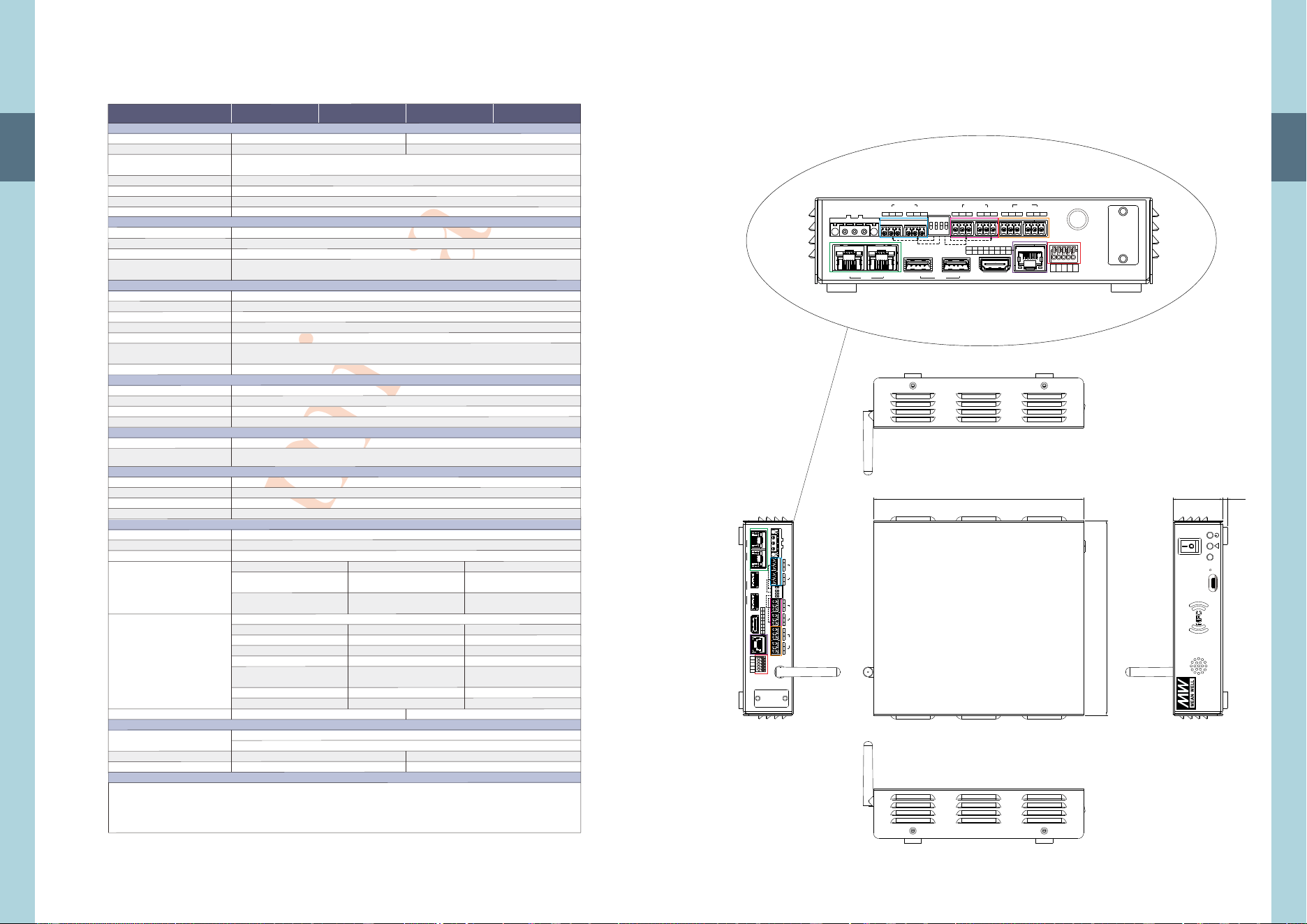
2.3 Specification
2
SPECIFICATION
VOLTAGE RANGE
EXPANSION SLOT
COMMUNICATION
WIRELESS COMMUNICATION
RELAY
MEMORY & STORAGE
CURRENT
PROGRAMABLE DIGITAL INPUT/OUTPUT
PUSH BUTTON
MONITORING TELEMETRY
THIRD-PARTY DEVICE SUPPORT Note.1
HARDWARE
INPUT
FUNCTION
COMMUNICATION PROTOCOLS
ETHERNET SUPPORTED
ENVIRONMENT
SAFETY & EMC (Note. 2)
OTHERS
REGULATORY COMPLIANCE
NOTE
HDMI FOR MONITOR CONNECTION
PROCESSOR
WORKING TEMP.
WORKING HUMIDITY
PMBUS
OTA (Over The Air)
LOG
NFC CONNECTIVITY
ETHERNET
CANBUS
RS-485
LANGUAGE
NETWORK
WEB SERVER
PROTOCOLS
STORAGE TEMP., HUMIDITY
VIBRATION
DIMENSION
MTBF
PACKING
-25 ~ +60℃
20 ~ 90% RH non-condensing
Customizable APP home page content and items. Refer to the user manual for details
Supports third-party device integration via compatible communication interfaces and protocols. Refer to the user manual for details
PMBus v1.1
Firmware updates via Ethernet for system firmware and application software
1.Data log (device status) 2.Event log (alarm, AC anomalies, etc.) 3.System log (system status, warnings, version information, etc.)
4.Log interval can be set from 1 minute to 60 minutes 5.Selectable log options (ALL, voltage, current, etc.)
Built-in web interface for system monitoring, configuration, and operation status
Supports NFC for reading device parameters using compatible NFC-enabled devices
CANbus 2.0B
Modbus RTU
English, Traditional Chinese / Simplified Chinese / Japanese (Other languages are available upon request.)
Support IEEE802.3, 10/100base network x 2
TCP/IP, NTP, Modbus TCP
Built-in MEAN WELL's NEXUS platform for displaying system status, parameters, and recorded or downloaded data
For details of additional functions, refer to the user manual
-40 ~ + ℃,10~95% RH non-condensing80
10 ~ 500Hz, 2G 10min./1cycle, 60min. each along X, Y, Z axes
CMU3G: 694.6K hrs min. Telcordia SR-332 (Bellcore) ; 85.45K hrs min. MIL-HDBK-217F (25℃)
CMU3G-R: 694.6K hrs min. Telcordia SR-332 (Bellcore) ; 85.5K hrs min. MIL-HDBK-217F (25℃)
1.03Kg; 10pcs/11.3Kg/1.47CUFT
Desktop: 192*178*45.5mm (L*W*H) Rack mount: 482*186.6*44.5mm (L*W*H)
2.04Kg; 6pcs/13.2Kg/2.49CUFT
IEC62368-1 approved
IEEE 802.11 b/g/n
2.4 GHz
10 ~ 28Vdc
Mini PCIe × 1 (Reserved; available upon request. Please refer to user manual and contact MEAN WELL for customization.)
1.RS-485(Modbus)*2 2.CANbus*2 3.PMbus*1 4.Ethernet*2 5.USB2.0: TYPE-C*1 TYPE-A*2、
1.Wi-Fi (802.11b/g/n) 2.4 GHz 2.NFC for MW App
1.5A / 24Vdc
HDMI 2.0 interface
Rockchip RK3568J
HDMI 1.4 interface
NXP i.MX 8M Plus Dua
2 Groups, Relay Contact Rating: 30 VDC / 1 A
Programmable via User-defined Automation Control or the APP platform
4 configurable digital I/O channels; digital outputs use open-collector architecture
1. ON/OFF button : Enables or disables all connected devices (PSUs, chargers, and inverters) simultaneously
2. Reset button: Press to reboot CMU3 and restore all configurations to factory default settings. Refer to the user manual for details.
SAFETY STANDARDS
WIRELESS STANDARD
FREQUENCY BAND
EMC EMISSION
EMC IMMUNITY
CMU3 CMU3-R CMU3G CMU3G-R
https://www.meanwell.com//Upload/PDF/EMI_statement_en.pdf
※:https://www.meanwell.com/serviceDisclaimer.aspx
1. RAM : 2G(DDR4) 2. eMMC : 16G
Parameter
Parameter
Conducted
Radiated
BS EN/EN55035(CISPR35)
Standard
Standard
BS EN/EN61000-4-2
BS EN/EN61000-4-3
BS EN/EN61000-4-4
BS EN/EN61000-4-5
BS EN/EN61000-4-6
BS EN/EN61000-4-8
BS EN/EN55032(CISPR32),CNS 15936,
GB/T 9254.1, FCC
BS EN/EN55032(CISPR32),CNS 15936,
GB/T 9254.1, FCC
Test Level / Note
Test Level / Note
Level 3, 8KV air ; Level 2, 4KV contact
Level 2, 3V/m
Level 1, 0.5KV
Level 1, 0.5KV/Line-Earth ;
Level 2, 0.5KV/Line-Line
Level 2, 3V
Level 1, 1A/m
Class B
Class A
ESD
Radiated
EFT / Burst
Surge
Conducted
Magnetic Field
CE (RED) / FCC / NCC / SRRC approved CE (RED) / FCC / NCC approved
4
Preliminary
Unit: mm
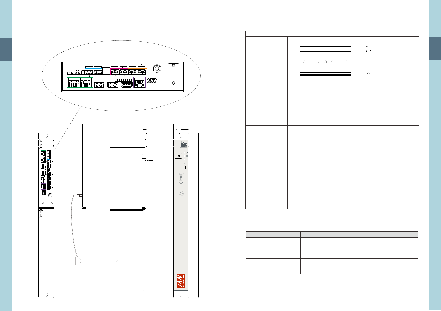
Desktop Type
2.4 Mechanical specification
2
ON
45.5 4.3192
178
OFF
!
8
8
1
1
1
8
USB
1
2
HDM I
PMB us
Exp ansio n Slot
Pro g. I/O
1
LAN
2
1 2 3 4
G
DIO DI O
DIO
DIO
FG
-Vi n
+Vi n
10~ 28Vdc
CAN Bus
1
2
H L G H L G
120Ω
RS- 485
1
2
D+ D- G D+ D- G
Rel ay
1
2
NO NC C NO NC C
ANT
1 2 3 4 5 6 7 8
- - - -
R.C.
SDA
SCL
G
G=GN D_AUX
C=CO M
DC IN
8 8
1
1 1
8
USB
1
2
HDMI
PMBus
Expansion Slot
Prog. I/O
1
LAN
2
1 2 3 4
G
DIO DIO
DIO
DIO
FG
-Vin
+Vin
10~28Vdc
CANBus
1
2
H L G H L G
120Ω
RS-485
1
2
D+ D - G D + D- G
Relay
1
2
NO NC C NO NC C
ANT
1 2 3 4 5 6 7 8
- - - -
R.C .
SDA
SCL
G
G=G ND_ AUX
C=C OM
DC IN
5
Preliminary
2
Unit: mm
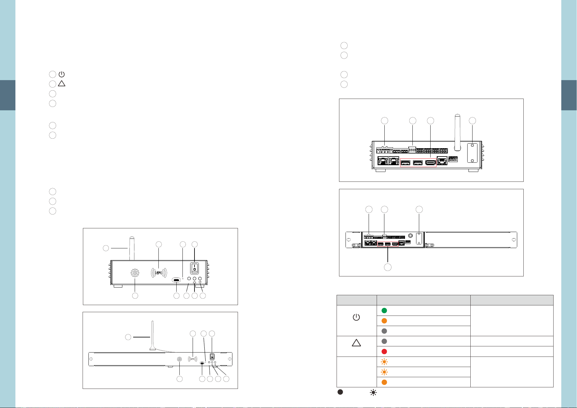
Rack mount Type
ψ7.3
10
186.6
3.4
67.6
15
482
8.5
465
3.2
22.7
44.5
Cable Length:1000 5mm±
Antenna
!
CMU3
8 8
1
1 1
8
PMB us
Exp ansio n Slot
Pro g. I/O
1 2 3 4
G
DIO DIO
DIO
DIO
Rel ay
2
C NO NC C
ANT
USB
1
2
HDM I
1
LAN
2
FG
-Vi n
+Vi n
10~ 28Vdc
CAN Bus
1
2
H L G H L G
120Ω
RS- 485
1
2
D+ D - G D+ D - G
1
NO N C
1 2 3 4 5 6 7 8
- - - -
R.C.
SDA
SCL
G
G=GN D_AUX
C=CO M
DC IN
8
8
1 1
USB
1
1
LAN
2
FG
-Vin
+Vin
10~28Vd c
CANBus
1
2
H L G H L G
120Ω
G=GND_ AUX
C=COM
DC IN
1
8
PMBus
Expansi on Slot
Prog. I/O
1 2 3 4
G
DIO DIO
DIO
DIO
Relay
2
C NO N C C
ANT
2
HDMI
RS-485
1
2
D+ D- G D + D- G
1
NO N C
1 2 3 4 5 6 7 8
- - - -
R.C .
SDA
SCL
G
6
Preliminary
Accessory List Single Unit ( )
2.5 Supported models
2
←
←
DC-AC Inverter
AC DC Inverter
AC-DC Power
Supply
NTN-5K
BIC-5K, NTG-7K5, NTG-20K
BIC-2200, HEP-1000, HEP-2300, MSP-1600, NSP-1000,
NSP-1600,NSP-2400, NSP-3200, PHP-3500, RCP-2000,
RSP-1600, SHP-10K, SHP-30K, UHP-1500, UHP-2500
CategoryApp icon Supported Model
Note: For models not listed in above table, please contact MEAN WELL sales team.
Available
Coming soon
Coming soon
Status
Din Rail Plate
For desktop version
DC IN Connector
DINKLE 2ESDVM-03P
Communication
Connector
DECA MX422-25406
1pcs/per model
1pcs/per model
6pcs/per model
1
No. QuantityItem
2
3
7
Preliminary
3.1.1 Panel Description-Front
3
3.User Interface
3.1 Panel Description
A
B
C
D
E
F
G
H
I
Power Indicator: Used to display whether the CMU3 is powered on.
Alarm Indicator: The indicator will light up when an abmomral condition occurs.
Internet Status Indicator.
System Swtich: 0 (OFF): Disables the outputs of all connected products directly through the communication interface.
USB-C ports.
1 (ON): Output control is determined by the module page. The corresponding ON/OFF commands
are then transmitted to the connected products through the communication interface.
Reset Button.: Press and hold the Reset Button for 10 seconds to restore the factory default settings.
NFC Detection Area.
Speaker.
Antenna.
NOTE: The System Swtich canno be used to turn the controller off.
!
Internet
Status
Desktop Type
Rack mount Type
A
BH E
DG
I
C
A
BH E
DG F
I
C
F
!
Internet
Status
!
Internet
Status
Deletes all non-default communication protocols.
Deletes all user accounts and user settings.
Clears the Data Log and Event Log.
NOTE: Restoring the factory default settings will reset the network IP address to its
default value, which may cause the current connection to be lost. Please
ensure that you understand the impact before proceeding with the factory
reset.
8
Preliminary
A
B
C
D
DIN (DC input): DC input range: 10 – 28VDC.
DIP Swtich for the Termination Resistors: Used to set the termination
resistors for the CAN bus and Modbus interfaces.
USB and HDMI: Used to connect peripheral devices.
Expansion Slot: Used for functional expansion; supports mini PCIe.
Desktop Type
Rack mount Type
3
3.1.2 Panel Description-Back
3.2 LED Indicator
LED Status Description
=Power connected
=Booting
=No power connected
Power Indicator
The power indicator lights up orange
when the system is first powered on.
Once the system is ready and operating
normally, the indicator turns steady
green.
=Normal operating
=Abnormal status
Alarm Indicator
Ethernet connection status.
CMU3 or Rack Power in abnormal conditions.
CMU3 is in a normal condition.
!
Internet Status
A
B
D
A B D
C
C
= Internet unstable
x 3 times repeatedly = AP Mode
=Internet stable
=steady =flashing
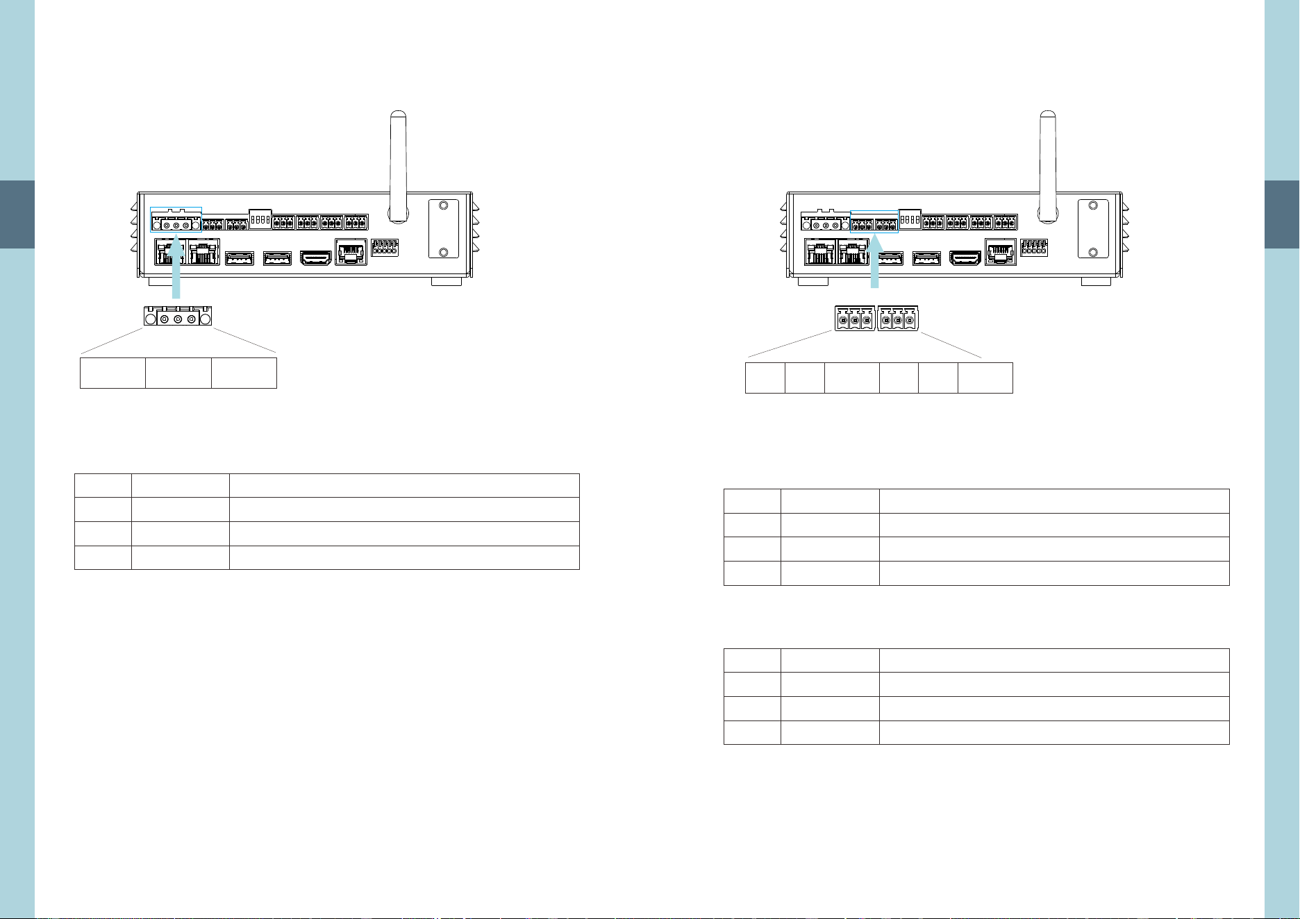
9
Preliminary
3
1
3
Pin No.
Connect Pin No. Assignment: or equivalentDINKLE 2ESDVM-03P
1
2
3
Function
FG
+Vin
-Vin
Description
Frame Ground (Protective Earthing)
DC power supply positive input
DC power supply negative input
+Vin-VinFG
31
3.3 DC IN Connector Pin No. Assignment
DC IN
10
Preliminary
3
Pin No.
Pin No.
CANbus1
CANbus2
1
1
2
2
3
3
Function
Function
CAN-H
CAN-H
CAN-L
CAN-L
GND_AUX
GND_AUX
Description
Description
High-level CAN bus line (Note 1)
High-level CAN bus line (Note 1)
Low-level CAN bus line (Note 1)
Low-level CAN bus line (Note 1)
CMU3G Auxiliary Power Reference Ground (Note 2)
CMU3G Auxiliary Power Reference Ground (Note 2)
3 31 1
3 3
1 1
CAN-H CAN-H
CAN-L CAN-L
GND_AUX GND_AUX
Note 2: GND_AUX is the reference ground for the CMU3 auxiliary power supply
and is isolated from the DC power supply (+Vin & -Vin).
Note 1: Isolated signal, with GND_AUX as reference
3.4 CANbus Connector Pin No. Assignment
Connect Pin No. Assignment: or equivalentDECA MX422-25406
CANbus1 CANbus2
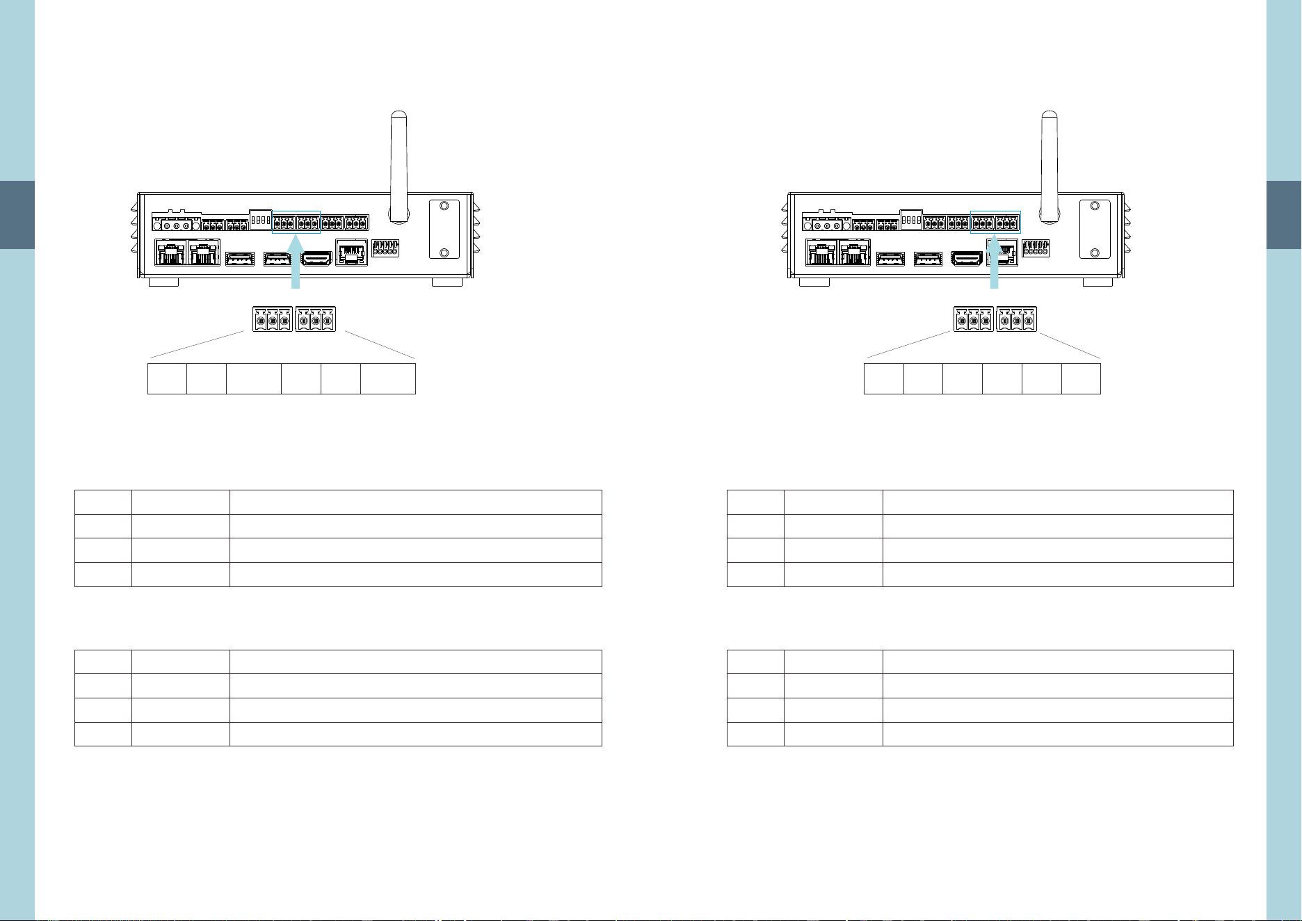
11
Preliminary
3
1
1
2
2
3
3
D+
D+
D-
D-
GND_AUX
GND_AUX
RS-485 Differential Signal Plus (Non-inverting)(Note 1)
RS-485 Differential Signal Plus (Non-inverting)(Note 1)
RS-485 Differential Signal Minus (Inverting)(Note 1)
RS-485 Differential Signal Minus (Inverting)(Note 1)
CMU3 Auxiliary Power Reference Ground(Note 2)
CMU3 Auxiliary Power Reference Ground(Note 2)
3 31 1
3 3
1 1
D+ D+D- D-
GND_AUX GND_AUX
3.5 RS-485 Connector Pin No. Assignment
Connect Pin No. Assignment: or equivalentDECA MX422-25406
Note 2: GND_AUX is the reference ground for the CMU3 auxiliary power supply
and is isolated from the DC power supply (+Vin & -Vin).
Note 1: Isolated signal, with GND_AUX as reference
Pin No.
Pin No.
Function
Function
Description
Description
RS-485(1)
RS-485(2)
RS-485(1) RS-485(2)
12
Preliminary
3
3 31 1
3 3
1 1
Relay1
-COM
Relay2
-COM
Relay1
-NC
Relay2
-NC
Relay1
-NO
Relay2
-NO
Relay1
Relay2
1
1
2
2
3
3
Relay1-NO
Relay2-NO
Relay1-NC
Relay2-NC
Relay1-COM
Relay2-COM
Normal-open contact of programmable relay1
Normal-open contact of programmable relay2
Normal-close contact of programmable relay1
Normal-close contact of programmable relay2
Common for relay1 NO/NC contact
Common for relay2 NO/NC contact
3.6 RELAY Connector Pin No. Assignment
Connect Pin No. Assignment: DECA MX422-25406 or equivalent
Pin No.
Pin No.
Function
Function
Description
Description
Relay1
Relay2

13
Preliminary
3
1
2
3
4
5
DIO0
DIO1
DIO2
DIO3
GND_AUX
Programmable digital input/output (Note 1)
Programmable digital input/output (Note 1)
Programmable digital input/output (Note 1)
Programmable digital input/output (Note 1)
CMU3G Auxiliary Power Reference Ground (Note 2)
3.7 Prog. I/O Connector Pin No. Assignment
Connect Pin No. Assignment: or equivalent DINKLE 141R-05
Pin No. Function Description
Note 2: GND_AUX is the reference ground for the CMU3 auxiliary power supply
and is isolated from the DC power supply (+Vin & -Vin).
Note 1: Isolated signal, with GND_AUX as reference
1 5
DIO0 DIO1 DIO2
GND_AUX
1
DIO3
5
Prog. I/O
14
Preliminary
3
Pin No.
1,2,3,5
4
6
7
8
Function
NC
CONTROL
SDA
SCL
GND_AUX
Description
Not use
Remote ON/OFF control pin (Note 1)
Serial Data used in the PMBus interface (Note 1)
Serial Clock used in the PMBus interface (Note 1)
CMU3G Auxiliary Power Reference Ground (Note 2)
3.8 PMBus Connector Pin No. Assignment
Connect Pin No. Assignment: RJ45 8 position
Note 2: GND_AUX is the reference ground for the CMU3 auxiliary power supply
and is isolated from the DC power supply (+Vin & -Vin).
Note 1: Isolated signal, with GND_AUX as reference
PMBus
1 8
1 8
SDA
GND_AUX
NC NC SCLNC CONTROLNC
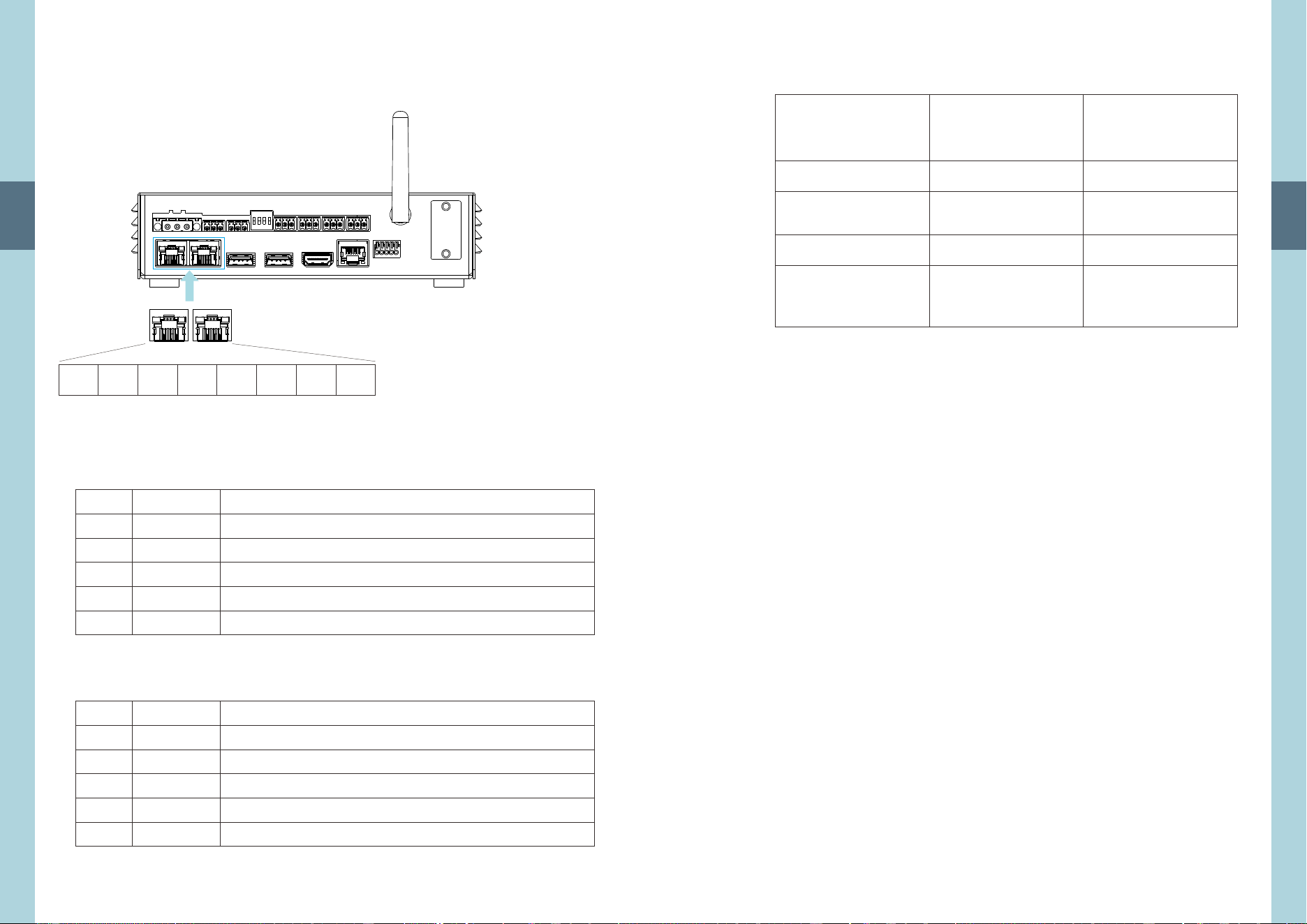
15
Preliminary
8
TX+
Pin No.
Pin No.
1
1
2
2
3
3
4,5,7,8
4,5,7,8
6
6
Function
Function
TX+
TX+
TX-
TX-
RX+
RX+
NC
NC
RX-
RX-
Description
Description
Transmit data used in the Ethernet interface
Transmit data used in the Ethernet interface
Transmit data used in the Ethernet interface
Transmit data used in the Ethernet interface
Receive data used in the Ethernet interface
Receive data used in the Ethernet interface
Receive data used in the Ethernet interface
Receive data used in the Ethernet interface
Not used
Not used
1
11 88
TX-RX-NC NC RX+NC NC
3.9 LAN Connector Pin No. Assignment
3
Connect Pin No. Assignment: RJ45 8 position
Connect Pin No. Assignment: RJ45 8 position
LAN( 1)
LAN(2)
LAN( 1) LAN( 2)
16
Preliminary
Type The input connector
CANbus1/2
MODbus1/2
Relay1/2
Recommended
tightening
torque(N.m)
Screwdriver
Wire stripping
length(mm)
AWG 12-20 14-28
7-8 6-7
M2.5 M2
0.4-0.5 0.2-0.25
3.10 Recommended Screwdriver, Wire and Torque Setting
3
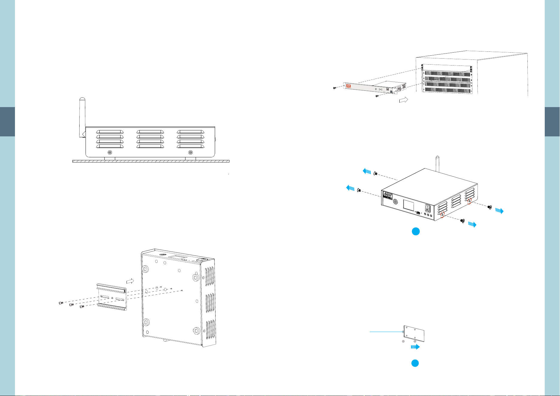
17
Preliminary
Horizontal Mounting
Din Rail Mounting
4.1.1 Desktop Type
4.1.1.1 Horizontal Mounting
4.1.1.2 Din Rail Mounting
M3 Nylok Screw*3
(Recommended
mounting torque: 6~8Kgf-cm)
4
4.Installation
4.1 Device Mounting
18
Preliminary
4.1.2 Rack mount Type
M5*12mm
!
CM
U3
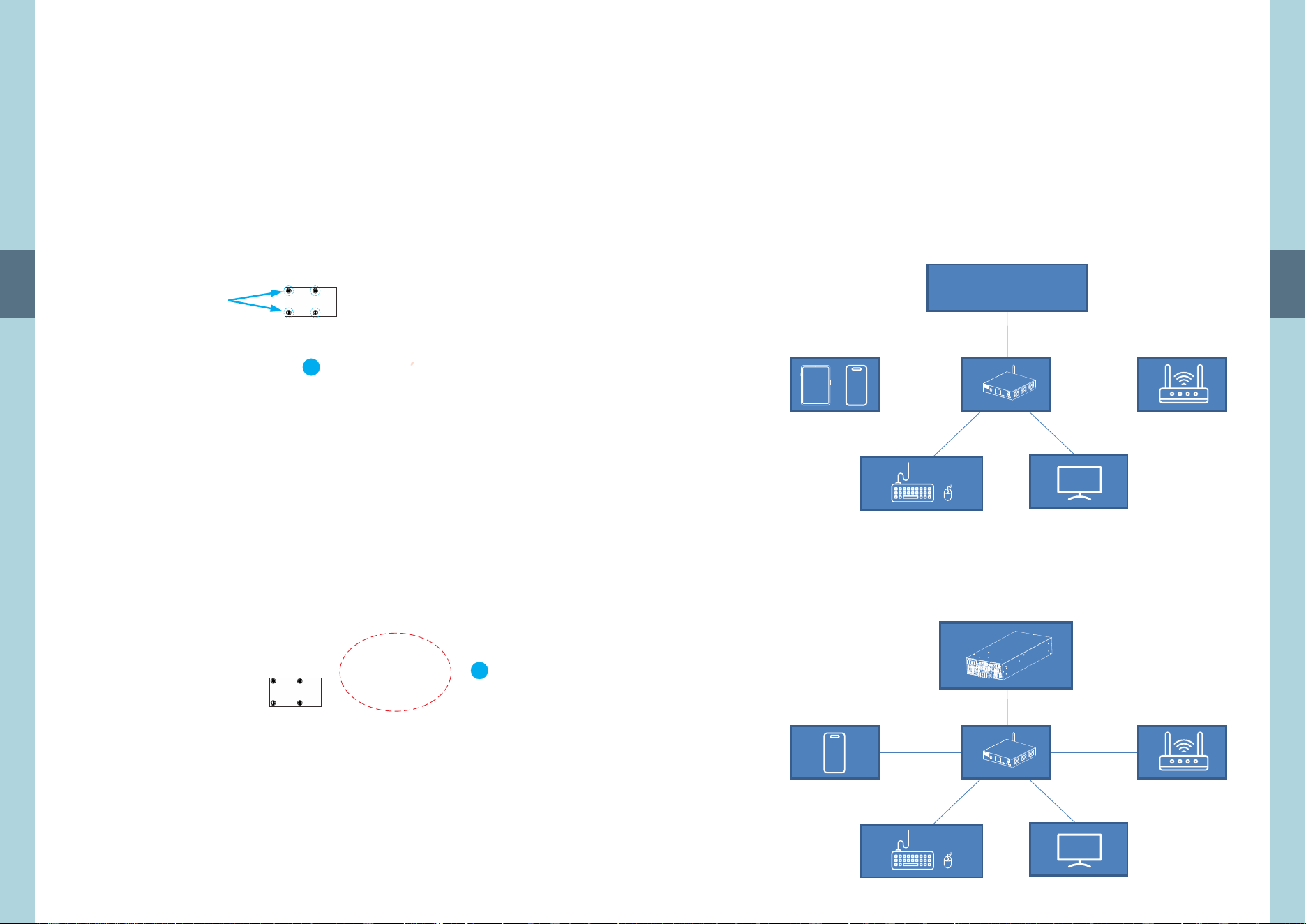
1.The Mini PCIe socket is located on the mainboard. Remove the cover first
to access the socket.
2. insert the Mini PCIe card into the connector.After the cover is removed,
Insert the
card at an angle
2
1
4.2 Mini PCIe Installation
4
19
Preliminary
3.Push down on the other end of the Mini PCIe card and secure the card
on the mainboard with the provided mounting screw.
4. If the mini PCIe card comes with an additional accessory, secure it in the
areas marked in red.
If not, simply reinstall the cover to complete the installation.
(Recommended mounting torque: 4~5.5Kgf-cm)
M2 mounting
screw.
(Recommended
mounting torque:
1.79~4.28Kgf-cm)
3
4
4
20
Preliminary
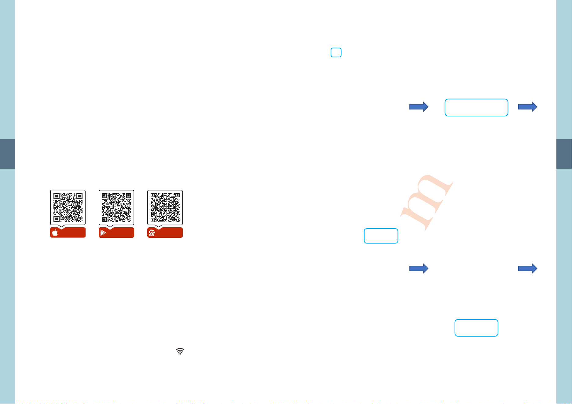
The CMU3 can be flexibly connected to corresponding devices to form a
complete system. Its communication interfaces are highly versatile,
supporting common protocols such as PMBus, CAN bus, and Modbus, for
controlling and monitoring relevant equipment (for example, Mean Well
power products). In addition, the CMU3 can connect to smartphones,
tablets or computers via Ethernet, Wi-Fi, or NFC to enable remote
monitoring, or use interfaces such as HDMI and USB to establish an on-site
monitoring platform.
Using the NTN-5K Energy Monitoring System as an example, the CMU3
can control and monitor the NTN-5K via CAN bus, displaying relevant
information on a mobile device. The following provides an example
system description for this setup.
Devices
(e.g. MeanWell products)
Ethernet
Ethernet
PMBus/ CAN bus/ Modbus
CAN bus
WiFi/NFC
WiFi
HDMI
HDMI
USB
USB
NTN-5K
4
4.3 System Configuration
21
Preliminary
During initial power-up, the CMU3 requires IP address configuration to
establish a network connection for remote monitoring and control. Two
configuration methods are available:
Method 1: Direct configuration via a monitor and keyboard.
Method 2: Configuration using a mobile application, as described below.
The CMU3 is a highly configurable controller that allows users to customize
monitoring parameters and display pages. Once access to the CMU3
operating interface, please refer to the online user manual for completing
the remaining setup for the required monitoring and control functions.
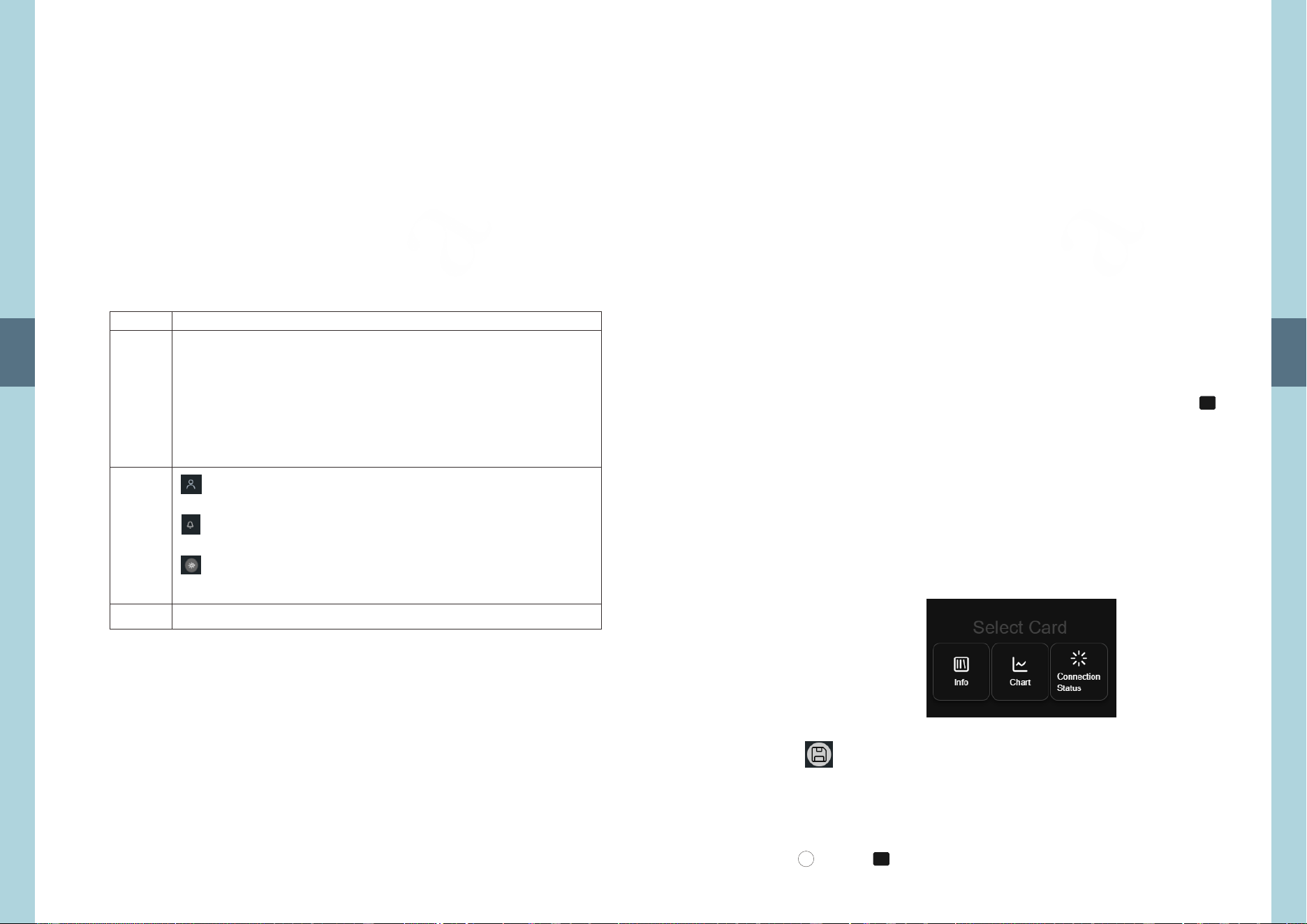
● Preparation
Your mobile device must support NFC and have the MEAN WELL APP
installed. If the app is not yet installed on your device, please scan the
following to download: iOS APP | Android APP | Android APP
● Compatible Mobile Devices
Android: Android OS 4.1 (API 16) or later.
iPhone: iOS 12 or later.
● Configuration Steps
1. Download the MEAN WELL APP on your mobile device and enable the NFC
function.
2. Open the app and then tap "CMU3" button to start scanning for tags.
Location of "CMU3" button: tap the "manual icon" in the upper left corner
on the main page of the app, tap "Installation Manual/APP" button you
will see it just sits on the bottom.
3. Hold the device near (< 5cm) the NFC Tag of the controller. For iPhone,
hold the top-center of your phone onto the tag. For Android, place
backside-middle of the phone onto the Tag. If it doesn't work you may
refer to its instruction manual.
iOS APP Android APP Android APP
NFC
5.User Interface
5.1 Login Page
5
22
Preliminary
5

23
Preliminary
5
NOTE:
1.MW APP會記錄已設定的設備資訊,後續可以MW APP快速連接至已設定過的
CMU3。
2.「初次連線」適用於首次使用的 CMU3。CMU3 預設為 AP 模式,使用「初次連
線」功能可讓 MW APP 與 CMU3 連線至同一網路。如果CMU3 的網路設定已變
更,請使用「快速連線」功能。若連線失敗,請確認使用的行動裝置是否與
CMU3 連線至同一網路。
24
Preliminary
● Login Page
The login page will be displayed when accessing the CMU3 unit.
First-time users are required to apply for an account.
NOTE:
1. The CMU3 starts in AP Mode by default. Connect your mobile device to its Wi-Fi network
to begin setup, the default WiFi name is: CMU3_AP_xxxx. The password is: 12345678. After
connecting, the default homepage URL is: 192.168.4.1:5039.
2. If the default IP has been modified, the homepage URL must include the new IP followed
by :5039. For example: if the IP is 192.168.200.105, then the homepage URL would be
192.168.200.105:5039.
Display Language
The CMU3 supports English, Traditional Chinese, and Simplified Chinese. The CMU3 will
automatically adapt to the appropriate language based on the browser you are using. If the
browser language is not supported, the CMU3 will default to English. On mobile devices,
Android uses the browser's language settings, while iOS uses the system language or the
browser's preferred language settings to determine the display language.
5
● iOS devices: The NFC function is enabled by default, and no additional
user settings are required. The NFC antenna is typically located at the top
of the device.
● Android devices: The NFC function must be manually enabled in the
system settings. As NFC antenna placement varies by brand and model,
there is no standard location.
● If any NFC-related issues occur during operation, it is recommended to
contact the device manufacturer or refer to the user manual for the
specific model.
25
Preliminary
After logging in, users can access the home page. On the home page,
users can perform functions such as app search, notification review, and
mode switching.
Apps or related applications can be installed through Application Management
on the Manage page. For more details, please refer to Section 5.5.3.
App: This is the home page, where you can search for modules, view the event log,
switch light/dark mode, and perform other related functions.
Comm: Used to manage the CMU3 communication protocols, including importing
and editing protocols. Refer to Section 5.4 for details.
Manage: This page allows you to manage and configure user Management, System
Logs, Application Management, Resource Management & Monitoring, LOG
Management, System Update, Power Product Updates, and system image
replacement, Audio Settings, Background System Settings and Custom
Footer Links. Refer to Section 5.5 for details.
5.2 Home Page
No.
1
2
3
Description
Member Center: Used to manage personal information,
such as changing the password.
Notifications: Event log that records the operating status
of the app.
Mode Switch: Toggle between light mode and dark mode.
Logout Button: Logs out the current user.
App search. Supports both basic search and advanced search.
Single-click (tap once) the app image to open.
5
26
Preliminary
5
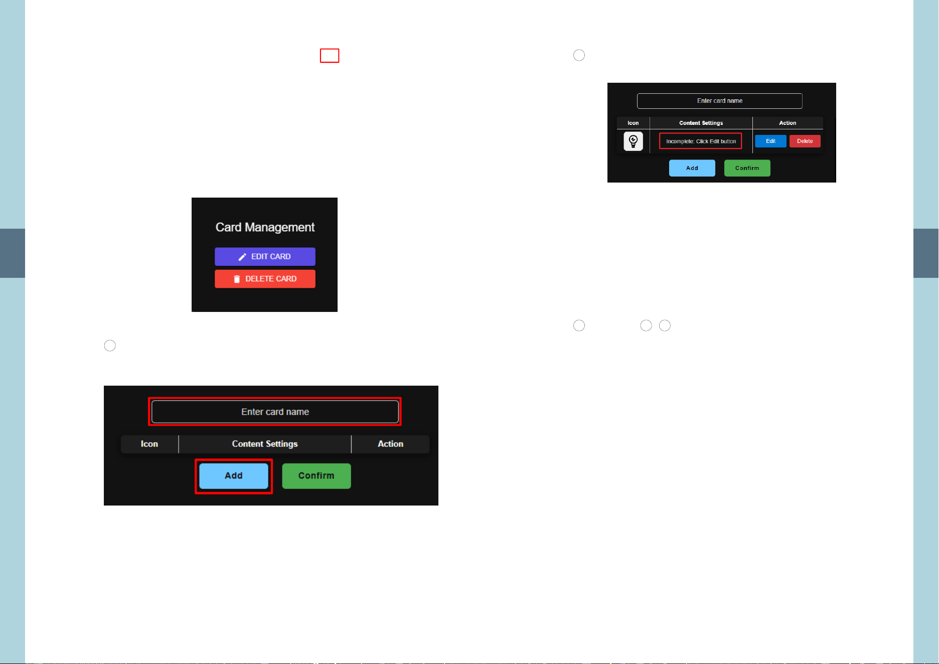
On , users can freely customize the module pages, such as INV_module
information, charts, and connection status to create a personalized
interface. The editing functions are located in the upper-right corner of
the page.
5.3.1 Information Card Editing
After adding an information card, the new card will appear on the page.
Click the icon in the upper-right corner of the card to select
" " or " "EDITCARD DELETE CARD
Edit Cards:Used to enable/disable the editing mode. When
Edit Cards is enabled, the Add Card, Restore Default
Cards and Save Card Layout options will appear on
the page. Cards on the page will display the icon,
indicating these cards are allowed to be modified.
Click the edit mode icon again to exit edit mode.
Add Card: Used to add new cards. Three types of cards are
available: Information, Chart, and Connection
Status.
Save Card Layout: Used to save the edited page. After making
changes, be sure to click this icon to avoid
losing any modifications.
: Restore the default card configuration Restore Default Cards
and overwrite all current card settings.
...
...
1
5.3 Application Card Management
27
Preliminary
5
After selecting , you can name the card, add contents and EDIT CARD
change the icons.
2
28
Preliminary
5
After adding content, click Edit button to open the “Value and
Command Settings” window.
Repeat the - steps to complete cards with specific
functionality. Example: A card displaying the AC input/output
voltage and frequency of an NTN-5K-224CAN (address 0).
Note: Up to 4 different items can be displayed simultaneously.
3
4 2 3
29
Preliminary
5
5.3.2 Chart Card Editing
After adding a chart card, the new card will appear on the page.
Click the icon in the upper-right corner of the card to select
"EDITCARD" or "DELETE CARD".
After selecting , you can name the card and add EDIT CARD
curve data.
...
1
2
30
Preliminary
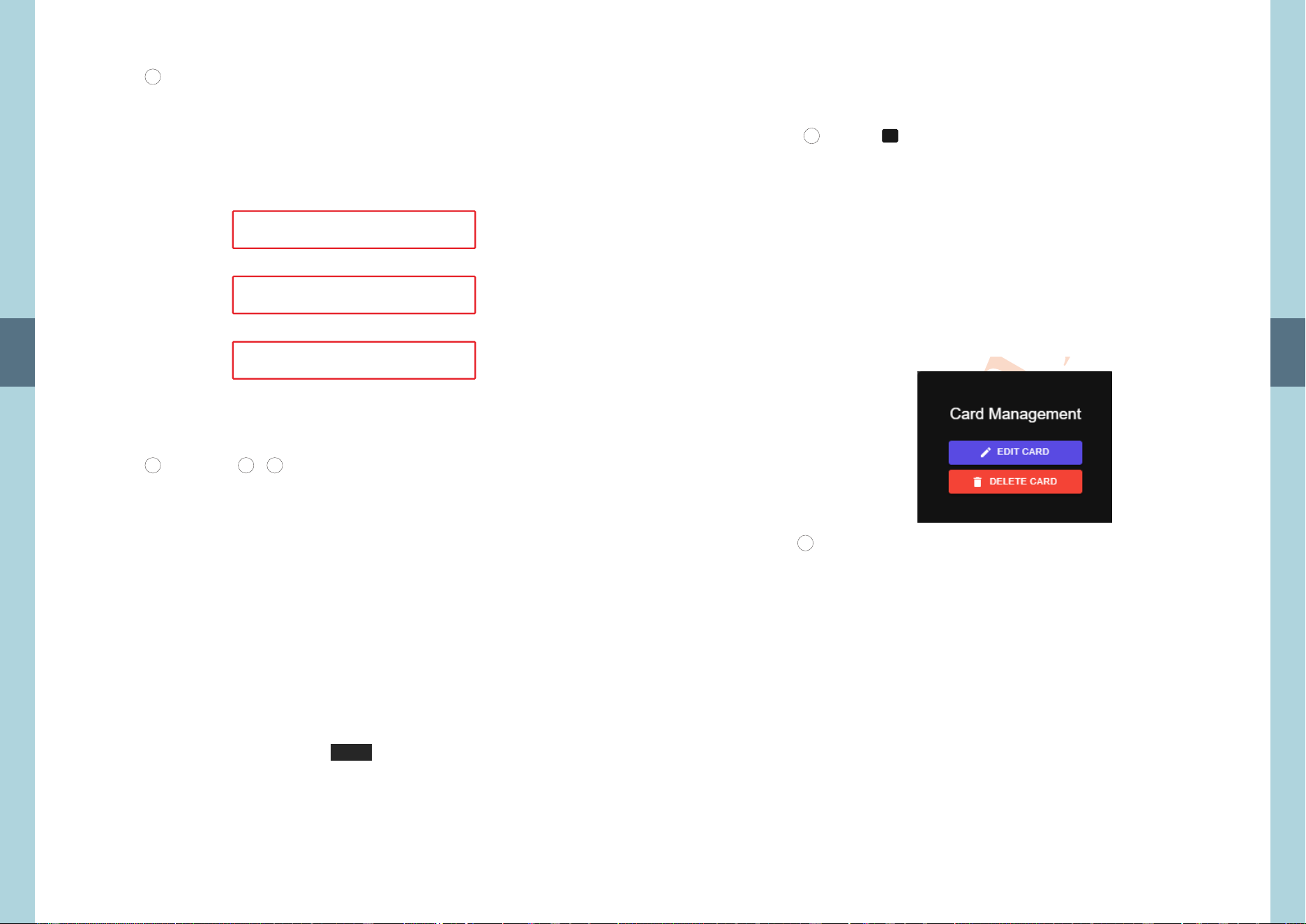
To configure the chart curves, click the card to enter a Select
Device and Command window and choose the desired device
and parameters to display.
5
3
31
Preliminary
After selection, a window will appear where Display Settings
you can edit the curve name, set displaying axis and select data-
color.
Repeat the - steps to complete a card with specific
functionality.Example: A chart displaying battery voltage and
current curves of the NTN-5K.
Note: Up to 2 curves can be displayed simultaneously.
5
4
5 2 4
Time
32
Preliminary
5
5.3.3 Connection Status Card Editing
After adding a connection status card, the new card will appear on
the page.
Click the icon in the upper-right corner of the card to select
" " or "DELETE CARD".EDITCARD
After selecting DELETE CARD, you can change the card icon and
name the card.
...
1
2

33
Preliminary
Once completed, the card will display the connection status between
the NTN-5K and other devices.
5
3
5.3.4 Card Movement
In the editing mode, application cards can be repositioned to suit
your preferences.
Desktop Version:
1 Click and drag the desired card.
34
Preliminary
2 Release the card when it reaches the desired position.
Mobile Version:
1 Tap Order in the red box
5
35
Preliminary
2 The page will display all editable cards. Then tap to set the
cards to the desired position.
5
36
Preliminary
5
The Comm page is used to configure the CMU3's communication
protocols, channels, and thresholds with external devices to ensure
smooth and secure data exchange.
5.4 Comm Page
No.
2
1
Description
The Protocol Management page is used to edit and import
communication protocols from third party's devices.
The CMU3 supports various communication interfaces
(including CAN bus, RS-485, PMBus, Ethernet, etc.) and
network protocols (e.g., Modbus TCP, Web API, Matter).
The icons on this page correspond to the physical
communication ports on the CMU3. Click an icon to configure
the protocol settings for that port.
5.4.1 Comm Port Settings
Users can configure the communication port by selecting the
corresponding port icon. Parameters such as the baud rate can be
adjusted according to specific requirements. Please refer to the
description of each port for detailed information.
1
2

37
Preliminary
5.4.1.1 LAN1/LAN2 (LAN Network) Settings
This page is used to configure the accessing parameters of LAN1/ LAN2,
including IP address, DNS servers, and routing rules.
1. Interface Control
Enable this interface
o ON ( ): Enable LAN and start packet transmission
o OFF ( ): Disable the port
2. Interface Name
Interface Name: Read-only
Note: For optional user-defined description (e.g., "Internal Network",
"External Network")
3.IP Acquisition Method
DHCP (Auto)
o Suitable for environments connected to standard routers or
switches. The system will automatically request an IP address from a
DHCP server.
Static (Manual)
o Suitable for server environments or specific network segments that
require a fixed IP address. When selected, the following fields must
be configured:
o IPv4 Address: Enter the assigned static IP address (e.g., 192.168.1.1)
o Subnet Mask: Enter the subnet mask to define the network range
(e.g., 255.255.255.0)
5
38
Preliminary
5
5.4.1.2 WLAN (Wireless Network) Settings
o Gateway: Enter the default gateway IP address, which is usually the
router's IP (e.g., 192.168.1.54).
4.DNS Server Settings
Configure to ensure the system can Domain Name System (DNS) servers
translate domain names (e.g., www.google.com) into IP addresses.
DNS 1: Primary DNS server IP (e.g., 203.79.200.1).
DNS 2 (Optional): Secondary DNS server, used when the primary
server is unavailable.
5. Routing Settings (Critical Setting)
Set as as Default Gateway :
o Function: When enabled, all traffic outside the local network (i.e.,
Internet traffic) will be routed through this interface by
default.
o Note: Only one network interface can be set as the default gateway.
If multiple interfaces are used (e.g., Ethernet 1, Ethernet 2, or
Wi-Fi), ensure that this option is enabled only on the primary
external connection interface. Otherwise, routing conflicts
may occur, resulting in network connectivity issues.
6. Save All Settings
After confirming that all configurations are correct, click this button to
apply the changes. The network connection may briefly reconnect.

39
Preliminary
5
This page is used to configure the operating mode and connection parameters of
the wireless network interface (Wi-Fi).
1. Interface Control
Enable WLAN:
o ON ( ): Enable WLAN and start packet transmission
o OFF ( ): Disable the port
2. Operation Mode
Wi-Fi Mode (Connect to existing hotspot)
o Function: Connects to an existing Wi-Fi router or hotspot.
AP Mode (Create hotspot)
o Function: operates as an access point allowing wireless-capable devices
(e.g., smartphones, tablets) to connect to the device.
o Use Case: Suitable when no network is available on-site or for initial setup
using the MW App.
3. Wi-Fi Mode Settings (Only available in Wi-Fi Mode)
SSID: Enter the Wi-Fi network name to connect to
o Scan Button: Click Scan to display a list of available nearby Wi-Fi " "
networks
Password: Enter the Wi-Fi password
Auto Reconnect:
o When enabled, the system will automatically attempt to reconnect if the
connection is lost due to unstable signals
4. IP Assignment Method
Configure how the IP address is assigned after connecting to Wi-Fi:
DHCP (Auto obtain IP)
o The router automatically assigns an IP address
Static IP (Manual sepcify)
o Suitable for environments requiring a fixed IP
o IP Address: Enter the assigned static IP (e.g., 192.168.1.1)
o Subnet Mask: Define the network range (e.g., 255.255.255.0)
o Default Gateway: Enter the router IP (e.g., 192.168.1.254)
o Primary / Secondary DNS: Domain Name System (DNS) server
5. Routing Settings
As Default Gateway:
o Function: Determines the primary path for external network (Internet)
access
o Configuration Rule: Only one interface can be selected
If using wired network (LAN1) as the main connection → uncheck this
option
If using Wi-Fi as the main connection → enable this option
6. Save All Settings
After confirming that all configurations are correct, click this button to apply the
changes. The network connection may briefly reconnect.
40
Preliminary
5
This page is used to configure the operating mode, communication
parameters (such as Baud Rate and CAN Protocol Type), and protocol
binding for devices connected to the CAN1/CAN2 port.
1. Mode Selection
Default Mode
o Use Case: Suitable for MW devices
o Fixed Parameters:
CAN Protocol: 2.0B
Baud Rate: 250K
Transmission Interval: 50 ms
Custom Mode
o Use Case: Used when field devices require specific baud rates (e.g., 500K,
1M) or a different protocol type.
o Description: When selected, detailed parameter settings (as described
below) will be available for manual configuration
2. Communication Parameters (Only available in custom mode)
When Custom Mode is selected, configure the following parameters to
ensure proper communication with connected devices
CAN Protocol Type: Select the CAN protocol type, 2.0B or 2.0A.
Baud Rate: Set the communication speed (e.g., 250K, 500K)
3. Custom Protocol Binding
This section is used to bind communication protocols to devices.
Protocol File: Select the corresponding device driver file (JSON format, e.g.,
PSU_CAN.json) from the dropdown list
5.4.1.3 CAN1/CAN2 (CAN Bus Interface) Settings

41
Preliminary
Start Address: Enter the starting CAN ID or Station ID of the device.
Continuous Device Count: Specify the number of consecutive
devices with sequential IDs.
o Example: If the start address is set to 1 and the device count is 3,
the system will automatically bind devices with ID 1, 2,
and 3.
Enable Log Recording:
o When enabled, detailed communication data of the device will be
recorded in the system log.
Action Buttons:
o Add a binding: Add a new device binding entry.
o Delete: Remove the selected entry.
4. Save All Settings
Apply and save all configurations. The system will write the settings and
reinitialize the CAN communication port.
5
5.4.1.4 RS-485(1)/RS-485(2) (Modbus Interface) Settings
This page is used to configure the transmission parameters of RS-485(1)/RS-
485(2) typically for connecting Modbus RTU devices.
1. Mode Selection
Please select one of the following operating modes based on the
hardware device specifications:
Default Mode
o Use Case: Suitable for devices using MW standard communication
specifications.
o Description: Communication parameters are fixed and cannot be
modified.
42
Preliminary
o Fixed Parameters:
DataBits: 8 bit
StopBits: 1 bit
Parity: None
BaudRate: 115200
Interval: 50ms
Custom Mode
o Use Case: Used when devices require non-default baud rates or
parity settings.
o Description: Enables detailed parameter configuration for manual
adjustment to match the device.
2. Communication Parameters (only available in custom mode)
Data Bits: Defines the data length of each packet (typically 8 bits for
Modbus RTU).
Stop Bits: Defines the length of the stop bit (commonly 1 or 2 bits).
Parity: Error-checking method.
o None: No parity.
o Even: Even parity.
o Odd: Odd parity.
Baud Rate: Communication speed (e.g., 9600, 19200, 38400, 115200).
Transmission Interval (ms): Polling interval in milliseconds (default:
50 ms).
3. Custom Protocol Binding
This section is used to bind communication protocols to devices.
Protocol File: Select the corresponding device driver file (JSON
format, e.g., PSU_CAN.json) from the dropdown list.
Start Address: Enter the starting Modbus ID or Station ID.
Device Count: Specify the number of consecutive devices with
sequential IDs.
o Example: If the start address is set to 1 and the device count is 3,
the system will automatically bind devices with ID 1, 2,
and 3.
Enable Logging:
o When enabled, detailed communication data will be recorded in
the system log.
Action Buttons:
o Add a binding: Add a new device binding entry.
o Delete: Remove the selected entry.
4. Save All Settings
Apply and save all configurations. The system will write the settings
and reinitialize the RS-485(1) communication port.
5

43
Preliminary
5.4.1.5 REL1/REL2 (Relay Output) Settings
This page is used to configure the operating logic of REL1/REL2 (Relay
1/2).
1. Interface Control
Enable this relay:
o ON ( ): Enables REL1/REL2 operation.
o OFF : Disables the relay.( )
2. Event Scope (Trigger Conditions)
The system provides four trigger modes:
Exact (specify Port + Address + Command)
o Use Case: Trigger based on a specific event from a specific device.
o Configuration: Specify Port + Address + Command.
o Example: Trigger only when an INV_FAULT occurs on device
address 0 on CAN1.
Same Port, Any Address (select Port + Command)
o Use Case: Trigger for any device on the same communication bus.
o Configuration: Specify Port + Command (address not required).
o Example: Trigger when any device on CAN1 reports INV_FAULT.
5
44
Preliminary
5
Global ( )select Command
o Use Case: System-wide monitoring.
o Configuration: Specify Command only (independent of port and
device).
o Example: Trigger when any device in the system reports INV_FAULT.
Digital Input (triggered based on DIN potiontial)
o Configuration:
Digital In: Select the input source (e.g., DIN1).
Trigger Logic:
High: Relay is activated when a high signal is detected.
Low: Relay is activated when a low signal is detected.
3. Output Logic
Defines the relay state before and after triggering:
NO (Normally Open)
o Not triggered: Open.
o Triggered: Closed.
NC (Normally Closed)
o Not triggered: Closed.
o Triggered: Open.
4. Save All Settings
Click this button to apply the changes.
5.4.2 Protocol Management
On the Protocol Management page, users can perform the following
operations on existing protocol files:
Edit
Export
Copy
Delete
In addition, users can create new protocols or import existing
protocol files for centralized management.

45
Preliminary
5.4.2.1 Protocol Creation Process
Users can create communication protocols required by devices
through the "Create New Protocl" function.
Once created, CMU3 can use these protocols to communicate with
connected devices for monitoring purposes. The data can also be
displayed via status cards.
Step 1: Create a New Protocol
Click "Create New Protocol".
Select either a Meanwell Product Selection or a Blank
Template
o If the device is not a Mean Well product, select Blank
Template
Meanwell Product Selection:
Based on predefined Mean Well product categories (e.g., PSU /
INV / CHG), the system automatically generates a protocol
structure with commonly used commands. This is suitable for
quickly creating standard protocol files for company products.
Blank Template:
Creates a protocol structure without any predefined commands.
Users must define all command content manually. Suitable for
customized devices or non-standard communication protocols.
Set up Basic Information Settings. This step is used to define
the fundamental attributes of the protocol, including its name
and .communication type
1
2
3
5
46
Preliminary
Protocol Name
Enter a name that clearly identifies the device or its purpose.
Including the product model or communication purpose is
recommended for easier management and identification.
Note: The name cannot contain the "/" character.
Protocol Type
Select the communication interface used by the protocol.
Currently supported:
CAN (CAN bus)
MOD (Modbus)
PM (PMBus)
Step 2: Protocol Command Configuration
This step is used to create or select the commands included in the
protocol.
The workflow varies depending on the selected creation method.
Quick Template Mode (Meanwell Product Selection)
The system loads a predefined command list based on the
selected product type. Users can use Product Type to quickly
locate command categories and select the required commands
(such as CHG(charger)/PSU(power supply unit), Bi-
PSU(Bidirectional power supply, INV(inverter), etc.)
This mode significantly reduces manual configuration time and is
suitable for standard products or existing models.
5

47
Preliminary
This mode is suitable for highly customized devices or non-
standard communication protocols.
Step 3: Command Property Configuration
After Select Commands, you can further adjust their properties on
the Edit Command Properties page.
Command Name
Affects only the UI display and does not impact the actual
communication command code.
5
Blank Template Mode
No predefined commands are loaded.
Users must manually add commands and configure each field
individually, including:
Command Name
Command Code / RegAddress
Byte Length
Data Format
Transaction Type / Function Code
BaseUnit
Shift(CAN)
Bit Mapping or Data Mapping
48
Preliminary
5
Scaling Factor
Used to convert raw communication data into actual physical values
for display and calculation.
Notes (System Default Commands)
In , the system automatically includes Meanwell Product Selection
certain required commands.
These commands cannot be removed. Their purpose is to ensure full
compatibility with supported products.
Even if they are not directly displayed in the UI, it is recommended to
keep them.
Priority
A lower value indicates higher priority. Recommended guidelines:
Real-time event commands (e.g., FAULT): priority can be set
as high as 1.
Measurement commands (e.g., voltage, current, power):
priority can be set as low as 3.
Other commands should be assigned higher values to reduce bus
bandwidth usage

49
Preliminary
Step 4: Event and Data Logging Settings
This step is used to configure data logging and event monitoring
behavior on the Configure Events page.
Data Logging
When enabled, the system periodically reads data at a fixed
polling interval and stores it in the database.
Suitable for long-term trend analysis (e.g., voltage, current,
power).
Event Capture
When enabled, the system monitors status changes in real time
and triggers events when conditions are met.
Event Mode
Log when value exceeds threshold
Log when value falls below threshold
Log when Bit decoding is non-zero (applicable to BitField
types)
5
50
Preliminary
Step 5: Review and Apply Protocols
After the process, the protocol will appear in the management list.
Users can view, edit, export, or copy the protocol.
In the Communication Settings page, the protocol can be
assigned to a specific port, along with configuration of baud rate,
polling interval, address binding, and logging settings.
Step 6: Edit Individual Commands
Click "Edit" Protocol Management on the Protocol Management
pafe to open the detailed configuration window for that command.
Commands Created via Meanwell Product Selection (Limited
Editing)
Only the following fields can be modified:
Display Name
Unit
Priority
DataLog / EventLog enable settings
BitField bit definitions
Other core communication fields cannot be modified to ensure
compatibility.
5

51
Preliminary
Commands Created via Blank Template (Fully Editable)
All fields can be modified, including:
Command Name
Command Code
Data format and structure
Scaling factor or unit
Priority and event settings
After making changes, click "Update" to save, or "Cancel" to
discard changes.
The Manage page provides system administration functions.
On this page, users can perform configuration and management of:
User Management
System Logs
Application Management
Resource Management & Monitoring
LOG Management
System Update
Power Product Update
System Image Replacement
Audio Settings
Background System Settings
Custom Footer Links
5.5 Manage Page
5
52
Preliminary
5.5.1 User Management
The User Management interface allows administrators to maintain
user status and control access permissions for each application.
Administrators can review the status of user accounts and
determine whether they can log in.
Account Status:
Standard User: Users can log in but cannot access the
Communication Settings
Advanced User: Users can log in and access the Communication
Settings.
Disabled: Users cannot log in or use any system functions.
User accounts can also be deleted.
Administrators can control each user's permissions for individual
apps (under development):
Access: Whether the user can use the app.
Operation: Whether the user can send commands through the
app.
Automatic logout can be configured per user. Once the set time is
reached, the user will be logged out after their next action.
5

53
Preliminary
5.5.2 System Log
The System Log allows users to review operation records filtered by
application and time range, to track designed to specific system
activity events
User Operation Logs
This page provides a detailed record of all system operations, including
logins/logouts, parameter changes, firmware updates, and network
setting modifications. These logs cannot be modified or deleted to
ensure audit integrity.
1. Search Criteria
If there are many records, the filters at the top can help locate specific
events:
User: Select a specific account (e.g., admin) from the dropdown to
view that user's activity history. Default is All Users.
Application: Filter by a specific application or module (e.g., only
System-level operations).
5
54
Preliminary
Start Time / End Time:
o Specify the desired time range for your query.
o Query All Records: Leaving both fields empty will display all
historical records in the database.
Action Buttons:
o Search: Apply the selected filters and update the list.
o Clear Filters: Reset all filters to their default values.
2. Operation Log List
The Operation Log List is displayed in reverse chronological order (latest
entries at the top). Columns are defined as follows:
Time: Timestamp of the event (yyyy-MM-dd HH:mm:ss).
User: Account name of the operator.
Application / Main Event / Sub Event:
o Hierarchical structure for easier categorization.
o Example: System (Application) > Communication Settings (Main
Event) > CAN1 (Sub Event) indicates the record is related to
changes in the CAN1 communication port.
IP : The operator's source IP address at the time of the action, useful
for distinguishing local versus remote operations.
3. List Controls
Records per page: Default is 25 records. Use the menu at the top-
right to adjust if you want to view more records at
once.
Pagination: Use the navigation buttons at the bottom to switch
to desired pages.
Example Use Case
1.Troubleshooting: If a device suddenly loses connection, check the
WLAN or LAN "Communication Settings" logs to see
if anyone recently changed the IP address or Wi-Fi
password (e.g., a Mode change from AP to Wi-Fi, as
shown in the screenshot).
5

55
Preliminary
5.5.3 Application Management
This page allows users to view installed application modules and
perform actions such as , removing, or updating opeing
deployments.
5.5.3.1 Application Management Interface
This page provides an overview of all functional modules in the
system. Users can view module status, perform version updates,
install new features, or remove unused modules.
1. Global Functions
Refresh Application List ( ):
o Click this button to reload the status of modules from the server
and the local device.
2. Module Card Information
Each functional module (e.g., INV_module) is displayed as an
individual card containing the following information
Module Name: Displays the module identifier (e.g., INV_module,
PSU_module).
Status:
o : Module is installed on the device. Installed
o : Module is not yet installed and must be installedNot Installed
before use.
Version Info ( ) :
o Shows the current version installed on the device (e.g., Version 1.0).
o If the version is unknown, it usually indicates the module is not
installed or version information failed to load.
Update Notice ( ):
o If a yellow Update Available label appears at the top-right, a newer " "
version exists on the server.
5
56
Preliminary
3. Actions
For each module, the following actions are available:
Open:
o Click the blue open button to open the module interface.
Remove:
o Click the [Remove] button to delete the module from the device.
4.Installation and Version Deployment
To install a specific version or update a module, use the dropdown
below the module card:
Version Input Field:
o Defaults to the latest version (e.g., 1.0).
o To downgrade or install a specific version, select the desired
version here.
Install:
o After confirming the version, click the [Install] button.
o The system will download and install the selected module version.
Example Use Cases
Scenario A: Update an Existing Module
1.T INV "Update Available" label. he _module displays an
2.Select the latest version from the dropdown menu.
3.Click [Install] to perform an overwrite update.
Scenario B: Install a New Module
1. Not InstalledLocate a module with status (e.g., PSU_module).
2.Select the desired version (or keep the default).
3. [Install] Installed openClick . Once the status changes to , click to
activate the module.
5
5.5.4 Resource Management & Monitoring
This page provides real-time monitoring of system resources and
service statuses, including:
CPU usage
Memory (RAM) usage
Temperature Monitoring
Disk status
Network Mode
Time & Timezone Settings
System Uptime
Version Information

57
Preliminary
5.5.4.1 Time & Time Zone Settings
This section allows users to configure the system time and time zone.
Users can set the time manually according to the local time or the
system's location.
5.5.4.2 System Uptime
This section shows the device's uptime
It also provides the option to restore the system to factory default
settings.
5
58
Preliminary
5.5.5 LOG Management
This page allows management of system database tables, event logs,
and DataLog settings. Users can export or clear records as needed.
DataLog Interval: Users can set the logging interval, with a
minimum time step of 1 minute.
5

59
Preliminary
5.5.7 System Icon Replacement
Users can customize and adjust icons for both application modules
and the management interface, enhancing system personalization
and user experience.
5
5. .6 5 System Update
1. Place the CMU3 software file in the USB drive, as shown in the figure
below, so that the USB drive can automatically detect the file. After
scanned, click "Apply Update" to update.
2. The CMU3 software file can be prepared on a computer. After
connecting to the CMU3 page, select the file and click "Upload and
Apply" to update.
3. The CMU3 software file can also be downloaded and installed from
the MEAN WELL official server.
60
Preliminary
5

61
Preliminary
The INV_Module or inverter module is primarily designed to be used
together with Mean Well inverter products, such as the NTN-5K series. This
module can be used to remote on/off and configure the inverter's AC
output voltage and frequency, adjust charging modes, and
comprehensively monitor system operating status.
The inverter module consists of the following five core pages:
NTN Home Page
System Settings: including the "Charger Settings" page and the
"Inverter Settings" page
Model Management: including the "Link Status" page and the
"Monitoring Report" page
Shortcut Settings
Users can click the menu icon in the upper-left corner of the page
to switch to other function pages.
NOTE: After logging into the CMU3 monitoring unit, users can directly view
the INV_module on the home page. If it is not displayed, the user
may not have permission for this module, or it may need to be
downloaded or updated via the "Application Management" section
in the "Manage Page" (see Figure 1).
6. Module
6.1 INV_Module (Inverter Module)
6.1.1 NTN home page
This page is primarily used for real-time monitoring of the inverter
and displaying its operating status. It provides a high degree of
customization and allows users to configure a personalized
dashboard.
High customization: All display elements on the page are
presented in the form of cards.
Customizable page: Users can refer to Section 5.3 "Application
Card Management" to freely arrange and design a personalized
management interface. (See Figure 2)
Figure 1
6
62
Preliminary
Figure 2 App card editing
Figure 3: Charger Settings Page
6.1.2 System Settings: Charger Settings
This page provides complete adjustments for the charging curves
and charge timeout.
1.Charging Curve Settings
a.Constant Current (CC)
b.Tapper current (TC)
c.Constant Voltage (CV)
d.Float Voltage (FV)
2. Charging Stage Configuration
2-stage charging mode is selectable
Charge
Current
Charge
Current
Constant
Current
Constant
Current
stage 1 stage 1stage 2 stage 2Battery Full
Constant
Voltage
Constant
Voltage
Start Start
Charge
Voltage
Charge
Voltage
100%
10%
Vboost
Color of LED Color of LED
Orange OrangeGreen Green
stage 3
Float
100%
Vboost
10%
Vfloat
3-stage charging mode is selectable
6

63
Preliminary
3.Charging Timeout Settings
a.Constant Current (CC) charging timeout: 60–64,800 minutes
b.Constant Voltage (CV) charging timeout: 60–64,800 minutes
c.Float Voltage (FV) timeout: 60–64,800 minutes
1.Remote Switch : Remote ON/OFF control of the inverter.
2. AC Output Voltage and Frequency Adjustment:
a.NTN-1xx series: 100/110/115/120 Vac, 50 Hz / 60 Hz
b.NTN-2xx series: 200/220/230/240 Vac, 50 Hz / 60 Hz
3.AC Mode Charger: Enable or disable the AC charger.
4.Grid-tied feed-in: Disabled (not supported by NTN-5K series).
5.Output Priority :
Utility: When the utility power is available, the inverter operates in bypass
mode, supplying power directly from the utility to the load.
Battery: When the battery power is available, the inverter operates in
inverter mode, supplying power directly from the battery to the
load.
6.Charging Priority : Fixed to Utility
7.Battery Alarm Voltage Settings:
a.Battery Alarm: triggers a warning when battery voltage is below the
threshold.
b.Battery Shutdown: The inverter automatically shuts down for protection
when voltage drops below the safe threshold.
c.Battery Recharge: charging resumes when battery voltage recovers to
this level.
d.Battery OV Alarm: triggers a warning when battery voltage is above the
threshold.
6.1.3 System Settings: Inverter Settings
This page provides configuration options for inverter remote
control, AC output voltage and frequency, output/charging priority,
and battery alarm thresholds.
Figure 4 Inverter Settings Page
63
64
Preliminary
6.1.4 Model Management: Link Status
This page provides a visual dashboard for real-time monitoring of all
connected devices, including the total number of devices and their
operating status. Supported status indicators include error, saving,
inverter, bypass, charger, standby and shutdown.
When a specific device (for example: ADDRESS: 0) is selected, a
detailed information window will appear, displaying the following
information:
Basic Information
MODELNAME (e.g. NTN-5K-224)
REVISON (e.g. 2.0,2.0,2.0)
STATUS (e.g. Bypass)
ERROR (e.g. blank = normally operating)
Electrical Data
AC VOUT (A)
LOAD CURRENT (A)
LOAD POWER (W)
DC CURRENT (A)
BATTERY VOLTAGE (V)
Environmental and Hardware Monitoring
TEMPERATURE (°C)
FAN SPEED 1 (RPM)
FAN SPEED 2 (RPM)
Figure 5 Link Status Page
6

65
Preliminary
1.LOG TYPE: Switch between viewing Event Log and Data Log.
2.Communication port(Only appear when Data log is selected):
Specify the communication port (e.g., CAN1, CAN2) to be queried.
3.DATE RANGE: Customize the start/end date and time, or use quick
filters (e.g., 0.5 Year, 1 Month, 1 Week, 1 Day).
4.ACTION : Click the Search button to retrieve data, and click Export
as needed.
5.Customize Display: Use the Show Columns to customize the data
fields displayed in the report (e.g., ID, Timestamp, Port, Device
Address, Model Name, etc.).
6
6.1.5 Model Management: Monitoring Report
This page provides powerful historical data query and log
management functions. The operating and filtering procedures are
as follows:
Figure 6 Monitoring Report Page
66
Preliminary
6
6.1.6 Shortcut Settings
This page allows users to customize the shortcuts in the bottom
navigation bar to optimize daily operation workflows:
Figure 7 Shortcut Page
1.Configure the page associated with each bottom navigation
button. Changes take effect immediately.
2.Customize the button icon and destination page.

65
No.28, Wuquan 3rd Rd., Wugu Dist., New Taipei City 248, Taiwan