Installation guide
XI Font – Proud & Flush Mount
2
Installation requirements.
Proud & Flush Mount
Components included
Before commencing installation, ensure
you have identified the following pieces:
1. Spill tray
2. Font cover plate set 1 set (3 piece)
3. Mount riser – chrome
4 M4 studs – 3 x 74mm
5. M4 flange nuts x 3
6. M5 x 40mm screw x 1
7. Drain adapter
8. O-ring
9. 90° elbow 3/4”
10. 3/4” – 11/2” bush
11. Tap riser kit
12. M6 x 45mm Hex bolts x 4
13. M6 Flange nuts x 4
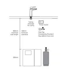
Determine unit location
Plan the installation. Dispenser tube lengths,
benchtop and cupboard restraints and drainage
requirements must be considered when
determining location. Use template enclosed
for drilling and cut-out details. Refer also to
appliance installation requirements supplied
with Drinking Water System.
Drainage location
Careful design and installation is essential
to provide satisfactory drainage performance
and to prevent later blockages. The Billi Font
is designed to be able to be connected to
a dishwasher nipple using either flexile or
rigid tubing or copper tubing. Where a
horizontal run is needed, we recommend
20mm or 25mm copper tubing be used.
An adapter bush is supplied for use where
a standard 40mm trap and drain is installed.
IMPORTANT
If drain is to be connected to a dishwasher
nipple, ensure hole through nipple is drilled
to at least ø12.7mm (1/2”) and de-burred,
to allow adequate flow.
Drain must be installed with a continual
fall along the entire length of the tube.
The Billi Fixture is to be installed by
a licensed tradesperson in accordance
with as 3500.4 Or AS/NZ 3500.4.2
And in compliance with applicable
state regulatory requirements.
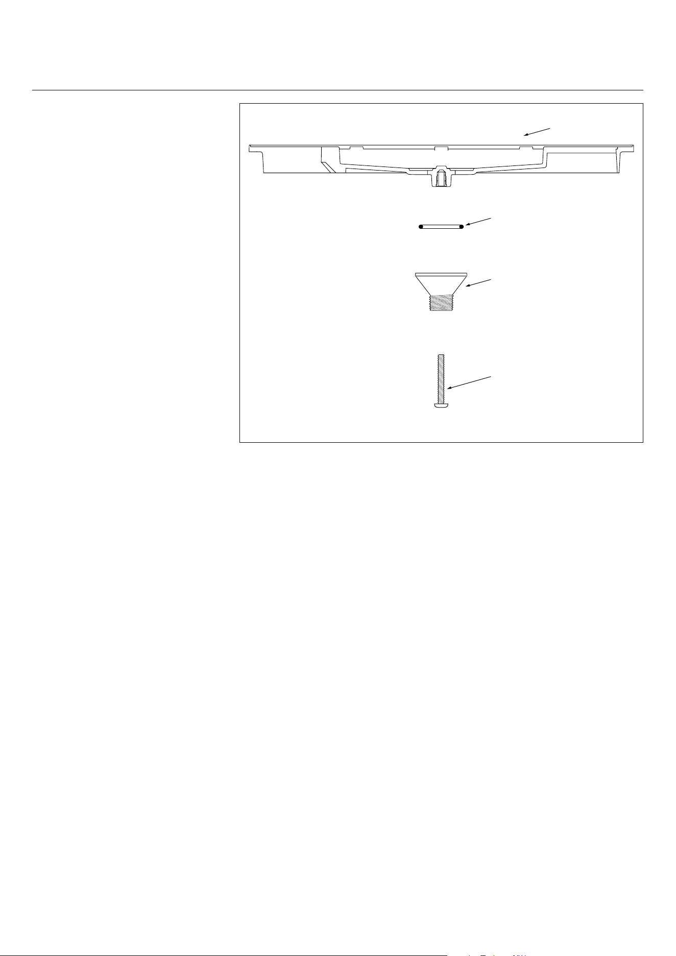
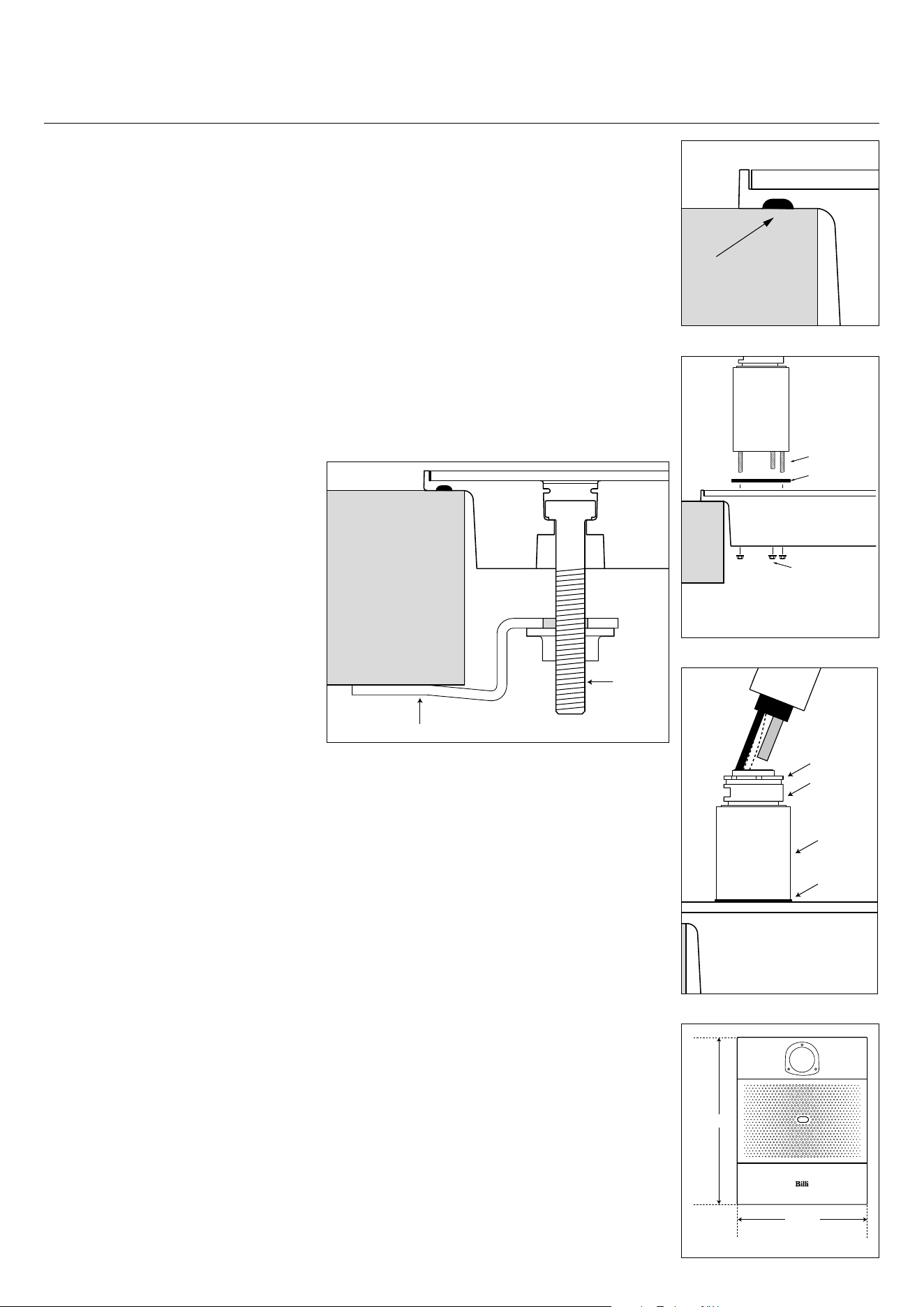
Diagram 1
Font tray
O-ring
Drain adapter
M5 x 45 screw
3
Installation procedure.
Proud Mount
1. Marking and Drilling Holes
a. Cut the template out and place template
in appropriate position. Check underneath
benchtop for possible obstructions such
as dividers, existing plumbing, etc. Trace
round the template and drill a pilot hole
for the jigsaw, using the jigsaw follow the
line in which was traced onto the bench
– see diagram 7 on next page.
2. Fitting Drain Adapter
a. Fit O-ring to Drain adapter.
b. Fit Drain adapter to tray. Tighten M5
screw, Note: Do NOT over-tighten
the screw.
c. Drain tube and elbow fitting are to
face dispenser mount hole – refer to
diagram 1 on previous page.
3. Fitting Billi Font to Benchtop
a. Ensure silicone bead is installed around
the edge of the cut out – ref to diagram 2.
b. Lower the Font tray into the cut out and
insert 4 x M6 bolts, one in each corner.
c. Fit the clips and M6 Flange nuts to all 4
bolts – refer to Diagram 3.
e. Tighten nuts until rim sits flat on
benchtop. Do NOT over-tighten nuts.
4. Fit front and rear cover plates
a. Remove protective film from cover
plate set.
b. Remove gasket cover and insert cover
into font tray.
c. Ensure holes in rear cover plate align with
the holes in the font tray.
d. Apply pressure around edge of plate(s)
to ensure proper gasket seal.
5. Fitting Dispenser Riser – refer to diagram 4.
a. Screw 3 x M4 studs into the rear
of the riser.
b. Fit the Gasket over the studs.
c. Place the riser through the cover plate
and into position on the font.
d. Fit and tighten 3 x M4 Flange nuts
to the underside of the Font tray.
6. Fitting Dispenser Head Assembly
(refer to diagram 5)
a. Feed dispenser tubing and loom
through centre hole in riser
in the following order:
i. Dispenser power cord
ii. Grey vent silicone tube. Feed tube until
reducing join passes through Mount
riser assembly – see diagram 5.
iii. Red and blue silicone tubing. Check
tubing is not kinked or twisted.
b. Turn dispenser head to 60° from the
straight ahead position of mount base.
Slide head assembly onto base assembly
whilst gently pulling tubing downwards
from underneath. Dispenser mounting
lugs will pass over and slide down the 3
grooves on the swivel bearing.
c. Once fully down, turn dispenser head to
straight ahead position. Fit M4 x 10mm
retaining screw rear threaded hole and
tighten with
Allen Key supplied.
7. Connect Tubing to Underbench Module
a. Connect dispenser tubing to underbench
module as per installation instructions
supplied with your unit.
8. Connect Drainage
a. Connect drainage tubing with reference
to Drainage Requirement instructions
on previous page. Drainage tube must
be installed with a continual fall along
the entire length of the tube and must be
adequately clipped and supported.
Diagram 3
Bench Font tray
Clip
M6
Bolt
Seal between
Font and Benchtop
Diagram 2
Bench Font tray
Diagram 4
Riser
Font trayBench
3 x M4 studs
Gasket
3 x M4 nuts
Diagram 5
Font tray
Gasket
Mount riser
Swivel
bearing
Nut
291mm
191mm
Diagram 6
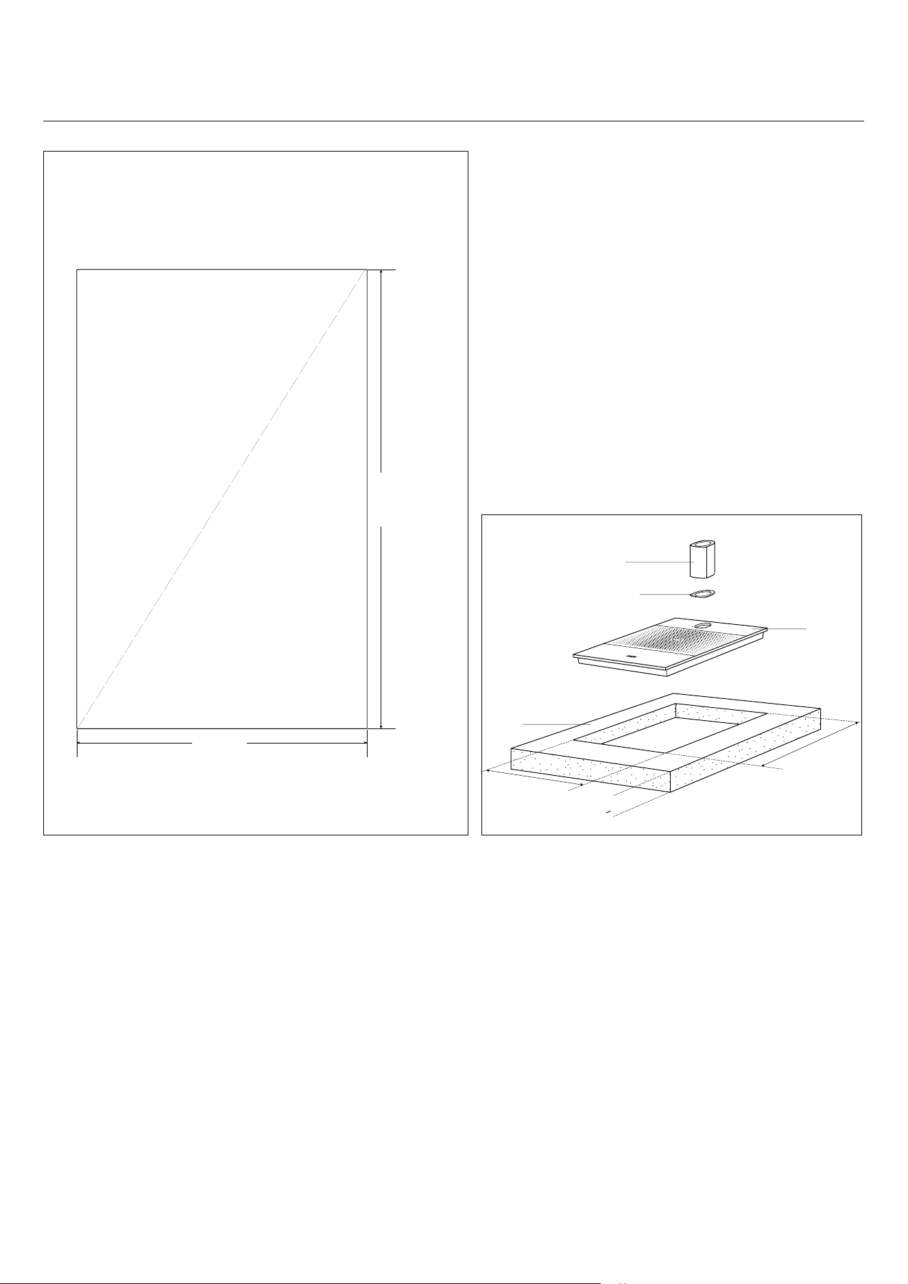
4
Hole Cut-Out Dimensions
– See Template for actual size,
Before using check dimensions
are accurate.
Installation procedure.
Proud Mount
272mm
SIDE
172mm
FRONT
Not to scale
172.0mm
272.0mm
>
25mm
Riser
D Washer
Bench
Font
Diagram 7bDiagram 7a
Bench
TOP VIEW
EXPLODED DIAGRAM
5
Installation procedure.
Flush Mount
1. Marking and Drilling Holes
a. Cut the template out and place template
in appropriate position. Check underneath
benchtop for possible obstructions such
as dividers, existing plumbing, etc. As a
guide only use the template and drill a
pilot hole for the jigsaw, using the jigsaw
follow the line in which was traced onto
the bench. Use appropriate router bits to
give R5.0 edges – see page 8.
2. Apply thick coat of moisture primer to all
cut surfaces
3. Fitting Drain Adapter
a. Fit O-ring to Drain adapter.
b. Fit Drain adapter to tray. Tighten M5
screw, Note: Do NOT over-tighten
the screw.
c. Drain tube and elbow fitting are to
face dispenser mount hole –refer to
diagram 1 on page 2.
4. Fitting Billi Font to Benchtop
a. Ensure silicone bead is installed around
the edge of the cut out – ref to diagram 2.
b. Lower the Font tray into the cut out and
insert 4 x M6 bolts, one in each corner.
c. Fit the clips and M6 Flange nuts to all
4 bolts – refer to diagram 3.
e. Tighten nuts until rim sits flat on
benchtop. Do NOT over-tighten nuts.
5. Fit front and rear cover plates
a. Remove protective film from cover
plate set.
b. Remove gasket cover and insert cover
into font tray.
c. Ensure holes in rear cover plate align with
the holes in the font tray.
d. Apply pressure around edge of plates
to ensure proper gasket seal.
6. Fitting Dispenser Riser
(refer to diagram 4)
a. Screw 3 x M4 studs into the rear
of the riser.
b. Fit the Gasket over the studs.
c. Place the riser through the cover plate
and into position on the font.
d. Fit and tighten 3 x M4 Flange nuts
to the underside of the Font tray.
7. Fitting Dispenser Head Assembly
(refer to diagram 5)
a. Feed dispenser tubing and loom
through centre hole in riser
in the following order:
i. Dispenser power cord
ii. Grey vent silicone tube. Feed tube until
reducing join passes through Mount
riser assembly – see Diagram 3.
iii. Red and blue silicone tubing. Check
tubing is not kinked or twisted.
b. Turn dispenser head to 60° from the
straight ahead position of mount base.
Slide head assembly onto base assembly
whilst gently pulling tubing downwards
from underneath. Dispenser mounting
lugs will pass over and slide down the 3
grooves on the swivel bearing.
c. Once fully down, turn dispenser head to
straight ahead position. Fit M4 x 10mm
retaining screw rear threaded hole and
tighten with
Allen Key supplied.
8. Connect Tubing to Underbench Module
a. Connect dispenser tubing to underbench
module as per installation instructions
supplied with your unit.
9. Connect Drainage
a. Connect drainage tubing with reference
to Drainage Requirement instructions
on previous page. Drainage tube must
be installed with a continual fall along
the entire length of the tube and must be
adequately clipped and supported.
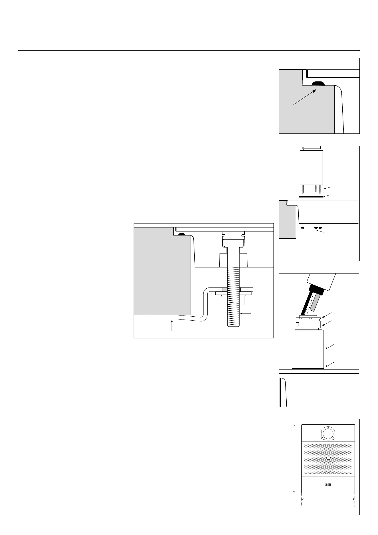
Seal between
Font and Benchtop
Diagram 2
Bench Font tray
Diagram 5
Font tray
Gasket
Mount riser
Swivel
bearing
Nut
Diagram 3
Bench Font tray
Clip
M6
Bolt
291mm
191mm
Diagram 6
Diagram 4
Riser
Font trayBench
3 x M4 studs
Gasket
3 x M4 nuts
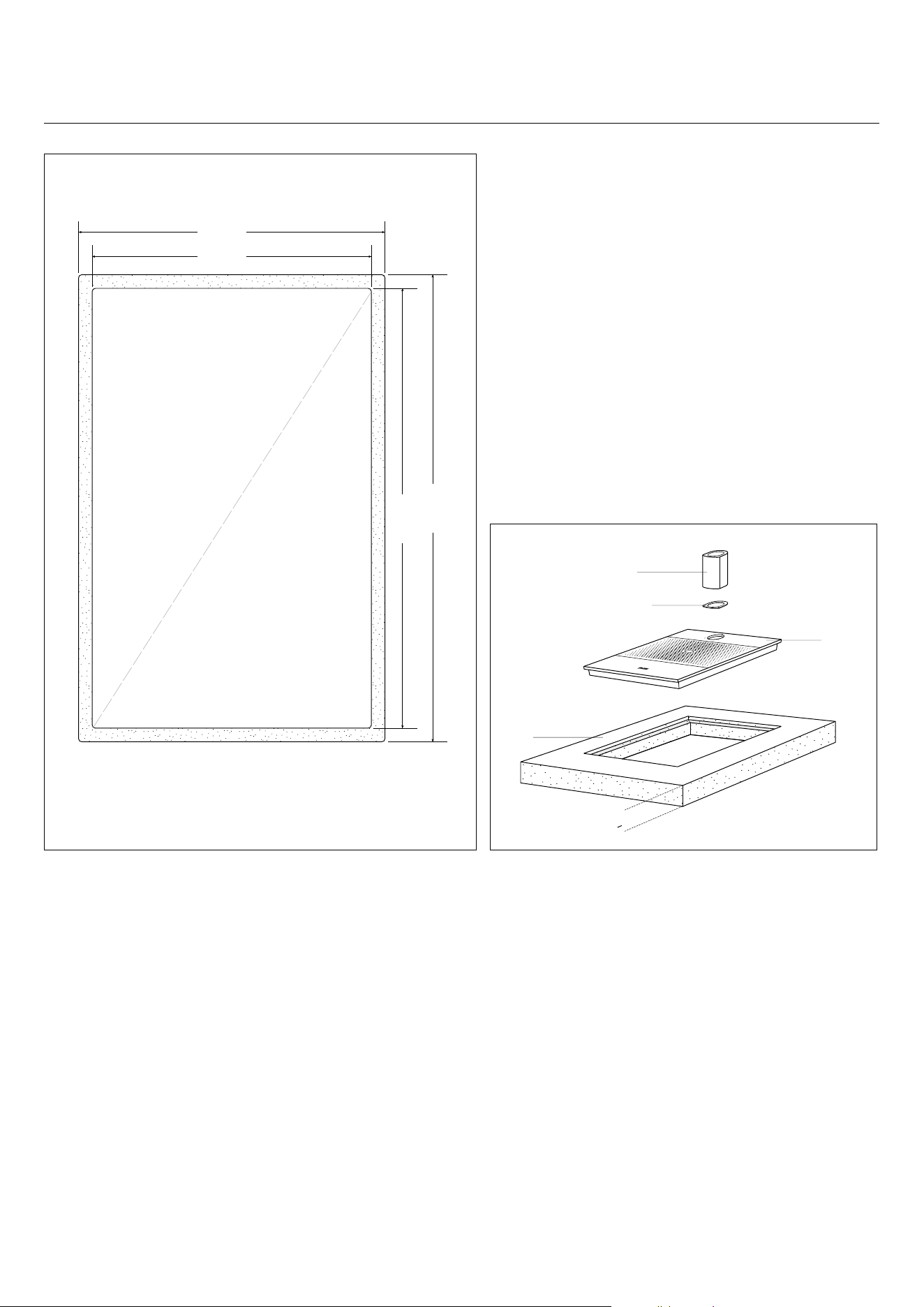
6
Installation procedure.
Flush Mount
Hole Cut-Out Dimensions
– See Template for actual size,
Before using check dimensions
are accurate.
191.0mm
TOP VIEW
174.0mm
291.0mm
274.0mm
FRONT
SIDE
Diagram 7a
Bench
Font cut out:
174mm (wide) x 274mm (long)
Rebate cut: 5.5mm (deep)
191mm (wide) x 291mm (long)
Corner Radius: 5mm
Tolerance: +/- 0.2mm
8.5mm
8.5mm
8.5mm
8.5mm
Not to scale
>
25mm
Riser
D Washer
Bench
Font
Diagram 7b
EXPLODED DIAGRAM


Billi Australi
a Pty Ltd
42 Luckno
w Cr
escent, Thomastown
Victoria 3074 Australia
Telephone +61 3 9469 0400
Facsimile +61 3 9469 0499
www.billi.com.au
Designed and
manufactured i
n Australia.
As Billi Australia Pty Ltd has a policy of
continual improvement, all details are
subject to change without notice. All
goods are sold subject to our published
terms and conditions. Billi is a registered
trademark. 0618
If any problems or difficulties arise contact Billi Australia Pty Ltd: Phone 1800 812 321 (Free call).
To validate your warranty refer to the warranty card or validate online at www.billi.com.au
For information on our filtration and service contracts please contact Billi Customer Service on
1800 812 321 or [email protected].