To reduce the risk of fire, electric shock or injury to persons using this freezer, read all
instructions and follow basic safety precautions before using the unit, including the following:
Do not modify the plug provided with the freezer. If it will not fit the outlet,
have a proper outlet installed by a qualified electrician.
Do not position equipment so it is difficult to disconnect from the power supply.
freezer must be at least 6” away from any wall or object on any side.
While under warranty, do not attempt to repair or replace any part of the
freezer for servicing without first contacting the So-Low Service Department.
SAVE THESE INSTRUCTIONS
♦
● MEANING OF ILLUSTRATED SYMBOLS…………………………………...
● STARTING INSTRUCTIONS…………………………………………………..
♦
● PRE-INSTALLATION INFORMATION………………………………………...
♦
● CLEANING PROCEDURE……………………………………………………..
● DEFROSTING PROCEDURE………………………………………………….
♦
● PART NUMBERS…………………………………………….………….………
4
♦
● TEMPERATURE CONTROL….………………………………………………..
6
● CONTROL CALIBRATION……………………………………………………..
7
♦
♦
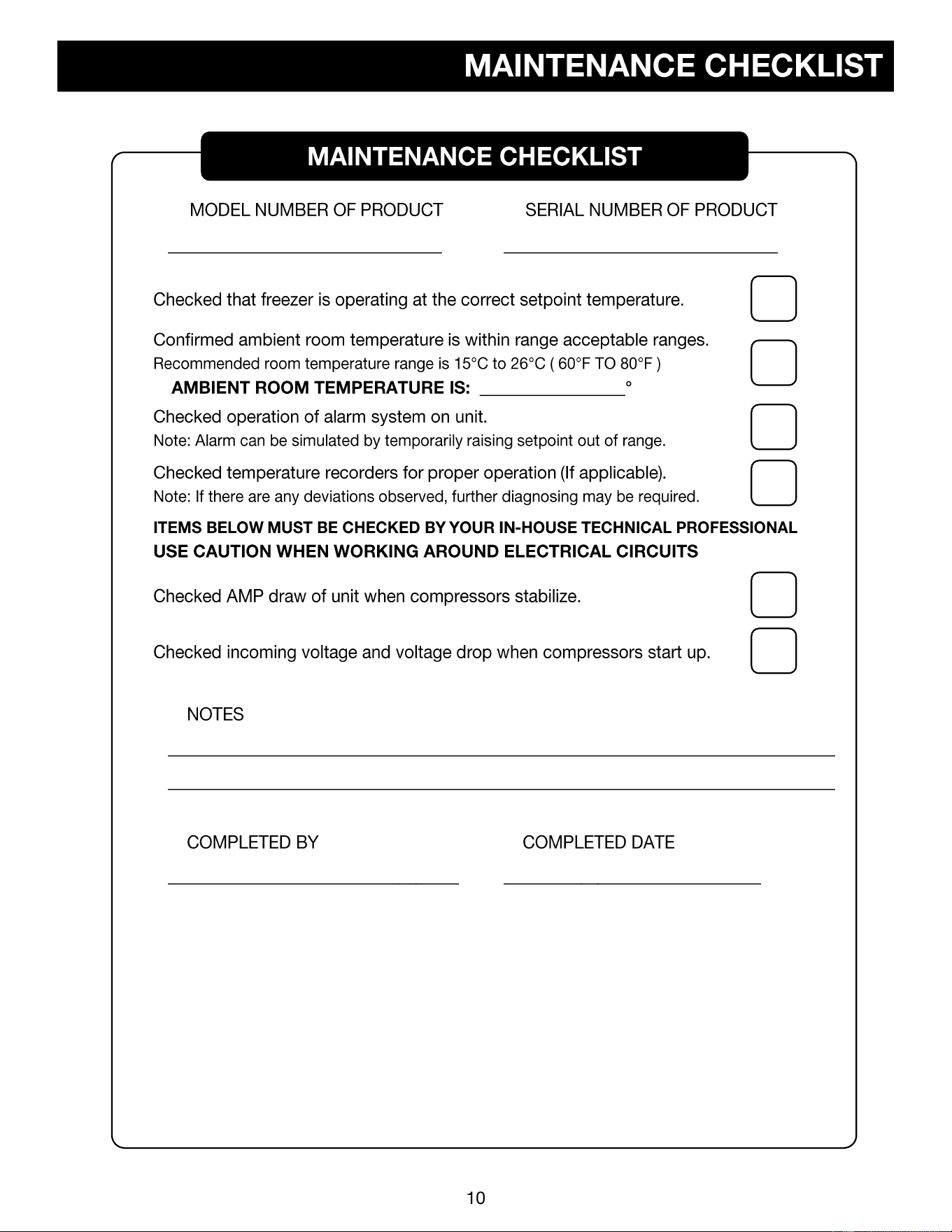
♦ MAINTENANCE CHECKLIST
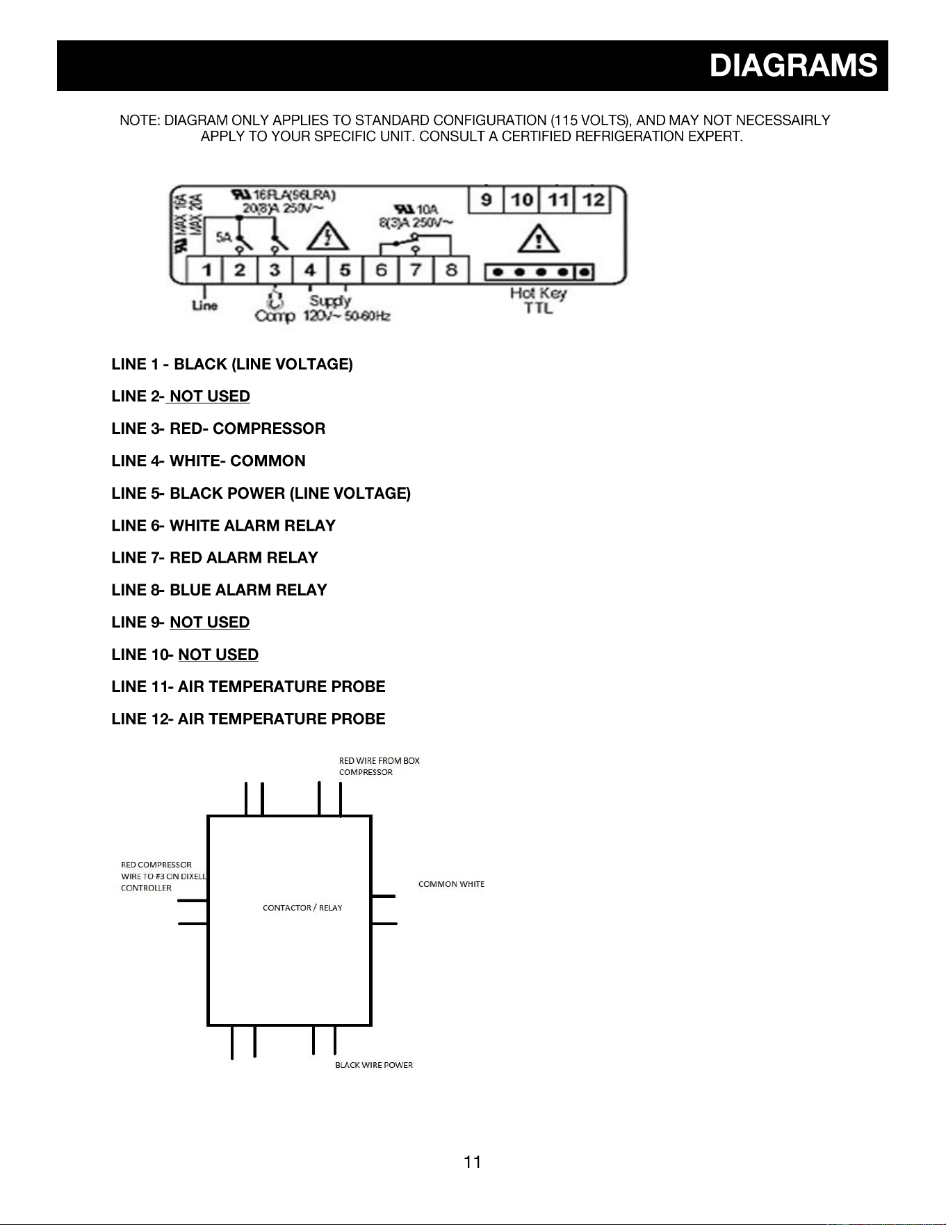
♦ DIAGRAMS
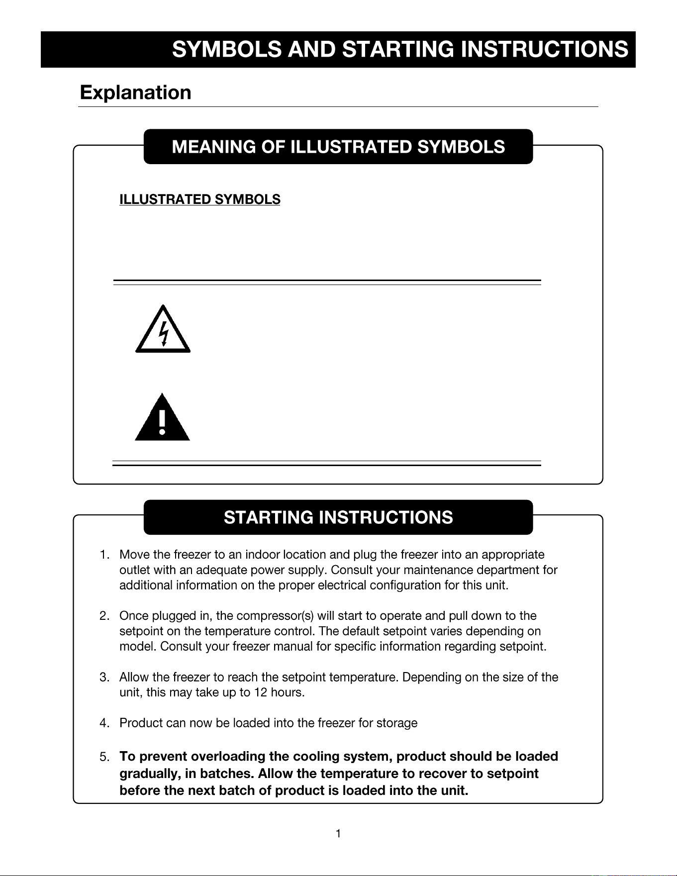
Various symbols are used in this safety manual in order to use the unit without
danger of injury and damage of the unit. Be sure that you understand the
warnings and cautions in this manual before operating the unit.
CAUTION
BLACK WITH YELLOW BACKGROUND
LIGHTNING BOLT
CAUTION, RISK OF ELECTRICAL SHOCK
WARNING
BLACK WITH YELLOW BACKGROUND
EXCLAMATION POINT
CAUTION, REFER TO ACCOMPANYING DOCUMENTS
WARNING
DURING OPERATION THIS UNIT MUST REMAIN IN UPRIGHT
POSITION. DURING TRANSPORATION UNIT MUST NOT BE
TIPPED MORE THAN 45° FROM UPRIGHT POSITION.
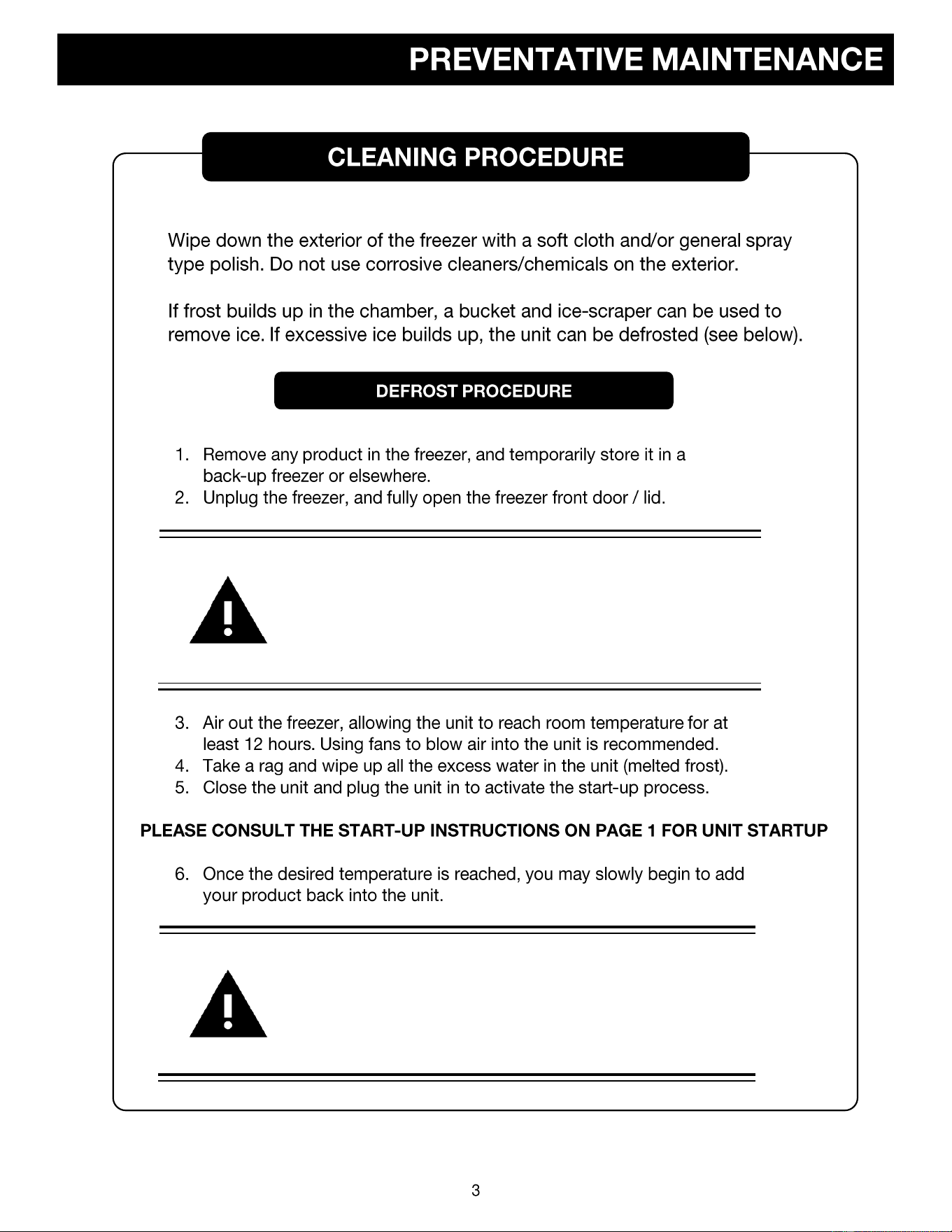
CAUTION
UNPLUG UNIT AND SWITCH OFF ELECTRICAL BREAKER
BEFORE ANY TECHNICAL SERVICE IS PERFORMED.
CAUTION
COVERS ON BACK / SIDE OF FREEZER MAY ONLY BE
REMOVED BY AUTHORIZED PERSONNEL. FAILURE TO
RE-INSTALL COVER COULD RESULT IN HAZARD.
CAUTION
ONLY PLUG THIS UNIT INTO THE PROPER OUTLET. DO
NOT ATTEMPT TO MODIFY PLUG IN ANY WAY. IMPROPER
USE OF THE ELECTRICAL PLUG WILL VOID WARRANTY.
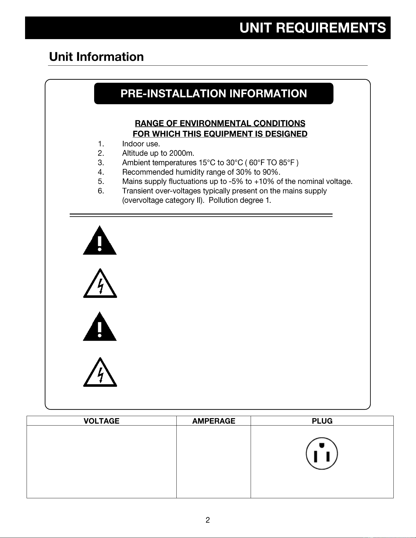
115 VOLTS
60 HERTZ
1 PHASE
(SUPPLY VOLTAGE SHOULD NOT VARY MORE
THAN 5% FROM SERIAL PLATE RATINGS.)
15 AMP
DEDICATED LINE
NEMA 5-15
ATTENTION
FOR UPRIGHT UNITS, IT IS IMPORTANT TO PROTECT THE
CONTROL FROM DRIPPING WATER. PLACE A CLOTH OR
TOWEL ON THE LEADING EDGE OF THE COOLING
CHAMBER ABOVE THE CONTROL TO DEFLECT / ABSORB
WATER THAT COULD DRAIN ONTO THE CONTROL.
ATTENTION
IT IS RECOMMENDED TO SLOWLY RE-ADD YOUR
PRODUCT INTO THE FREEZER TO PREVENT AN
EXTREME LOAD ON THE COMPRESSORS, WHICH
COULD SHORTEN FREEZER LIFE EXPECTANCY.
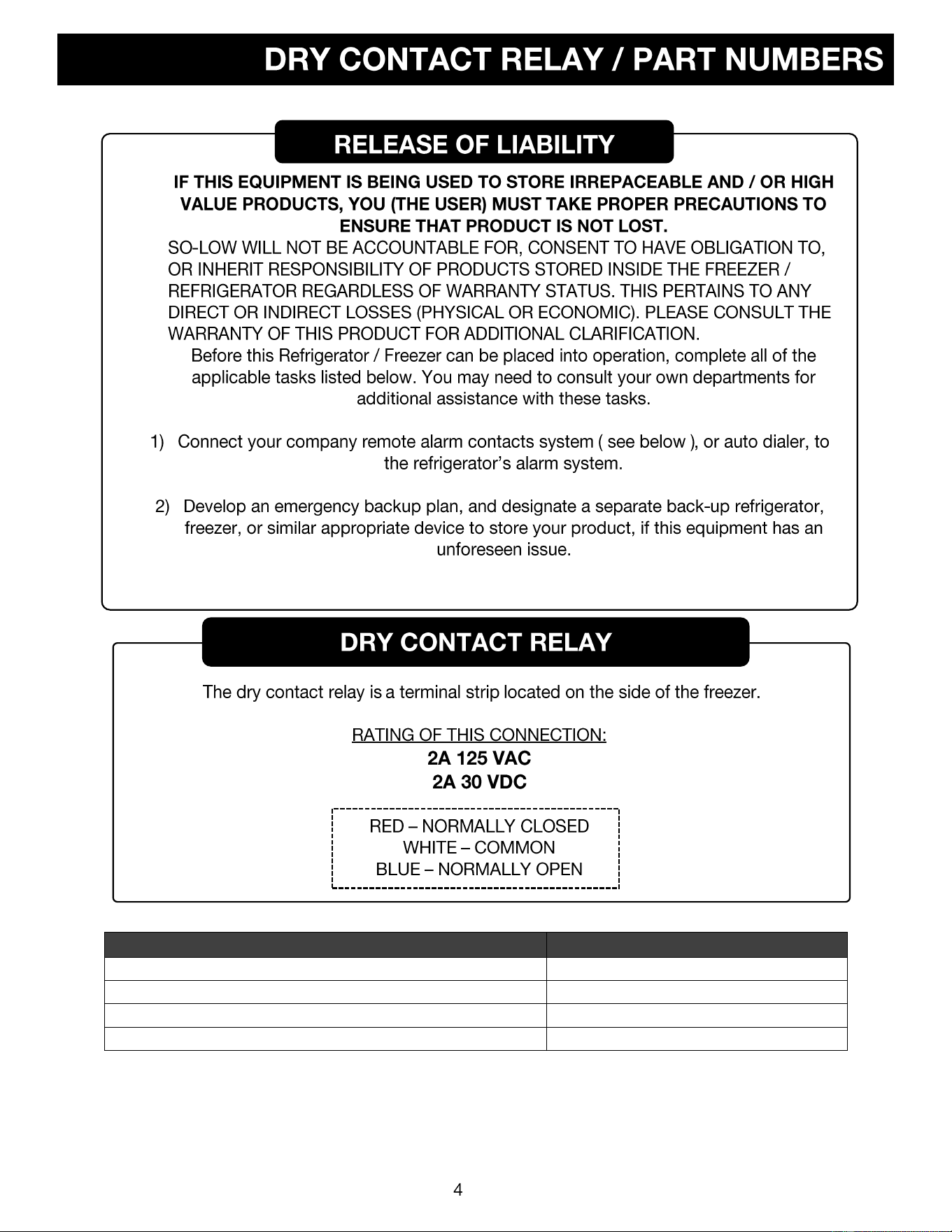
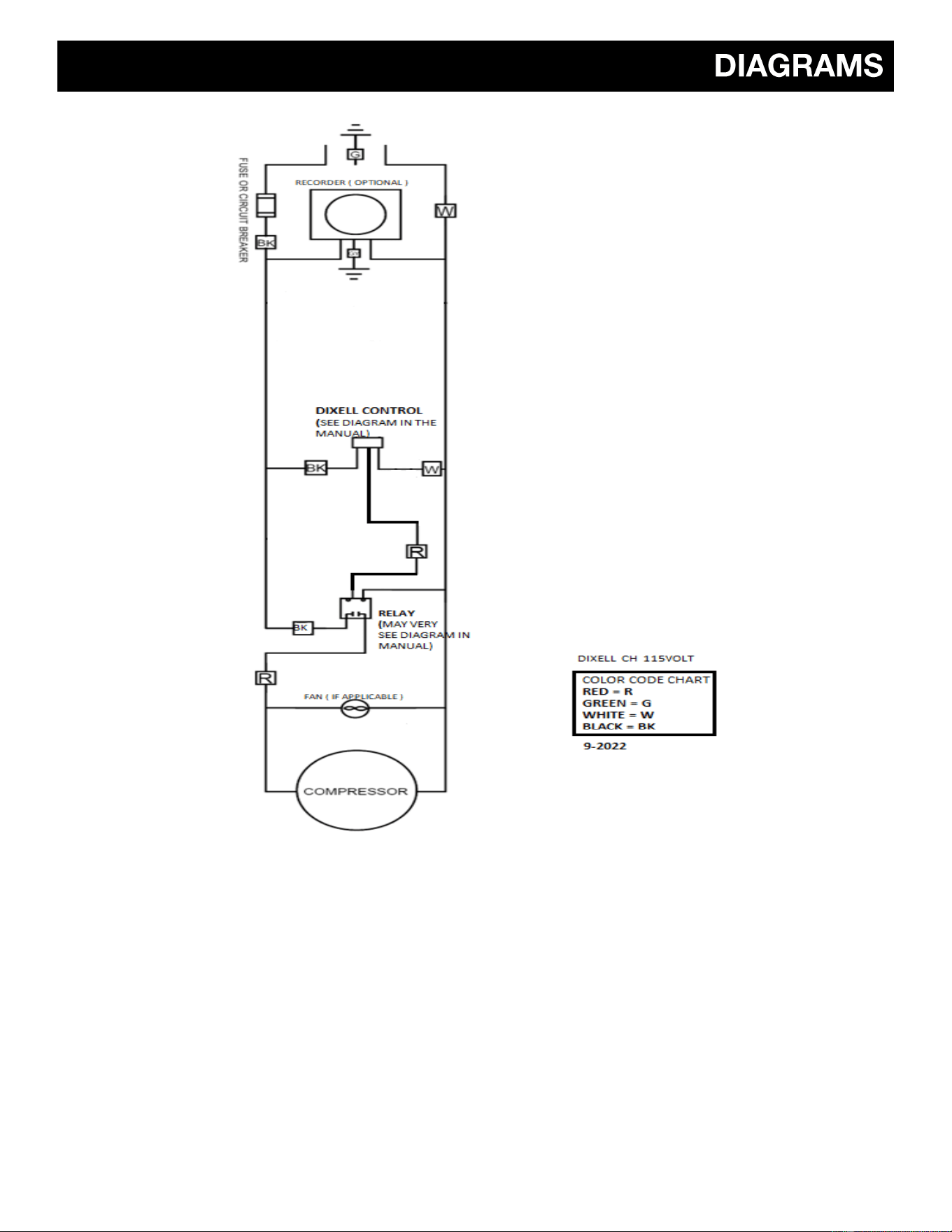
TEMPERATURE CONTROL PARTS
PART #
DIXELL CONTROL
XR60-CH
TEMPERATURE PROBE FOR DIXELL CONTROL
DH-PROBE
RELAY
DH-RELAY
COMPRESSOR FAN
CH-FAN
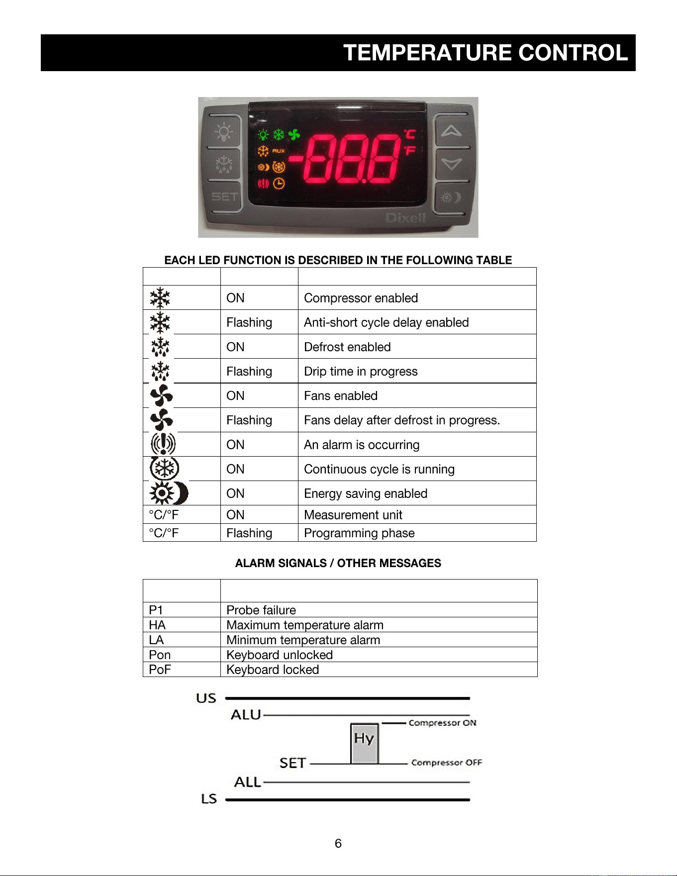
LED
MODE
FUNCTION
MESSAGE
CAUSE
•
•
•
•
•
•
•
•
•
o
o
•
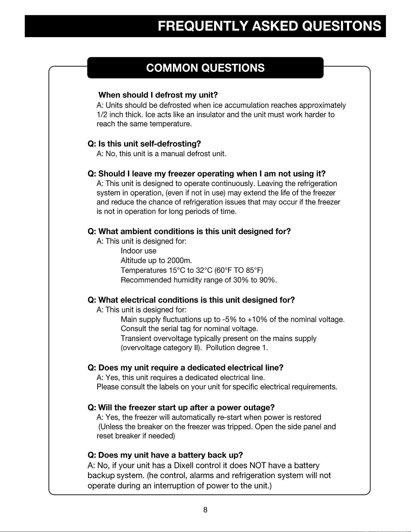
Q:
•
•
•
•
•
•
◆ ◆
◆
◆
◆ ◆
TEMPERATURE TO RESISTANCE
CHART NTC THERMISTOR
Temp C Temp F Resistance Ohms
- 50 - 58 329.5
- 45 - 50 247.7
- 40 - 40 188.5
- 35 - 31 144.1
- 30 - 22 111.3
- 25 - 12.5 86.43
- 20 - 4 67.77
- 15 5 53.41
- 10 14 42.47
- 5 23 33.9
0 32 27.28
5 41 22.05
10 50 17.96
15 59 14.69
20 68 12.09
25 77 10.00
30 86 8.313
35 95 6.94
40 104 5.827
45 13 4.911
50 122 4.160
55 131 3.536
60 140 3.020
65 149 2.588
70 158 2.228
75 167 1.924
80 176 1.668
85 185 1.451
90 194 1.266
95 203 1.108
100 212 0.9731
105 221 0.8572
110 230 0.7576
All Resistance is k or (x1000)