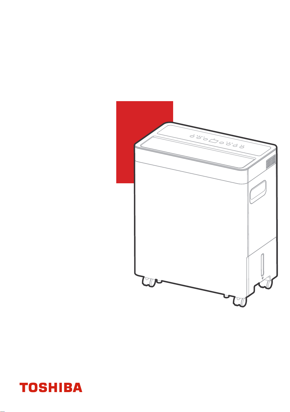
使用說明書
重要提示:
在使用本產品前,請仔細閱讀本手冊,
並妥善保管以備日後參考。
設計和規格如有更改,恕不另行通知。
二合一空氣淨化抽濕機
RAD-DA11HK-1
RAD-DA13HK

頁面2
目錄
部件識別
了解產品................................................................................................10
安全注意事項.........................................................................................3
定位裝置
使用產品時
控制面板功能
了解功能................................................................................................13
水桶排水 (類型 1)
水管排水(連續) (類型 2)
傾倒積水................................................................................................16
清潔格柵和外殼
清潔水桶
清潔空氣過濾器
長期不用機器時
保養與維修............................................................................................18
故障排除................................................................................................20
頁面3
安全注意事項
安全注意事項
符號說明
閲讀《操作和安裝前安全注意事項》非常重要。由於忽略本説明而導致安裝不當,可能導致嚴重
損壞或傷害。
潛在損害或傷害的嚴重性分為警吿或注意。
在使用/調試抽濕機前,請仔細閲讀這些操作説明,並妥善儲存在裝置安裝現場附近以備日後使用!
警告
此警示詞表示危險程度較高,如果不避免,可能導致嚴重傷害或死亡。
此警示詞表示風險程度較低的危險,如果不避免,則可能導致輕微或
中度傷害。
注意
• 不要超過電源插座或連接裝置的額定值。
• 請勿透過開啟或切斷電源來操作或停止本裝置。
• 請勿損壞電源線,或使用非指定的電源線。
• 請勿更改電源線長度或與其他電器共用插座。
• 不要用濕手插拔插頭。
• 抽濕機不得安裝在可能接觸可燃氣體的位置。
• 抽濕機不要靠近熱源。
• 如果發出奇怪的聲音、氣味或煙霧,請斷開電源。
• 絕不要試圖自行拆開或修理抽濕機。
• 清潔抽濕機前關閉電源並拔掉插頭。
• 不要在易燃氣體或可燃物如汽油、苯、稀釋劑等附近使用抽濕機。
• 不要飲用或使用從抽濕機中排出的水。
• 抽濕機工作時請勿取出水桶。
• 抽濕機上不得放置可能濺水的物品。
• 抽濕機宜放置在牢固的水平地板上。
• 勿用布或毛巾覆蓋進排氣口。
• 房間裡若有以下人員應小心使用抽濕機:嬰兒、兒童、老人和對濕度不敏感的人。
• 不要在處理化學品的區域使用抽濕機。
• 絕不要用手指或其他異物插入抽濕機格柵或開口。特別注意對孩子們警吿上述危險。
• 重物不要放在電源線上,小心不要擠壓電源線。
• 不要攀爬或坐在抽濕機上。
• 始終安全插入空氣過濾器。每兩週清潔一次空氣過濾器。
• 如果水進入抽濕機,請關閉裝置並斷開電源,聯絡合格的維修技術員。
• 勿在抽濕機頂部放置花瓶或其他裝水容器。
• 不要使用加長電源線。
警吿
• 不低於 8 歲的兒童,身體、感官或精神能力下降或缺乏經驗常識的人員,如果給予他們關於
安全使用本抽濕機的監督或指導,並了解相關風險,可以使用本裝置。兒童不得玩弄抽濕機。
不得由兒童在無監督情況下執行其清潔和用戶維護。(適用於歐洲國家)
• 本抽濕機對於身體、感官或精神能力下降或缺乏經驗常識的人員(包括兒童)不適用,除非
給予他們關於安全使用本抽濕機的監督或指導。兒童應受監督,確保他們不玩弄抽濕機。
(適用於除歐洲國家以外的其他國家或地區)
• 如果電源線損壞,必須由製造商、其服務代理或類似的合格人員更換,以避免危險。
• 在執行清潔或其他維護作業前,必須斷開抽濕機的電源。
• 抽濕機不得安裝在可能接觸可燃氣體的位置。
• 如果可燃氣體在抽濕機週圍積聚,可能引起火災。
• 如果抽濕機在使用過程中被撞翻,請立即關閉裝置,並立即拔下電源線。目視檢查抽濕機確保
沒有損壞。如果懷疑抽濕機已損壞,請聯絡技術員或客戶服務尋求幫助。
• 雷雨天氣必須切斷電源,以免雷電損壞抽濕機。
• 不要在地毯下面拉電線。不要用地毯、轉輪或類似的覆蓋物覆蓋電線。不要在傢俱或抽濕機
下面佈線。電線宜遠離通行區域和不會被絆倒的地方。
• 勿對抽濕機使用損壞的電線或插頭。廢棄抽濕機或返回給授權的服務機構進行檢修。
• 為了減少火災或觸電的危險,勿將此風扇與任何固態速度控制裝置配合使用。
• 應依照國家接線規定安裝抽濕機。
• 請聯絡授權的維修技術員維修或保養本抽濕機。本產品不用時請關閉電源。
注意
• 製造商銘牌位於裝置後面板上,含有本裝置的特定電氣參數和其他技術數據。
• 確保裝置正確接地。為了儘量減少震動和火災風險,重點必須正確接地。電源線配有三叉接
地插頭,以防產生電擊危險。
• 使用抽濕機必須連接接地良好的牆壁插座。如果待用牆壁插座未充分接地或沒有延時保險絲
或斷路器保護(參閲銘牌了解電氣數據),請安排合格電工安裝適當的插座。
• 不要在潮濕的房間如浴室或洗衣間操作抽濕機。抽濕機電路板(PCB)設計有保險絲提供過
流保護。
注意
• 含氟温室氣體置於密封裝置中。有關含氟温室氣體的類型、數量和二氧化碳當量(某些機型
專有)的具體資訊,請參閲抽濕機本身的相關標籤。
• 本裝置的安裝、服務、維護和檢修必須由認證技術員執行。
• 產品拆卸和回收必須由認證技術員執行。
氟化氣體有關提示(採用 R290 製冷劑的抽濕機不適用)
頁面4
安全注意事項
• 室內不得使用可重複使用的機械接頭和喇叭形接頭。
• 為了安全起見,裝置已配備檢漏系統。為了有效檢漏,裝置必須在安裝後隨時通電,檢修時除
外。
• 不要使用加速除霜過程或清潔方法,製造商推介的方法除外。
• 電器儲存的房間內應沒有持續工作火源(例如明火、工作中的燃氣裝置或工作中的電加熱器)。
• 不得出現扎破或燒傷事故。
(產品如果含有 R32 製冷劑,
僅限於符合 IEC 60335-2-40:2022 標準)
• 注意製冷劑可能不含異味。
警吿
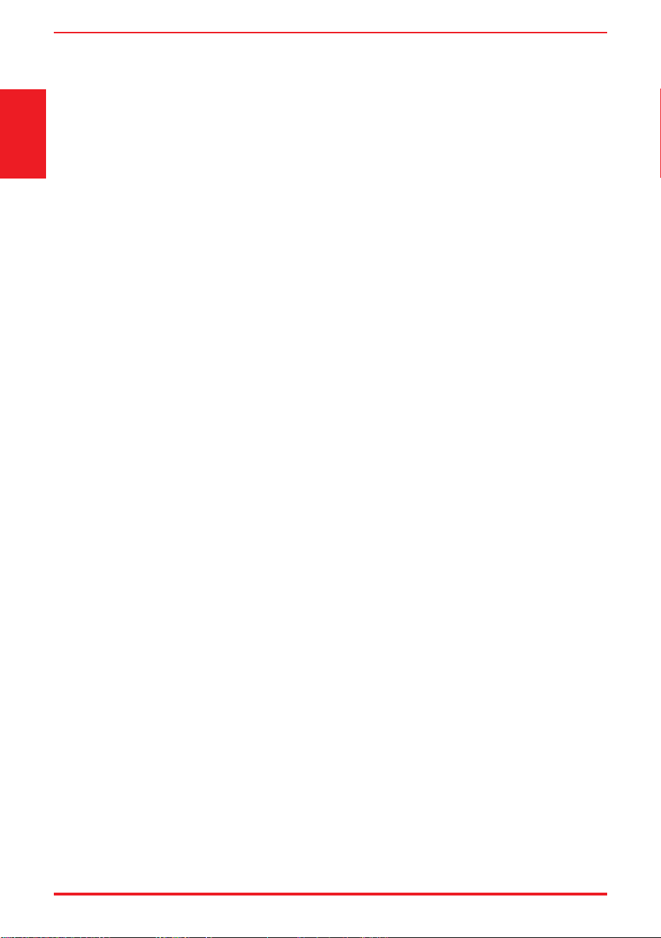
警吿:易燃物料
室內機或室外機上顯示符號的説明
頁面5
安全注意事項
注意
注意
注意
警吿
此符號表示本電器使用易燃冷媒。如果製冷劑泄漏並接觸
外部火源,則存在著火風險。
此符號表示應仔細閲讀操作手冊。
此符號表示諸如操作手冊或安裝手冊之類的可用資訊。
此符號表示維修人員應參照安裝手冊處理此裝置。
頁面6
安全注意事項
1. 安裝(空間)
-管道工件的安裝應儘量簡單易行。
-保護管道工件不受物理損壞。
-製冷劑管道應遵守關於氣體的國家法規。
-機械連接應觸手可及,便於維護。
-如果需要機械通風,通風開口應保持通暢。
-使用產品時應根據國家規定妥善處理。
2. 檢修
-任何參與或中斷制冷劑迴路工作的人員都應持有行業認可的評估機構頒發的當前有效證書,
此類 機構授權其根據行業認可的評估規範安全處理製冷劑的資質。
3. 如果維護和修理作業需要其他熟練人員協助,應在具備易燃製冷劑資質的人員監督下執行。
4. 尤其注意不得讓(油、水等)異物進入管道。此外,在儲存管道時,透過擠壓、貼膠帶等方法
牢牢密封開口。
5. 所有影響安全設施的作業流程只能由具備資質的人員執行。
6.沒有最少房間使用面積要求。
7. 電器應當妥善儲存,以防機械損壞。
8. 對於管道產品,連接到電器的管道不得包含潛在火源;
9. 當透過空氣管道系統連接到一個或多個房間時,送風和迴風應直接通往這些空間。
假天花板等開放區域不得用作迴風管道;
10. 避免製冷管道過度振動或脈動
11. 無論裝置在安裝後處於靜止狀態和運行狀態,或在至少這些靜止或運行條件的壓力下,均應使
用製冷劑靈敏度為 5 克/年或更靈敏的檢測裝置測試接頭。裝置的室內側不得使用可拆卸接頭
(可用釺焊、電焊接頭)。
12. 如果使用易燃製冷劑,裝置安裝空間的要求和/或通風要求的決定依據是
-電器中使用的電量(M)、
-安裝位置、
-電器的通風類型或電器類型。
13. 只能依照製造商的建議執行檢修。
14. 使用易燃製冷劑時,請參閲以下安裝要求。
-- 應儘可能保護防護裝置、管道和配件,以免受到不利環境影響,例如減壓管中有積水和結
冰的危險,或積累污垢和殘渣;
-- 應採取預防措施避免製冷管道過度振動或脈動;
-- 製冷系統管道的設計和安裝應儘量減小液壓衝擊損壞系統的可能性;
-- 對於長管道的膨脹和收縮應當作出規定;
-- 管道中應正確放置電磁閥以避免液壓衝擊,且不得堵塞制冷液,除非提供充分泄壓;
-- 鋼制管道和部件應採用防鏽塗層作防腐保護後才能用於任何絕緣。
-- 現場製作的室內製冷管接頭應執行密封性測試。測試方法的靈敏度應為至少在 0.25 倍最大
允許壓力條件下制冷劑泄漏不得高於 5 克/年。不應檢測到泄漏;
-- 可能產生電弧或火花的電子器件,由於符合 22.116.1 之要點 b)、c)、d)或 f)而不被視
為火源,只能用電器製造商指定的零件代替。
如果用其他零件代替,萬一發生泄漏可能會導致製冷劑着火;
15. 通風不良區域
-- 如果裝有易燃製冷劑的電器安裝在通風不良區域,請確保它不會停止運行,從而對任何製
冷劑泄漏產生著火或爆炸的風險。
16. 工人資格
任何維護、服務和維修操作都要求工作人員具備資質。每一個影響安全措施的工作流程只
能由參加培訓並取得勝任資質的合格人員執行,並有證書備檔。此類流程的培訓由國家培
訓機構或製造商執行,此類經過認證的機構專門講授立法規定的相關國家資質標準。所有
培訓應遵循 IEC 60335-2-40:2022 版的附件 HH 的要求。
此類工作流程舉例如下:
· 中斷製冷迴路;
· 開啟密封元件;
· 開啟通風外殼。
檢修資訊
1. 檢查工作區
頁面7
安全注意事項
在開始使用含有易燃製冷劑的系統前,需要執行安全檢查,確保著火風險降至最低。對於製冷系
統的維修,在執行此類工作前,應遵守以下預防措施。
2. 工作流程
應在受控流程下開展工作,以儘量減少開展工作時存在易燃氣體或蒸汽的風險。
3. 一般工作區
向在現場工作的所有維修人員和其他人員説明即將開展的工作的性質。避免在密閉空間內工作。
4. 檢查是否有製冷劑
在工作前和工作期間,應使用適當的製冷劑探測器檢查工作區,確保技術人員意識到可能存在易
燃氣體。確保當前所用檢漏裝置適用於易燃製冷劑,即無火花、充分密封或本質上安全。
5. 配備滅火器
如果要對製冷裝置或任何相關部件執行任何動火作業,應準備好適當的滅火裝置。在充填區附近
配備乾粉滅火器或二氧化碳滅火器。
6. 無火源
任何人執行與製冷系統有關的工作,如涉及接觸任何管道工件,使用任何火源均不得導致著火
或爆炸的危險。所有可能的火源,包括吸煙,都應遠離安裝、修理、拆卸和處置地點,因為在
此期間製冷劑可能會釋放到週圍空間。在開始工作前,應檢查裝置週圍的區域,確保沒有易燃
或着火風險。應出示「嚴禁吸煙」標誌。
7. 通風區
在中斷系統或執行任何動火作業之前,確保工作區域處於開放狀態或通風良好。在開展工作期
間,應繼續保持通風良好。釋放的任何製冷劑都應透過通風安全擴散出去,並最好排到大氣中。
8. 檢查製冷裝置
在更換電子器件時,新器件應當合用,並且規格正確。應始終遵循製造商的維護和服務指南。
如有疑問,請諮詢製造商的技術部門尋求幫助。對使用可燃冷媒的裝置應進行以下檢查:
·製冷劑加注量與安裝含製冷劑裝置的房間大小一致;
·通風機械和出口工作良好,無阻塞;
·如果使用間接製冷迴路,應檢查二次迴路是否存在製冷劑;
·裝置上的標記一直清晰可見,糾正難以辨認的標記和標誌;
·製冷管或器件的安裝位置不能接觸可能腐蝕容納製冷劑的器件的任何物質,除非器件本身耐
腐蝕或由適當的防腐材料製成。
9. 檢查電氣裝置
電子器件的修理和維護應包括初始安全檢查和器件檢查流程。如果存在可能危及安全的故障,
則在電路得到令人滿意的處理之前,電源不得接入電路。如果無法立即糾正故障,但需要繼續
運行,應使用充分的臨時解決方案。應向裝置所有者報吿上述情況,以便告知各方。
初步安全檢查應包括:
·電容器放電:應以安全的方式進行,避免可能產生火花
·充填、回收或吹掃系統時,任何帶電的電子器件和電線均未裸露在外;
·地線連接良好。
10. 密封電子器件
密封的電子器件不得修理。
11. 佈線
檢查電纜,確保不會受到磨損、腐蝕、過壓、振動、銳邊或任何其他不利的環境影響。
檢查考慮因素還應包括老化或源於壓縮機或風扇的持續振動的影響。
頁面8
安全注意事項
12. 易燃製冷劑的檢測
在任何情況下均不得使用潛在火源來搜尋或檢測製冷劑泄漏。不得使用鹵化物檢漏燈(或任何
其他採用明火的探測器)。
以下檢漏方法對於製冷劑系統是可接受的。電子檢漏器可用於檢測製冷劑泄漏,但如果是易燃製
冷劑,靈敏度可能不夠,否則可能需要重新校準。(檢測裝置應在無製冷劑區域進行校準。)
確保探測器不是潛在火源,並且適用於所用製冷劑。檢漏裝置應設置在製冷劑著火下限(LFL)
百分比,並根據所用製冷劑校準,確認氣體百分比合適(最大 25%)。
檢漏液也適用於大多數製冷劑,但應避免使用含氯洗滌劑,因為氯可能與製冷劑反應並腐蝕銅管
工件。
提示:檢漏液實例如下:
- 氣泡法,
- 熒光劑法。
如果懷疑泄漏,則應清除/熄滅所有明火。
如果發現製冷劑泄漏需要釺焊,應從系統回收所有制冷劑,或(透過截止閥)在系統遠離泄漏的
部分隔離。請參閲以下説明取出製冷劑。
13. 製冷劑排出和迴路清空
因檢修或任何其他目的中斷製冷劑迴路時,應依照常規流程。但是對於易燃製冷劑,必須依照最
佳做法,因為必須考慮易燃性這個因素。請遵守以下流程:
·按照地方和國家法規安全取出製冷劑;
·排空;
·用惰性氣體吹掃管路(A2L 型可選);
·排空(A2L 型可選);
·使用火焰時斷開電路用惰性氣體連續沖掃或吹掃;
·斷開電路
充填的製冷劑應當回收到正確的回收鋼瓶中。製造商應指定可使用的惰性氣體。不得使用壓
縮空氣或氧氣淨化製冷劑系統。
提示:乾燥的氮氣視為一種惰性氣體。
應採用惰性氣體充入系統真空來淨化製冷劑迴路,並繼續充填直到達到工作壓力,然後排放到大
氣中,最後降壓到真空。應重複以上過程,直到系統內沒有製冷劑。此系統降低至大氣壓才能正
常工作。
確保真空泵的出口不靠近任何潛在火源,並且通風良好。
14. 充填流程
除常規充填流程外,還應遵循以下要求:
·確保在使用充填裝置時不同製冷劑不會發生污染。軟管或管路應儘可能短,以儘量減少其
中所含製冷劑量。
·鋼瓶應依照説明置於適當位置。
·向系統充填製冷劑前,確保製冷系統接地。
·充填完成時標記系統(如果尚未標記)。
·應特別注意製冷系統不得充填過滿。
重新充填系統前,應透過適當的氣體吹掃完成壓力測試。充填完成時,應對系統執行泄漏測試,
然後調試。離開現場前應執行跟蹤泄漏測試。
15. 廢棄
在執行此流程前,技術人員必須完全熟悉裝置及其所有細節。建議採用安全回收所有制冷劑
的良好做法。執行任務前,應對機油和製冷劑取樣,以便在重用回收的製冷劑前進行分析。
在任務開始前必須正常供電。
a)熟悉裝置及其操作
b)對系統進行電氣隔離
c)執行流程前確保:
·如果需要,可以使機械處理裝置來處理製冷劑鋼瓶;
·所有個人防護裝置均配備到位;
·回收過程隨時有合適的人員監督;
頁面9
安全注意事項
16. 標籤
裝置應貼上標籤,説明其已廢棄,並清空製冷劑。標籤應註明日期並簽名。對於含有易燃製冷
劑的電器,確保裝置上有標籤,説明裝置含有易燃製冷劑。
17. 回收
從系統中排出製冷劑時,無論是檢修還是廢棄,均要妥善處理,以便安全排出所有制冷劑。
轉移製冷劑到鋼瓶中時,確保僅使用適當的製冷劑回收鋼瓶。確保有足夠數量的鋼瓶容納全部
製冷劑。指定所有鋼瓶都用於回收製冷劑,並為其貼上標籤(即製冷劑回收專用鋼瓶)。鋼瓶
應配有減壓閥和相關的截止閥,且工況良好。清空回收鋼瓶,如果可能,冷卻後進行回收。
回收裝置應處於良好工況,並隨附裝置説明書,且適合回收易燃製冷劑。如有疑問,請諮詢製
造商。此外,請配備一套校準的稱重秤,並處於良好工況。軟管配備的斷開接頭應無泄漏且處
於良好工況。
根據當地法律,回收的製冷劑應採用合適的回收鋼瓶處理,並附上相關的廢物轉運説明。不要
在回收裝置中混合製冷劑,尤其不要在鋼瓶中混裝。
如果要拆卸壓縮機或排出壓縮機油,請確保先排空到可接受的液位,確保潤滑劑中不會殘留易
燃製冷劑。不得用明火或其他火源加熱壓縮機本體來加速上述過程。從系統排油應安全進行。
18. 裝置的運輸、標記和儲存
1. 遵守運輸法規運輸含有易燃製冷劑的裝置。
2. 遵守當地法規使用標誌標記裝置。
3. 遵守國家法規處置採用易燃製冷劑的裝置。
4. 裝置/家電的儲存應遵循製造商的説明儲存裝置。
5. 包裝(未售出)裝置的儲存
儲存包裝保護的構造應確保包裝內裝置的機械損壞不會導致製冷劑充填泄漏。
允許裝置一起存放的最大數量由當地法規決定
·回收裝置和鋼瓶符合適當的標準。
d) 如果可能,關閉製冷劑系統。
e) 如果無法完全排空,則製作歧管,以便從系統各部件排出製冷劑。
f) 回收前務必對鋼瓶秤重。
g) 啟動回收機並依説明操作。
h) 鋼瓶不要裝太滿(液體裝入量不超過 80%)。
i) 不要超過鋼瓶的最大工作壓力,臨時超壓也不允許。
j) 當鋼瓶正確充填並完成流程時,確保鋼瓶和裝置立即從現場移走,並關閉裝置上的所有隔離
閥。
k) 回收的製冷劑除非經過清潔和檢查,不得裝入另一個製冷系統。
頁面10
為確保公司產品的最佳性能,設備設計規範如有更改,恕不另行通知。
產品概述
了解產品
部件識別
設計通知
注
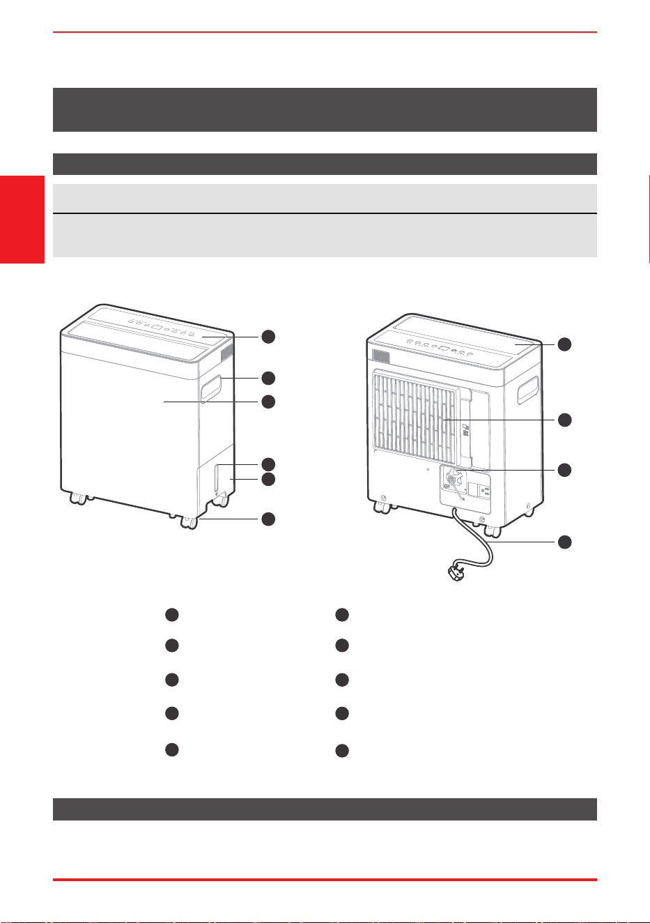
手冊中的所有插圖僅用於解釋含義。您的機器可能略有不同。具體情況以實際形狀為準。
透過控制面板可控制抽濕機。
前視圖
1
2
3
4
5
6
7
8
9
控制面板
把手(兩側)
液位窗
前面板
水桶
空氣過濾器(進氣格柵)
腳輪
連續排水軟管出口
出風格柵
10
電源線和插頭
了解產品
1
2
3
4
5
6
10
9
8
7
後視圖
頁面11
腳輪(裝置底部四點)
定位裝置
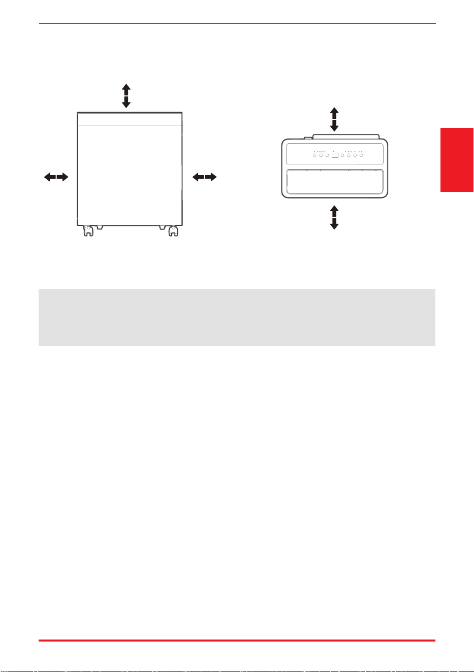
正面檢視 俯視
• 腳輪可自由移動。
• 不要強迫腳輪在地毯上移動,也不要在桶內有水的情況下移動裝置。(裝置可能會翻倒導致
水溢出)
在地下室工作的抽濕機對相鄰的封閉式儲存區域(如壁櫥)幾乎沒有乾燥效果,除非有充分的空氣流
通進出該區域。
• 不要在戶外使用。
• 這款抽濕機僅供住宅室內專用。
• 這款抽濕機不適合商業或工業應用。
• 抽濕機放置在足夠承受裝置和一滿桶水重量的平滑地板上。
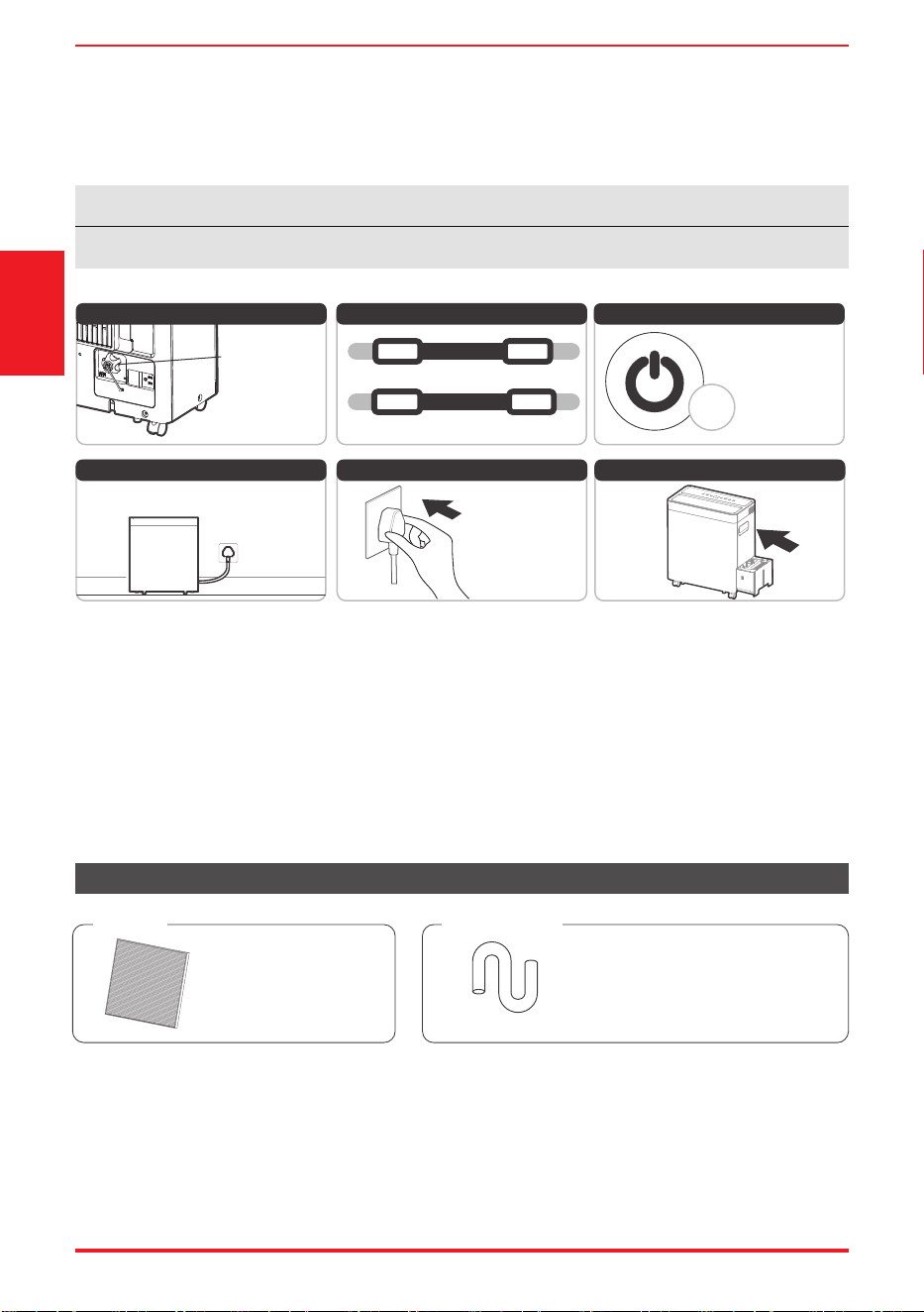
• 抽濕機兩側至少有 20 cm 空間,確保通風良好。(出風口至少有 40 cm 空間)
• 裝置放置區域的温度不低於 5 °C(41 °F)。盤管表面在温度低於 5 °C(41 °F)時可能會
結霜,從而降低性能。
• 裝置要遠離烘乾機、加熱器或散熱器。
• 在儲存書籍或貴重物品的任何地方使用裝置防止受潮損壞。
• 在地下室使用抽濕機,以防受潮。
抽濕機必須在封閉區域工作才能最有效。
• 執行一切傾斜和搬移操作前取出水桶,開啟連續排水口清空水,並斷開電源線。
了解產品
40 cm 或以上
20 cm 或以上
40 cm 或以上
40 cm 或以上
20 cm
或以上
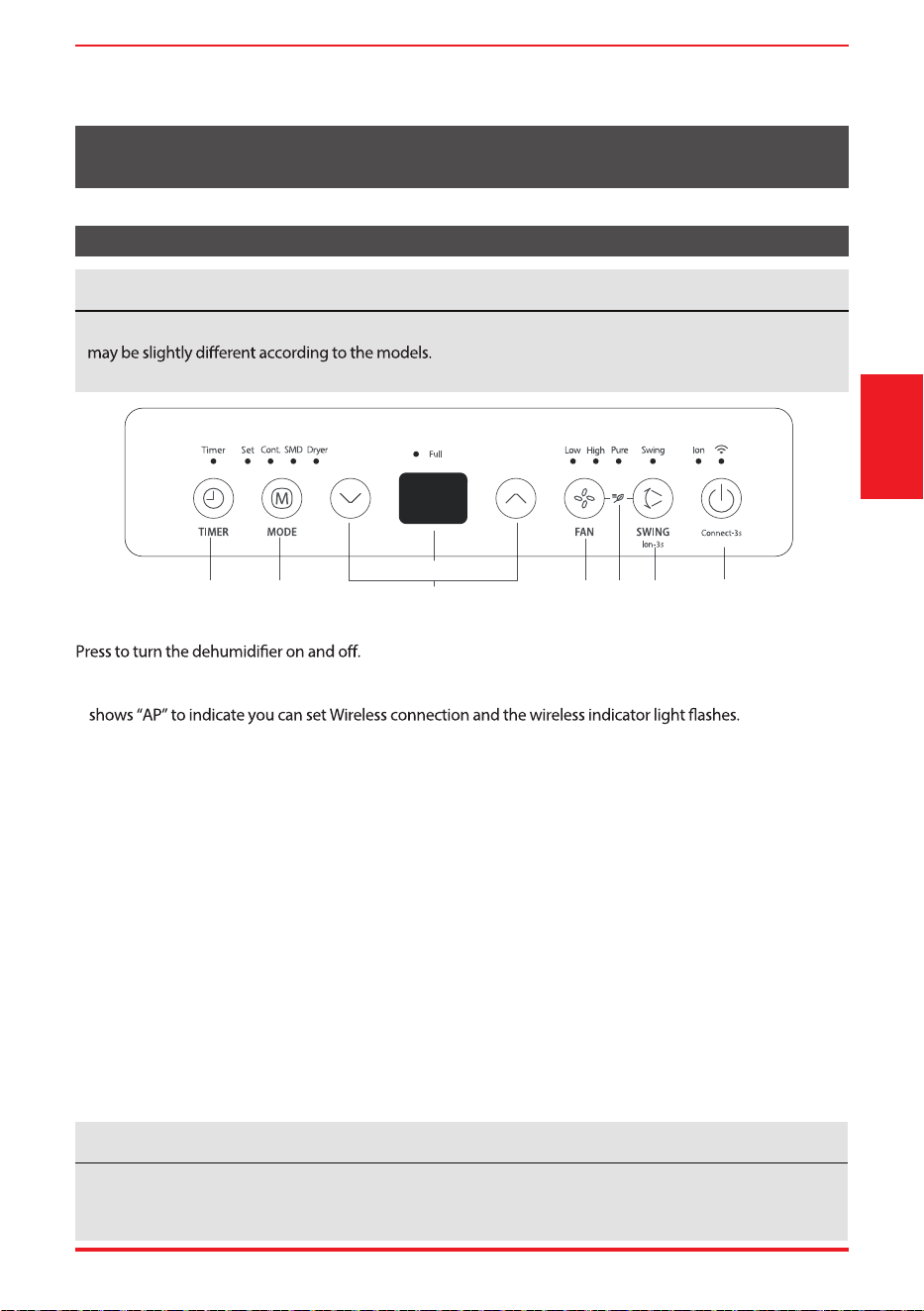
• 首次使用抽濕機時,請連續 24 小時運行裝置。確保在連續除濕模式下,塑料蓋安裝牢固,且不
會出現泄漏。
• 裝置設計的工作環境溫度介於 5 °C/41 °F 至 32 °C/90 °F,相對濕度介於 30% 至 80% 之間。
•
在開窗的開放空間使用時,產品表面可能形成冷凝,這是正常情況。
•
如果裝置已關機,需要快速重新開機,請留出大約三分鐘時間恢復正常運行。
•
不要連接抽濕機到多孔插座上,因為其他電器也在使用此插座。
•
選擇合適的位置,確保便於接入電源插座。
•
裝置應插入帶接地的電源插座。
•
確保水桶安裝正確,否則裝置將無法正常工作。
附件
注
桶內水位達到一定程度時,請小心移動機器,以免掉落。
頁面12
使用產品時
了解產品
30%(RH) 80%(RH)
工作温度
工作濕度
最小值
最小值
最大值
最大值
5 °C/41 °F
32 °C/90 °F
3分鐘
使用注意事項
確保水蓋安裝牢
固,且 24 小時持
續工作。
*請以實際插頭為
準,圖例僅供參考。
快速重啟後,等待 3 分
鐘恢復正常工作。
工作條件要求
接地連接
正確安裝水箱
正確連接電源
第一次使用
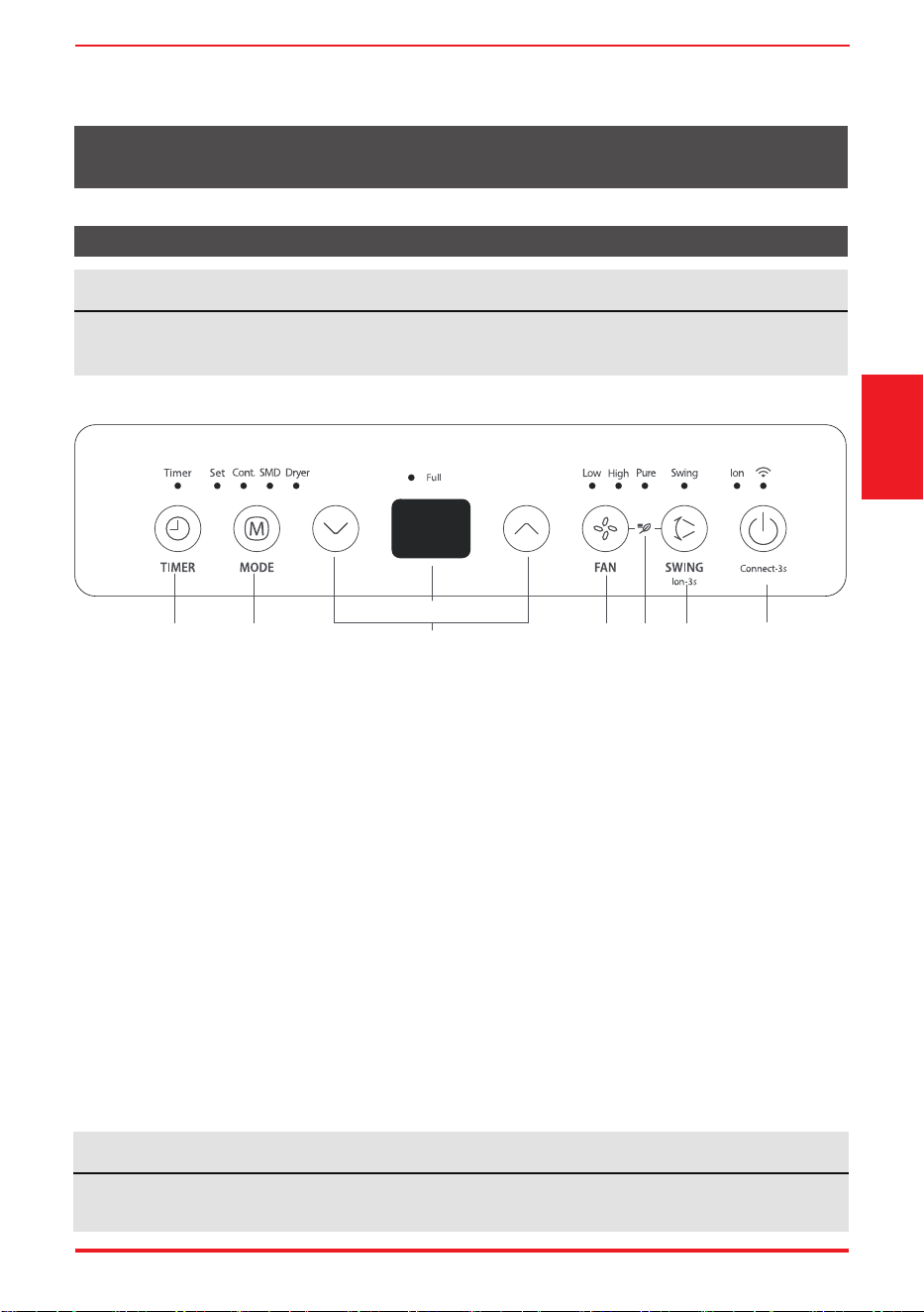
HEPA 過濾器(1 件)
排水軟管(1 件*)
提示:使用時拉直水管。
可選配件
配件
頁面13
了解功能
控制面板功能
注
以下控制面板僅用於解釋含義。您購買的裝置的控制面板可能會隨機型略有不同。
您的抽濕機可能不含某些指示燈或按鈕。具體情況以實際形狀為準。
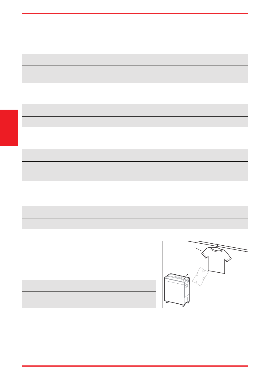
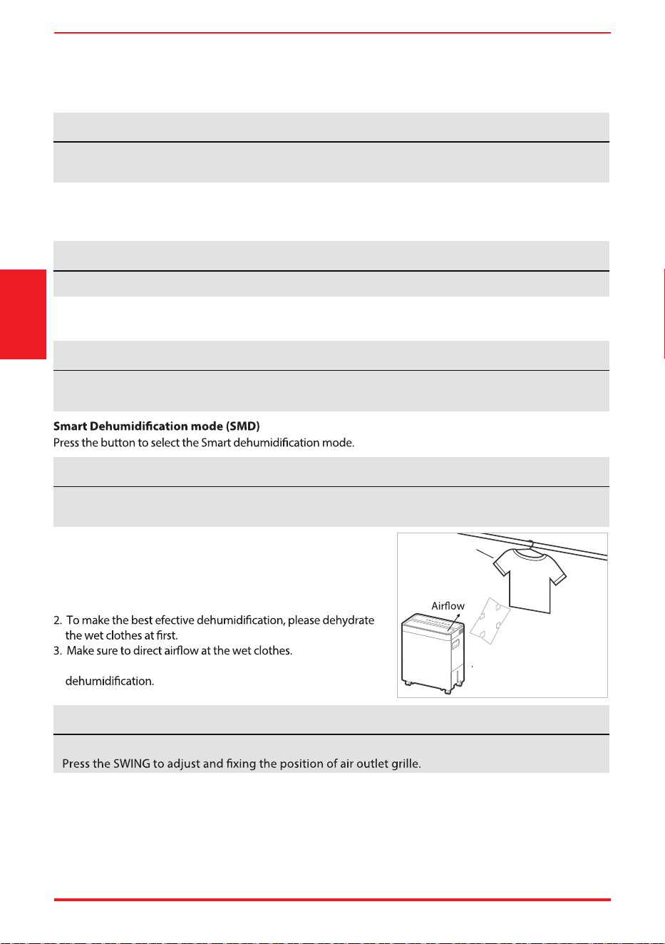
1. 電源開/關按鈕
按下可開啟和關閉抽濕機。
無線按鈕(某些機型專有)
1. 按住「電源」按鈕 3 秒鐘可啟動無線連接模式。LED 顯示屏顯示「AP」,表示您可以設置無線連接,
無線指示燈閃爍。
2. 如果 8 分鐘內連接(路由器)成功,抽濕機將自動退出無線連接模式,無線指示燈亮起,裝置進入
上一功能。如果在 8 分鐘內連接失敗,則抽濕機自動退出無線連接模式。
2. 定時器功能
按下此按鈕結合「向上」和「向下」按鈕可啟動自動開機和自動停機功能。
自動開機設置
1. 在關機狀態下,按下此按鈕激活自動開機時間。
2. 按下或長按「向上」或「向下」按鈕可將自動開機時間更改為按 0.5 小時遞增,直到 10 小時,然後
以 1 小時遞增,直到 24 小時。
3. 所選時間將在 5 秒內記錄,系統將自動恢復顯示濕度。此控制設置將倒計時直到剩餘時間,直到開機。
自動停止設置
1. 在啟動狀態下,按下此按鈕激活自動停機時間。
2. 按下或長按「向上」或「向下」按鈕可更改自動停止時間按 0.5 小時遞增,直到 10 小時,然後按 1
小時遞增,直到 24 小時。
3. 所選時間將在 5 秒內記錄,系統將自動恢復顯示濕度。此控制設置將倒計時剩餘時間,直到停止。
定時可以調節為按 24 小時增減。定時器設置完成後,您可以再次按下此按鈕檢查定時器設置狀態。
定時器設置完成後,您可以透過將設置時間設置為 0.0 來取消此設置。
注
了解功能
4
6/9
1
5
7
2 3
8
頁面14
3. 模式功能
按下此按鈕選擇您想要的模式,如圖所示:設置→ 連續→ SMD→乾燥
設置除濕模式(設置)
按下此按鈕選擇「除濕」模式,並透過按下「向上」和「向下」按鈕調整所需的濕度。
在「烘乾機」、「連續」和「SMD」模式下無法調整濕度設置;設定「設置」模式時會顯示設定
的濕度,5 秒後顯示環境濕度。
注
濕度可從 35% 設置到 85%,每次按壓可調節 5%。
注
連續除濕模式(連續)
按下此按鈕選擇連續除濕模式。
此模式下無法調節濕度
按壓援動装置調整並固定出風口的位置。
。
注
智能除濕模式(SMD)
按下此按鈕選擇智能除濕模式。
4. 向上和向下按鈕
濕度設置控制按鈕
濕度水平可以設置相對濕度在 35% RH 到 85% RH 的範圍內,增量為 5%。
定時器設置控制按鈕
按「向上」和「向下」按鈕設置自動開始和自動停止時間範圍為從 00:00 到 24:00。
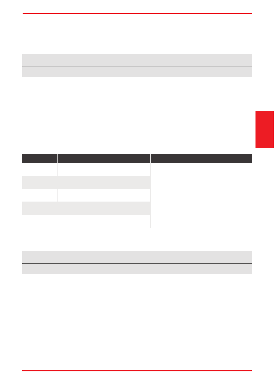
烘乾機模式(烘乾機)
按下此按鈕選擇烘乾機模式,在此模式下,機器將以連續除
濕和高速風扇方式運行。
1. 在此模式下工作時,請關閉門窗。
2. 為了最有效除濕,先使濕衣服脱水。
3. 確保氣流引向濕衣服。
4. 對於厚重的濕衣服,可能無法獲得最佳除濕效果。
此模式下無法調節濕度。本機會根據室温自動控制房間濕度在 45 % ~ 55 % 的舒適範圍內。
注
在烘乾機模式下無法調節濕度和風速。
注
了解功能
30~50 cm
濕衣服
30~50 cm 氣流
裝置頂部和右側與濕衣服
的距離為 30~50 cm。
按壓擺動裝置調整並固定出風口的位置。
風扇轉速指示燈在不同的風扇轉速設置下亮起。
注
每次啟動後,負離子功能也按預設開啟。
注
5. 風扇調速功能
按下此按鈕在以下設置中選擇風扇速度:低 → 高 → 低...
6. 擺動功能
按下此按鈕可開啟或關閉「擺動」功能。
7. 淨化功能
9. ION 功能(某些機型專有)
在啟動狀態下,長按「擺動」按鈕 3 秒可開啟 ION 功能。
更多功能
自動關機
當水桶裝滿時,或者取出水桶時,或者水桶沒有歸位時,抽濕機會關機。對於某些機型,風扇電機將
繼續運行 30 秒。水滿指示燈亮起時,請清空水桶並歸位,另一個問題是正確安裝水桶。然後,等待 3
分鐘再恢復運行,前 3 分鐘不能重啟。這是為了保護裝置。3 分鐘後將自動開始運行。
自動重啟
如果裝置因斷電而意外中斷運行,當電源恢復時,它將自動以先前的功能設置重啟。
8. 顯示屏
顯示環境濕度和設置濕度(濕度範圍:30% 至 90%);
顯示「定時器」設置(定時範圍:24 小時);
顯示錯誤代碼提醒。
頁面15
了解功能
錯誤代碼 可能原因 解決辦法
蒸發器盤管温度感應器出錯。
EH61
室温感應器出錯。
拔下裝置並重新插入。如果錯誤重複出現,請
聯絡製造商、其服務代理或有類似資質的人員
尋求服務。
EH60
室內 EEPROM 出錯。
EH00
顯示面板通訊出錯。EH0b
水桶裝滿水或水桶位置不對。
清空桶並換到正確位置。
P2
開啟或關閉電源時,短按「風扇」按鈕和「擺動」按鈕進入淨化功能,顯示屏顯示『ON』約3秒後,
將自動啟動淨化功能,並同時停止抽濕功能。
不要拉出整個水桶,否則會損壞水桶,甚至使你受傷。
注
頁面16
傾倒積水
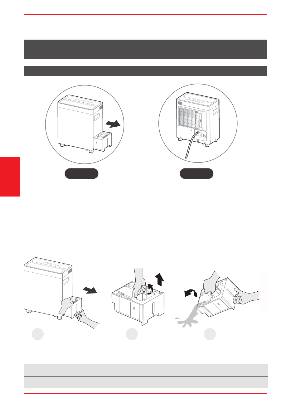
有兩種方法可以排出積水。
1
上提把手,
慢慢垂直提起水桶。
2
水桶拉出一半。
3
把水倒出來。
傾倒積水
• 裝置停止運行時,如果水桶已滿,則水滿指示燈會亮起。
• 裝置運行時,如果水桶已滿,則壓縮機和風扇停止運行,水滿指示燈亮起,數碼屏顯示 P2。
• 水桶拉出一半,然後上拉把手,慢慢垂直提起水桶,防止飛濺。
• 把水倒掉,使水桶復位。水桶必須放在正確的位置,並牢牢固定在抽濕機上才能運行。
• 當水桶放置到正確位置時,裝置才會重啟。
水桶排水
類型1: 類型2:
水桶排水 (類型 1)
水管排水
(連續)
某些機型含有內螺紋端。
注
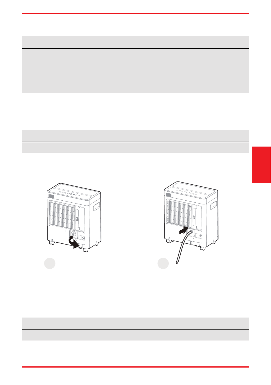
不使用連續排水功能時,從出口拆下排水軟管,並擦乾連續排水軟管出口。
注
注
1
拆下水蓋。
2
連接排水軟管。
傾倒積水
透過將裝置水管(ID≥Φ5/16",不含)連接到含有內螺紋端(ID:M=1”,不含),水流可以自動
排空到地漏。
從機器後排水口取下水蓋並放在一邊,然後將排水管穿過機器排水口插入排水管,並將排水管引至地
漏或合適的排水設施。
水管排水(連續) (類型 2)
• 取下水桶時,不得觸摸裝置內部的任何部件。因為這樣做可能損壞產品。水桶務必輕輕一直推
入到裝置中。水桶撞擊任何東西或未能安全推入可能會導致裝置無法運行。
• 如果裝置中有一些水,取出水桶時,則必須進行乾燥。
• 裝置運行時,如果取出水桶,則壓縮機和風扇停止運行,然後裝置將發出 8 次嗶嗶聲,數碼屏
顯示 Eb。
• 裝置停止運行時,如果取出水桶,裝置將發出 8 次嗶嗶聲,數碼屏顯示 Eb。
• 取下塑料蓋時,如果裝置的後排水口有一些水,必須擦乾。確保軟管牢固,不會產生泄漏,
軟管末端水平或向下,讓水順暢流動。
• 引導軟管至排水管,確保無扭結阻止水流。確保水管低於裝置的排水管出口。
• 在裝置上選擇所需的濕度設置和風扇速度,以便持續排水。
頁面17
保養與維修
抽濕機的護理和清潔——在清潔前使抽濕機斷電,從牆壁插座上取下插頭。
注
無用洗碗機清洗水桶。清潔後,水桶必須就位並固定牢固,以便抽濕機運行。
注
請勿沖洗空氣過濾器或放入自動洗碗機中。
• 加入清水和柔性清潔劑。勿使用漂白劑或研磨劑。
• 水不要直接濺到主機上。這樣做可能會導致電擊,導致絕緣層退化,或引起裝置生鏽。
• 進氣口和出氣口格柵容易弄髒,所以使用真空配件或刷子清潔。
頁面18
清潔格柵和外殼
• 每隔幾週清潔水桶,以防生長各類細菌。桶中裝入部分清水,加入少量柔性清潔劑。在桶裏來回晃動,
沖洗後倒掉。
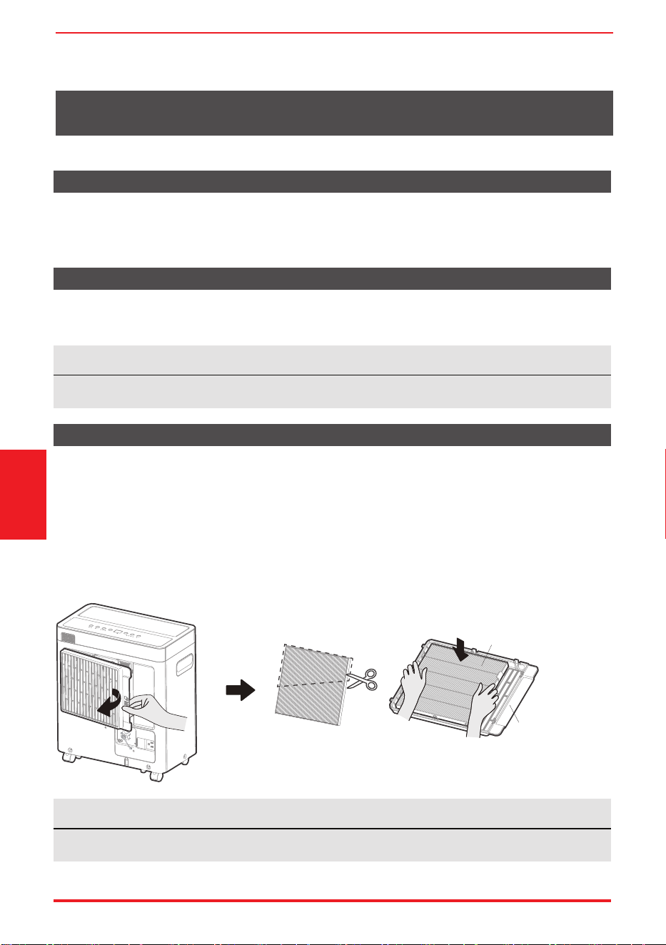
• 按下空氣過濾器上的拉環並向外拉,然後取出。
• 用温肥皂水清潔空氣過濾器。在更換之前沖洗並讓過濾器乾燥。
前格柵後面的空氣過濾器應至少每兩週檢查和清潔一次,必要時更頻繁。
清潔水桶
清潔空氣過濾器
保養與維修
取出方法:
• 如圖所示卸下空氣過濾器(進氣格柵),安裝HEPA過濾器,然後重新裝入機器。
• 建議每 6 個月更換一次 HEPA 過濾器。
提示:首次使用 HEPA 過濾器前,務必取下塑料密封膜。
HEPA 過濾器
空氣過濾器
安裝方法:
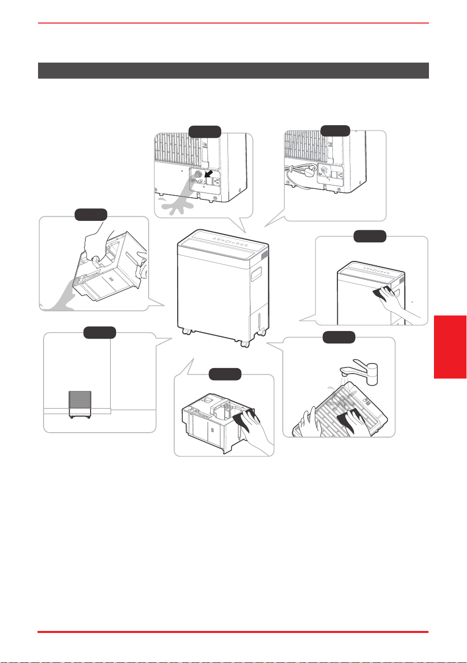
有關第 4-6 步的説明,請參閲「保養與維修」。
長期不用機器時
保養與維修
頁面19
第 4 步
第 5 步
第 1 步
第 6 步
第 7 步
第 2 步
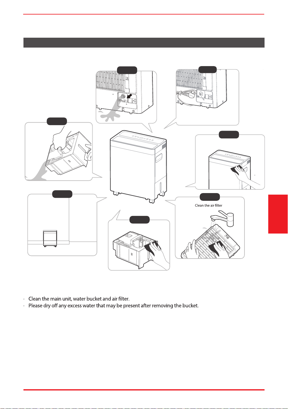
拔下水蓋排出多餘水分。
清潔格柵和外殼。
清潔空氣過濾器
清潔水桶
直立存放機器在乾燥、通風良好的地方。
倒掉桶中的水。
重新插入水蓋到機器的背面,使其安
裝到位。
第 3 步
• 清潔主機、水桶和空氣過濾器。
• 卸下水桶後擦乾可能存在的多餘水分。
• 關閉機器後,等待一天再清空水桶,收集使用後可能進一步形成的冷凝水。
• 用電源線扎帶扎緊電線。
• 正確儲存水桶,豎直放置機器。
• 用塑料袋蓋住機器。
• 直立存放機器在乾燥、通風良好的地方。
設計和規格如有變更,恕不另行通知產品改進。
欲知詳情,請諮詢銷售代理或製造商。手冊的任何更新都將上載到服務網站,請檢查獲取最新版本。
故障排除
頁面20
故障排除
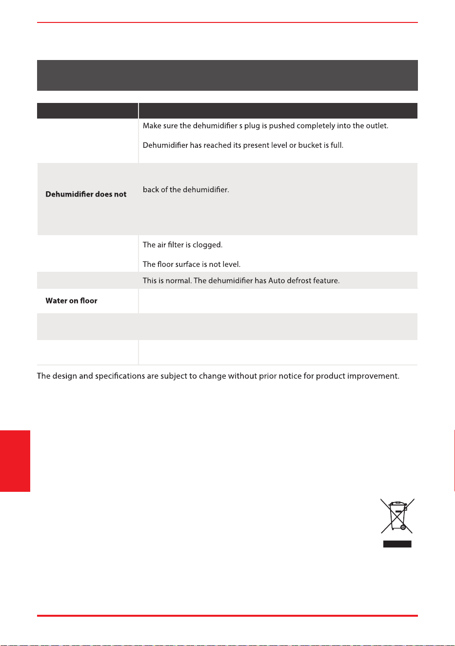
問題 檢查內容
機器未啟動
確保抽濕機插頭完全推入插座。
檢查房屋保險絲/斷路器盒。
抽濕機已達到其當前液位或水桶已滿。
水桶未安裝到位。
空氣過濾器堵塞。
機器傾斜放置,本應直立。
地板表面不平。
軟管接頭或軟管連線可能鬆動。
打算用水桶取水,但是後部排水蓋被拔出。
這種情況很正常。抽濕機具有自動除霜功能。
這些是錯誤代碼和保護代碼。
請參閲《了解功能》章節。
壓縮機每連續工作 8 小時,停機 10 分鐘。
預留除濕時間不夠。
確保抽濕機的正面或背面無窗簾、百葉窗或傢俱阻擋。
濕度控制設定值不夠低。
檢查所有門窗和其他開口是否關牢。
室温太低,低於 5 °C(41 °F)。
房間裏有煤油加熱器或散發水蒸氣的東西。
抽濕機不按預期乾燥空氣
機器工作時噪音大
盤管上出現結霜
地板積水
壓縮機不工作
顯示屏中出現 EH00、
EH60、EH61、P2
正確處理該產品:
這種標誌表示在整個歐盟中,這種產品不宜與其他家庭垃圾一起處理。為避免因為不受控制的垃圾處理而
對境或人身健康造成潜在傷害,回收垃圾以促進材料资料的可持續重複利用。要想回收用過的設備,請使
用回收或收集系統或聯繁產品零售商。他們可以確保該產品回收環保安全。
6.產品廢棄處理


# MatterDetails
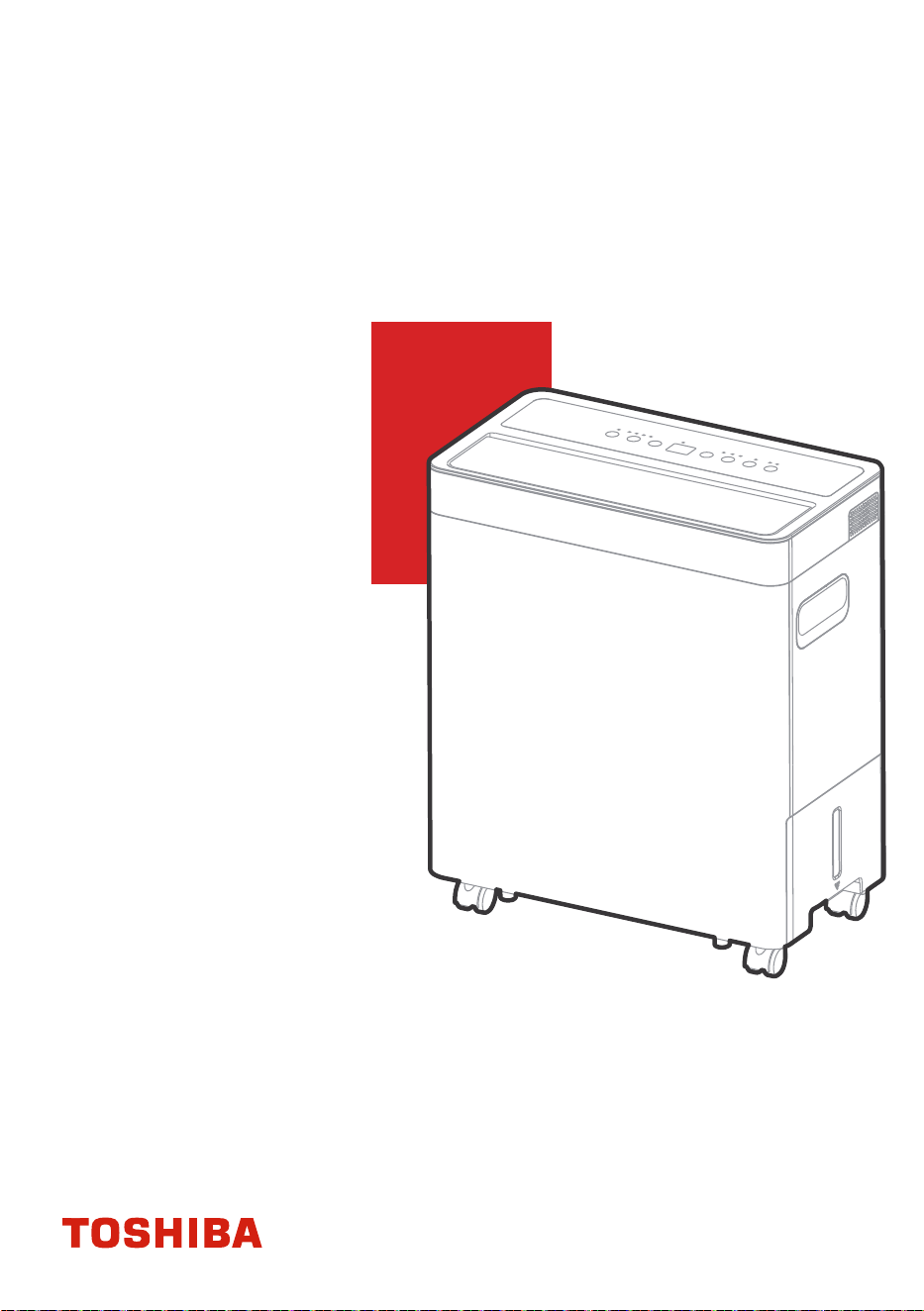
USER MANUAL
Warning notices: Before using this product,
please read this manual carefully and keep
it for future reference.
Dehumidier & Air Purier 2 In 1
RAD-DA11HK-1
RAD-DA13HK

Page 2
Directory
GET TO KNOW YOUR PRODUCT.......................................12
SAFETY PRECAUTIONS.......................................................3
Positioning the unit
Identifcation of parts
When using your product
Control Panel Features
GET TO KNOW YOUR FEATURES.....................................15
TROUBLESHOOTING.........................................................22
Bucket drainage (Type 1)
DUMP THE COLLECTED WATER.......................................18
Clean the Grille and Case
CARE AND MAINTENANCE...............................................20
Clean the bucket
Clean the air ter
When not using the unit for long time periods
Water hose drainage (continuous) (Type 2)
Page 3
Safety
Precautions
SAFETY PRECAUTIONS
Explanation of Symbols
It’s really important you read Safety Precautions Before Operation and Installation Incorrect installation
due to ignoring instructions can cause serious damage or injury.
The seriousness of potential damage or injuries is classied as either a WARNING or CAUTION.
Read these operating instructions carefully and attentively before using/commissioning the unit and keep
them in the immediate vicinity of the installation site or unit for later use!
WARNING
The signal word indicates a hazard with a high level of risk which,
if not avoided, may result in serious injury or death.
CAUTION
The signal word indicates a hazard with a low degree of risk which,
if not avoided, may result in minor or moderate injury.
• Do not exceed the rating of the power outlet or connection device.
• Do not operate or stop the unit by switching on or o the power.
• Do not modify power cord length or share the outlet with other appliances.
• Do not damage or use an unspecied power cord.
• Do not insert or pull out plug with wet hands.
• Do not install the appliance in a location that may be exposed to combustible gas.
• Do not place the unit near a heat source.
• Disconnect the power if strange sounds, smell, or smoke comes from it.
• You should never try to take apart or repair the unit by yourself.
• Before cleaning, turn of the power and unplug the unit.
• Do not use the machine near ammable gas or combustibles, such as gasoline, benzene, thinner,
etc.
• Do not drink or use the water drained from the unit.
• Do not put in places where water may splash onto the unit.
Place the unit on a level, sturdy section of the oor.
• Do not cover the intake or exhaust openings with cloths or towels.
• Care should be taken when using the unit in a room with the following persons:
infants, children, elderly people, and people not sensitive to humidity.
• Do not use in areas where chemicals are handled.
• Never insert your nger or other foreign objects into grills or openings. Take special care to warn
children of these dangers.
• Do not place heavy object on the power cord and take care so that the cord is not compressed.
• Do not climb up on or sit on the unit.
• Always insert the air lters securely. Clean air lter once every two weeks.
• If water enters the unit, turn the unit of and disconnect the power, contact a qualied service
technician.
• Do not place ower vases or other water container on top of the unit.
• Do not use extension cords.
• Do not take the water bucket out during operation.
WARNING
Page 4
Safety
Precautions
CAUTION
• This appliance can be used by children aged from 8 years and above and person with reduced
physical, sensory or mental capabilities or lack of experience and knowledge if they have been
given supervision or instruction concerning use of the appliance in a safe way and understand the
hazards involved. Children shall not play with the appliance. Cleaning and user maintenance shall
not be made by children without supervision. (be applicable for the European Countries)
CAUTION
• The manufactures nameplate is located on the rear panel of the unit and contains electrical and
other technical data specic to this unit.
• Be sure the unit is properly grounded. To minimize shock and re hazards, proper grounding is
important. The power cord is equipped with a three-prong grounding plug for protection against
shock hazards.
• Your unit must be used in a properly grounded wall receptacle. If the wall receptacle you intend to
use is not adequately grounded or protected by a time delay fuse or circuit breaker (please refer to
the nameplate for the electrical data), have a qualied electrician install the proper receptacle.
• Do not operate your appliance in a wet room such as a bathroom or laundry room. The unit’s circuit
board (PCB) is designed with a fuse to provide overcurrent protection.
• This appliance is not intended for use by persons (including children) with reduced physical,
sensory or mental capabilities or lack of experience and knowledge, unless they have been given
supervision or instruction concerning use of the appliance by a person responsible for their safety.
Children should be supervised to ensure that they do not play with the appliance. (be applicable
for other countries except the European Countries)
• If the supply cord is damaged, it must be replaced by the manufacturer, its service agent or
similarly qualied persons in order to avoid a hazard.
• Prior to cleaning or other maintenance, the appliance must be disconnected from the supply
mains.
• Do not install the appliance in a location that may be exposed to combustible gas.
• If combustible gas accumulates around the unit, it may cause re.
• If the appliance is knocked over during use, turn o the unit and unplug it from the main power
supply immediately. Visually inspect the unit to ensure there is no damage. If you suspect the unit
has been damaged, contact a technician or customer service for assistance.
• In a thunderstorm, the power must be cut o to avoid damage to the machine due to lightning.
• Do not run cord under carpeting. Do not cover cord with throw rugs, runners, or similar coverings.
Do not route cord under furniture or appliances. Arrange cord away from trafc area and where it
will not be tripped over.
• Do not operate unit with a damaged cord or plug. Discard unit or return to an authorized service
facility for examination and/or repair.
• To reduce the risk of re or electric shock, do not use this fan with any solid-state speed control
device.
• The appliance shall be installed in accordance with national wiring regulations.
• Contact the authorized service technician for repair or maintenance of this unit.
Turn of the product when not in use.
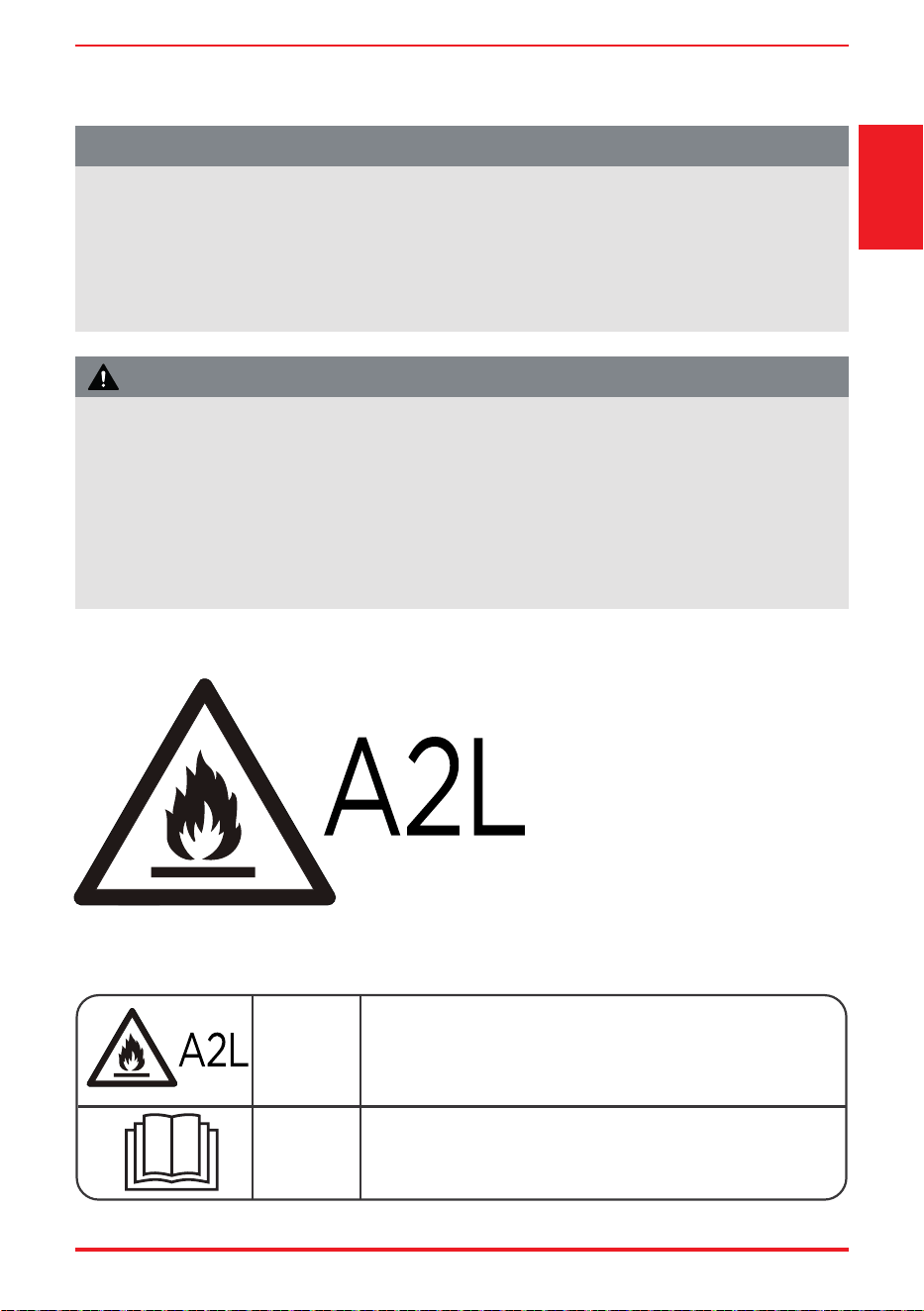
Note about Fluorinated Gasses (Not applicable to the unit using R290 Refrigerant)
•
Fluorinated greenhouse gases are contained in hermetically sealed equipment.
For specic information on the type, the amount and the CO2 equivalent in tones of the
uorinated greenhouse gas (on some models), please refer to the relevant label on the unit itself.
•
Installation, service, maintenance and repair of this unit must be performed by a certied
technician.
•
Product uninstallation and recycling must be performed by a certied technician.
Page 5
Safety
Precautions
WARNING
(For products containing R32 refrigerant
comply with the IEC 60335-2-40:2022
standard only)
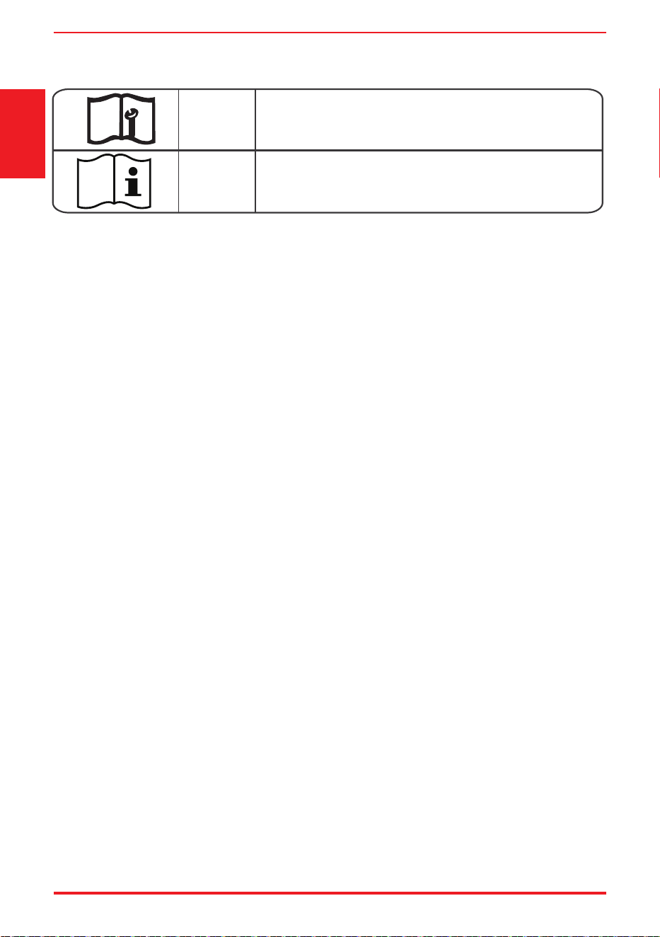
WARNING: FLAMMABLE MATERIAL
Explanation of symbols displayed on the indoor unit or outdoor unit
• Reusable mechanical connectors and ared joints are not allowed indoors.
• This unit is equipped with a leak detection system for safety. For leak detection to be eective, the
unit must be electrically powered at all times after installation, other than when servicing.
• Do not use means to accelerate the defrosting process or to clean, other than those recommended
by the manufacturer.
• The appliance shall be stored in a room without continuously operating ignition sources (for
example: open ames, an operating gas appliance or an operating electric heater).
• Do not pierce or burn.
• Be aware that refrigerants might not contain an odor.
WARNING
CAUTION
This symbol shows that this appliance used a ammable
refrigerant. If the refrigerant is leaked and exposed to
an external ignition source, there is a risk of re.
This symbol shows that the operation manual should be
read carefully.
Safety
Precautions
1. Installation (Space)
- That the installation of pipe-work shall be kept to a minimum.
- That pipe-work shall be protected from physical damage.
- Where refrigerant pipes shall be compliance with national gas regulations.
- That mechanical connections shall be accessible for maintenance purposes.
- In cases that require mechanical ventilation, ventilation openings shall be kept clear of obstruction.
- When disposing of the product is used, be based on national regulations, properly processed.
2. Servicing
- Any person who is involved with working on or breaking into a refrigerant circuit should hold a
current valid certicate from an industry-accredited assessment authority, which authorizes their
competence to handle refrigerants safely in accordance with an industry recognized assessment
specication.
3. Maintenance and repair requiring the assistance of other skilled personnel shall be carried out under
the supervision of the person competent in the use of ammable refrigerants.
4. Be more careful that foreign matter (oil, water, etc.) does not enter the piping.
Also, when storing the piping, securely seal the opening by pinching, taping, etc.
5. All working procedure that afects safety means shall only be carried by competent persons.
7. The appliance shall be stored so as to prevent mechanical damage from occurring.
6.No minimum room area requirement.
8. For ducted products, the ducts connected to an appliance shall not contain a potential ignition source;
9. When connected via an air duct system to one or more rooms, the supply and return air shall be
directly ducted to the space. Open areas such as false ceilings shall not be used as a return air duct;
10. Avoid excessive vibration or pulsation to refrigerating piping
11. Joints shall be tested with detection equipment with a capability of 5g/year of refrigerant or better,
with the equipment in standstill and under operation or under a pressure of at least these standstill
or operation conditions after installation. Detachable joints shall NOT be used in the indoor side of
the unit (brazed, welded joint could be used).
12. When a FLAMMABLE REFRIGERANT is used, the requirements for installation space of appliance
and/or ventilation requirements are determined according to
-- The mass charge amount (M) used in the appliance,
-- The installation location,
-- The type of ventilation of the location or of the appliance.
13. Servicing shall be performed only as recommended by the manufacturer.
Page 6
CAUTION
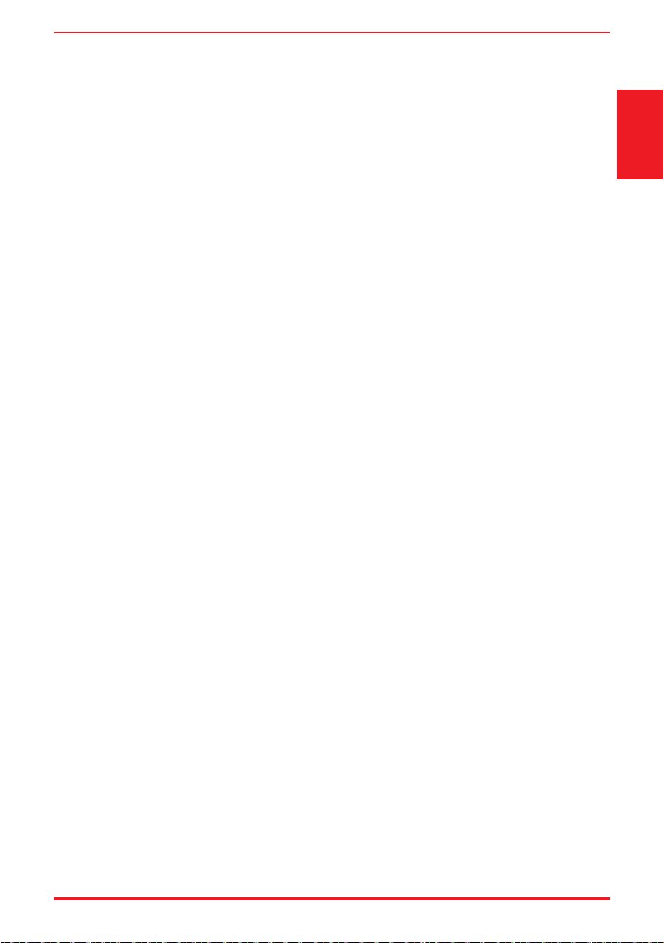
This symbol shows that a service personnel should be
handling this equipment with reference to the installation
manual.
CAUTION
This symbol shows that information is available such as the
operating manual or installation manual.
Safety
Precautions
14. When a FLAMMABLE REFRIGERANT is used, see the following requirements for installation
--That protection devices, piping, and ttings shall be protected as far as possible against adverse
environmental efects, for example, the danger of water collecting and freezing in relief pipes or the
accumulation of dirt and debris;
--That precautions shall be taken to avoid excessive vibration or pulsation to refrigerating piping;
--That piping in refrigeration systems shall be so designed and installed to minimize the likelihood of
hydraulic shock damaging the system;
--That provision shall be made for expansion and contraction of long runs of piping;
--That solenoid valves shall be correctly positioned in the piping to avoid hydraulic shock and shall
not block in liquid refrigerant unless adequate relief is provided;
--Steel pipes and components shall be protected against corrosion with a rustproof coating before
applying any insulation
--Field-made refrigerant joints indoors shall be tightness tested. The test method shall have a
sensitivity of 5 grams per year of refrigerant or better under a pressure of at least 0, 25 times the
maximum allowable pressure.
No leak shall be detected;
--Electrical components that can arc or spark, which are not considered ignition sources due to
compliance with 22.116.1 points b), c), d), or f) shall only be replaced with parts specied by the
appliance manufacturer.
Replacement with other parts may result in the ignition of refrigerant in the event of a leak;
15. Unventilated areas
--For appliances containing ammable refrigerants is installed in an unventilated area, please make
sure that it will not stagnate so as to create a re or explosion hazard for any refrigerant leak.
16. Qualication of workers
Any maintenance, service and repair operations must be required qualication of the working
personnel. Every working procedure that afects safety means shall only be carried out by competent
persons that joined the training and achieved competence should be documented by a certicate.
The training of these procedures is carried out by national training organizations or manufacturers
that are accredited to teach the relevant national competency standards that may be set in legislation.
All training shall follow the ANNEX HH requirements of IEC 60335-2-40:2022 Edition.
Examples for such working procedures are:
• Breaking into the refrigerating circuit;
• Opening of sealed components;
• Opening of ventilated enclosures.
Prior to beginning work on systems containing ammable refrigerants, safety checks are necessary to
ensure that the risk of ignition is minimized. For repair to the refrigerating system, the following
precautions shall be complied with prior to conducting work on the system.
1. Checks to the area
Works shall be undertaken under a controlled procedure so as to minimize the risk of a ammable gas
or vapor being present while the work is being performed.
2. Work procedure
All maintenance sta and others working in the local area shall be instructed on the nature of work
being carried out. Work in conned spaces shall be avoided.
3. General work area
Information on servicing
Page 7
Safety
Precautions
The area shall be checked with an appropriate refrigerant detector prior to and during work, to ensure
the technician is aware of potentially ammable atmospheres. Ensure that the leak detection
equipment being used is suitable foruse with ammable refrigerants, i.e., no sparking, adequately
sealed or intrinsically safe.
4. Checking for presence of refrigerant
If any hot work is to be conducted on the refrigeration equipment or any associated parts,
appropriate re extinguishing equipment shall be available to hand. Have a dry power or CO2 re
extinguisher adjacent to the charging area.
5. Presence of re extinguisher
No person carrying out work in relation to a REFRIGERATING SYSTEM which involves exposing any
pipe work shall use any sources of ignition in such a manner that it may lead to the risk of re or
explosion. All possible ignition sources, including cigarette smoking, should be kept suciently far
away from the site of installation, repairing, removing and disposal, during which refrigerant can
possibly be released to the surrounding space. Prior to work taking place, the area around the
equipment is to be surveyed to make sure that there are no ammable hazards or ignition risks.
“No Smoking” signs shall be displayed.
6. No ignition sources
Ensure that the area is in the open or that it is adequately ventilated before breaking into the system
or conducting any hot work. A degree of ventilation shall continue during the period that the work is
carried out. The ventilation should safely disperse any released refrigerant and preferably expel it
externally into the atmosphere.
7. Ventilated area
Where electrical components are being changed, they shall be t for the purpose and to the correct
specication. At all times the manufacturer’s maintenance and service guidelines shall be followed.
If in doubt consult the manufacturer’s technical department for assistance. The following checks
shall be applied to installations using FLAMMABLE REFRIGERANTS:
8. Checks to the refrigerating equipment
Repair and maintenance to electrical components shall include initial safety checks and component
inspection procedures. If a fault exists that could compromise safety, then no electrical supply shall be
connected to the circuit until it is satisfactorily dealt with. If the fault cannot be corrected immediately
but it is necessary to continue operation, and adequate temporary solution shall be used.
This shall be reported to the owner of the equipment so all parties are advised.
9. Checks to electrical devices
Initial safety checks shall include:
Page 8
•
the refrigerant charge is in accordance with the room size within which the refrigerant containing
parts are installed;
•
the ventilation machinery and outlets are operating adequately and are not obstructed;
•
if an indirect refrigerating circuit is being used, the secondary circuits shall be checked for the
presence of refrigerant;
•
marking to the equipment continues to be visible and legible, marking and signs that are illegible
shall be corrected;
•
refrigerating pipe or components are installed in a position where they are unlikely to be exposed
to any substance which may corrode refrigerant containing components, unless the components
are constructed of materials which are inherently resistant to being corroded or are suitably
protected against being so corroded.
•
That capacitors are discharged: this shall be done in a safe manner to avoid possibility of sparking
•
That there no live electrical components and wiring are exposed while charging, recovering or
purging the system;
•
That there is continuity of earth bonding.
Page 9
Sealed electrical components shall not be repaired.
10. Sealed electrical components
Check that cabling will not be subject to wear, corrosion, excessive pressure, vibration, sharp edges
or any other adverse environmental efects. The check shall also take into account the efects of aging
or continual vibration from sources such as compressors or fans.
11. Cabling
Under no circumstances shall potential sources of ignition be used in the searching for or detection
of refrigerant leaks. A halide torch (or any other detector using a naked ame) shall not be used.
The following leak detection methods are deemed acceptable for refrigerant systems. Electronic
leak detectors may be used to detect refrigerant leaks but, in the case of FLAMMABLE REFRIGERANTS,
the sensitivity may not be adequate, or may need re-calibration. (Detection equipment shall be
calibrated in a refrigerant-free area.) Ensure that the detector is not a potential source of ignition and
is suitable for the refrigerant used. Leak detection equipment shall be set at a percentage of the LFL
of the refrigerant and shall be calibrated to the refrigerant employed, and the appropriate
percentage of gas (25% maximum) is conrmed.
Leak detection uids are also suitable for use with most refrigerants but the use of detergents
containing chlorine shall be avoided as the chlorine may react with the refrigerant and corrode the
copper pipe-work.
NOTE Examples of leak detection uids are
- Bubble method,
- Fluorescent method agents.
If a leak is suspected, all naked ames shall be removed/extinguished.
If a leakage of refrigerant is found which requires brazing, all of the refrigerant shall be recovered
from the system, or isolated (by means of shut of valves) in a part of the system remote from the leak.
See the following instructions of removal of refrigerant.
12. Detection of ammable refrigerants
When breaking into the refrigerant circuit to make repairs - or for any other purpose conventional
procedures shall be used. However, for ammable refrigerants it is important that best practice be
followed, since ammability is a consideration. The following procedure shall be adhered to:
The refrigerant charge shall be recovered into the correct recovery cylinders. The manufacturer shall
specify the inert gases that can be used. Compressed air or oxygen shall not be used for purging
refrigerant systems.
NOTE an example of an inert gas is dry nitrogen.
Purging of the refrigerant circuit shall be achieved by breaking the vacuum in the system with inert
gas and continuing to ll until the working pressure is achieved, then venting to atmosphere, and
nally pulling down to a vacuum. This process shall be repeated until no refrigerant is within the
system. The system shall be vented down to atmospheric pressure to enable work to take place.
Ensure that the outlet of the vacuum pump is not close to any potential ignition sources and that
ventilation is available.
13. Refrigerant removal and circuit evacuation
•
Safely remove refrigerant following local and national regulations;
•
Evacuate;
•
Purge the circuit with inert gas (optional for A2L);
•
Evacuate (optional for A2L);
•
Continuously ush or purge with inert gas when using ame to open circuit; and
•
open the circuit
Safety
Precautions
Page 10
In addition to conventional charging procedures, the following requirements shall be followed:
Prior to recharging the system, it shall be pressure-tested with the appropriate purging gas. The
system shall be leak-tested on completion of charging but prior to commissioning. A follow up leak
test shall be carried out prior to leaving the site.
14. Charging procedures
Before carrying out this procedure, it is essential that the technician is completely familiar with the
equipment and all its detail. It is recommended good practice that all refrigerants are recovered
safely. Prior to the task being carried out, an oil and refrigerant sample shall be taken in case analysis
is required prior to re-use of recovered refrigerant. It is essential that electrical power is available
before the task is commenced.
a) Become familiar with the equipment and its operation.
b) Isolate system electrically
c) Before attempting the procedure ensure that:
d) Pump down refrigerant system, if possible.
e) If a vacuum is not possible, make a manifold so that refrigerant can be removed from various
parts of the system.
f) Make sure that cylinder is situated on the scales before recovery takes place.
g) Start the recovery machine and operate in accordance with instructions.
h) Do not overll cylinders (no more than 80% volume liquid charge).
i) Do not exceed the maximum working pressure of the cylinder, even temporarily.
j) When the cylinders have been lled correctly and the process completed, make sure that the
cylinders and the equipment are removed from site promptly and all isolation valves on the
equipment are closed of.
k) Recovered refrigerant shall not be charged into another refrigerating system unless it has been
cleaned and checked.
15. Decommissioning
Equipment shall be labelled stating that it has been de-commissioned and emptied of refrigerant.
The label shall be dated and signed. For appliances containing ammable refrigerants, ensure that
there are labels on the equipment stating the equipment contains ammable refrigerant.
16. Labelling
•
Ensure that contamination of dierent refrigerants does not occur when using charging
equipment. Hoses or lines shall be as short as possible to minimize the amount of refrigerant
contained in them.
•
Cylinders shall be kept in an appropriate position according to the instructions.
•
Mechanical handling equipment is available, if required, for handling refrigerant cylinders;
•
All personal protective equipment is available and being used correctly;
•
The recovery process is supervised at all times by a competent person;
•
Recovery equipment and cylinders conform to the appropriate standards.
•
Ensure that the refrigerating system is earthed prior to charging the system with refrigerant.
•
Label the system when charging is complete (if not already labelled).
•
Extreme care shall be taken not to overll the refrigerating system.
Safety
Precautions
Page 11
When removing refrigerant from a system, either for servicing or decommissioning,
it is required to follow good practice so that all refrigerants are removed safely.
When transferring refrigerant into cylinders, ensure that only appropriate refrigerant recovery
cylinders are employed. Ensure that the correct number of cylinders for holding the total system
charge is available. All cylinders to be used are designated for the recovered refrigerant and labelled
for that refrigerant (i.e., special cylinders for the recovery of refrigerant). Cylinders shall be complete
with pressure-relief valve and associated shut-of valves in good working order. Empty recovery
cylinders are evacuated and, if possible, cooled before recovery occurs.
The recovery equipment shall be in good working order with a set of instructions concerning the
equipment that is at hand and shall be suitable for the recovery of the ammable refrigerant.
Consult manufacturer if in doubt. In addition, a set of calibrated weighing scales shall be available
and in good working order. Hoses shall be complete with leak-free disconnect couplings and in
good condition.
The recovered refrigerant shall be processed according to local legislation in the correct recovery
cylinder, and the relevant waste transfer note arranged. Do not mix refrigerants in recovery units
and especially not in cylinders.
If compressors or compressor oils are to be removed, ensure that they have been evacuated to an
acceptable level to make certain that ammable refrigerant does not remain within the lubricant.
The compressor body shall not be heated by an open ame or other ignition sources to accelerate
this process. Draining of oil from a system shall be carried out safely.
17. Recovery
1. Transport of equipment containing ammable refrigerants Compliance with the transport
regulations.
2. Marking of equipment using signs Compliance with local regulations.
3. Disposal of equipment using ammable refrigerants Compliance with national regulations.
4. Storage of equipment/appliances
The storage of equipment should be in accordance with the manufacturer’s instructions.
5. Storage of packed (unsold) equipment
Storage package protection should be constructed such that mechanical damage to the
equipment inside the package will not cause a leak of the refrigerant charge.
The maximum number of pieces of equipment permitted to be stored together will be determined
by local regulations.
18. Transportation, marking and storage for units
Safety
Precautions
Page 12
Get To Know
Your Product
to change without prior notice.
GET TO KNOW YOUR PRODUCT
Design Notice
NOTE
All the illustrations in the manual are for explanation purpose only. Your machine may be slightly diferent.
The actual shape shall prevail. The unit can be controlled by the unit control panel.
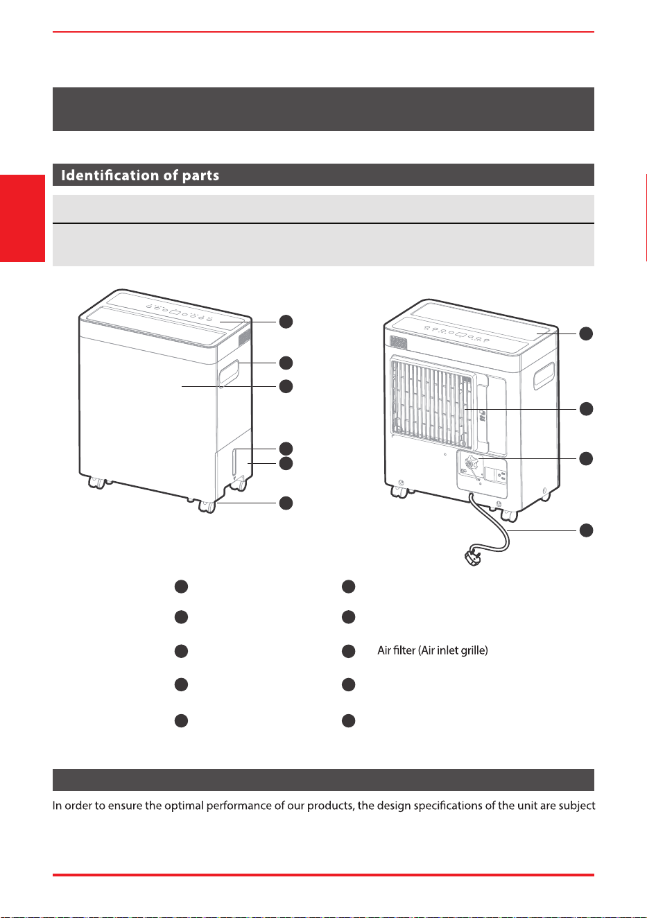
Front View Back View
1
2
3
4
5
6
7
8
9
Control panel
Handle (both sides)
Water level window
Front panel
Water bucket
Caster
Continuous drain hose outlet
Air outlet grille
10
Power cord and plug
7
8
9
10
1
2
3
4
5
6
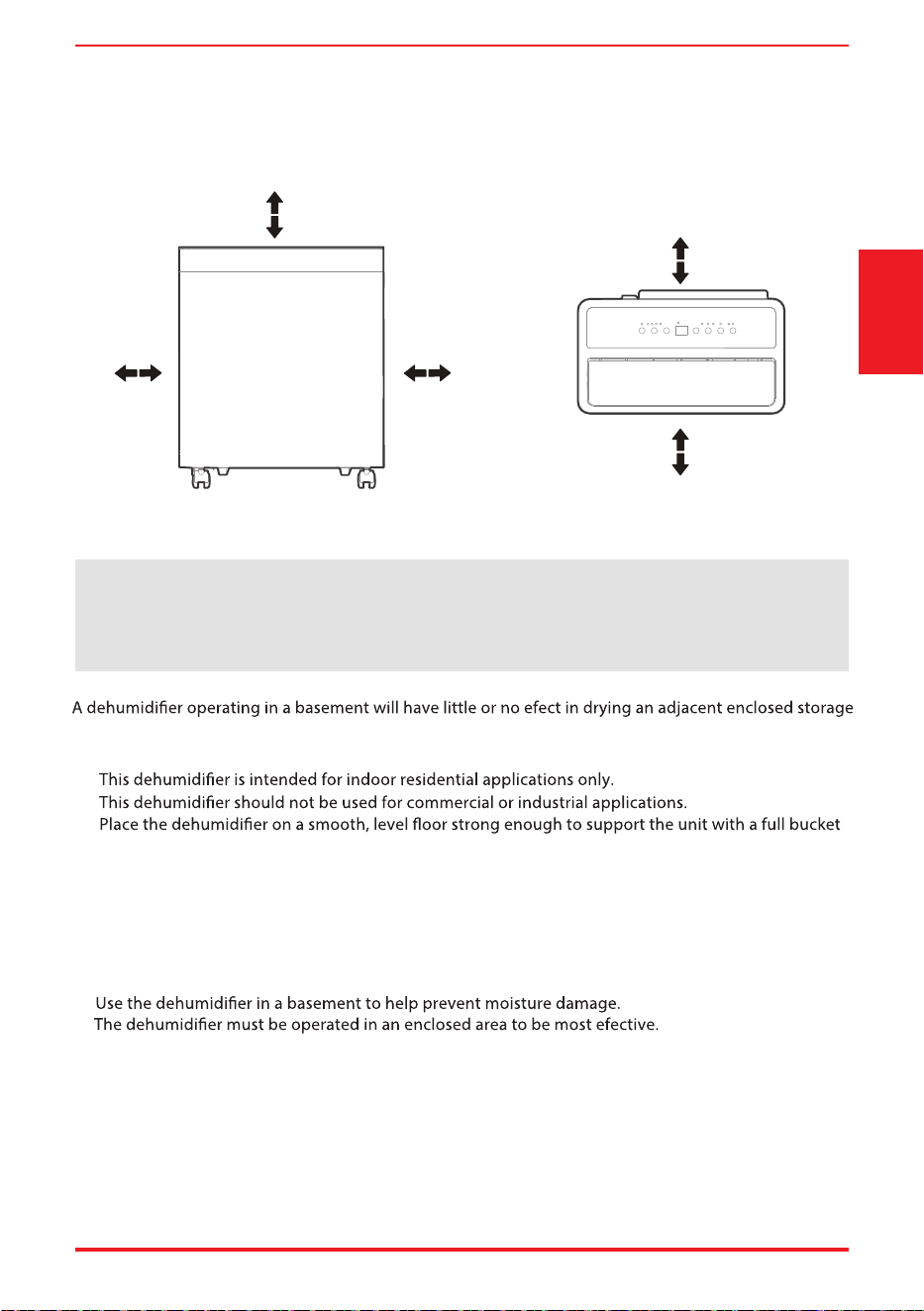
Casters (At four points on the bottom of unit)
40cm
or more
40cm
or more
40cm
or more
20cm
or more
20cm
or more
Page 13
Get To Know
Your Product
Positioning the unit
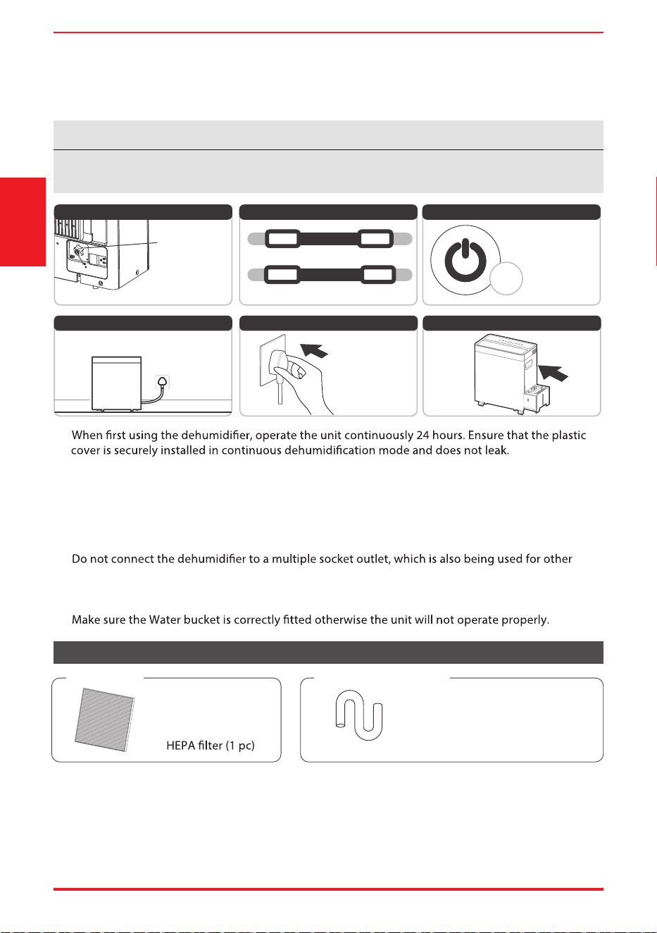
Front View Top View
• Casters can move freely.
• Do not force casters to move over carpet, nor move the unit with water in the bucket.
(The unit may tip over and spill water)
• Do not use outdoors.
•
•
•
of water.
• Allow at least 20cm of air space on all sides of the unit for good air circulation. (at least 40cm of air
space on air outlet)
• Place the unit in an area where the temperature will not fall below 5° C (41° F). The coils can become
covered with frost at temperatures below 5° C (41° F), which may reduce performance.
• Place the unit away from the clothes dryer, heater or radiator.
• Use the unit to prevent moisture damage anywhere books or valuables are stored.
•
• Before all tilting and moving operations, take out the bucket, open the continuous drain outlet to
empty the water, and disconnect the power cord.
area, such as a closet, unless there is adequate circulation of air in and out of the area.
When using your product
Page 14
Get To Know
Your Product
30%(RH) 80%(RH)
5 °C/41 °F
32 °C/90 °F
3
NOTE
Accessories
When the water in the bucket reaches to a certain level, please be careful to move the machine to avoid it
falling down.
Ensure the
installed and
operate the unit
continuously
24 hours.
After a quick restart,
wait 3 minutes for the
operation to resume.
*Please refer to
the actual plug,
and the legend
is for reference
only.
min
Min.
Operating TEMP.
Max.
Min.
Operating Humidity
Max.
First time using
Correct power connectio
n
Working condition requirement
Earth connection Proper installation of water tank
Precautions for use
•
• This unit is designed to operate with a working environment between 5 °C/41 °F and 32 °C/90 °F,
and between 30%(RH) and 80%(RH).
• When use in open space with open windows, condensation may form on the surface of the product,
which is normal.
• If the unit has been switched of and needs to be switched on again quickly, allow approximately
three minutes for the correct operation to resume.
•
electrical appliances.
• Select a suitable location, making sure you have easy access to an electrical outlet.
• Plug the unit into an electrical socket-outlet with earth connection.
•
Drain Hose (1 pc* )
NOTE: Make the
water pipe straight
when you use it.
Accessories Optional accessories
drain
cover is securely
Page 15
Get To Know
The Features
GET TO KNOW YOUR FEATURES
Control Panel Features
NOTE
The following control panels are for explanation purpose only. The control panel of the unit you purchased
Your machine may not contain some indicators or buttons. The actual shape shall prevail.
Wireless button (on some models)
1. Press and hold on the POWER button for 3 seconds to initiate the Wireless connection mode. The LED DISPLAY
2. If connection (router) is successful within 8 minutes, the unit will exit Wireless connection mode automatically
and the Wireless indicator illuminates and the unit enters the previous function. If connection is failure within
8 minutes, the unit exits the Wireless connection mode automatically.
1. POWER ON/OFF button
Press the button to initiate the Auto start and Auto stop function, in conjunction with the UP and DOWN buttons.
1. In the shutdown state, press the button to active the Auto start time.
2. Press or hold the UP or DOWN button to change the Auto start time by 0.5 hour increments, up to 10 hours,
then at 1 hour increments, up to 24 hours.
3. The selected time will register in 5 seconds and the system will automatically revert back to display the
humidity. The control will count down the time remaining until start.
2. TIMER Function
Auto start setting
1. In the startup state, press the button to active the Auto stop time.
2. Press or hold the UP or DOWN button to change the Auto stop time by 0.5 hour increments, up to 10 hours,
then at 1 hour increments, up to 24 hours.
3. The selected time will register in 5 seconds and the system will automatically revert back to display the
humidity. The control will count down the time remaining until start.
Auto stop setting
The timing can be adjusted to increase or decrease by 24 hours. After the TIMER setting is complete,
you can press the button again to check the TIMER setting status.
After the TIMER setting is complete, you can cancel it by setting the set time to 0.0.
NOTE
4
6/9
1
5
7
2 3
8
Press the button to select the mode you want, as shown: Set→ Cont.→ SMD→Dryer
3. MODE Function
The humidity level can be set within a range of 35% RH (Relative Humidity) to 85%RH(Relative Humidity) in 5%
increments.
4. UP and DOWN buttons
Humidity Set Control buttons
Press the UP and DOWN buttons to set the Auto start and Auto stop time from 00:00 to 24:00.
TIMER Set Control buttons
Press the button to select the Dehumidifying mode, and adjust the desired humidity by pressing the UP and
DOWN buttons.
Set Dehumidifying mode (Set)
Press the button to select the Continuous dehumidifying mode.
Continuous dehumidifying mode (Cont.)
Press the button to select the Dryer mode, and the unit will
operate in Continuous dehumidifying and
High fan speed
mode, in this mode.
1. Close doors and Windows while operating in this mode.
4. For thick and heavy wet clothes may not get the best efective
Dryer mode (Dryer)
The humidity setting cannot be adjusted in Dryer, Cont. and SMD; The set humidity will be displayed
when the mode is set to Set, and the ambient humidity will be displayed 5 seconds later.
NOTE
Humidity can be set from 35% to 85%, with 5% adjustment per press.
NOTE
Hu
Press the SWING to adjust and fxing the position of air outlet grille.
midity cannot be adjusted in this mode.
NOTE
Humidity cannot be adjusted in this mode. The unit will automatically control room humidity in a
comfortable range 45%~55% according to the room temperature.
NOTE
Humidity and wind speed cannot be adjusted in Dryer mode.
NOTE
Page 16
Get To Know
The Features
30~50 cm
Wet clothes
30~50cm
Allow 30~50cm of distance
on the top and right side of
the unit to the wet clothes.
Press the button to select fan speed in the following setting: Low → High → Low...
5. FAN speed Function
Press the button to turn the Swing function on or o.
6. SWING Function
7. PURIFICATION Function
Display ambient humidity and setting humidity (humidity range: 30% to 90%);
Display TIMER setting (timing range: 24 hours);
Display error codes reminder.
8. DISPLAY
In the startup state, press the SWING button for 3 seconds to turn on the ION function.
The dehumidier shuts of when the bucket is full, or when the bucket is removed or not replaced in the proper
position. For some models, the fan motor will continue to run for 30 seconds. When the Full indicator light
illuminates, please empty the bucket and reinstall it correctly, and the other problems are to install the bucket
correctly. Then, wait 3 minutes before resuming operation, it cannot be restarted operation in the rst 3 minutes.
This is to protect the unit. Operation will automatically start after 3 minutes.
9. ION Function (on some models)
The fan speed indicator light illuminates under diferent fan speed settings.
NOTE
After each startup, the negative ion function is also turned on by default.
NOTE
Page 17
Get To Know
The Features
Error codes Possible Causes Solution
Evaporator coil temperature sensor error.
EH61
Room temperature sensor error.
Unplug the unit and plug it back in. If the error
repeats, Contact the manufacturer, its service
agents or a similar qualied person for service.
EH60
Indoor EEPROM error.
EH00
Display panel communication error.
EH0b
Bucket is full of water or bucket is not in
right position.
Empty the bucket and replace it in the right
position.
P2
More Features
Auto Shut O
If the unit breaks o unexpectedly due to the power cut, it will restart with the previous function setting
automatically when the power resumes.
Auto-Restart
When the power is turned on or o, short press the FAN button and SWING button to enter the purication
function, when the display shows ‘ON’ for about 3 seconds, the purication function automatically starts, and
the dehumidifying function stops.
Page 18
Dump The
Collected Water
DUMP THE COLLECTED WATER
There are two ways to remove collected water.
Bucket drainage
Type 1: Type 2:
Water hose drainage
(continuous)
Bucket drainage (Type 1)
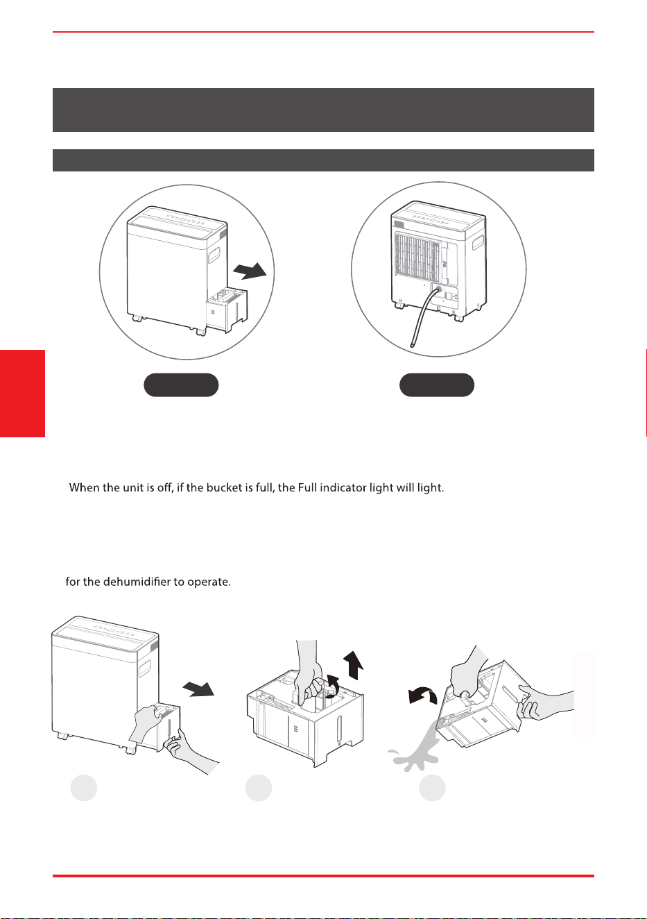
1
Pull up the handle
and lift the bucket
slowly vertically.
2
Pull the bucket out
halfway.
3
Pour the water out.
•
• When the unit is on, if the bucket is full, the compressor and the fan turn of, and the Full indicator
light will light, the digital display shows P2.
• Pull the bucket out halfway, then pull up the handle and lift the bucket slowly vertically to prevent
spatter.
• Throw away the water and replace the bucket. The bucket must be in right place and securely seated
• The appliance will re-start when the bucket is restored in its correct position.
Page 19
Dump The
Collected Water
NOTE
Do not pull out the whole bucket, or it may cause damage to the bucket or even injure you.
NOTE
On some models, the female threaded end is included.
NOTE
When the continuous draining feature is not being used, remove the drain hose from the outlet, and dry the
water in the continuous drain hose outlet.
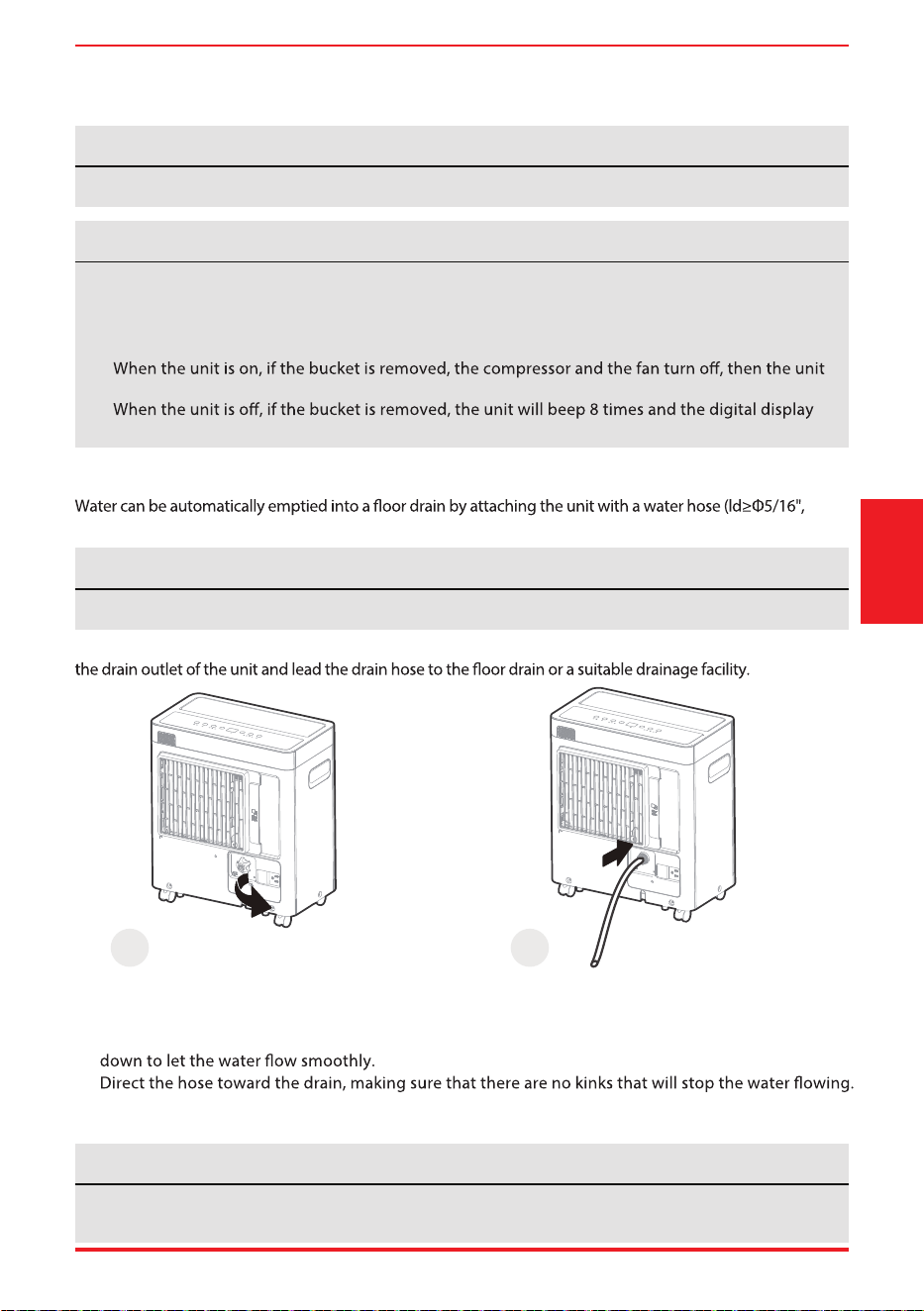
not included) with a female threaded end(ID:M=1",not included)
Remove the
from the back drain outlet of the unit and set aside, then insert the drain hose through
NOTE
Water hose drainage (continuous) (Type 2)
•
When you remove the bucket, do not touch any parts inside of the unit. Doing so may damage the
product. Be sure to push the bucket gently all the way into the unit. Banging the bucket against
anything or failing to push it in securely may cause the unit not to operate.
•
When you remove the plastic cover, if there is some water in the back drain outlet of the unit you
must dry it. Ma
ke sure the hose is secure so there are no leaks and the end of the hose is level or
•
Make sure the water hose is lower than the drain hose outlet of the unit.
•
Select the desired humidity setting and fan speed on the unit for continuous draining to start.
•
When you remove the bucket, if there is some water in the unit you must dry it.
•
will beep 8 times and the digital display shows Eb.
•
shows Eb.
1
Remove the drain cover.
2
Connect the drain hose.
drain cover
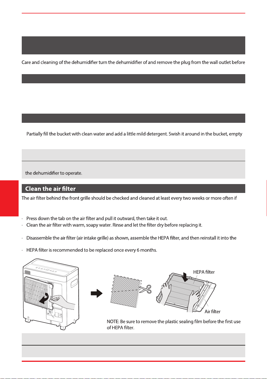
To remove:
Page 20
Care And
Maintenance
NOTE
Do not use a dishwasher to clean the bucket. After clean, the bucket must be in place and securely seated for
NOTE
DO NOT RINSE OR PUT THE AIR FILTER IN AN AUTOMATIC DISHWASHER.
cleaning.
· Use water and a mild detergent. Do not use bleach or abrasives.
· Every few weeks, clean the bucket to prevent growth of mold, mildew and bacteria.
and rinse.
To attach:
machine.
· Do not splash water directly onto the main unit. Doing so may cause an electrical shock, cause the insulation
to deteriorate, or cause the unit to rust.
· The air intake and outlet grilles get soiled easily, so use a vacuum attachment or brush to clean.
CARE AND MAINTENANCE
Clean the Grille and Case
Clean the bucket
necessary.
Refer to Care and Maintenance for instruction on steps 4-6.
Page 21
· After turning of fthe unit, wait one day before emptying the bucket to collect any condensate that may
continue to form after use.
· Wrap the cord with the power cord buckle.
· Properly restore the bucket and place the unit in an upright position.
· Cover the unit with a plastic bag.
· Store the unit upright in a dry, well-ventilated place.
When not using the unit for long time periods
Care And
Maintenance
Step 4
Step 5
Step 1
Step 6
Step 7
Step 2
excess water.
Clean the grille and case.
Clean the bucket
Store the unit upright in a dry,
well-ventilated place.
Remove water from the bucket.
Re-insert the into the
the back of the unit to keep them
in place.
Step 3
Remove drain cover to drain any
drain cover
Check the house fuse/circuit breaker box.
Water bucket is not in the proper position.
Page 22
TROUBLESHOOTING
TROUBLESHOOTING
Problem
Unit does not start
dry the air as it should
The unit makes a loud
noise when operating
Frost appears on the coils
EH00,EH60,EH61,P2
appear in the display
The compressor has
stopped working
What to check
Do not allow enough time to remove the moisture.
Make sure there are no curtains, blinds or furniture blocking the front or
The humidity control may not be set low enough.
Check that all doors, windows and other openings are securely closed.
Room temperature is too low, below 5°C(41°F).
There is a kerosene heater or something giving of water vapor in the room.
The unit is tilted instead of upright as it should be.
Hose to connector or hose connection may be loose.
Intend to use the bucket to collect water, but the back drain cover is removed.
These are error codes and protection codes.
See the GET TO KNOW YOUR FEATURES section.
Whenever the compressor runs continuously for 8 hours, stop it for 10 minutes.
Consult with the sales agency or manufacturer for details. Any updates to the manual will be
uploaded to the service website, please check for the latest version.
6.Disposal of your appliance
Correct Disposal of this product: This marking indicates that this product should not be disposed with
other house hold wastes throughout the EU. To prevent possible harm to the environment or human
health from uncontrolled waste disposal,recycle it responsibly to promote the sustainable reuse of
material resources. To return your used device, please use the return and collection system or contact
the retailer where the product was purchased. They can take this product for environmental safe recycling




# MatterDetails
16120100A23836