User Manual
OPERATING INSTRUCTIONS
Preparation
Design and Compliance Notes
Design Notice:
In order to ensure the optimal performance of our products, the design specifi cations of the unit and remote control are subject to change without prior notice.
Energy Rating Information:
The Energy Rating for this unit is based on an installation using an unextended exhaust duct without adaptors A or B (as shown in the Installation section of this manual).
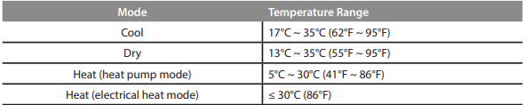
Unit Temperature Range
Exhaust Hose Installation:
The exhaust hose and adaptor must be installed or removed in accordance with the usage mode.
For COOL, HEAT (heat pump type) or AUTO mode, exhaust hose must be installed.
For FAN, DEHUMIDIFY or HEAT (electrical heat type) exhaust hose must be removed.
Control Panel Features
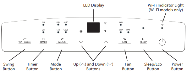
Swing Button
Used to initiate the Auto Swing feature. When the operation is ON, pressing the SWING button can stop the louver at the desired angle.
Timer button
Used to initiate the AUTO ON start time and AUTO OFF stop time program, in conjuction with the Up (  ) and Down (
 ) buttons. The timer on or off light will illuminate depending on the selected setting.
Fan button
Controls the fan speed. Press to control the fan speed in four steps - LOW, MID, HIGH and AUTO. The selected fan speed light (except AUTO) will illuminate. When AUTO is selected, no lights will illuminate.
Mode button
Selects the desired operating mode. Each time you press the button, a mode is selected in a sequence that goes from AUTO, COOL, DRY, FAN and HEAT (cooling only models excluded). The mode light illuminates and indicates the selected mode.
Up (  ) and Down (
  ) buttons
Used to adjust (increasing/decreasing) temperature settings in 1°C/1°F increments in a range of 17°C/62°F to 30°C/86°F or the TIMER setting in a range of 0 ~ 24hrs.
Power button
Power switch on/off .
Sleep (Eco)/Filter button
Used to initiate the SLEEP/ECO operation.
WI-FI Function
Available on Wi-Fi models only)
With the unit ON, press the VENT ANGLE/SWING button for 3 seconds to initiate the Wireless Connection mode. The LED display will display “AP” to indicate the wireless access point is available. Follow the instructions on the Wi-Fi setup manual and the latest app version available for your phone operating system. If the connection is successful, the unit will exit “AP” mode automatically and the Wi-Fi indicator light will illuminate. If connection is unsuccessful within 8 minutes, the unit exits “AP” mode and returns to regular operation.
If the Wi-Fi function is ON and there is a need to turn it off , press and hold the VENT ANGLE/SWING button and DOWN (-) button simultaneously for 3 seconds. The display will show “OFF” for 3 seconds and the Wi-Fi function will become inactive. To turn it back on, press and hold the VENT ANGLE/SWING button and UP (+) button simultaneously for 3 seconds. The display will show “ON” for 3 seconds. When you restart the wireless functions, it will take a period of time to connect to the network automatically. Always be sure your wireless connection is working properly and there is a valid internet connection for Wi-Fi functionality to work.
NOTE
When one of the above malfunctions occurs, turn off the unit and check for any obstructions. Restart the Unit. If the malfunction persists, turn off the unit and unplug the power cord. Contact the manufacturer or its service agents or a similar qualified person for service.
LED display
Shows the set temperature in °C (Degrees Celsius) or °F (Degrees Fahrenheit) and the Auto-timer settings. While on DRY and FAN modes, it shows the room temperature.
Shows Error codes and protection code:
E1 - Room temperature sensor error.
E2 - Evaporator temperature sensor error.
E3 - Condenser temperature sensor error (select models).
E4 - Display panel communication error.
P1 - Bottom tray is full - Connect the drain hose and drain the collected water away. If protection code repeats, call for service.
Operating Instructions
COOL operation
- Press the “MODE” button until the “COOL” indicator light comes on.
- Press the ADJUST buttons Up (
 ) or Down (
  ) to select your desired room temperature. The temperature can be set within a range of 17°C~30°C/62°F~86°F.
- Press the “FAN SPEED” button to choose the fan speed.
HEAT operation (available on HEAT models only)
- Press the “MODE” button until the “
 ” indicator light comes on.
- Press the ADJUST buttons Up (
 ) or Down (
  ) to select your desired room temperature. The temperature can be set within a range of 17°C~30°C/62°F~86°F.
- Press the “FAN SPEED” button to choose the fan speed. For some models, the fan speed cannot be adjusted while in HEAT mode.
DRY operation
- Press the “MODE” button until the “DRY” indicator light comes on.
- While in this mode, you cannot select a fan speed or adjust the temperature. The fan motor operates at LOW speed.
- Keep windows and doors closed for the best dehumidifying eff ect.
- Do not connect the duct to a window.
AUTO operation
- When you set the air conditioner to AUTO mode, it will automatically select cooling, heating (cooling only models excluded), or fan only operation depending on what temperature you have selected and the current room temperature.
- The air conditioner will control room temperature automatically according to the temperature point set by you.
- Under AUTO mode, you cannot select the fan speed.
FAN operation
- Press the “MODE” button until the ”FAN“ indicator light comes on.
- Press the “FAN SPEED” button to choose the fan speed. The temperature cannot be adjusted.
- Do not connect the duct to a window.
TIMER operation
- When the unit is on, pressing the Timer button will initiate the Auto-off stop program. The TIMER OFF indicator light illuminates. Press the Up or Down button to select the desired time. Press the TIMER button again within 5 seconds. The Auto-on start program is initiated and the TIMER ON indicator light illuminates. Press the Up or Down button to select the desired Auto-on start time.
- When the unit is off , press the Timer button to initiate the Auto-on start program. Pressing it again within five seconds will initiate the Auto-off stop program.
- Press or hold the Up or Down button to change the Auto time by 0.5 hour increments, up to 10 hours, then at 1 hour increments up to 24 hours. The control will count down the time remaining until start.
- The system will automatically revert back to display the previous temperature setting if there is no operation within 5 seconds.
- Turning the unit ON or OFF at any time or adjusting the timer setting to 0.0 will cancel the Auto Start/Stop timer program.
- Should a malfunction occur, the Auto Start/Stop timed program will also be cancelled.
SLEEP/ECO operation
Pressing this button will increase (during cooling operation) or decrease (during heating operation, applicable models) 1°C/1°F after 30 minutes. The temperature will again increase (cooling) or decrease (heating) by another 1°C/1°F after an additional 30 minutes. This new temperature will be maintained for 7 hours before returning to the originally selected temperature. This ends the Sleep/Eco mode and the unit will continue to operate as originally programmed.
Other Features
AUTO-RESTART
If the unit shuts off unexpectedly due to a power outage, it will restart with the previously set function automatically when the power resumes.
WAIT 3 MINUTES BEFORE RESUMING OPERATION
After the unit has stopped, it cannot be restarted until 3 minutes time has elapsed. This is to protect the unit. Operation will automatically resume after 3 minutes.
AIRFLOW DIRECTION ADJUSTMENT
The louver can be adjusted automatically. Adjust the airflow direction automatically.
- When the Power is ON, the louver opens fully.
- Press the SWING button on the panel or remote controller to initiate the Auto Swing feature. The louver willl swing up and down automatically.
- Please do not adjust the louver manually.
WATER DRAINAGE
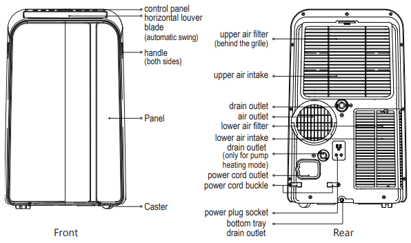
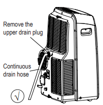
- During dehumidifying modes, remove the upper drain plug from the back of the unit and install the drain connector (5/8” universal female mender) with 3/4” hose (locally purchased). For models without drain connector, just attach the drain hose to the hole. Place the open end of the hose directly over the drain area in your basement floor.
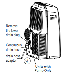
- During heating mode, remove the lower drain plug from the back of the unit and install the drain connector (5/8” universal female mender) with 3/4” hose (locally purchased). For models without drain connector, just attach the drain hose to the hole. Place the open end of the hose adaptor directly over the drain area in your basement floor.
NOTE
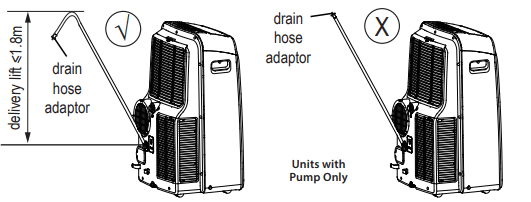
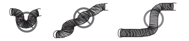
Make sure the hose is secure so there are no leaks. Direct the hose toward the drain, making sure that there are no kinks that will impede water flow. Place the end of the hose into the drain and make sure the end of the hose is directed downward to let the water flow smoothly. (See Figs with  ).
).
Installation not recommended. (See Figs with X ). When the continuous drain hose is not used, ensure that the corresponding drain plug and knob are installed firmly to prevent leakage.
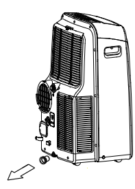
- When the water level of the bottom tray reaches a predetermined level, the unit beeps 8 times. The digital display shows “P1.” At this time the air conditioning/dehumidifi cation process will immediately stop. However, the fan motor will continue to operate (this is normal). Carefully move the unit to a drain location, remove the bottom drain plug and let the water drain away. Reinstall the bottom drain plug and restart the machine until the “P1” symbol disappears. If the error repeats, call for service.
INSTALLATION INSTRUCTIONS
Choosing the Right Location
Your installation location should meet the following requirements:
- Make sure that you install your unit on an even surface to minimize noise and vibration.
- The unit must be installed near a grounded plug, and the Collection Tray Drain (found on the back of the unit) must be accessible.
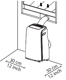
- The unit should be located at least 30 cm (12”) from the nearest wall to ensure proper air conditioning.
- DO NOT cover the Intakes, Outlets or Remote Signal Receptor of the unit, as this could cause damage to the unit.
Recommended Installation
NOTE
All images in the manual are illustrative. Your unit may be slightly different.
Tools Needed
- Medium Phillips screwdriver
- Tape measure or ruler
- Knife or scissors
- Saw (optional, to shorten window adaptor for narrow windows).
Accessories
Your Window Installation Kit fi ts windows 67.5-123 cm (26.5”-48”) and can be shortened for smaller windows.
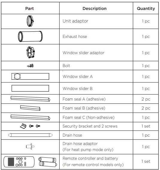
Window Installation Kit
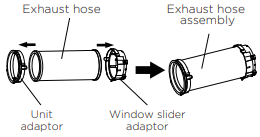
Step One: Preparing the exhaust hose assembly
Press the exhaust hose into the window slider adaptor and unit adaptor, clamp automatically by elastic buckles of the adaptors.
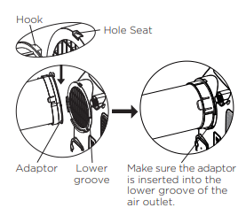
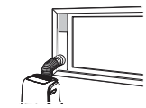
Step Two: Install the exhaust hose assembly to the unit
Insert unit adaptor of the Exhaust hose assembly into the lower groove of the air outlet of the unit with the hook of the adaptor aligned with the hole seat of the air outlet and slide down the Exhaust hose assembly along the direction indicated by the arrow for installation.
Step Three: Preparing the adjustable window slider
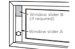
- Depending on the size of your window, adjust the size of the window slider.
- If the length of the window requires two window sliders, use the bolt to fasten the window sliders once they are adjusted to the proper length.
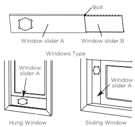
Type 1: Hung window installation
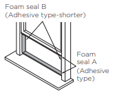
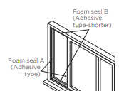
1. Cut the adhesive foam seal A and B strips to the proper lengths, and attach them to the window sash and frame as shown.
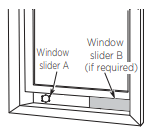
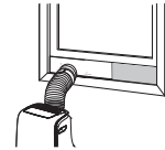
2. Insert the window slider assembly into the window opening.
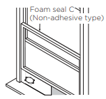
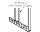
3. Cut the non-adhesive foam seal C strip to match the width of the window. Insert the seal between the glass and the window frame to prevent air and insects from getting into the room.
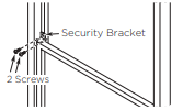
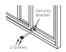
4. If desired, install the security bracket with 2 screws as shown.
5. Insert the window slider adaptor into the hole of the window slider.
Type 2: Sliding window installation
1. Cut the adhesive foam seal A and B strips to the proper lengths, and attach them to the window sash and frame as shown.
2. Insert the window slider assembly into the window opening.
3. Cut the non-adhesive foam seal C strip to match the window height. Insert the foam seal between the glass and the window frame to prevent air and insects from getting into the room.
4. If desired, install the security bracket with 2 screws as shown.
5. Insert the window slider adaptor into the hole of the window slider.
NOTE
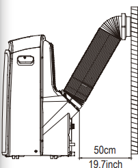
To ensure proper functioning, DO NOT overextend or bend the hose. Make sure that there is no obstacle around the air outlet of the exhaust hose (in the range of 500mm) in order for the exhaust system to work properly. All illustrations in this manual are for explanation purposes only. Your air conditioner may be slightly different. The actual shape shall prevail.
CARE AND CLEANING
Safety Precautions
- Always unplug the unit before cleaning or servicing.
- DO NOT use fl ammable liquids or chemicals to clean the unit.
- DO NOT wash the unit under running water. Doing so causes electrical danger.
- DO NOT operate the machine if the power supply was damaged during cleaning. A damaged power cord must be replaced with a new cord from the manufacturer.
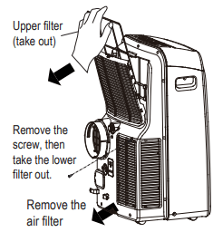
Air Filter Cleaning
CAUTION
DO NOT operate the unit without fi lter because dirt and lint will clog it and reduce performance.
Maintenance Tips
- Be sure to clean the air filter every 2 weeks for optimal performance.
- The water collection tray should be drained immediately after P1 error occurs, and before storage to prevent mold.
- In households with animals, you will have to periodically wipe down the grill to prevent blocked airfl ow due to animal hair
Unit Cleaning
Clean the unit using a damp, lint-free cloth and mild detergent. Dry the unit with a dry, lint-free cloth
Store the Unit When Not in Use
- Drain the unit’s water collection tray according to the instructions in the following section.
- Run the unit on FAN mode for 12 hours in a warm room to dry it and prevent mold.
- Turn off the unit and unplug it.
- Clean the air filter according to the instructions in the previous section. Reinstall the clean, dry filter before storing.
- Remove the batteries from the remote control.
TROUBLESHOOTING TIPS
Malfunction Diagnosis
Unit does not turn on when pressing ON/OFF button
- P1 Error Code.
- The water collection tray is full. Turn off the unit, drain the water from the water collection tray and restart the unit.
- In COOL mode: room temperature is lower than the set temperature.
Unit does not cool well
- The air filter is blocked with dust or animal hair.
- Turn off the unit and clean the filter according to instructions.
- Exhaust hose is not connected or is blocked.
- Turn off the unit, disconnect the hose, check for blockage and reconnect the hose.
- The unit is low on refrigerant.
- Call a service technician to inspect the unit and top off refrigerant.
- Temperature setting is too high.
- Decrease the set temperature.
- The windows and doors in the room are open.
- Make sure all windows and doors are closed.
- The room area is too large.
- Double-check the cooling area.
- There are heat sources inside the room.
- Remove the heat sources if possible.
The unit is noisy and vibrates too much
- The floor is not level.
- Place the unit on a flat, level surface.
- The air filter is blocked with dust or animal hair.
- Turn off the unit and clean the filter according to instructions.
The unit makes a gurgling sound
- This sound is caused by the flow of refrigerant inside the unit.
Unit stops frequently
- The exhaust hose is blocked, extended or otherwise restricted.
- Remove the exhaust hose to see if the unit continues to operate. If yes, shorten the extension, reduce the number of bends or eliminate restriction.
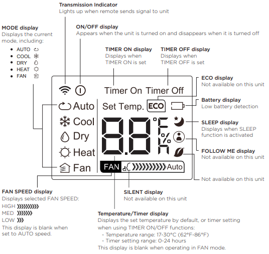
REMOTE CONTROL OPERATING INSTRUCTIONS
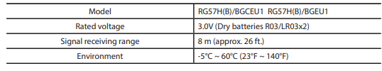
Remote Control Specifications
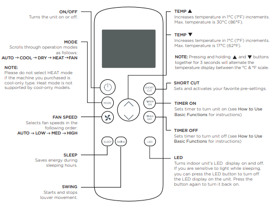
Function Buttons
Before you begin using your new air conditioner, make sure to familiarize yourself with its remote control. The following is a brief introduction to the remote control itself. For instructions on how to operate your air conditioner, refer to the Operating Instructions section of this manual.
Remote LED Screen Indicators