
USER MANUAL
Safety Precautions
Operating Instructions
Installation Instructions
Remote Control and
App Instructions
Troubleshooting Tips
Care and Cleaning
Portable Type
Room Air Conditioner
Warning notices: Before using this product,
please read this manual carefully and keep
it for future reference.
change without prior notice for product
improvement. Consult with your dealer or
the manufacturer for details.
0202 - 90 - C noisrev
U
SER MAN
U
AL
Safet
y
Precautions
O
peratin
g
Instruction
s
I
nst
a
ll
a
ti
o
n Instr
u
cti
o
ns
R
em
o
te C
o
ntr
ol
a
n
d
A
pp Instruct
i
ons
T
roubleshootin
g
Tip
s
C
are and Cleanin
g
RAC-PD0812CRR12CRRU
RARAC-PD1C-PD1013C013CWRWRUU
RARAC-PD121C-PD1213C3CWRWRUU
RAC-PD1414CWRU
Portable T
y
p
e
R
oo
m Air C
o
n
d
iti
o
ne
r
Warnin
g
notices: Be
f
ore usin
g
this product
,
please read this manual care
f
ull
y
and ke
ep
it
f
or
f
uture re
f
erenc
e.
T
he desi
g
n and speci cations are sub
j
ect t
o
chan
g
e without prior notice for produc
t
im
pr
ovement. Consu
l
t wit
h
yo
ur
d
ea
l
er o
r
the manu
f
acturer
f
or details
.
vers
io
n
C
- 09 - 202
0
www.toshiba-lifestyle.com
version A - 09 - 2022 (PREVIEW01)
Page 2 User Manual
Read This Manual
Inside you’ll find many helpful hints on how to use and maintain your air conditioner properly.
Just a little preventive care on your part can save you a great deal of time and money
over the life of your air conditioner. You’ll find many answers to common problems in the
troubleshooting tips - you should be able to fix most of them quickly before calling service.
These instructions may not cover every possible condition of use, so common sense and
attention to safety is required when installing, operating and maintaining this product.
User Manual
Safety Precautions .................................................................................................................... 3
Operating Instructions ............................................................................................................ 8
Installation Instructions ........................................................................................................ 13
Care and Cleaning .................................................................................................................. 18
Troubleshooting Tips ............................................................................................................. 19
Remote Control and App Instructions ............................................................................ 20
• For support, please call the Service Center at 1-855-204-5313.
• This appliance is not intended for use by persons (including children) with reduced physical,
sensory or mental capabilities or lack of experience and knowledge, unless they have been
given supervision or instruction concerning use of the appliance by a person responsible for
their safety.
• Children should be supervised to ensure that they do not play with the air conditioner.
• The appliance shall be installed in accordance with national wiring regulations.
• Do not operate your air conditioner in a humid room such as a bathroom or laundry room.
CAUTION

User Manual Page 3
Safety
Precautions
SAFETY PRECAUTIONS
To prevent injury to the user or other people and property damage, the instructions shown here must be
followed. Incorrect operation due to ignoring of instructions may cause harm or damage. The level of risk
is shown by the following indications.
WARNING
This symbol indicates a hazardous situation which, if not avoided,
could result in death or serious injury.
CAUTION
This symbol indicates a hazardous situation, which, if not avoided,
could result in minor or moderate injury.
NOTICE
This symbol addresses practices not related to physical injury.
• Be sure the air conditioner has been securely and correctly installed according to the
installation instructions in this manual. Save this manual for possible future use in removing or
installing this unit.
• Plug in power cord plug properly.
Otherwise, it may cause electric shock or re due to excess heat generation.
• Do not modify power cord length or share the outlet with other appliances as it may cause
electric shock or re due to overheating.
• Always ensure e ective grounding.
Incorrect grounding may cause electric shock.
• Unplug the unit if you notice unusual sounds or smells or smoke coming from it.
A damaged product may cause re and electric shock.
• Ventilate room before operating the air conditioner if there is a gas leakage from another
appliance.
• Do not operate or stop the unit by inserting or pulling out the power cord plug.
• Do not operate with wet hands or in very humid environments.
It may cause electric shock.
• Do not allow water to come into contact with any electric parts.
It may cause failure or electric shock.
• Do not use the socket if it is loose or damaged.
It may cause re and electric shock.
• Do not use or keep the power cord close to heating appliances.
It may cause re and electric shock.
• Do not use any devices or materials for installation that are not recommended in this manual.
• Do not disassemble or modify unit.
It may cause failure and electric shock.
WARNING
Page 4 User Manual
Safety
Precautions
• Do not damage or use an alternate power cord.
It may cause re and electric shock.
If the power cord is damaged, it must be replaced by the manufacturer or an authorized service
center or a similarly quali ed person in order to avoid a hazard.
• Do not direct air ow straight into persons to avoid possible health hazard.
• Do not open the unit during operation.
It may cause electric shock.
• Do not use the power cord near ammable gas or combustibles, such as gasoline, benzene,
thinner, etc.
It may cause an explosion or re.
• Do not let children hang on the air conditioner or bracket.
A serious injury may occur.
• Avoid re hazard or electric shock. Do not use an extension cord or an adaptor plug. Do not
remove any prongs from the power cord.
• Be sure the air conditioner is properly grounded. To minimize shock and re hazards, proper
grounding is important. The power cord is equipped with a three-prong grounding plug for
protection against shock hazards.
• Your air conditioner must be used in a properly grounded wall receptacle. If the wall receptacle
you intend to use is not adequately grounded or protected by a time delay fuse or circuit
breaker, have a quali ed electrician install the proper receptacle. Ensure the receptacle is
accessible after the unit installation.
• Be sure the electrical service is adequate for the model you have chosen. This information can be
found on the serial plate, which is located on the side of the cabinet and behind the grille.
• When the air lter is to be removed, do not touch the metal parts of the unit.
It may cause injury.
• When the unit needs cleaning, switch o , and turn o the circuit breaker.
Do not clean unit when power is on as it may cause re, electric shock or injury.
• Do not place obstacles around air inlets or inside of air outlet.
It may cause failure or accident.
• Clean with a soft cloth only. Do not use strong detergents that contain wax or thinners as it may
damage the product.
• Use caution when unpacking and installing. Sharp edges could cause injury.
• Do not clean the air conditioner with water.
Water may enter the unit and degrade the insulation which could lead to electric shock.
• Do not put a pet or house plant where it will be exposed to direct air ow.
This could injure the pet or harm the plant.
WARNING
CAUTION
User Manual Page 5
• Hold the plug by the head of the power plug when taking it out.
Otherwise, it may cause electric shock and damage.
• Ensure that the installation is properly secured to prevent the product from potentially falling.
• Do not place heavy objects on the power cord and ensure that the cord is not compressed.
Otherwise, there is danger of re or electric shock.
• If water is spilled on the unit, turn o the unit and switch o the circuit breaker. Isolate supply by
taking the power-plug out and contact a quali ed service technician.
• Do not use near gas stove or other gas burning appliances, as air ow may a ect gas
combustion.
• Do not use for any purpose other than room comfort.
Do not use this air conditioner to preserve precision devices, food, pets, plants, and art objects.
It may cause deterioration.
• Turn o the main power switch if the unit is not to be used for an extended time.
• Always insert the lters securely. Clean lter once every two weeks.
Operation without lters may cause failure.
• Do not drink water drained from the air conditioner.
CAUTION
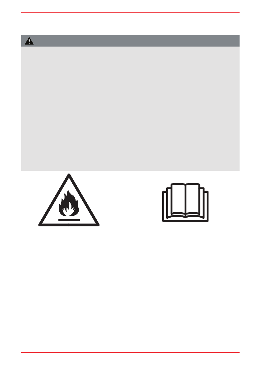
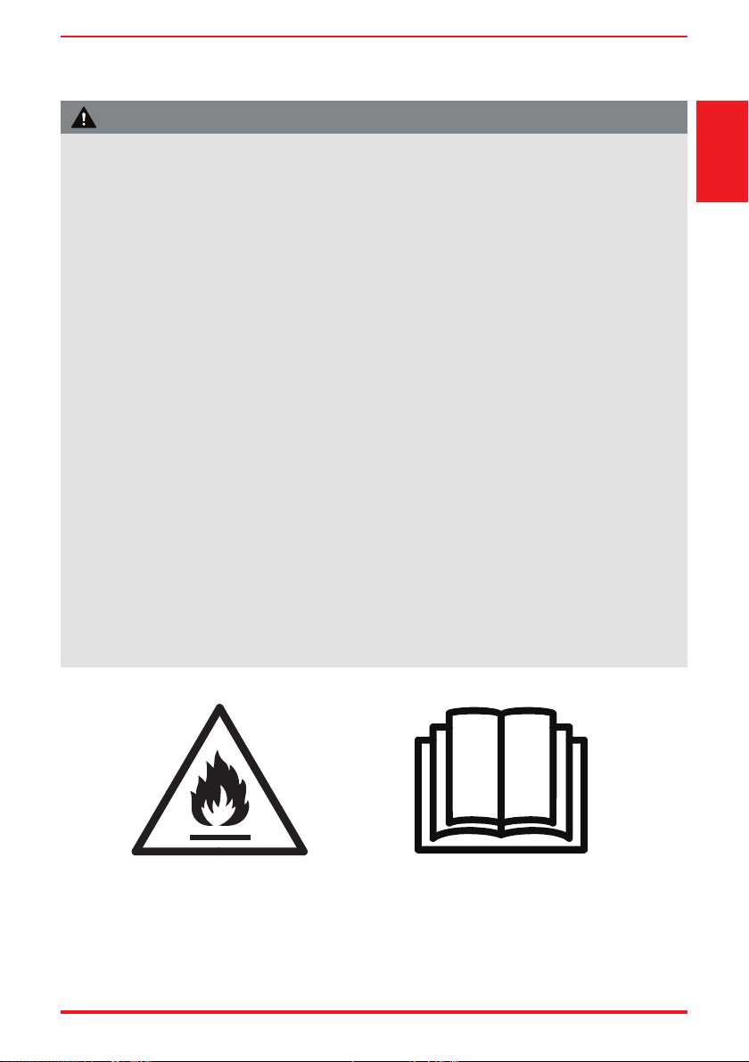
Caution: Risk of fire/
flammable materials
(Required for R32/R290 units only)
IMPORTANT NOTE: Read this manual
carefully before installing or operating
your new air conditioning unit. Make sure
to save this manual for future reference.
Page 6 User Manual
Safety
Precautions
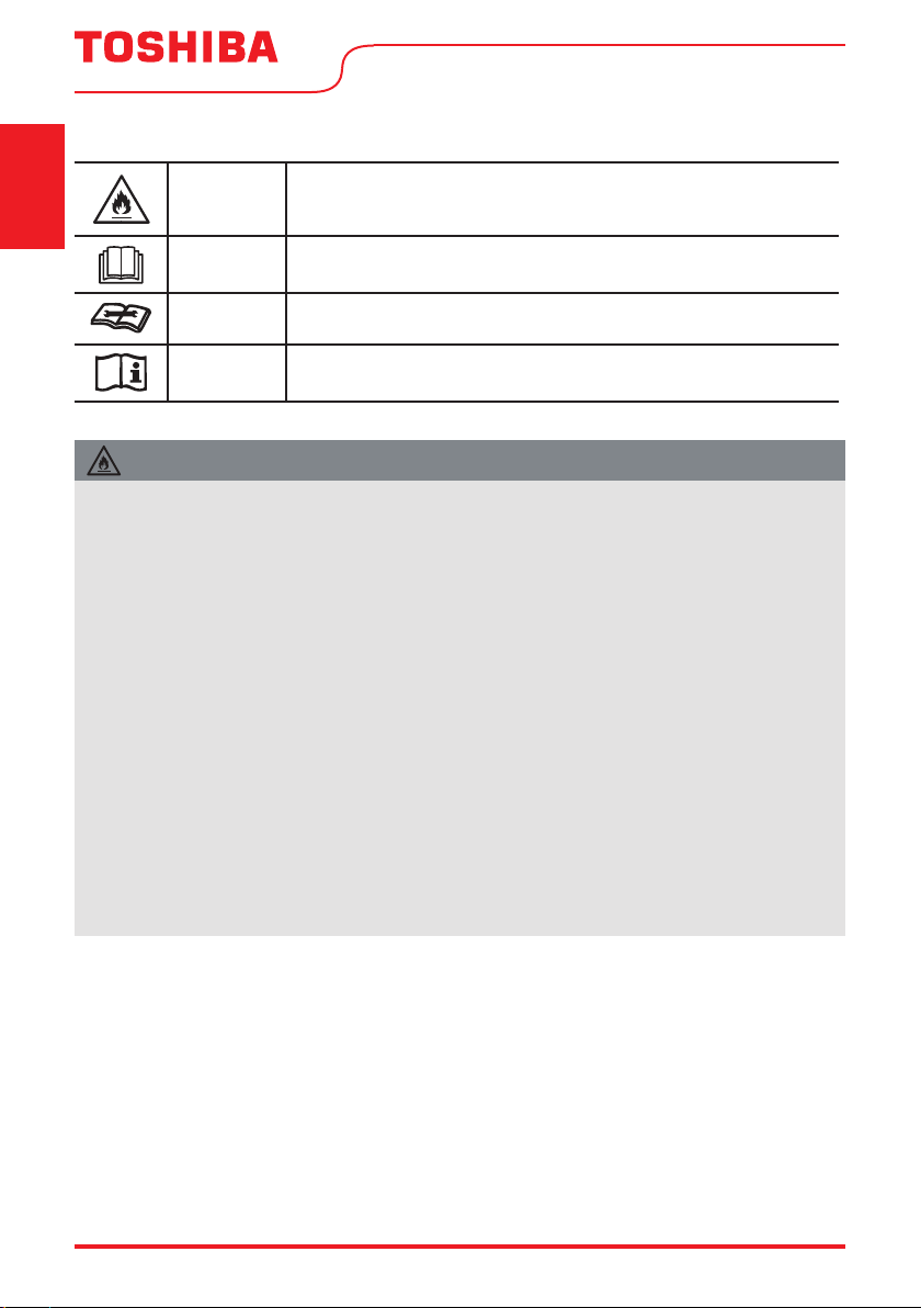
WARNING
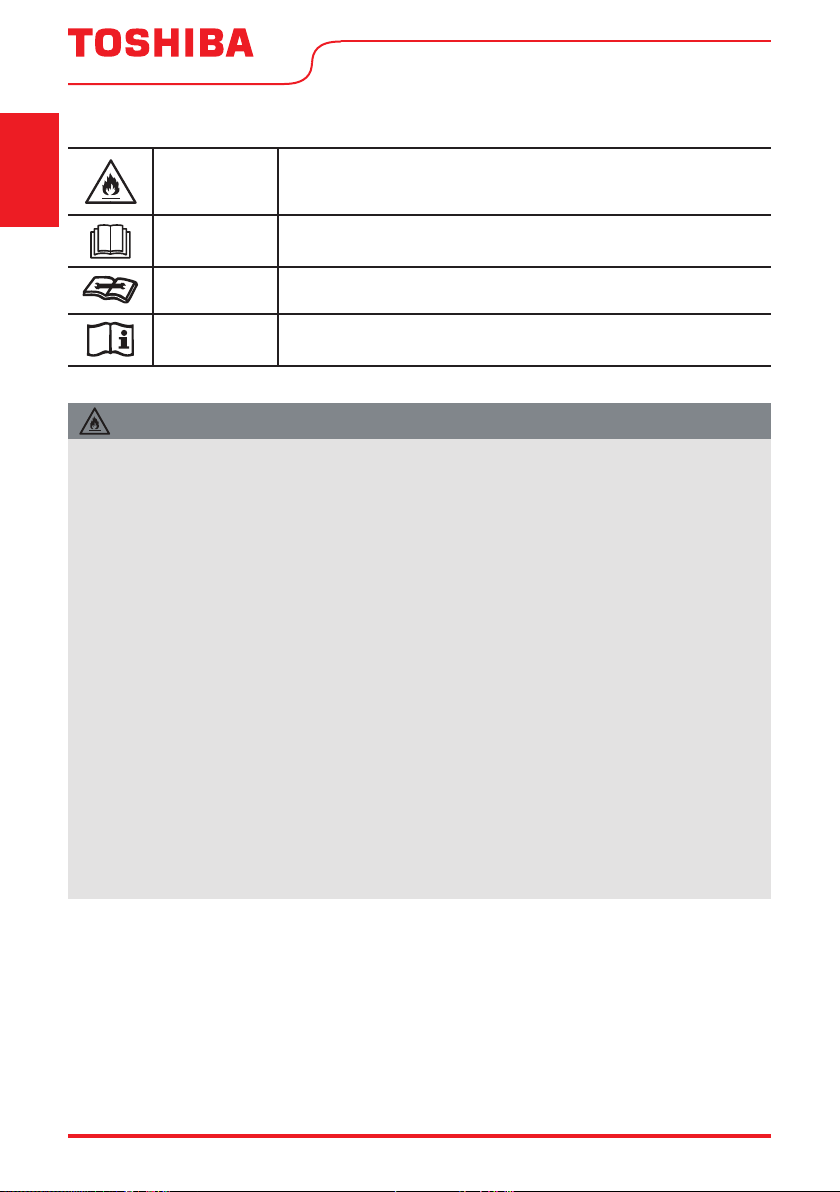
This symbol shows that this appliance used a ammable refrigerant.
If the refrigerant is leaked and exposed to an external ignition source,
there is a risk of re.
CAUTION
This symbol shows that the operation manual should be read carefully.
CAUTION
This symbol shows that a service personnel should be handling this
equipment with reference to the installation manual.
CAUTION
This symbol shows that information is available such as the operating
manual or installation manual.
EXPLANATION OF SYMBOLS DISPLAYED ON THE UNIT
• Do not try to accelerate the defrosting process or methods of cleaning that are not
recommended by the manufacturer.
• The appliance shall be stored in a room without a continuously operating ignition source (for
example, open ames or an operating gas appliance) or an ignition source (for example, an
operating electric heater) close to the appliance. The appliance shall also be stored in a room
without ignition sources.
• Do not pierce or burn.
• Be aware that the refrigerants may not contain an odor.
• Keep ventilation openings clear of obstruction.
• Unit is only to be serviced by a Toshiba authorized servicer, please call Customer Service at
1-855-204-5313 for support.
• Flammable refrigerant R32 is used within air conditioner. Please follow the instructions carefully
to handle, install, clean, and service the air conditioner to avoid damage or hazard. Do not
dispose of air conditioner in regular trash. Contact quali ed agency for proper disposal.
• No open re or devices that generate spark/arcing shall be around the air conditioner to avoid
causing ignition of the ammable refrigerant used. Please follow the instructions carefully to
store or maintain the air conditioner to prevent mechanical damage from occurring.
WARNING (for using R32 refrigerant only)
User Manual Page 7
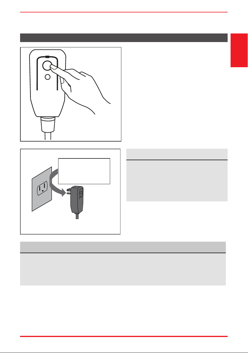
The power supply cord with this air conditioner
contains a current detection device designed
to reduce the risk of re.
In the event that the power supply cord is
damaged, it can not be repaired. It must be
replaced with a cord from the manufacturer.
Safety
Precautions
• Do not use this device to turn the unit on or o .
• Always make sure the RESET button is pushed in for correct operation.
• The power supply cord must be replaced if it fails to reset when either the TEST button is pushed,
or it can not be reset. Please contact Customer Service.
Grounding type wall receptacle
Do not, under any
circumstances, cut,
remove or bypass
the grounding prong.
Power supply cord with 3-prong grounding
plug and current detection device.
The power supply cord contains a current
measuring device that detects damage to the
power cord. Test your power supply cord as
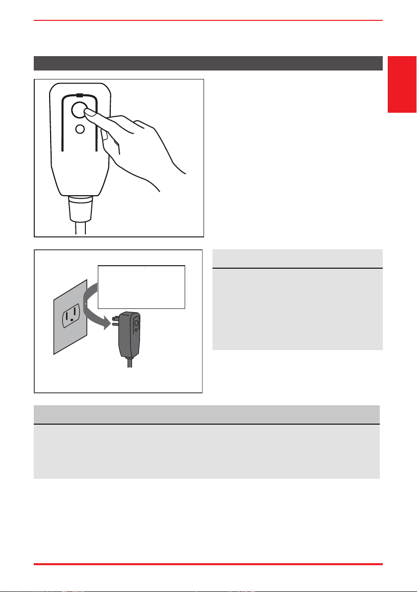
follows:
1. Plug in the air conditioner.
2. The power supply cord will have TWO
buttons on the plug head. Press the TEST
button. You will notice a click as the RESET
button pops out.
3. Press the RESET Button. You will notice a click
as the button engages.
4. The power supply cord is now supplying
electricity to the unit. (On some products this
is also indicated by a light on the plug head.)
RESET
TEST
Plug in & press RESET
Operation of Current Device
NOTICE
NOTICE
Page 8 User Manual
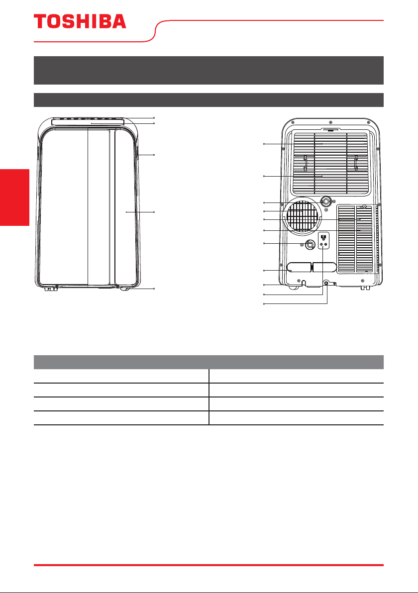
Preparation
Control panel
Handle
(both sides)
Outlet louver
(automatic swing)
Caster
Panel
raeRtnorF
Power plug storage
Power cord storage
Bottom tray
drain outlet
Power cord outlet
Drain outlet
(heat pump
models only)
Upper air filter
(behind the grille)
Upper air intake
Air outlet
Lower air filter
Lower air intake
Drain outlet
6&$/(
Unit Operating Temperature Range:
Mode Temperature Range
Cool 62°F ~ 95°F (17°C ~ 35°C)
Dry 55°F ~ 95°F (13°C ~ 35°C)
Heat (heat pump models only) 41°F ~ 86°F (5°C ~ 30°C)
Heat (electrical heat mode) ≤ 86°F (30°C)
OPERATING INSTRUCTIONS
Operating
Instructions
Exhaust Hose Installation:
The exhaust hose and adaptor must be installed or removed in accordance with the usage mode.
For COOL, HEAT (heat pump type) or AUTO mode, exhaust hose must be installed.
For FAN, DEHUMIDIFY or HEAT (electric heat type) mode, exhaust hose must be removed.
User Manual Page 9
Operating
Instructions
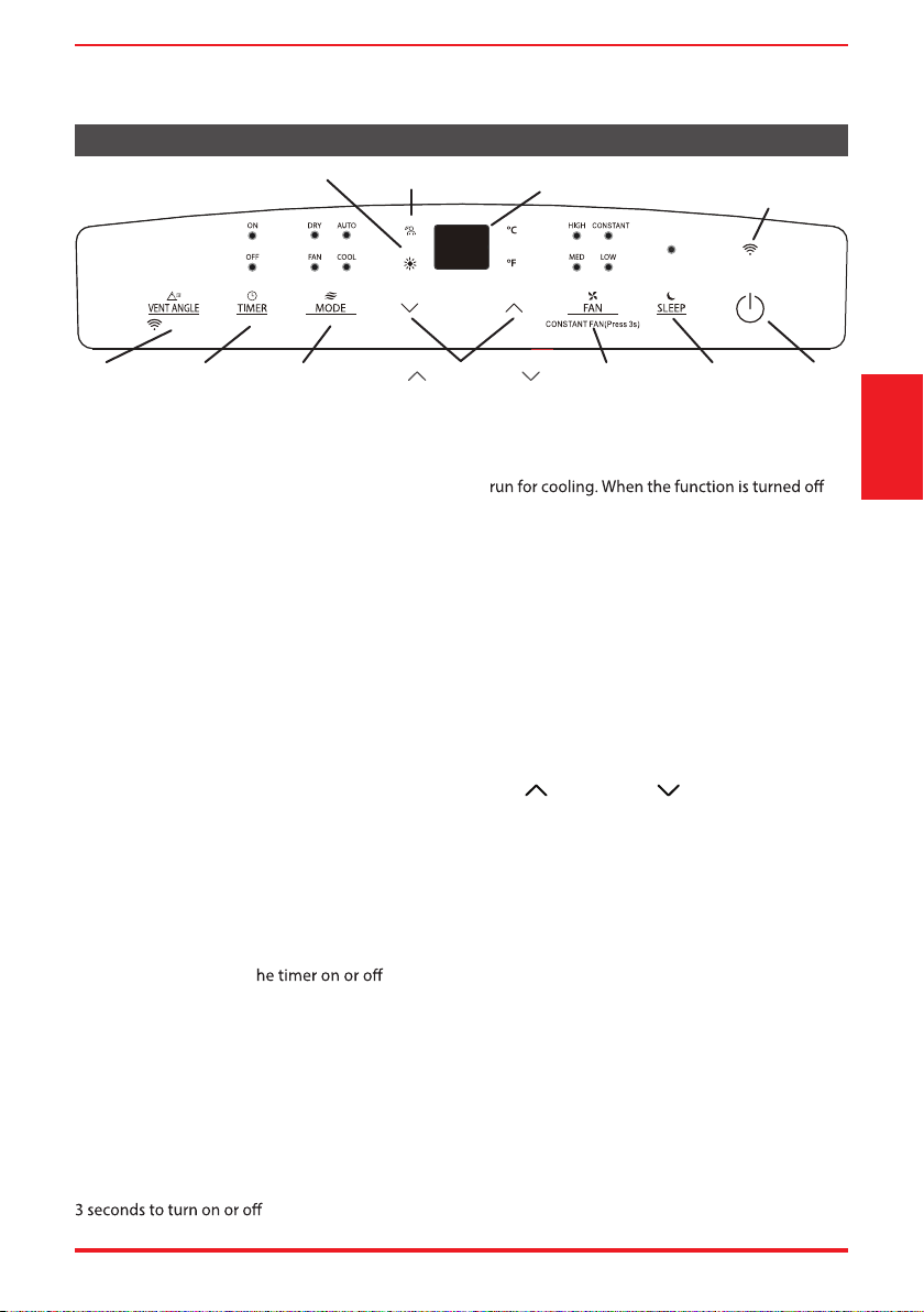
Control Panel Features
Swing Button
Used to initiate the Auto Swing feature. When the
operation is ON, pressing the SWING button can
stop the louver at the desired angle.
Connect Button (Smart models only)
Also used to initiate the wireless connection mode.
To initiate the wireless connection mode, power on
the air conditioner then press the SWING button
for 3 seconds. The LED DISPLAY will show ‘AP’ to
indicate the unit is in wireless connection mode.
Refer to the app connection instructions to nish
the connection process.
If the connection is successful, the unit will exit
wireless connection mode and illuminate the
wireless LED. If the connection fails, the unit will
exit wireless connection mode automatically after 8
minutes and the wireless LED does not illuminate.
Note: The wireless connection process must be
completed within 8 m
inutes after powering the air
conditioner on.
Timer button
Used to initiate the AUTO ON start time and AUTO
OFF stop time program. T light will
illuminate depending on the selected setting.
Fan button
Controls the fan speed. Press to control the fan speed in
four steps - LOW, MID, HIGH and AUTO. The selected fan
speed light (except AUTO) will illuminate. When AUTO is
selected, no lights will illuminate.
NOTE: Applicable to models with the Constant Fan
feature. In COOL or DRY mode, press the Fan button for
the constant fan function.
When the function is turned on, the constant fan
light will illuminate, identifying the fan continuous
,
the constant fan light will go out, identifying the
fan cycle run with compressor stop.
Mode button
Selects the desired operating mode. Each time
you press the button, a mode is selected in a
sequence that goes from AUTO, COOL, DRY,
FAN and HEAT (cooling only models excluded).
The mode light illuminates and indicates the
selected mode. To change between °F or °C,
simultaneously press and hold the Up and
Down buttons for 3 seconds.
Up ( ) and Down ( ) buttons
Used to increase/decrease temperature
settings in 1°F (or 2°F)/1°C increments in a
range of 62°F/17°C to 86°F/30°C or the TIMER
setting in a range of 0 ~ 24hrs.
To change between °F or °C, simultaneously
press and hold the Up and Down buttons for
3 seconds.
Power button
Power switch on/o.
Sleep button
Used to initiate the SLEEP operation.
LED display
Shows the set temperature in °F (Degrees
Fahrenheit) or °C (Degrees Celsius) and the
Auto-timer settings. While on DRY and FAN
modes, it shows the room temperature.
Timer
Button
Swing
Button
Power
Button
Sleep
Button
Fan
Button
Up (
) and Down ( )
Buttons
Mode
Button
LED WIRELESS (SMART
MODELS ONLY)
DisplayMyTemp function
Heat Mode Indicator Light
(only for heat model)
MyTemp
HEAT
3 seconds
Page 10 User Manual
Operating
Instructions
Operating Instructions
COOL operation
• Press the “MODE” button until the “COOL” indicator
light comes on.
• Press the ADJUST buttons Up (
) or Down ( ) to
select your desired room temperature. The temperature
can be set within a range of 62°F~86°F/17°C~30°C.
• Press the “FAN SPEED” button to choose the fan speed.
HEAT operation
(available on HEAT models only)
• Press the “MODE” button until the “ ” indicator
light comes on.
• Press the ADJUST buttons Up (
) or Down ( ) to
select your desired room temperature. The temperature
can be set within a range of 62°F~86°F/17°C~30°C.
• Press the “FAN SPEED” button to choose the fan
speed. For some models, the fan speed cannot be
adjusted while in HEAT mode.
DRY operation
• Press the “MODE” button until the “DRY” indicator
light comes on.
• While in this mode, you cannot select a fan speed or
adjust the temperature. The fan motor operates at
LOW speed.
• Keep windows and doors closed for the best
dehumidifying e ect.
AUTO operation
• When you set the air conditioner to AUTO mode, it
will automatically select cooling, heating (cooling
only models excluded), or fan only operation
depending on what temperature you have selected
and the current room temperature.
• The air conditioner will control room temperature
automatically according to the temperature point
set by you.
• Under AUTO mode, you cannot select the fan
speed.
FAN operation
• Press the “MODE” button until the ”FAN“
indicator light comes on.
• Press the “FAN SPEED” button to choose the fan
speed. The temperature cannot be adjusted.
• Do not connect the duct to a window.
TIMER: Auto Start/Stop Operation
• When the unit is on, pressing the Timer button
will initiate the Auto stop program. The TIMER
OFF indicator light illuminates. Press the Up
( ) or Down ( ) button to select the desired
time. Press the TIMER button again within 5
seconds. The Auto start program is initiated
and the TIMER ON indicator light illuminates.
Press the Up ( ) or Down ( ) button to select
the desired Auto start time.
• When the unit is o , press the Timer button to
initiate the Auto start program. Pressing it again
within ve seconds will initiate the Auto stop
program.
• Press or hold the Up (
) or Down ( )
button to change the Auto time by 0.5 hour
increments, up to 10 hours, then at 1 hour
increments up to 24 hours. The control will
count down the time remaining until start.
• The system will automatically revert back to
display the previous temperature setting if
there is no operation within 5 seconds.
• Turning the unit ON or OFF at any time or
adjusting the timer setting to 0.0 will cancel the
Auto Start/Stop timer program.
• Should a malfunction occur, the Auto Start/Stop
timed program will also be cancelled.
Shows Error codes and protection code:
E1 - Room temperature sensor error.
E2 - Evaporator temperature sensor error.
E3 - Condenser temperature sensor error (select models).
E4 - Display panel communication error.
P1 - Bottom tray is full - Connect the drain hose and
drain the collected water away. If protection code
repeats, call for service.
When one of the above malfunctions occurs,
turn o the unit and check for any obstructions.
Restart the Unit. If the malfunction persists, turn
o the unit and unplug the power cord. Contact
the manufacturer or its service agents or a
similar quali ed person for service.
NOTICE
User Manual Page 11
Operating
Instructions
SLEEP operation
Pressing this button will increase (during cooling operation) or
decrease (during heating operation, applicable models) 1°F/1°C after
30 minutes. The temperature will again increase (cooling) or decrease
(heating) by another 1°F/1°C after an additional 30 minutes. This new
temperature will be maintained for 7 hours before returning to the
originally selected temperature. This ends the Sleep mode and the
unit will continue to operate as originally programmed.
NOTICE
The SLEEP operation feature is
unavailable in FAN or DRY mode.
Other Features
MyTemp
This feature can ONLY be activated from the remote control. The remote control serves as a remote
thermostat allowing for the precise temperature control at its location which must be within 26 feet of the
air conditioner. To activate the MyTemp feature, point the remote control towards the unit and press the
MyTemp button. The remote’s display will show actual temperature at its location and must be within
26 feet of the air conditioner to work. The remote control will send this signal to the air conditioner every
3 minutes until the MyTemp button is pressed again. If the unit does not receive the MyTemp signal
during any 7 minute interval, the unit will exit the MyTemp mode.
NOTE: This feature is unavailabe under FAN or DRY mode.
AUTO-RESTART
unexpectedly due to a power outage, it will restart with the previously set function
automatically when the power resumes.
WAIT 3 MINUTES BEFORE RESUMING OPERATION
After the unit has stopped, it cannot be restarted until 3 minutes time has elapsed. This is to protect the
unit. Operation will automatically resume after 3 minutes.
AIRFLOW DIRECTION ADJUSTMENT
The louver can be adjusted automatically using the SWING button.
• When the Power is ON, the louver opens fully.
• Press the SWING button on the panel or remote controller to initiate the Auto Swing feature. The louver
will swing up and down automatically.
• Please do not adjust the louver manually.
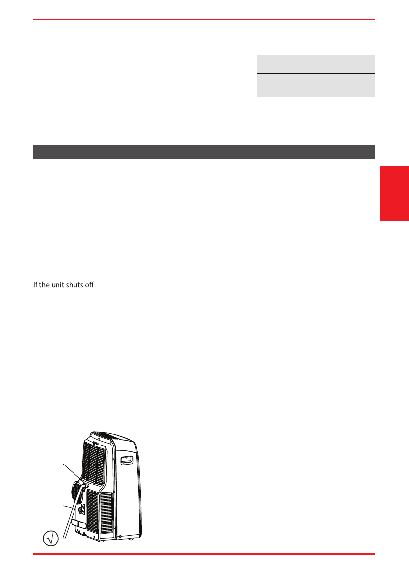
WATER DRAINAGE
• During Dry modes, remove the upper drain plug from the
back of the unit and install the drain connector (5/8” universal
female mender) with 3/4” hose (locally purchased).
For models without drain connector, just attach the drain hose
to the hole. Place the end of the hose directly in the drain area
you’re using.
Remove
the upper
drain plug
Continuous
drain hose
Page 12 User Manual
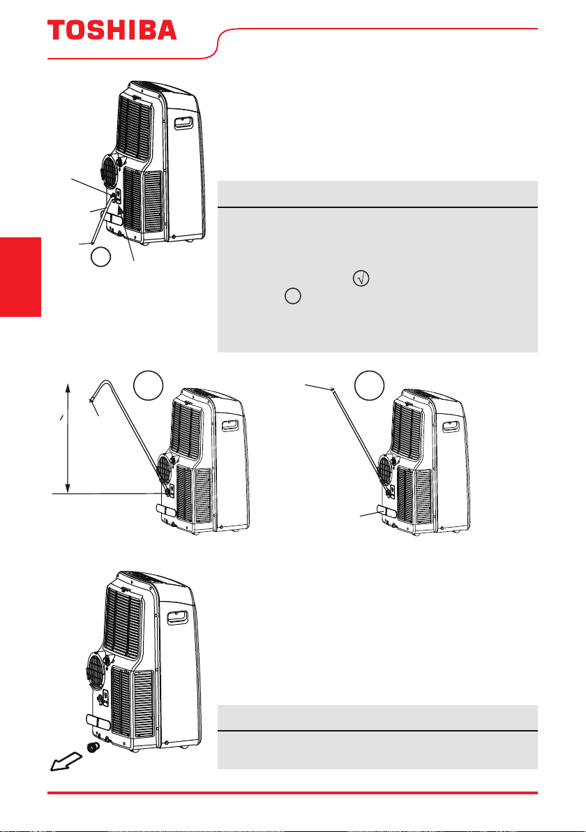
WATER DRAINAGE cont.
• For Heat Pump models, remove the middle drain plug from the
back of the unit and install the drain connector (5/8” universal
female adapter) with a 3/4“ hose (not included). For models
without the drain connector, attach the drain hose to the
connector. Place the end of the hose in the drain area you’re using.
Operating
Instructions
• When the water level of the bottom tray reaches a
predetermined level, the unit beeps 8 times. The digital
display shows “P1.” At this time the air conditioning/
dehumidi cation process will immediately stop. However, the
fan motor will continue to operate (this is normal). Carefully
move the unit to a drain location, remove the bottom drain
plug and let the water drain away. Reinstall the bottom drain
plug and restart the machine until the “P1” symbol disappears.
If the error repeats, call for service.
NOTICE
Be sure to reinstall the bottom drain plug rmly to prevent
leakage before using the unit.
NOTICE
In Heat Pump mode, the drain hose can be elevated up to 6ft (1.8m).
Direct the hose toward the drain, making sure that there are no
kinks that will re strict water ow. Place the end of the hose into the
drain and make sure the end of the hose is directed downward
manufacturer. See Figs with ).
Figures with
X
are installation not recommended by the
manufacturer. When the continuous drain hose is not used,
ensure that the corresponding drain plug and knob are installed
rmly to prevent leaks.
¥
Drain hose
adaptor
Continuous
drain hose
Remove the
middle drain
plug
Units with
heat pump
model only
X
Drain hose
adaptor
Press the power
cord buckle into
the rear cover.
Drain
hose
adaptor
¥
Delivery lift < 6ft
Units with heat pump model only
User Manual Page 13
INSTALLATION INSTRUCTIONS
Installation
Instructions
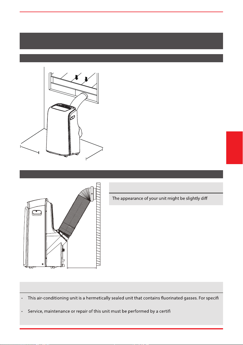
Choosing the Right Location
Recommended Installation
Your installation location should meet the following
requirements:
• Make sure that you install your unit on an even
surface to minimize noise and vibration.
• The unit must be installed near a grounded plug,
and the Collection Tray Drain (found on the back of
the unit) must be accessible.
• The unit should be located at least 19.7” (50cm)
from the nearest wall to ensure proper air
conditioning.
• DO NOT cover the Intakes, Outlets or Remote Signal
Receptor of the unit, as this could cause damage to
the unit.
NOTICE About Fluorinated Gasses
c
information on the type of gas and the amount, please refer to the relevant label on the unit itself.
ed technician.
• Product recycling must be done according to local regulations.
NOTICE
erent.
50cm
19.7inch
50 cm
19.7 inch
50 cm
19.7 inch
Page 14 User Manual
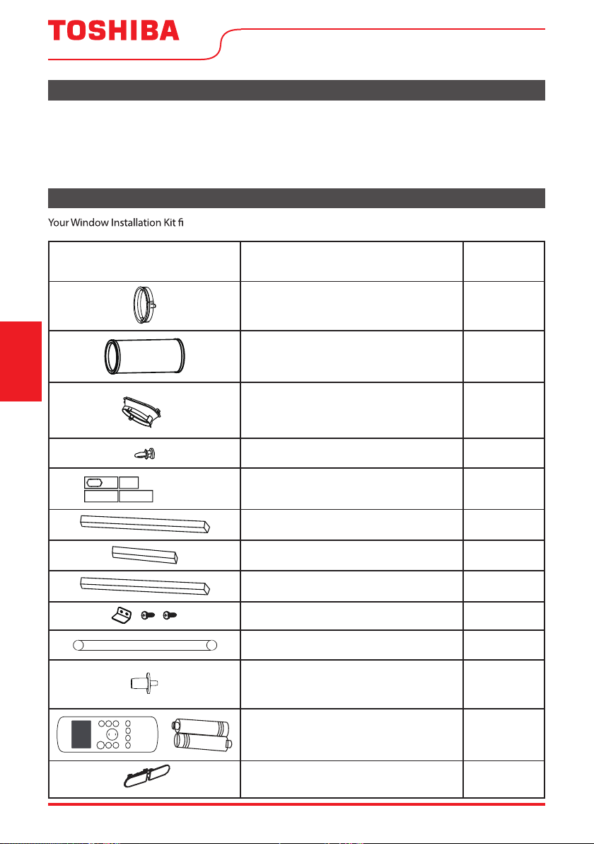
Accessories
ts windows 19.4’’-62.2’’ (49.3-158.1 cm).
noitpircseDtraP
Unit adaptor
Air exhaust passage
Window Sliders
Exhaust hose
Bolt
Foam seal A (adhesive)
Foam seal B (adhesive)
Foam seal C (Non-adhesive)
Security bracket and 2 screws
Drain hose
Drain hose adaptor
(For heat pump mode only)
Remote controller and battery
(For remote control models only)
1 pc
1 pc
1 pc
4 pc
1 pc
1 pc
2 pc
1 set
1 set
Quantity
1 pc
Power Cord Buckle
Tools Needed
• Phillips screwdriver
• Tape measure or ruler
• Knife or scissors
• Saw (optional, to shorten window adaptor for narrow windows).
Installation
Instructions
4 pc
2 pc
3 pc
User Manual Page 15
Installation
Instructions
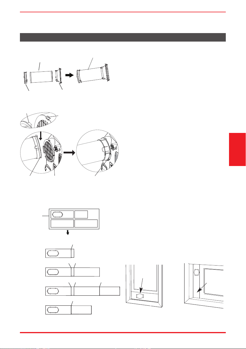
Window Installation Kit
1: Preparing the exhaust hose assembly
Press the exhaust hose into the Air exhaust
passanger and unit adaptor, clamp automatically
by elastic buckles of the adaptors.
2: Install the exhaust hose assembly to the
unit
Insert the unit adapter side of the exhaust hose
assembly into the groove of the air outlet on
the back of the unit. Align the hook of the unit
adapter with the seat on the air outlet and slide
the assembly down until seated.
3: Preparing the adjustable window slider
1. Depending on the size of your window,
adjust the size of the window slider.
2. If the length of the window requires two or
more window sliders, use the bolt to fasten
the window sliders once they are adjusted
to the proper length.
Exhaust hose
assembly
Exhaust hose
Unit adaptor
Air exhaust
passage
Hook
Hole Seat
Lower
groove
Adaptor
Make sure the adaptor
is inserted into the
lower groove of the
air outlet.
Hung Window Sliding Window
Windows Type
Window
slider A
Window
slider A
1+2:
Bolt
1+2+3:
Bolt
Bolt
1+2+3+4:
Bolt
BoltBolt
1+4:
Bolt
Window
Sliders
After assembly
Before assembly
Page 16 User Manual
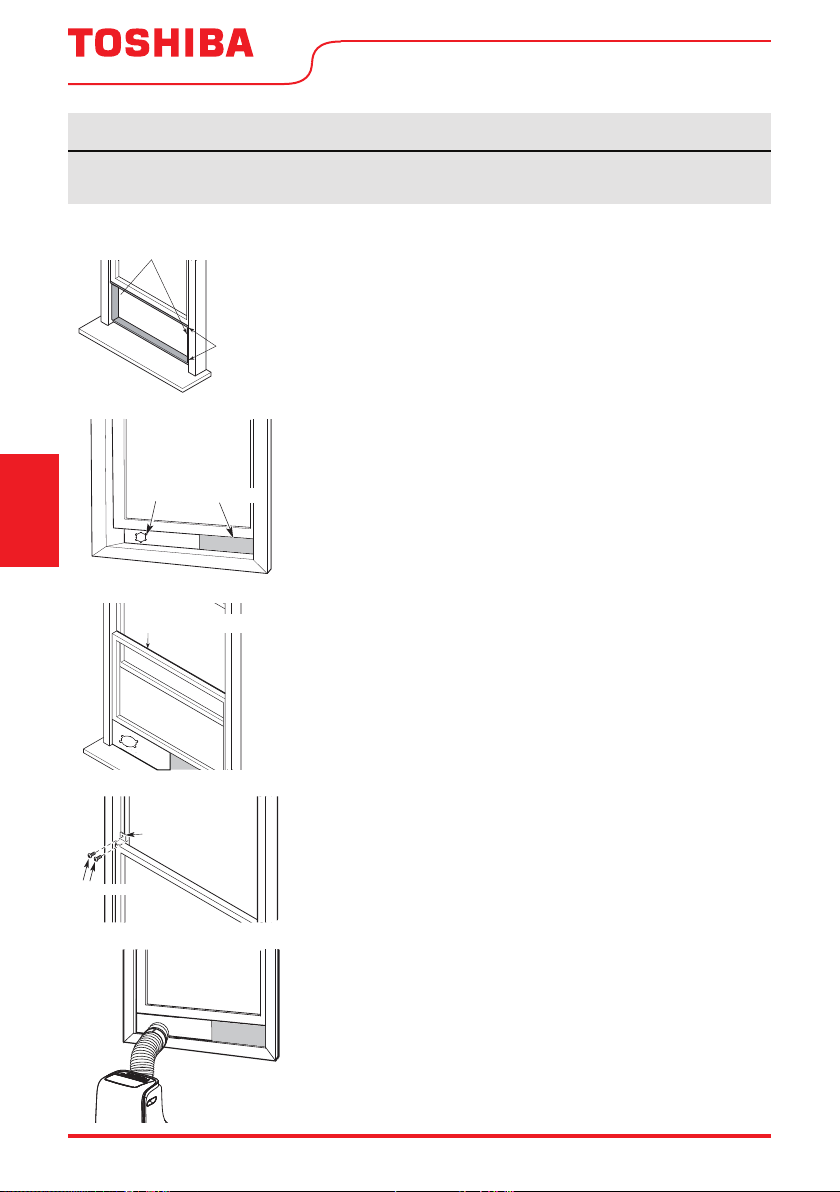
Type 1: Hung window installation
1. Cut the adhesive foam seal A and B strips to the proper lengths,
and attach them to the window sash and frame as shown.
2. Insert the window slider assembly into the window opening.
3. Cut the non-adhesive foam seal C strip to match the width of
the window. Insert the seal between the glass and the window
frame to prevent air and insects from getting into the room.
4. If desired, install the security bracket with 2 screws as shown.
5. Insert the window slider adaptor into the hole of the window
slider.
NOTICE
Once the Exhaust Hose assembly and Adjustable Window Slider are prepared, choose from one of
the following two installation methods.
Foam seal B
(Adhesive type-shorter)
Foam
seal A
(Adhesive
type)
Window
slider A
Window
slider B
(if required)
Foam seal C
(Non-adhesive type)
Security Bracket
2 Screws
Installation
Instructions
User Manual Page 17
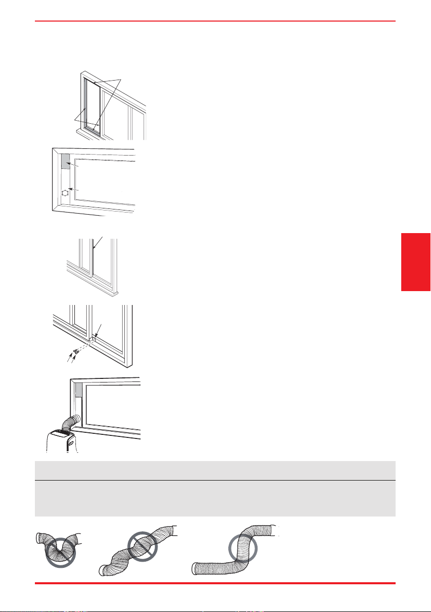
Type 2: Sliding window installation
1. Cut the adhesive foam seal A and B strips to the proper lengths,
and attach them to the window sash and frame as shown.
2. Insert the window slider assembly into the window opening.
3. Cut the non-adhesive foam seal C strip to match the window
height. Insert the foam seal between the glass and the window
frame to prevent air and insects from getting into the room.
4. If desired, install the security bracket with 2 screws as shown.
5. Insert the window slider adaptor into the hole of the window
slider.
Foam seal B
(Adhesive
type-shorter)
Foam seal A
(Adhesive
type)
Foam seal C
(Non-adhesive type)
2 Screws
Security
Bracket
NOTICE
To ensure proper function, DO NOT overextend or bend the hose. Make sure that there are
no objects within 20in (~500mm) of the exhaust hose. All illustrations in this manual are for
explanation purposes only, your air conditioner may be slightly dierent than shown.
Window slider A
Window slider B
(if required)
Installation
Instructions
Page 18 User Manual
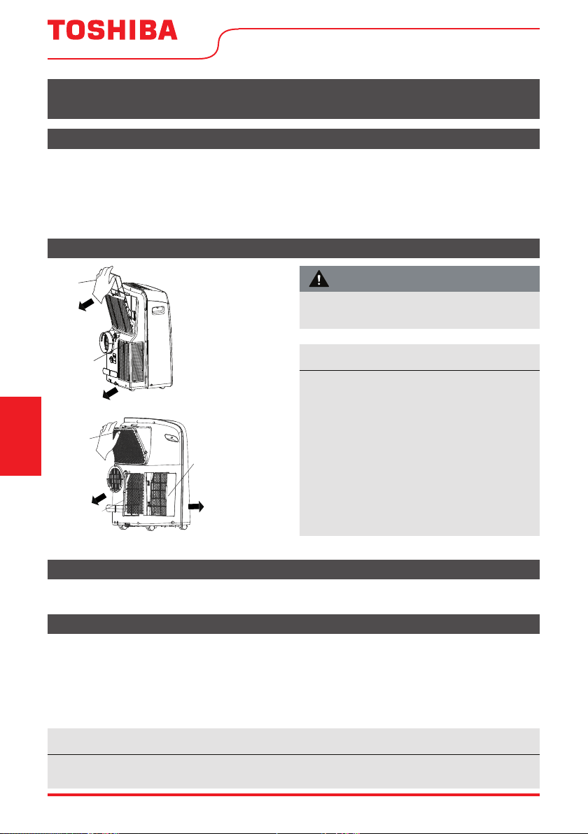
Air Filter Cleaning
Unit Cleaning
Store the Unit When Not in Use
Safety Precautions
CARE AND CLEANING
Care and Cleaning
• Always unplug the unit before cleaning or servicing.
• DO NOT use flammable liquids or chemicals to clean the unit.
• DO NOT wash the unit under running water. Doing so causes electrical danger.
• DO NOT operate the machine if the power supply was damaged during cleaning. A damaged
power cord must be replaced with a new cord from the manufacturer.
Clean the unit using a damp, lint-free cloth and mild detergent. Dry the unit with a dry, lint-free cloth.
• Drain the unit’s water collection tray according to the instructions in the following section.
• Run the unit on FAN mode for 12 hours in a warm room to dry it and prevent mold.
• Turn o the unit and unplug it.
• Clean the air filter according to the instructions in the previous section. Reinstall the clean, dry
filter before storing.
• Remove the batteries from the remote control.
Remove the
air filter
Upper
filter
(take out)
Take the
lower filter
out.
lower filter A
Upper air filter
(combined
filter with grill,
take out)
lower filter B
(take out)
(Press the grill
down slightly
and pull the
lower filter A out
at the same time)
Only for MODEL
RAC-PD1414CWRU
Only for MODEL
RAC-PD0812CRRU,
RAC-PD1013CWRU and
RAC-PD1213CWRU
NOTICE
Be sure to store the unit in a cool, dark place. Exposure to direct sunlight or extreme heat can
shorten the lifespan of the unit.
Maintenance Tips
• Be sure to clean the air filter every 2 weeks
for optimal performance.
• The water collection tray should be drained
immediately after P1 error occurs, and
before storage to prevent mold.
• In households with animals, you will have to
periodically wipe down the grill to prevent
blocked air ow due to animal hair.
• RAC-PD0812CRRU, RAC-PD1013CWRU and
RAC-PD1213CWRU’s air lters are built into
and part of the rear grill.
DO NOT operate the unit without lter because
dirt and lint will clog it and reduce performance.
CAUTION
User Manual Page 19
TROUBLESHOOTING TIPS
Troubleshooting
Tips
Before calling service, review this list. It may save you time and expense. This list includes common
occurences that are not the result of defective workmanship or materials of this appliances.
NOTICE
Do not add extension to the exhaust hose(s)!
Problem Solution
Unit does not turn
on when pressing
ON/OFF button
Displays P1 Error Code and means the water collection tray is full. Turn o the
unit, drain the water from the water collection tray, and restart the unit.
If room temperature is lower than the set temperature in COOL mode, reset
the temperature.
Unit does not cool
well
The air lter is blocked with dust or animal hair. Turn o the unit and clean the
lter according to the instructions.
Exhaust hose is not connected or is blocked. Turn o the unit, disconnect the
hose, check for blockage and reconnect the hose.
Temperature setting is too high; decrease the set temperature.
Make sure all windows and doors are closed.
The room area could be too large; doublecheck the cooling area.
Check the room for possible heat sources and remove them if possible.
The unit is noisy and/
or vibrates too much
The oor is not level. Place the unit on a at, level surface.
The air lter is blocked with dust or animal hair. Turn o the unit and clean the
lter according to the instructions.
The unit makes a
gurgling sound
This sound is caused by the refrigerant ow inside the unit and is normal.
Uni
t will not connect
to Wireless or App
does not work
(some models)
For additional support and troubleshooting tips, follow the link in the QR code:
Page 20 User Manual
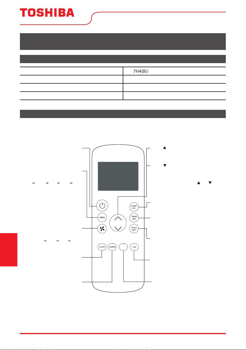
Remote Control Specifi cations
Function Buttons
REMOTE CONTROL AND APP INSTRUCTIONS
Before you begin using your new air conditioner, make sure to familiarize yourself with its remote
control. The following is a brief introduction to the remote control itself. For instructions on how to
operate your air conditioner, refer to the Operating Instructions section of this manual.
5GRledoM BGEFU1
Rated voltage 3.0V (Dry batteries R03/LR03x2)
Signal receiving range 26 ft. (approx. 8 m)
Environment 23°F ~ 140°F (-5°C ~ 60°C)
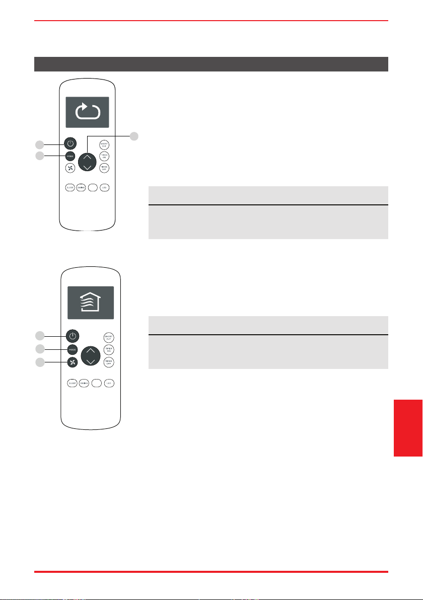
MyTemp
Turns the MyTemp feature on and off.
SHORT CUT
Sets and activates your favorite pre-settings.
Turns the unit on or off.
TEMP
Increases temperature in 1° increments.
Max. temperature is 86°F (30°C).
TIMER ON
Sets timer to turn unit on (see Basic
Functions for instructions)
TIMER OFF
LED
Turns the AC’s LED display on and off.
SWING
Starts and stops
louver movement.
SLEEP
Saves energy during
sleeping hours.
TEMP
Decreases temperature in 1° increments.
Min. temperature is 62°F (17°C).
NOTE: Pressing and holding and buttons
together for 3 seconds will alternate the
temperature display between the °F & °C scale.
Selects fan speeds in the
following order:
AUTO LOW MED HIGH
MODE
Scrolls through operation modes
as follows:
AUTO COOL DRY HEAT FAN
NOTE:
Please do not select HEAT mode
if the machine you purchased is
cool-only type. Heat mode is not
supported by cool-only models.
ON/OFF
FAN SPEED
MyTemp
Sets timer to turn unit off (see Basic
Functions for instructions)
Remote Control and
App Instructions
User Manual Page 21
Handling the Remote Control
NOT SURE WHAT A FUNCTION DOES?
Refer to the Operating Instructions section of this manual for a detailed description of the functions
available using the remote.
NOTICE
Button designs on your unit may differ slightly from the example shown.
If the unit does not have a specic function, using that function’s button on the remote control
will have no effect.
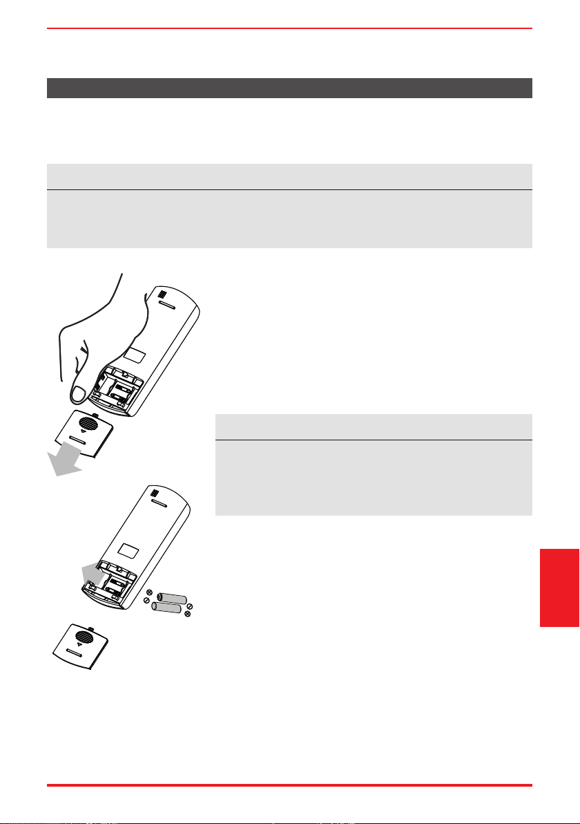
INSERTING AND REPLACING BATTERIES
Your air conditioning unit comes with two AAA batteries. Insert the
batteries in the remote control before use.
1. Slide the back cover of the remote control downward, exposing
the battery compartment.
2. Insert the batteries, paying attention to align the (+) and (-) ends
of the batteries with the symbols inside the battery compartment.
3. Slide the battery cover back into place.
BATTERY DISPOSAL
Ensure used batteries are disposed of properly.
TIPS FOR USING REMOTE CONTROL
• The remote control must be used within 26 feet / 8 meters of
the unit.
• The unit will beep when it receives a signal from the remote.
Curtains, other materials and direct sunlight can interfere with
the IR signal receiver.
• In order to properly transmit a command, the ON/OFF indicator
must be illuminated on the remote’s display. (See the Remote
LED Screen Indicators section for more information.)
BATTERY NOTES
For optimum product performance:
• Do not mix old and new batteries, or batteries of di erent types.
• Do not leave batteries in the remote control if you don’t plan
on using the device for more than 2 months.
Remote Control and
App Instructions
Page 22 User Manual
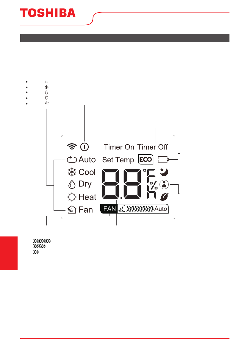
AUTO
COOL
DRY
HEAT
FAN
Transmission Indicator
Lights up when remote sends signal to unit
MODE display
Displays the current
mode, including:
TIMER ON display
Displays when
TIMER ON is set
TIMER OFF display
Displays when
TIMER OFF is set
Battery display
Low battery detection
SLEEP display
Displays when SLEEP
function is activated
FAN SPEED display
Displays selected FAN SPEED:
HIGH
MED
LOW
This display is blank when
set to AUTO speed.
Temperature/Timer display
Displays the set temperature by default, or timer setting
when using TIMER ON/OFF functions:
- Temperature range: 62°F-86°F (17°C-30°C)
- Timer setting range: 0-24 hours
This display is blank when operating in FAN mode.
ON/OFF display
Appears when the remote is enabled and can send a signal to the unit.
If you would like to turn the remote off without affecting the unit, point
the remote away from the unit and press the ON/OFF button.
To turn the remote on, point the remote away from the unit and press
the ON/OFF button.
The unit will not receive commands from the remote if this indicator is
not illuminated.
MyTemp display
Indicates that the
MyTemp
function is on
Remote LED Screen Indicators
Remote Control and
App Instructions
User Manual Page 23
Basic Functions
SETTING THE DESIRED TEMPERATURE
The operating temperature range for this unit is 62°F-86°F (17-30°C).
You can increase or decrease the set temperature in 1°F or 1°C increments.
Changing the Mode
1. To change the operating mode, press the MODE button until the
desired mode appears on the remote’s display.
2. Set the desired temperature.
NOTICE
If the unit does not change when the button is pressed, check that
the ON/OFF indicator is illuminated. If it is not, point the remote at
the unit and press the ON/OFF button.
NOTICE
If the unit does not change when the button is pressed, check that
the ON/OFF indicator is illuminated. If it is not, point the remote at
the unit and press the ON/OFF button.
Changing the Fan Speed
To change the fan speed, press the FAN button until the desired fan
speed appears on the remote’s display.
Remote Control and
App Instructions
1
3
2
MyTemp
1
2
3
MyTemp
Page 24 User Manual
Timer Functions
NOTICE
This number indicates the amount of time after the current time
after which you want the unit to turn on.
For example, if you set TIMER ON for 2 hours, “2.0h“ will appear on
the screen, and the unit will turn on after 2 hours.
Your air conditioning unit has two timer-related functions:
TIMER ON - sets the amount of time after which the unit will
automatically turn on.
TIMER OFF - sets the amount of time after which the unit will
automatically turn off.
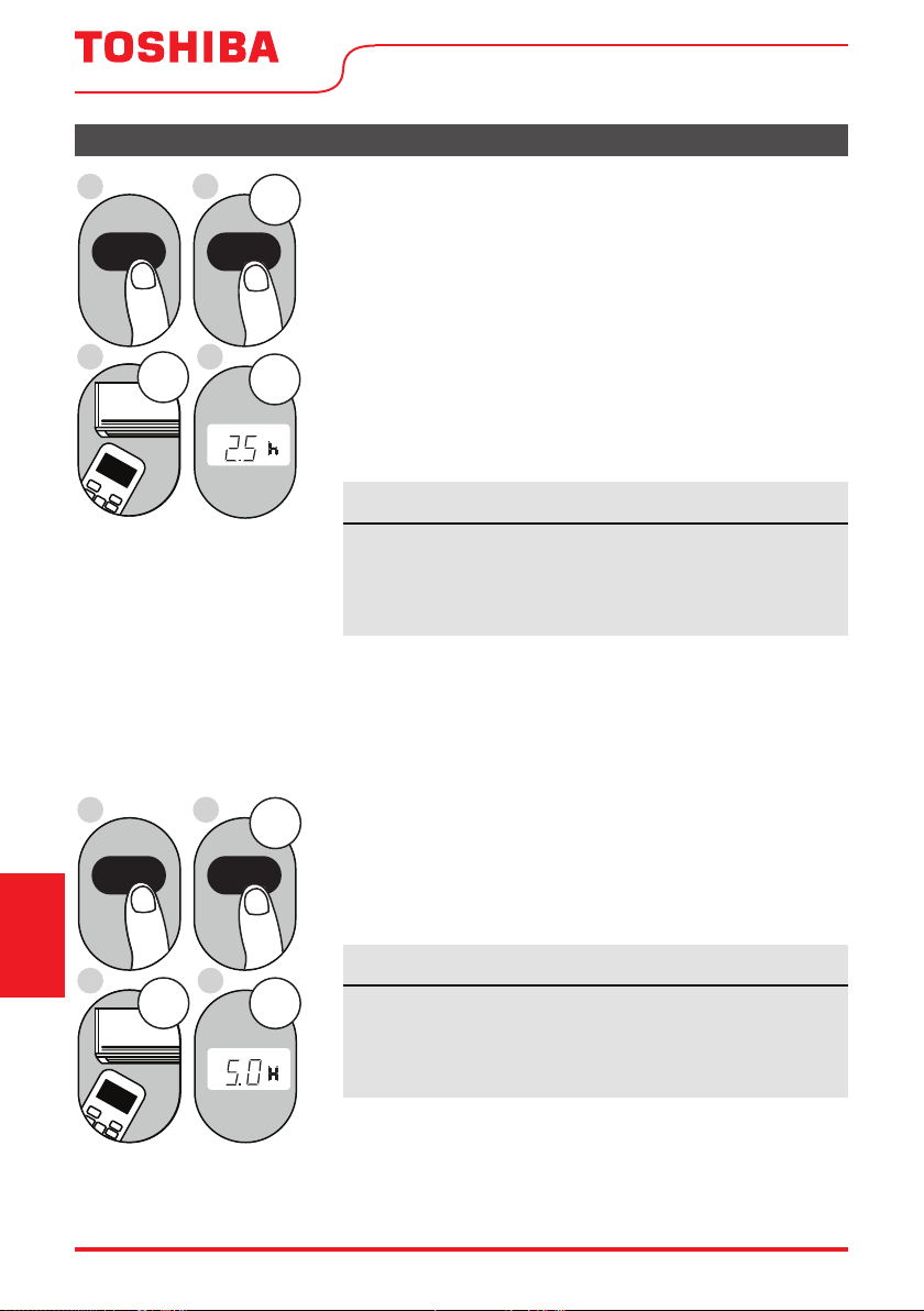
TIMER ON function
The TIMER ON function allows you to set a period of time after
which the unit will automatically turn on, such as when you come
home from work.
1. Press the TIMER ON button. By default, the last time period that
you set and an “
h” (indicating hours) will appear on the display.
2s e c
ON/OFF
MODE
F
AN
SHORT
CUT
TIMER ON
TIMER OF
F
TEMP
S
L
E
EP
1sec
x5
1
3
2
4
TIMER ON TIMER ON
Example: Setting unit to turn
on after 2.5 hours.
2. Press the TIMER ON button repeatedly to set the time that you
want the unit to turn on.
3. Wait 2 seconds, then the TIMER ON function will be activated.
The digital display on your remote control will then return to the
temperature display.
2sec
x10
ON/OFF
MODE
F
AN
SHORT
CUT
TIMER ON
TIMER OF
F
TEMP
S
LEEP
1sec
1
3
2
4
TIMER OFF
TIMER OFF
Example: Setting unit to turn
o after 5 hours.
TIMER OFF function
The TIMER OFF function allows you to set a period of time after
which the unit will automatically turn o , such as when you wake up.
1. Press the TIMER OFF button. By default, the last time period that
you set and an “h” (indicating hours) will appear on the display.
2. Press the TIMER OFF button repeatedly to set the time that you
want the unit to turn o .
This number indicates the amount of time after the current time
after which you want the unit to turn o .
For example, if you set TIMER OFF for 2 hours, “2.0h“ will
appear on the screen, and the unit will turn off after 2 hours.
NOTICE
Remote Control and
App Instructions
User Manual Page 25
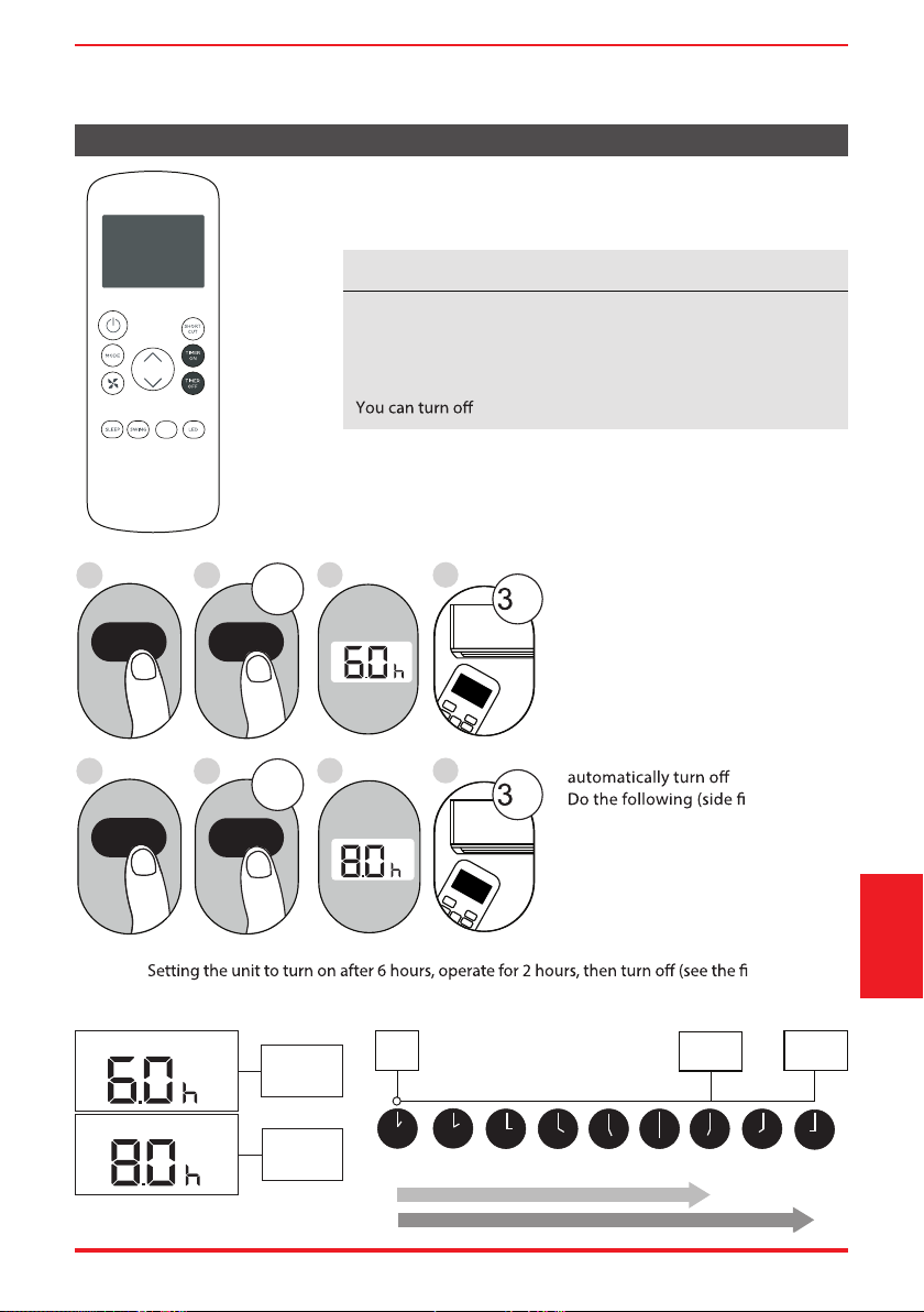
Timer Functions (cont.)
3. Wait 2 seconds, then the TIMER OFF function will be activated.
The digital display on your remote control will then return to
the temperature display.
NOTICE
When setting the TIMER ON or TIMER OFF functions, up to 10
hours, the time will increase in 30 minute increments with each
press. After 10 hours and up to 24, it will increase in 1 hour
increments. The timer will revert to zero after 24 hours.
either function by setting the timer to “0.0h“.
ON/OFF
MODE
SHORT
CUT
TIMER ON
TEMP
sec
4
ON/OFF
MODE
SHORT
CUT
TIMER ON
TEMP
sec
8
1
TIMER ON
X12
2
TIMER ON
5
TIMER OFF
X16
6
TIMER OFF
3
7
Setting both TIMER ON and
TIMER OFF at the same time
Keep in mind that the time periods
you set for both functions refer to
hours after the current time. For
example, say that the current time
is 1:00 PM, and you want the unit to
turn on automatically at 7:00 PM and
want it to operate for 2 hours, then
at 9:00 PM.
gure):
Example:
gure below).
Timer On
Timer O
Timer is set
To turn ON
6 hours from
current time
Timer is set
To turn OFF
8 hours from
current time
Current
Time 1PM
2PM 3PM
4PM 5PM
6PM 7PM 8PM 9PM
Unit turns
ON
Unit turns
OFF
6 hours later
8 hours later
Timer
Starts
Your remote display
Remote Control and
App Instructions
T i m e r o n
Continue
to press
TIMER ON
or
TIMER OFF
until desired
time is
reached.
MyTemp
Page 26 User Manual
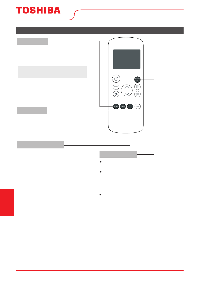
How to Use the Advanced Functions
SHORTCUT Function
SWING Function
MyTemp function
SLEEP Function
The SLEEP function is used to decrease
energy use while you sleep (and don’t need
the same temperature settings to stay
comfortable).
Used t
The MyTemp function enables the remote
control to measure the temperature at its
current location.
When using AUTO, COOL, or HEAT functions,
measuring ambient temperature from the
remote control (instead of from the indoor
unit itself) will enable the air conditioner to
optimize the temperature around you and
ensure maximum comfort.
1. Press at its button to activate function.
The remote control will send temperature
signal to the unit every three minutes.
2. Press at its button again to turn off
this function.
o stop or start louver movement and set the
desired up/down air flow direction. The louver
angle changes in 6 degree increments with each
press (not all models). By pressing for more than 2
seconds, the louver auto swing feature is activated.
Used to restore the current settings or resume
previous settings.
Push this button when remote controller is on,
the system will automatically revert back to the
previous settings including operating mode,
setting temperature, fan speed level and sleep
feature (if activated).
By pressing for more than 2 seconds, the
system will automatically store the current
operation settings including operating mode,
setting temperature, fan speed level and sleep
feature (if activated).
Note:
The SLEEP function is not
available in FAN or DRY mode.
MyTemp
Remote Control and
App Instructions
User Manual Page 27
Remote Control and
App Instructions
We hereby declare that this AC is in compliance with the essential requirements and other relevant
provisions of Directive 1999/5/EC.
1. Supports operating systems: iOS 7+ or Android 4+.
2. In the event of a OS update, there may be a delay between the update of the OS and a related
software update during which your OS may or may not be supported until a new version is
c mobile phone or problems in your network may prevent the system
from working and Toshiba will not be responsible for any problems that could be caused by
incompatibility or network issues.
3. This Smart AC only supports WPA-PSK/WPA2-PSK (recommended) encryption.
Please check the Toshiba Lifestyle website, www.toshiba-lifestyle.com, for updated information.
DECLARATION OF CONFORMITY
SPECIFICATION OF WIRELESS MODULE
PRECAUTIONS
Model: US-SK105 Dimensions: 41 x 24 x 5 (mm)
Standard: IEEE 802.11 b/g/n Operation Temperature: 0°C ~ 45°C / 32°F ~ 113°F.
Antenna Type: Printed PCB Antenna Operation Humidity: 10% ~ 85%
Frequency band: 2400-2483.5MHz Power Input: DC 5V/300 mA
Maximum Transmitted Power: <20 dBm Max
This device complies with part 15 of the FCC Rules. Operation is subject to the following two
conditions: (1) This device may not cause harmful interference, and (2) this device must accept
any interference received, including interference that may cause undesired operation.
Note: This equipment has been tested and found to comply with the limits for a Class B digital
device, pursuant to part 15 of the FCC Rules. These limits are designed to provide reasonable
protection against harmful interference in a residential installation. This equipment generates,
uses and can radiate radio frequency energy and, if not installed and used in accordance with
the instructions, may cause harmful interference to radio communications. However, there is
no guarantee that interference will not occur in a particular installation. If this equipment does
cause harmful interference to radio or television reception, which can be determined by turning
the equipment o and on, the user is encouraged to try to correct the interference by one or more
of the following measures:
—Reorient or relocate the receiving antenna.
—Increase the separation between the equipment and receiver.
—Connect the equipment into an outlet on a circuit dierent from that to which the receiver is
connected.
—Consult the dealer or an experienced radio/TV technician for help.
NOTE
Page 28 User Manual
Remote Control and
App Instructions
Devices required to use the Smart AC:
1. Smart Phone with compatible iOS or Android system.
2. Wireless Router (a 2.4GHz network is required to connect)
3. Smart Air Conditioner
SYSTEM OVERVIEW
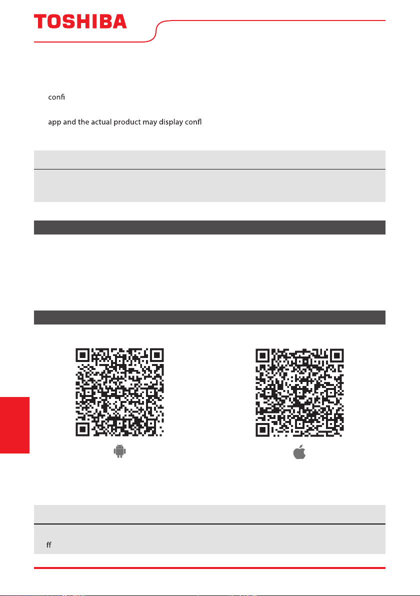
DOWNLOAD AND INSTALL THE APP
edoc RQ elppAedoc RQ diordnA
Scan to download app.
• You can also go to Google Play or App Store and search for Toshiba NA AC. For more information,
please refer to Toshiba Lifestyle website: www.toshiba-lifestyle.com
All the images in this manual are for reference only, your product and app may look slightly
di erent. The actual product and app instructions have to be considered.
NOTICE
4. To ensure proper scanning of the QR code, your smart phone must have at least a 5-megapixel
camera.
5. Due to unstable network connectivity, requests may time out. If this happens, re-run the network
guration.
6. Due to unstable network connectivity, commands may time out. If this happens, the smartphone
icting information. The information displayed on the
actual product is always the most accurate available. Refresh the app to re-sync.
Toshiba will not be responsible for any problems that could be caused by incompatibility or network
issues, your wireless router and mobile phone.
NOTICE
User Manual Page 29
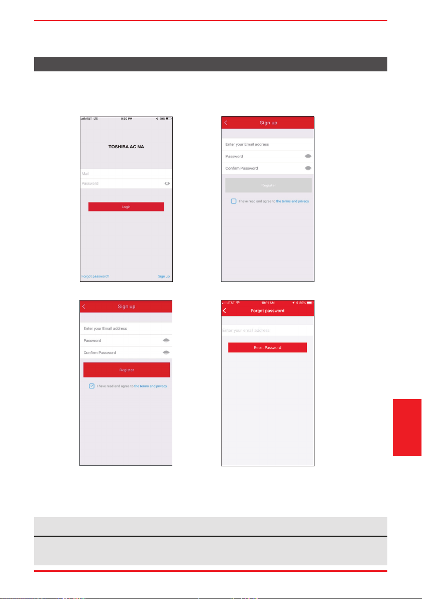
CREATE YOUR ACCOUNT
• Make sure your smartphone is connected to your wireless router and your wireless router has a
working 2.4GHz internet connection.
• It is recommended to activate your account immediately to be able to recover your password by email.
6.1 Press “Sign Up”. 6.2 Enter your email address and password.
6.3 Press “Registration”. 6.4 If you forget your password, press
“Forgot password?” on the main
menu and enter your email address.
Then press “Reset Password”.
• Make sure your smartphone is able to connect to the wireless network which will be used.
• Make sure also that the device is not connecting to other networks in range.
NOTICE
Remote Control and
App Instructions
Page 30 User Manual
ADDITIONAL APP AND SMART HOME FUNCTIONS
For additional instructions regarding the features of the app and Smart Home skill capabilities, scan
the QR code below.
Remote Control and
App Instructions
This device complies with Part 15 of the FCC Rules and it contains licence-exempt transmitter(s)/receiver(s)
that comply with Innovation, Science and Economic Development Canada’s licence-exempt RSS(s).
Operation is subject to the following two conditions:
(1) This device may not cause interference;and
(2) This device must acceptany interference,including interference that may cause undesired operation
of the device.
not expressly approved by the party responsible for compliance could void the user's authority to operate
the equipment.This device complies with FCC radiation exposure limits set forth for an uncontrolled
environment. In order to avoid the possibility of exceeding the FCC radio frequency exposure limits,
human proximity to the antenna shall not be less than 20cm (8 inches) during normal operation.
Declaration of conformity
CONTAINS FCC ID: 2ADQOMDNA21
CONTAINS IC : 12575A-MDNA21
Company will not be liable for any issues and problems caused by Internet, Wi-Fi/
Wireless Router and Smart Devices. Please contact the original provider to get further
help.
NOTE: This equipment has been tested and found to comply with the limits for a Class B digital device,
pursuant to part 15 of the FCC Rules. These limits are designed to provide reasonable protection against
harmful interference in a residential installation. This equipment generates, uses and can radiate radio
frequency energy and, if not installed and used in accordance with the instructions, may cause harmful
interference to radio communications. However, there is no guarantee that interference will not occur
in a particular installation. If this equ
ipment does cause harmful interference to radio or television
to try to correct the interference by one or more of the following measures:
--Reorient or relocate the receiving antenna.
--Increase the separation between the equipment and receiver.
--Consult the dealer or an experienced radio/TV technician for help.

Supplier's Declaration of Conformity
47 CFR § 2.1077 Compliance Information
Unique Identifier: RG57H4(B)/BGEFU1
Responsible Party U.S. Contact Information
Midea America Corporation
300 Kimball Dr
Parsippany NJ
07054
This device complies with Part 15 of the FCC Rules. Operation is subject to the
following two conditions: (1) This device may not cause harmful interference, and
(2) this device must accept any interference received, including interference that
may cause undesired operation.
Telephone number or internet contact information: Midea.com/us
FCC Compliance Statement ( products subject to Part 15)
Page 31User Manual

MANUAL DEL USUARIO
Tipo Portatil
Aire Acondicionado de Habitación
versión D - 10 - 2020
MAN
U
AL DEL
USU
ARI
O
RAC-PD1013CWRU
RAC-PD0812CRRU
RAC-PD1213CWRU
RAC-PD1414CWRU
Ti
po Portati
l
Aire Acon
d
iciona
d
o
d
e Ha
b
itación
versión D - 10 - 202
0
www.toshiba-lifestyle.com
Precauciones de Seguridad
Instrucciones de Operación
Instrucciones de Instalación
Instrucciones del Control
Remoto y del App
Soluciones de Problemas
Mantenimento Y Limpieza
Avisos de advertencia: antes de usar este
producto, lea atentamente este manual y
consérvelo para futuras referencias.
a cambios sin previo aviso para la mejora
del producto. Consulte con su distribuidor o
fabricante para obtener más detalles.
version A - 09 - 2022 (PREVIEW01)
Page 32 User Manual
Lea este Manual
En su interior encontrará muchos consejos útiles sobre como usar y mantener su acondicionador
de aire correctamente. Unos pocos cuidados por su parte pueden ahorrar una gran cantidad de
tiempo y dinero, alargando la vida útil de su acondicionador de aire. Encontrará muchas respuestas
a los problemas más comunes en el cuadro de solución de problemas – Podrá resolver la mayoría de
ellos rápidamente antes de llamar al servicio técnico. Estas instrucciones pueden no cubrir todas las
condiciones posibles de uso, así que sentido común y atención a la seguridad é necesario al instalar,
operar y mantener este producto.
Manual del propietario
Precauciones de Seguridad ............................................................................................... 33
Instrucciones de Operación ............................................................................................... 38
Instrucciones de Instalación .............................................................................................. 44
Mantenimiento y Limpieza ................................................................................................ 49
Soluciones de Problemas ................................................................................................... 50
Instrucciones del Control Remoto y del App .............................................................. 51
• Para obtener asistencia, llame el Central de Servicio Técnico al 1-855-204-5313.
• Este aparato no está diseñado a ser utilizado por personas (incluidos niños) con capacidades
físicas, sensoriales o mentales reducidas o falta de experiencia y conocimientos, a menos que
hayan recibido supervisión o instrucción sobre el uso del aparato por parte de una persona
responsable de su seguridad.
• Los niños deben supervisarse para asegurar que ellos no jueguen con el acondicionador de aire.
• El aparato deberá ser instalado de acuerdo con la norma nacional de instalación eléctrica.
• No utilizar su acondicionador de aire en una habitación húmeda, como un baño o una
lavandería.
PRECAUCIÓN
User Manual Page 33
PRECAUCIONES DE SEGURIDAD
Para evitar daños al usuario u otras personas y a la propiedad, las instrucciones que se muestran aquí
deben ser seguidas. Las operaciones incorrectas por la ignora de las instrucciones podría causar perjuicios
o lesiones. El nivel de riesgo está clasi cado por las siguientes indicaciones.
Precauciones
de Seguridad
ADVERTENCIA
Este símbolo indica una situación peligrosa que, si no evitada, podría
causar la muerte o lesiones graves.
PRECAUCIÓN
Este símbolo indica una situación peligrosa que, si no evitada, podría
resultar en lesiones leves o moderadas.
AVISO
Este símbolo aborda las prácticas no relacionadas con lesiones
físicas.
• Asegúrese de que el acondicionador de aire se ha instalado de forma segura y correcta de
acuerdo con las instrucciones de instalación de este manual. Guarde este manual para un posible
uso futuro en la extracción o instalación de esta unidad.
• Enchúfalo en el enchufe de alimentación eléctrica correctamente.
De lo contrario, puede causar una descarga eléctrica o un incendio debido a la excesiva
generación de calor.
• No modi car la longitud del cable de alimentación ni comparta la tomacorriente con
otros aparatos, ya que puede provocar una descarga eléctrica o un incendio debido al
sobrecalentamiento.
• Asegúrese siempre de una conexión a tierra e caz.
Una conexión a tierra incorrecta puede provocar una descarga eléctrica.
• Desenchufar la unidad si nota sonidos extraños o olores o humo proveniente de ella.
Un producto dañado puede causar incendio y descarga eléctrica.
• Ventile la habitación antes de utilizar el acondicionador de aire si hay una fuga de gas desde
otros aparatos.
• No accione ni detenga la unidad insertando o extrayendo el enchufe de la tomacorriente.
• No lo maneje con las manos mojadas o en ambientes muy húmedos.
Puede causar una descarga eléctrica.
• No permita que el agua entre en contacto con ninguna pieza eléctrica.
Puede causar fallas o descarga eléctrica.
• No lo use el enchufe si está suelto o dañado.
Puede causar incendio y descarga eléctrica.
• No lo use ni mantenga el cable de alimentación cerca de los aparatos de calefacción.
Puede causar incendio y descarga eléctrica.
• No lo use ningún dispositivo o material para la instalación que no se recomiende en este manual.
ADVERTENCIA
Page 34 User Manual
Precauciones
de Seguridad
• No desmonte ni modi que la unidad.
Puede causar fallas y descarga eléctrica.
• No dañe ni utilice un cable de alimentación alternativo.
Puede causar incendio y descarga eléctrica.
Si el cable de alimentación está dañado, debe ser reemplazado por el fabricante o un centro de
servicio técnico autorizado o una persona igualmente cali cada para evitar un peligro.
• No dirija el ujo de aire directamente a las personas para evitar posibles riesgos para la salud.
• No abra la unidad durante el funcionamiento.
Puede causar descarga eléctrica.
• No utilice el cable de alimentación cerca de gases in amables o combustibles, como gasolina,
benceno, diluyente, etc.
Puede causar una explosión o un incendio.
• No deje que los niños cuelguen el acondicionador de aire o el soporte.
Puede ocurrir una lesión grave.
• Evite el peligro de incendio o la descarga eléctrica. No utilice un cable de extensión ni un
enchufe adaptador. No extraiga ninguna clavija del cable de alimentación.
• Asegúrese de que el acondicionador de aire esté correctamente conectado a tierra. Para
minimizar descargas eléctricas y riesgos de incendio, es importante realizar una conexión a
tierra adecuada. El cable de alimentación está equipado con un enchufe de conexión a tierra
de tres clavijas para la protección contra los riesgos de choque.
• Su acondicionador de aire debe utilizarse en una tomacorriente de pared correctamente
conectado a tierra. Si la tomacorriente de pared que tiene intención de utilizar no está
adecuadamente conectada a tierra o protegida por un fusible de retardo de tiempo o un
disyuntor, pida a un electricista cuali cado que instale una tomacorriente adecuada. Asegúrese
de que la tomacorriente sea accesible después de la instalación de la unidad.
• Asegúrese de que el servicio eléctrico es adecuado para el modelo que ha elegido. Esta
información se puede encontrar en la placa de serie, que se encuentra en el lado del gabinete y
detrás de la rejilla.
• Cuando se va a quitar el ltro de aire, no toque las partes metálicas de la unidad.
Puede causar lesiones.
• Cuando la unidad necesite limpieza, apague la unidad y apague el disyuntor.
No limpie la unidad cuando la alimentación esté encendida, eso puede provocar un incendio,
una descarga eléctrica o lesiones.
• No coloque obstáculos alrededor de las entradas de aire o dentro de la salida de aire.
Puede causar fallas o un accidente.
• Limpie solo con un paño suave. No utilice detergentes fuertes que contengan cera o diluyentes,
ya que puede dañar el producto.
ADVERTENCIA
PRECAUCIÓN
User Manual Page 35
Precauciones
de Seguridad
PRECAUCIÓN
• Tenga cuidado al desempacar e instalar. Los bordes a lados podrían causar lesiones.
• No limpie el acondicionador de aire con agua.
El agua puede entrar en la unidad y degradar el aislamiento que podría conducir a una descarga
eléctrica.
• No lo guarda una mascot o plantas donde sera expuesto al ujo del aire directo.
Podría hacer daño a su mascot o planta.
• Sujete el enchufe junto a la cabeza cuando sacarlo.
De lo contrario, puede causar descarga eléctrica y daños.
• Asegúrese de que la instalación esté correctamente segura para prevenir el producto de posibles
quedas.
• No conecte objetos pesados en el cable de alimentación y asegúrese de que el cable no esté
comprimido.
De lo contrario, hay peligro de incendio o descarga eléctrica.
• Si hay agua derramada en la unidad, apague la unidad y apague el disyuntor. Aísle el suministro
tomando el enchufe y contacte un personal de servicio técnico cuali cado.
• No lo use cerca de estufas de gas o otros aparatos de combustión de gas, ya que el ujo de aire
puede afectar a la combustión de gas.
• No usar para ningún otro propósito que no sea la comodidad de la habitación.
No utilice este acondicionador de aire para conservar instrumentos de precisión, alimentos,
animales, plantas y objetos de arte. Puede causar deterioro.
• Apague el disyuntor si la unidad no se va a ser utilizada por un tiempo prolongado.
• Siempre inserte los ltros de forma segura. Limpie el ltro una vez cada dos semanas.
El funcionamiento sin ltros puede causar un error.
• No beba el agua de drenaje del acondicionador de aire.
Riesgo de incendio/
materiales inflamables
(Requerido para unidades
R32 / R290 solamente)
NOTA IMPORTANTE: Lea este manual
detenidamente antes de instalar o utilizar
su nueva unidad de aire acondicionado.
Asegúrese de guardar este manual para
futuras consultas.
Page 36 User Manual
Precauciones
de Seguridad
ADVERTENCIA
Este símbolo muestra que este aparato ha utilizado un refrigerante
in amable. Si el refrigerante está ltrado y exposto a una fuente de
ignición externa, hay riesgo de incendio.
PRECAUCIÓN
Este símbolo muestra que el manual de instrucciones debe leerse
cuidadosamente.
PRECAUCIÓN
Este símbolo muestra que un personal de servicio técnico debe
manipular este equipo con referencia al manual de instalación.
PRECAUCIÓN
Este símbolo muestra que la información está disponible, tanto al
manual de instrucciones o al manual de instalación.
EXPLICACIÓN DE LOS SÍMBOLOS MOSTRADOS EN LA UNIDAD
• No intente acelerar el proceso de descongelación o los métodos de limpieza que no son
recomendados por el fabricante.
• El aparato debe ser ubicado en una habitación sin fuentes de ignición en funcionamiento
continuo (por ejemplo, llamas abiertas o un aparato de gas en funcionamiento) o fuentes de
ignición comunes (por ejemplo, un calentador eléctrico en funcionamiento) cerca del aparato.
El aparato también debe ser ubicado en una habitación sin cualquer otra fuente de ignición.
• No perforar ni quemar.
• Tenga en cuenta que los refrigerantes pueden no contener olor.
• Mantenga las aberturas de ventilación libres de obstrucciones.
• La unidad solo debe ser atendida por un centro de asistencia autorizada Toshiba, llame al
Servicio al Cliente al 1-855-204-5313 para obtener asistencia técnica.
• El refrigerante in amable R32 se usa dentro del acondicionador de aire. Siga las instrucciones
cuidadosamente para manejar, instalar, limpiar y reparar el acondicionador de aire para evitar
daños o peligros. No deseche el acondicionador de aire en la basura común. Contacte la agencia
cuali cada para la eliminación adecuada.
• No maneje fuego ni dispositivos que generen chispas alrededor del acondicionador de aire
para evitar causar la ignición del refrigerante in amable utilizado. Siga cuidadosamente las
instrucciones para ubicar o arreglar el acondicionador de aire para evitar que se produzcan
daños mecánicos.
ADVERTENCIA (solo para usar refrigerante R32)
User Manual Page 37
El cable de energía que acompaña este
acondicionador de aire contiene un dispositivo
de detección de corriente diseñado para
reducir el riesgo de incendio.
En el caso del cable de energía esté dañado, no
se puede reparar. Debe sustituirlo por un cable
del fabricante.
Precauciones
de Seguridad
• No utilice este dispositivo para encender o apagar la unidad.
• Asegúrese siempre de que el botón RESET esté pulsado para una operación correcta .
• El cable de energía debe ser reemplazado si lo falla al reiniciar mismo cuando el botón TEST esté
pulsado o no se puede reiniciarse. Póngase en contacto con el servicio de atención al cliente.
Toma de Tierra Tipo Pared Receptáculo
Do not, under any
circumstances, cut,
remove or bypass
the grounding prong.
Power supply cord with 3-prong grounding
plug and current detection device.
El cable de energía contiene un dispositivo de
medición que detecta daños en el proprio cable.
Pruebelo de la siguiente manera:
1. Enchufe el acondicionador de aire.
2. El cable de energía tendrá DOS botones en
el cabezal del enchufe. Pulse el botón TEST.
Notará un clic a medida que aparezca el
botón RESET.
3. Pulse el botón RESET. Notará un clic a medida
que el botón se activa.
4. El cable de energía ahora está energizando la
unidad. (En algunos productos esto también
se indica mediante una luz en el cabezal del
enchufe.)
RESET
TEST
Enchufe y pulse
el botón RESET
Operación del dispositivo de corriente
AVISO
AVISO
Nunca, en ningún
caso, corte, remueve
ni pasar por la
conexión a la tierra.
Cable de energía con enchufe de conexión a tierra de
3 clavijas y dispositivo de detección de corriente.

Page 38 User Manual
INSTRUCCIONES DE OPERACIÓN
Preparación
Panel de control
Mango de
traslado
(ambos os lados)
Deflector de aire
(oscilación
automática)
Rodízio
Panel
TraseraFrente
Soporte del enchufe
Soporte del cable
Salida de drenaje
de la bandeja inferior
Salida del cable
Salida de drenaje
(solo para modelos
heat pump)
Filtro de aire
superior
(detrás de la rejilla)
Entrada de aire
superior
Salide de aire
Filtro de aire inferior
Toma de aire inferior
Salida de drenaje
6&$/(
Faja de Temperatura de Funcionamiento de la Unidad:
Modo Faja de Temperatura
Enfriamiento (Cool) 62°F ~ 95°F (17°C ~ 35°C)
Dehumidi cación (Dry) 55°F ~ 95°F (13°C ~ 35°C)
Calentamiento (Heat - solo tipo heat pump) 41°F ~ 86°F (5°C ~ 30°C)
Calentamiento (Heat - solo tipo electrical heat mode) ≤ 86°F (30°C)
Instrucciones
de Operación
Instalación de la Manguera de Escape:
La manguera de escape y el adaptador debe instalarse o quitarse de acuerdo con el modo de uso.
Para los modos enfriamiento (COOL), calentamiento (HEAT - tipo heat pump) o automático (AUTO), la
manguera de escape debe ser instalada.
Para los modos ventilación (FAN), dehumidificación (DRY o calentamiento (HEAT - tipo electric heat),
la manguera de escape debe ser retirada.
User Manual Page 39
Instrucciones
de Operación
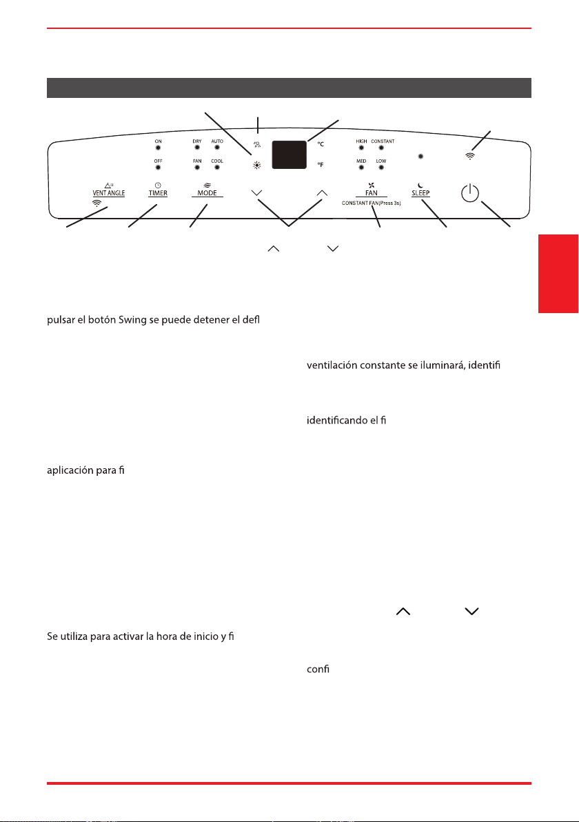
Característica del Panel de Control
Botón Oscilación (Swing)
Se utiliza para iniciar la función de oscilación
automática. Cuando la operación está activada, al
ector
en el ángulo deseado.
Función Connect (Smart models only)
Se utiliza para iniciar el modo de conexión
inalámbrica. Para empezarlo, encienda el
acondicionador de aire y, a continuación, pulse el
botón Swing durante 3 segundos. La pantalla LED
mostrará ‘AP’ para indicar que la unidad está en
modo de conexión inalámbrica.
Consulte las instrucciones de conexión de la
nalizar el proceso de conexión.
Si la conexión se realiza correctamente, la unidad
saldrá del modo de conexión inalámbrica e iluminará
el LED del inalámbrico. Si la conexión falla, la
unidad saldrá del modo de conexión inalámbrica
automáticamente después de 8 minutos y el LED del
inalámbrico no se iluminará.
NOTA: El proceso de conexión inalámbrica debe
completarse dentro de los 8 minutos posteriores a la
alimentación del acondicionador de aire.
Botón del Temporizador (Timer)
nal en las
operaciones de inicio y parada del Temporizador.
La luz de encendido o apagado del temporizador se
iluminará despues del ajuste seleccionado.
Botón de Velocidad del Ventilador (Fan)
Pulse para controlar la velocidad del ventilador
en cuatro pasos: LOW, MID, HIGH y AUTO. La luz de
velocidad del ventilador seleccionada (excepto AUTO)
se iluminará. Cuando se selecciona AUTO, no se
iluminarán las luces.
NOTA: Aplicable a modelos con la función de
ventilación constante. En el modo COOL o DRY,
pulse el botón Fan durante 3 segundos para
activar o desactivar la función de ventilación
constante.
Cuando la función está encendida, la luz de la
cando
el funcionamiento continuo del ventilador para
la enfriamiento. Cuando la función está apagada,
la luz de la ventilación constante se apagará,
nal del ciclo del ventilador, a
través de la parada del compressor.
Botón del Modo (Mode)
Selecciona el modo de funcionamiento
deseado. Cada vez que pulsa el botón, un
modo és seleccionado en una secuencia que
va desde AUTO, COOL, DRY, FAN y HEAT
(solo modelos heat pump). La luz de modo
se iluminará y indicará el modo seleccionado.
Para cambiar entre °F o °C, mantenga pulsados
simultáneamente los botones Arriba y Abajo
durante 3 segundos.
Botones Arriba ( ) y Abajo ( )
Se utiliza para aumentar/disminuir la
temperatura en incrementos de 1°F (o 2°F) /1°C
en un alcanze de 62°F/17°C a 86°F/30°C o la
guración del Temporizador en un alcanze
de 0 a 24 horas.
Para cambiar entre °F o °C, mantenga pulsados
simultáneamente los botones Arriba y Abajo
durante 3 segundos.
Botón Encender/Apagar (Power)
Interruptor de encendido/apagado.
Botón
Swin
g
Visor de LEDs Wireless (solo
modelos SMART)
MyTemp
Luz indicadora de Heat Mode
(solo modelos heat pump)
MyTemp
HEAT
3 seconds
Botón
Timer
Botón
Mode
Botón
Fan
Botón
Sleep
Botón
ON/OFF
Botones
Arriva
(
)
y
Aba
j
o
(
)
Page 40 User Manual
Botón del modo Sueño (Sleep)
Se utiliza para iniciar la operación SLEEP.
Pantalla de LEDs
Muestra la temperatura ajustada en °F (Grados
Fahrenheit) o °C (Grados Celsius) y los ajustes del
Temporizador Automático. En los modos DRY y
FAN, muestra la temperatura ambiente.
Códigos de Error y códigos de protección:
E1 - Error en el sensor de temperatura de la
habitación.
E2 - Error en el sensor de temperatura del
evaporador.
E3 - Error del sensor de temperatura del
condensador (modelos selecionados).
E4 - Error en la comunicación de la pantalla del
panel.
P1 - La bandeja inferior está llena: conecte
la manguera de drenaje y drene el agua
acumulada. Si el código de protección se
repite, llame al servicio técnico.
Cuando ocurre una de las fallas anteriores,
apague la unidad y compruebe si hay
obstrucciones. Reinicie la unidad. Si la falla
persiste, apague la unidad y desenchufe el
cable de alimentación. Pongáse en contacto
el fabricante o uno de sus agentes de servicio
técnico o una persona similarmente cali cada
para el servicio técnico.
AVISO
Instrucciones de Funcionamiento
Funcionamiento en Enfriamiento (COOL)
• Pulse el botón “MODE” hasta que se encienda la
luz indicadora “COOL”.
• Pulse los botones de ajustes Arriba (
) o Abajo
( ) para seleccionar la temperatura ambiente
deseada. La temperatura se puede ajustar dentro
de una faja de 62°F~86°F/17°C~30°C.
• Pulse el botón “FAN SPEED” para elegir la
velocidad del ventilador.
Funcionamiento en Calentamiento (HEAT)
(disponible solo en modelos HEAT)
• Pulse el botón “MODE” hasta que se encienda la
luz indicadora “
” .
• Pulse los botones de ajustes Arriba (
) o Abajo (
)
• para seleccionar la temperatura ambiente
deseada. La temperatura se puede ajustar dentro
de una faja de 62°F~86°F/17°C~30°C.
• Pulse el botón “FAN SPEED” para elegir la velocidad
del ventilador. Para algunos modelos, la velocidad
del ventilador no se puede ajustar mientras esté en
modo HEAT.
Funcionamiento en dehumidificación
(DRY)
• Pulse el botón “MODE” hasta que se encienda la
luz indicadora “DRY” .
• En este modo, no és posible seleccionar
una velocidad del ventilador ni ajustar la
temperatura. El motor del ventilador funciona en
baja velocidad.
• Mantenga las ventanas y puertas cerradas para
un mejor efecto deshumidi cante.
Funcionamiento automático (AUTO)
• Al con gurar el acondicionador de aire en el
modo AUTO, seleccionará automáticamente
enfriamiento, calentamiento (solo modelos heat
pump) o el funcionamiento solo del ventilador,
dependiendo de la temperatura que haya
seleccionado y de la temperatura ambiente actual.
• El acondicionador de aire controlará
automáticamente la temperatura ambiente hasta
la temperatura con gurada por usted.
• Bajo el modo AUTO, no és posible seleccionar la
velocidad del ventilador.
Funcionamiento del FAN
• Pulse el botón “MODE” hasta que se encienda la
luz indicadora ”FAN“ .
• Pulse el botón “FAN SPEED” para elegir la
velocidad del ventilador. No se puede ajustar la
temperatura.
• No conecte el conducto a ninguna ventana.
Instrucciones
de Operación
User Manual Page 41
TIMER: Funcionamiento Auto Start/Stop
• Cuando la unidad esté encendida, al pulsar el
botón del Temporizador se iniciará el programa
de detención automática. La luz indicadora TIMER
OFF se encenderá. Pulse el botón Arriba (
) o
Abajo (
) para seleccionar la hora deseada. Pulse
de nuevo el botón TIMER en 5 segundos.
El programa de inicio automático se iniciará y la
luz indicadora TIMER ON se encenderá. Pulse el
botón Arriba (
) o Abajo ( ) para seleccionar la
hora de inicio automática deseada.
• Cuando la unidad esté apagada, pulse el botón
Temporizador para iniciar el programa de
inicio automático. Pulsando de nuevo en cinco
segundos se iniciará el programa de detención
automática.
• Mantenga pulsado el botón Arriba (
) o
Abajo (
) para cambiar la hora automática en
incrementos de 0.5 horas, hasta 10 horas y, a
continuación, en incrementos de 1 hora hasta
24 horas. El control contará el tiempo restante
hasta el inicio.
• El sistema volverá a enseñar automáticamente el
ajuste de la temperatura anterior caso no tenga
ninguna operación dentro de 5 segundos.
• Al encender o apagar la unidad en cualquier
guración del
temporizador a 0.0, se cancelará la operación de
inicio/parada automática.
• En caso de malo funcionamiento, la operación de
inicio/parada automática también se cancelará.
Funcionamiento del Modo Sueño (SLEEP)
Al pulsar este botón se aumentará (durante la
operación de enfriamiento) o se disminuirá (durante
operación de calentamiento, en modelos aplicables)
1 °F/1 °C después de 30 minutos. La temperatura
volverá a aumentar (enfriar) o disminuir (calentar)
en otros 1 °F/1 °C después de 30 minutos
adicionales. Esta nueva temperatura se mantendrá
durante 7 horas antes de volver a la temperatura
guración
terminará la operación del Sleep y la unidad seguirá
funcionando como se programó originalmente.
AVISO
La función de funcionamiento SLEEP no está
disponible en los modos FAN o DRY.
Otras Características
Función MyTemp
Esta función solamente puede activarse desde el
control remoto. El control remoto sirve como un
termostato remoto, permitiendo un control de
temperatura preciso en su ubicación conteniendo
26 pies de distancia del acondicionador de aire.
Para activar la función MyTemp, apunte el
control remoto a la unidad y pulse el botón
MyTemp.La pantalla del control remoto mostrará
la temperatura real en su ubicación y debe estar
dentro de los 26 pies del acondicionador de aire
para que funcione. El control remoto enviará esta
señal al acondicionador de aire cada 3 minutos
hasta que se vuelva a pulsar el botón MyTemp.
guración
del MyTemp durante culquier intervalo de 7
minutos, la unidad saldrá del modo MyTemp.
NOTA: Esta función no está disponible en modo
FAN o DRY.
Reinicio Automático
Si la unidad se apaga inesperadamente debido a
un corte de energía, se reiniciará con la función
previamente establecida automáticamente cuando
se reanude la alimentación.
Aguarde 3 Minutos Antes de Reanudar el
Funcionamiento
Después de que la unidad se haya detenido, no
se puede reiniciar hasta que haya transcurrido
3 minutos. Esto es para proteger la unidad. El
funcionamiento se reanudará automáticamente
después de 3 minutos.
Ajuste de la Dirección del Flujo de Aire
ector se puede ajustar automáticamente con
el botón SWING.
• Cuando la alimentación está encendida, el
ector se abre completamente.
• Pulse el botón SWING del panel o del control
remoto para iniciar la función de oscilación
ector se moverá hacia arriba
y hacia abajo automáticamente.
ector con las manos.
Instrucciones
de Operación
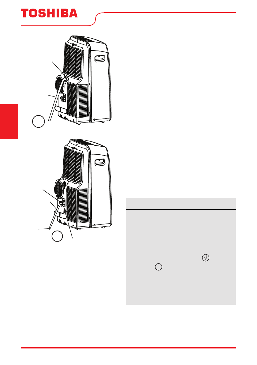
Page 42 User Manual
Drenaje del Agua
• Durante los ciclos de los modos DRY, retire el
tapón de drenaje superior de la parte trasera de
la unidad e instale el conector de drenaje de 5/8
(conector “hembra” universal) con una manguera
de 3/4” (comprada localmente).
Para los modelos sin conector de drenaje,
simplemente conecte la manguera de drenaje
al orificio. Coloque el extremo de la manguera
directamente en el área de drenaje que está
utilizando.
¥
Manguera
de drenaje
Retire el tapón
superior de
drenaje
• Para los modelos heat pump, retire el tapón de
drenaje central de la parte posterior de la unidad
e instale el conector de drenaje de 5/8” (conector
“hembra” universal) con una manguera de 3/4”
(no incluida). Para los modelos sin conector de
drenaje, simplemente conecte la manguera de
drenaje al conector. Coloque el extremo de la
manguera directamente en el área de drenaje que
está utilizando.
AVISO
En el modo Heat Pump la manguera de drenaje
se puede elevar hasta 6 pies (1,8 m). Dirija la
manguera hacia el desagüe, asegurándose de
que no haya torceduras que limiten el flujo
de agua estricto. Coloque el extremo de la
manguera en el desagüe y asegúrese de que
el extremo de la manguera esté dirigido hacia
abajo del fabricante. Ver Figs. con ).
Figuras con
X
son instalaciones no
recomendadas por el fabricante. Cuando
no se usa la manguera de drenaje continuo,
asegúrese de que el tapón de drenaje y la perilla
correspondientes estén instalados firmemente
para evitar fugas.
¥
Adaptador
de la
manguera
de drenaje
Manguera
de drenaje
Retire el tapón
medio de
drenaje
Solo unidades
modelos heat
pump
Instrucciones
de Operación
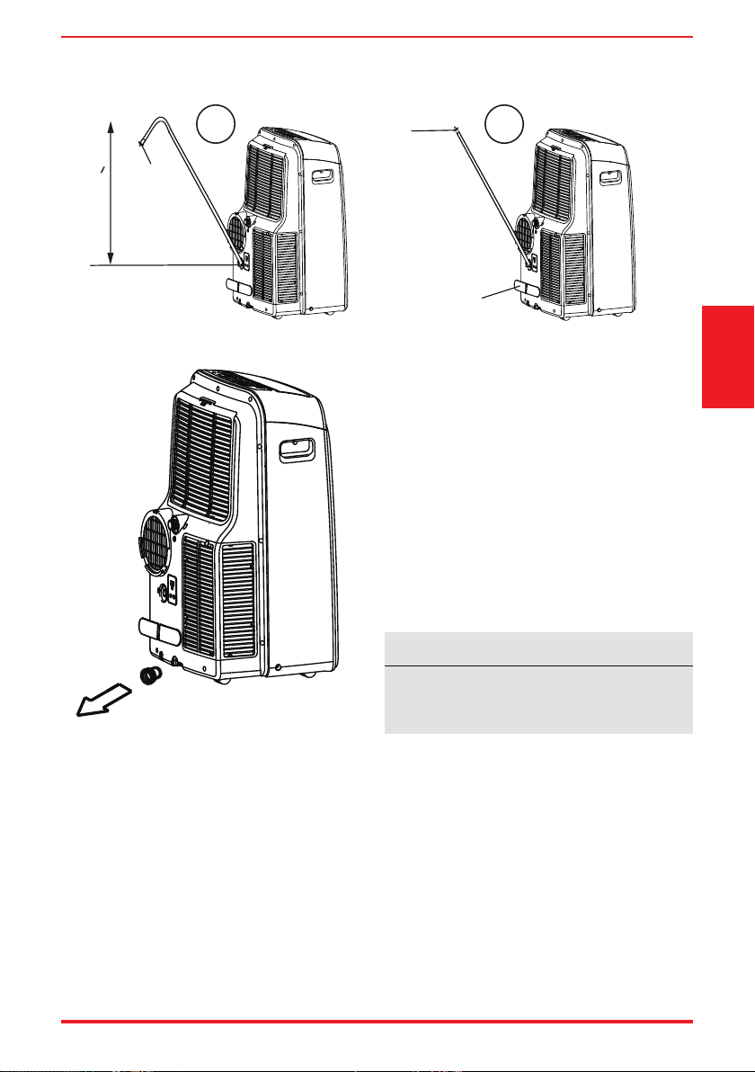
User Manual Page 43
Instrucciones
de Operación
AVISO
Asegúrese de volver a instalar rmemente el
tapón de drenaje inferior para evitar fugas
antes de usar la unidad.
X
Presione el soporte del
cable de alimentación
en la trasera del
aparato.
¥
Elevación de la
manguera < 6ft
Adaptador
de la
manguera
de drenaje
Adaptador
de la
manguera
de drenaje
Solo unidades modelos heat
p
um
p
• Cuando el nivel de agua de la bandeja
inferior alcanza un nivel predeterminado,
la unidad suena 8 veces. La pantalla de LED
muestra “P1.” En este momento el proceso
de aire acondicionado / deshumidi cación
se detendrá inmediatamente. Sin embargo,
el motor del ventilador continuará operando
(este procedimiento es normal). Mueva
cuidadosamente la unidad a un lugar donde
es posible drenar, retire el tapón de drenaje
inferior y deje que el agua drene. Vuelva a
instalar el tapón de drenaje inferior y reinicie la
máquina hasta que desaparezca el error “P1”. Si
el error se repite, llame al servicio técnico.
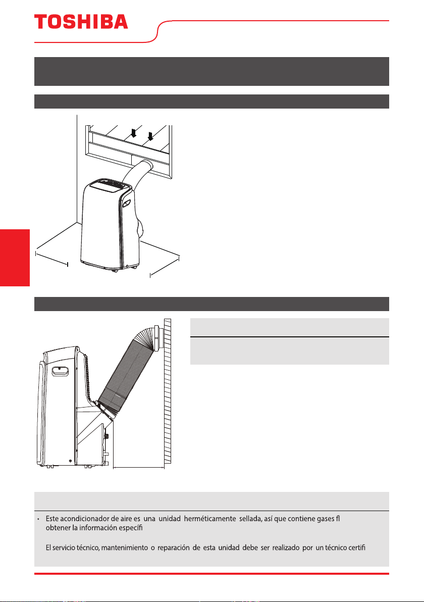
Page 44 User Manual
INSTRUCCIONES DE INSTALACIÓN
Elección de la Ubicación Correcta
Instalación Recomendada
50 cm
19.7 inch
50 cm
19.7 inch
Su ubicación de instalación debe cumplir los siguientes
requisitos:
• Asegúrese de instalar la unidad en una supercie
uniforme para minimizar el ruido y las vibraciones.
• La unidad debe instalarse cerca de un enchufe
conectado a tierra y el sistema de drenaje de la
bandeja (que se encuentra en la parte trasera de la
unidad) debe ser accesible.
• La unidad debe estar situada al menos a 19.7”
(50cm) de la pared más cercana para garantizar la
efectividad adecuada.
• NO cubrir las entradas, salidas o receptor de señal
remoto de el unidad, ya que esto podría causar
daños en la unidad.
AVISO Acerca de los gases fl uorados
uorados. Para
ca sobre el tipo de gas y la cantidad, consulte la etiqueta correspondiente en
la propia unidad.
•
cado.
• El reciclaje del producto debe realizarse de acuerdo con las regulaciones locales.
AVISO
La apariencia de su unidad puede ser un tanto
diferente.
50cm
19.7inch
Instrucciones
de Instalación
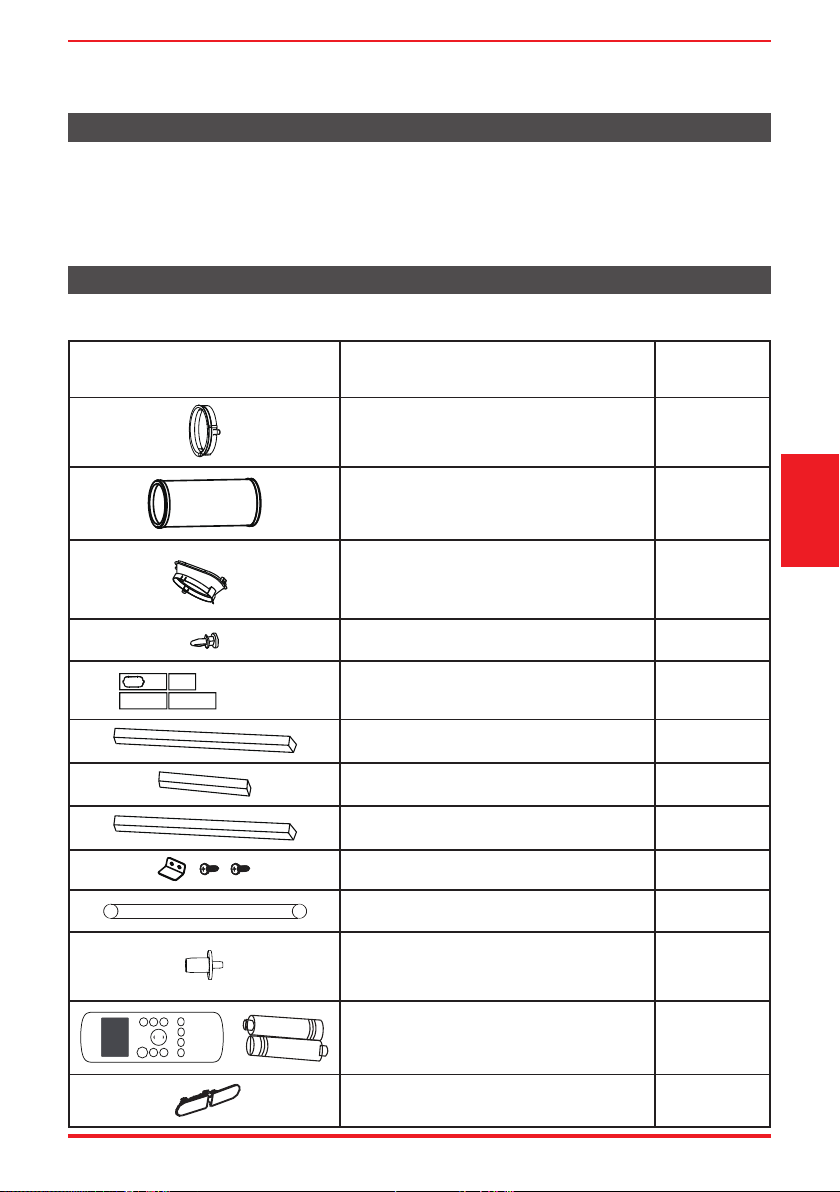
User Manual Page 45
Accesorios
El kit de instalación de ventanas es adaptable a ventanas de 19,4’’-62,2’’ (49,3-158,1 cm).
DescripciónPieza
Adaptador para unidad
Conducto de aire de escape
Deslizadores de ventana
Manguera de escape
Tornillo
Junta de espuma A (adhesivo)
Junta de espuma B (adhesivo)
Junta de espuma C (no adhesivo)
Soporte de seguridad y 2 tornillos
Manguera de drenaje
Adaptor para manguera de drenaje
((Solo para el modo heat pump)
Control remoto y baterías (pilas)
(Solo modelos con control remoto)
1 pieza
1 pieza
1 pieza
1 conj
2 piezas
1 pieza
1 pieza
4 piezas
2 piezas
1 conj
1 conj
Cantidad
1
pieza
Soporte del cable de alimentación
Herramientas Necesarias
• Destornillador Phillips
• Regla o cinta métrica
• Tijera o cuchillo
• Sierra (opcional, para acortar el adaptador de ventana para ventanas estrechas).
Instrucciones
de Instalación
3 pieza
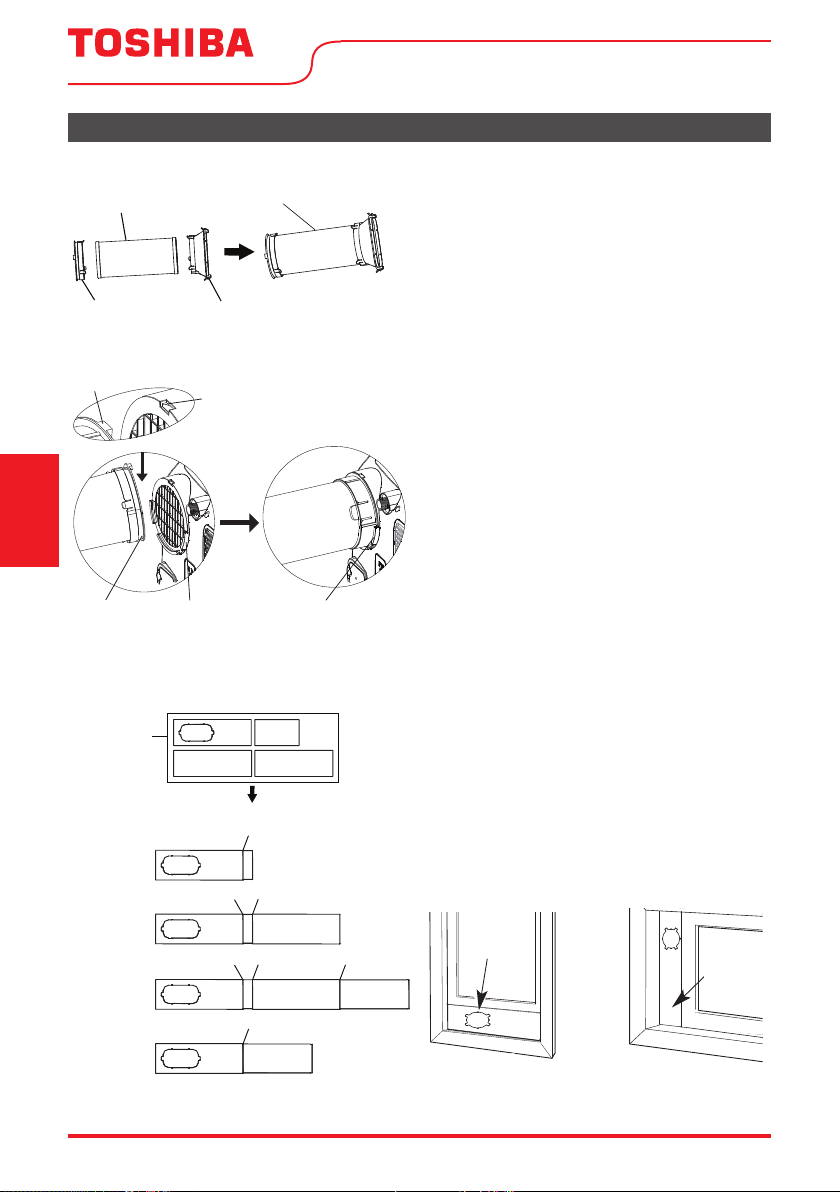
Page 46 User Manual
Kit de Instalación en Ventanas
1: Preparando el conjunto de la manguera
de escape
Presione la manguera de escape en el Paso de
escape de aire y en el adaptador, abrazando
automáticamente por las hebillas elásticas de los
adaptadores.
2: Instale el conjunto de la manguera de
escape en la unidad
Inserte el lado del adaptador de la unidad del
conjunto de la manguera de escape en la ranura
de la salida de aire en la parte trasera de la
unidad. Alinear el gancho del adaptador con el
asiento en la salida de aire y deslizamiento el
conjunto hacia abajo hasta que se asiente.
3: Preparando el Deslizador de ventana
ajustable
1. Conforme las dimensiones de la ventana,
ajuste el tamaño del deslizador de ventana.
2. Si la longitud de la ventana requiere dos
o más deslizantes, utilice el perno para fijar
los deslizadores una vez que se ajusten a la
longitud adecuada.
Manguera
de escape
Manguera de escape
ensamblada
Adaptor en
la unidad
Pasaje del
aire de escape
Enganche
Asiento del agujero
Ranura
inferior
Adaptador
Asegúrese de que el
adaptador se inserta
en el ranura inferior
de la salida de aire.
1+2:
Tornillo
1+2+3:
TornilloTornillo
1+2+3+4:
TornilloTornilloTornillo
1+4:
Tornillo
Deslizadores
de la ventana
Después del montaje
Antes del montaje
Hung Window Sliding Window
Window
slider A
Window
slider A
Tipo de Ventana
Deslizador de
Ventana A
Deslizador
de Ventana
A
Ventana de deslizarVentana de colgar
Instrucciones
de Instalación
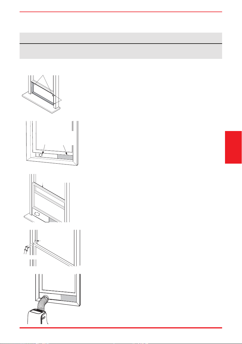
User Manual Page 47
Tipo 1: Instalación de ventanas de colgar
1. Corte el sello de espuma adhesiva A y B en tiras de acuerdo
con las longitudes adecuadas, y adjúntela a la faja de la ventana
y el marco como se muestra.
2. Inserte el conjunto deslizador de ventana en la abertura de la
ventana.
3. Corte el sello de espuma C (no adhesiva) para que coincida con
el ancho de la ventana. Inserte el sello entre el vidrio y el
marco de la ventana para evitar que el aire y los insectos entren
en la habitación.
4. Si lo desea, instale el soporte de seguridad con 2 tornillos como
se muestra.
5. Inserte el adaptador del deslizador de la ventana en el ori cio
del deslizador de la ventana.
AVISO
Una vez preparado el conjunto de la manguera de escape y el deslizador de ventana ajustable, elija
uno de los dos siguientes métodos de instalación.
Window
slider A
Window
slider B
(if required)
Deslizador
de Ventana
A
Deslizador
de Ventana B
(si necesario)
Sello de espuma B
(Adhesivo más corto)
Foam seal C
(Non-adhesive type)
Sello de espuma C
(No adhesivo)
Sello de
espuma A
(Adhesivo)
Security Bracket
2 Screws
Soporte de seguridad
2 Tornillos
Instrucciones
de Instalación
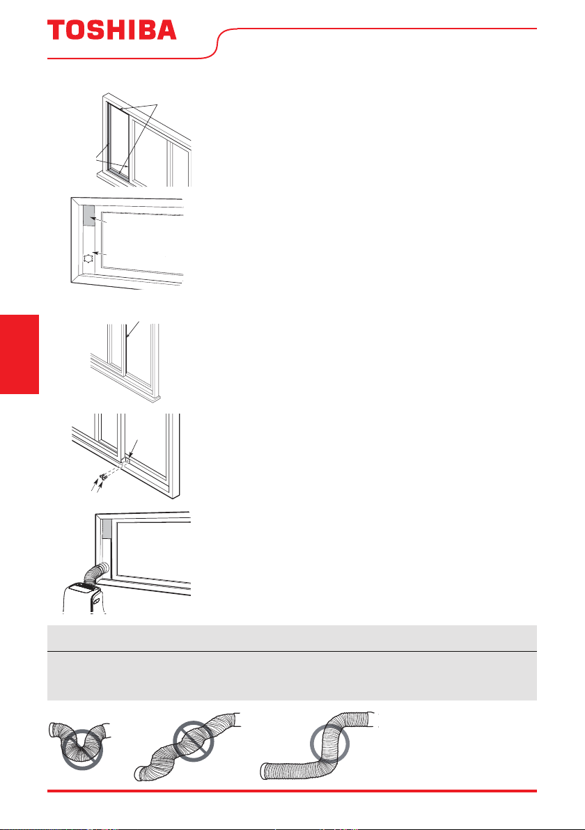
Page 48 User Manual
Tipo 2: Instalación de ventanas de deslizar
1. Corte el sello de espuma adhesiva A y B tiras a las
longitudes adecuadas, y adjúntelas a la faja de la ventana y
el marco como se muestra.
2. Inserte el conjunto del Deslizador de Ventana en la apertura de
la ventana.
3. Corte sello de espuma C (no adhesivo) para que coincida con la
altura de la ventana. Inserte el sello de espuma entre el vidrio
y el marco de la ventana para evitar que el aire y los insectos
entren en la habitación.
4. Si lo desea, instale el soporte de seguridad con 2 tornillos como
se muestra.
5. Inserte el adaptador del deslizador de la ventana en el ori cio
del deslizador de la ventana.
AVISO
Para garantizar un funcionamiento correcto, NO extienda demasiado ni doble la manguera. Asegúrese de que no haya
objetos acerca de una distancia de 20” (500 mm) de la manguera de escape. Todas las ilustraciones de este manual
son solo para nes explicativos, su acondicionador de aire puede ser ligeramente diferente de lo que se muestra.
Instrucciones
de Instalación
Window slider A
Window slider B
(if required)
Deslizador
de Ventana
Deslizador de Ventana
(si necesario)
Foam seal C
(Non-adhesive type)
Sello de espuma C
(No adhesivo)
(Adhesive
type-shorter)
s
eal A
sive
y
pe)
Sello de espuma B
(Adhesivo más corto)
Sello de
espuma A
(Adhesivo)
2 Screws
Security
Bracket
Soporte de
seguridad
2 Tornillos
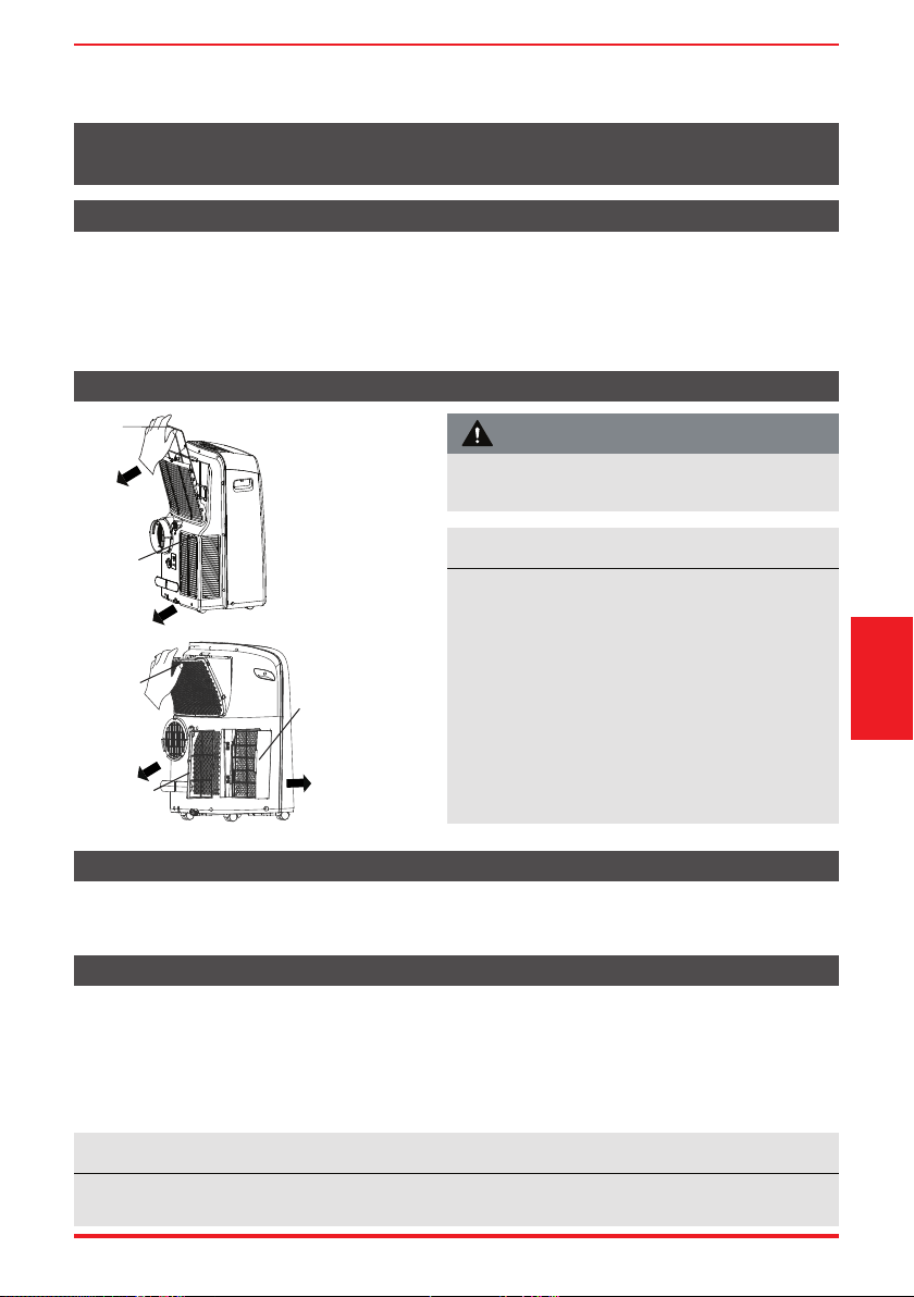
User Manual Page 49
Limpieza del fi ltro de aire
Limpieza del AC Portátil
Almacene la unidad cuando no esté en uso
Precauciones de Seguridad
MANTENIMIENTO Y LIMPIEZA
Mantenimient
y Limpieza
• Desenchufe siempre la unidad antes de limpiarla o repararla.
• NO use líquidos o productos químicos inflamables para limpiar la unidad.
• NO lavar la unidad con agua corriente. Hacerlo causa peligro eléctrico.
• NO opere la unidad si la fuente de alimentación se dañó durante la limpieza. Un cable de
alimentación dañado debe ser reemplazado por uno nuevo del fabricante.
Limpie con un paño húmedo que no suelte hilos y con detergente suave. Sécala con un paño seco que no
suelte hilos.
• Drene la bandeja de recolección de agua de la unidad de acuerdo con las instrucciones en la próxima sección.
• Haga funcionar la unidad en modo FAN durante 12 horas en una habitación cálida para secarla y evitar el moho.
• Apague la unidad y desenchúfela.
• Limpiar el filtro de aire de acuerdo con las instrucciones de la sección anterior. Vuelva a instalar el
filtro limpio y seco antes de guardarlo.
• Retire las baterías (pilas) del control remoto.
Retire el
filtro de aire
Filtro
superior
(sacar)
Saque el
filtro inferior
Filtro inferior B
(sacar)
Filtro inferior A
(Presione la rejilla
ligeramente hacia
abajo y saque el filtro
inferior A al mismo tiempo)
Filtro de aire
superior
(filtro combinado
con rejilla, sacar)
Solo para MODELOS
RAC-PD1414CWRU
Solo para MODELOS
RAC-PD0812CRRU,
RAC-PD1013CWRU y
RAC-PD1213CWRU
AVISO
Asegúrese de almacenar la unidad en un lugar fresco y oscuro. La exposición a la luz solar directa o al
calor extremo puede acortar la vida útil de la unidad.
Informaciones de mantenimiento
• Asegúrese de limpiar el ltro de aire cada 2
semanas para un rendimiento óptimo.
• La bandeja de recolección de agua debe drenarse
inmediatamente después de que ocurra el error P1
y antes del almacenamiento para evitar el moho.
• En hogares con animales, deberá limpiar
periódicamente la parrilla para evitar el bloqueo
del ujo de aire debido al pelo de eses.
• RAC-PD0812CRRU, RAC-PD1013CWRU and RAC-
PD1213CWRU: Los ltros de aire están integrados
y forman parte de la rejilla trasera.
NO opere la unidad sin ltro porque la suciedad e
hilos puden obstruir y reducir el rendimiento.
ATENCIÓN
Page 50 User Manual
SOLUCIONES DE PROBLEMAS
Solución
de Problemas
Antes de llamar al servicio técnico, revise esta lista. Puede ahorrarle una gran cantidad de tiempo y dinero. Esta
lista incluye ocurrencias comunes que no son consecuencia de un trabajo o materiales defectuosos en el equipo.
AVISO
¡No agregue extensión a la(s) manguera(s) de escape!
Problema Solución
El aire
acondicionado no
pone en marcha
cuando pulsa el
botón ON/OFF
Muestra el código de error P1 y signi ca que la bandeja de recolección de agua está llena.
Apague la unidad, drene el agua de la bandeja de recolección de agua y reinicie la unidad.
Si la temperatura ambiente es más baja que la temperatura con gurada en el modo
enfriamiento (COOL), restablezca la temperatura.
El aire de la
unidad no enfría
adecuadamente.
Filtro de aire sucio o restringido. Limpie el ltro. Desenchufe la unidade y consulte la
sección Cuidado y Limpieza.
La manguera de escape no está conectada o está bloqueada. Apague la unidad, desconecte
la manguera, veri que que no haya obstrucciones y vuelva a conectar la manguera.
La temperatura está con gurada demasiado alta, ajuste la temperatura a una
con guración más baja.
Asegurese de que puertas o ventanas estén cerradas.
El área de la habitación puede ser demasiado grande; vuelva a comprobar el área de
enfriamiento.
Asegurese de que cualquier puerta o ventana estén abiertos, lo que puede permitir
que el aire frío escape. Cierre las puertas y ventanas o registros.
La unidad hace
ruido y / o vibra
demasiado
El piso no está nivelado. Coloque la unidad sobre una super cie plana y nivelada.
Filtro de aire sucio o restringido. Limpie el ltro. Desenchufe la unidade y consulte la
sección Cuidado y Limpieza.
La unidad emite un
gorgoteo
Ese sonido es del ujo de refrigerante pasando por la unidad. Sonido normal.
La unidad no se
conecta a
Inalámbrico o
Aplicación
no funciona
(algunos
modelos)
Para obtener más ayuda y consejos de solución de
problemas, siga el link de este código QR:
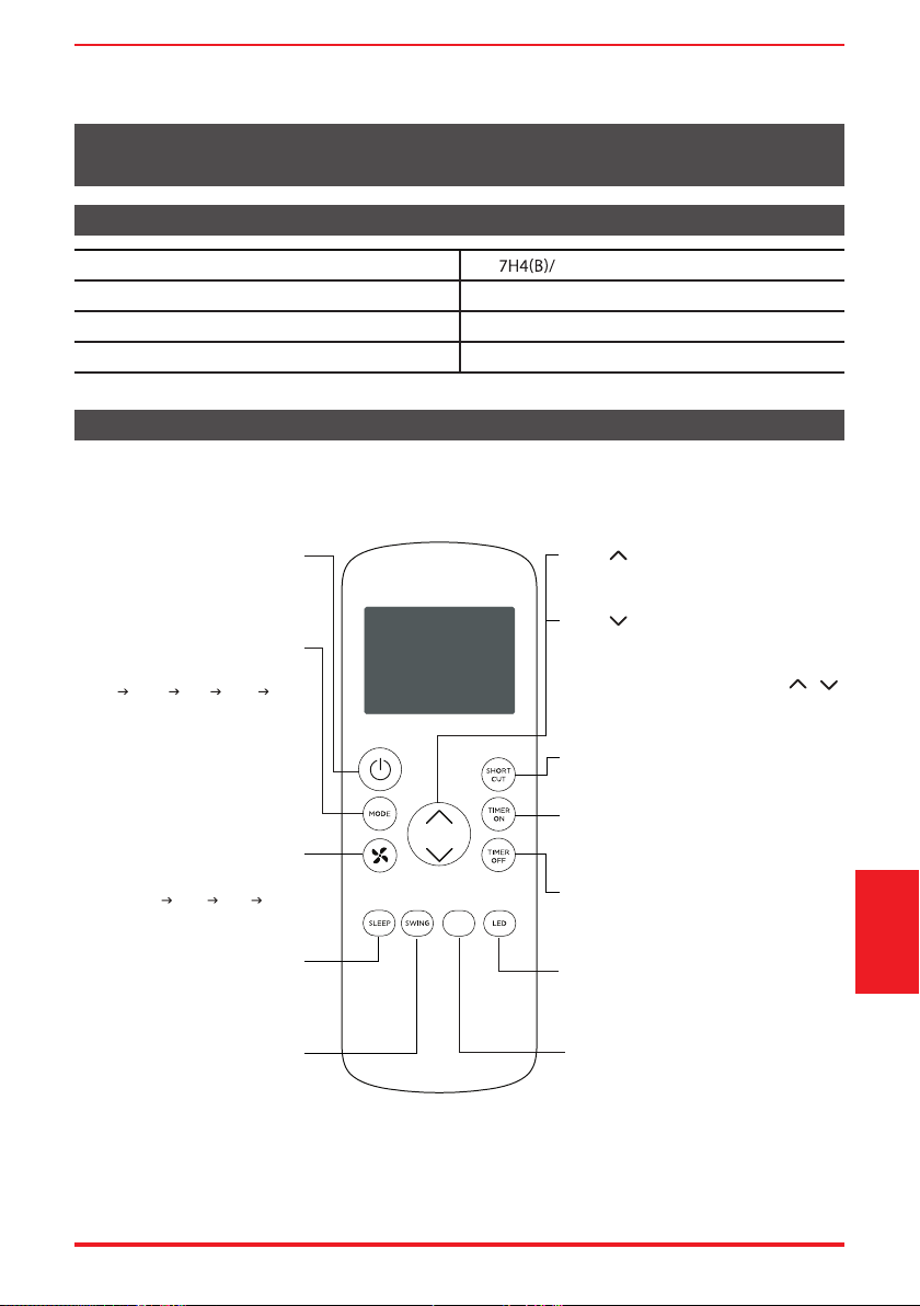
User Manual Page 51
Especifi caciones del Control Remoto
Funcionamiento de los Botones
INSTRUCCIONES DEL CONTROL REMOTO Y DEL APP
Antes de empezar a utilizar el nuevo acondicionador de aire, asegúrese de familiarizarse con su control remoto.
Lo que sigue es una breve introducción al propio control remoto. Para obtener instrucciones sobre como
operar el acondicionador de aire, consulte la sección Instrucciones de funcionamiento de este manual.
Model RG5 BGEFU1
Voltaje nominal 3.0V (Dry batteries R03/LR03x2)
Faja de recepción de señal 26 ft. (aprox. 8 m)
Ambiente 23°F ~ 140°F (-5°C ~ 60°C)
MyTemp
Activa y desactiva la función MyTemp.
SHORT CUT
Configura y activa sus preajustes favoritos.
Enciende o apaga la unidad.
TEMP
Aumenta la temperatura en incrementos de 1°
Temperatura máxima es 86°F (30°C).
TIMER ON
Configura el temporizador para encender la
unidad (consulte Funciones Básicas para
obtener instrucciones).
TIMER OFF
Configura el temporizador para apagar la
unidad (consulte Funciones Básicas para
obtener instrucciones).
LED
Enciende y apaga el visor de LED del AC.
SWING
Inicia y detiene el movimiento
de los deflectores de aire.
SLEEP
Ahorra energía durante
las horas de sueño.
TEMP
Disminuye la temperatura en incrementos de 1°
Pulse y mantiene pulsado los botones y
durante 3 segundos, el visor de temperatura
se alternará entre las escalas °F y °C.
Selecciona las velocidades del
ventilador en el siguiente orden
AUTO LOW MED HIGH
MODE
Se desplaza por los modos de
funcionamiento de la siguiente manera:
AUTO COOL DRY HEAT FAN
NOTA:
No seleccione el modo calentamiento
si la unidad que compró es del tipo
solo frío. El modo calentamiento no
es compatible con eses modelos.
ON/OFF
FAN SPEED
MyTemp
Temperatura mínima es 62°F (17°C).
NOTA:
Instrucciones
del control remoto
y del App
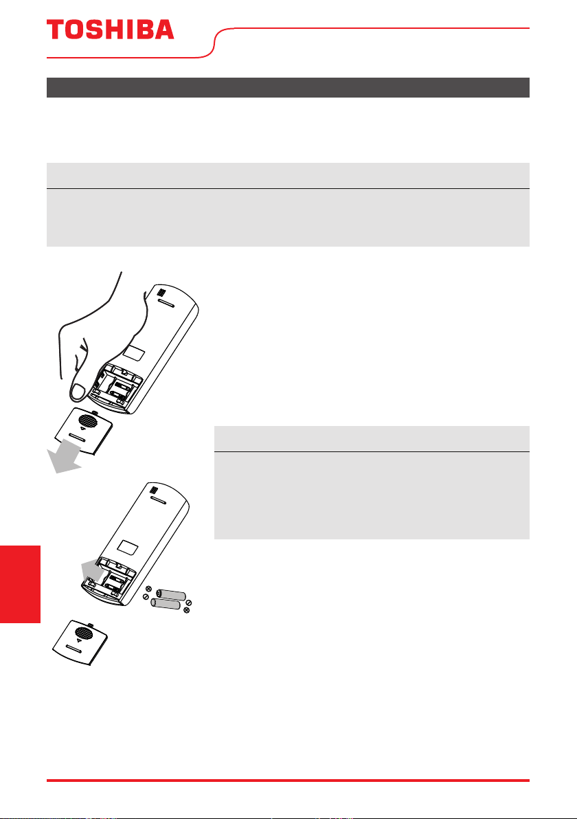
Page 52 User Manual
Manejo del Control Remoto
¿NO ESTÁ SEGURO DE ALGUNA FUNCIONALIDAD?
Consulte la sección Instrucciones de Funcionamiento de este manual para obtener una descripción
detallada de las funciones disponibles en el uso del control remoto.
AVISO
Los diseños de los botones de su unidad pueden diferir ligeramente del ejemplo enseñado.
Si la unidad no tiene una función específica, el uso del botón de esa función en el control remoto
no tendrá ningún efecto.
INSERCIÓN Y SUSTITUCIÓN DE BATERÍAS
Su acondicionador de aire viene con dos baterías (pilas) AAA. Inserte
las baterías en el control remoto antes de usarlo.
1. Deslice la tapa posterior del control remoto hacia abajo,
exponiendo el compartimiento de la batería.
2. Inserte las baterías, prestando atención a alinear los
extremos (+) y (-) de las baterías con los símbolos dentro del
compartimiento.
3. Deslice la tapa de la batería de nuevo a su lugar.
ELIMINACIÓN DE BATERÍAS
Asegúrese de que las baterías usadas sean desechadas correctamente.
CONSEJOS PARA USAR EL CONTROL REMOTO
• El control remoto debe utilizarse a menos de 26 pies / 8 metros
de la unidad.
• La unidad emite un pitido cuando recibe una señal del control
remoto. Cortinas, otros materiales y una luz solar directa
pueden interferir en el receptor de la señal IR.
• Para transmitir correctamente un mando, el indicador ON/OFF
debe iluminarse en la pantalla del control remoto. (Consulte
la sección Indicadores de la pantalla LED del Control Remoto
para obtener más información).
AVISO SOBRE LA BATERÍA
Para un mejor rendimiento del producto:
• No mezcle baterías viejas y nuevas, ni baterías de diferentes
tipos.
• No deje las baterías en el control remoto si no planea utilizar
el dispositivo durante más de 2 meses.
Instrucciones
del control remoto
y del App
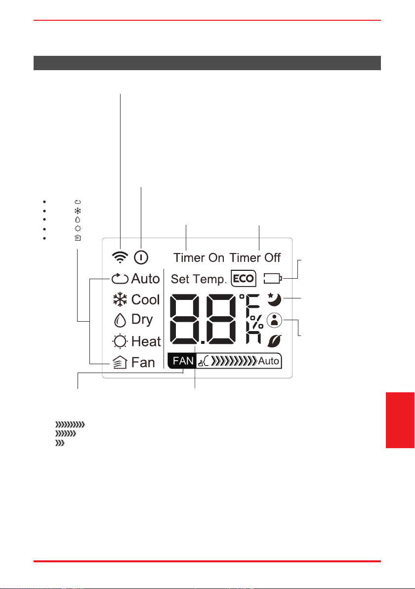
User Manual Page 53
AUTO
COOL
DRY
HEAT
FAN
Indicador de Transmisión
Enciende cuando el control remoto envía una señal a la unidad
Indicador del MODE
Muestra el modo actual,
incluso:
Indicador del TIMER ON
Aparece cuando TIMER
ON está configurado
Indicador del TIMER OFF
Aparece cuando TIMER OFF
está configurado
Indicador de Batería
Detección de que la
batería esté baja
Indicador del SLEEP
Indica que la función
SLEEP está activada
Indicador del FAN SPEED
Muestra la VELOCIDAD DEL
VENTILADOR seleccionada:
HIGH
MED
LOW
Esta parte del visor quedará
en blanco cuando se
establece la velocidad AUTO.
Indicador de la Temperatura y del Timer
Muestra la temperatura configurada o la configuración
del temporizador cuando se utilizan las funciones TIMER
ON / OFF:
- Faja de Temperatura: 62°F-86°F (17°C-30°C)
- Faja de Configuración del Timer: 0-24 horas
Esta parte del visor quedará en blanco cuando el modo
de funcionamiento selecionado for ventilación (FAN).
Indicador de ON/OFF
Aparece cuando el control remoto está habilitado y puede enviar una
señal a la unidad. Si desea apagar el control remoto sin afectar la
unidad, apunte el control remoto lejos de la unidad y presione el botón
ON / OFF.
Para encender el control remoto, apuntelo lejos de la unidad y presione
el botón ON / OFF.
La unidad no recibirá los mandos del control remoto si este indicador
no está iluminado.
Indicador del
MyTemp
Indica que la función
MyTemp está
activada
Indicadores de la pantalla de LEDs del Control Remoto
Instrucciones
del control remoto
y del App
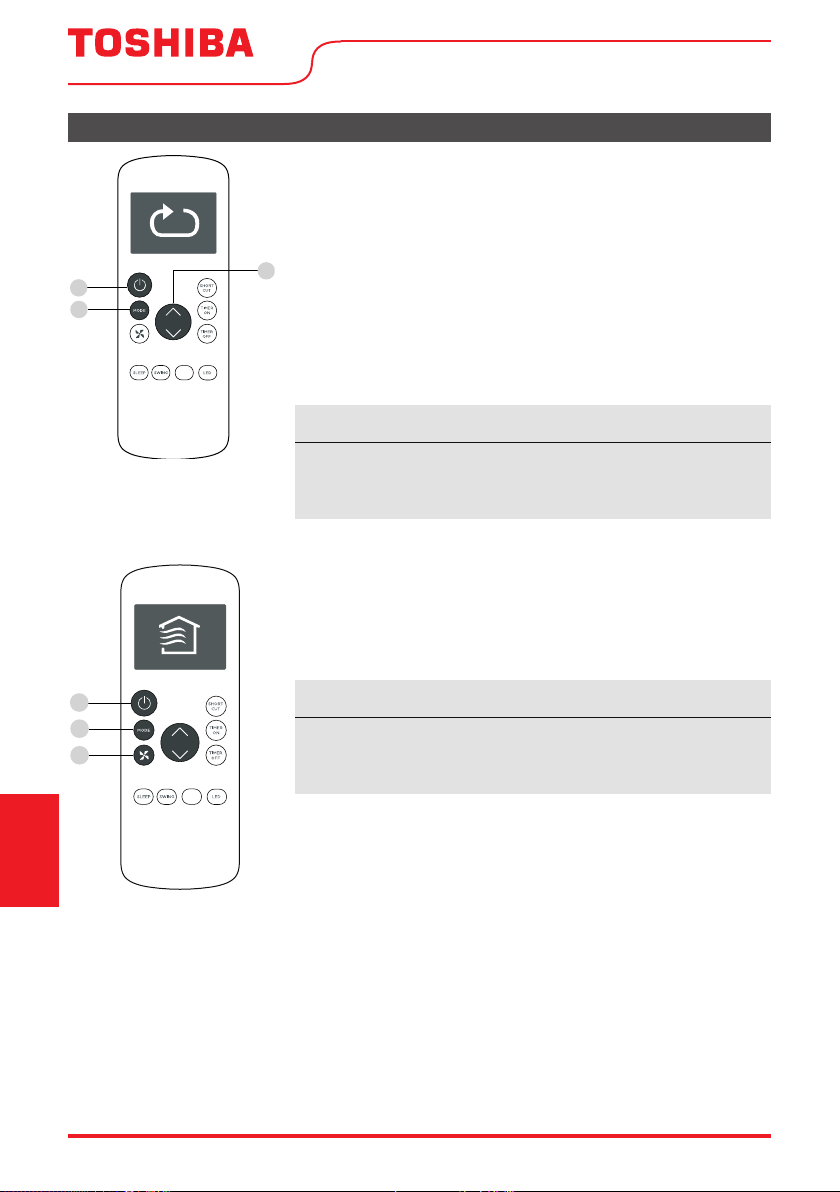
Page 54 User Manual
Funciones Básicas
AJUSTANDO LA TEMPERATURA DESEADA
El alcanze de la conguración de temperatura de esta unidad es
de 62°F a 86°F (17°C - 30°C). Se puede aumentar o disminuir la
temperatura ajustada en incrementos de 1°F o 1°C.
Cambiando el Modo
1. Para cambiar el modo de funcionamiento, pulse el botón MODE
hasta que aparezca el modo deseado en la pantalla del control
remoto.
2. Establezca la temperatura deseada.
AVISO
Si la unidad no cambia cuando se pulsa el botón, compruebe
que el indicador ON/OFF esté iluminado. Si no, apunte el control
remoto a la unidad y pulse el botón ON/OFF.
AVISO
Si la unidad no cambia cuando se pulsa el botón, compruebe
que el indicador ON/OFF esté iluminado. Si no, apunte el control
remoto a la unidad y pulse el botón ON/OFF.
Cambiando la Velocidad del Ventilador
Para cambiar la velocidad del ventilador, pulse el botón FAN hasta
que aparezca la velocidad deseada del ventilador en la pantalla del
control remoto.
1
3
2
MyTemp
1
2
3
MyTemp
Instrucciones
del control remoto
y del App
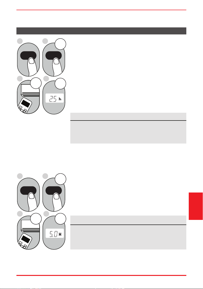
User Manual Page 55
Funciones del Timer
AVISO
Este número indica la cantidad de tiempo después de la hora
actual de la cual desea que la unidad se encienda.
Por ejemplo, si establece TIMER ON durante 2 horas, aparecerá
“2.0h” en la pantalla y la unidad se encenderá después de 2 horas.
Su acondicionador de aire tiene dos funciones relacionadas con el
temporizador:
TIMER ON - configuración del la hora después de la cual la unidad se
encenderá automáticamente.
TIMER OFF - configuración del la hora después de la cual la unidad
se apagará automáticamente.
Configuración del TIMER ON
La función TIMER ON le permite establecer un período de tiempo
después de la cual la unidad se encenderá automáticamente, como
cuando vuelva del trabajo a casa.
1. Pulse el botón TIMER ON. De forma predeterminada, el último
período de tiempo que ha establecido, junto a una letra “h”
(indicando horas) aparecerán en la pantalla.
2s e c
ON/OFF
MODE
FAN
SHORT
CUT
TIMER ON
TIMER OF
F
TEMP
S
L
E
EP
1sec
x5
1
3
2
4
TIMER ON TIMER ON
Ejemplo: con gurar la unidad
para que se encienda después
de 2,5 horas.
2. Pulse el botón TIMER ON repetidamente para ajustar la hora de la
cual desea que se encienda la unidad.
3. Espere 2 segundos y se activará la función TIMER ON. El indicador
digital del control remoto volverá al indicador de temperatura.
2sec
x10
ON/OFF
MODE
F
AN
SHORT
CUT
TIMER ON
TIMER OF
F
TEMP
S
LEEP
1sec
1
3
2
4
TIMER OFF TIMER OFF
Ejemplo: Con gurar la unidad
para que se apague después
de 5 horas.
Configuración del TIMER OFF
La función TIMER OFF le permite establecer un período de tiempo
después de la cual la unidad se encenderá automáticamente, como
cuando se despierta.
1. Pulse el botón TIMER OFF. De forma predeterminada, el último
período de tiempo que ha establecido, junto a una letra “h”
(indicando horas) aparecerán en la pantalla.
2. Pulse el botón TIMER OFF repetidamente para ajustar la hora de la
cual desea que se apague la unidad.
Este número indica la cantidad de tiempo después de la hora
actual de la cual desea que la unidad se apague.
Por ejemplo, si establece TIMER OFF durante 2 horas, aparecerá
“2.0h” en la pantalla y la unidad se apagará después de 2 horas.
AVISO
Instrucciones
del control remoto
y del App
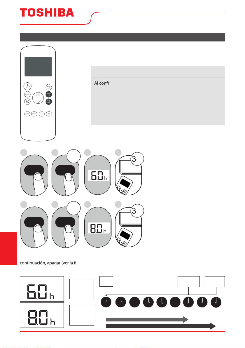
Page 56 User Manual
Continúe
presionando
TIMER ON o
TIMER OFF
hasta
alcanzar
el tiempo
deseado.
Funciones del Timer (cont.)
3. Espere 2 segundos y se activará la función TIMER OFF. El
indicador digital del control remoto volverá al indicador de
temperatura.
AVISO
gurar las funciones TIMER ON o TIMER OFF, hasta 10 horas,
el tiempo aumentará en incrementos de 30 minutos en cada vez
que presiona el botón. Después de 10 horas y hasta 24 horas,
aumentará en incrementos de 1 hora. El temporizador volverá a
cero después de 24 horas.
Puede desactivar cualquiera de las funciones ajustando el
temporizador a “0.0h”.
ON/OFF
MODE
SHORT
CUT
TIMER ON
TEMP
sec
4
ON/OFF
MODE
SHORT
CUT
TIMER ON
TEMP
sec
8
1
TIMER ON
X12
2
TIMER ON
5
TIMER OFF
X16
6
TIMER OFF
3
7
Ajustando las funciones TIMER
ON y TIMER OFF al mismo
tiempo
Tenga en cuenta que los períodos
de tiempo establecidos para
ambas funciones hacen referencia
a horas después de la hora actual.
Por ejemplo, supongamos que
la hora actual es 1:00 PM, y
desea que la unidad se encenda
automáticamente a las 7:00 PM
y desea que funcione durante 2
horas, luego la unidad se apagará
automáticamente a las 9:00 PM.
Siga el ejemplo al lado:
Ejemplo: Ajustando la unidad para que se encienda después de 6 horas, operar durante 2 horas, a
gura a continuación).
La pantalla del control remote mostra:
T i m e r o n
MyTemp
Timer On
Timer O
El temporizador
está configurado
para encenderse
6 horas desde la
hora actual
El temporizador
está configurado
para apagarse a
8 horas de la
hora actual
Hora
Actual 1PM
2PM 3PM
4PM 5PM
6PM 7PM 8PM 9PM
La Unidad
Enciende (ON)
La Unidad
Apaga (OFF)
6 horas después
8 horas despues
Timer
Empieza
Instrucciones
del control remoto
y del App
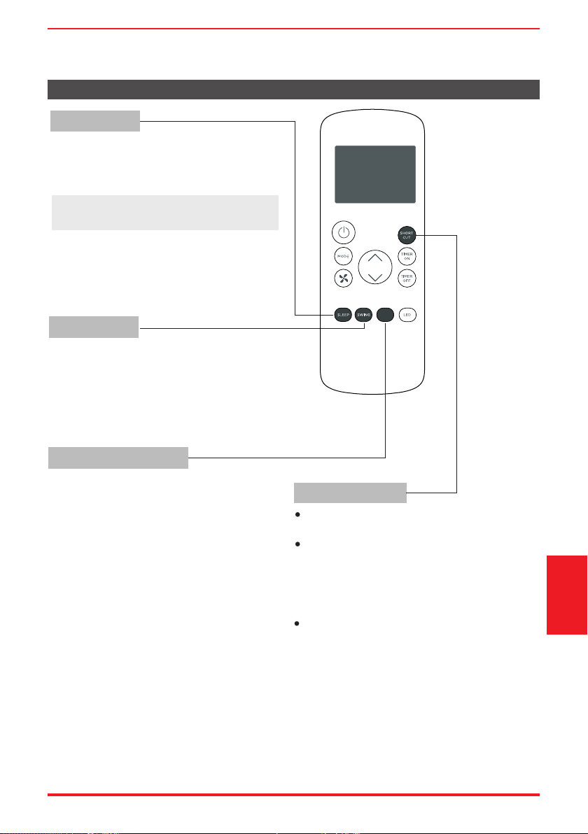
User Manual Page 57
Cómo utilizar las funciones avanzadas
Función SHORTCUT
Función SWING
Función MyTemp
Función SLEEP
La función SLEEP es usada para ahorar energía
mientras del sueño (y no necesita los ajustes
de temperatura para mantenerse cómodo).
Se utiliza para detener o iniciar el movimiento del
deflector y establecer la dirección de flujo de aire
ascendente/descendente deseada. El ángulo del
deflector cambia en incrementos de 6 grados con
cada pulso en el botón (no en todos los modelos).
Pulse durante más de 2 segundos para activar la
función de oscilación automática del deflector.
La función MyTemp permite al control
remoto medir la temperatura en su ubicación
actual.
Mientras de usar las funciones AUTO, COOL o
HEAT, la función MyTemp mide la hace la
medición de la temperatura ambiente desde
el control remoto (en lugar de desde el interior
de la unidad) permitirá que el aparato
optimice la temperatura a su alrededor y
garantice el máximo confort.
1. Pulse el botón MyTemp para activar la función.
El control remoto enviará una señal de
temperatura a la unidad cada tres minutos.
2.
Pulse
el botón MyTemp nuevamente para
desactivar esta función.
Se utiliza para restaurar la configuración actual
o reanudar la configuración anterior.
Pulse este botón cuando el control remoto esté
encendido, el sistema volverá automáticamente
a la configuración anterior, incluido el modo de
funcionamiento, la temperatura de ajuste, el
nivel de velocidad del ventilador y la función
de suspensión (si está activada).
Al pulsar durante más de 2 segundos, el sistema
almacenará automáticamente la configuración
de funcionamiento actual, incluido el modo de
funcionamiento, la temperatura de ajuste, el
nivel de velocidad del ventilador y la función
de suspensión (si está activada).
Nota: La función SLEEP no está disponible
en modo FAN o DRY
MyTemp
Instrucciones
del control remoto
y del App
Page 58 User Manual
Instrucciones
del control remoto
y del App
Declaramos que este Acondicionador de Aire cumple los requisitos esenciales y otras disposiciones
pertinentes de la Directiva 1999/5/CE.
1. Soporte para los sistemas operativos: iOS 7+ o Android 4+..
2. En el caso de una actualización del sistema operativo, puede haber un retraso entre la actualización
del sistema operativo y una actualización de software durante la cual su sistema operativo puede
co o
problemas en su red pueden impedir que el sistema funcione y Toshiba no será responsable de
ningún problema que pueda ser causado por incompatibilidad o problemas de red.
DECLARACIÓN DE CONFORMIDAD
ESPECIFICACIÓN DEL MÓDULO INALÁMBRICO
PRECAUCIONES
Modelo: US-SK105 Dimensiones: 41 x 24 x 5 (mm)
Estándar: IEEE 802.11 b/g/n
Temperatura de funcionamiento: 0°C ~ 45°C /
32°F ~ 113°F.
Tipo de antena: Antena PCB impresa
Banda de frecuencia: 2400-2483.5MHz Humedad de funcionamiento: 10% ~ 85%
Potencia máxima transmitida: <20 dBm Max Entrada de potencia: DC 5V/300 mA
• El diseño del botón se basa en un modelo típico y puede variar ligeramente del real que
compró.
• Este dispositivo cumple con laparte 15 de las Reglas de la FCC. El funcionamiento está
sujeto a las dos condiciones siguientes: (1) Este dispositivo no puede causar interferencias
perjudiciales, y (2) este dispositivo debe aceptar cualquier interferencia recibida, incluidas
las interferencias que puedan causar un funcionamiento no deseado.
• Este equipo ha sido probado y se encontró que cumple con los límites para un dispositivo
digital de Clase B, de acuerdo con la parte 15 de las Reglas de la FCC. Estos límites están
diseñados para proporcionar una protección razonable contra interferencias dañinas en
una instalación residencial. Este equipo genera, usa y puede irradiar energía de
radiofrecuencia y, si no se instala y usa de acuerdo con las instrucciones, puede causar
interferencia dañina a las comunicaciones de radio. Sin embargo, no hay garantía de que
la interferencia no ocurra en una instalación en particular. Si este equipo causa
interferencias perjudiciales para la recepción de radio o televisión, lo cual puede
determinarse encendiendo y apagando el equipo, se recomienda al usuario que intente
corregir la interferencia mediante una o más de las siguientes medidas:
- Reorientar o reubicar la antena receptora.
- Aumente la separación entre el equipo y el receptor.
- Conecte el equipo a una toma de corriente en un circuito diferente al que está conectado
el receptor.
- Consulte con el distribuidor o un técnico experimentado en radio / TV para obtener ayuda.
- Los cambios o modicaciones no aprobados por la parte responsable del cumplimiento
pueden anular la autoridad de los usuarios para operar el equipo.
AVISO
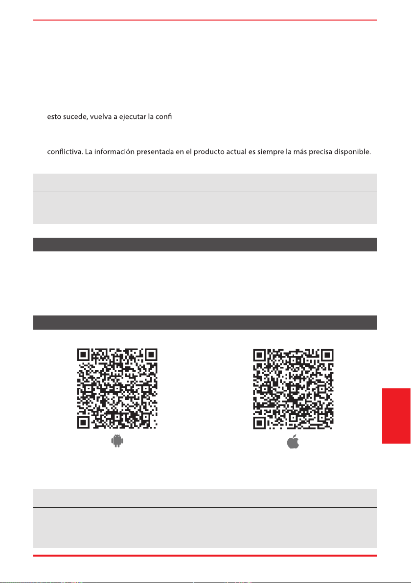
User Manual Page 59
Instrucciones
del control remoto
y del App
Dispositivos necesarios para utilizar el Acondicionador de aire inteligente:
1. Smartphone con sistema iOS o Android compatible.
2. Router inalámbrico (se requiere una red de 2.4GHz para conectarse)
3. Acondicionador de aire Inteligente
VISIÓN GENERAL DEL SISTEMA
DESCARGAR E INSTALAR LA APLICACIÓN
Código QR de AppleCódigo QR de Android
Escanear para descargar la aplicación.
• También puede ir a Google Play o App Store y buscar Toshiba NA AC. Para obtener más
información, consulte la página web de Toshiba Lifestyle: www.toshiba-lifestyle.com
Todas las imágenes de este manual son solo para referencia, su producto y aplicación pueden tener
un aspecto ligeramente diferente. Las instrucciones reales del producto y de la aplicación deben ser
consideradas.
AVISO
3. Este acondicionador de aire inteligente solo permite el cifrado WPA-PSK/WPA2-PSK (recomendado).
Consulte la dirección web de Toshiba Lifestyle, www.toshiba-lifestyle.com, para obtener informaciónes
actualizadas.
4. Para garantizar el escaneo adecuado del código QR, su smart phone debe tener al menos una
cámara de 5 megapíxeles.
5. Debido a la conectividad de red inestable, las solicitudes pueden agotar el
tiempo de espera. Si
guración de red.
6. Debido a la conectividad de red inestable, los comandos pueden agotar el tiempo de espera. Si
esto sucede, la aplicación del Smartphone y el producto actual pueden presentar información
Actualice la aplicación para volver a sincronizarla
Toshiba no será responsable de ningún problema que pueda ser causado por incompatibilidad o
problemas de red, su router inalámbrico y teléfono móvil.
AVISO
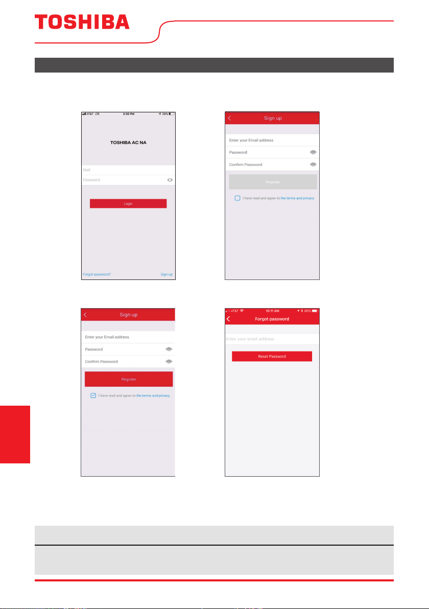
Page 60 User Manual
CREA TU CUENTA
• Asegúrese de que su Smartphone esté conectado a su router inalámbrico y que su router inalámbrico tenga
una conexión a Internet de 2,4 GHz.
• Se recomienda activar su cuenta inmediatamente para poder recuperar su contraseña por correo electrónico.
6.1 Pulse “Registrarse”.
6.2 Introduzca su dirección de correo
electrónico y contraseña.
6.3 Pulse “Registro”.
6.4 En caso de que olvide su contraseña, pulse
“¿Olvidó su contraseña?” en el menú principal e
introduzca su dirección de correo electrónico.
A continuación, pulse “Restablecer contraseña”.
• Asegúrese de que su Smartphone es capaz de conectarse a la red inalámbrica que se utilizará.
• Asegúrese también de que el dispositivo no se está conectando a otras redes al alcance.
AVISO
Instrucciones
del control remoto
y del App
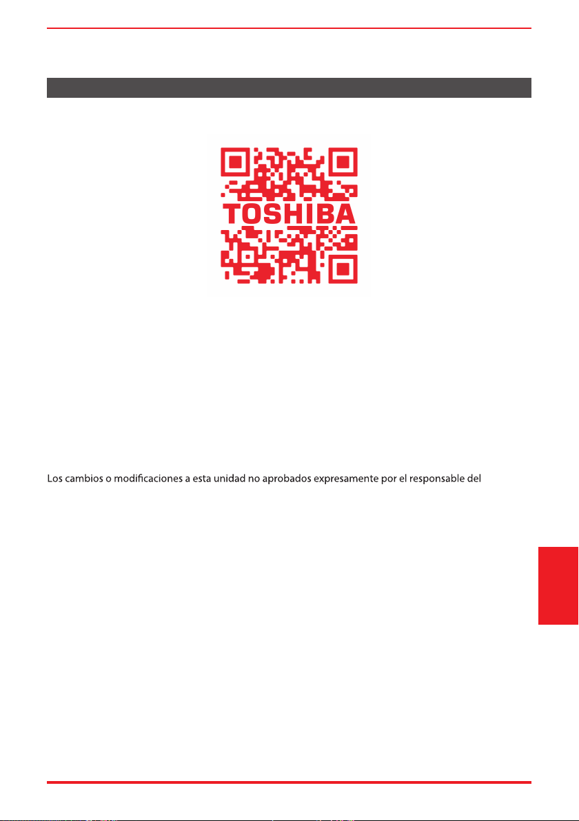
User Manual Page 61
FUNCIONES ADICIONALES DE LA APLICACIÓN Y SMART HOME
Para obtener instrucciones adicionales sobre las características de la aplicación y las capacidades del
sistema Smart Home, escanee el código QR a continuación
Instrucciones
del control remoto
y del App
Este dispositivo cumple con la Parte 15 de las Reglas FCC y contiene transmisores/ receptores libres de
licencia que cumplen con los RSS de Innovación, Ciencia y Desarrollo Económico de Canadá que no
exigen la licencia.
El funcionamiento está sujeto a las dos condiciones siguientes:
(1) Este dispositivo podría no causar interferencia; y
(2) Este dispositivo debe aceptar cualquier interferencia, incluida la interferencia que pueda causar un
funcionamiento no deseado del dispositivo.
Declaración de conformidad
CONTIENE FCC ID: 2ADQOMDNA21
CONTIENE IC: 12575A-MDNA21
La compañía no será responsable de cualquier problema causado por el internet, el
enrutador Wi-Fi / inalámbrico o los dispositivos inteligentes. Póngase en contacto
con el proveedor original para obtener más ayuda.
NOTA: Este equipo ha sido probado y se ha comprobado que cumple con los límites para un dispositivo
digital de clase B, de conformidad con la parte 15 de las Reglas de FCC. Estos límites están diseñados para
proporcionar una protección razonable contra interferencias dañinas en una instalación residencial. Este
equipo genera, utiliza y puede irradiar energía de radiofrecuencia y, si no se instala y utiliza de acuerdo
con las instrucciones, puede causar interferencias dañinas a las comunicaciones radioeléctricas. Sin
embargo, no hay garantía de que no se produzcan interferencias en una instalación particular. Si
este equipo causa interferencias perjudiciales en la recepción de radio o televisión, que se pueden
determinar apagando y encendiendo el equipo, se recomienda al usuario que intente corregir la
interferencia mediante una o más de las siguientes medidas:
-- Reoriente o reubique la antena receptora.
-- Aumente la separación entre el equipo y el receptor.
-- Conecte el equipo a un enchufe en un circuito diferente al que está conectado el receptor.
-- Consulte al distribuidor o a un técnico de radio/TV con experiencia para obtener ayuda.
Utilice el dispositivo únicamente de acuerdo con las instrucciones suministradas.
cumplimiento podrían anular la autoridad del usuario para operar el equipo. Este dispositivo cumple
con los límites de exposición a la radiación FCC establecidos para un entorno no controlado. Para evitar
la posibilidad de superar los límites de exposición a radiofrecuencia FCC, la proximidad humana a la
antena no deberá ser inferior a 20 cm (8 pulgadas) durante el funcionamiento normal.

Declaración de conformidad del proveedor
47 CFR § 2.1077 Información sobre el cumplimiento
Identificador único:RG57H4(B)/BGEFU1
Parte responsable Información de contacto de los Estados Unidos
Midea America Corporation
300 Kimball Dr
Parsippany NJ
07054
Este dispositivo cumple con la Parte 15 de las Normas de la FCC. La operación
está sujeta a las siguientes dos condiciones: (1)Este dispositivo no puede
causar interferencias perjudiciales,y (2)este dispositivo debe aceptar
cualquier interferencia recibida, incluida la interferencia que pueda provocar
un funcionamiento no deseado.
Número de teléfono o información de contacto en Internet:Midea.com/us
Declaración de cumplimiento de la FCC
(productos sujetos a la Parte 15)