
The installation of this product must be carried out by a qualified professional.
Instruction manual
01
Index
Introduction
Please read this manual carefully before connecting or using the product. In case of doubts,
please contact our technical support: (18) 3266-4050 or www.taramps.com.br.
Congratulations on purchasing AMPLAYER G2!
The AMPLAYER G2 stands out not only for its performance, but also for its appearance. Its
innovative design is complemented by a front lighting system with seven vibrant colors,
allowing you to customize your car’s ambience.
Power and style for your vehicle. The AMPLAYER G2 is not only a car player, it is an integrated
entertainment system that combines power, technology, innovative design, and versatility.
This product includes a remote control, player, amplifier, and an RGB control module for LED
strips or strobe lighting.
With 4 amplified channels of 100 Watts RMS, the AMPLAYER G2 delivers a sound quality.
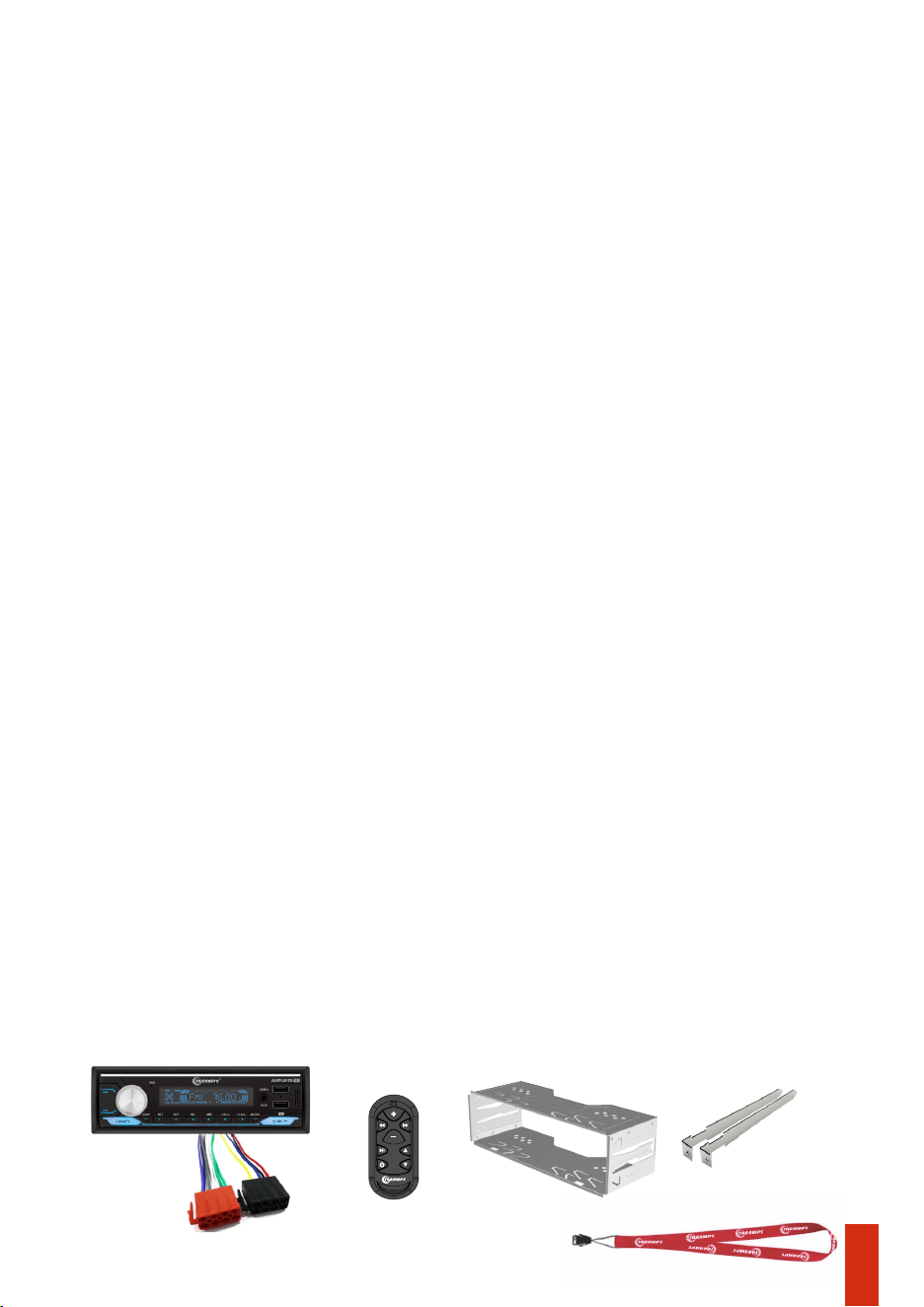
Package contents
• 01 Remote
control
• 02 Removal Key• 01 Metal installation frame • 01 AMPLAYER
• 02 Wiring
Harness
• 01 Taramps brand cord
02 • Safety Requirements
• Package Contents
01 • Introduction
• Safety
03 • Panel functions
• Important Recommendations
09 • Car dashboard installation
07 • Remote control functions
04 / 05 / 06 • Panel functions (Cont’d)
08 • Output and power connector
• AMPLAYER cleaning
13 • Technical specications
• Bridge connection example
12 • Bluetooth
• SYNC another remote control
• Recommended wire gauge and fuse
11 • Stereo connection example
10 •Installation
• Head unit
• Remote control
15 • Warranty terms
14 • Declaration on conformity
• Technical assistance
• FCC Warning

Safety precautions
Safety
Throughout this manual, pay attention to the safety symbols.
Taramps reserves the right to modify the contents of this manual without prior notice and without any
obligation to apply such modications to units previously manufactured.
This symbol as ‘’Caution’’ is intended to alert the user to important instructions.
Failure to follow the instructions may result in risks to the user or damage to the
product.
Caution
As protection, a fuse (20A) must be installed near the positive terminal of the battery. See more
details on page 10 of this manual.
This product incorporates a high power Class D amplifier, which may degrade the reception of
distant FM stations. To achieve the best FM reception, avoid routing the antenna cable
together with the product’s installation wiring.
The recommended wire gauge is 4mm² for the positive/negative wires and 0,75mm² for the
remote and ACC wire.
LED strips may also interfere with radio, depending on the lighting effect, the chosen color, or
the installation location.
Important information
02
- Make sure the AMPLAYER is turned OFF before proceeding with any connection or
disconnection of its connectors.
- Make sure to install a protective fuse or circuit breaker near the battery. Follow the amperage
specified in this manual. Using an incorrect fuse or circuit breaker may result in overheating,
smoke, product damage, injury, or burns.
- If you wish to dispose of this product, do not throw it in household waste. It must be collected
by an electronic waste disposal service for proper recycling.
- Never install the AMPLAYER in locations exposed to moisture, or water. Make sure to install it
away from the fuel tank, fuel lines, heat sources, and other parts of the vehicle.
- Avoid routing wires over or through sharp edges. Use rubber or plastic grommets to protect
any wires that pass through the vehicle’s bodywork.
- The installation of this product must be carried out by a qualified professional.
-During use, the external surface may become hot. Avoid touching the heat sink area and keep
children away from the product.
- This product must be used with 12V batteries. Always check the voltage before installation.
- Use safety glasses, insulated gloves, and the proper tools to install this product.
- To ensure proper use, read this manual before using the AMPLAYER. It is important that you
are aware of the PRECAUTIONS contained herein.
- Before making any connection to the AMPLAYER, disconnect the negative (-) terminal of the
battery.
- This product can produce high sound pressure levels. Avoid continuous exposure to levels
above 85dB to prevent hearing loss.
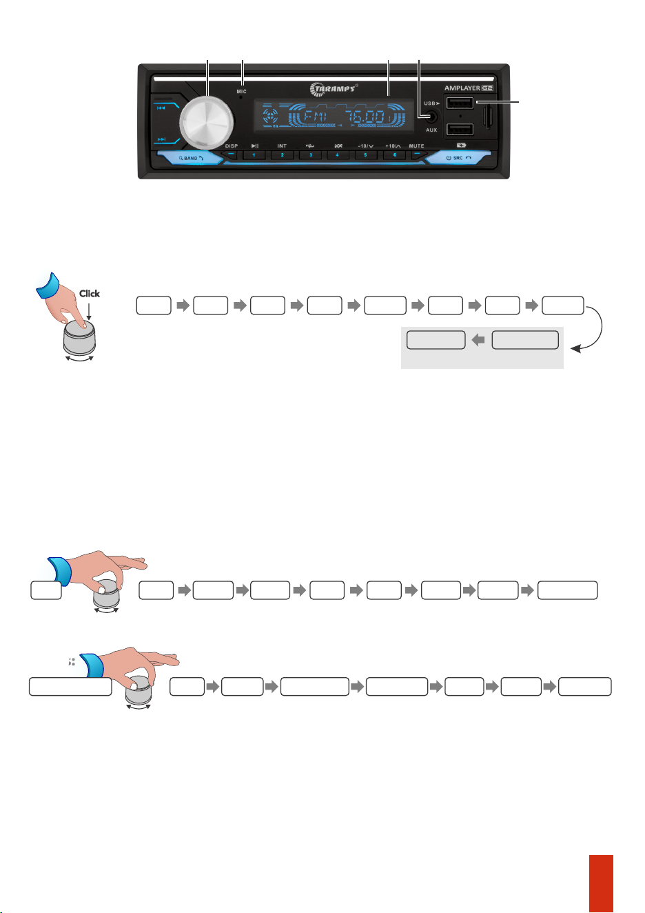
1 - Rotary knob:
Volume: Increases or decreases the audio volume.
Function adjustment: Access the functions by pressing the center of the knob. To adjust a
function, simply rotate the knob to the right or left.
BASS: Bass adjustment, allowing boost or attenuation of up to 7dB;
TRE: Treble adjustment, allowing or attenuation of up to 7dB;
BAL: Balance adjustment, distributes the signals between the left and right channels ;
FAD: Fader adjustment, distributes the signals between the front and rear channels;
LOUD: Activates the loudness function;
Colors:
2 - Mic: Hands free microphone.
3 - LCD Display: Displays FM radio frequency, track/folder number, signal source, song title,
functions...
capacity is 32GB).
DSP: Accesses the 7 band graphic equalizer (60Hz, 250Hz, 500Hz, 1KHz, 2KHz, 10KHz, 15KHz)
with boost or attenuation of up to 7dB.
5 - USB: USB input for connecting a flash drive containing music files (max. recomended
EQ: Provides 6 equalization curves: Flat/Rock/Pop/Classic/Jazz/User (DPS);
4 - Aux: Auxiliary J2 input for connecting another device (Ex.: Smartphones).
Click
03
Panel functions
1 32
5
4
BASS TRE BAL FAD LOUD EQ DSP
LOC / DX
COLORS
MONO / ST
FM RADIO MODE ONLY
*DSP RST: Resets the equalization values to zero.
BLUE GREEN RED
YELLOW
PURPLE
CYAN WHITE
AUTOMÁTICA
60Hz 250Hz 500Hz
1KHz
2KHz
10KHz
15KHz DSP RST *
DSP
Adjustment
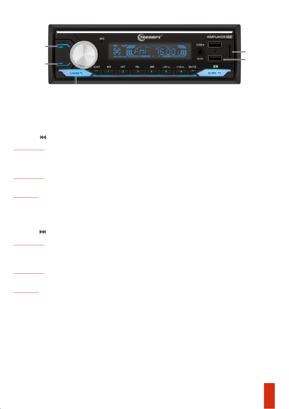
10 - BAND/ANSWER/SEARCH:
USB / SD
Short press: Switch between FM1/FM2/FM3, each option with 6 present stations.
FM RADIO
USB / SD CARD
Long Press: Fast Forward.
BLUETOOTH:
Short Press: Numeric track search function using the rotary encoder.
Short Press: Answers incoming calls, redials the last number.
Long Press: Performs an automatic search and stores the strongest signal stations.
Short Press : Next track.
Short Press : Next track.
USB / SD
Short Press: Previous track.
8 - Track / Tune -:
FM RADIO
Short Press: Previous track.
9 - Track / Tune +:
Short Press: Increases the FM tuning frequency by 0.1MHz.
Bluetooth
7 - Charger: 5V output- max. 1A, dedicated for standard charging only.
Long press: Automatically searches for the previous FM station.
Long Press: Fast rewind.
Long Press: Automatically searches for the next FM station.
FM RADIO
Short Press: Decreases the FM tuning frequency by 0.1MHz.
6 - SD: Micro SD card slot for connecting a memory card containing music files.
Bluetooth
Panel functions (continued)
10
6
8
9
7
04
Panel functions (continued)
11 12 13 14
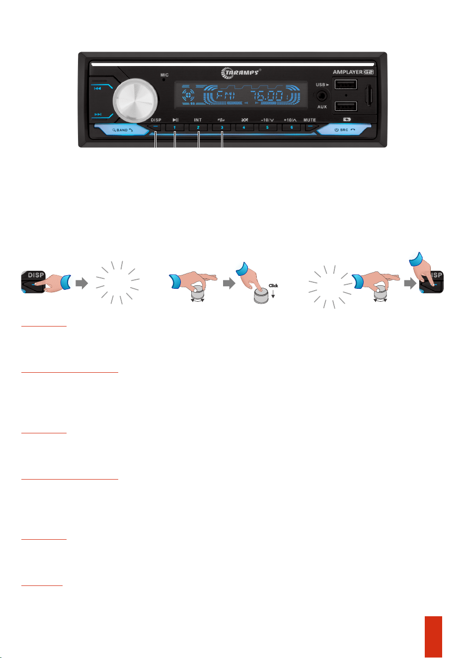
Bluetooth / USB / SD
Long press: Saves the station to position 2.
14 - Repeat / 3:
12 - Play / Pause / 1:
Long press: Saves the station to position 1.
Short press: Play/Pause
Short press: Selects the radio station from memory position 2.
Plays only the first 10 seconds of each track (intro scan).
Long press: Saves the station to position 3.
USB / SD
Short press: One - Track repeat.
All - Repeat all.
Bluetooth / USB / SD
FM Radio
Short press:Selects the radio station from memory position1.
13 - Int / 2:
Folder -Repeat folder.
Short press: Selects the radio station from memory position 3.
FM Radio
FM Radio
11 - DISP: Function to switch between displaying the clock time or displaying playback
information.
Short Press: Switches the display between playback information (track number, track name,
folder name) or clock.
Long Press: Hour/Minute adjustment.
00:00
03:00
Long Press
Long
Press
Adjustment Adjustment
Click
05
06
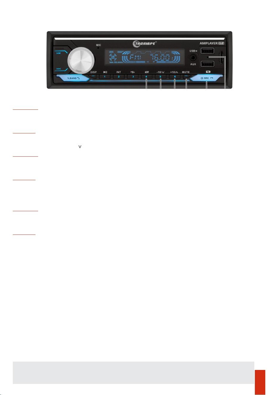
Long press: Saves the station to position 5
16 - Previous folder -10 / / 5:
Long press: Saves the station to position 6
Short press: Enables the random mode playback.
During a phone call: Ends or rejects the call
Short press: Skips forward 10 tracks / Long press: Next folder.
FM Radio
Short press: Selects the radio station from memory position 4.
USB / SD
Long press: Saves the station to position 4.
Short press: Skips back 10 tracks / Long press: Previous folder.
With the AMPLAYER turned off: Short press, turns on the unit
Short press: selects the functions: USB / BLUETOOTH / AUX / FM
FM Radio
15 - Random / 4:
FM Radio
Short press: Selects the radio station from memory position 5.
USB / SD
17 -Next folder +10 / ^ / 6:
Short press: Select the radio station from memory position 6.
USB / SD
18 - Mute : Disables the audio signal.
19 - Source (ON/OFF / Mode / END/ Reject call):
With the AMPLAYER turned on:
Long press: Turns off the unit
20 - Reset: If you want to restore the factory default settings or in case the panel malfunction, insert
a metal tip (ex. an opened paper clip) and press for 2 seconds. After the unit turns off, turn in on
again.
Panel functions (continued)
15 16 17 18 19 20
Store FM stations: To store stations, simply tune to the desired station and press and hold one of the
preset keys (1 to 6). Press BAND to switch between FM1, FM2 and FM3 (18 presets in total).
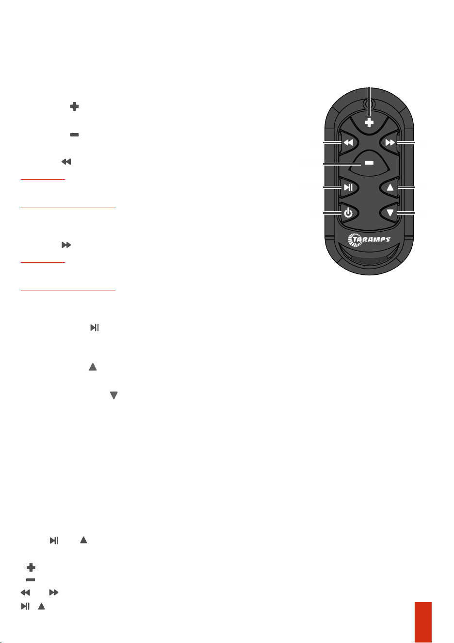
Remote control functions
RGB effects change (via remote control)
4 - Next folder
Bluetooth / USB / SD
Bluetooth / USB / SD
Previous track
4 - Track / Tune :-
2 - Volume : Increases the volume.
Starts or pauses music playback
3 - Volume : Decreases the volume.
Long press: Turn off the AMPLAYER.
FM Radio
FM Radio
Increases the FM tuning frequency by 0.1 MHz
5 - Track / Tune :+
Short press with the unit turned on: Selects the signal sources (USB, BT, FM, AUX)
Decreases the FM tuning frequency by 0.1 MH z
6 - Play / Pause :
1 - Short press with the unit turned off: Turns on the AMPLAYER.
Next track
5 - Previous folder
It is possible to change the programmed effect on the LED strip and RGB strobe outputs using
the remote control, as well as the SYNC button on the rear panel.
- Press and With the product turned on;
and = Switches effect/color type;
- = Light intensity(Increase);
- The front panel illumination will fast flash, indicating the RGB control mode.
Note: The AMPLAYER panel color can only be changed using the volume encoder (page 3).
+ = Returns to audio functions control (The illumination stops flashing).
- = Light intensity(Decrease);
2
1 8
4 5
6
3
7
07
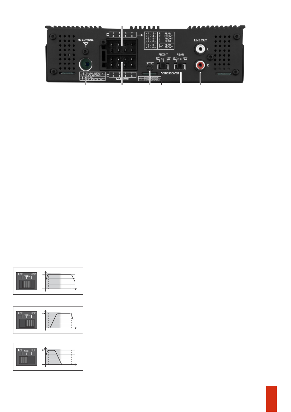
Output and power connector
1 - FM Antenna: FM antenna input.
For connections in STEREO mode, the minimum inpedance is 2 OHMS per channel; in BRIDGE
mode, it is 4 OHMS.
Refer to the wiring diagram on page 11.
Red wire: Ignition switched signal (ACC).
2- Speaker connector.
For speaker associations, the impedance to be considered is the resulting impedance.
3 - Power connector/ REM OUT / RGB OUT: The yellow (+) wires from the connector must be
joined and connected to the positive terminal of the battery using a cable with a minimum
cross section of 4mm². The black (-) wires from the connector must be joined and connected to
the negative terminal of the battery using a cable of equivalent gauge to the positive cable.
Refer to the wiring diagram on page 10.
Blue wire: Output for antenna control or remote latput (for external amplifiers).
Gray wire: Output for controlling RGB strips/LED strobe lights.
7 - LINE OUT: The LINE OUT output allows sending the audio signal (low level) to another device,
such as an amplifier or an active subwoofer.
The signal from this output comes from the REAR channels and is not affected by crossover
4 - SYNC Key: For remote control SYNC (page 12) or RGB effect change.
5 and 6- Crossover Front and Rear
1
3
2
5
4
6
7
Amplifies only sub bass and bass frequencies, as the response is limited to
90Hz (12dB/8ª) the ideal cutoff for subwoofers.
Selector in the position - FULL
Amplifies the entire audio range, responding from 20Hz to 20kHz. This
function is normally used when there is an external crossover in the
system.
Amplifies signals from 90Hz upwards. This type of functions is used for
reproductions in mid bass and midrange speakers. A common example is
two way kits and 6x9 speakers.
Selector in the position - HPF - (HIGH PASS)
Selector in the position - LPF - (LOW PASS)
20KHz90Hz
Audio track
20Hz
20KHz90Hz
Audio track
20Hz
Audio track
20Hz
20KHz
08
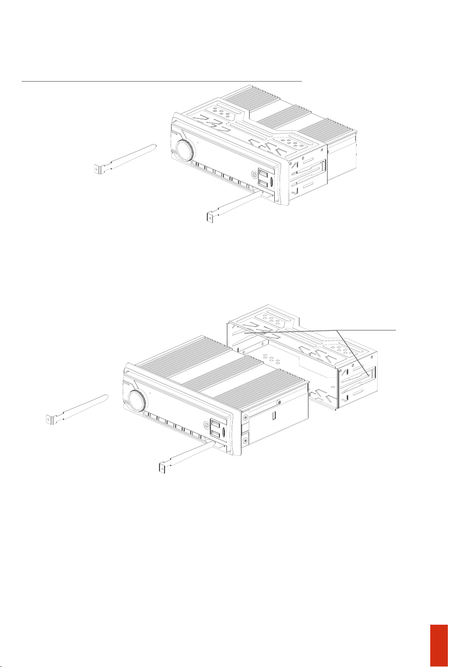
Position the removal keys as shown in the image below to detach the product’s metal bracket.
Remove the painel’s plastic frame to access the key insertion points.
Attention: The front panel of the AMPLAYER is not removable.
Install the metal bracket into the slot provided for the radio in the vehicle’s dashboard and
bend the tabs to properly secure the metal bracket in the installation opening.
The AMPLAYER may not be compatible with other plastic or metal installation brackets. Use the
supplied metal bracket to securely attach the unit to the dashboard.
Never use chemical, abrasive, or cleaning products .
The AMPLAYER panel can be cleaned with a soft cloth to avoid scratches, stains, or damage.
Car dashboard installation
AMPLAYER Cleaning
2 fixing clips
09
Installation
Positive/negative power cable_________________________________________4mm²
ACC Cable____________________________________________________________0,75mm²
Antenna cable / Remote________________________________________________0,75mm²
Protective fuse or circuit breaker______________________________________________20A
*Calculated considering a maximum length of 4m. For longer distances, it will be necessary to
increase the cable gauges.
Recommended wiring gauge and fuse
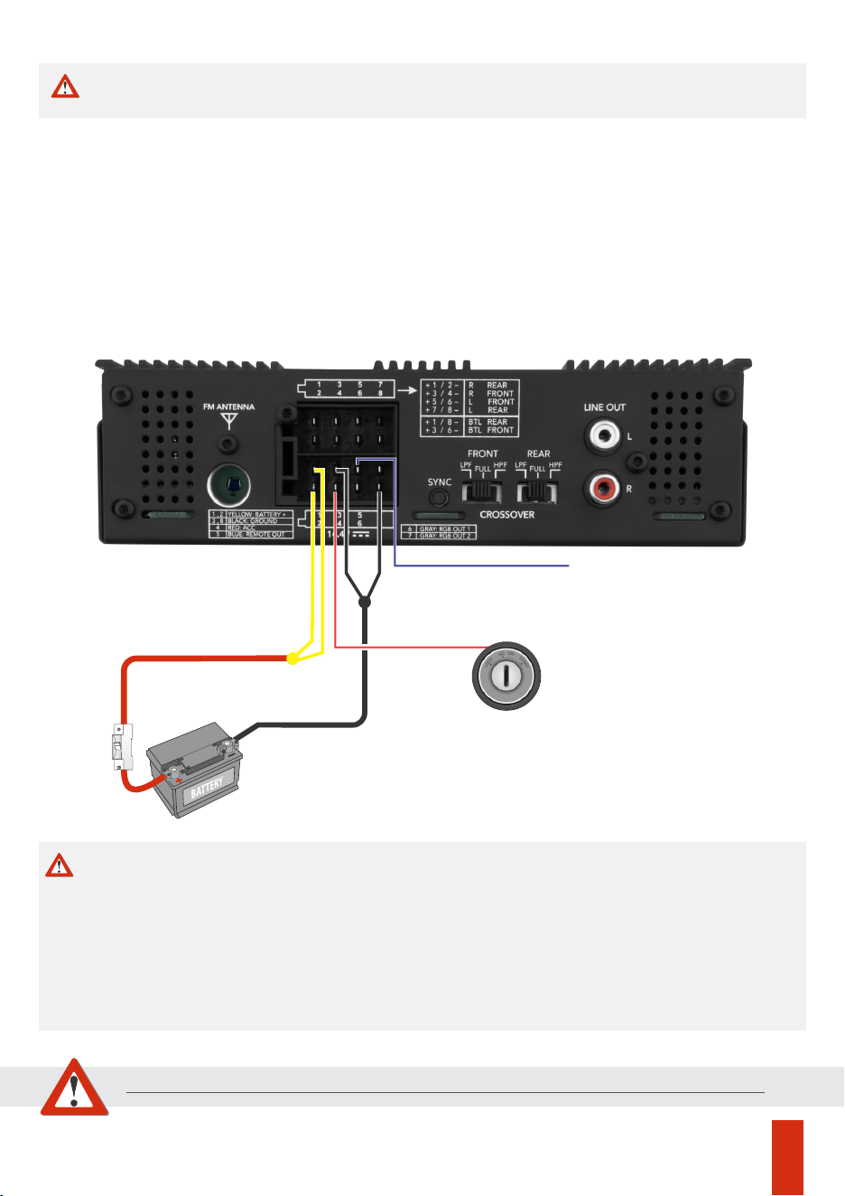
CAUTION
Any connection to the power, input, or output connectors must be made
only with the AMPLAYER turned off.
10
P. Ant / Remote
GND
Wire 4mm²
Yellow
Black
Blue
Red
Wire 4mm²
BATT+ 12VDC
Caution
Before making any connections to the power terminals, make sure the vehicle’s battery
negative (-) terminal is disconnected.
Using wiring with a gauge smaller than recommended causes power loss and overheating of the
wiring.
*It is necessary to join the two yellow wires (Batt+) and join the two black wires (GND).
Do not use the vehicle’s original wiring: Perform a new installation directly from the battery.
The use of a 20A fuse or circuit breaker near the battery is indispensable.
Observe polarity, never reverse the power cables, as this may damage the AMPLAYER.
The installation of this product must be carried out by a qualified professional.
BREAKER
20A
ACC
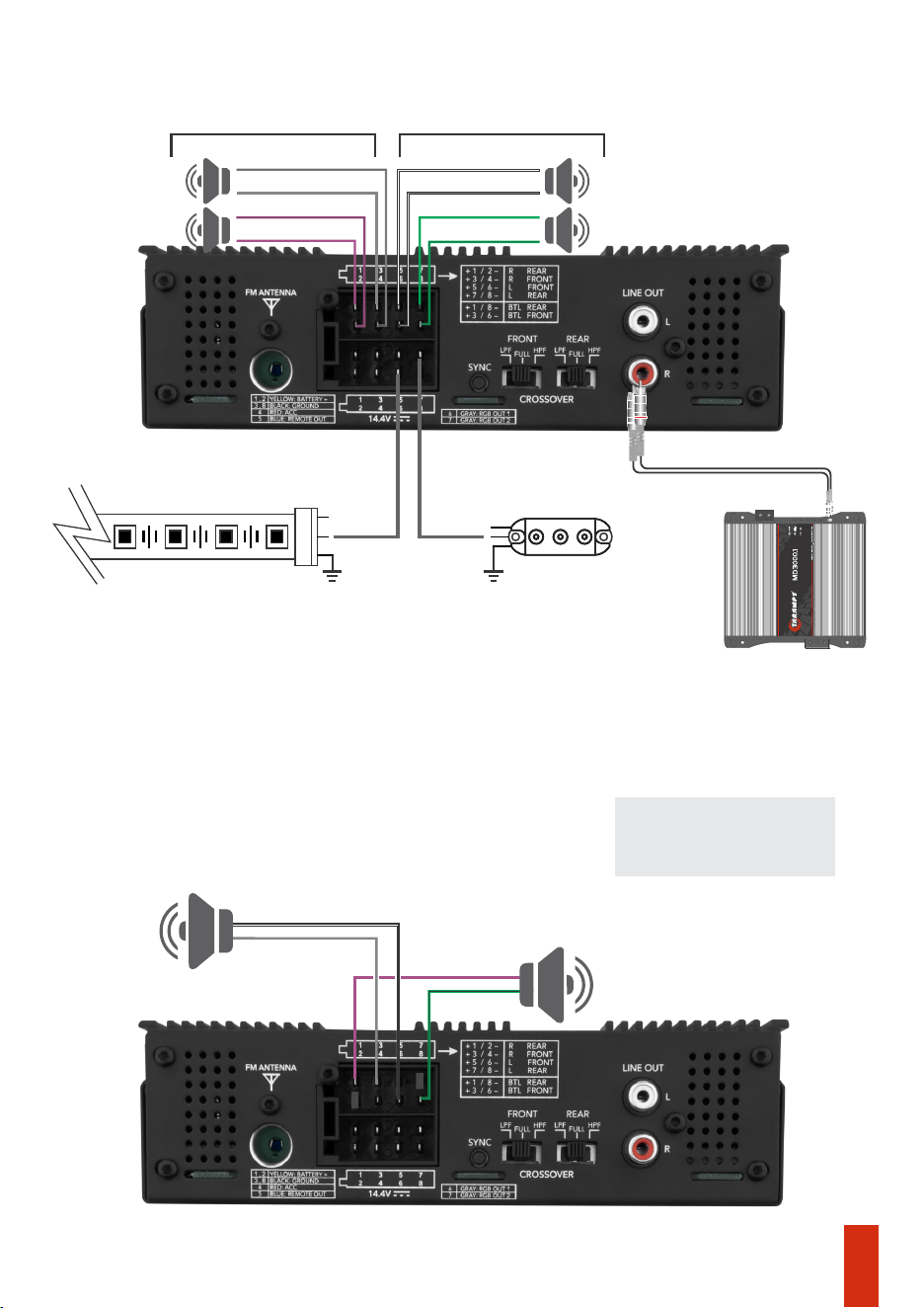
Bridge connection example
4 OHMS per channel (2 channels)
Stereo connection example
2 OHMS per channel (4 channels)
REAR + REAR -
FRONT + FRONT -
REAR - REAR +
FRONT -
(RIGHT) (LEFT)
FRONT +
2
Ω
2
Ω
2
Ω
2
Ω
11
IMPORTANT: Unused
wires must be insulated
REAR +
FRONT +
REAR -
FRONT -
4
Ω
4
Ω
8
8
Subwoofer
Subwoofer
Output for another amplier
(Optional)
WS 2811 LED strips and/or LED strobe lights
By default, the initial lighting effect is GREEN. To change the color, brightness, and
effect type, use the remote control in RGB mode (Page 07) or simply press SYNC at
rear panel.
+12V
DATA DATA
+12V
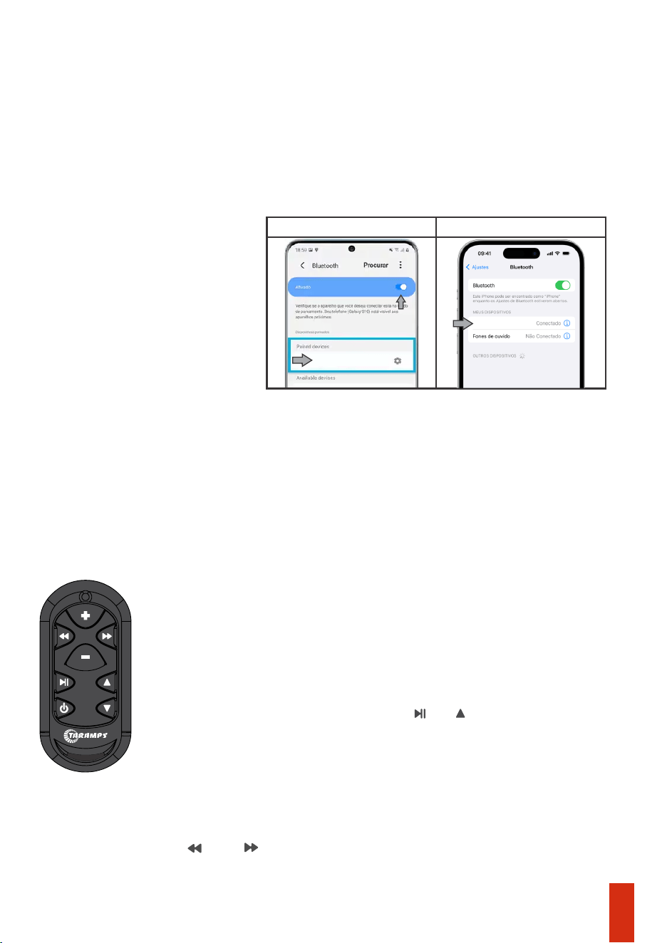
-At any time, even with the AMPLAYER turned off (but with ACC active), it is possible to set up a
connection. Search with your mobile phone and complete the pairing.
-Specication Bluetooth: Class II with an average range of 10m.
- To connect to a new device, disconnect the current one and perform new Bluetooth pairing.
SYNC another remote control
Bluetooth
12
It is possible to use up to 3 remote controls simultaneously.
To synchronize a new remote control, follow the instructions:
Press and simultaneously until the control’s LED turns off. Check the
number of LED flashes: 3 flashes= OOK/ASK / 4flashes= FSK
4- On the remote control, press the keys and . The panel stops flashing.
(Check if the remote control is compatible)
1- Turn on the AMPLAYER.
3- The panel illumination will start flashing.
The new remote control must be TARAMPS brand, configured for FSK
modulation. To switch between modulation types, follow the procedure below:
2- Press and hold the SYNC button on the rear panel for 5 seconds.
For other devices, the connection procedure is similar (refer to the manufacturer’s manual).
Android
IOS
AMPLAYER_G2
AMPLAYER_G2

Technical specifications
Taramps reserves the right to modify the contents of this manual without prior notice and without any
obligation to apply such modications to units previously manufactured.
**Frequency response measured at 2 times the minimum impedance, in 4 channel mode.
*Rated power at 14.4VDC, 1KHz sinusoidal signal and THD < 10%.
***The values as above are typical and may vary, due to electronic components tolerance or manufacturing process.
FM frequency range:
Number of channels:
Rated power @ 14.4VDC - 4 Ohms:
2 Bridged Channel - 4 Ohms:
Model:
Output capacity RGB:
Formats and capacity (USB - SD):
Auxiliary output RCA:
Maximum power consumption:
Power consumption on, without audio:
Bluetooth version:
Signals sources:
LPF (Low pass filter):
Power stand-by (ACC ON):
Minimum supply voltage:
Rated power @ 14.4VDC - 2 Ohms:
Frequency response (Full Range):
Signal to Noise Ratio:
Cap. USB port (recharge):
Crossover
HPF (High pass filter):
Protection system:
Maximum supply voltage
Memory usage (ACC):
Weight:
Musical power consumption:
Installation space:
Dimensions (L x A x P):
240W RMS (4 x 60W RMS)
Standard Charging 1A max.
400W RMS (2 x 200W RMS)*
USB,SD,FM,Bluetooth,AUX.
MP3,WMA,APE e FLAC - 32Gb Max.
04
400W RMS (4 x 100W RMS)*
V. 5.3
76 a 108MHz, 18 memórias
Amplayer 400 G2
2V RMS
>85dB
20Hz a 20KHz (-3dB)**
90Hz (-12dB/8ª) Fixed
16VDC
0.85A
90Hz (-12dB/8ª) Fixed
30mA
18.5A
25mA
9VDC
Output short circuit
37A
1 DIN - ISO7736:1984
188 x 58 x 152mm
1Kg
LED STRIP:up to 8.5meters(30 LEDS/m) or 4,25meters (60 LEDS/m)
LED STROBE= up to 85 units
13
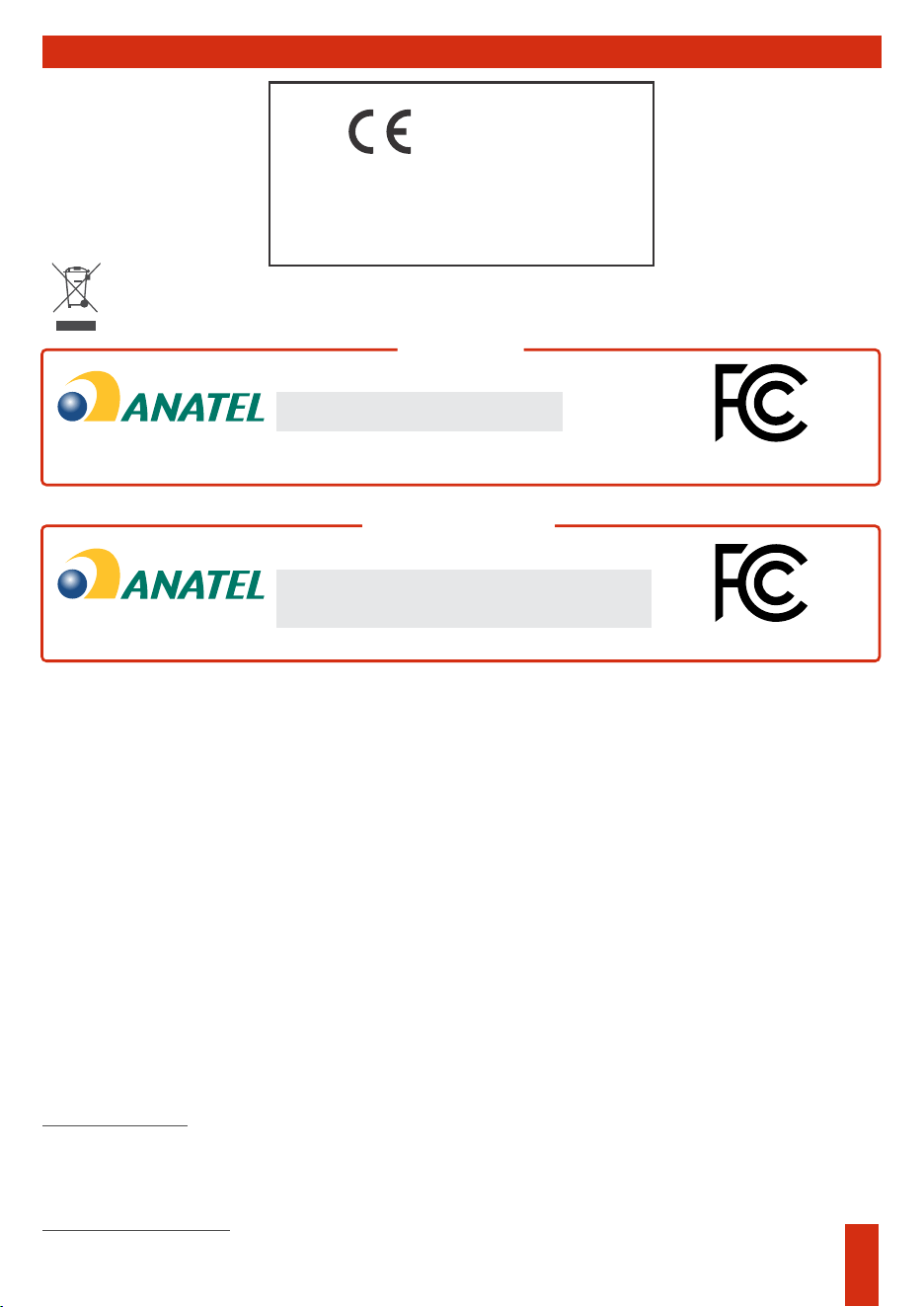
Declaration of conformity
TARAMPS ELECTRONICS LTDA
Alfredo Marcondes - SP
Brasil
It is hereby declared that the AMPLAYER G2 product is in conformity with
directive 2014/30/EU, in accordance with the following technical standard.
-EN 50498:2010
Electromagnetic compatibility (EMC) - Product family
standard for aftermarket electronic equipment in vehicles
The full text of the EU declaration of conformity is available on the product page on
the website.
Declaration of conformity
Head unit
Remote control
04761-25-08567
04760-25-09573
Agência Nacional de Telecomunicações
Agência Nacional de Telecomunicações
‘‘Includes inside Anatel’s compliant product
04761-25-08567.’’
‘‘This equipment is not entitled to protection against
harmful interference and must not cause interference in
duly authorized systems.’’
2BQGR-TLC
2BQGR-AMPLAYERG2
FCC Warning
This device complies with part 15 of the FCC Rules. Operation is subject to the following two conditions:
—Consult the dealer or an experienced radio/TV technician for help.
To maintain compliance with FCC’s RF exposure guidelines, the distance must be at least 20cm between the
radiator and your body, and fully supported by the operating installation.
The device has been evaluated to meet general RF exposure requirement. The device can be used in
portable exposure condition without restriction.
If this equipment does cause harmful interference to radio or television reception, which can be determined by
turning the equipment off and on, the user is encouraged to try to correct the interference by one or more of the
following measures:
—Reorient or relocate the receiving antenna.
The device has been evaluated to meet general RF exposure requirement.
(1) This device may not cause harmful interference, and (2) this device must accept any interference received,
including interference that may cause undesired operation.
Note: The Grantee is not responsible for any changes or modifications not expressly approved by the party
responsible for compliance. such modifications could void the user's authority to operate the equipment.
Only for remote control:
Note: This equipment has been tested and found to comply with the limits for a Class B digital device, pursuant to part
15 of the FCC Rules. These limits are designed to provide reasonable protection against harmful interference in a
residential installation. This equipment generates, uses and can radiate radio frequency energy and, if not installed
and used in accordance with the instructions, may cause harmful interference to radio communications. However,
there is no guarantee that interference will not occur in a particular installation.
Only for head unit:
—Increase the separation between the equipment and receiver.
—Connect the equipment into an outlet on a circuit different from that to which the receiver is connected.
At the end of its useful life, this product must not be disposed of in household waste. Look for an
electronic equipment collection or recycling center for proper disposal.
14

•Tamper or torn warranty seal;
TARAMPS, located – Alfredo Marcondes, SP - Brazil, at Júlio Budisk highway, SN, KM 30
ZIP CODE 19180-120, warrants this product against any defects on terms of project, making,
assembling, and/or with solidarity, due to project vices which cause it improper or inadequate
to its original use within 12 months from the date of purchase. In case of defect during the
warranty period, TARAMPS responsibility is limited to the repairing or replacement of the
device of its own making.
This warranty excludes:
•Damaged products by improper installation, water infiltration, violation by unauthorized
individuals;
•Cases in which the product is not used in adequate conditions;
•The product with damage from falling, bumps or nature related problems (flooding, lightning,
etc);
•Costs involving uninstallation, reinstallation of equipment as well the shipment to the factory;
•Damage of any kind, due to problems in the product, as well as losses caused by discontinued
use of the product.
•Warranty card is not properly filled or torn;
•Defects caused by accessories, modifications or features attached to the product;
For international support, check on our website:
E-mail: service@taramps.com.br
www.taramps.com.br/en/rede-de-assistencias-tecnicas or contact direct the factory
support:
Phones: +55 18 3266-4050 / +55 18 99749-3391
Technical support
Warranty terms
15

Manufactured by:
TARAMPS ELECTRONICS LTDA
Tax ID: 11.273.485/0001-03
Júlio Budisk Rd, SN, KM 30
Alfredo Marcondes - SP
Made in Brazil
MN_AMPLAYER G2