DISHWASHER CONTENTS
SERVICESERVICE
Manual
DISHWASHER
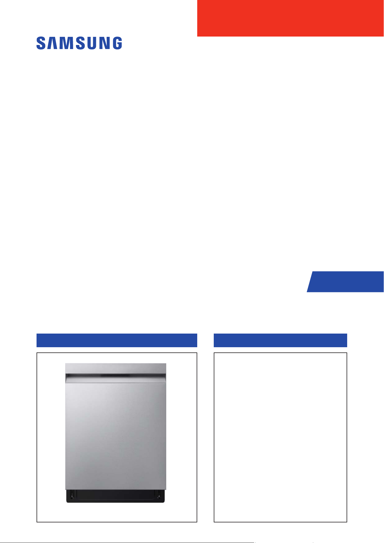
BASIC MODEL : DW70H73YCFR
MODEL NAME : DW70H7****** SERIES
MODEL CODE : DW70H7****
1. Safety Instructions
2. Features and Specications
3. Disassembly and Reassembly
4. Troubleshooting
5. PCB Diagram
6. Wiring Diagram
7. Reference

SAMSUNG PROPRIETARY. DO NOT COPY OR DISTRIBUTE WITHOUT PERMISSION
SAMSUNG PROPRIETARY. DO NOT COPY OR DISTRIBUTE WITHOUT PERMISSION
Disclaimer:
This manual contains condential and proprietary information of Samsung
Electronics Co., Ltd. ("Samsung")
All text, graphics, user interfaces, visual interfaces, photographs,
trademarks, and logos (collectively, "Content"), including but not
limited to the design, structure, selection, coordination, "look and feel"
and arrangement of such Content, contained in this manual is owned,
controlled or licensed by or to Samsung, and is protected by trade dress,
copyright, patent and trademark laws, and various other intellectual
property rights and unfair competition laws.
No part of this manual or the Content may be copied, reproduced,
republished, uploaded, posted, publicly displayed, encoded, translated,
transmitted or distributed in any way (including "mirroring") to anyone, any
entity, any other computer, server, Web site or other medium for publication
or distribution or for any commercial purpose, without Samsung’s express
prior written consent.
Samsung reserves the right, at its sole discretion, to change, modify,
add or remove portions of any part of this manual at any time. It is your
responsibility to check the manual periodically for changes. Your use of the
manual will mean that you accept and agree to this disclaimer. If you do
not agree with any part of this disclaimer, please stop using this manual
immediately.
This Document can not be used without Samsung’s authorization.

SAMSUNG PROPRIETARY. DO NOT COPY OR DISTRIBUTE WITHOUT PERMISSION
SAMSUNG PROPRIETARY. DO NOT COPY OR DISTRIBUTE WITHOUT PERMISSION
This Document can not be used without Samsung’s authorization.
CONTENTS
1. SAFETY INSTRUCTIONS ............................................................................... 1
1-1. SAFETY INSTRUCTIONS FOR SERVICE ENGINEERS ................................. .....................1
2. FEATURES AND SPECIFICATIONS ....................................................................5
2-1. FEATURES ............................................................................................5
2-2. KEY BENEFITS SUMMARY .............................................................................6
2-3. SPECIFICATIONS ......................................................................................6
2-4. PRODUCT OVERVIEW. . . . . . . . . . . . . . . . . . . . . . . . . . . . . . . . . . . . . . . . . . . . . . . . . . . . . . . . . . . . . . . . . . . . . . . . . . . . . . . . . . 9
2-5. OPTIONS SPECIFICATIONS .................... .................. ................. .................. ...10
2-6. CONTROL PANEL .....................................................................................11
2-6-1. CONTROL PANEL ........................................................................................ 11
2-7. CONTROL PANEL .....................................................................................12
2-7-1. INDICATOR ..............................................................................................12
2-8. CYCLE OVERVIEW ....................................................................................13
2-9. CYCLE CHART ........................................................................................14
2-10. SMARTTHINGS (APPLICABLE MODELS ONLY) .........................................................15
2-10-1. SMARTTHINGS (APPLICABLE MODELS ONLY) ...........................................................15
2-10-2. SMARTTHINGS FUNCTIONS
............................................................................17
3. DISASSEMBLY AND REASSEMBLY ...................................................................18
3-1. TOOLS FOR REMOVAL AND REASSEMBLY .............................................................18
3-2. STANDARD DISASSEMBLY DRAWINGS ................................................................19
3-2-1. PRECAUTION ............................................................................................19
3-2-2. DISTRIBUTION MOTOR
...................................................................................20
3-2-3. CIRCULATION PUMP / HEATER
...........................................................................23
3-2-4. DRAIN PUMP
............................................................................................28
3-2-5. CASE BRAKE / CAP CASE BRAKE / GASKET BRAKE
........................................................30
3-2-6. DRAIN HOSE
............................................................................................34
3-2-7. AQUA STOP
..............................................................................................38
3-2-8. WATER SOFTENER / FRAME FRONT. . . . . . . . . . . . . . . . . . . . . . . . . . . . . . . . . . . . . . . . . . . . . . . . . . . . . . . . . . . . . . . . . . . . . . . 41
3-2-9. ASSY SUMP / SEAL SUMP
................................................................................46
3-2-10. HOSE SUMP IN
.........................................................................................51
3-2-11. DOOR SWITCH
..........................................................................................53
3-2-12. ASSY-PANEL CONTROL / WI-FI PBA (DW70****F*/DW70****S*/DW70****U*)
...........................54
3-2-13. ASSY-PANEL CONTROL / WI-FI PBA (DW70****B*/ DW70****I*)
........................................57
3-2-14. AUTO DOOR PBA
.......................................................................................61
3-2-15. DOOR LOCK HOOK
......................................................................................62
3-2-16. DOOR OUTER
...........................................................................................63
3-2-17. DOOR INNER / DOOR HINGE (EXCEPT DW70*****I*)
.....................................................64
3-2-18. DOOR INNER / DOOR HINGE (EXCEPT DW70*****I*)
.....................................................67
3-2-19. DAMPER DOOR
.........................................................................................71
3-2-20. HOLDER HINGE
........................................................................................72
3-2-21. HOLDER ROPE DOOR / SPRING DOOR
...................................................................73
3-2-22. MAIN PBA
..............................................................................................75
3-2-23. PRESSURE SWITCH
.....................................................................................77
3-2-24. THERMISTOR
...........................................................................................78
3-2-25. TURBIDITY SENSOR
....................................................................................79
3-2-26. DETERGENT DISPENSER
................................................................................80
3-2-27. SEAL TUB PACKING
.....................................................................................83

SAMSUNG PROPRIETARY. DO NOT COPY OR DISTRIBUTE WITHOUT PERMISSION
SAMSUNG PROPRIETARY. DO NOT COPY OR DISTRIBUTE WITHOUT PERMISSION
This Document can not be used without Samsung’s authorization.
CONTENTS
3-2-28. ROTOR LOWER / ASSY DUCT NOZZLE ....................................................................85
3-2-29. ASSY ROTOR MIDDLE
...................................................................................88
3-2-30. COARSE FILTER / FINE FILTER / MICRO FILTER
...........................................................89
3-2-31. BASKET MIDDLE
........................................................................................90
3-2-32. BASKET LOWER
........................................................................................92
3-2-33. BASKET 3RD. . . . . . . . . . . . . . . . . . . . . . . . . . . . . . . . . . . . . . . . . . . . . . . . . . . . . . . . . . . . . . . . . . . . . . . . . . . . . . . . . . . . . . . . . . . . 93
3-2-34. RAIL BASKET / HOLDER RAIL REAR
................................ ......................................94
3-2-35. COVER PLINTH
.........................................................................................95
3-2-36. COVER TOP
.............................................................................................97
3-2-37. SIDE PANEL / GUIDE TUB TOP / COVER TUB REAR (DW70****F*)
......................................... 98
3-2-38. SIDE PANEL / GUIDE TUB TOP / COVER TUB REAR (EXCEPT DW70****F*)
...............................102
3-2-39. BASKET CUTLERY
......................................................................................104
3-3. CHECKPOINTS AFTER FINISHING A SERVICE ........................................................ 105
4. TROUBLESHOOTING ...............................................................................106
4-1. INFORMATION CODES ............................................ ........................ .......... 106
4-2. SVC TEST MODE .....................................................................................107
4-3. INFORMATION HOW TO ACCESS DATA RECORDS .................................................... 109
4-4. MALFUNCTION TABLE. . . . . . . . . . . . . . . . . . . . . . . . . . . . . . . . . . . . . . . . . . . . . . . . . . . . . . . . . . . . . . . . . . . . . . . . . . . . . . .110
4-5. CHECK CODE TROUBLE SHOOTING ..................................................................118
4-6. CYCLE CHART .......................................................................................122
5. PCB DIAGRAM .....................................................................................123
5-1. FUNCTION OF CONNECTORS & RELAYS (MAIN PCB ) ..................................................123
5-2. DETAILED DESCRIPTION OF CONNECTORS & TERMINALS (MAIN PBA ) ................................124
5-3. FUNCTION OF CONNECTORS & TERMINALS (SUB PCB) ....................... ............. ............125
5-4. DETAILED DESCRIPTION OF CONNECTORS & TERMINALS (SUB PBA) ..................................126
6. WIRING DIAGRAM .................................................................................127
6-1. WIRING DIAGRAM ..................................................................................127
7. REFERENCE .......................................................................................128
7-1. MODEL NUMBER NAMING RULES .................................................................. 128
7-2. TERMINOLOGY ...................................... ...... ...... ....... ...... ...... ....... ...... ....129
7-3. SMARTTHINGS (APPLICABLE MODELS ONLY) ....................................................... 130
7-3-1. SMARTTHINGS (APPLICABLE MODELS ONLY). . . . . . . . . . . . . . . . . . . . . . . . . . . . . . . . . . . . . . . . . . . . . . . . . . . . . . . . . . . . 130
7-3-2. SMARTTHINGS FUNCTIONS
............................................................................132
Safety Instructions _ 1
SAMSUNG PROPRIETARY. DO NOT COPY OR DISTRIBUTE WITHOUT PERMISSION
SAMSUNG PROPRIETARY. DO NOT COPY OR DISTRIBUTE WITHOUT PERMISSION
This Document can not be used without Samsung’s authorization.
1. SAFETY INSTRUCTIONS
1-1. SAFETY INSTRUCTIONS FOR SERVICE ENGINEERS
ሪ Make sure to observe the following instructions to operate the product correctly and safely and prevent possible accidents
and hazards while servicing.
ሪ Two types of safety symbols, Warning and Caution, are used in safety instructions.
Warning
Hazards or unsafe practices that may result in severe personal injury or death.
Caution
Hazards or unsafe practices that may result in minor personal injury or property damage.
Warning
Before Servicing
ࣃ When servicing electrical parts or harnesses. Make sure to disconnect the circuit BREAKER or power cable before servicing.
ࣃ An Electrical safety test must be performed before and after any repair. Refer to Samsung Electric Safety test Policy.
Failing to do so may result in a risk of electric shock.
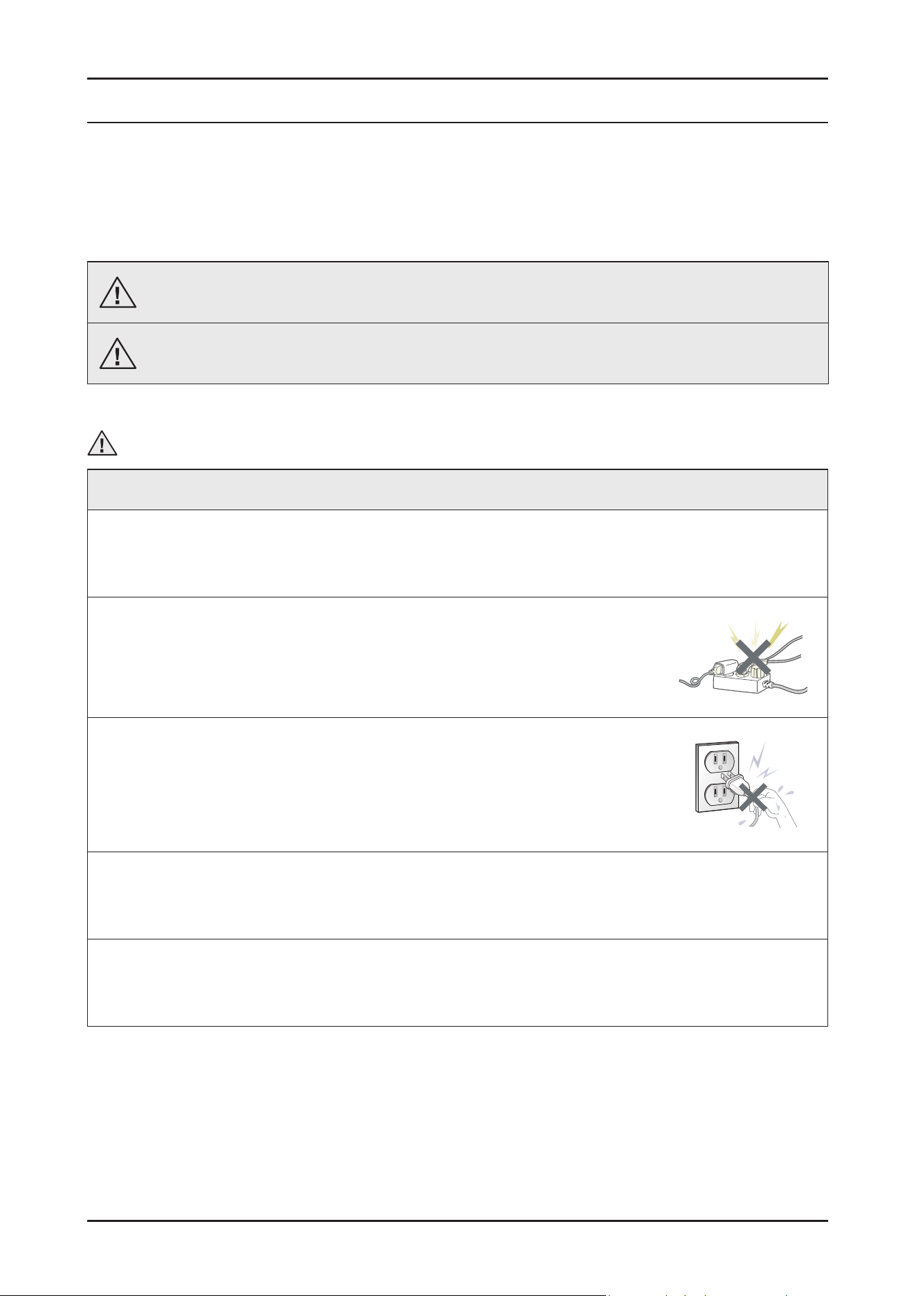
ࣃ Do not allow consumers to connect several appliances to a single power outlet at the same time.
There is a risk of re due to overheating.
ࣃ When removing the power cord, make sure to hold the power plug when pulling the plug from the outlet.
Failing to do so may damage the plug and result in re or electric shock.
ࣃ When the dishwasher is not being used, make sure to disconnect the circuit breaker or power cable from the power outlet.
Failing to do so may result in electric shock or re due to lightning.
ࣃ Do not place or use gasoline, thinners, alcohol, or other ammable or explosive substances near the dishwasher.
There is a risk of explosion and re caused from electric sparks.
2 _ Safety Instructions
SAMSUNG PROPRIETARY. DO NOT COPY OR DISTRIBUTE WITHOUT PERMISSION
SAMSUNG PROPRIETARY. DO NOT COPY OR DISTRIBUTE WITHOUT PERMISSION
This Document can not be used without Samsung’s authorization.
Warning
While Servicing
ࣃ Check if the power cable is damaged, attened, cut or otherwise degraded.
ࣃ If faulty, replace it immediately.
Failing to do so may result in electric shock or re.
ࣃ Completely remove any dust or foreign material from the housing, wiring and connection parts.
This will prevent a risk of re due to tracking and shorts in advance.
ࣃ When connecting wires, make sure to connect them using the relevant connectors and check that they are completely connected.
If tape is used instead of the connectors, it may cause re due to tracking.
ࣃ Make sure to discharge the PBA power and capacitor terminals before starting the service.
Failing to do so may result in a high voltage electric shock.
ࣃ When replacing the heater, make sure to fasten the holder heater after ensuring that it is inserted into the bracket- heater.
Ensure the heater is tted into the bracket - heater correctly.
ࣃ Ensure that the heater is inserted into the heater bracket rst and then tighten the heater holder.
ࣃ Do not repair the dishwasher without safety gloves.
It may cause injury.
ࣃ Due to the heavyweight it is recommend for 2 or more people to handle the product.
Warning
After Servicing
ࣃ Check for any water leakage.
Perform a test run on the dishwasher using the standard(Eco) cycle and check whether there is any water leakage on the oor
section or the pipes.
ࣃ Do not allow consumers to repair or service any part of the dishwasher themselves.
This may result in personal injury and shorten the product lifetime.
Safety Instructions _ 3
SAMSUNG PROPRIETARY. DO NOT COPY OR DISTRIBUTE WITHOUT PERMISSION
SAMSUNG PROPRIETARY. DO NOT COPY OR DISTRIBUTE WITHOUT PERMISSION
This Document can not be used without Samsung’s authorization.
Caution
Before Servicing
ࣃ Do not sprinkle water onto the dishwasher directly when cleaning it.
This may result in electric shock or re, and may shorten the product lifetime.
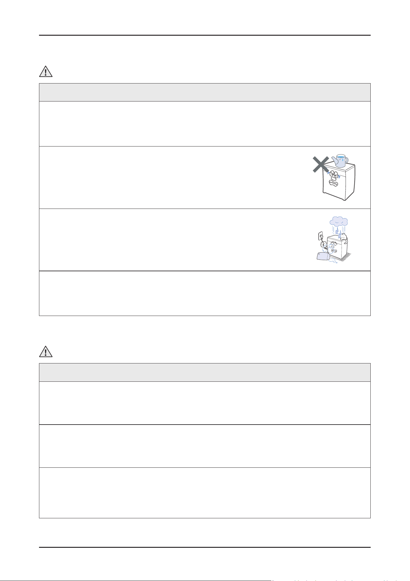
ࣃ Do not place any containers with water on the dishwasher.
If the water is spilled, it may result in electric shock or re. This will also shorten the product lifetime.
ࣃ Do not install the dishwasher in a location exposed to snow or rain.
This may result in electric shock or re, and shorten the product lifetime.
ࣃ Do not press a control button using a sharp tool or object.
This may result in electric shock or damage to the product.
Caution
During Servicing
ࣃ When wiring a harness, make sure to seal it completely so no liquid can enter.
Make sure that they do not break when force is exerted.
ࣃ Check if there is any residue that shows that liquid entered the electric parts or harnesses.
If any liquid has entered into a part, replace it or completely remove any remaining moisture from it.
ࣃ If you need to place the dishwasher on its back for servicing purposes, place a support(s) on the oor and lay it down carefully so the
back is on the oor.
Do not lay it down on its front or side. This may result in scratches to the surface or damage to the parts.
4 _ Safety Instructions
SAMSUNG PROPRIETARY. DO NOT COPY OR DISTRIBUTE WITHOUT PERMISSION
SAMSUNG PROPRIETARY. DO NOT COPY OR DISTRIBUTE WITHOUT PERMISSION
This Document can not be used without Samsung’s authorization.
Caution
After Servicing
ࣃ Check the assembled status of the parts.
They must be the same as before servicing.
ࣃ Check the insulation resistance.
Disconnect the circuit breaker or power cable from the power outlet and measure the insulation resistance between the power
wires and the grounding wire of the dishwasher. The value must be greater than 10MΩ when measured with a 500V DC Megger.
ࣃ Check whether the product is level with the oor. Check if there are any deformations in the sink.
Check that the dishwasher is rmly installed to the sink.
Vibrations can shorten the lifetime of the product.
Caution
Electrical Safety Test
ࣃ Before servicing any home appliance, it’s the best to perform a complete electrical safety checks to conrm the product is safe to
handle. Tests like earth-continuity, insulation-resistance (using a megger where appropriate), and basic voltage or polarity checks with
a standard meter verify that the appliance has no hidden electrical faults that could pose a risk during repair.
These checks ensure proper grounding, conrm there is no breakdown in insulation, and validate that the electrical path is stable and
secure. Performing these tests rst protects both the engineer and the customer, ensuring the appliance is electrically healthy before
any service work begins.
ࣃ Performing the Outlet test (where you are allowed to) helps with dening any potential issues in the environment and helps you with
better diagnosis and reduces the chance of redo due to external factors.
ࣃ Make sure your test devices are following the required standards, have fully charged battery, are calibrated and always use
manufacturer-approved accessories such as test leads, probs and clips.
ࣃ Having a “DO NOT USE” sticker can help you and customers to dene a faulty appliance and keeps everyone safe.
Features and Specications _ 5
SAMSUNG PROPRIETARY. DO NOT COPY OR DISTRIBUTE WITHOUT PERMISSION
SAMSUNG PROPRIETARY. DO NOT COPY OR DISTRIBUTE WITHOUT PERMISSION
This Document can not be used without Samsung’s authorization.
2. FEATURES AND SPECIFICATIONS
2-1. Features
• Energy Grade : C (DW70******)
• Installation type : Free-Standing (FS), Built Under (BU), Fully Built In (FBI) Type
- FS : DW70****F*
- BU : DW70****U*
- FBI : DW70****B*, DW70****I* (Slide Hinge models)
Note: ‘ * ’ Asterisk(s) means variant model and can be varied (0-9) or (A-Z).
6 _ Features and Specications
SAMSUNG PROPRIETARY. DO NOT COPY OR DISTRIBUTE WITHOUT PERMISSION
SAMSUNG PROPRIETARY. DO NOT COPY OR DISTRIBUTE WITHOUT PERMISSION
This Document can not be used without Samsung’s authorization.
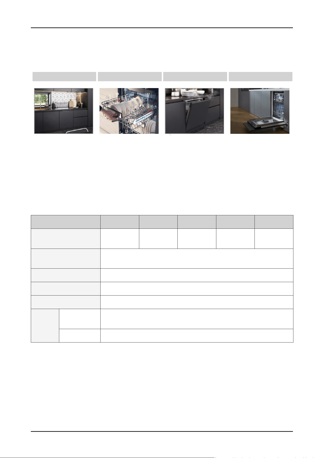
2-2. Key Benets Summary
2-3. Specications
Model Name DW70****F* DW70****S* DW70****U* DW70****B* DW70****I*
Type Free Standing Semi Built-in Built Under Fully Built In
Fully Built In
(Sliding)
Power
220 – 240 V~, 50 Hz
(DW70H73YMFR: 60Hz)
Water Pressure 0.04 – 1.0 MPa
Rated Power 1760 – 2100 W
Wash Type
Rotating Nozzle Spray
Wash
Capacity
DW70H73***
(DW70H75***)
14 Place settings
DW70H72*** 13 Place settings
C Energy Efciency Flex Load Basket Auto Open Dry Kitchen Fit™
C Energy Grade - Ball Bearing Rail
- Flexible basket design
- Convertible Meal 3rd Rack
- Adjustable height
- Auto open to dry
- Express wash & dry
- Seamless sliding door
- Up to 10kg Panel
( DW70****I* models only )
Features and Specications _ 7
SAMSUNG PROPRIETARY. DO NOT COPY OR DISTRIBUTE WITHOUT PERMISSION
SAMSUNG PROPRIETARY. DO NOT COPY OR DISTRIBUTE WITHOUT PERMISSION
This Document can not be used without Samsung’s authorization.
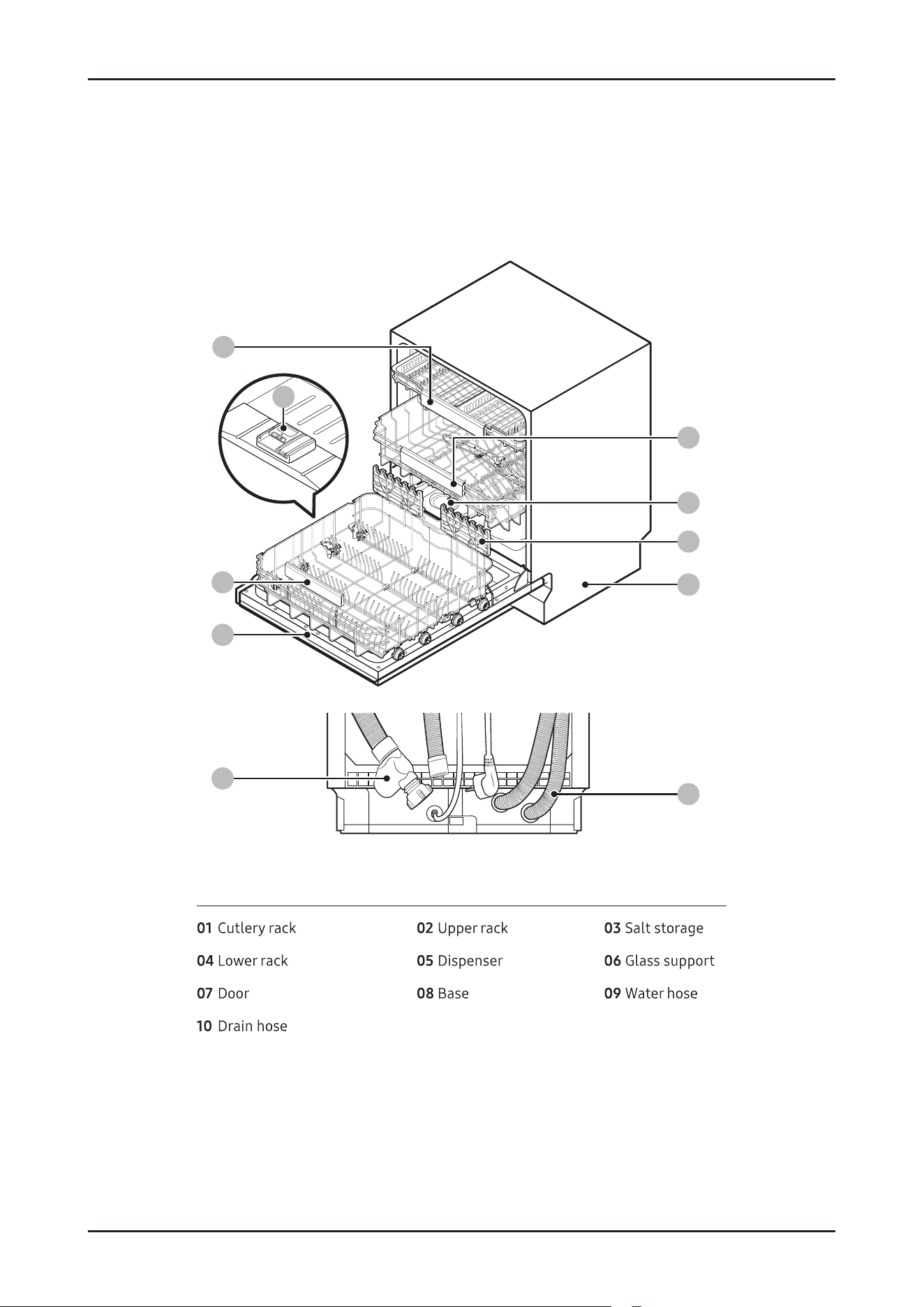
■ DW70H73**** models
09
08
04
07
05
01
02
03
06
10
09
8 _ Features and Specications
SAMSUNG PROPRIETARY. DO NOT COPY OR DISTRIBUTE WITHOUT PERMISSION
SAMSUNG PROPRIETARY. DO NOT COPY OR DISTRIBUTE WITHOUT PERMISSION
This Document can not be used without Samsung’s authorization.
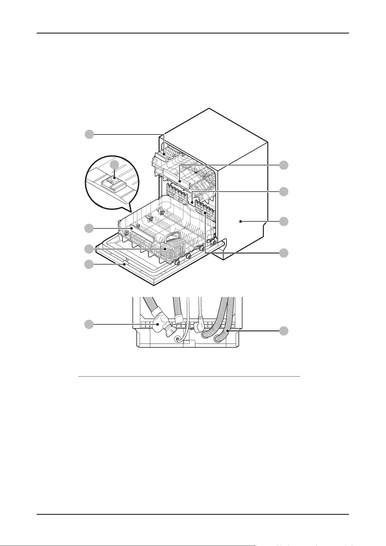
■ DW70H72**** models
09
08
04
07
06
05
01
02
03
11
09
10
01 kcar efinK 02 kcar reppU 03 egarots tlaS
04 kcar rewoL 05 resnepsiD 06 teksab yreltuC
07 rooD 08 esaB 09 Water hose
10 Drain hose 11 troppus ssalG
Features and Specications _ 9
SAMSUNG PROPRIETARY. DO NOT COPY OR DISTRIBUTE WITHOUT PERMISSION
SAMSUNG PROPRIETARY. DO NOT COPY OR DISTRIBUTE WITHOUT PERMISSION
This Document can not be used without Samsung’s authorization.
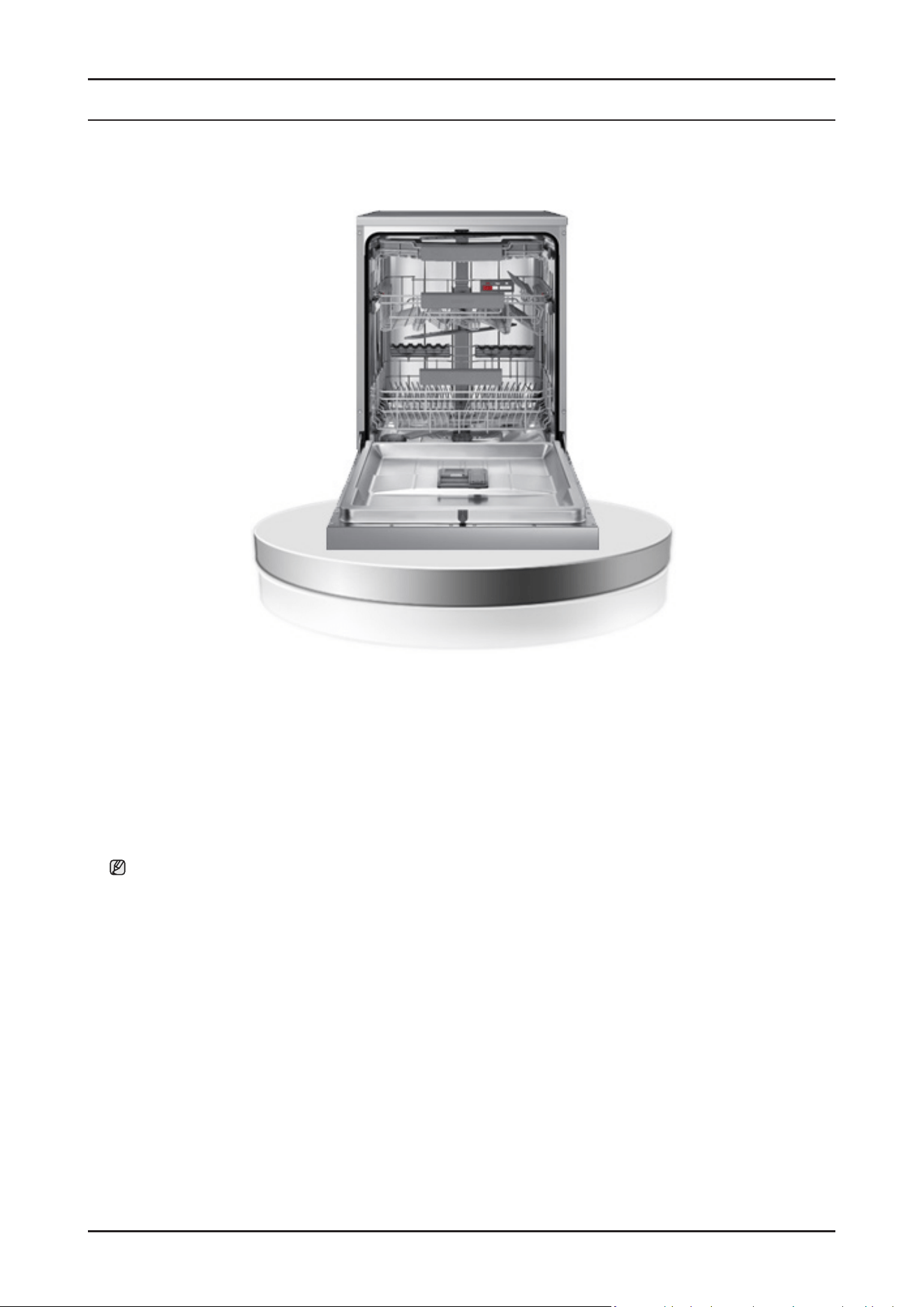
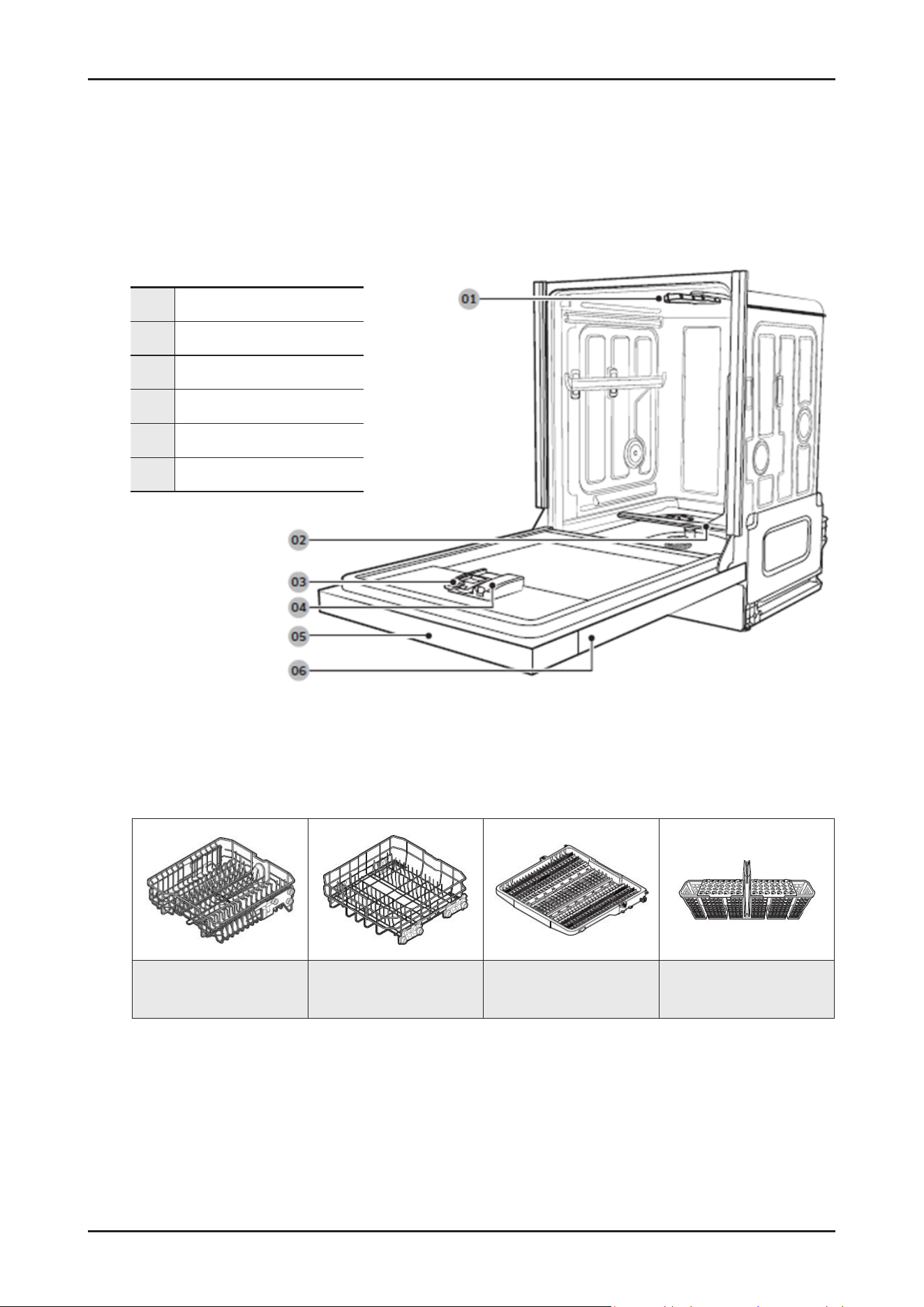
■ Dishwasher at a glance
■ Accessories
2-4. Product overview
01 Top spray arm
02 Bottom spray arm
03 Detergent compartment
04 Rinse aid compartment
05 Control panel
06 Door
Upper rack Lower rack
3rd rack
(Applicable models only)
Cutlery basket
10 _ Features and Specications
SAMSUNG PROPRIETARY. DO NOT COPY OR DISTRIBUTE WITHOUT PERMISSION
SAMSUNG PROPRIETARY. DO NOT COPY OR DISTRIBUTE WITHOUT PERMISSION
This Document can not be used without Samsung’s authorization.
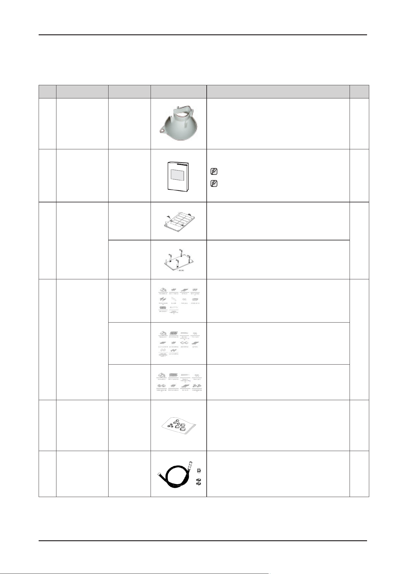
2-5. Options specications
No. Unit Part Code Figure Description Q’ty
1
GUIDE SALT
DD81-02921A
For easy lling of the salt storage
1
2
USER MANUAL
TBD
To explain the product operation and installation
Note : “*” Asterisk(s) can be varied (A-Z)
Note : You can nd the User Manual on the web site
(www.samsung.com/support/)
1
3
INSTALL MANUAL
DD81-03007A
To install the decorative panel
- For Fully Built In models (DW70****B*)
1
DD81-02969A
To install the decorative panel
- For Fully Built In Sliding models (DW70****I*)
4
Installation kit
DD81-02985A
Installation Kit for Built Under models
- DW70****U*
1
DD81-02985B
Installation Kit for Fully Built In models
- DW70****B*
DD82-01578B
Installation Kit for Fully Built In Sliding models
- DW70****I*
5
Clamper Kit
DD81-02922A
- Φ 17.5 (DD81-01145A) x 1 pc
-
Φ 28.6 (DD81-01409A) x 3 pcs
-
Φ 39.6 (DD81-02482A) x 2 pcs
-
Φ 46.0 (DD81-02481A) x 2 pcs
1
6
Extension Drain
Hose Kit
DD82-01712B
To extend the length of drain hose
(Length of Drain hose : 1.8m)
1
Features and Specications _ 11
SAMSUNG PROPRIETARY. DO NOT COPY OR DISTRIBUTE WITHOUT PERMISSION
SAMSUNG PROPRIETARY. DO NOT COPY OR DISTRIBUTE WITHOUT PERMISSION
This Document can not be used without Samsung’s authorization.
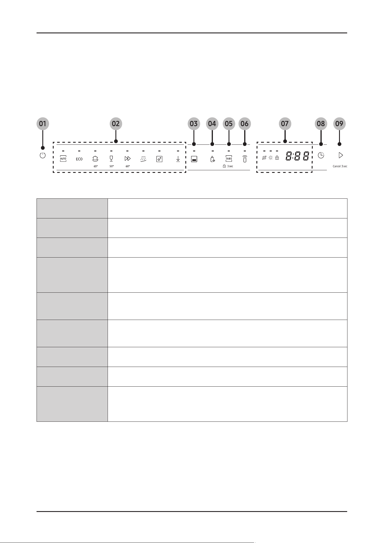
2-6. Control Panel
2-6-1. Control Panel
1. Power Press to turn the dishwasher on or off.
2.
Cycle Press to select a desired wash cycle. For more information, see the “Cycle overview” section
3.
Lower rack only Press to wash items using only the lower rack.
4.
Sanitize
Press to increase the water temperature up to 69 °C in the nal rinse process for high
temperature sanitization.
This option is not available with Auto, Quick, Self Clean and Delicate.
5.
Multi tab
Press to select the Multi tab option which allows the replacement of salt and rinse aid with a
Multi detergent tablets.
6.
Smart Control
You can check product operation remotely by using Smart Control. For more details, see the
separate manual included with the product.
7.
Display You can check various information on the display
8.
Delay Start You can delay the cycle starting time up to 24 hours.
9.
START (Cancel 3 sec)
Press START to start operation. Make sure the door is closed.
- Cancel 3 sec: Tap and hold this button for 3 seconds to cancel the current cycle and drain
the dishwasher.
12 _ Features and Specications
SAMSUNG PROPRIETARY. DO NOT COPY OR DISTRIBUTE WITHOUT PERMISSION
SAMSUNG PROPRIETARY. DO NOT COPY OR DISTRIBUTE WITHOUT PERMISSION
This Document can not be used without Samsung’s authorization.
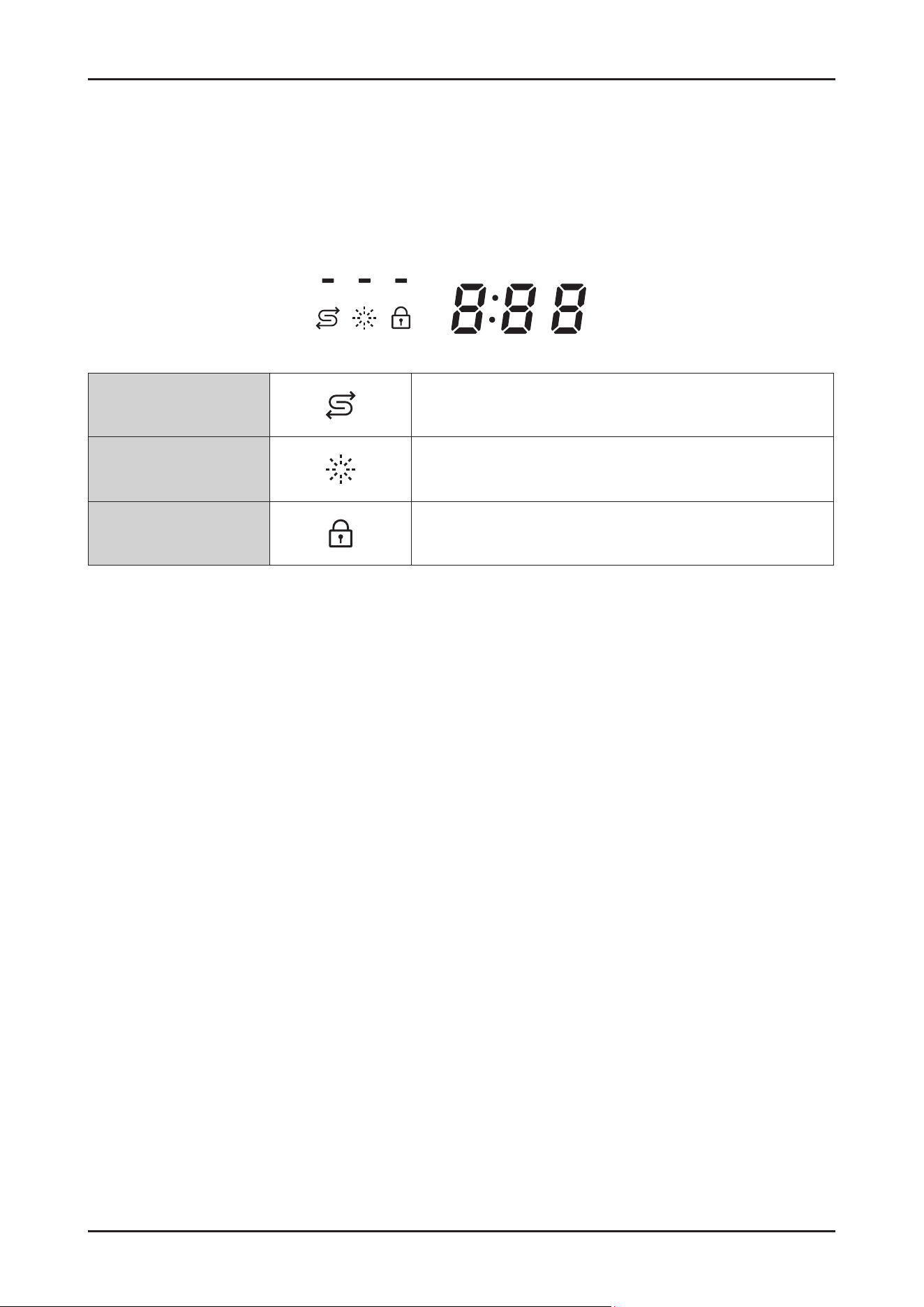
2-7. Control Panel
2-7-1. Indicator
2-3-2. Delay Start
You can delay the cycle starting time up to 24 hours in 1-hour increments.
To increase the delay time, press Delay Start. The hour displayed indicates the time at which the cycle will start.
1.
Open the door, and then load the dishwasher.
2.
Press Delay Start to change the time in 1-hour increments.
- If you press and hold the button, the time will increase until you release the button.
3.
Press Start, and then close the door.
2-3-3. Control Lock
To prevent children from playing with the dishwasher, Control Lock locks all the control buttons except for POWER.
•
To activate Control Lock, press and hold Control Lock for 3 seconds.
With Control Lock activated, you cannot select a cycle or option, or start an operation.
•
To deactivate Control Lock, press and hold Control Lock again for 3 seconds.
No Salt indicator Lights up when the salt storage runs out of salt.
Rinse Rel indicator Lights up when the dishwasher runs out of rinse aid.
Control Lock indicator
Lights up if Control Lock is activated.
Features and Specications _ 13
SAMSUNG PROPRIETARY. DO NOT COPY OR DISTRIBUTE WITHOUT PERMISSION
SAMSUNG PROPRIETARY. DO NOT COPY OR DISTRIBUTE WITHOUT PERMISSION
This Document can not be used without Samsung’s authorization.
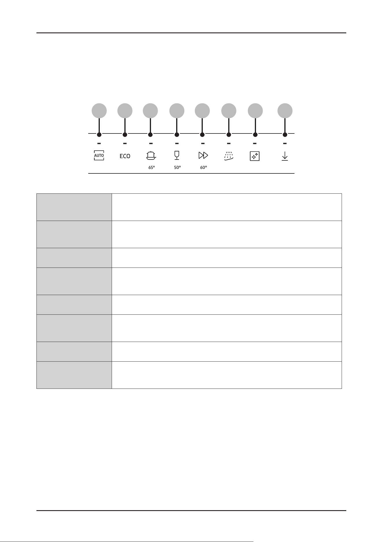
2-8. Cycle overview
1.
AUTO
This cycle detects the level of soil and automatically initiates the optimal cycle,
which is appropriate for all levels of soiled items.
2.
ECO
This cycle reduces power and water consumption, which is appropriate for normally soiled
items.
3.
Intensive Select this cycle for heavily soiled items.
4.
Delicate
Select this cycle for lightly soiled, fragile items such as glasses. Sanitize option is not
available in this cycle.
5.
Express Normally soiled daily using items, with short cycle time.
6.
Pre Wash
This cycle is for pre-washing the items with cold water to remove dirt before running
another wash cycle.
7.
Machine Care This cycle is for cleaning the inside of the dishwasher.
8.
Downloaded
You can download a cycle from the SmartThings app and use this button to select the
downloaded cycle
01 02 03 04 05 06 07 08
14 _ Features and Specications
SAMSUNG PROPRIETARY. DO NOT COPY OR DISTRIBUTE WITHOUT PERMISSION
SAMSUNG PROPRIETARY. DO NOT COPY OR DISTRIBUTE WITHOUT PERMISSION
This Document can not be used without Samsung’s authorization.
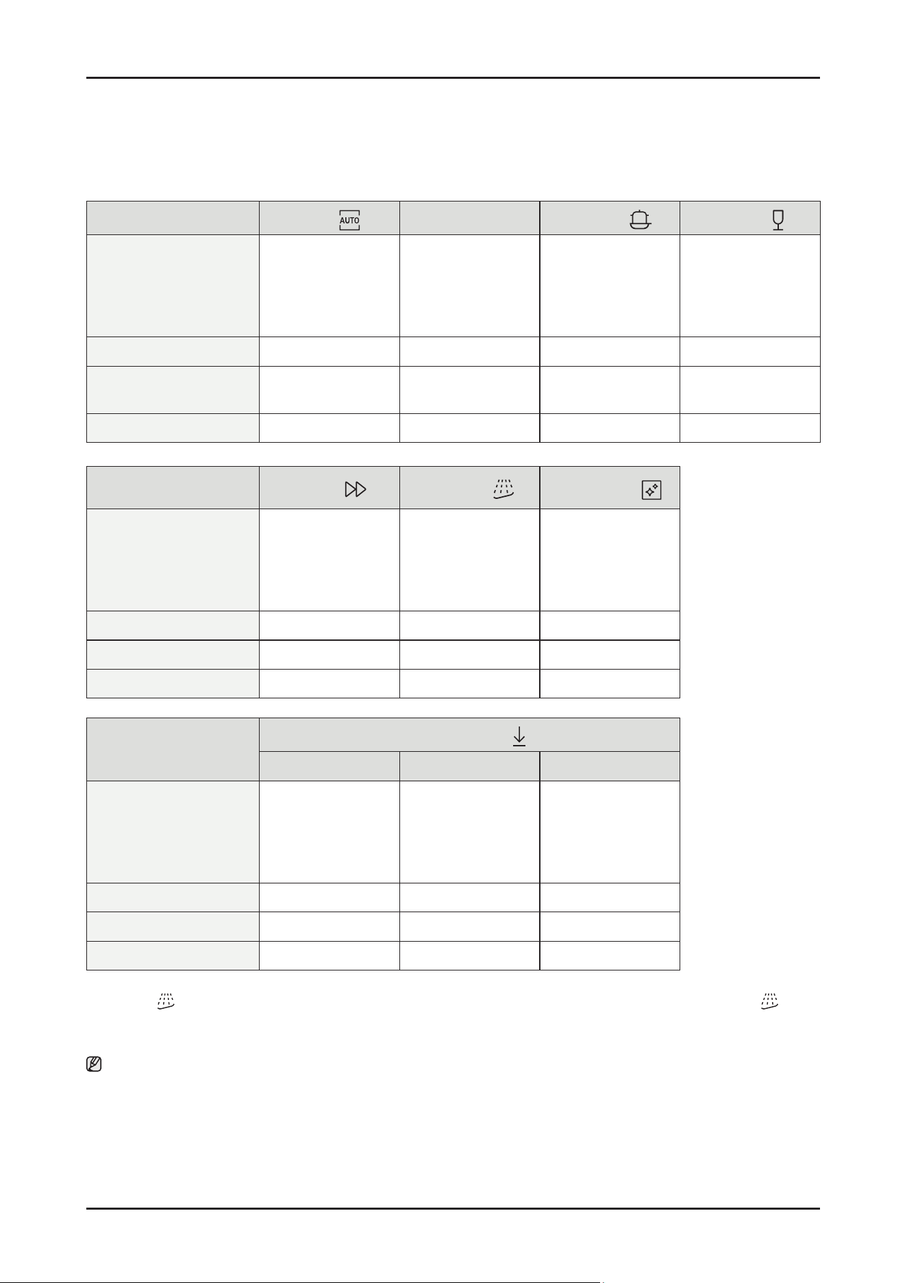
2-9. Cycle Chart
Cycle
AUTO
ECO
Intensive
Delicate
Cycle sequence
Pre wash (45 °C) >
Main wash (55-65 °C) >
Rinse >
Hot Rinse (50- 58 °C) >
Dry > End
Main wash (48 ° C) >
Rinse >
Hot Rinse (45 °C) >
Dry > End
Pre wash (50 °C) >
Main wash (65 °C) >
Rinse >
Hot Rinse (63 °C) >
Dry > End
Pre wash (40 °C) >
Main wash (50 °C) >
Rinse (50 °C) >
Hot Rinse (50 °C) >
Dry > End
Water consumption (L) 7.8-1 7. 3 10.5 17.3 13.9
Energy consumption (kWh) 0.650-1.500
0.746 (14 P/S)
0.735 (13 P/S)
1.535 0.950
Cycle time (min.) 129-150 220 205 120
Cycle
Express
Pre Wash *
Machine Care
Cycle sequence
Main wash (60 °C) >
Rinse (50 °C) >
Hot Rinse (63 °C) >
Dry > End
Pre wash > End Pre wash >
Main wash (70 °C) >
Rinse >
Hot Rinse (70 °C) >
Dry > End
Water consumption (L) 12.1 4.1 14.9
Energy consumption (kWh) 1.050 0.02 1.510
Cycle time (min.) 60 15 145
Cycle
Download cycle
Plastic Pots & Pans Baby Care
Cycle sequence
Pre wash >
Main wash (60 °C) >
Rinse >
Hot Rinse (60 °C) >
Dry > End
Pre wash (50 °C) >
Main wash (68 °C) >
Rinse >
Hot Rinse (70 °C) >
Dry > End
Pre wash >
Rinse >
Hot Rinse (70 °C) >
Dry > End
Water consumption (L) 14.1 21.5 10.6
Energy consumption (kWh) 1.080 1.610 0.755
Cycle time (min.) 129 172 79
* Pre Wash : This cycle does not activate the AutoRelease™ function nor the drying process. Continuous use of the Pre Wash cycle
for an extended time is not recommended. This may reduce the performance of the water softener.
Note
• The cycle time depends on the options you have added, and the pressure and temperature of the supplied water.
•
The power consumption depends on the water temperature and/or load.
• Energy values for courses were calculated under standardized testing conditions.

Features and Specications _ 15
SAMSUNG PROPRIETARY. DO NOT COPY OR DISTRIBUTE WITHOUT PERMISSION
SAMSUNG PROPRIETARY. DO NOT COPY OR DISTRIBUTE WITHOUT PERMISSION
This Document can not be used without Samsung’s authorization.
2-10. SmartThings (Applicable models only)
2-10-1. SmartThings (Applicable models only)
■ Wi connection
On your smartphone, go to Settings and connect to your home Wi-Fi network.
■ Download
On an app market (Google Play Store, Apple App Store, Samsung Galaxy Apps), nd the SmartThings app with a search
term of “SmartThings”. Download and install the app on your device.
■ Log in
You must rst log into SmartThings with your Samsung account. To create a new Samsung account, follow the
instructions on the app. You don’t need a separate app to create your account.
Note
If you have a Samsung account, use the account to log in. A registered Samsung smartphone user automatically logs in.
■ Wi-Fi Off
To manually turn the Wi off, press and hold ‘Speed boosting button’ and ‘Smart control button’ for 3 seconds at same
time.
■ To register your device to SmartThings
1. Make sure your smartphone is connected to a wireless network.
2. Select to run SmartThings on your smartphone.
3. When a message of “A new device is found.”, select Add.
4. If no message appears, select + and select your dishwasher in a list of devices available.
If your dishwasher is not listed, select Device Type > Specic Device Model, and then add your dishwasher manually.
5. Follow the onscreen instructions to complete the connection process for your dishwasher.
6. When the process is complete, your dishwasher will appear in the list of devices on your SmartThings App.
7. iPhone user have to scan QR code or enter Serial Number(Code below the QR code) for using SmartThings app.
■ Customer’s Privacy with SmartThings
SmartThings protects customer data by following strict privacy standards and giving users full control.
The system is built to keep personal information secure through strong encryption and clear permission settings, so
nothing is accessed without the user’s approval. Samsung limits data collection to what’s needed for the service to work
and does not sell personal data.
The result is a smart-home platform that’s safe, transparent, and designed to respect customer privacy at every step. '
NOTE
Dishwasher app
Integrated control:
You can monitor and control your dishwasher both at home and on the go.
Select the dishwasher icon on SmartThings . The dishwasher page appears.
Check the operation status or notications related to your dishwasher, and change options or settings if necessary.
16 _ Features and Specications
SAMSUNG PROPRIETARY. DO NOT COPY OR DISTRIBUTE WITHOUT PERMISSION
SAMSUNG PROPRIETARY. DO NOT COPY OR DISTRIBUTE WITHOUT PERMISSION
This Document can not be used without Samsung’s authorization.
NOTE
• This device is designed for household use only (Class B), and can be used in all residential areas.
• This device may cause wireless interference, and neither the manufacturer nor the installer of this device can provide
a safety measure of any kind. Recommended encryption methods are WPA/TKIP and WPA2/AES .
Newly developed Wi-Fi protocols or unapproved Wi-Fi protocols are not supported.
• The reception sensitivity of a wireless network may be affected by surrounding wireless environments.
• If your Internet provider has registered the MAC address of your PC or the modem module for permanent use, your Samsung
dishwasher fails to connect to the Internet. If this happens, contact your Internet provider.
• The Internet rewall may interrupt your Internet connection. If this happens, contact your Internet provider.
• If Internet failure continues after following the measurement of your Internet provider, contact a local Samsung retailer or
service centre.
• For installing wired and wireless routers, refer to the user manual of the router you use.
• Samsung dishwasher supports the Wi-Fi 2.4 GHz protocols.
• Samsung dishwasher supports the IEEE802.11 b/g/n (2.4 GHz), Soft-AP protocols. ( IEEE802.11n is recommended)
• An unapproved wired/wireless router may fail to connect to Samsung dishwasher.
• The SmartThings app is available on Android and iOS devices. The app is optimised for Samsung phones.
• Some functions of the app may operate differently on third-party devices.
• The app is subject to change without notice for improved performance.
• In addition, further updates on the app or the function in the app may stop caused by usability and security reasons, even if
updates are currently supported on your OS.
• Your device uses non-harmonised frequency and is intended for use in all European countries.
The WLAN can be operated in the EU without restriction indoors, but cannot be operated outdoors in France.
• You can easily install the SmartThings app or use the product with your phone by scanning the QR code on the attached label.
• Hereby, Samsung Electronics, declares that the radio equipment type appliance is in compliance with Directive 2014/53/
EU . The full text of the EU declaration of conformity is available at the following internet address: The ofcial Declaration of
conformity may be found at http://www.samsung.com , go to Support > Search Product Support and enter the model name.
• The overall standby power consumption is 2.0 W in which all network ports stay in “on” condition.
- Data determined according to standard E N 50564 and Regulation (EC) N o 1275/2008
Wi-Fi
Frequency range Transmitter power (Max)
2412 MHz - 2472 MHz 20 dBm
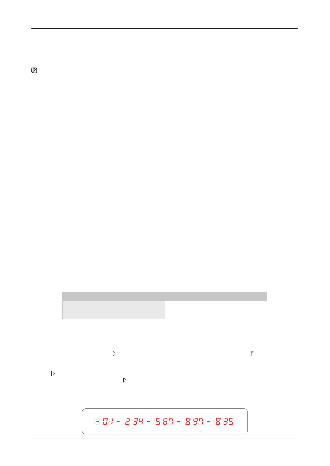
■ WSN
1. How to access: tap and hold Start in AP mode. (To enter the AP mode, tap and hold Smart Control for 3 seconds.)
2. Display format
- After receiving WSN data from WiFi module, “-” + rst 2 digits are diplayed and next 3 digits are diplayed by every Start
button tapping.
- Beep is generated when the Start button is tapped for displaying digits.
- Display example : “-” for the starting display
ex) WSN : “ 01234567897835”
Features and Specications _ 17
SAMSUNG PROPRIETARY. DO NOT COPY OR DISTRIBUTE WITHOUT PERMISSION
SAMSUNG PROPRIETARY. DO NOT COPY OR DISTRIBUTE WITHOUT PERMISSION
This Document can not be used without Samsung’s authorization.
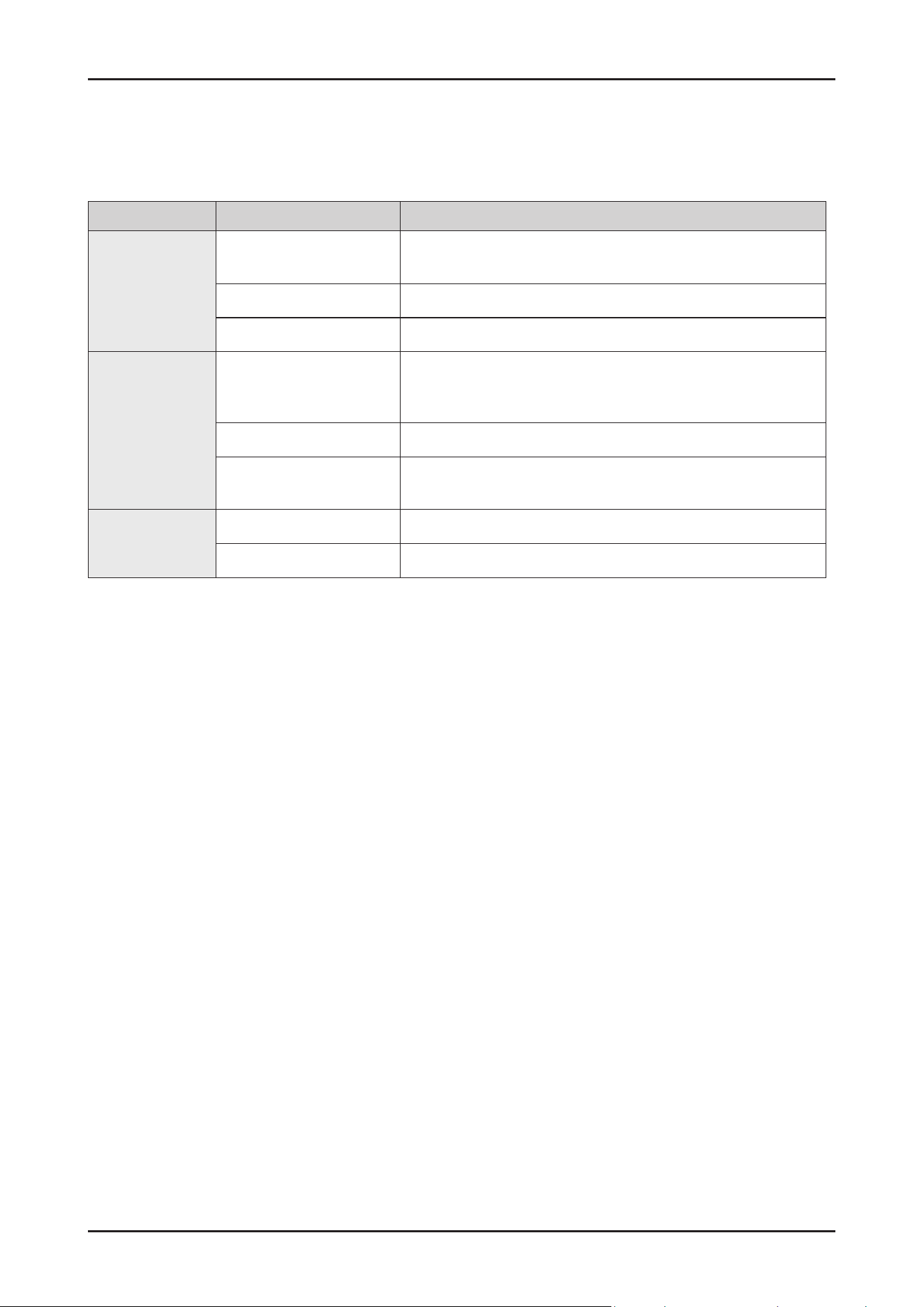
2-10-2. SmartThings functions
Category Function Description
Monitoring
Washing status
You can check the current cycle and its options, and the remaining
cycle time.
Smart Control The Smart Control status is shown for the dishwasher.
Energy monitoring Use this to monitor the energy consumption status.
Control
Start/ Pause/ Cancel
Select a cycle and necessary options, and then select Start/ Pause/
Cancel to start an operation, to stop temporarily, or to cancel the
current operation.
My Favorite Add frequently used cycles and options to My Favorite for later use.
Delay Start
Set Delay Start to start the cycle at a scheduled time
(up to 24 hours).
Notication
Cycle completed Noties you when the current cycle is complete.
Detergent Noties you if the dishwasher is out of rinse aid.
18 _ Disassembly and Reassembly
SAMSUNG PROPRIETARY. DO NOT COPY OR DISTRIBUTE WITHOUT PERMISSION
SAMSUNG PROPRIETARY. DO NOT COPY OR DISTRIBUTE WITHOUT PERMISSION
3. DISASSEMBLY AND REASSEMBLY
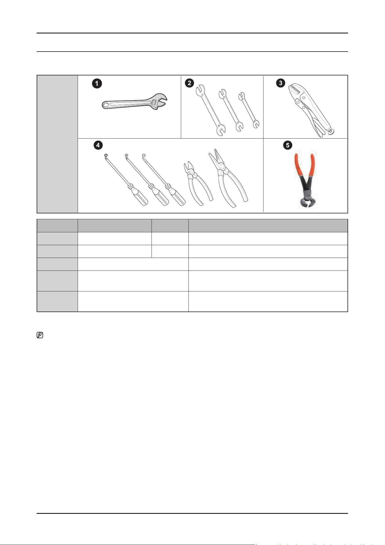
3-1. TOOLS FOR REMOVAL AND REASSEMBLY
Tool image
No. Tool Type Remarks
① Adjustable Wrench
② Open-end Wrench 1-7/16”
③ Vice Pliers
④
Others
(Screwdriver, nipper, long nose pliers)
Common tools for servicing
Screwdriver – Phillip, Flat, Torx T15
⑤ Ear clamping tool
In reassembling of the clamp-bend(ear clamp)
using our SVC part, this tool is needed.
Preparation for parts replacement
1. Remove the residual water inside the product. (Drain the water by operating the drain pump)
2. Close the water supply valve.
3. Turn off the power & disconnect the power cable.
You must turn off the circuit breaker connected to the product.
4. Pull out the unit from the sink and lay it on the oor.
Be careful of the drain hose when pulling out the unit.
5. For materials and repair information related to self-repair, refer to the web site : www.samsung.com/support/
Disassembly and Reassembly _ 19
SAMSUNG PROPRIETARY. DO NOT COPY OR DISTRIBUTE WITHOUT PERMISSION
SAMSUNG PROPRIETARY. DO NOT COPY OR DISTRIBUTE WITHOUT PERMISSION
3-2. STANDARD DISASSEMBLY DRAWINGS
Throughout this manual, features and appearance may vary from you model.
WARNING
Always disconnect the electric power supply & water supply before servicing.
CAUTION
Before servicing,
- Make sure to remove all items including baskets inside dishwasher.
- Uninstall the dishwasher from the furniture cabinet except simple work.
- Drain the water in the dishwasher and disconnect the power supply.
- Disconnect the Inlet & Drain hoses from the duct, if the hoses are too short to pull the dishwasher out of the furniture
cabinet enough.
- Make sure to remove any remaining water in the Sump and hoses by rag or vacuum.
There is a risk of water spill on the oor.
NOTE :
All voltage checks should be made with a voltmeter having a full scale range of 250 volts or higher.
After service is completed, be sure all safety grounding circuits are complete, all electrical connections are secure, and all access panels
are in place.
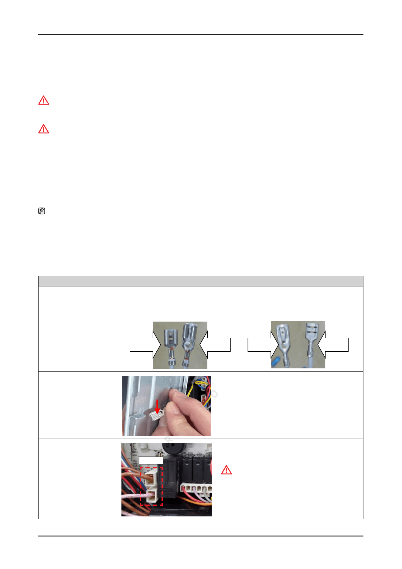
3-2-1. PRECAUTION
Parts Photo Description
Terminal
• Fasten type
• P-Lock type
This dishwasher use 2 kinds terminal type.
-
Fasten type for PBA's heater relay wire terminal. (High current Part)
-
P-Lock type for the other wire terminals.
Fasten type
P-Lock type
P-Lock type
Fasten type
Remove the Terminal
• P-Lock type
Press the buckle, and pull out the terminal.
Remove the Terminal
• Fasten type
PCB
Fasten type is very fastened to each connector.
CAUTION
When release the fasten type, should be care-
ful. This fasten type terminal has a protrusion in
terminal head. So, It may be harder to release the
connector than p-lock type.
20 _ Disassembly and Reassembly
SAMSUNG PROPRIETARY. DO NOT COPY OR DISTRIBUTE WITHOUT PERMISSION
SAMSUNG PROPRIETARY. DO NOT COPY OR DISTRIBUTE WITHOUT PERMISSION
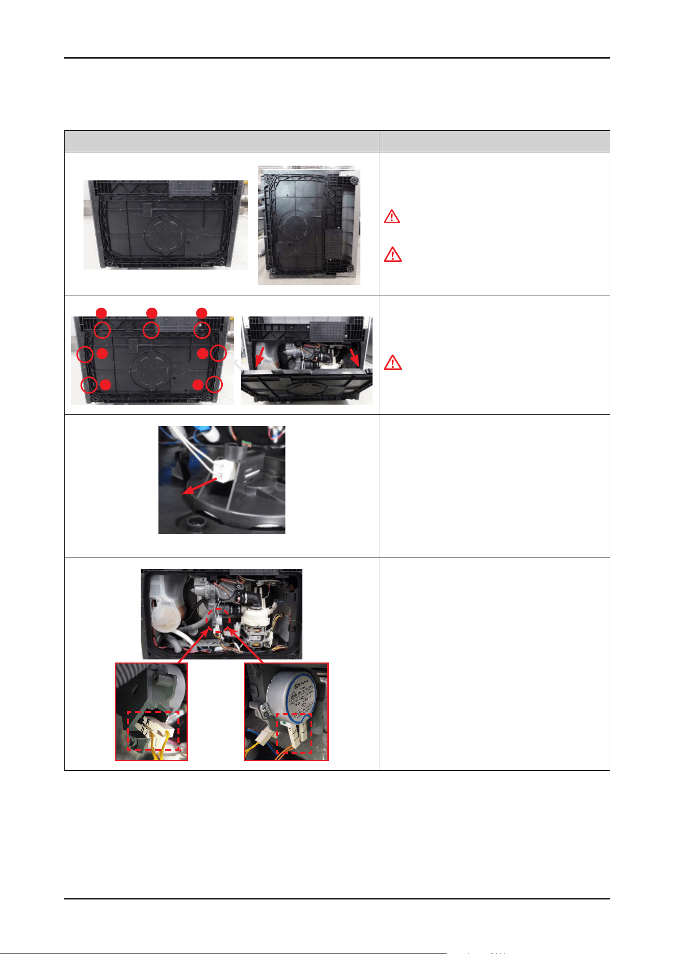
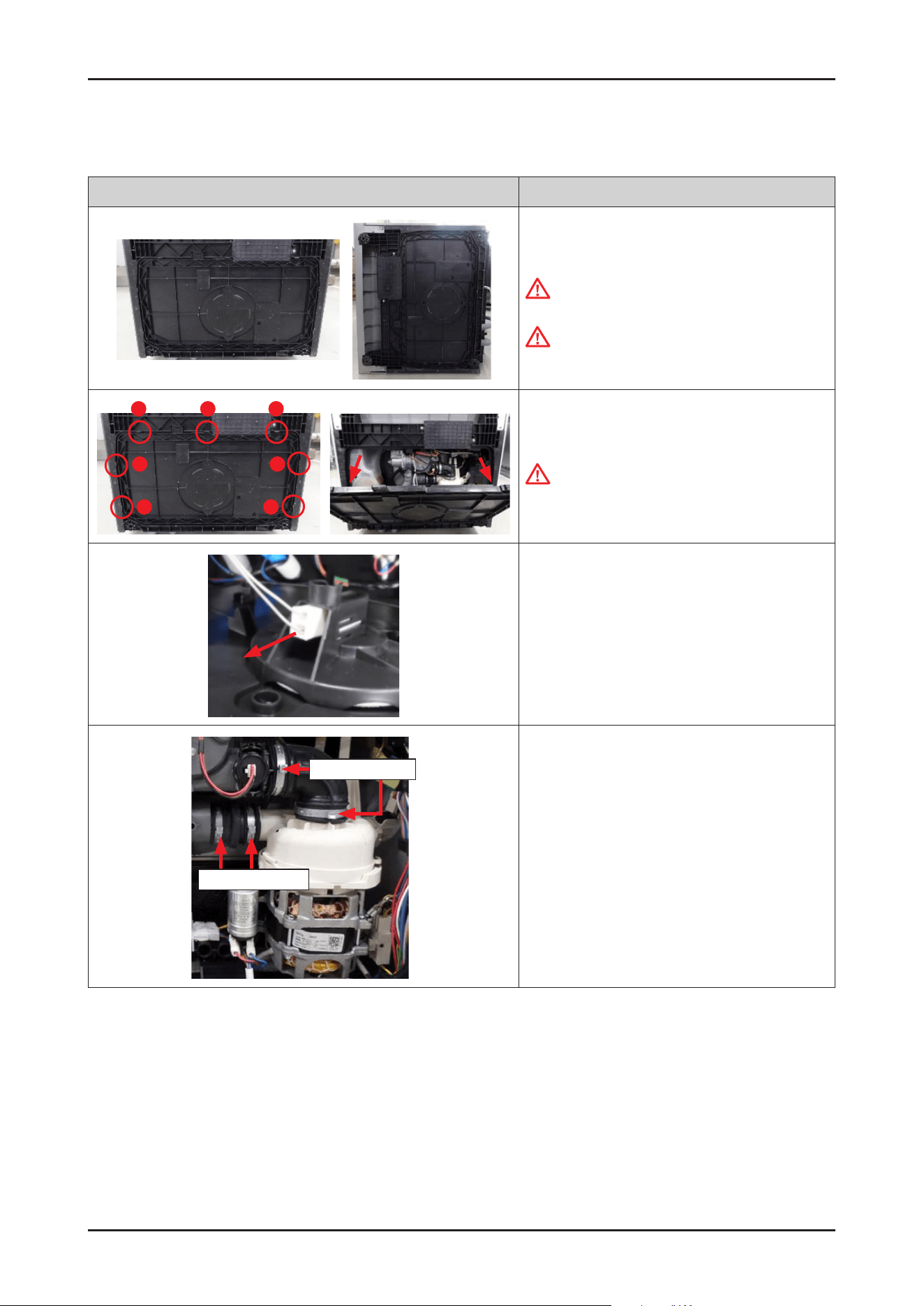
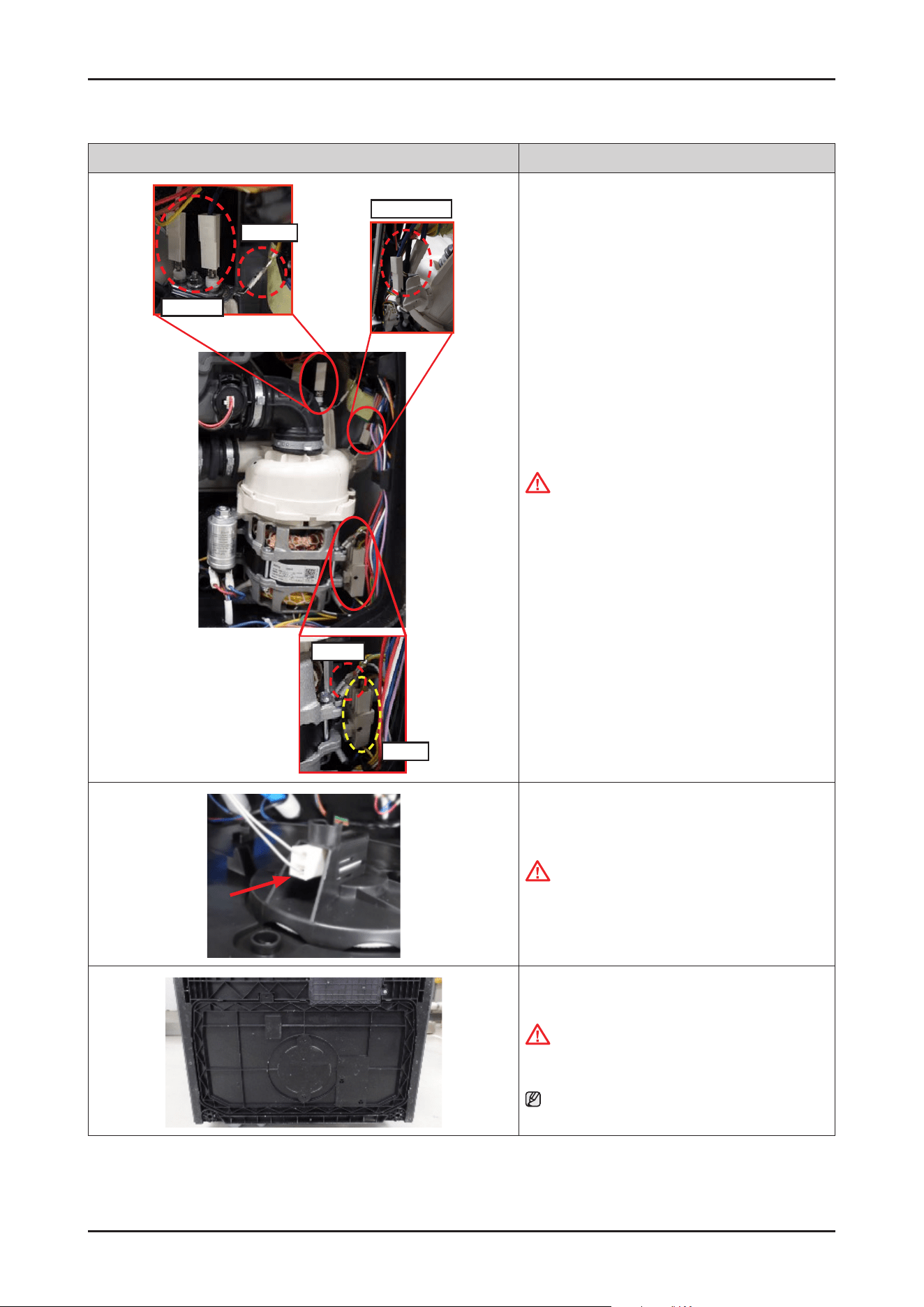
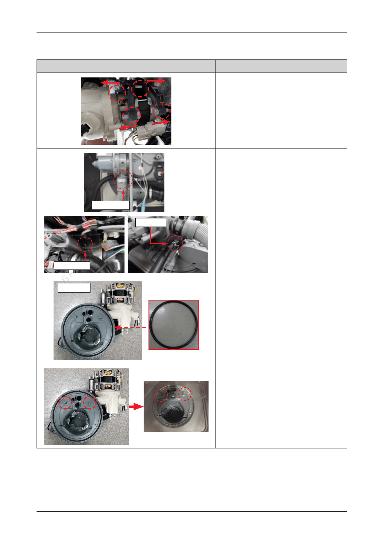
3-2-2. DISTRIBUTION MOTOR
Photo Description
[DISASSEMBLY]
1. Lay down dishwasher on the back or right side
WARNING
Be sure to remove the power plug before servicing.
CAUTION
Make sure to lay down the dishwasher carefully. If it
falls carelessly, It may cause damage.
1
2
3
4
6
5
7
2. Open the COVER BASE which is closed by 7 hooks with
at-head screwdriver.
CAUTION
Make sure to release hooks carefully. It can be brake
easily if it’s opened carelessly.
※ Push up the hook.
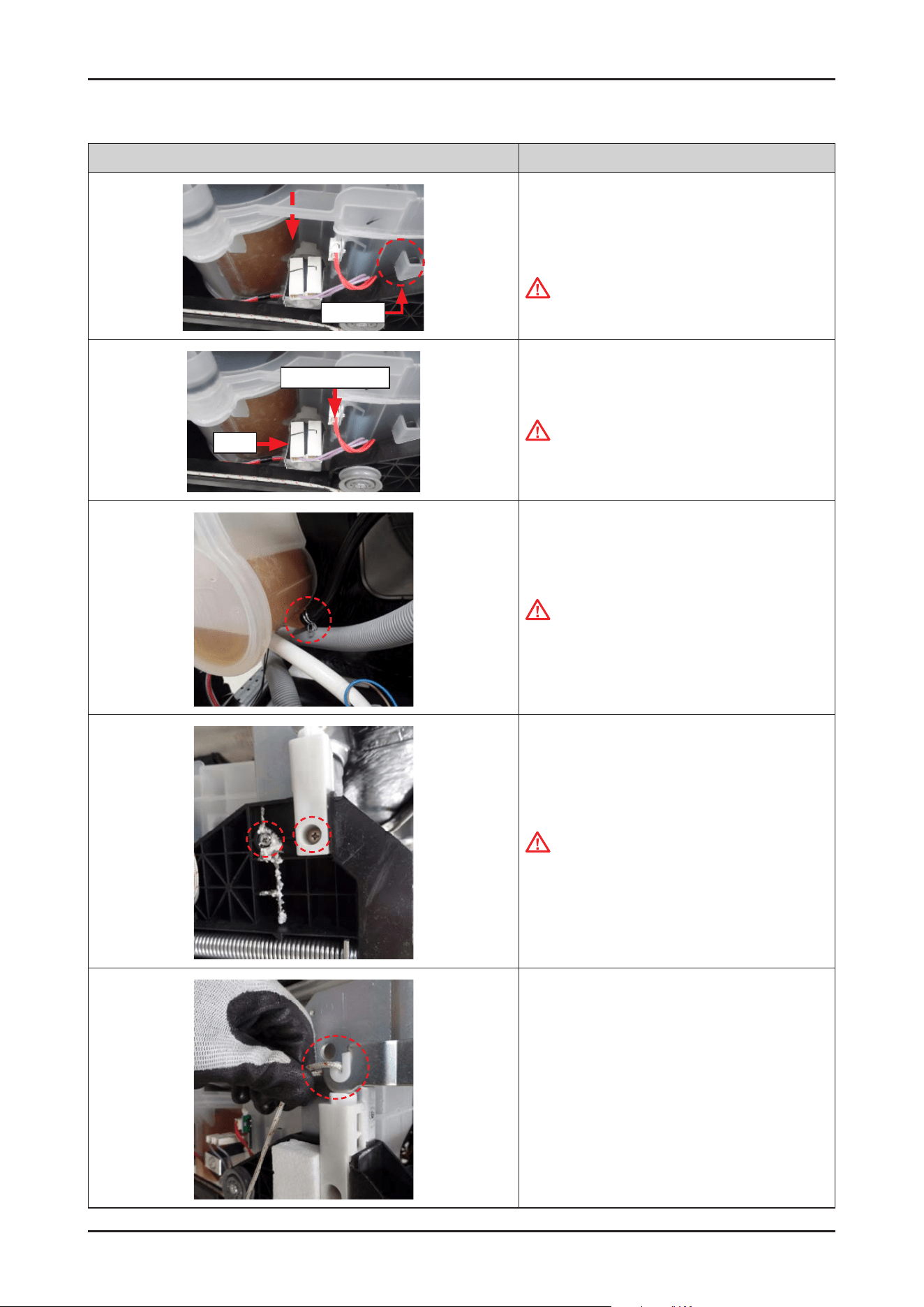
3. Remove the leakage sensor from the COVER BASE.
4. Remove 2 terminals of DISTRIBUTION
MOTOR(ORANGE) and 2 terminals of
MICRO SWITCH(YELLOW).
Disassembly and Reassembly _ 21
SAMSUNG PROPRIETARY. DO NOT COPY OR DISTRIBUTE WITHOUT PERMISSION
SAMSUNG PROPRIETARY. DO NOT COPY OR DISTRIBUTE WITHOUT PERMISSION
Photo Description
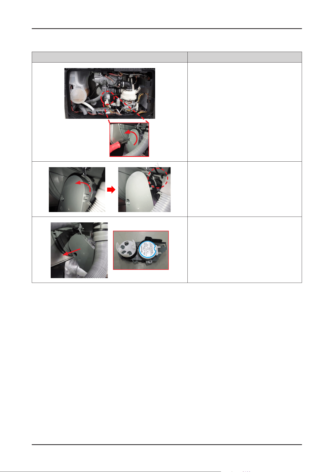
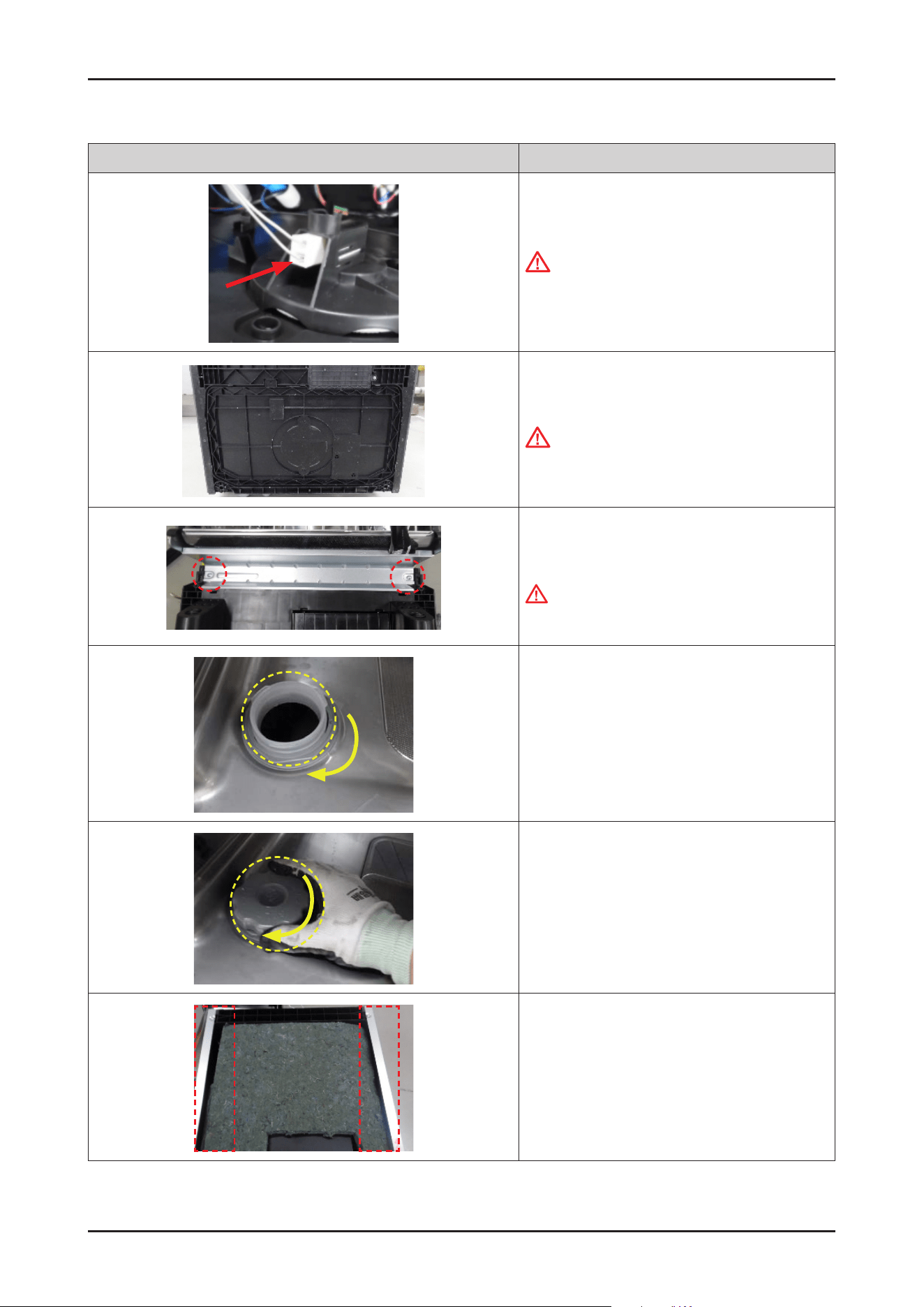
5. Remove 1 screw to take off DISTRIBUTION MOTOR
assembly. Use a short Phillips screwdriver because
there’s a small space to release the screw.
6. Rotate DISTRIBUTION MOTOR assembly to counter-
clockwise direction to release hook.
7. Pull out the DISTRIBUTION MOTOR assembly from the
SUMP.
22 _ Disassembly and Reassembly
SAMSUNG PROPRIETARY. DO NOT COPY OR DISTRIBUTE WITHOUT PERMISSION
SAMSUNG PROPRIETARY. DO NOT COPY OR DISTRIBUTE WITHOUT PERMISSION
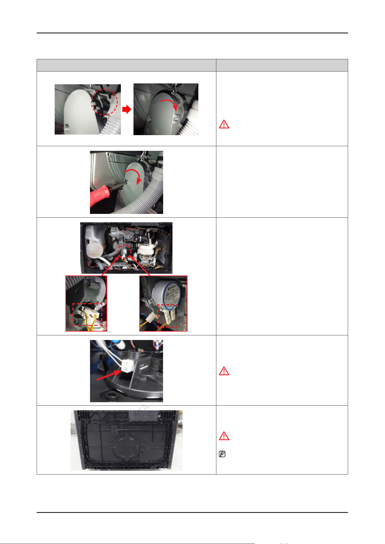
Photo Description
[ASSEMBLY]
1. Fit the DISTRIBUTION MOTOR assembly into the SUMP,
and rotate the assembly in a clockwise direction to lock
the hook.
CAUTION
Make sure to t the assembly to hook to prevent
water leakage.
2. Fasten 1 screw to assemble the motor assembly. Use
a short Phillips screwdriver because there’s a small
space to release the screw.
3. Connect 2 terminals of DISTRIBUTION
MOTOR(ORANGE) and 2 terminals of
MICRO SWITCH(YELLOW).
4. Connect the leakage sensor to the COVER BASE.
CAUTION
Make sure the Wire harness is not getting stuck in
other parts.
5. Assemble the COVER BASE.
CAUTION
Pay attention to the hooks not to broken.
NOTE
Assembly of Base starts from the back.
Disassembly and Reassembly _ 23
SAMSUNG PROPRIETARY. DO NOT COPY OR DISTRIBUTE WITHOUT PERMISSION
SAMSUNG PROPRIETARY. DO NOT COPY OR DISTRIBUTE WITHOUT PERMISSION
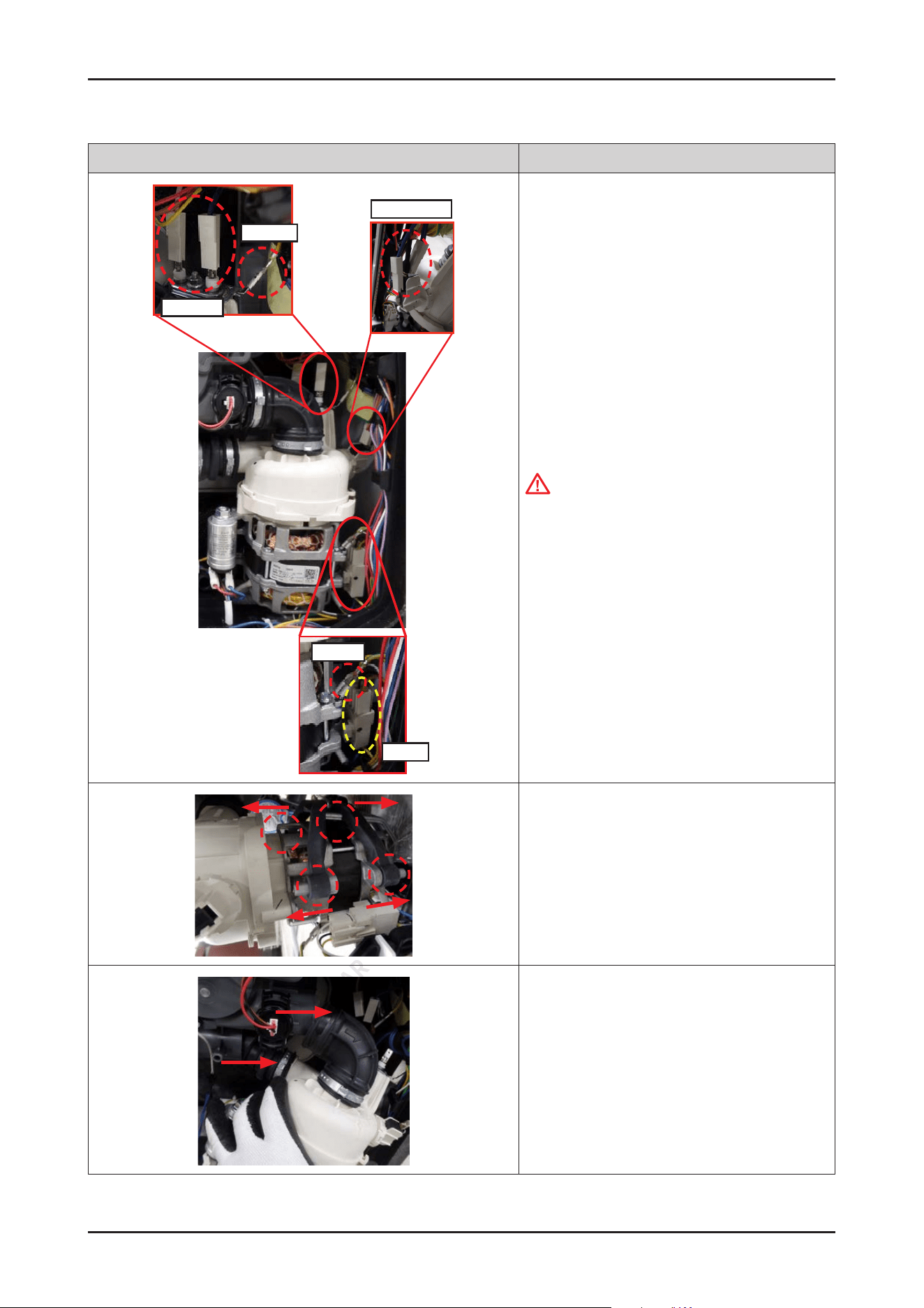
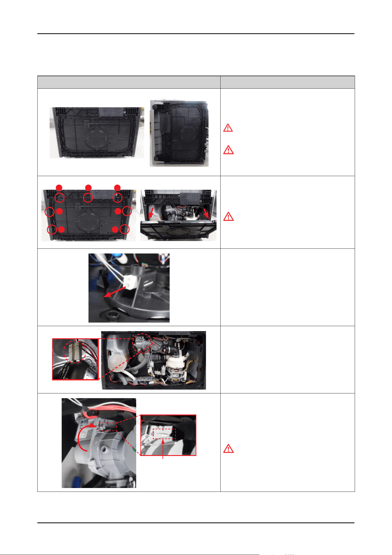
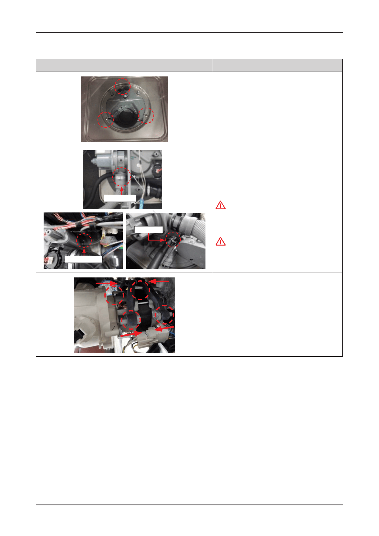
3-2-3. CIRCULATION PUMP / HEATER
Photo Description
[DISASSEMBLY]
1. Lay down dishwasher on the back or right side.
WARNING
Be sure to remove the power plug before servicing.
CAUTION
Make sure to lay down the dishwasher carefully. If it
falls carelessly, It may cause damage.
1
2
3
4
6
5
7
2. Open the COVER BASE which is closed by 7 hooks
with at-head screwdriver.
CAUTION
Make sure to release hooks carefully.
It can be brake easily if it’s opened carelessly.
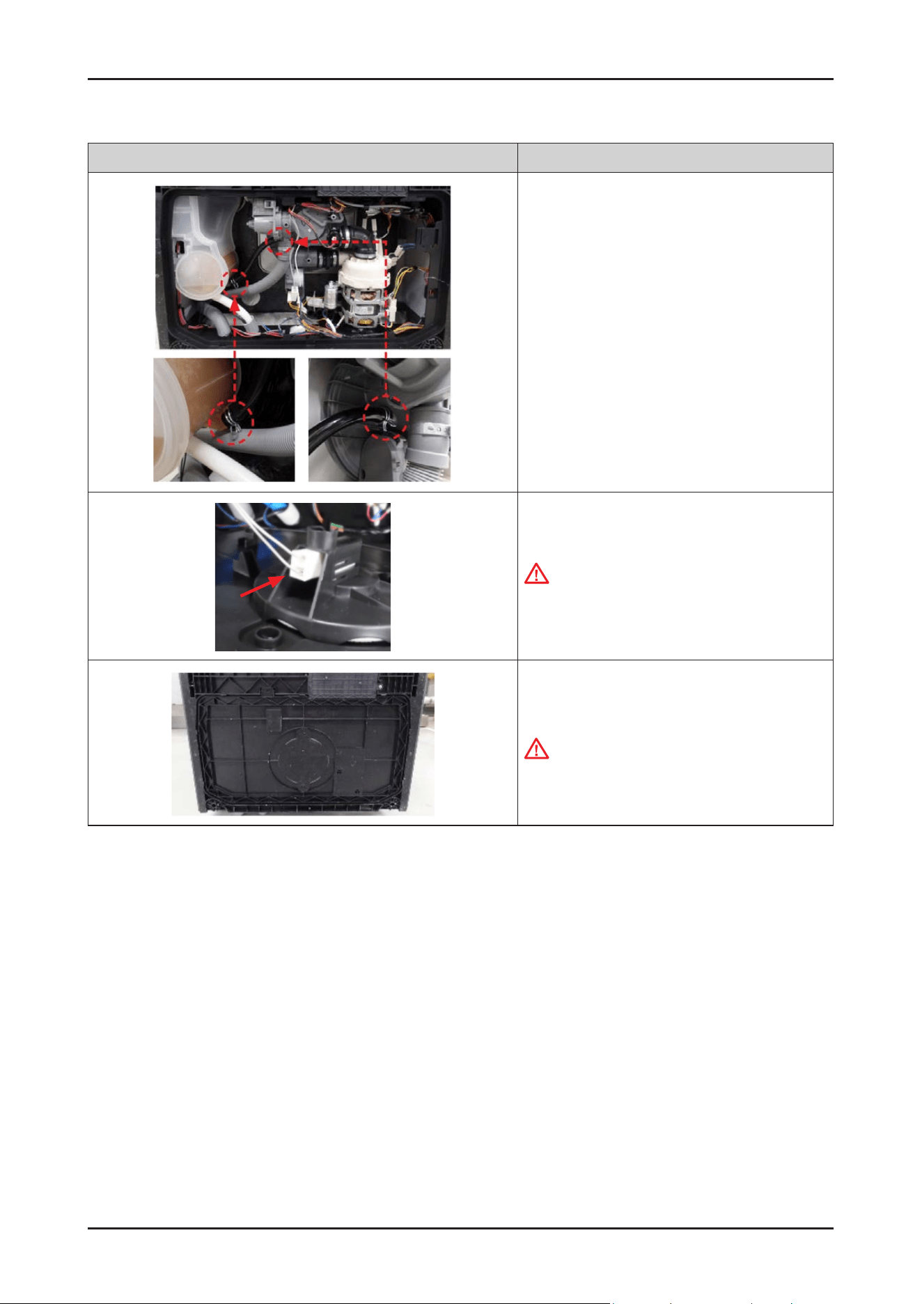
3. Remove the leakage sensor from
the COVER BASE.
CLAMPER HOSE IN
CAMPER HOSE OUT
4. Remove the clamps for xing MOTOR PUMP
assembly.
- DD81-02481A: SVC-CLAMPER HOSE OUT
- DD81-02482A: SVC-CLAMPER HOSE IN
24 _ Disassembly and Reassembly
SAMSUNG PROPRIETARY. DO NOT COPY OR DISTRIBUTE WITHOUT PERMISSION
SAMSUNG PROPRIETARY. DO NOT COPY OR DISTRIBUTE WITHOUT PERMISSION
Photo Description
Heater
Ground
Ground
Pump
Micro Switch
5. Remove the wire connectors for HEATER and
CIRCULATION PUMP.
CAUTION
Do not forced to remove the wire connectors.
Release hooks carefully to remove the wire.
6. Remove the rubber from the pump assembly.
(4 points)
7. Pull out the MOTOR PUMP assembly from the SUMP.
Disassembly and Reassembly _ 25
SAMSUNG PROPRIETARY. DO NOT COPY OR DISTRIBUTE WITHOUT PERMISSION
SAMSUNG PROPRIETARY. DO NOT COPY OR DISTRIBUTE WITHOUT PERMISSION
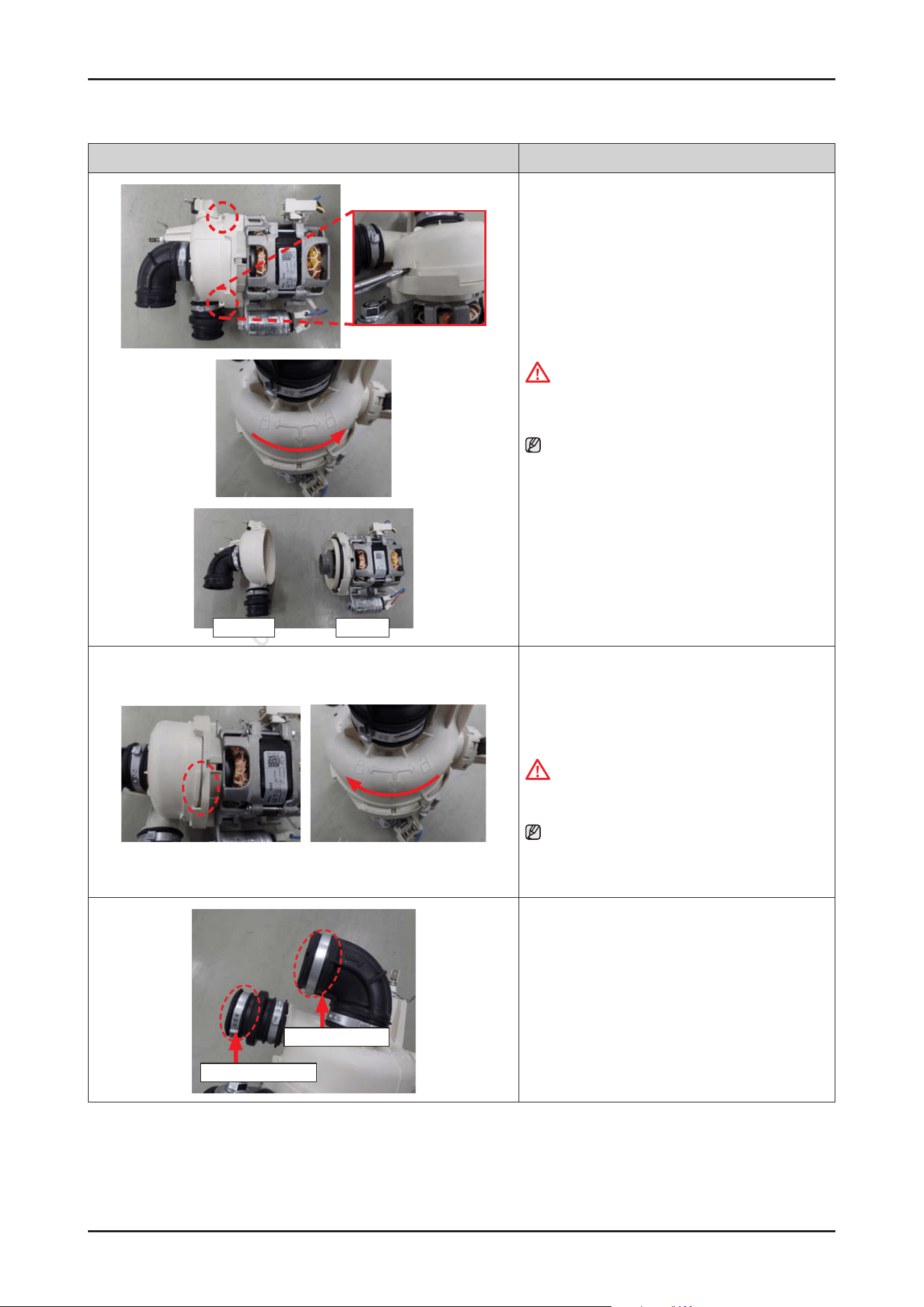
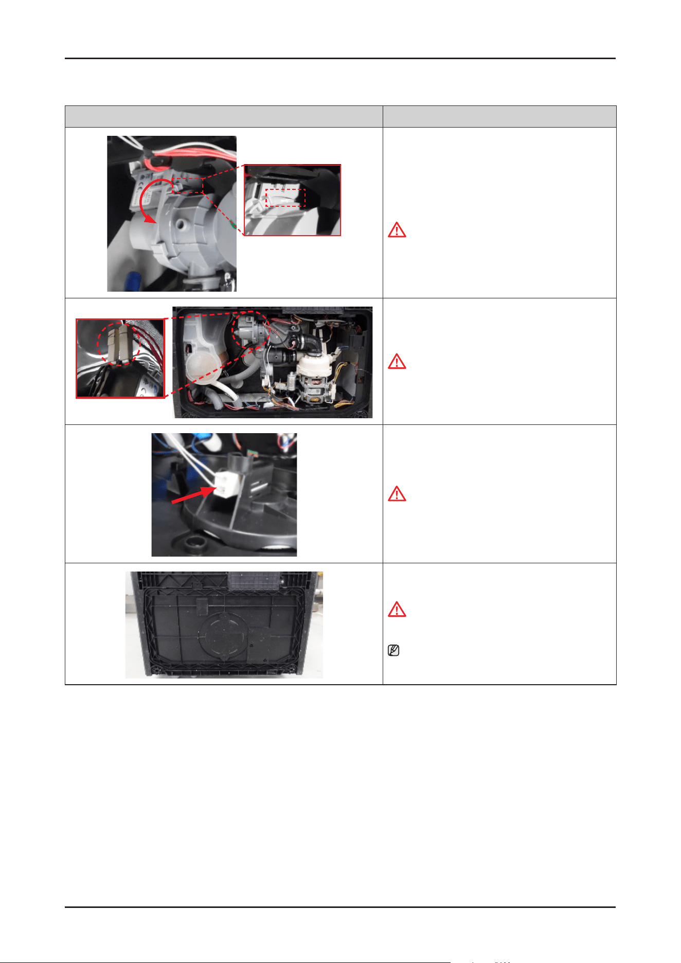
Photo Description
HEATER PUMP
8. Disassemble the CIRCULATION PUMP from the
HEATER assembly by rotating it counter-clockwise.
CAUTION
Make sure to release hooks carefully. It can be
broken easily if it’s bent carelessly.
NOTE :
Circulation pump and heater will serviced to
assembly (DD82-01733A/SVC MOTOR-PUMP) only
because it’s too hard to service each part separately.
[ASSEMBLY]
1. Assemble the CIRCULATION PUMP with the HEATER
assembly by rotating it clockwise.
CAUTION
Make sure to tighten the hooks securely to prevent
water leakage.
NOTE :
Circulation pump and heater will serviced to
assembly (DD82-01733A/SVC MOTOR-PUMP) only
because it’s too hard to service each part separately.
CLAMPER HOSE OUT
CLAMPER HOSE IN
2. Fit the Ear Clamps on each hoses.
- DD81-02481A: SVC-CLAMPER HOSE OUT
- DD81-02482A: SVC-CLAMPER HOSE IN
26 _ Disassembly and Reassembly
SAMSUNG PROPRIETARY. DO NOT COPY OR DISTRIBUTE WITHOUT PERMISSION
SAMSUNG PROPRIETARY. DO NOT COPY OR DISTRIBUTE WITHOUT PERMISSION
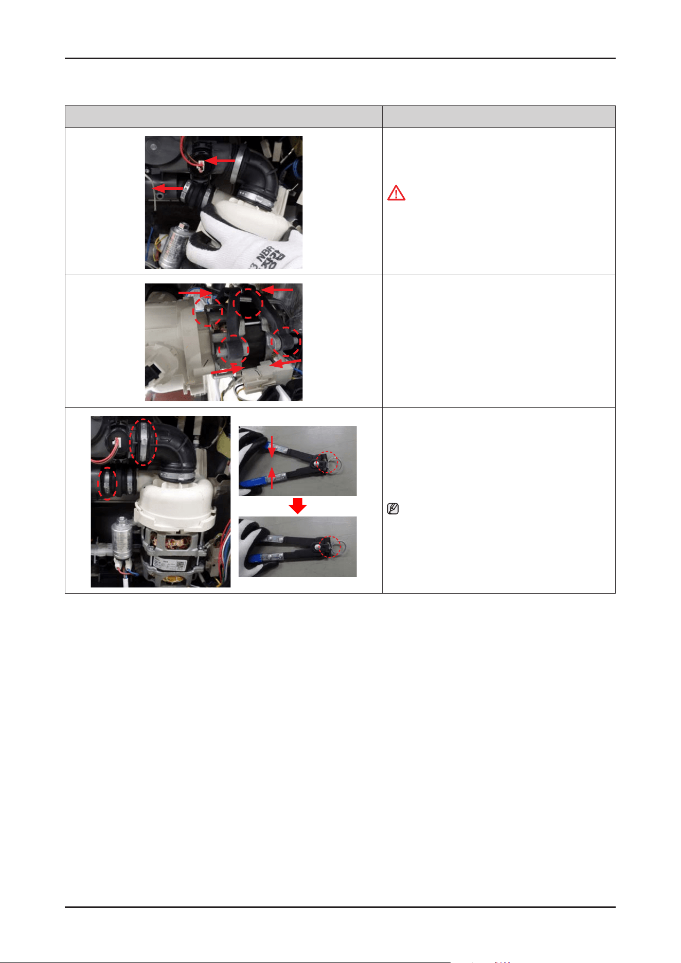
Photo Description
3. Fit the MOTOR PUMP assembly into the SUMP.
CAUTION
Make sure to insert the hoses correctly.
There's risks of leakage or poor performance when
it’s disassembled.
4. Assemble the MOTOR PUMP with the DAMPER
PUMP.
5. Fasten the Ear clamps using Clamping Pliers.
NOTE :
Refer to the left image to fasten the Ear clamp.
Disassembly and Reassembly _ 27
SAMSUNG PROPRIETARY. DO NOT COPY OR DISTRIBUTE WITHOUT PERMISSION
SAMSUNG PROPRIETARY. DO NOT COPY OR DISTRIBUTE WITHOUT PERMISSION
Photo Description
Heater
Ground
Ground
Pump
Micro Switch
6. Connect the wire terminals for heater and
CIRCULATION PUMP.
CAUTION
Make sure the Wire harness is not getting stuck in
other parts.
7. Connect the leakage sensor to the COVER BASE.
CAUTION
Make sure the Wire harness is not getting stuck in
other parts
8. Assemble the COVER BASE.
CAUTION
Pay attention to the hooks not to break
NOTE : Assembly of Base starts from the back.
28 _ Disassembly and Reassembly
SAMSUNG PROPRIETARY. DO NOT COPY OR DISTRIBUTE WITHOUT PERMISSION
SAMSUNG PROPRIETARY. DO NOT COPY OR DISTRIBUTE WITHOUT PERMISSION
3-2-4. DRAIN PUMP
Photo Description
[DISASSEMBLY]
1. Lay down dishwasher on the back or left side.
WARNING
Be sure to remove the power plug before servicing.
CAUTION
Make sure to lay down the dishwasher carefully.
If it falls carelessly, It may cause damage.
1
2
3
4
6
5
7
2. Open the COVER BASE which is closed by 7 hooks with
at-head screwdriver.
CAUTION
Make sure to release hooks carefully. It can be brake
easily if it’s opened carelessly
3. Remove the leakage sensor from the COVER BASE.
4. Remove 2 wire connectors(Fasten type) of DRAIN
PUMP.
Hold on the hook
5. Hold on the hook with a at-head screwdriver and
remove the DRAIN PUMP by rotating it counter-
clockwise
CAUTION
It may spill the water from the SUMP.
Place some towels or rags under the SUMP.
Disassembly and Reassembly _ 29
SAMSUNG PROPRIETARY. DO NOT COPY OR DISTRIBUTE WITHOUT PERMISSION
SAMSUNG PROPRIETARY. DO NOT COPY OR DISTRIBUTE WITHOUT PERMISSION
Photo Description
[ASSEMBLY]
1. Assemble the DRAIN PUMP with the SUMP by rotating
it clockwise.
CAUTION
Make sure to t the hook securely to prevent water
leakage.
2. Connect the 2 DRAIN PUMP wire connectors.
CAUTION
Make sure the Wire harness is not getting stuck in
other parts.
3. Connect the leakage sensor to the COVER BASE.
CAUTION
Make sure the Wire harness is not getting stuck in
other parts.
4. Assemble the COVER BASE.
CAUTION
Be careful not to break the hooks.
NOTE
Assembly of Base starts from the back.
30 _ Disassembly and Reassembly
SAMSUNG PROPRIETARY. DO NOT COPY OR DISTRIBUTE WITHOUT PERMISSION
SAMSUNG PROPRIETARY. DO NOT COPY OR DISTRIBUTE WITHOUT PERMISSION
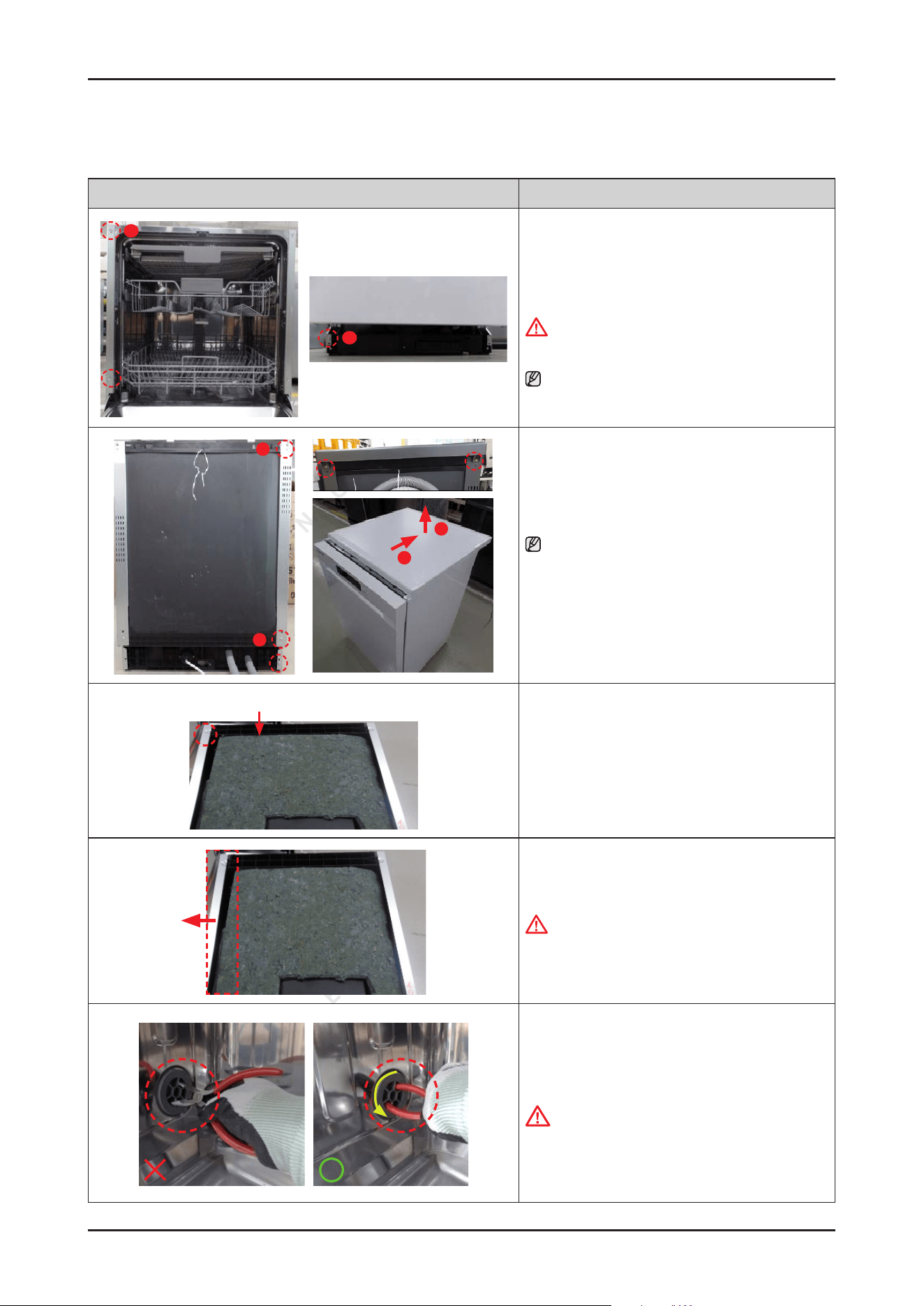
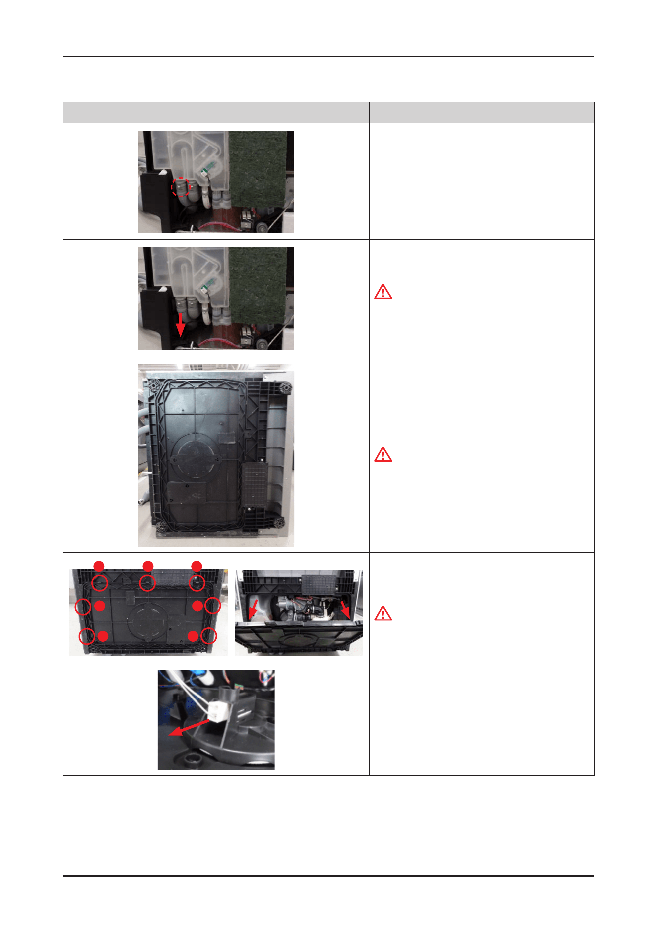
3-2-5. CASE BRAKE / CAP CASE BRAKE / GASKET BRAKE
Photo Description
A
B
[DISASSEMBLY]
1. Remove 3 screws that connect left SIDE PANEL to
front side of dishwasher.
WARNING
Be sure to remove the power plug before servicing.
NOTE :
In case of Free Standing models, there's no screws of
type B.
C
B
2
1
2.
Remove 3 screws at the back side of dishwasher.
NOTE :
In case of Free Standing models, take off the COVER
TOP by removing 2 screws of type A.
After removing screws, pull the COVER TOP backward
rst, and take it off upward.
Guide Tub Top
3. Remove 1 screw at the left side of GUIDE TUB TOP.
-
Screw: DD81-02694A / 1 pc
4. Remove the left SIDE PANEL.
WARNING
Do not do this work without safety gloves. It may
cause injury from sharp edges.
5. Take off the CAP CASE BRAKE by rotating in
a counter-clockwise direction with long-nose
pliers.
-
CAP CASE BRAKE : DD81-02725A
CAUTION
It can brake easily when you use the iron part of the
pliers.
Take off the cap using the handle part of the pliers
to prevent damage.
Disassembly and Reassembly _ 31
SAMSUNG PROPRIETARY. DO NOT COPY OR DISTRIBUTE WITHOUT PERMISSION
SAMSUNG PROPRIETARY. DO NOT COPY OR DISTRIBUTE WITHOUT PERMISSION
Photo Description
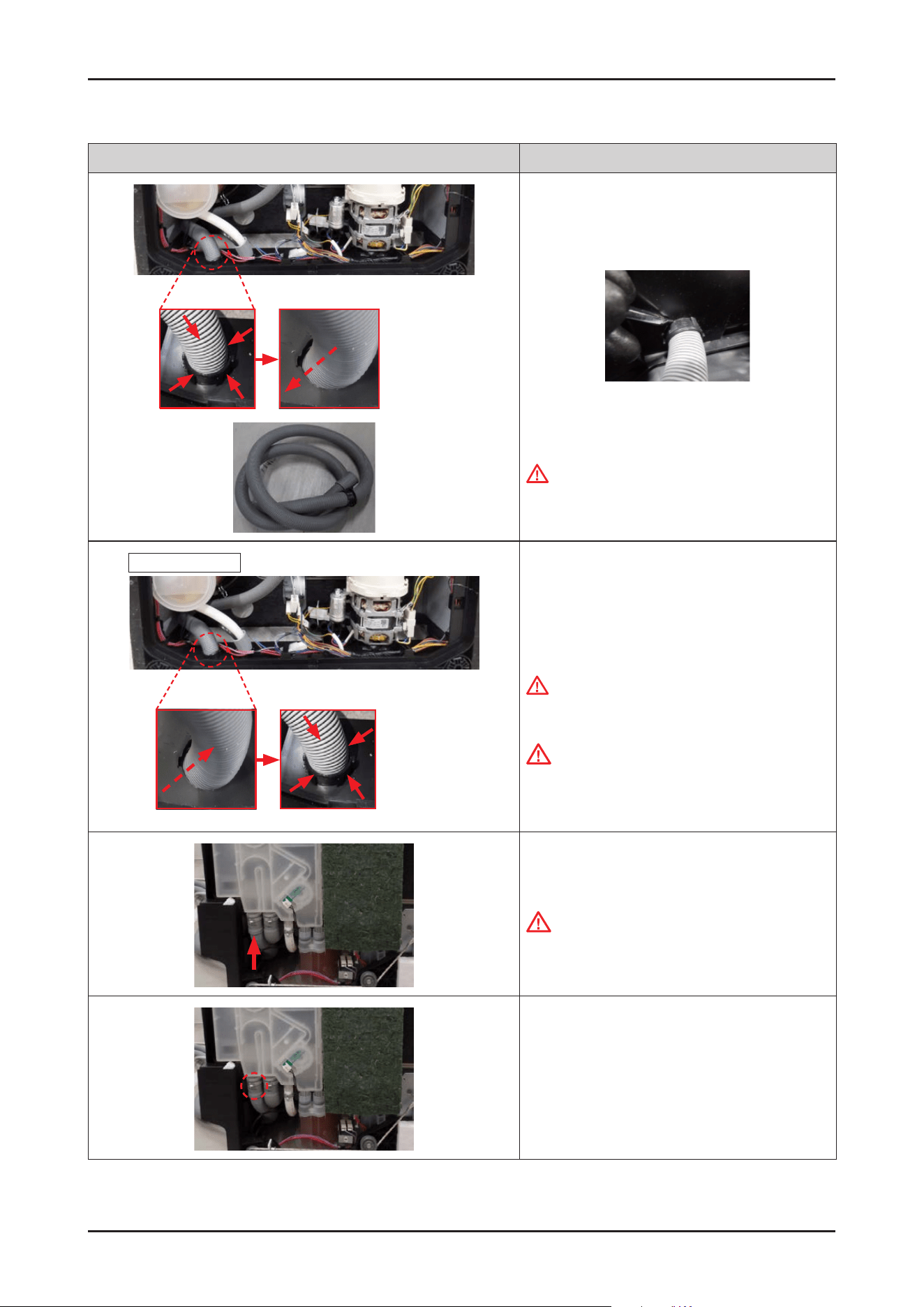
Gasket brake
6 Remove the GASKET BRAKE from the CASE BRAKE
assembly
Hook
7. Remove the wire connector of the owmeter.
CAUTION
It can be removed the connector easily with
unhooking.
A
B
8. Unclip the clamps downward enough.
CAUTION
Make sure to match the hoses to correct outlets of
CASE BRAKE when they are reassembled.
Case brake
Cap Case
brake
Gasket
brake
9. Remove/separate the CASE BRAKE from the hoses
and water softener.
CAUTION
It may spill the water from the hoses and CASE
BRAKE.
Place some towels or rags under the CASE BRAKE.
Tips for removing and reassembling hoses from the
outlet : the force should be applied aligned with the
outlet direction, with small rotation of the hose.
(not bending to sides or twisting)
32 _ Disassembly and Reassembly
SAMSUNG PROPRIETARY. DO NOT COPY OR DISTRIBUTE WITHOUT PERMISSION
SAMSUNG PROPRIETARY. DO NOT COPY OR DISTRIBUTE WITHOUT PERMISSION
Photo Description
Drain hose In
Drain hose
Aqua Stop
[ASSEMBLY]
1. Fit the ear clamps on each hose, and insert the
outlets of CASE BRAKE to hoses and holes of WATER
SOFTENER.
CAUTION
Make sure to match the hoses to correct outlets of
CASE BRAKE when they are reassembled.
It may cause problems when assembling the drain
hoses in reverse.
CAUTION
Make sure to insert the hoses correctly.
There's risks of leakage or poor performance when
it’s misassembled.
2. Fit the GASKET BRAKE on the CASE BRAKE, and fasten
the CAP CASE BRAKE by rotating clockwise direction
with long-nose pliers.
CAUTION
It can brake easily when you use the iron part of the
pliers.
Take off the cap using the handle part of the pliers
to prevent damage.
CAUTION
Pay attention to assemble the seal correctly. It may
cause the water leakage when it’s misassembled.
A
B
3. Fasten the ear clamps.
- Type A: DD81-02910A (ø28.6) / 2 pcs
- Type B: DD81-02911A (ø17.5) / 1 pc
Disassembly and Reassembly _ 33
SAMSUNG PROPRIETARY. DO NOT COPY OR DISTRIBUTE WITHOUT PERMISSION
SAMSUNG PROPRIETARY. DO NOT COPY OR DISTRIBUTE WITHOUT PERMISSION
Photo Description
4. Connect the wire connector of owmeter.
CAUTION
Make sure the wire harness is not getting stuck in
other parts.
5. Assemble the left SIDE PANEL with the screws.
CAUTION
Fasten the screws that were assembled to original
location. Don’t assemble into other locations.
WARNING
Do not do this work without safety gloves. It may
cause injury from sharp edges.
34 _ Disassembly and Reassembly
SAMSUNG PROPRIETARY. DO NOT COPY OR DISTRIBUTE WITHOUT PERMISSION
SAMSUNG PROPRIETARY. DO NOT COPY OR DISTRIBUTE WITHOUT PERMISSION
3-2-6. DRAIN HOSE
Photo Description
A
B
[DISASSEMBLY]
1. Remove 3 screws that connect left SIDE PANEL to
front side of dishwasher.
- Type A: DD81-02693A / 2 pcs
- Type B: DD81-02694A / 1 pc
WARNING
Be sure to remove the power plug before servicing.
NOTE :
In case of Free Standing models, there's no screws of
type B.
C
B
2
1
2. Remove 3 screws at the back side of dishwasher.
- Type C: DD81-02692A / 1 pc
- Type B: DD81-02694A / 2 pcs
NOTE :
In case of Free Standing models, take off the COVER
TOP by removing 2 screws of type A.
After removing screws, pull the COVER TOP backward
rst, and take it off upward.
Guide Tub Top
3.
Remove 1 screw at the left side of GUIDE TUB TOP.
- Screw: DD81-02694A / 1 pc
4. Remove the left SIDE PANEL.
WARNING
Do not do this work without safety gloves. It may
cause injury from sharp edges.
CAUTION
In case of Free Standing models, hook is inserted to
COVER PLINTH.
Release the hook carefully.
Disassembly and Reassembly _ 35
SAMSUNG PROPRIETARY. DO NOT COPY OR DISTRIBUTE WITHOUT PERMISSION
SAMSUNG PROPRIETARY. DO NOT COPY OR DISTRIBUTE WITHOUT PERMISSION
Photo Description
5. Unclip the clamp of drain hose downward enough.
- Clamp: DD81-02910A (ø28.6) / 1 pc
(the 1st one from the left side)
6. Remove the drain hose from the CASE BRAKE.
CAUTION
It may spill the water from the hose and CASE
BRAKE. Place some towels or rags under the CASE
BRAKE.
7. Lay down the dishwasher on the right side.
CAUTION
Make sure to lay down the dishwasher carefully.
If it falls carelessly, it may cause damage.
1
2
3
4
6
5
7
8. Open the COVER BASE which is closed by 7 hooks
using at-head screwdriver.
CAUTION
Make sure to release hooks carefully.
It can brake easily if it’s opened carelessly.
9. Remove the leakage sensor from the COVER BASE.
36 _ Disassembly and Reassembly
SAMSUNG PROPRIETARY. DO NOT COPY OR DISTRIBUTE WITHOUT PERMISSION
SAMSUNG PROPRIETARY. DO NOT COPY OR DISTRIBUTE WITHOUT PERMISSION
Photo Description
10. To remove DRAIN HOSE, pull the hose out backward
while pressing 4 hooks of holder.
When removing the hooks, push in the hooks one by
one using a (-) screwdriver.
11. Pull out DRAIN HOSE carefully.
WARNING
Do not do this work without safety gloves. It may
cause injury from sharp edges.
Inside of BASE
outside
Out to In Hooking
[ASSEMBLY]
1.
Insert the DRAIN HOSE from the outside to inside of
BASE.
WARNING
Do not do this work without safety gloves. It may
cause injury from sharp edges.
CAUTION
Make sure to fasten the hook at the inside of BASE.
2. Fit the ear clamps on the DRAIN HOSE, and insert
the DRAIN HOSE to the outlet of
CASE BRAKE.
CAUTION
Make sure to insert the hoses correctly. There's
risks of leakage or poor performance when it’s
misassembled.
3. Fasten the ear clamp.
-
Clamp: DD81-02910A (ø28.6) / 1 pc
Disassembly and Reassembly _ 37
SAMSUNG PROPRIETARY. DO NOT COPY OR DISTRIBUTE WITHOUT PERMISSION
SAMSUNG PROPRIETARY. DO NOT COPY OR DISTRIBUTE WITHOUT PERMISSION
Photo Description
4. Assemble the left SIDE PANEL and COVER BASE.
WARNING
Do not do this work without safety gloves. It may
cause injury from sharp edges.
CAUTION
Fasten the screws that were assembled to original
location. Don’t assemble into other locations.
CAUTION
Pay attention to the hooks not to broken.
NOTE :
Assembly of Base starts from the back.

38 _ Disassembly and Reassembly
SAMSUNG PROPRIETARY. DO NOT COPY OR DISTRIBUTE WITHOUT PERMISSION
SAMSUNG PROPRIETARY. DO NOT COPY OR DISTRIBUTE WITHOUT PERMISSION
3-2-7. AQUA STOP
Photo Description
[DISASSEMBLY]
1.
Remove the left SIDE PANEL.
WARNING
Be sure to remove the power plug before servicing.
WARNING
Do not do this work without safety gloves. It may
cause injury from sharp edges.
CAUTION
In case of Free Standing models, hook is inserted to
COVER PLINTH. Release the hook carefully.
2. Unclip the clamp of AQUA STOP downward enough.
- Clamp: DD81-02911A(ø17.5) /1 pc
(the 3rd one from the left side)
3. Remove / separate the AQUA STOP from the CASE
BRAKE.
CAUTION
It may spill the water from the hose and CASE
BRAKE. Place some towels or rags under the CASE
BRAKE.
4. Lay down the dishwasher on the right side.
CAUTION
Make sure to lay down the dishwasher carefully.
If it falls carelessly, it may cause damage.
1
2
3
4
6
5
7
5. Open the COVER BASE which is closed by 7 hooks
with at-head screwdriver.
CAUTION
Make sure to release hooks carefully.
It can brake easily if it’s opened carelessly.
Disassembly and Reassembly _ 39
SAMSUNG PROPRIETARY. DO NOT COPY OR DISTRIBUTE WITHOUT PERMISSION
SAMSUNG PROPRIETARY. DO NOT COPY OR DISTRIBUTE WITHOUT PERMISSION
Photo Description
6. Remove the leakage sensor from the COVER BASE.
7. Remove the wire connector of AQUA STOP.
8. To remove AQUA STOP, pull the hose out backward
while pressing 4 hooks of holder.
9.
Pull out AQUA STOP carefully.
WARNING
Do not do this work without safety gloves. It may
cause injury from sharp edges.
Inside of BASE
Outside
Out to In Hooking
[ASSEMBLY]
1.
Insert the AQUA STOP from the outside to inside of
BASE.
CAUTION
Make sure to fasten the hook at the inside of BASE.
WARNING
Do not do this work without safety gloves. It may
cause injury from sharp edges.
2. Connect the wire connector of AQUA STOP.
CAUTION
Make sure the Wire harness is not getting stuck in
other parts.
40 _ Disassembly and Reassembly
SAMSUNG PROPRIETARY. DO NOT COPY OR DISTRIBUTE WITHOUT PERMISSION
SAMSUNG PROPRIETARY. DO NOT COPY OR DISTRIBUTE WITHOUT PERMISSION
Photo Description
3. Fit the ear clamps on the AQUA STOP, and insert the
hose to the outlet of CASE BRAKE.
CAUTION
Make sure to insert the hoses correctly.
There's risks of leakage or poor performance when
it’s misassembled.
4. Fasten the ear clamp.
- Clamp: DD81-02911A(ø17.5) / 1 pc
5. Assemble the left SIDE PANEL and COVER BASE.
WARNING
Do not do this work without safety gloves. It may
cause injury from sharp edges.
CAUTION
Fasten the screws that were assembled to original
location. Don’t assemble into other locations.
CAUTION
Be careful not to break the hooks.
Disassembly and Reassembly _ 41
SAMSUNG PROPRIETARY. DO NOT COPY OR DISTRIBUTE WITHOUT PERMISSION
SAMSUNG PROPRIETARY. DO NOT COPY OR DISTRIBUTE WITHOUT PERMISSION
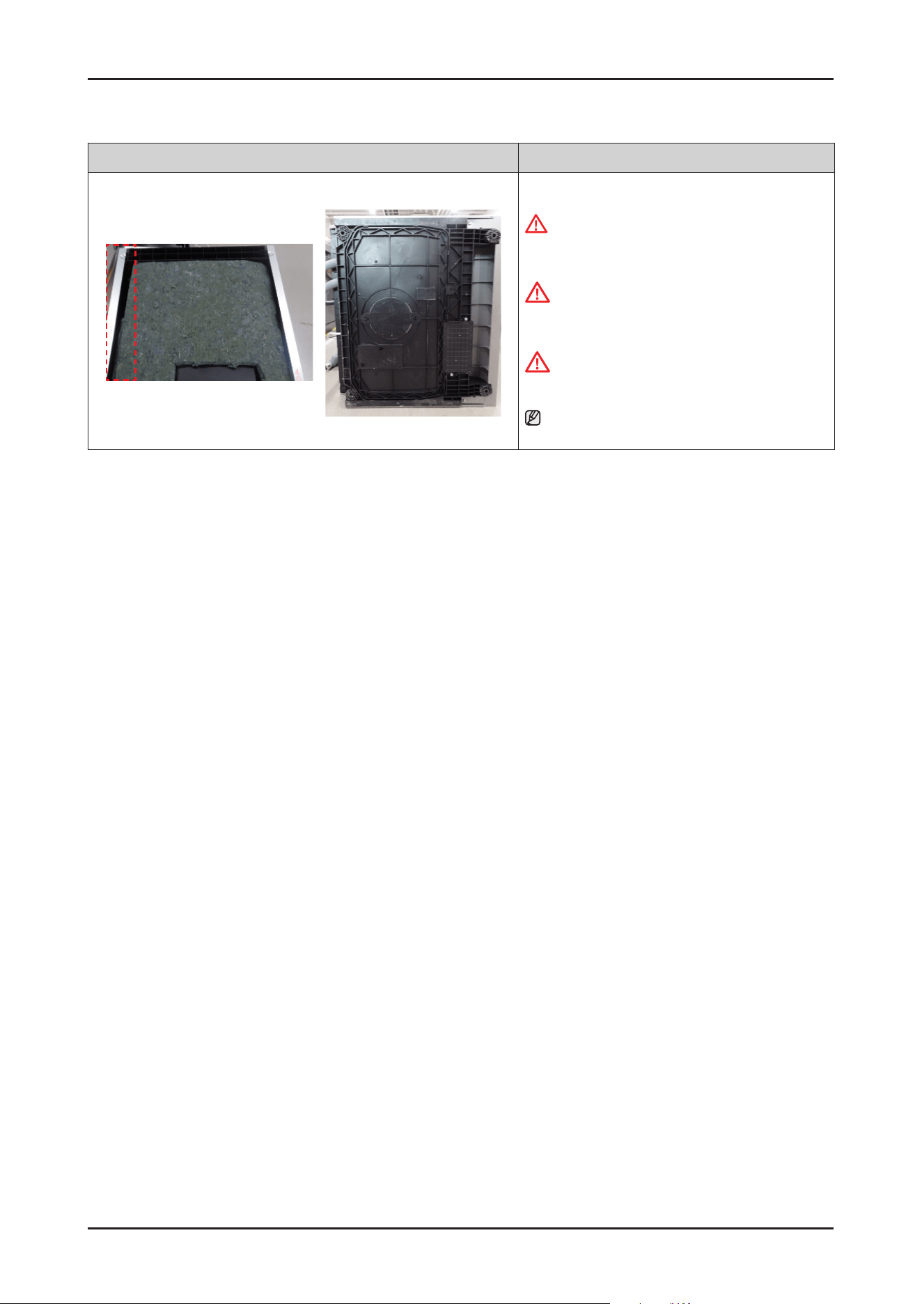
3-2-8. WATER SOFTENER / FRAME FRONT
Photo Description
[DISASSEMBLY]
1. Release the SOFTENER CAP by rotating to counter-
clockwise.
-
SOFTENER CAP : DD81-02918A
WARNING
Be sure to remove the power plug before servicing
2. Release the SOFTENER HOLDER by rotating in a
counter-clockwise.
CAUTION
Be careful to not damage inner parts to release the
SOFTENER HOLDER by tools.
-
SOFTENER HOLDER: DD81-02919A
A
B
3. Remove 6 screws that connect SIDE PANELs to front
side of dishwasher.
-
Type A: DD81-02693A / 4 pcs
-
Type B: DD81-02694A / 2 pcs
NOTE :
In case of Free Standing models, only need to remove
type A.
A
B
2
1
4. Remove 6 screws at the back side of dishwasher.
-
Type A: DD81-02692A / 2 pcs
-
Type B: DD81-02694A / 4 pcs
NOTE :
In case of Free Standing models, take off the COVER
TOP by removing 2 screws of type A.
After removing screws, pull the COVER TOP backward
rst, and take it off upward.
Guide Tub Top
5. Remove 2 screws at the left side of GUIDE TUB TOP.
- Screw: DD81-02694A / 2 pcs
WARNING
Don't leave heavy weight Items on the set.
42 _ Disassembly and Reassembly
SAMSUNG PROPRIETARY. DO NOT COPY OR DISTRIBUTE WITHOUT PERMISSION
SAMSUNG PROPRIETARY. DO NOT COPY OR DISTRIBUTE WITHOUT PERMISSION
Photo Description
6. Take off the SIDE PANELs.
WARNING
Do not do this work without safety gloves. It may
cause injury from sharp edges.
CAUTION
Using an electric screwdriver may cause wear
and tear, so it is recommended to use an electric
screwdriver after gently loosening it manually.
Frame front
7. Remove 2 machine screws and take off the FRAME
FRONT.
-
Machine Screws: DD81-02728A
WARNING
Do not do this work without safety gloves. It may
cause injury from sharp edges.
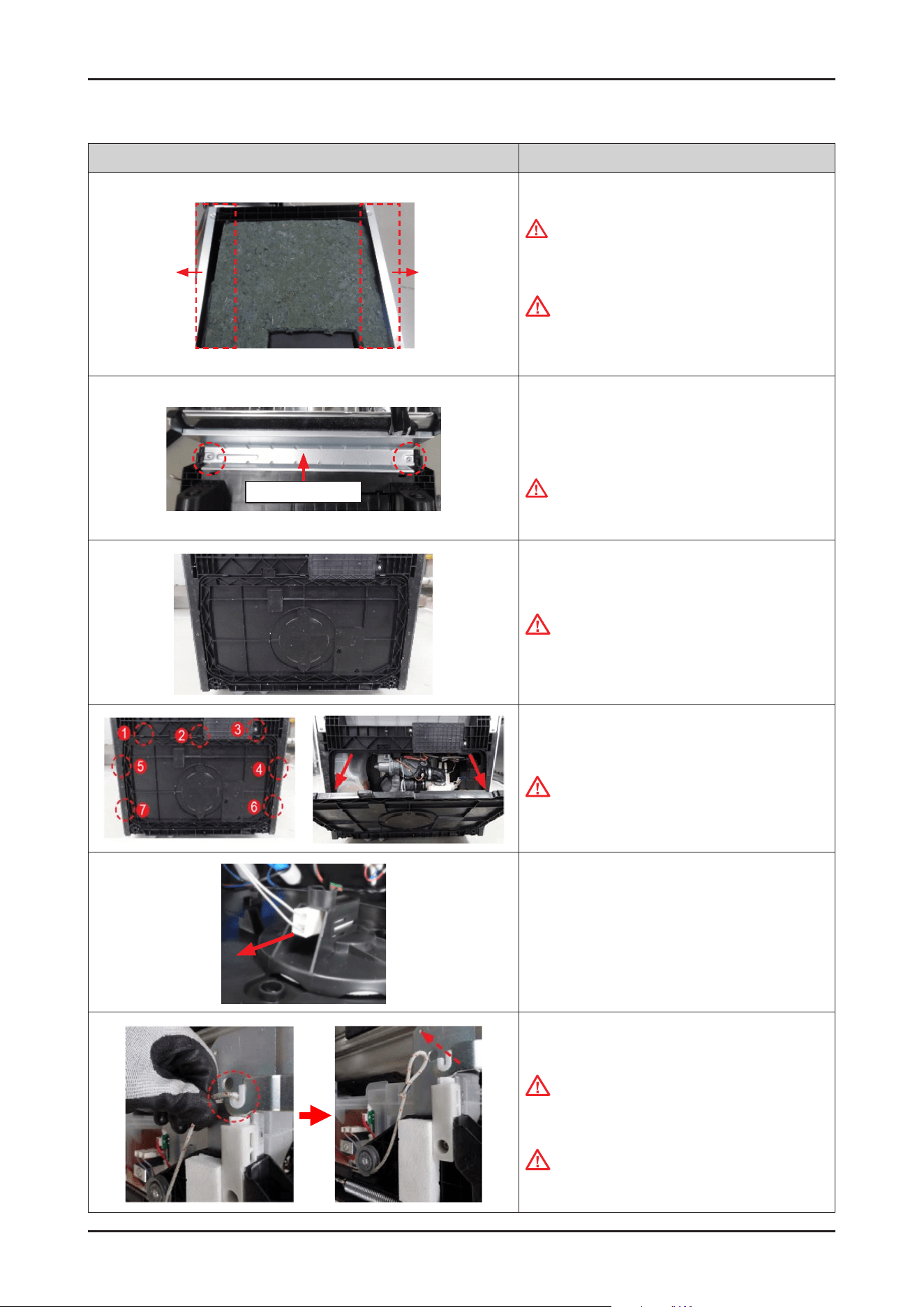
8. Lay down the dishwasher on its back.
CAUTION
Make sure to lay down the dishwasher carefully. If it
falls carelessly, It may cause damage.
9. Open the COVER BASE which is closed by 7 hooks
with a at-head screwdriver.
CAUTION
Make sure to release hooks carefully.
It can be brake easily if it’s opened carelessly.
10. Remove the leakage sensor from the COVER BASE.
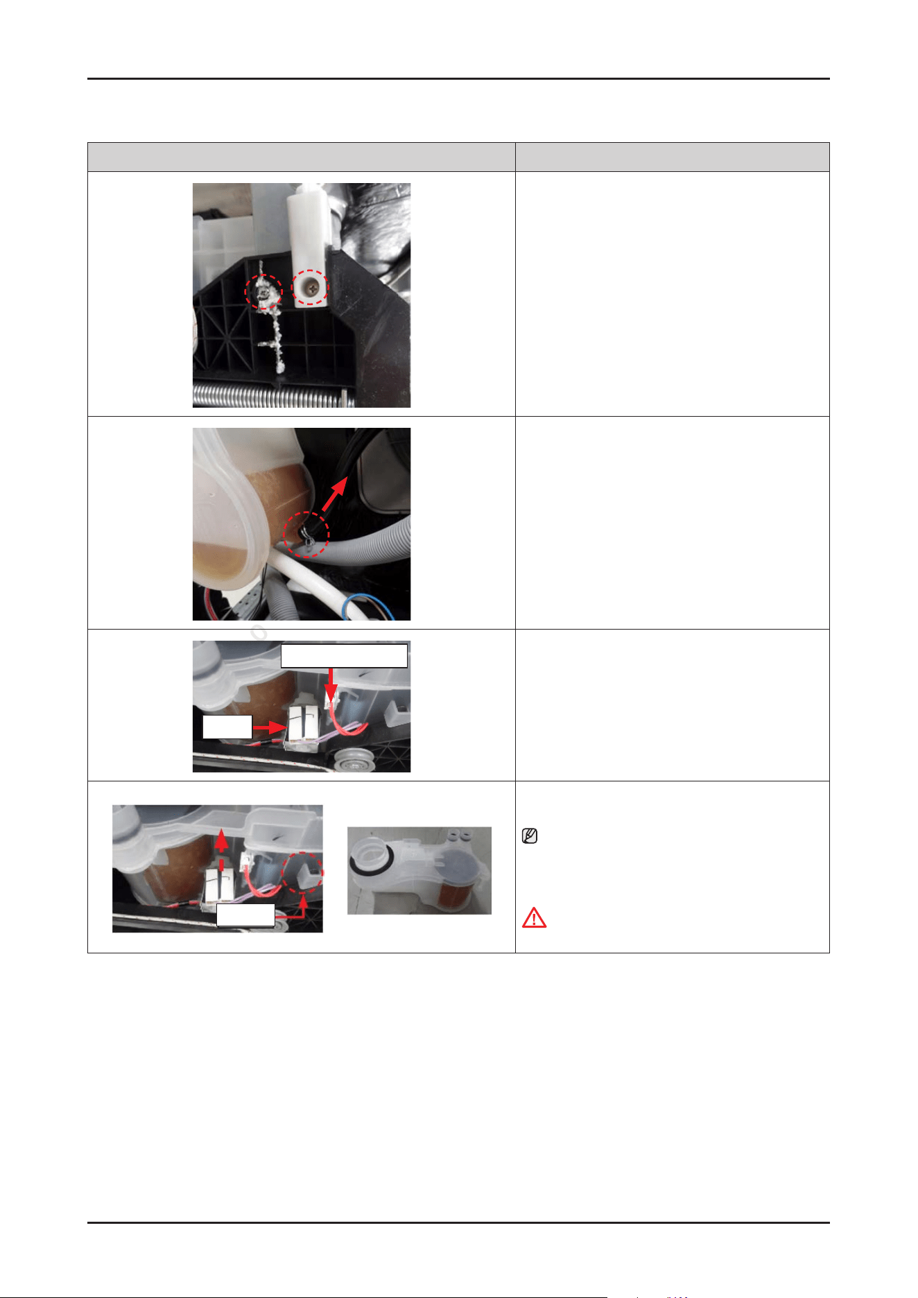
11. Remove HOLDER ROPE DOOR from the DOOR
HINGE left & right with the DOOR closed.
CAUTION
Pay attention to DOOR drop after removing the rope.
It may cause injury.
CAUTION
While dealing with Holder, please be aware that the
Spring and its being under tension can cause injury.
Disassembly and Reassembly _ 43
SAMSUNG PROPRIETARY. DO NOT COPY OR DISTRIBUTE WITHOUT PERMISSION
SAMSUNG PROPRIETARY. DO NOT COPY OR DISTRIBUTE WITHOUT PERMISSION
Photo Description
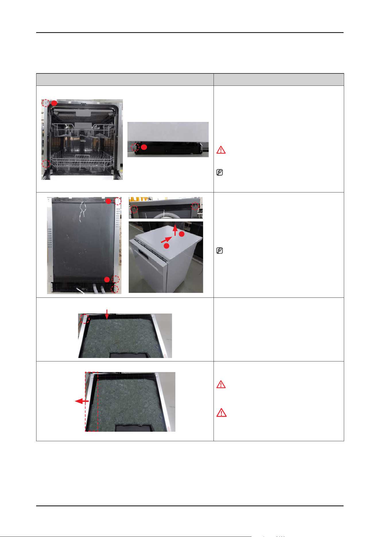
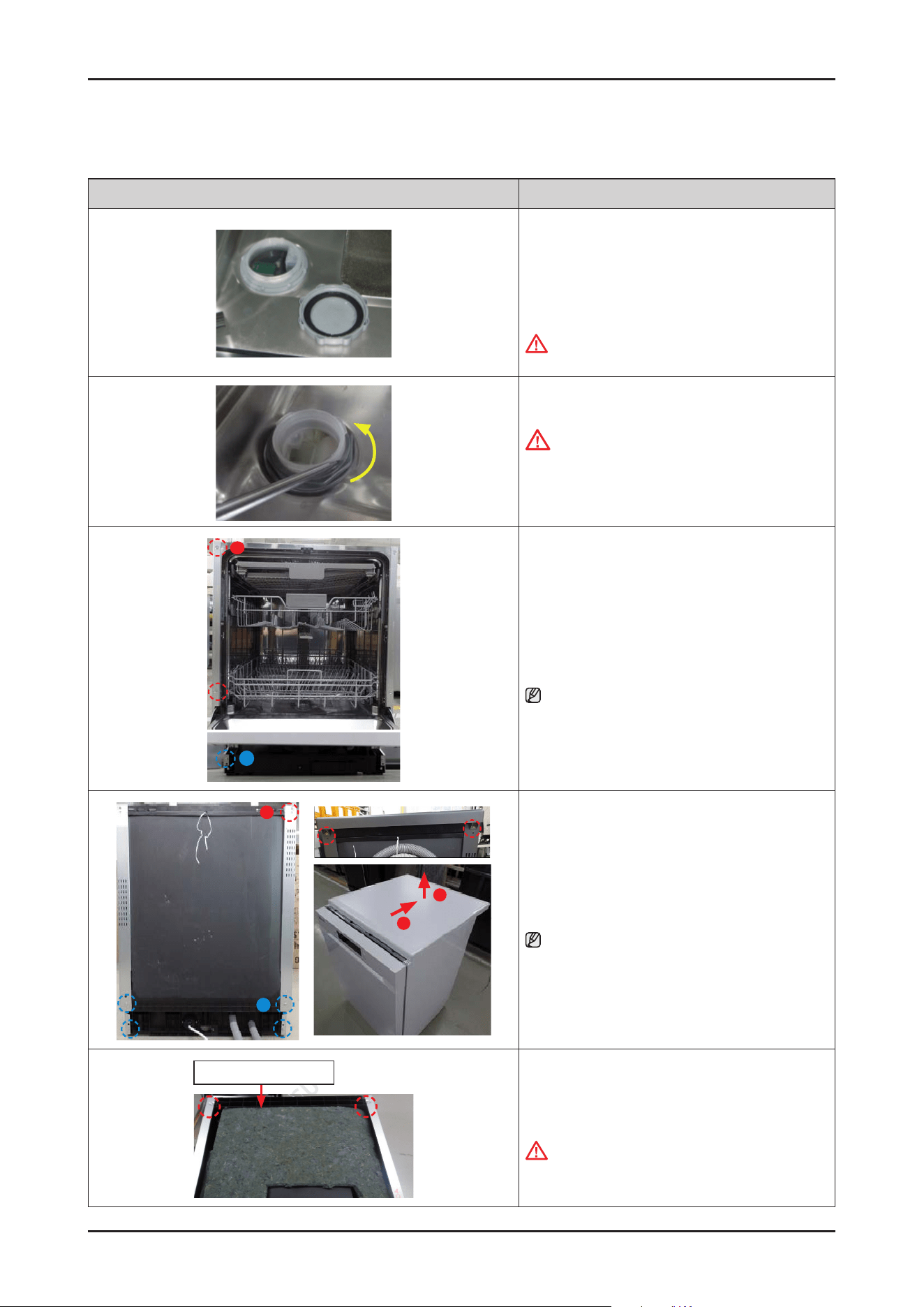
12. Remove EPS, and remove 2 screws at each side that
connected to tub with BASE.
(Total 4 screws at left/right side)
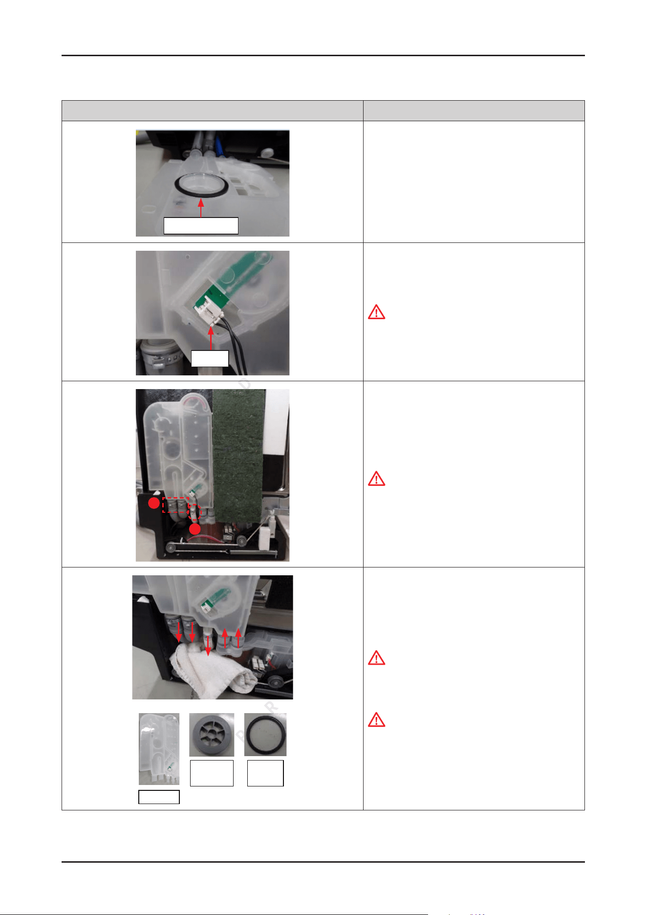
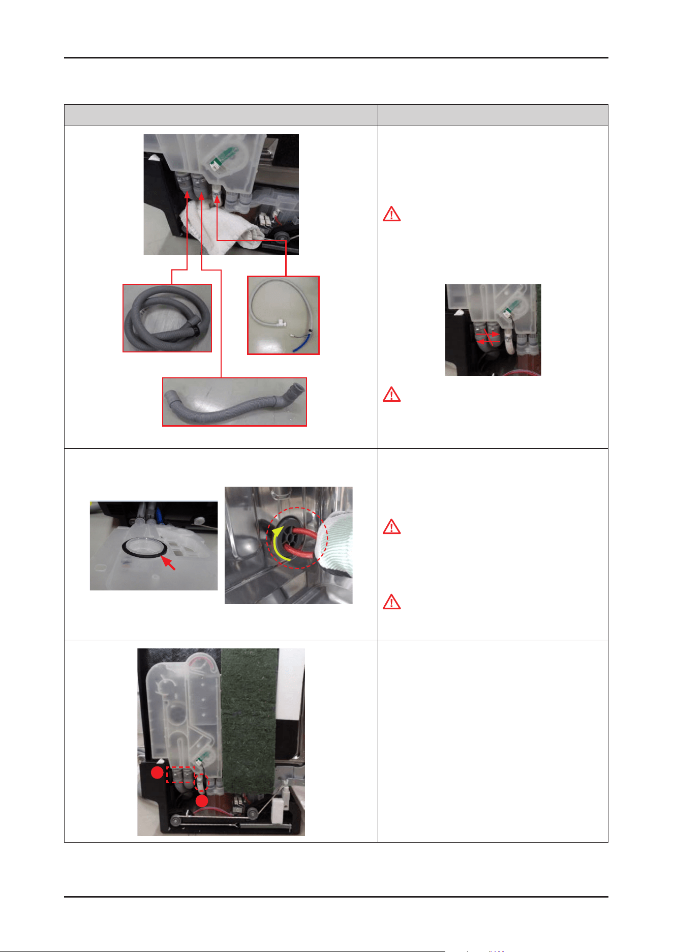
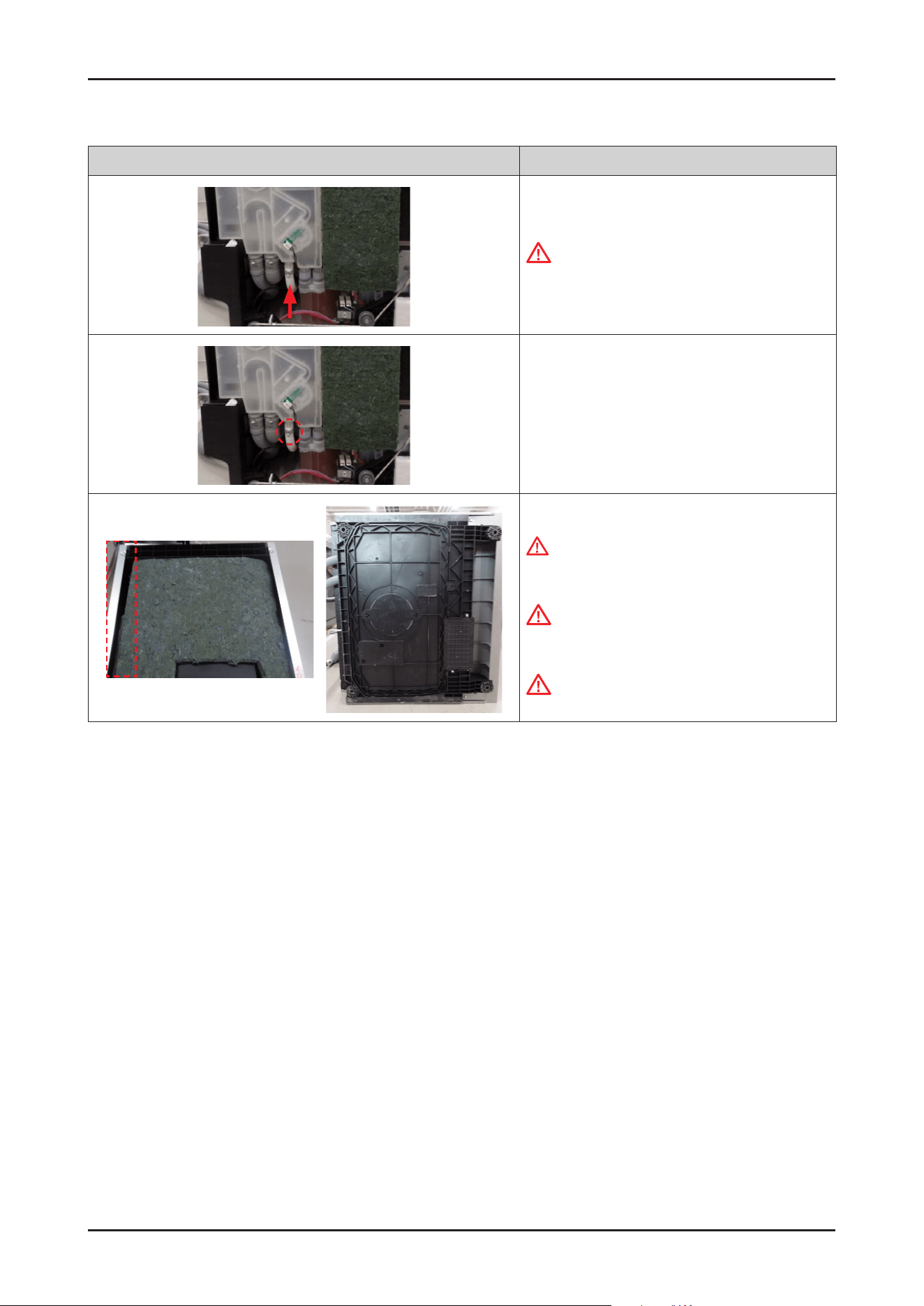
13. Remove the clamp and the hose connection with the
WATER SOFTENER.
Salt sensor wire
Valve
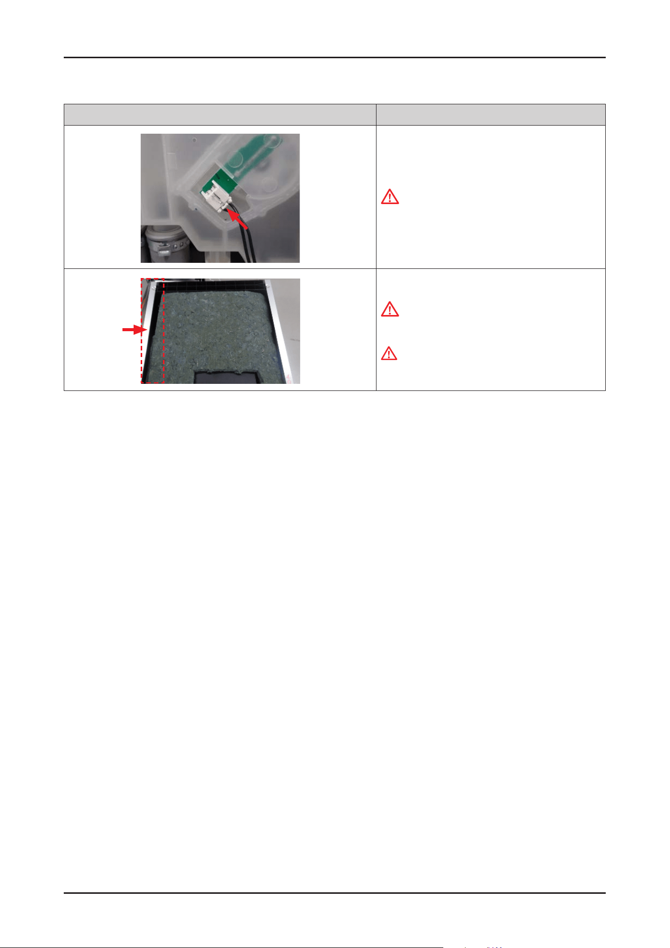
14.
Remove the connector terminals of salt sensor and
softener valve.
Holder
15. Pull out the WATER SOFTENER upward carefully.
NOTE :
Push the bottom of softener upward rst to release
holder from the BASE hook. And then pull out the
softener through bottom of BASE.
CAUTION
Be sure to check the seal of the WATER SOFTENER.
44 _ Disassembly and Reassembly
SAMSUNG PROPRIETARY. DO NOT COPY OR DISTRIBUTE WITHOUT PERMISSION
SAMSUNG PROPRIETARY. DO NOT COPY OR DISTRIBUTE WITHOUT PERMISSION
Photo Description
Holder
[ASSEMBLY]
1.
Place the WATER SOFTENER to BASE.
CAUTION
Pay attention to the location of holder.
Salt sensor wire
Valve
2. Connect the terminals of salt sensor and softener
valve.
CAUTION
Make sure the Wire harness is not getting stuck in
other parts.
3. Connect the hose from the SUMP to the WATER
SOFTENER, and t the clamp.
CAUTION
Make sure to insert the hoses correctly.
There's risks of leakage or poor performance when
it’s misassembled.
4. Fasten 2 screws at each side to assemble the tub to
BASE. (Total 4 screws at left/right side)
CAUTION
Do not over-tighten the screws that x plastic
parts, as this can cause damage (breaking the seat,
immediately or over the course of time.
5. Fit the HOLDER ROPE DOOR onto the both sides of
DOOR HINGE with the DOOR closed.
Disassembly and Reassembly _ 45
SAMSUNG PROPRIETARY. DO NOT COPY OR DISTRIBUTE WITHOUT PERMISSION
SAMSUNG PROPRIETARY. DO NOT COPY OR DISTRIBUTE WITHOUT PERMISSION
Photo Description
6. Connect the leakage sensor to the COVER BASE.
CAUTION
Make sure the Wire harness is not getting stuck in
other parts.
7. Assemble the COVER BASE.
CAUTION
Pay attention to the hooks not to broken.
8. Assemble the FRAME FRONT with 2 machine screws.
-
Machine Screws: DD81-02728A
WARNING
Do not do this work without safety gloves. It may
cause injury from sharp edges.
9. Assemble the SOFTENER HOLDER by rotating in a
clockwise direction.
10. Assemble the SOFTENER CAP by rotating in a
clockwise direction.
11. Assemble the SIDE PANEL left&right with the screws.
46 _ Disassembly and Reassembly
SAMSUNG PROPRIETARY. DO NOT COPY OR DISTRIBUTE WITHOUT PERMISSION
SAMSUNG PROPRIETARY. DO NOT COPY OR DISTRIBUTE WITHOUT PERMISSION
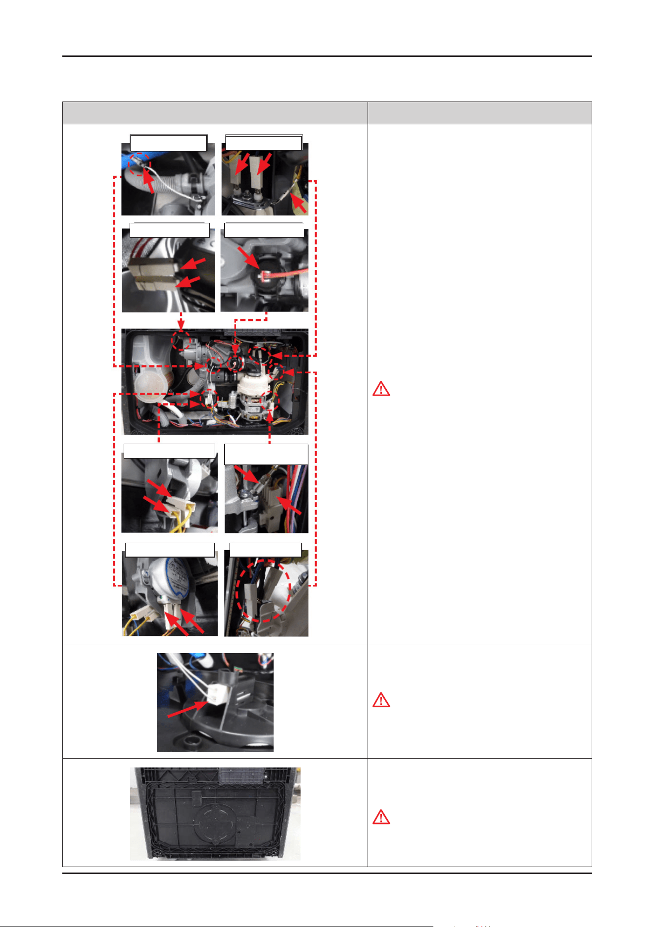
3-2-9. ASSY SUMP / SEAL SUMP
Photo Description
ASSY DUCT NOZZLE
HOLDER ROTOR LOWER
[DISASSEMBLY]
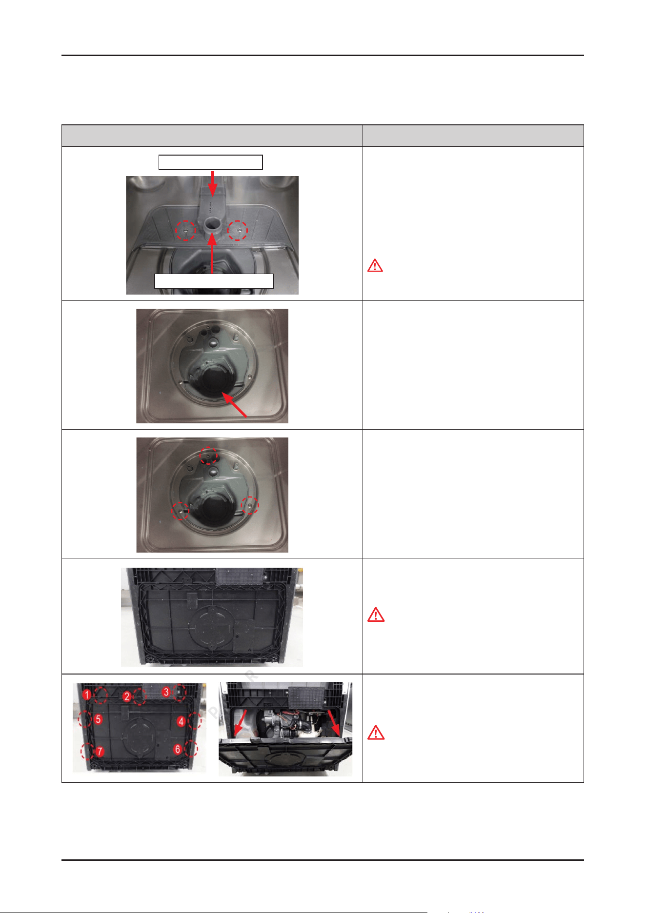
1. Remove two screws for xing ASSY DUCT NOZZLE,
and take it off and HOLDER ROTOR LOWER from the
SUMP.
-
Screws: DD81-02718A / 2 pcs
WARNING
Be sure to remove the power plug before servicing.
2. Remove remain water inside the SUMP using a rag.
3. Remove 3 screws for xing the SUMP to TUB.
- Screws: DD81-02718A / 3 pcs
4. Lay down the dishwasher on the back.
CAUTION
Make sure to lay down the dishwasher carefully.
If it falls carelessly, It may cause damage.
5. Open the COVER BASE which is closed by
7 hooks with at-head screwdriver.
CAUTION
Make sure to release hooks carefully.
It can brake easily if it’s opened carelessly.
Disassembly and Reassembly _ 47
SAMSUNG PROPRIETARY. DO NOT COPY OR DISTRIBUTE WITHOUT PERMISSION
SAMSUNG PROPRIETARY. DO NOT COPY OR DISTRIBUTE WITHOUT PERMISSION
Photo Description
6. Remove the leakage sensor from the COVER BASE.
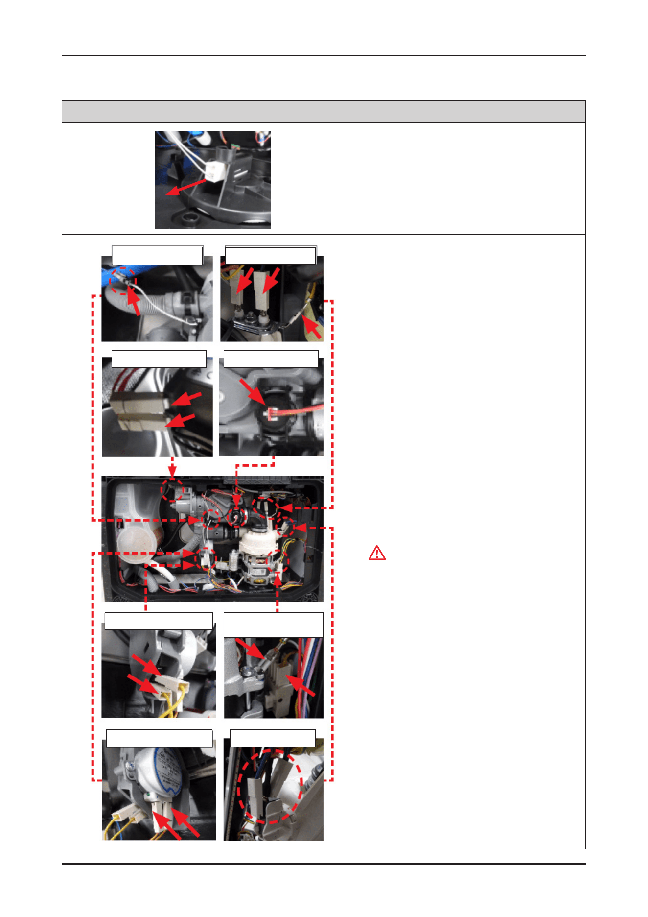
Thermistor
Drain Pump
Distribution Switch
Distribution Motor Micro Switch
Heater / Ground
Turbidity Sensor
Circulation Pump/
Ground
7. Remove the terminals of electric parts that
connected to SUMP.
CAUTION
Don’t bent or be taken from the wire While removing
the terminals.
48 _ Disassembly and Reassembly
SAMSUNG PROPRIETARY. DO NOT COPY OR DISTRIBUTE WITHOUT PERMISSION
SAMSUNG PROPRIETARY. DO NOT COPY OR DISTRIBUTE WITHOUT PERMISSION
Photo Description
8. Remove the rubber from the pump assembly.
(4 points).
Hose Drain In
Pressure Hose
Inlet Hose
9. Remove the clamps that connected with the hoses
to SUMP.
-
Clamp for HOSE DRAIN IN
-
Clamp for HOSE PRESSURE SWITCH
-
Clamp for INLET HOSE
ASSY SUMP
SEAL SUMP
10. Remove the SUMP assembly by pushing down.
[ASSEMBLY]
1. Place the SUMP under the TUB to t the bosses of
SUMP to holes of TUB.
Disassembly and Reassembly _ 49
SAMSUNG PROPRIETARY. DO NOT COPY OR DISTRIBUTE WITHOUT PERMISSION
SAMSUNG PROPRIETARY. DO NOT COPY OR DISTRIBUTE WITHOUT PERMISSION
Photo Description
2. Fasten 3 screws to x the SUMP to TUB.
-
Screws: DD81-02718A / 3 pcs
Hose Drain In
Pressure Hose
Inlet Hose
3. Connected the hoses to SUMP and fasten clamps.
-
Clamp for HOSE DRAIN IN
-
Clamp for HOSE PRESSURE SWITCH
-
Clamp for PVC HOSE
CAUTION
Make sure to insert the hoses correctly. There's
risks of leakage or poor performance when it’s
misassembled.
Tips for removing and reassembling hoses from the
outlet : the force should be applied aligned with the
outlet direction, with small rotation of the hose.
(not bending to sides or twisting)
4. Assemble the MOTOR PUMP with the DAMPER
PUMP.
50 _ Disassembly and Reassembly
SAMSUNG PROPRIETARY. DO NOT COPY OR DISTRIBUTE WITHOUT PERMISSION
SAMSUNG PROPRIETARY. DO NOT COPY OR DISTRIBUTE WITHOUT PERMISSION
Photo Description
Thermistor
Drain Pump
Distribution Switch
Distribution Motor Micro Switch
Heater / Ground
Turbidity Sensor
Circulation Pump/
Ground
5. Connect the terminals of electric parts that are
connected to SUMP.
CAUTION
Make sure the Wire harness is not getting stuck in
other parts.
6. Connect the leakage sensor to the COVER BASE.
CAUTION
Make sure the Wire harness is not getting stuck in
other parts.
7. Assemble the COVER BASE.
CAUTION
Pay attention to the hooks not to broken.
Disassembly and Reassembly _ 51
SAMSUNG PROPRIETARY. DO NOT COPY OR DISTRIBUTE WITHOUT PERMISSION
SAMSUNG PROPRIETARY. DO NOT COPY OR DISTRIBUTE WITHOUT PERMISSION
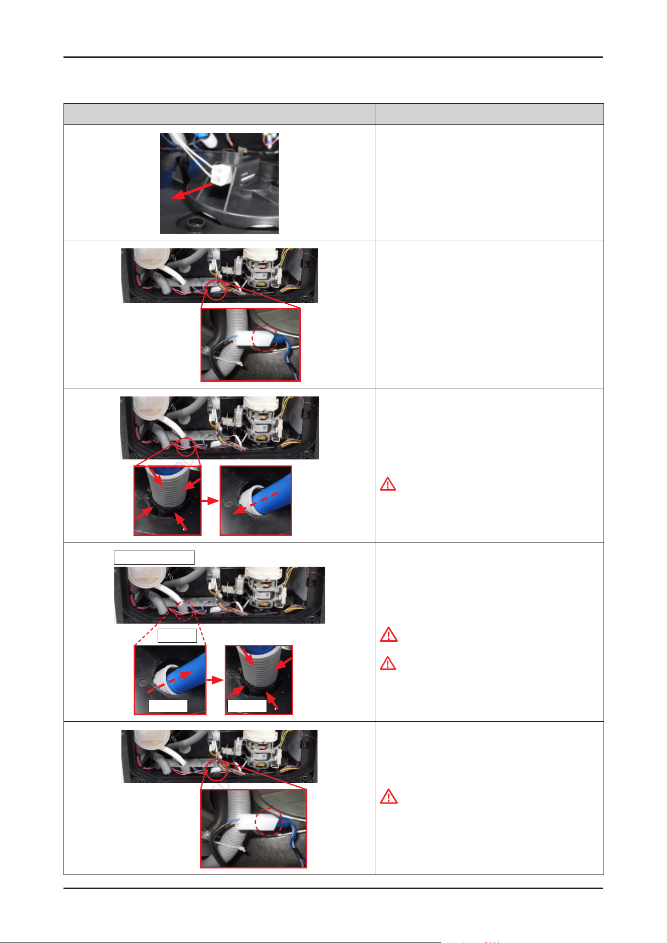
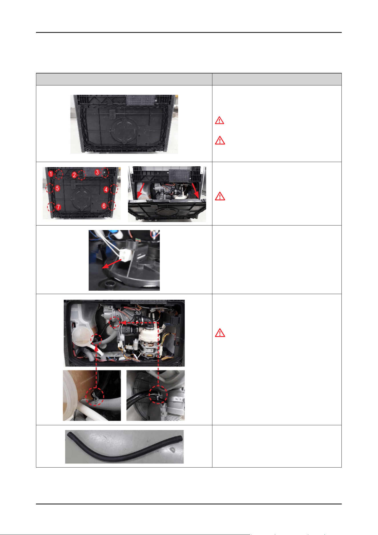
3-2-10. HOSE SUMP IN
Photo Description
[DISASSEMBLY]
1. Lay down the dishwasher on its back side.
WARNING
Be sure to remove the power plug before servicing.
.
CAUTION
Make sure to lay down the dishwasher carefully.
If it falls carelessly, It may cause damage.
2. Open the COVER BASE which is closed by 7 hooks
with at-head screwdriver.
CAUTION
Make sure to release hooks carefully.
It can be brake easily if it’s opened carelessly
3. Remove the leakage sensor from the COVER BASE.
4. Remove 2 clamps.
CAUTION
It may spill the water from the SUMP and WATER
SOFTENER.
Place some towels or rags under the disassembled
parts.
TIP!
For a small amount of water, pet absorbent
pads can be helpful as well.
5. Remove HOSE SUMP IN.
52 _ Disassembly and Reassembly
SAMSUNG PROPRIETARY. DO NOT COPY OR DISTRIBUTE WITHOUT PERMISSION
SAMSUNG PROPRIETARY. DO NOT COPY OR DISTRIBUTE WITHOUT PERMISSION
Photo Description
[ASSEMBLY]
1. Assemble the hose with 2 clamps.
2. Connect the leakage sensor to the COVER BASE.
CAUTION
Make sure the Wire harness is not getting stuck in
other parts.
3. Assemble the COVER BASE.
CAUTION
Pay attention to the hooks not to broken.

Disassembly and Reassembly _ 53
SAMSUNG PROPRIETARY. DO NOT COPY OR DISTRIBUTE WITHOUT PERMISSION
SAMSUNG PROPRIETARY. DO NOT COPY OR DISTRIBUTE WITHOUT PERMISSION
3-2-11. DOOR SWITCH
Photo Description
[DISASSEMBLY]
1. Remove the protecting lm of the DOOR switch, and
remove the 3 terminals of wire harness.
WARNING
Be sure to remove the power plug before servicing.
NOTE :
In case of Free standing models, remove the top cover
rst.
2. Open the dishwasher’s DOOR, and remove the 2
screws to remove the DOOR SWITCH from the TUB.
-
Screws: DD81-02693A / 2 pcs
3. Remove the DOOR SWITCH.
[ASSEMBLY]
1. Fasten 2 screws to x the DOOR SWITCH to TUB, and
connect the terminals of DOOR SWITCH.
CAUTION
Make sure the Wire harness is not getting stuck in
other parts.
54 _ Disassembly and Reassembly
SAMSUNG PROPRIETARY. DO NOT COPY OR DISTRIBUTE WITHOUT PERMISSION
SAMSUNG PROPRIETARY. DO NOT COPY OR DISTRIBUTE WITHOUT PERMISSION
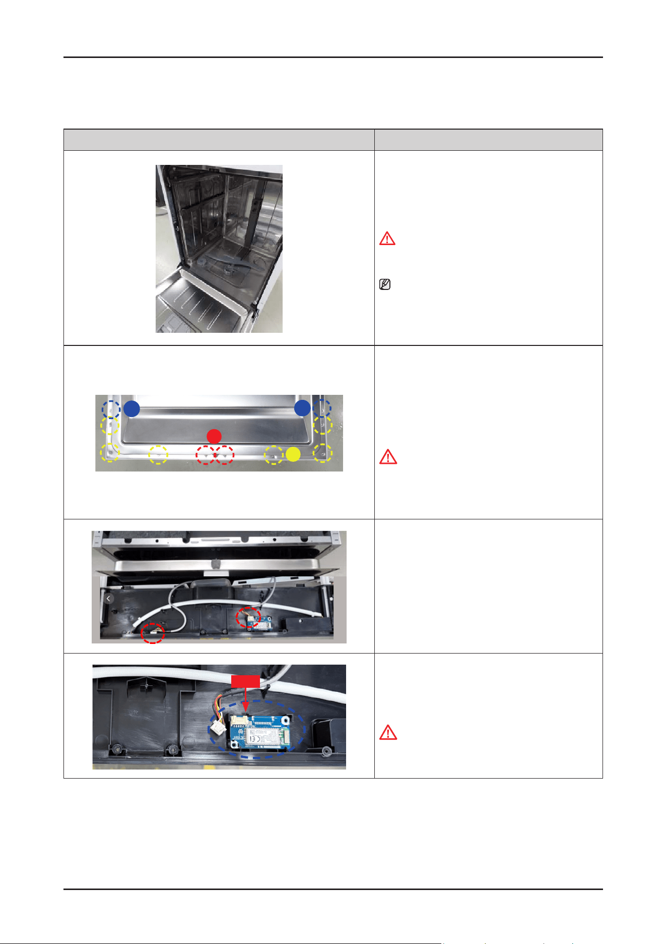
3-2-12. ASSY-PANEL CONTROL / WI-FI PBA (DW70****F*/DW70****S*/DW70****U*)
Photo Description
[DISASSEMBLY]
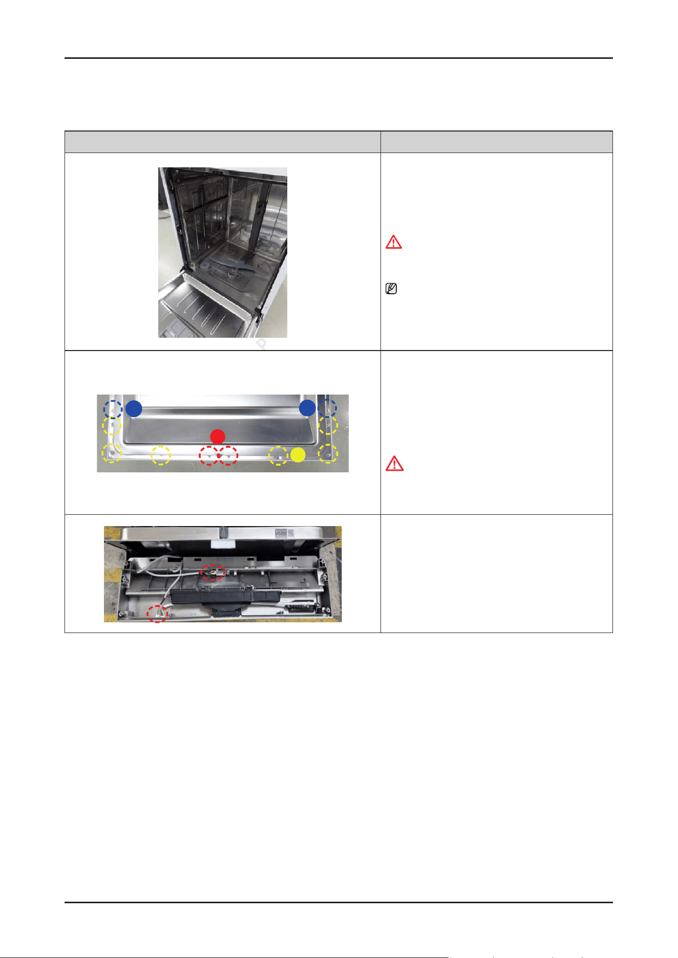
1. Open the dishwasher’s DOOR.
WARNING
Be sure to remove the power plug before servicing.
NOTE :
It is not necessary to uninstall the dishwasher from
the furniture cabinet.
B
A
C
C
2. Remove 10 screws to take off the ASSY CONTROL
PANEL with Torx® T15 screwdriver.
-
Type A: DD81-02756A / 2 pcs
-
Type B: DD81-02758A / 6 pcs
-
Type C: DD81-02757A / 2 pcs
CAUTION
The screws can fall into the SUMP after disassembly.
Keep the screws away in a safe place to reassemble
the DOOR.
3. Remove wire connectors of the SUB PBA &
Wi-Fi PBA .
Disassembly and Reassembly _ 55
SAMSUNG PROPRIETARY. DO NOT COPY OR DISTRIBUTE WITHOUT PERMISSION
SAMSUNG PROPRIETARY. DO NOT COPY OR DISTRIBUTE WITHOUT PERMISSION
Photo Description
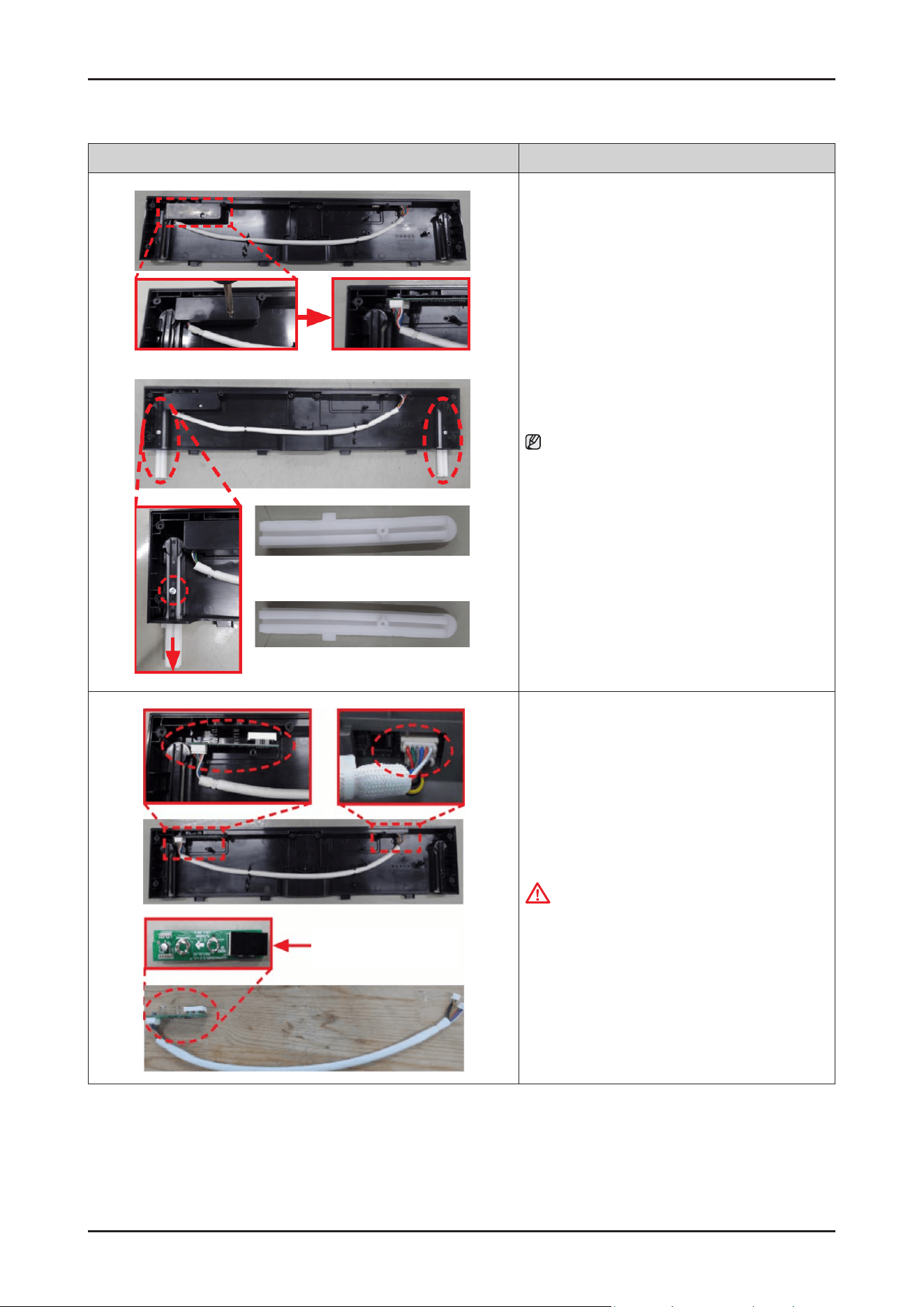
hook
hook
4. Remove the COVER HANDLE from the CONTROL
PANEL assembly.
CAUTION
Be careful to remove the COVER HANDLE from the
hooks.
hook
5. Remove the Wi-Fi PBA from the CONTROL PANEL
assembly.
CAUTION
Be careful to remove the Wi-Fi PBA from the hook.
6. Replace ASSY-PANEL CONTROL SUB &
Wi-Fi PBA.
CAUTION
Don’t touch Wi module with wet hands or metallic
objects.
56 _ Disassembly and Reassembly
SAMSUNG PROPRIETARY. DO NOT COPY OR DISTRIBUTE WITHOUT PERMISSION
SAMSUNG PROPRIETARY. DO NOT COPY OR DISTRIBUTE WITHOUT PERMISSION
Photo Description
[ASSEMBLY]
1. Assemble the COVER HANDLE to the ASSY-PANEL
CONTROL SUB.
Put the COVER HANDLE into the 4 hooks at the same
time carefully.
hook
2. Assemble the WiFi PBA to the ASSY-PANEL
CONTROL SUB.
Put the WiFi PBA into the lower position rst, and put
it to lock the upper hook.
CAUTION
Be careful to insert the Cover handle to the hooks.
3. Connect the wire harness of the SUB PBA &
Wi-Fi PBA.
CAUTION
Make sure the Wire harness is not getting stuck in
other parts.
4. Assemble the ASSY CONTROL PANEL to DOOR
OUTER.
CAUTION
Be careful to t the ribs under the ASSY CONTROL
PANEL to the holes of DOOR OUTER.
B
A
C
C
5. Fix 10 screws to assemble the ASSY CONTROL PANEL
with Torx® T15 screwdriver.
- Type A: DD81-02756A / 2 pcs
- Type B: DD81-02758A / 6 pcs
- Type C: DD81-02757A / 2 pcs
Disassembly and Reassembly _ 57
SAMSUNG PROPRIETARY. DO NOT COPY OR DISTRIBUTE WITHOUT PERMISSION
SAMSUNG PROPRIETARY. DO NOT COPY OR DISTRIBUTE WITHOUT PERMISSION
3-2-13. ASSY-PANEL CONTROL / WI-FI PBA (DW70****B*/ DW70****I*)
Photo Description
[DISASSEMBLY]
1. Open the dishwasher’s DOOR.
WARNING
Be sure to remove the power plug before servicing.
NOTE :
It is not necessary to uninstall the dishwasher from
the furniture cabinet.
B
A
C
C
2. Remove 10 screws to take off the ASSY CONTROL
PANEL with Torx® T15 screwdriver.
-
Type A: DD81-02756A / 2 pcs
-
Type B: DD81-02758A / 6 pcs
-
Type C: DD81-02757A / 2 pcs
CAUTION
The screws can fall into the SUMP after
disassembly.
Keep the screws away in a safe place to reassemble
the DOOR.
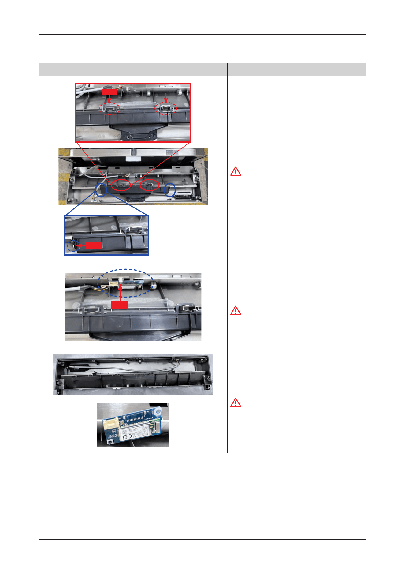
3. Remove wire connectors of the SUB PBA &
Wi-Fi PBA .
hook
4. Remove the Wi-Fi PBA from the CONTROL PANEL
assembly.
CAUTION
Be careful to remove the Wi-Fi PBA from the hook.
58 _ Disassembly and Reassembly
SAMSUNG PROPRIETARY. DO NOT COPY OR DISTRIBUTE WITHOUT PERMISSION
SAMSUNG PROPRIETARY. DO NOT COPY OR DISTRIBUTE WITHOUT PERMISSION
Photo Description
GUIDE SLIDING R
GUIDE SLIDING L
5. Remove a screw to remove the COVER DISPLAY
PBA.
-
COVER DISPLAY PBA : DD81-02484A
-
Screw : DD81-02695A
NOTE :
In case of Sliding Hinge models(DW70****I*),
they have additional parts (GUIDE SLIDING L, R).
Release screws to remove them.
- Screws : DD81-02694A
- GUIDE SLIDING L, R : DD81-02970A
DD81-02971A
DISPLAY PBA
6. Remove the DISPLAY PBA from the ASSY CONTROL
PANEL.
CAUTION
Be careful to release the DISPLAY PBA from the
hook.
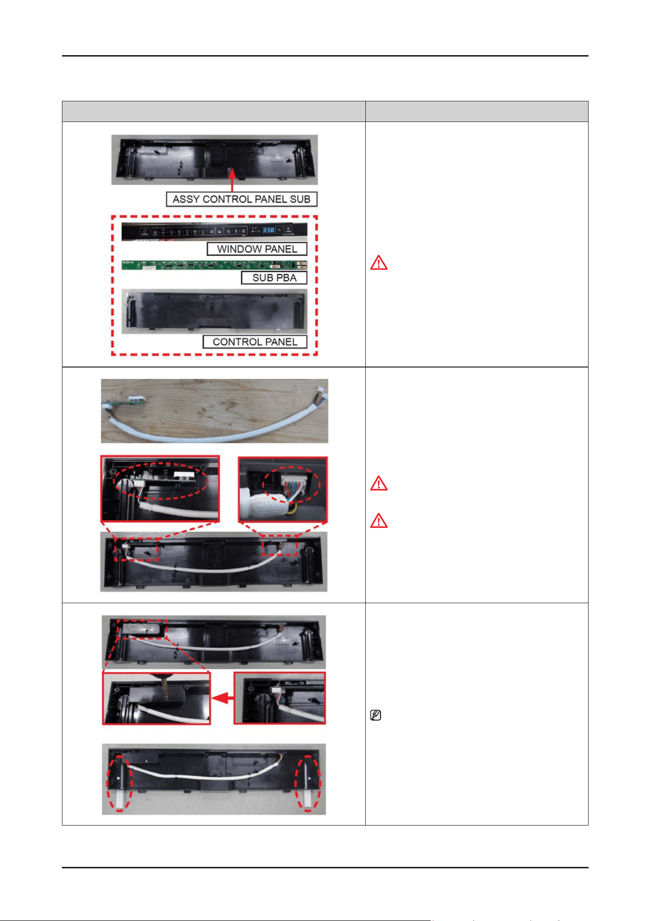
Disassembly and Reassembly _ 59
SAMSUNG PROPRIETARY. DO NOT COPY OR DISTRIBUTE WITHOUT PERMISSION
SAMSUNG PROPRIETARY. DO NOT COPY OR DISTRIBUTE WITHOUT PERMISSION
Photo Description
7. SUB PBA and CONTROL PANEL will be serviced
together by ASSY CONTROL PANEL SUB.
CAUTION
Don’t touch Display PBA with wet hands
or metallic objects.
[ASSEMBLY]
1. Assemble the DISPLAY PBA and wire harness to
CONTROL PANEL
CAUTION
Pay attention to assemble DISPLAY PBA with hooks.
CAUTION
Make sure the Wire harness is not getting stuck in
other parts.
2. Fasten a screw to x COVER DISPLAY PBA.
NOTE :
In case of Sliding Hinge models(DW70*****I*),
x screws to assemble GUIDE SLIDING L, R.
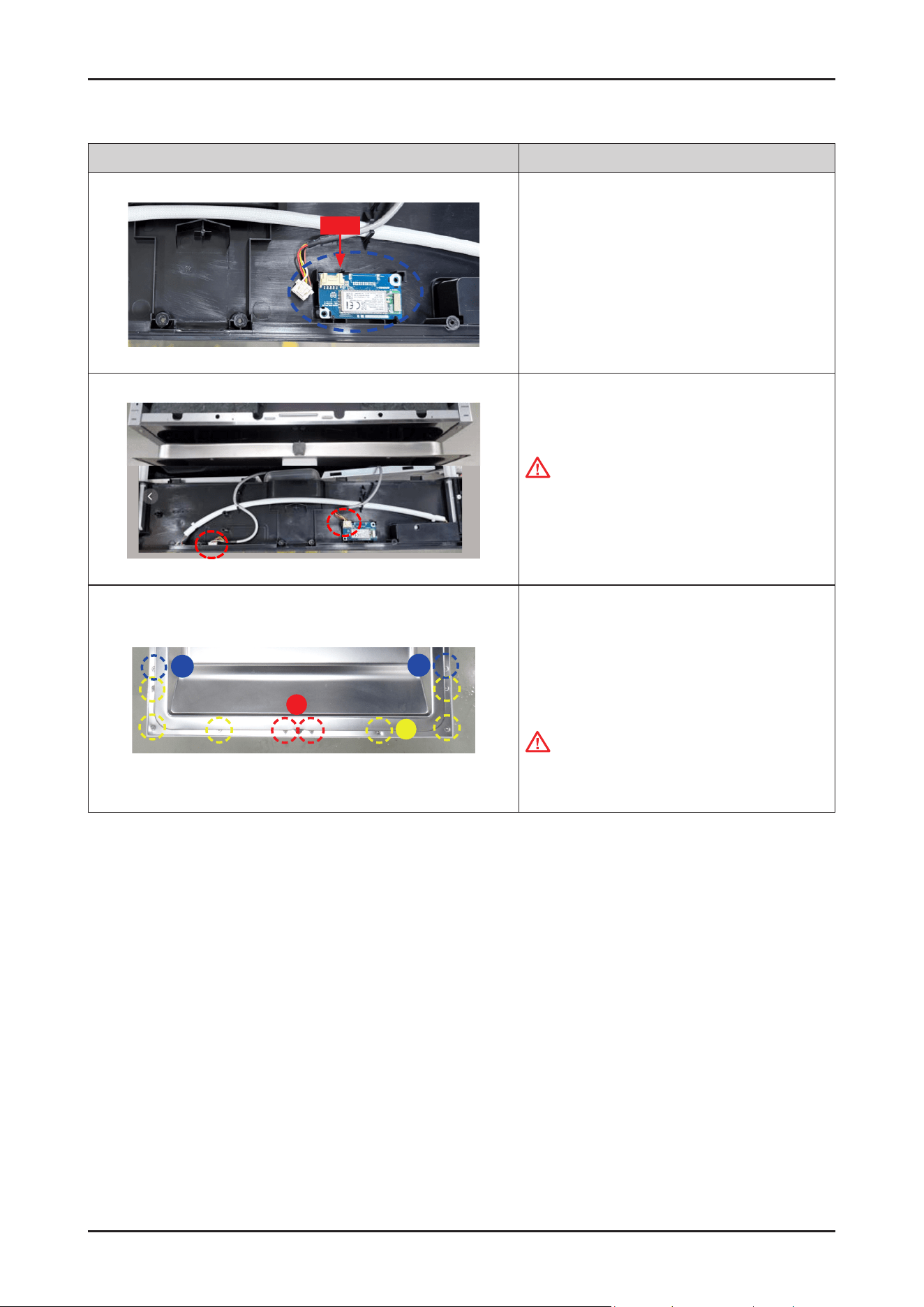
60 _ Disassembly and Reassembly
SAMSUNG PROPRIETARY. DO NOT COPY OR DISTRIBUTE WITHOUT PERMISSION
SAMSUNG PROPRIETARY. DO NOT COPY OR DISTRIBUTE WITHOUT PERMISSION
Photo Description
hook
3. Assemble the WiFiPBA to the ASSY-PANEL
CONTROL SUB.
Put the WiFiPBA into the upper position rst, and
put it to lock the lower hook.
4.
Connect the wire harness of the SUB PBA & Wi-Fi
PBA
CAUTION
Make sure the Wire harness is not getting stuck in
other parts.
B
A
C
C
5.
Fix 10 screws to assemble the ASSY CONTROL
PANEL with Torx® T15 screwdriver.
-
Type A: DD81-02756A / 2 pcs
-
Type B: DD81-02758A / 6 pcs
-
Type C: DD81-02757A / 2 pcs
CAUTION
Be careful not to mix metal and plastic screws for
reassembly.
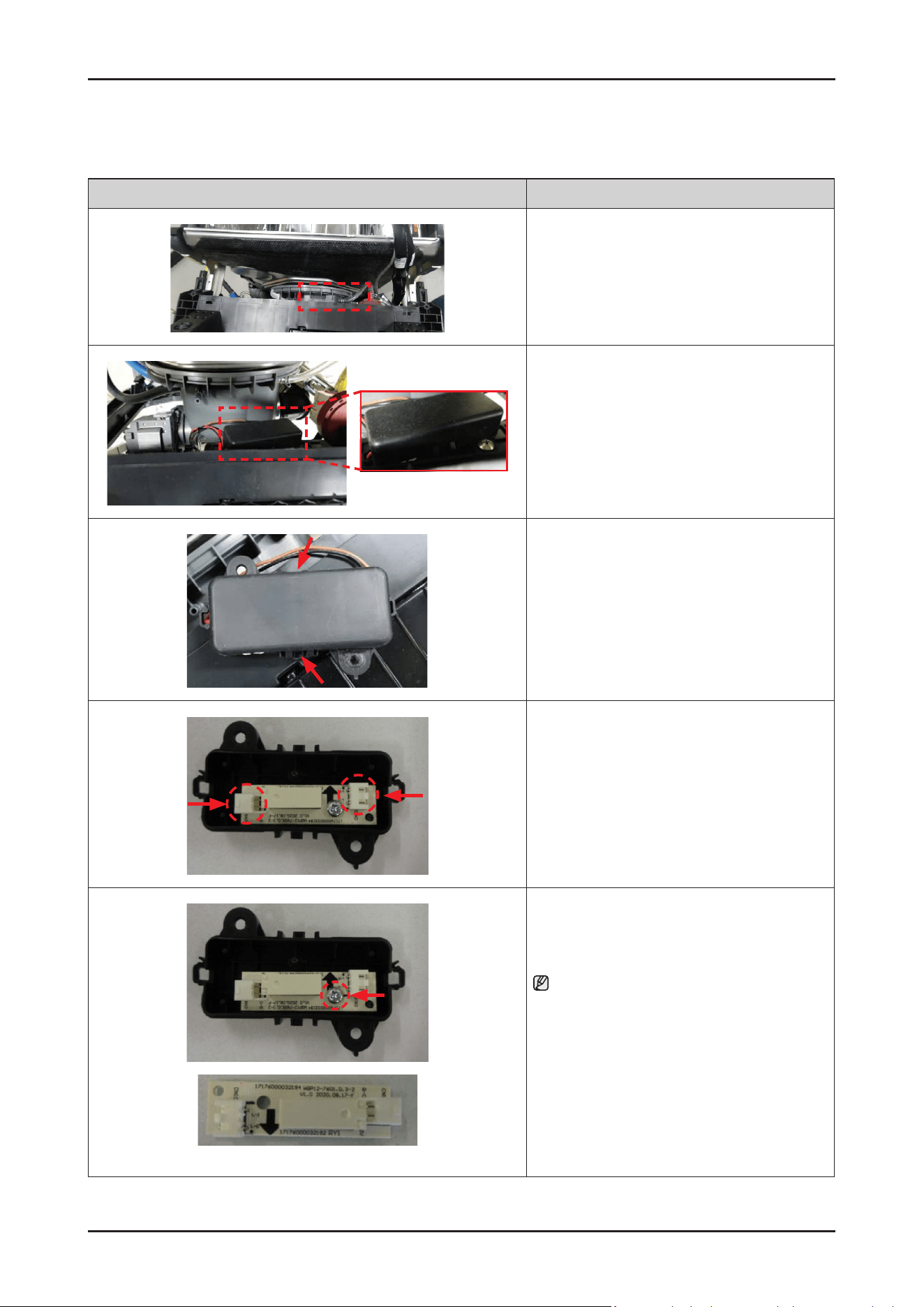
Disassembly and Reassembly _ 61
SAMSUNG PROPRIETARY. DO NOT COPY OR DISTRIBUTE WITHOUT PERMISSION
SAMSUNG PROPRIETARY. DO NOT COPY OR DISTRIBUTE WITHOUT PERMISSION
3-2-14. AUTO DOOR PBA
Photo Description
[DISASSEMBLY]
※ PREPARATION: Disassemble the FRAME FRONT.
1. Remove the screw xing the COVER of
the AUTO DOOR PBA.
2. Release the 2 hooks of the COVER of
the AUTO DOOR PBA.
3. Remove the 2 wire connectors.
Auto door PBA
4. Remove the screw xing the AUTO DOOR PBA.
NOTE :
AUTO DOOR PBA will be serviced by assembly
(DD82-01948A).
[ASSEMBLY]
※ Reassembly is the reverse order of disassembly.
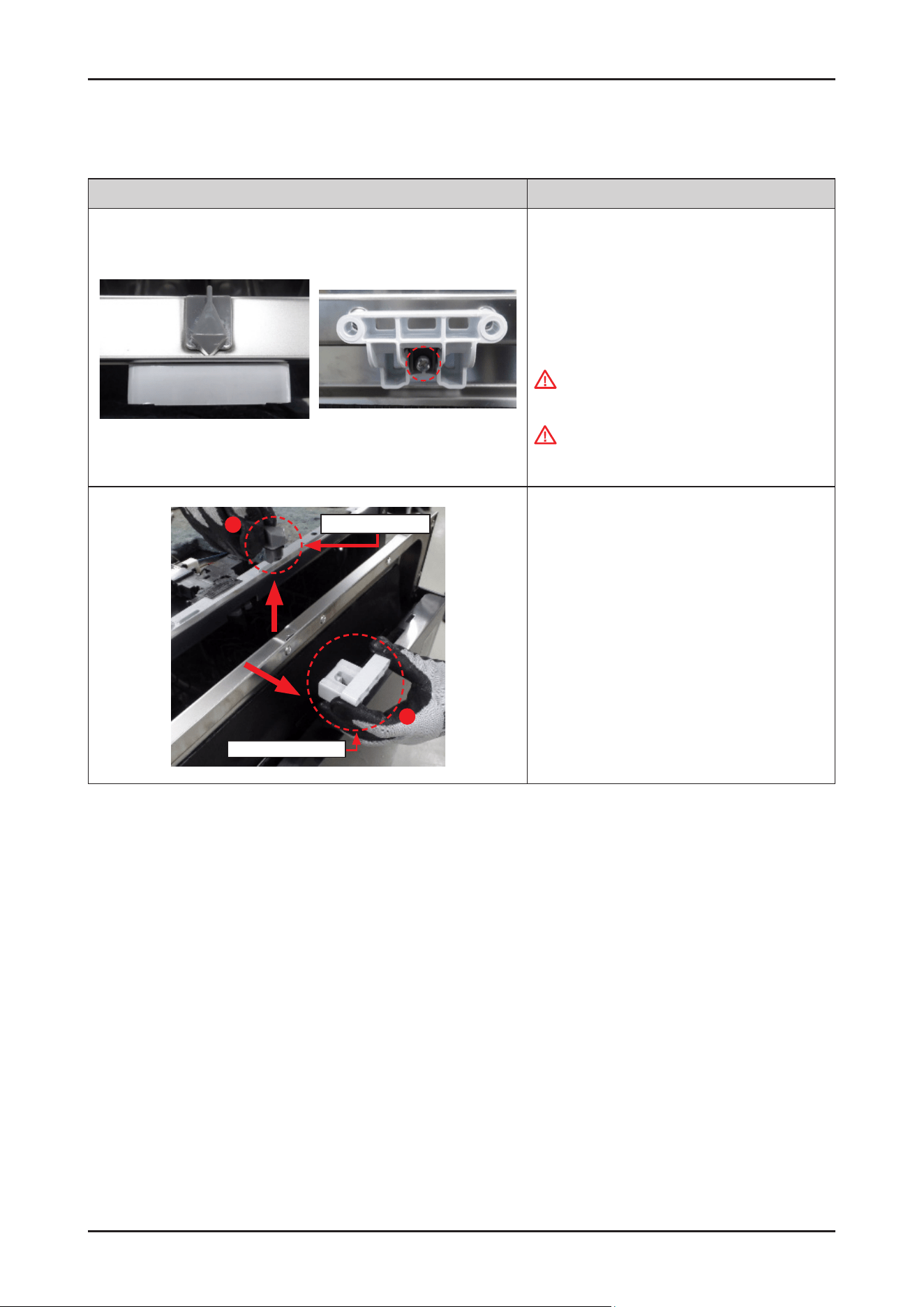
62 _ Disassembly and Reassembly
SAMSUNG PROPRIETARY. DO NOT COPY OR DISTRIBUTE WITHOUT PERMISSION
SAMSUNG PROPRIETARY. DO NOT COPY OR DISTRIBUTE WITHOUT PERMISSION
3-2-15. DOOR LOCK HOOK
Photo Description
[DISASSEMBLY]
※ PREPARATION: Disassemble the CONTROL PANEL.
1.
Remove 1 screw xing the DOOR LOCK HOOK.
-
Screw: DD81-02964A / 1 pc
WARNING
Be sure to remove the power plug before servicing.
WARNING
Do not do this work without safety gloves.
It may cause injury from sharp edges.
1
2
DOOR LOCK HOOK
HOLDER DOOR LOCK
2. Remove the DOOR LOCK HOOK and the HOLDER
DOOR LOCK from the inner DOOR.
[ASSEMBLY]
※Reassembly is the reverse order of disassembly.
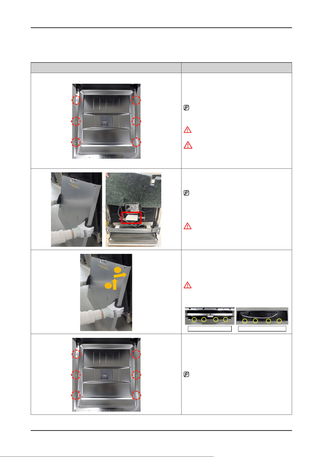
Disassembly and Reassembly _ 63
SAMSUNG PROPRIETARY. DO NOT COPY OR DISTRIBUTE WITHOUT PERMISSION
SAMSUNG PROPRIETARY. DO NOT COPY OR DISTRIBUTE WITHOUT PERMISSION
3-2-16. DOOR OUTER
Photo Description
[DISASSEMBLY]
1. Open the dishwasher’s DOOR, and remove the
6 screws to take off DOOR OUTER.
NOTE :
Use the Torx® T15 screw driver.
-
Screws : DD81-02/757A / 6 pcs
WARNING
Be sure to remove the power plug before servicing.
CAUTION
The screws can fall into the SUMP after
disassembly. Keep the screws away in a safe place
to reassemble the DOOR.
.
2. Remove the DOOR OUTER.
NOTE :
When remove the outer door, please do not remove
the white cotton marked with the red box on the inner
door. Please keep the white cotton in its adhesive
position.
WARNING
Do not do this work without safety gloves.
It may cause injury from sharp edges.
1
2
[ASSEMBLY]
1.
Assemble the holes of the DOOR OUTER to hooks of
the CONTROL PANEL.
WARNING
Do not do this work without safety gloves.
It may cause injury from sharp edges
Holes of DOOR OUTER Hooks of CONTROL PANEL
2. Fasten the 6 screws to x the DOOR OUTER.
NOTE :
Use the Torx® T15 screw driver.
-
Screws : DD81-02/757A / 6 pcs
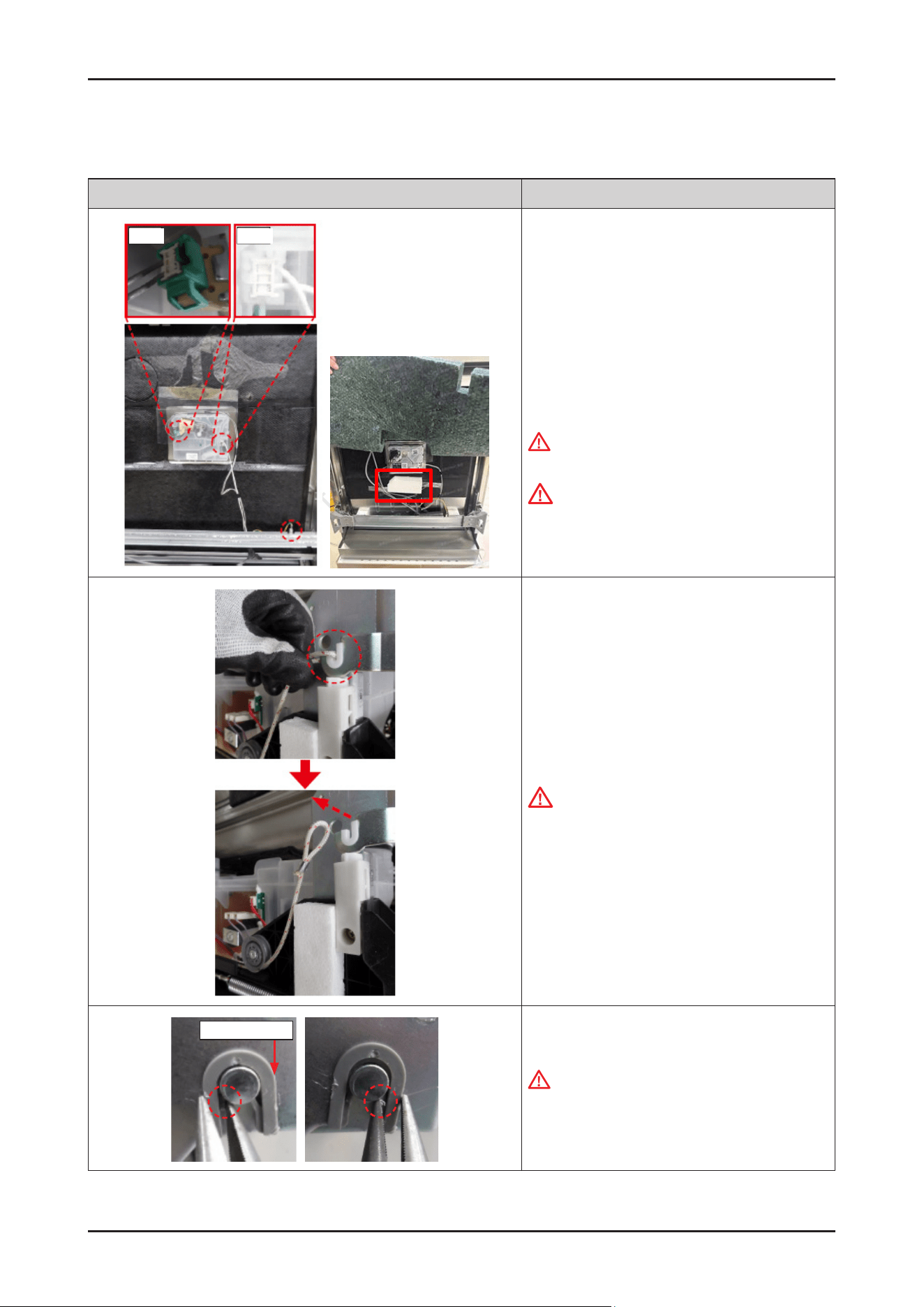
64 _ Disassembly and Reassembly
SAMSUNG PROPRIETARY. DO NOT COPY OR DISTRIBUTE WITHOUT PERMISSION
SAMSUNG PROPRIETARY. DO NOT COPY OR DISTRIBUTE WITHOUT PERMISSION
3-2-17. DOOR INNER / DOOR HINGE (EXCEPT DW70*****I*)
Photo Description
Hook Hook
[DISASSEMBLY]
※ PREPARATION: Disassemble the DOOR OUTER,
CONTROL PANEL and
SIDE PANEL left & right.
1.
Remove 2 terminals that connected to DETERGENT
DISPENSER, and 1 ground wire that connected to
BRACKET DOOR FRAME.
WARNING
Be sure to remove the power plug before servicing.
CAUTION
Pay attention to hook of terminals.
2. Remove HOLDER ROPE DOOR from the DOOR
HINGE left & right with the DOOR closed.
CAUTION
Pay attention to DOOR drop after removing the
rope. It may cause injury.
GUIDE HINGE
3. Push both ribs of GUIDE HINGE to pull out the DOOR.
WARNING
Do not do this work without safety gloves.
It may cause injury from sharp edges of broken
parts.
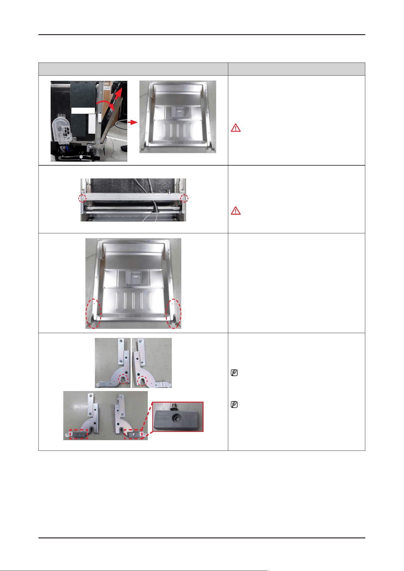
Disassembly and Reassembly _ 65
SAMSUNG PROPRIETARY. DO NOT COPY OR DISTRIBUTE WITHOUT PERMISSION
SAMSUNG PROPRIETARY. DO NOT COPY OR DISTRIBUTE WITHOUT PERMISSION
Photo Description
About 15˚
DOOR INNER ASSEMBLY
4. Do same work at the opposite side, and pull out the
DOOR INNER assembly to the direction of
about 15˚.
WARNING
Do not do this work without safety gloves.
It may cause injury from sharp edges.
5. Remove the 2 screws to remove the BRACKET DOOR
FRAME from the DOOR INNER.
-
Screws : DD81-02728A / 2 pcs
WARNING
Do not do this work without safety gloves.
It may cause injury from sharp edges.
6. Remove the 2 screws at each side to remove the
DOOR HINGE from the DOOR INNER.
-
Screws : DD81-02764A / 4 pcs
ASSY HOUSING
SUPPORT
7. Remove the GUIDE HINGE from the DOOR HINGE.
NOTE :
DOOR HINGE and GUIDE HINGE will serviced to
assembly only.
NOTE :
In case of Free standing models(DW70*****F*),
it need to disassemble ASSY HOUSING SUPPORT
also.
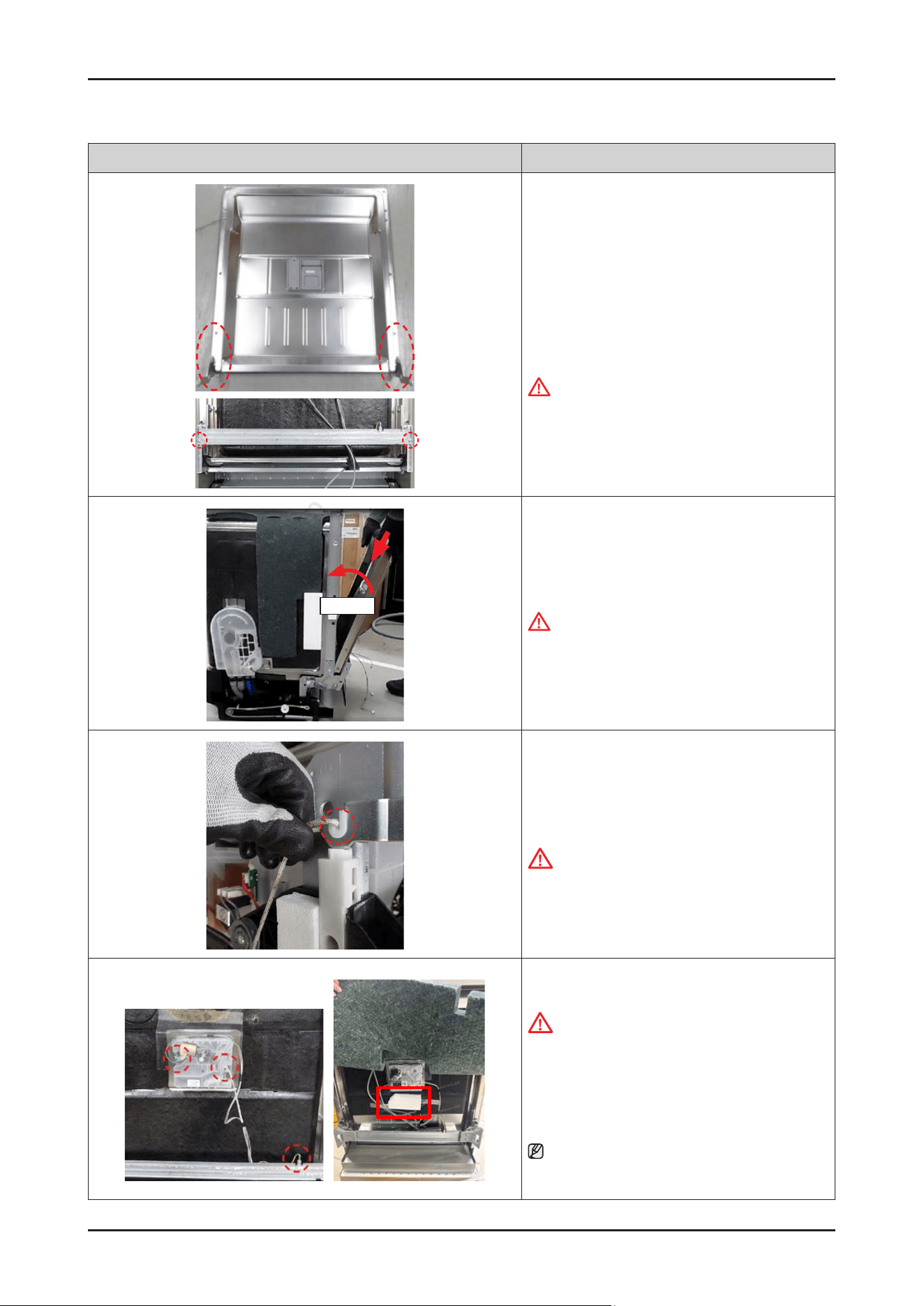
66 _ Disassembly and Reassembly
SAMSUNG PROPRIETARY. DO NOT COPY OR DISTRIBUTE WITHOUT PERMISSION
SAMSUNG PROPRIETARY. DO NOT COPY OR DISTRIBUTE WITHOUT PERMISSION
Photo Description
[ASSEMBLY]
1. Assemble the DOOR HINGE assembly and BRACKET
DOOR FRAME with machine screws.
-
Screws for DOOR HINGE assembly
-
Screws for BRACKET DOOR FRAME
WARNING
Do not do this work without safety gloves.
It may cause injury from sharp edges.
About 15˚
2. Fit the DOOR INNER assembly into the holder of the
TUB to lock the hook of DOOR HINGE.
WARNING
Do not do this work without safety gloves.
It may cause injury from sharp edges.
3. Put the HOLDER ROPE DOOR on the both side of
DOOR HINGE with the DOOR closed.
CAUTION
Be careful, hinge (spring) tension.
4. Connect 2 terminals of DETERGENT DISPENSER, and
a ground wire.
CAUTION
Make sure the Wire harness is not getting stuck in
other parts.
5. Please paste the white cotton removed from
the original inner door onto the new inner door.
NOTE :
The pasting position of white cotton is directly below the
dispenser, as shown in the red box on the left picture.
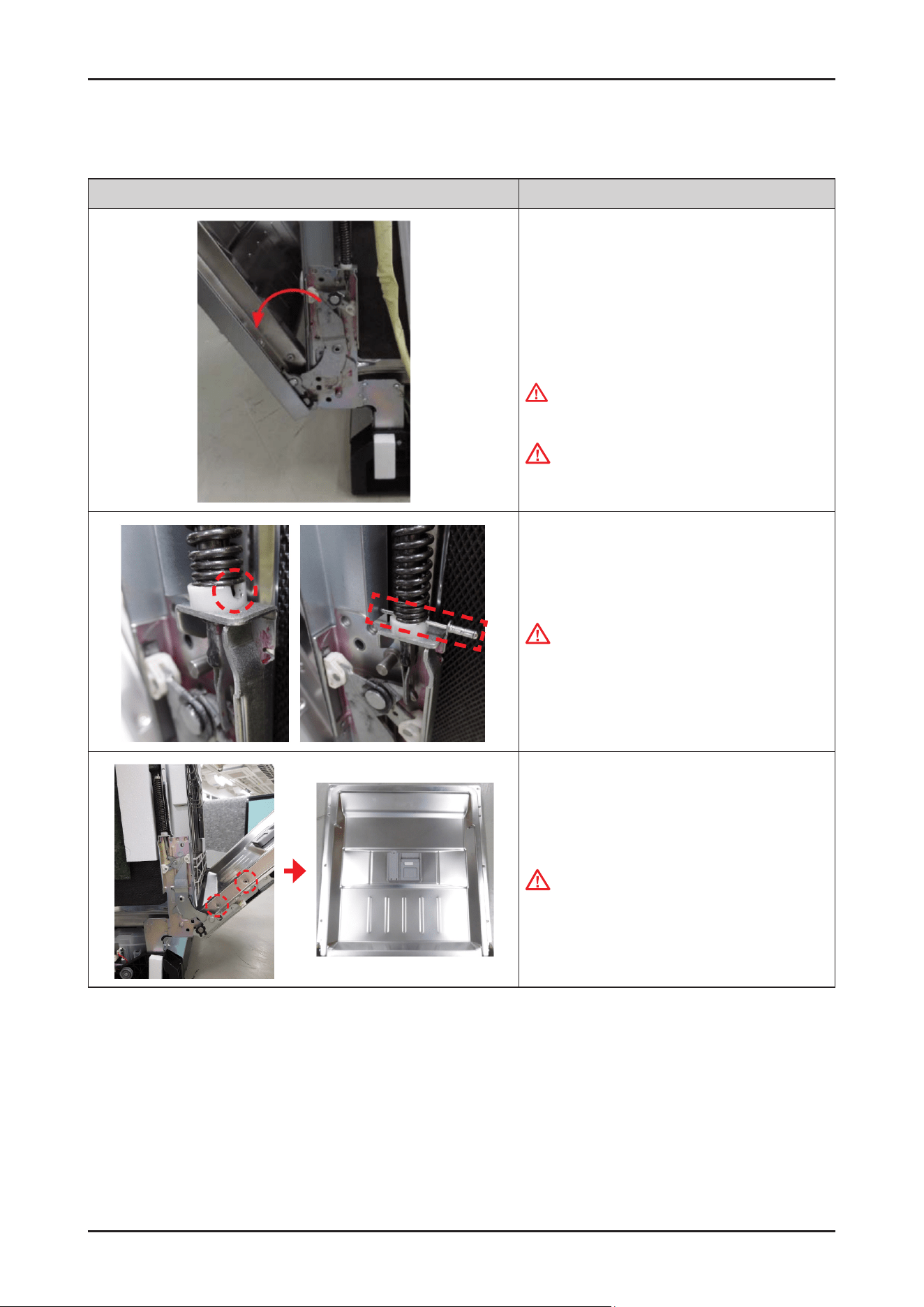
Disassembly and Reassembly _ 67
SAMSUNG PROPRIETARY. DO NOT COPY OR DISTRIBUTE WITHOUT PERMISSION
SAMSUNG PROPRIETARY. DO NOT COPY OR DISTRIBUTE WITHOUT PERMISSION
3-2-18. DOOR INNER / DOOR HINGE (EXCEPT DW70*****I*)
Photo Description
[DISASSEMBLY]
※ PREPARATION: Disassemble the DOOR OUTER,
CONTROL PANEL and
SIDE PANEL left & right.
1.
Open the door about 45˚
WARNING
Be sure to remove the power plug before servicing.
WARNING
Do not do this work without safety gloves.
It may cause injury from sharp edges.
2. Insert a pin to x the door spring.
CAUTION
Make sure to use a strong enough pin to endure the
spring force.
3. Remove 2 screws(at each side / Total 4 pcs) xing
DOOR INNER.
CAUTION:
Be careful not to dent the DOOR INNER during
disassembly.
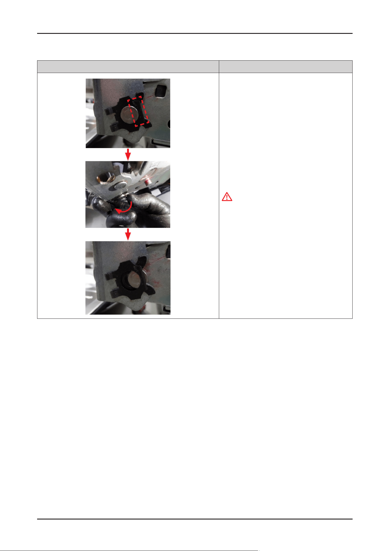
68 _ Disassembly and Reassembly
SAMSUNG PROPRIETARY. DO NOT COPY OR DISTRIBUTE WITHOUT PERMISSION
SAMSUNG PROPRIETARY. DO NOT COPY OR DISTRIBUTE WITHOUT PERMISSION
Photo Description
4. Remove the stopper carefully.
WARNING
Do not do this work without safety gloves.
It may cause injury from sharp edges.
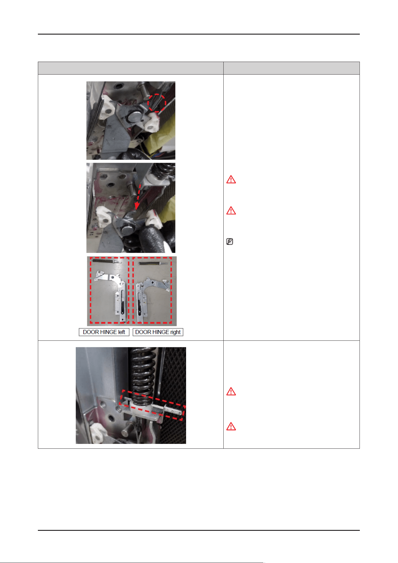
Disassembly and Reassembly _ 69
SAMSUNG PROPRIETARY. DO NOT COPY OR DISTRIBUTE WITHOUT PERMISSION
SAMSUNG PROPRIETARY. DO NOT COPY OR DISTRIBUTE WITHOUT PERMISSION
Photo Description
5. Remove the ASSY HINGE from the DOOR
SPRING.
WARNING
Do not do this work without safety gloves.
It may cause injury from sharp edges.
WARNING
Be careful not to pop out the spring during
disassembly. It may cause serious injury.
NOTE :
DOOR HINGE will be serviced with DOOR INNER
together by DOOR INNER assembly.
(SVC ASSY-INNER DOOR).
[ASSEMBLY]
1. Pull the spring enough, and insert a pin to x the door
spring.
CAUTION
Make sure to use a strong enough pin to endure the
spring force.
WARNING
Be careful not to pop out the spring.
It may cause serious injury.
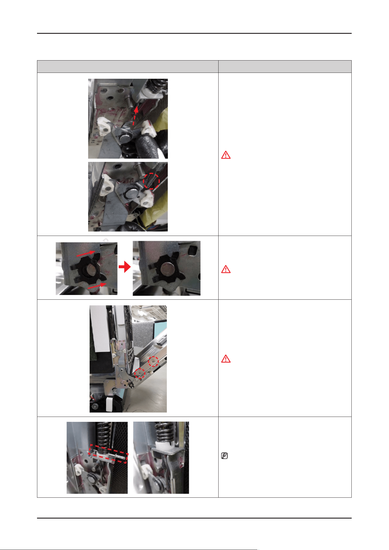
70 _ Disassembly and Reassembly
SAMSUNG PROPRIETARY. DO NOT COPY OR DISTRIBUTE WITHOUT PERMISSION
SAMSUNG PROPRIETARY. DO NOT COPY OR DISTRIBUTE WITHOUT PERMISSION
Photo Description
2. Hang the DOOR HINGE to the hole of the spring.
WARNING
Do not do this work without safety gloves.
It may cause injury from sharp edges.
3. Assemble the stopper carefully.
WARNING
Do not do this work without safety gloves.
It may cause injury from sharp edges.
4. Fasten 2 screws(at each side / Total 4 pcs) to x
DOOR INNER.
CAUTION
Be careful not to dent the DOOR INER during
assembly.
5. Remove the pin.
NOTE :
After servicing DOOR INNER assembly, assemble
WIRE HARNESS, DOOR OUTER, CONTROL PANEL and
SIDE PANEL.
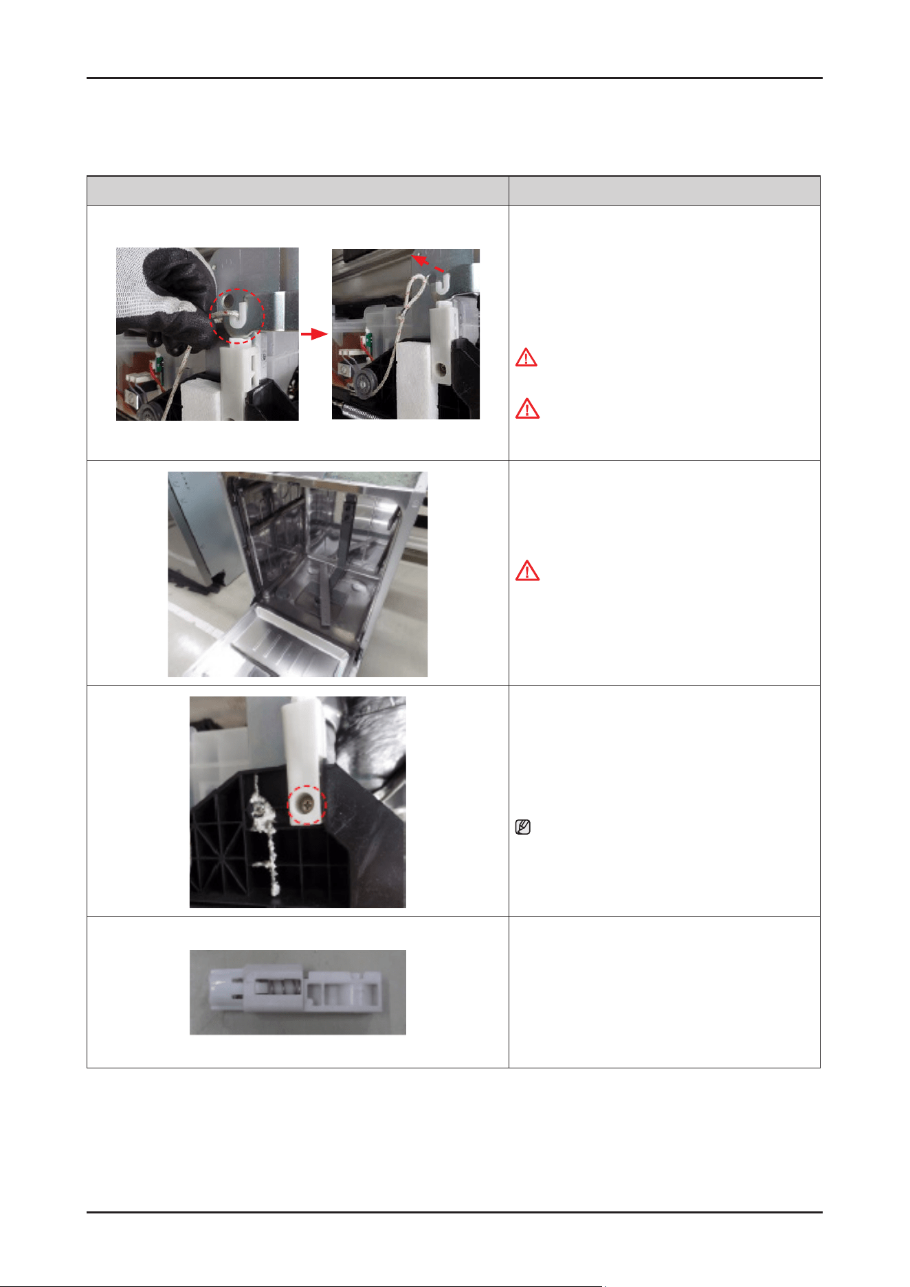
Disassembly and Reassembly _ 71
SAMSUNG PROPRIETARY. DO NOT COPY OR DISTRIBUTE WITHOUT PERMISSION
SAMSUNG PROPRIETARY. DO NOT COPY OR DISTRIBUTE WITHOUT PERMISSION
3-2-19. DAMPER DOOR
Photo Description
[DISASSEMBLY]
※ PREPARATION: Disassemble SIDE PANEL
left & right.
1.
Remove HOLDER ROPE DOOR from the DOOR
HINGE left & right with the DOOR closed.
WARNING
Be sure to remove the power plug before servicing.
CAUTION
Pay attention to DOOR drop after removing the rope.
It may cause injury.
2. Open the dishwasher’s DOOR.
CAUTION
Be careful to avoid injury from the DOOR drop
without the HOLDER ROPE DOOR.
3. Remove 1 screw to remove the DAMPER DOOR from
the BASE.
NOTE : Do same work at the opposite side.
4. Remove the DAMPER DOOR.
[ASSEMBLY]
※ Reassembly is the reverse order of disassembly.
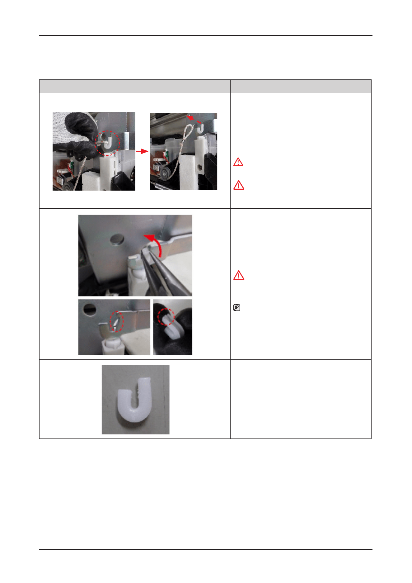
72 _ Disassembly and Reassembly
SAMSUNG PROPRIETARY. DO NOT COPY OR DISTRIBUTE WITHOUT PERMISSION
SAMSUNG PROPRIETARY. DO NOT COPY OR DISTRIBUTE WITHOUT PERMISSION
3-2-20. HOLDER HINGE
Photo Description
[DISASSEMBLY]
※ PREPARATION: Disassemble SIDE PANEL
left & right.
1.
Remove HOLDER ROPE DOOR from the DOOR
HINGE left & right with the DOOR closed.
WARNING
Be sure to remove the power plug before servicing.
CAUTION
Pay attention to DOOR drop after removing the rope.
It may cause injury.
2. Remove HOLDER HINGE from the DOOR HINGE.
CAUTION
Be careful to avoid injury from the DOOR drop
without the HOLDER ROPE DOOR.
NOTE : Rotate the HOLDER HINGE to release from
hook.
[ASSEMBLY]
※ Reassembly is the reverse order of disassembly.
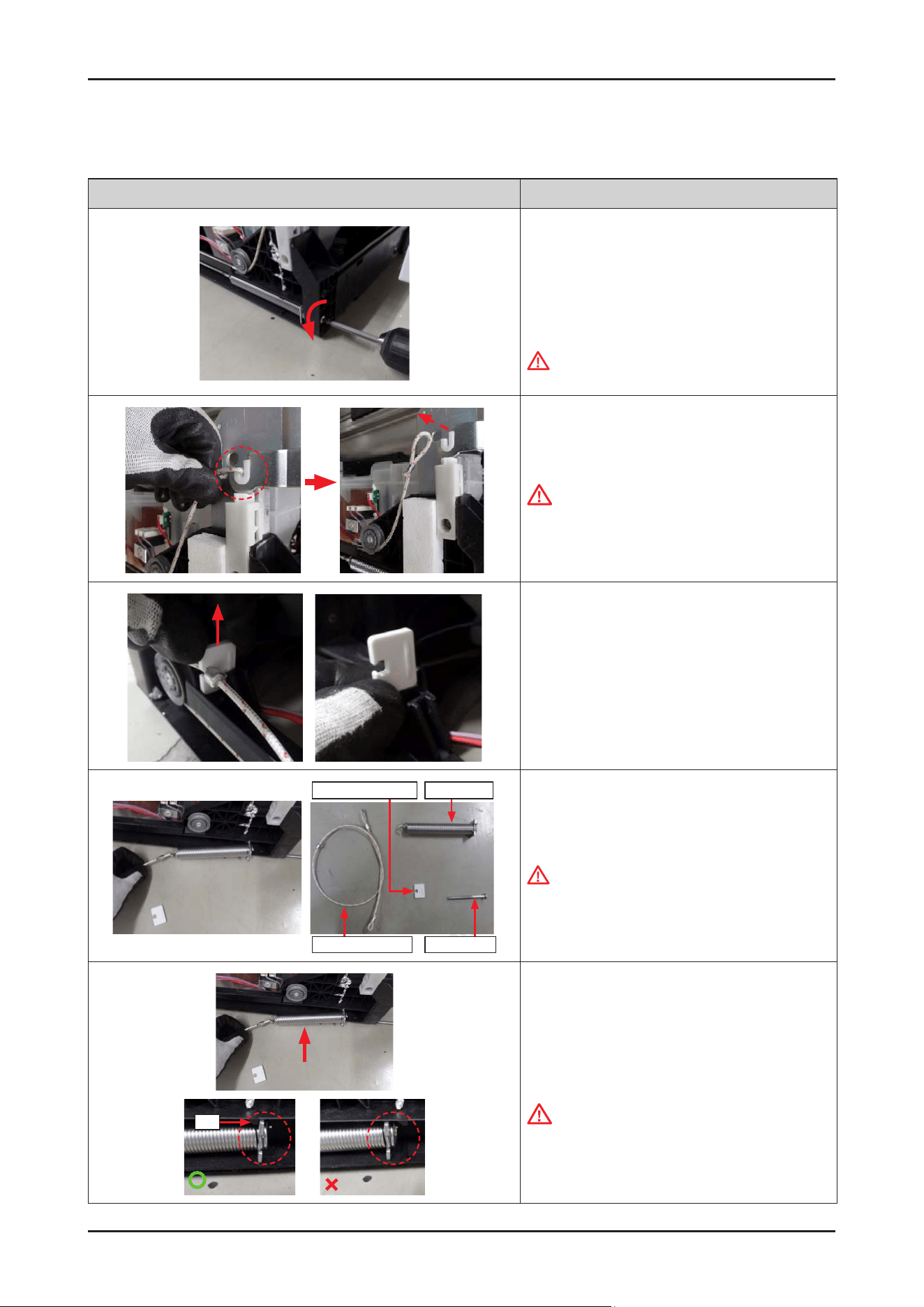
Disassembly and Reassembly _ 73
SAMSUNG PROPRIETARY. DO NOT COPY OR DISTRIBUTE WITHOUT PERMISSION
SAMSUNG PROPRIETARY. DO NOT COPY OR DISTRIBUTE WITHOUT PERMISSION
3-2-21. HOLDER ROPE DOOR / SPRING DOOR
Photo Description
[DISASSEMBLY]
※ PREPARATION: Disassemble SIDE PANEL left & right.
1. Release the SHAFT SPRING(screw) to disassemble
the SPRING DOOR
(counter-clockwise).
WARNING
Be sure to remove the power plug before servicing.
2. Remove HOLDER ROPE DOOR from the DOOR
HINGE left & right with the DOOR closed.
CAUTION
Pay attention to DOOR drop after removing the
HOLDER ROPE DOOR. It may cause injury.
3. Remove the STOPPER ROPE DOOR upward.
Holder Rope Door Shaft Spring
Spring DoorStopper Rope Door
4. Remove the HOLDER ROPE DOOR and the SPRING
DOOR from the BASE.
WARNING
Ropes and springs should not be replaced with parts
other than OEMs, and ropes should not be extended
or cut in any way.
Rib
Rib
[ASSEMBLY]
1.
Fit the SPRING DOOR into the BASE (both sides).
CAUTION
Pay attention to hang the spring on the rib.
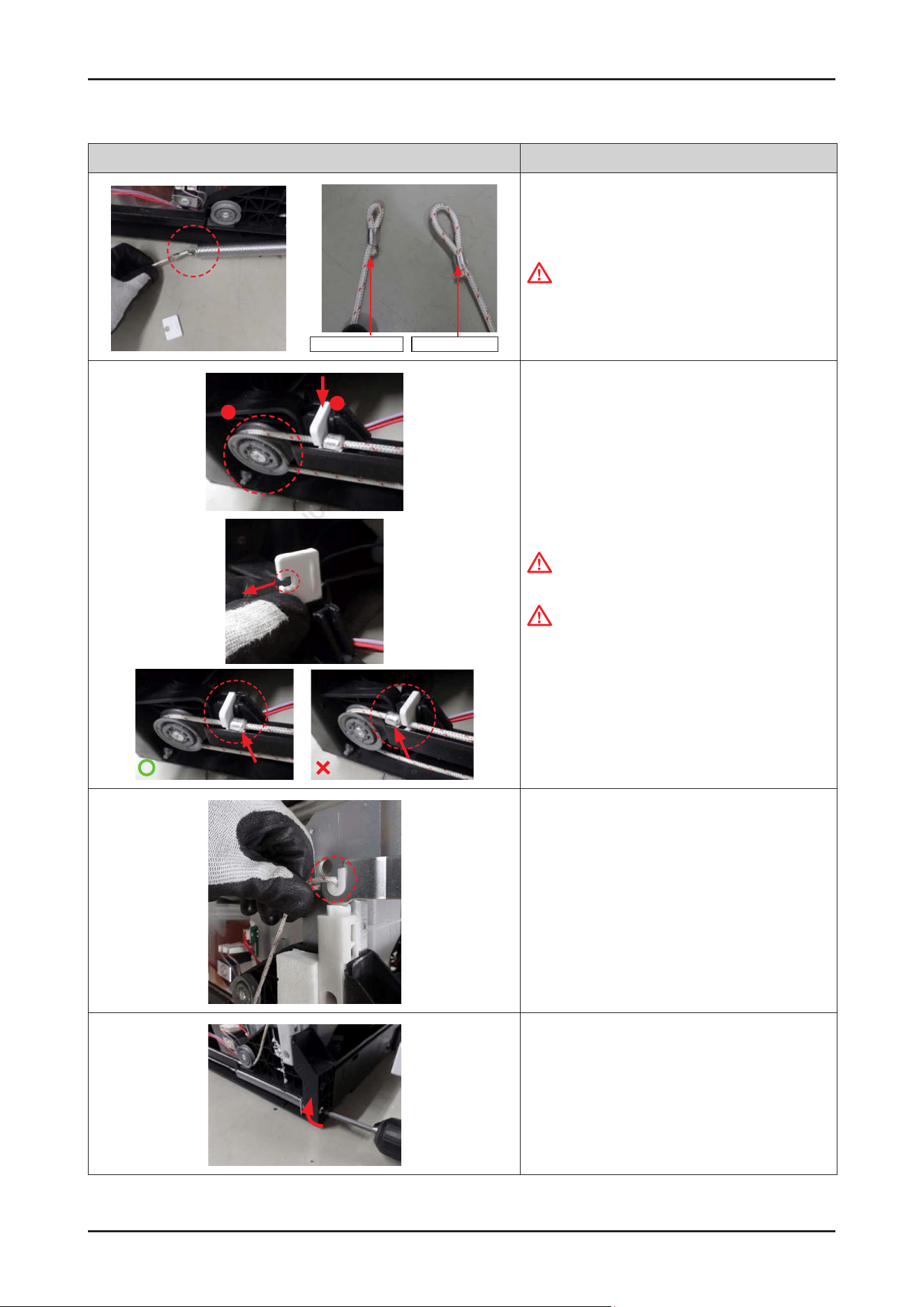
74 _ Disassembly and Reassembly
SAMSUNG PROPRIETARY. DO NOT COPY OR DISTRIBUTE WITHOUT PERMISSION
SAMSUNG PROPRIETARY. DO NOT COPY OR DISTRIBUTE WITHOUT PERMISSION
Photo Description
Spring direction Hinge direction
2. Hang HOLDER ROPE DOOR on the tail of spring.
CAUTION
Pay attention to hang the rope to spring to the small
loop.
1
2
3. Hang the rope on the roller, and t the STOPPER
ROPE DOOR downward.
CAUTION
Make sure that the hole faces outward.
CAUTION
The iron part of HOLDER ROPE DOOR need to be
hang to stopper.
4. Fit the rope onto the both sides of DOOR HINGE
with the DOOR closed.
5. Fasten the SHAFT SPRING(screw) to assemble
SPRING DOOR (clockwise).
* After assembled, adjust the tension of SPRING DOOR
to open/close the DOOR appropriately.
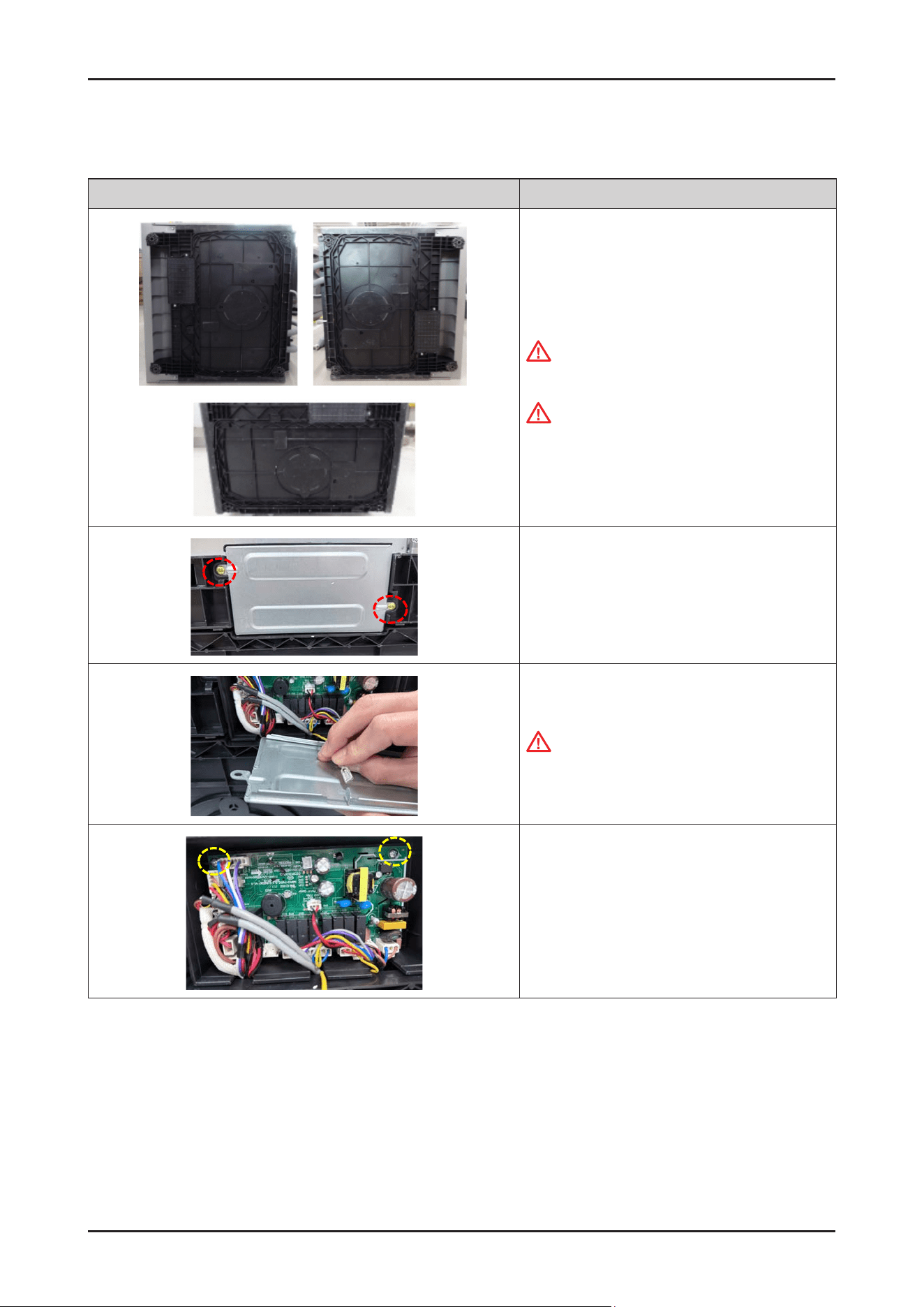
Disassembly and Reassembly _ 75
SAMSUNG PROPRIETARY. DO NOT COPY OR DISTRIBUTE WITHOUT PERMISSION
SAMSUNG PROPRIETARY. DO NOT COPY OR DISTRIBUTE WITHOUT PERMISSION
3-2-22. MAIN PBA
Photo Description
[DISASSEMBLY]
1. Lay down the dishwasher on the back or both sides.
Warning
Be sure to remove the power plug before servicing.
CAUTION
Make sure to lay down the dishwasher carefully.
If it falls carelessly, It may cause damage.
2. Remove the 2 screws to remove the COVER PBA.
3. Remove a ground wire connector from
COVER PBA.
CAUTION
This connector is P-Lock type.
Press the buckle, and pull out the terminal to
remove.
4. Remove the 2 screws to take off the MAIN PBA.
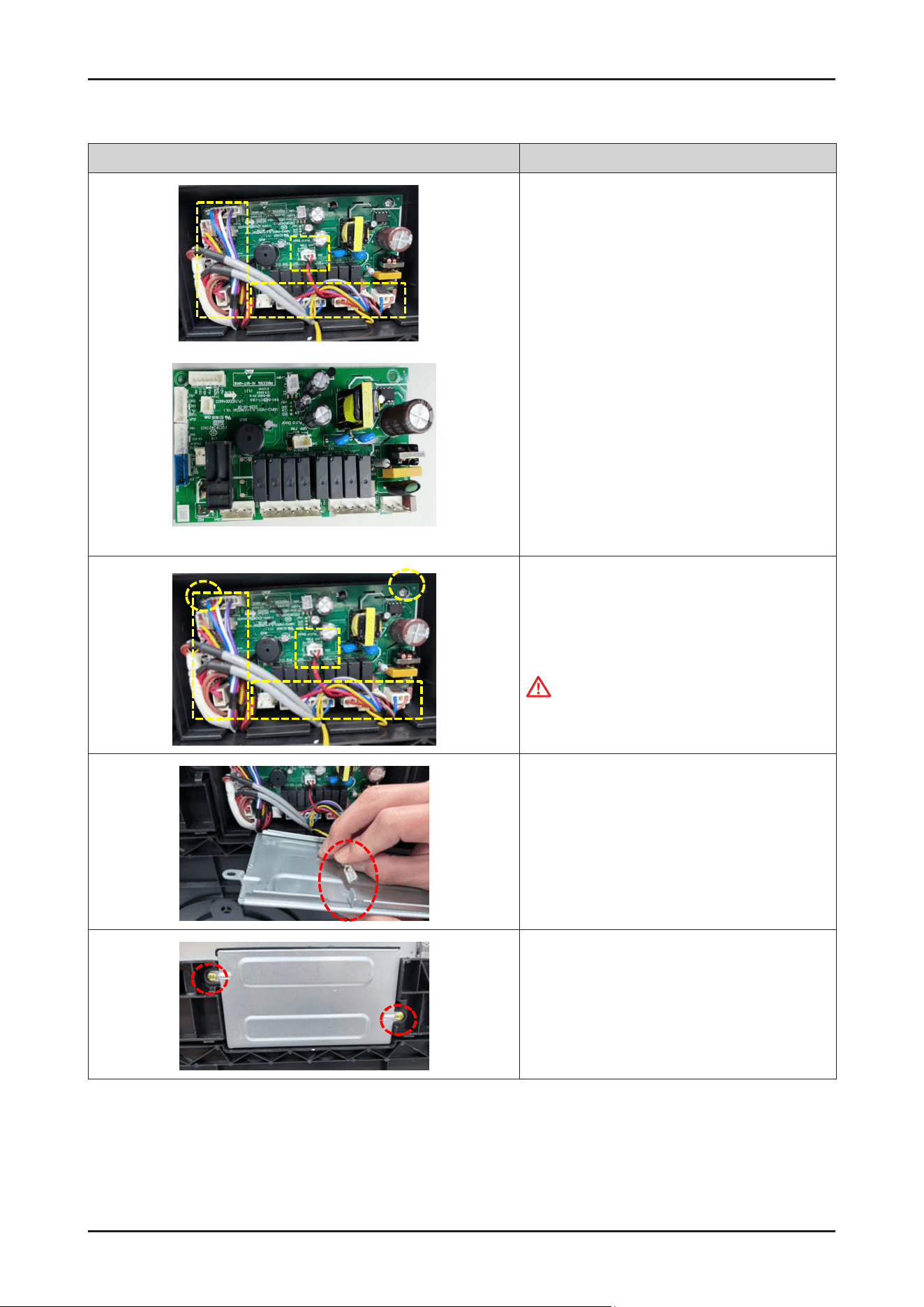
76 _ Disassembly and Reassembly
SAMSUNG PROPRIETARY. DO NOT COPY OR DISTRIBUTE WITHOUT PERMISSION
SAMSUNG PROPRIETARY. DO NOT COPY OR DISTRIBUTE WITHOUT PERMISSION
Photo Description
Main PBA
5. Remove the wire connectors.
[ASSEMBLY]
1. Connect the Wire connectors, and fasten
2 screws to x PBA.
CAUTION
Make sure the Wire harness is not getting stuck in
other parts.
2. Fasten the ground wire connector to x COVER PBA.
3. Fasten the 2 screws to x COVER PBA
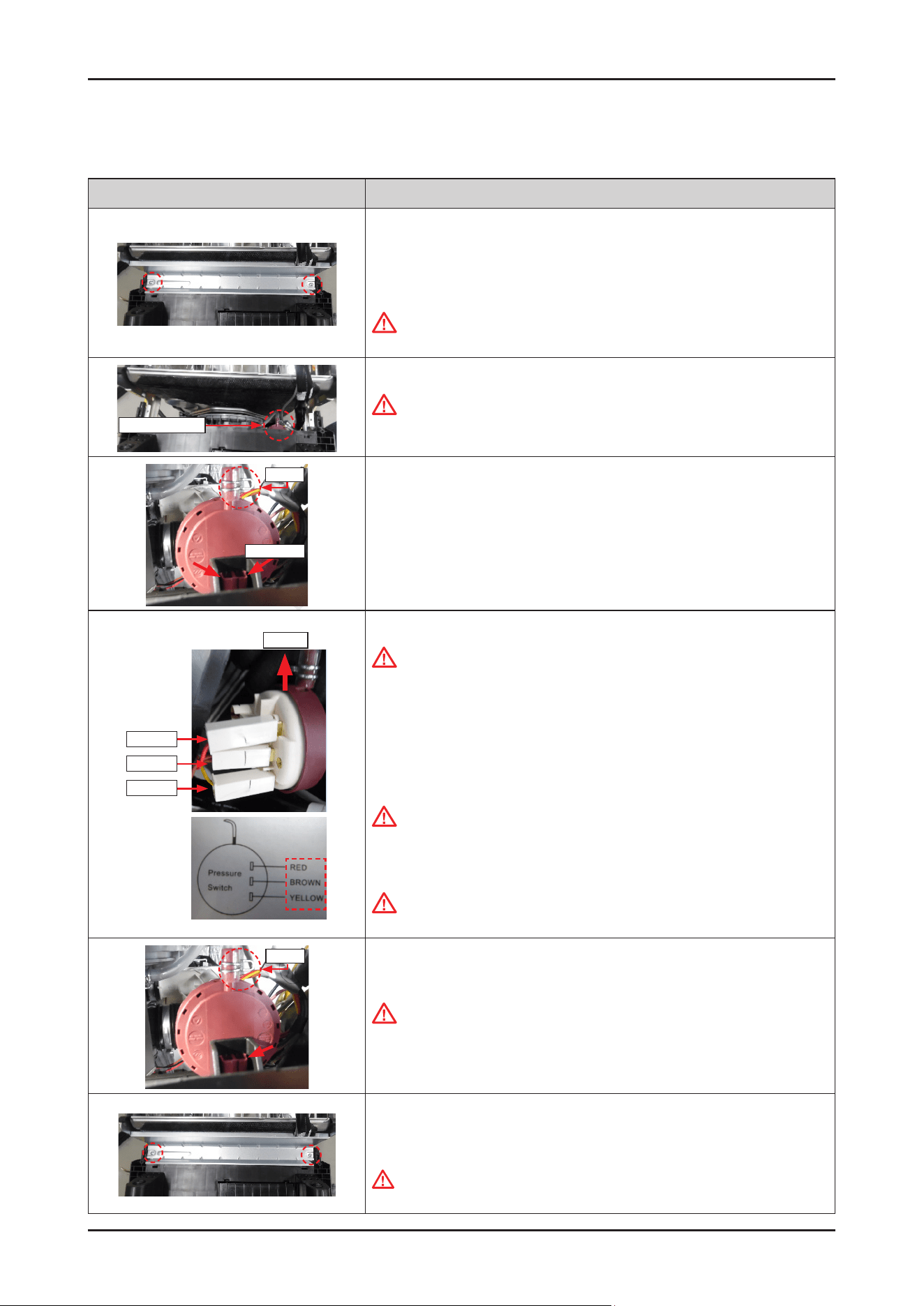
Disassembly and Reassembly _ 77
SAMSUNG PROPRIETARY. DO NOT COPY OR DISTRIBUTE WITHOUT PERMISSION
SAMSUNG PROPRIETARY. DO NOT COPY OR DISTRIBUTE WITHOUT PERMISSION
3-2-23. PRESSURE SWITCH
Photo Description
[DISASSEMBLY]
※ PREPARATION: Disassemble the DOOR OUTER.
1.
Remove the 2 screws of FRAME FRONT.
Warning
Be sure to remove the power plug before servicing.
Pressure Switch
2. Remove the FRAME FRONT.
Warning
Do not do this work without safety gloves.
It may cause injury from sharp edges.
Clamp
Push hooks
3. Unclip the clamp and release the hook with a long-nose pliers.
Upside
RED
BROWN
YELLOW
4. Remove the 3 wire connectors from the PRESSURE SWITCH.
CAUTION
Make sure to reassemble the wire connector to the correct positions.
Please refer to the label that is attached to the wire harness.
(RED-BROWN-YELLOW from the upper position)
[ASSEMBLY]
1.
Connect the 3 wire connectors to PRESSURE SWITCH.
CAUTION
Make sure to reassemble the wire connector to the correct positions.
Please refer to the label that is attached to the wire harness.
(RED-BROWN-YELLOW from the upper position)
CAUTION
Make sure the wire harness is not getting stuck in other parts.
Clamp
2. Lock the hook, and the assemble the PRESSURE HOSE with the clamp.
CAUTION
Make sure to insert the hoses correctly.
The switch cannot detect the pressure correctly when it’s misassembled.
3. Assemble the FRAME FRONT with 2 machine screws.
-
Machine Screws: DD81-02728A
WARNING
Do not do this work without safety gloves. It may cause injury from sharp edges.
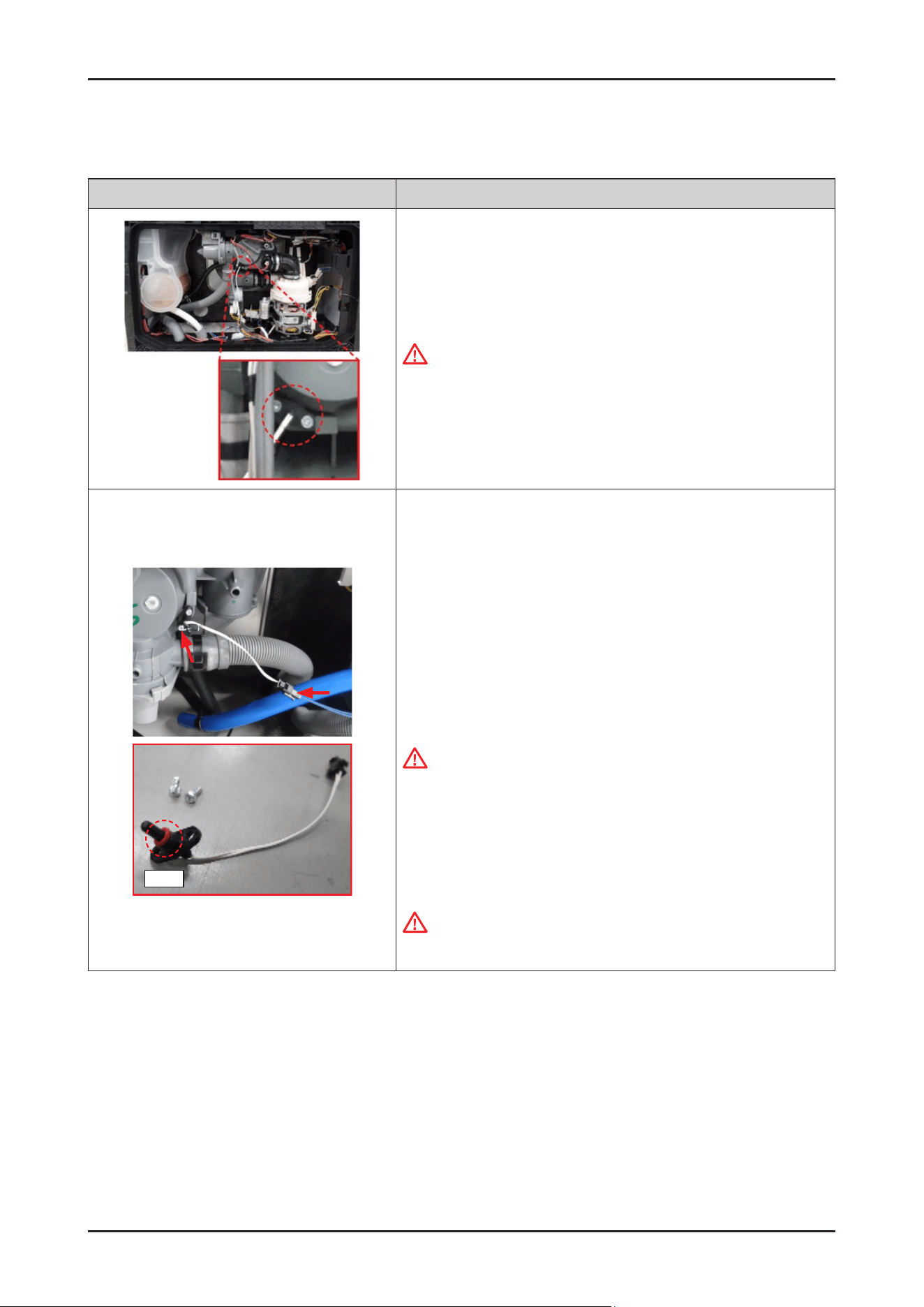
78 _ Disassembly and Reassembly
SAMSUNG PROPRIETARY. DO NOT COPY OR DISTRIBUTE WITHOUT PERMISSION
SAMSUNG PROPRIETARY. DO NOT COPY OR DISTRIBUTE WITHOUT PERMISSION
3-2-24. THERMISTOR
Photo Description
[DISASSEMBLY]
1. Remove the COVER BASE.
Warning
Be sure to remove the power plug before servicing.
←
The location of THERMISTOR.
Seal
2. Remove the wire harness of THERMISTOR.
3. Release the 2 screws xing the THERMISTOR with the CASE SUMP.
-
screw: DD81-02738A / 2 pcs
4.
Remove the THERMISTOR from the CASE SUMP.
[ASSEMBLY]
1.
Fit the THERMISTOR into the SUMP.
CAUTION
Be careful not to lose the seal of THERMISTOR.
2.
Fasten the 2 screws to x the THERMISTOR.
-
screw: DD81-02738A / 2 pcs
3.
Connect the wire harness of the THERMISTOR.
CAUTION
Make sure the Wire harness is not getting stuck in other parts.
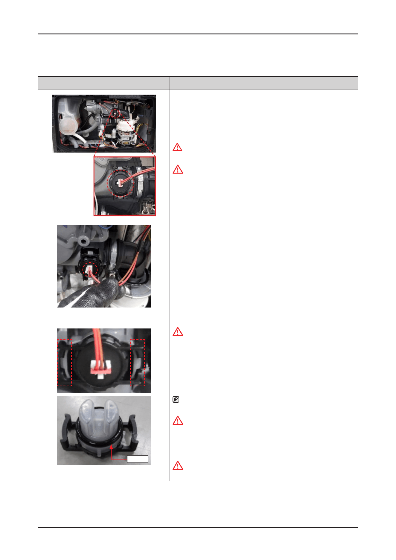
Disassembly and Reassembly _ 79
SAMSUNG PROPRIETARY. DO NOT COPY OR DISTRIBUTE WITHOUT PERMISSION
SAMSUNG PROPRIETARY. DO NOT COPY OR DISTRIBUTE WITHOUT PERMISSION
3-2-25. TURBIDITY SENSOR
Photo Description
[DISASSEMBLY]
1. Remove the COVER BASE.
WARNING
Be sure to remove the power plug before servicing.
CAUTION
Make sure the Wire harness is not getting stuck in other parts.
← The location of the TURBIDITY SENSOR
2. Remove the wire harness of the TURBIDITY SENSOR.
Seal
3. Remove the TURBIDITY SENSOR releasing both sides of hooks.
CAUTION
Release the hooks carefully. It can be broken if it’s serviced carelessly.
[ASSEMBLY]
1.
Fit the TURBIDITY SENSOR into the SUMP.
NOTE :
To assemble the sensor easily, put some water on its seal.
CAUTION
Make sure to lock the hook. There's risks of leakage or poor performance
when it’s misassembled.
2.
Connect the wire harness of the TURBIDITY SENSOR.
CAUTION
Make sure the Wire harness is not getting stuck in other parts.
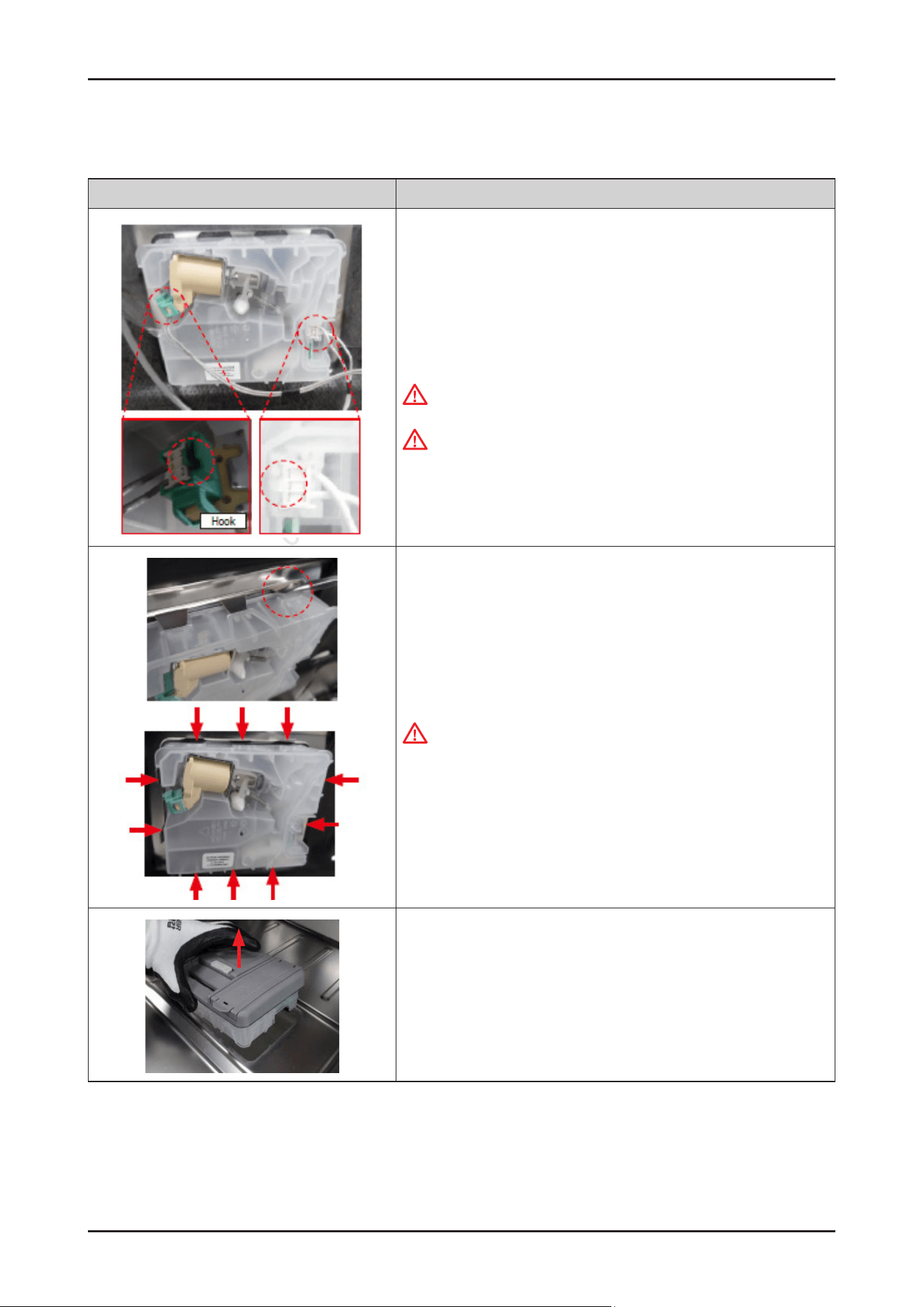
80 _ Disassembly and Reassembly
SAMSUNG PROPRIETARY. DO NOT COPY OR DISTRIBUTE WITHOUT PERMISSION
SAMSUNG PROPRIETARY. DO NOT COPY OR DISTRIBUTE WITHOUT PERMISSION
3-2-26. DETERGENT DISPENSER
Photo Description
[DISASSEMBLY]
※ PREPARATION: Disassemble DOOR OUTER.
1.
Remove the 2 terminals that connected to DETERGENT DISPENSER.
Warning
Be sure to remove the power plug before servicing.
CAUTION
Pay attention to hook of terminals.
2. Tilt the 10 hooks outward to disassemble DETERGENT DISPENSER with a
at-head screwdriver.
Warning
Do not this work without safety gloves.
It may cause injury from sharp edges.
3. Disassemble the DETERGENT DISPENSER carefully.
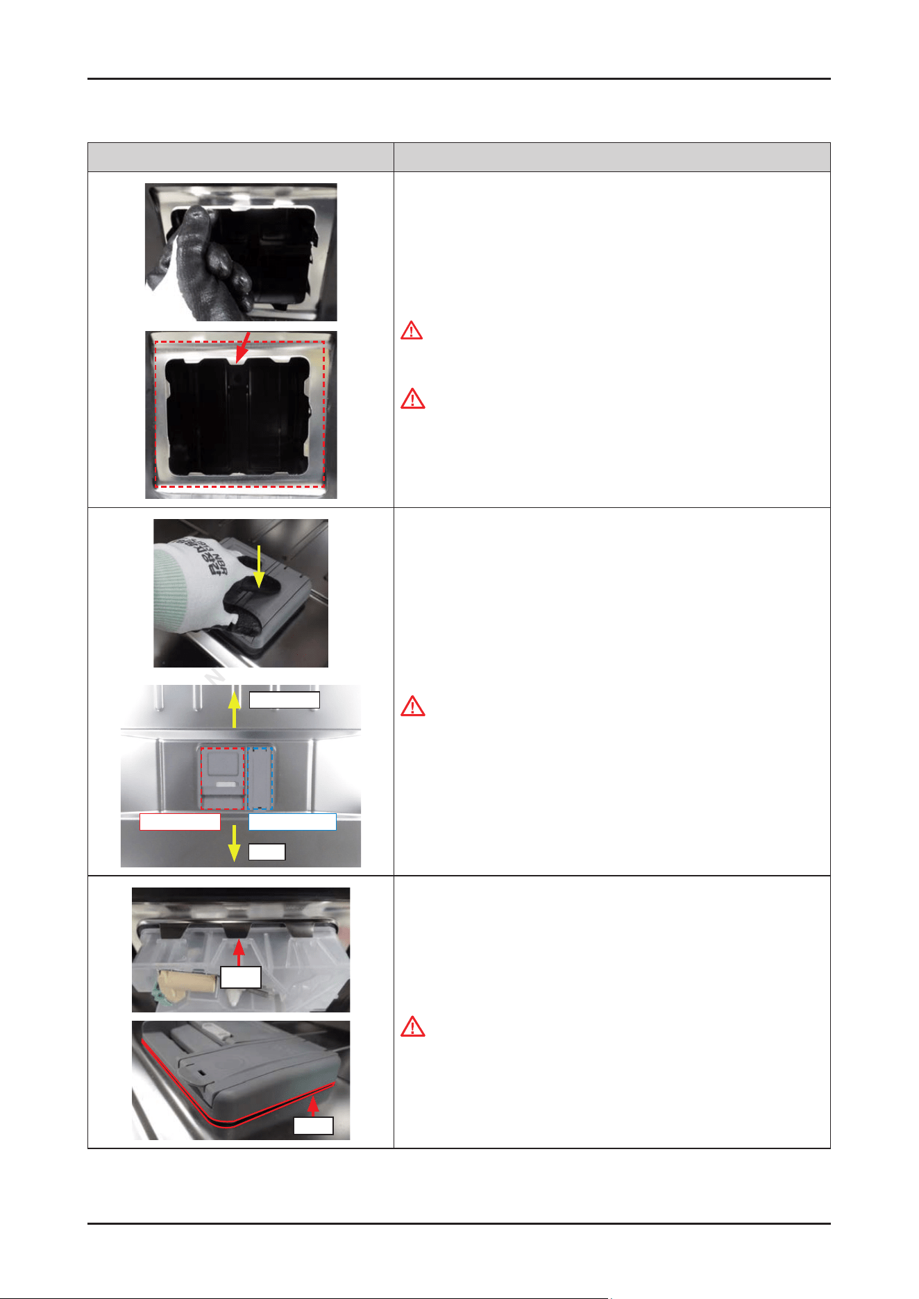
Disassembly and Reassembly _ 81
SAMSUNG PROPRIETARY. DO NOT COPY OR DISTRIBUTE WITHOUT PERMISSION
SAMSUNG PROPRIETARY. DO NOT COPY OR DISTRIBUTE WITHOUT PERMISSION
Photo Description
[ASSEMBLY]
1.
Tilt the 10 hooks a little inward.
WARNING
Do not this work without safety gloves.
It may cause injury from sharp edges.
CAUTION
Pay attention to hook of terminals.
Dishwasher
Right: Rinse Aid
User
Left: Detergent
2. Assemble the DETERGENT DISPENSER to DOOR INNER.
It will be assembled with a click.
CAUTION
Pay attention to the direction of the DETERGENT DISPENSER.
Rib
Seal
3. Check if the hooks are locked correctly.
The hook must be on the rib.
CAUTION
Check if there’s any gap on the seal.
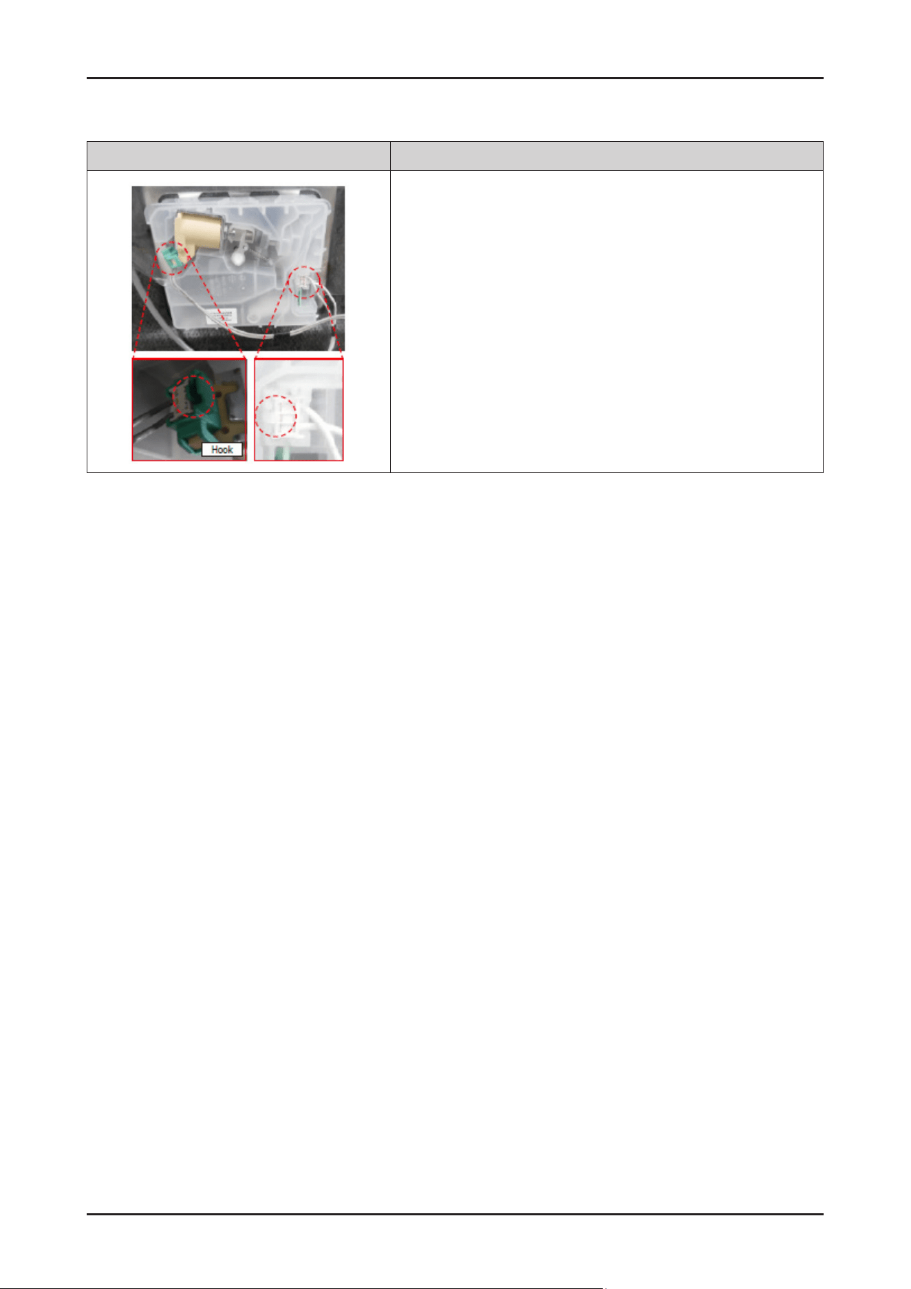
82 _ Disassembly and Reassembly
SAMSUNG PROPRIETARY. DO NOT COPY OR DISTRIBUTE WITHOUT PERMISSION
SAMSUNG PROPRIETARY. DO NOT COPY OR DISTRIBUTE WITHOUT PERMISSION
Photo Description
4. Connect the 2 terminals.
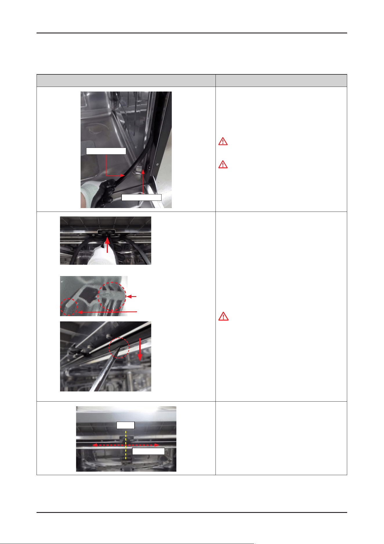
Disassembly and Reassembly _ 83
SAMSUNG PROPRIETARY. DO NOT COPY OR DISTRIBUTE WITHOUT PERMISSION
SAMSUNG PROPRIETARY. DO NOT COPY OR DISTRIBUTE WITHOUT PERMISSION
3-2-27. SEAL TUB PACKING
Photo Description
Seal tub packing
Bracket seal tub
[DISASSEMBLY]
1.
Remove the old seal from the BRACKET SEAL TUB.
WARNING
Be sure to remove the power plug before servicing.
WARNING
Be careful to touch the BRACKET SEAL TUB after
removed the seal.
It may cause injury from sharp edges.
Insert to Bracket seal Tub
Seal tip
Seal tip faces to inside
[ASSEMBLY]
1.
Put some water on new SEAL TUB PACKING to
assemble it easily. Fold the SEAL TUB PACKING in
half with the tip of the seal facing inward.
CAUTION
Pay attention to the direction of seal. If it is
assembled in reverse, it may cause leakage of steam
or water.
Center
About 20 cm
2 Assemble the SEAL TUB PACKING to center of the
BRACKET SEAL TUB.
Press seal about 20 cm (red dotted line) on both sides
based on the center line.
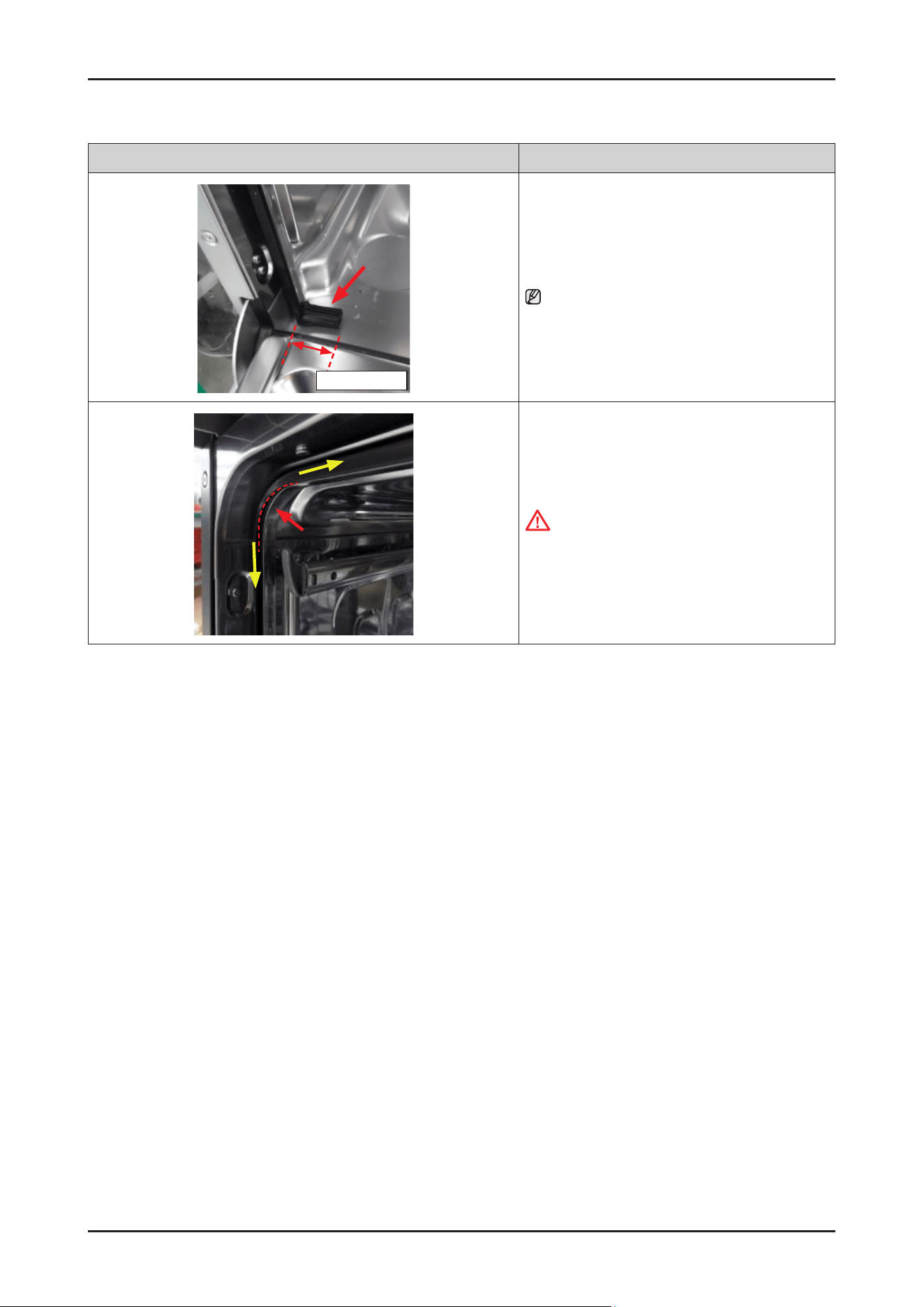
84 _ Disassembly and Reassembly
SAMSUNG PROPRIETARY. DO NOT COPY OR DISTRIBUTE WITHOUT PERMISSION
SAMSUNG PROPRIETARY. DO NOT COPY OR DISTRIBUTE WITHOUT PERMISSION
Photo Description
About 3~4 cm
3. Put Seal in the left & right side of the bottom.
NOTE :
The folded seal is about 3~4 cm long.
4. Press the seal from the top corner toward remaining
side.
CAUTION
Pay attention to assemble not to deform the seal
tip at the corner. If the gap is opened, it may cause
steam leakage.
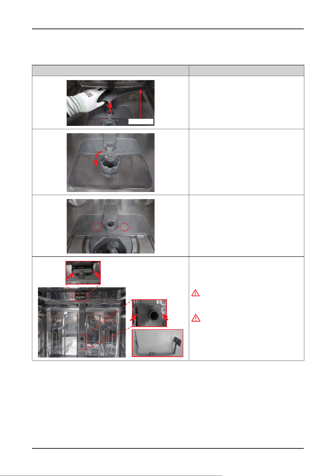
Disassembly and Reassembly _ 85
SAMSUNG PROPRIETARY. DO NOT COPY OR DISTRIBUTE WITHOUT PERMISSION
SAMSUNG PROPRIETARY. DO NOT COPY OR DISTRIBUTE WITHOUT PERMISSION
3-2-28. ROTOR LOWER / ASSY DUCT NOZZLE
Photo Description
Rotor lower
[DISASSEMBLY]
1.
Open the dishwasher's door, and remove the ROTOR
LOWER.
2. Turn the COARSE FILTER counter-clockwise to unlock
the lter assembly.
3. Remove the 2 screws to take off ASSY DUCT NOZZLE.
-
Screws: DD81-02718A / 2 pcs
4. Release the hooks from tub holders.
WARNING
Do not do this work without safety gloves.
It may cause injury from sharp edges.
CAUTION
Make sure to reassemble to the correct location.
There's risks of leakage or poor performance when
it’s misassembled.
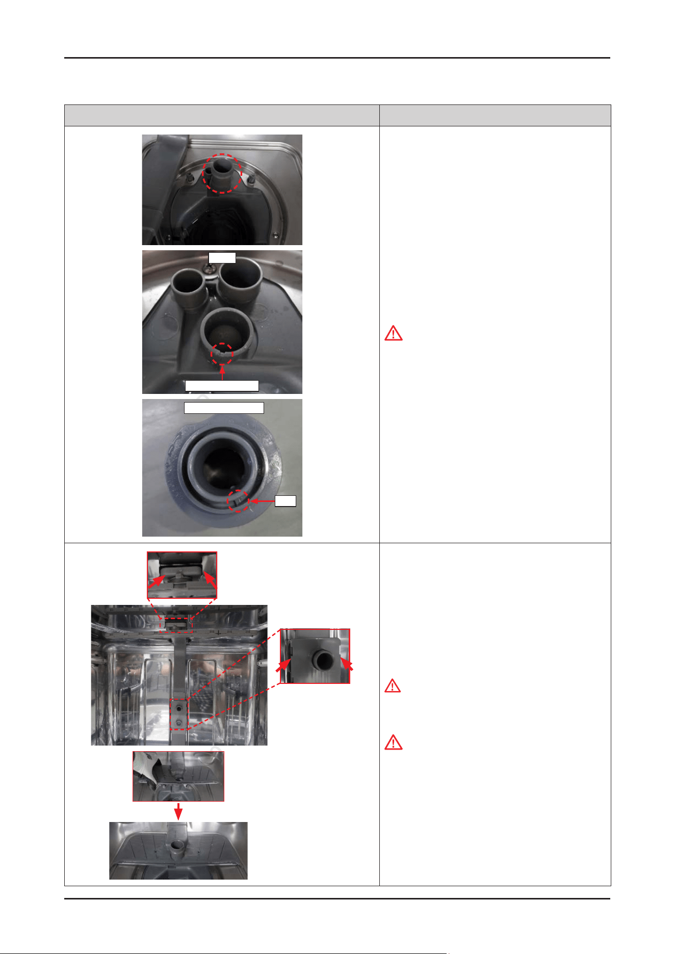
86 _ Disassembly and Reassembly
SAMSUNG PROPRIETARY. DO NOT COPY OR DISTRIBUTE WITHOUT PERMISSION
SAMSUNG PROPRIETARY. DO NOT COPY OR DISTRIBUTE WITHOUT PERMISSION
Photo Description
Sump
Guide of Holder
Bottom of Holder
Rib
[ASSEMBLY]
1.
Fit the HOLDER ROTOR LOWER on the SUMP.
CAUTION
Pay attention to assemble the HOLDER ROTOR
LOWER correctly.
There's risks of leakage or poor performance when
it’s misassembled.
2. Assemble the ASSY DUCT NOZZLE to hooks and on
the HOLDER ROTOR LOWER.
WARNING
Do not do this work without safety gloves. It may
cause injury from sharp edges.
CAUTION
Make sure to reassemble to the correct location.
There's risks of leakage or poor performance when
it’s misassembled.
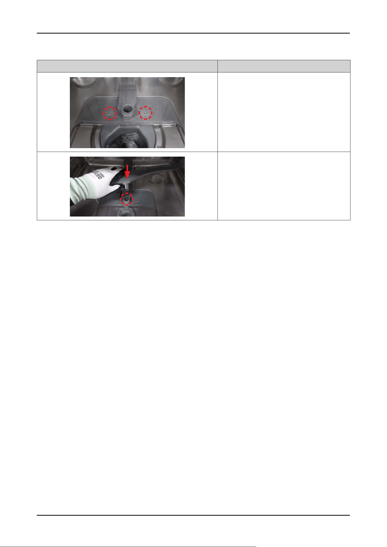
Disassembly and Reassembly _ 87
SAMSUNG PROPRIETARY. DO NOT COPY OR DISTRIBUTE WITHOUT PERMISSION
SAMSUNG PROPRIETARY. DO NOT COPY OR DISTRIBUTE WITHOUT PERMISSION
Photo Description
3. Fasten 2 screws to t the ASSY DUCT NOZZLE.
-
Screws: DD81-02718A / 2 pcs
4. Fit the ROTOR LOWER onto the HOLDER ROTOR
LOWER.
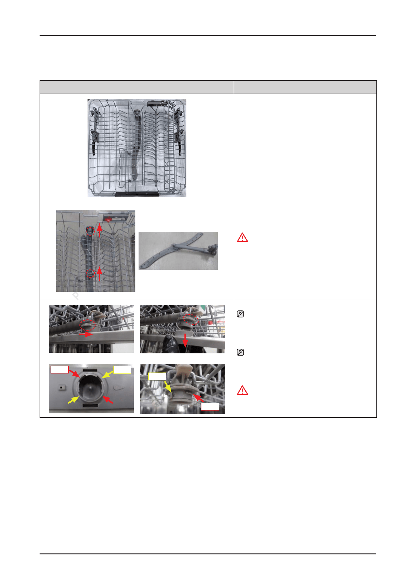
88 _ Disassembly and Reassembly
SAMSUNG PROPRIETARY. DO NOT COPY OR DISTRIBUTE WITHOUT PERMISSION
SAMSUNG PROPRIETARY. DO NOT COPY OR DISTRIBUTE WITHOUT PERMISSION
3-2-29. ASSY ROTOR MIDDLE
Photo Description
[DISASSEMBLY]
1. Open the dishwasher’s DOOR, and take off the
BASKET MIDDLE.
2. Release 2 hooks to take off ASSY ROTOR MIDDLE
from the BASKET MIDDLE.
CAUTION
Be careful not to break the hooks.
[ASSEMBLY]
1.
Reassembly is the reverse order of disassembly.
long
short
long
short
NOTE :
To disassemble the ROTOR MIDDLE only,
loosen the HOLDER ROTOR MIDDLE in a
counter-clockwise direction.
NOTE :
Make sure to t the hook to the right location of
ROTOR MIDDLE.
WARNING
Since the middle of the rotor may be xed due to the
limescale, completely separate it from the machine.
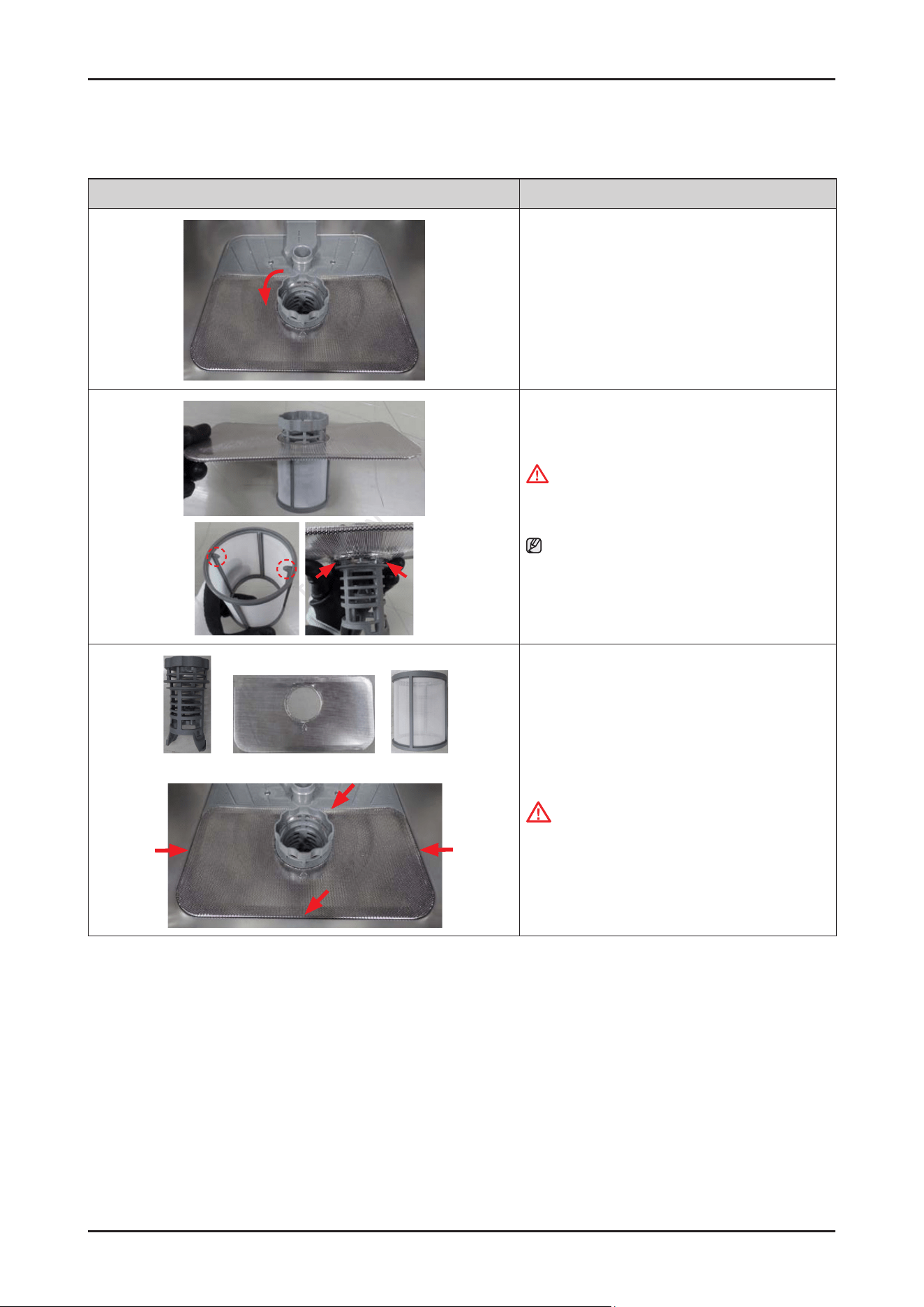
Disassembly and Reassembly _ 89
SAMSUNG PROPRIETARY. DO NOT COPY OR DISTRIBUTE WITHOUT PERMISSION
SAMSUNG PROPRIETARY. DO NOT COPY OR DISTRIBUTE WITHOUT PERMISSION
3-2-30. COARSE FILTER / FINE FILTER / MICRO FILTER
Photo Description
[DISASSEMBLY]
1. Turn the COARSE FILTER counter-clockwise to unlock
the lter assembly.
2. Separate the lters by releasing hooks.
WARNING
Do not do this work without safety gloves.
It may cause injury from sharp edges.
NOTE :
Make sure to the direction of the MICRO FILTER when
reassembling lters.
(Hooks must face upward)
Coarse lter Fine lter Micro lter
[ASSEMBLY]
Reassembly is the reverse order of disassembly.
CAUTION
Make sure the COARSE FILTER is closed properly.
A loose cover can reduce the ltering performance.
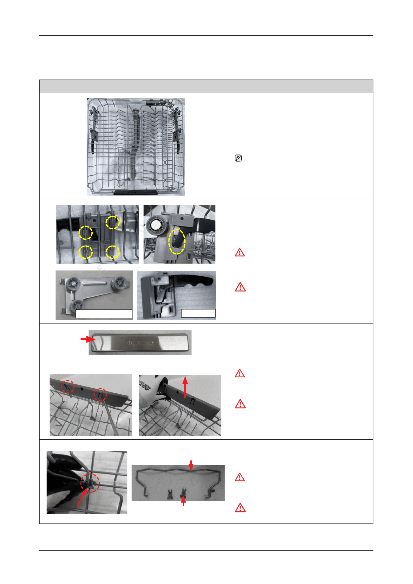
90 _ Disassembly and Reassembly
SAMSUNG PROPRIETARY. DO NOT COPY OR DISTRIBUTE WITHOUT PERMISSION
SAMSUNG PROPRIETARY. DO NOT COPY OR DISTRIBUTE WITHOUT PERMISSION
3-2-31. BASKET MIDDLE
Photo Description
[DISASSEMBLY]
1. Open the dishwasher’s DOOR, and take off the
BASKET MIDDLE.
NOTE :
Please refer to the section of ‘ASSY ROTOR MIDDLE’
for disassembly of rotor middle.
ASSY BRACKET ADJUSTER
ASSY Adjuster
2. Release 4 hooks of ASSY ADJUSTER (at each side) to
release them from the BASKET MIDDLE.
WARNING
Do not do this work without safety gloves.
It may cause injury from sharp edges.
CAUTION
Be careful not to break the hooks.
HANDLE BASKET
3. Remove the HANDLE BASKET by lifting the 2 ribs.
WARNING
Do not do this work without safety gloves.
It may cause injury from sharp edges.
CAUTION
Be careful not to brake the hooks.
WIRE FOLDING
HOLDER TINE-UP
4. Release the 2 HOLDER TINE-UP hooks and separate
the WIRE FOLDING from the BASKET MIDDLE.
WARNING
Do not do this work without safety gloves. I
t may cause injury from sharp edges.
CAUTION
Be careful not to brake the hooks.
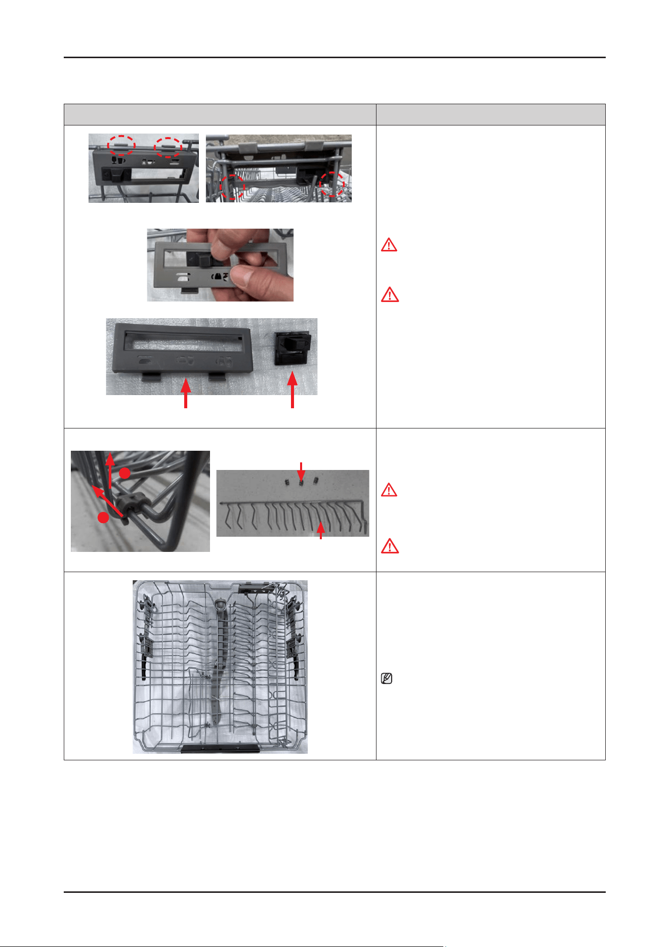
Disassembly and Reassembly _ 91
SAMSUNG PROPRIETARY. DO NOT COPY OR DISTRIBUTE WITHOUT PERMISSION
SAMSUNG PROPRIETARY. DO NOT COPY OR DISTRIBUTE WITHOUT PERMISSION
Photo Description
GUIDE BUTTONHOLDER GUIDE TINE
5. Release the 4 hooks of HOLDER GUIDE TINE and
separate it from the BASKET MIDDLE.
WARNING
Do not do this work without safety gloves. It may
cause injury from sharp edges.
CAUTION
Be careful not to break the hooks.
6.
Push the GUIDE BUTTON to separate it from the
HOLDER GUIDE TINE.
HOLDER GUIDE TINE-UP
WIRE GUIDE TINE
1
2
7. Release the hook of the HOLDER GUIDE TINE-UP
to separate the WIRE GUIDE TINE from the BASKET
MIDDLE.
WARNING
Do not do this work without safety gloves.
It may cause injury from sharp edges.
CAUTION
Be careful not to break the hooks.
[ASSEMBLY]
※ Reassembly is the reverse order of disassembly.
NOTE :
Carefully assemble the assembly position of the
HOLDER TINE-UP and the HOLDER GUIDE TINE-UP.
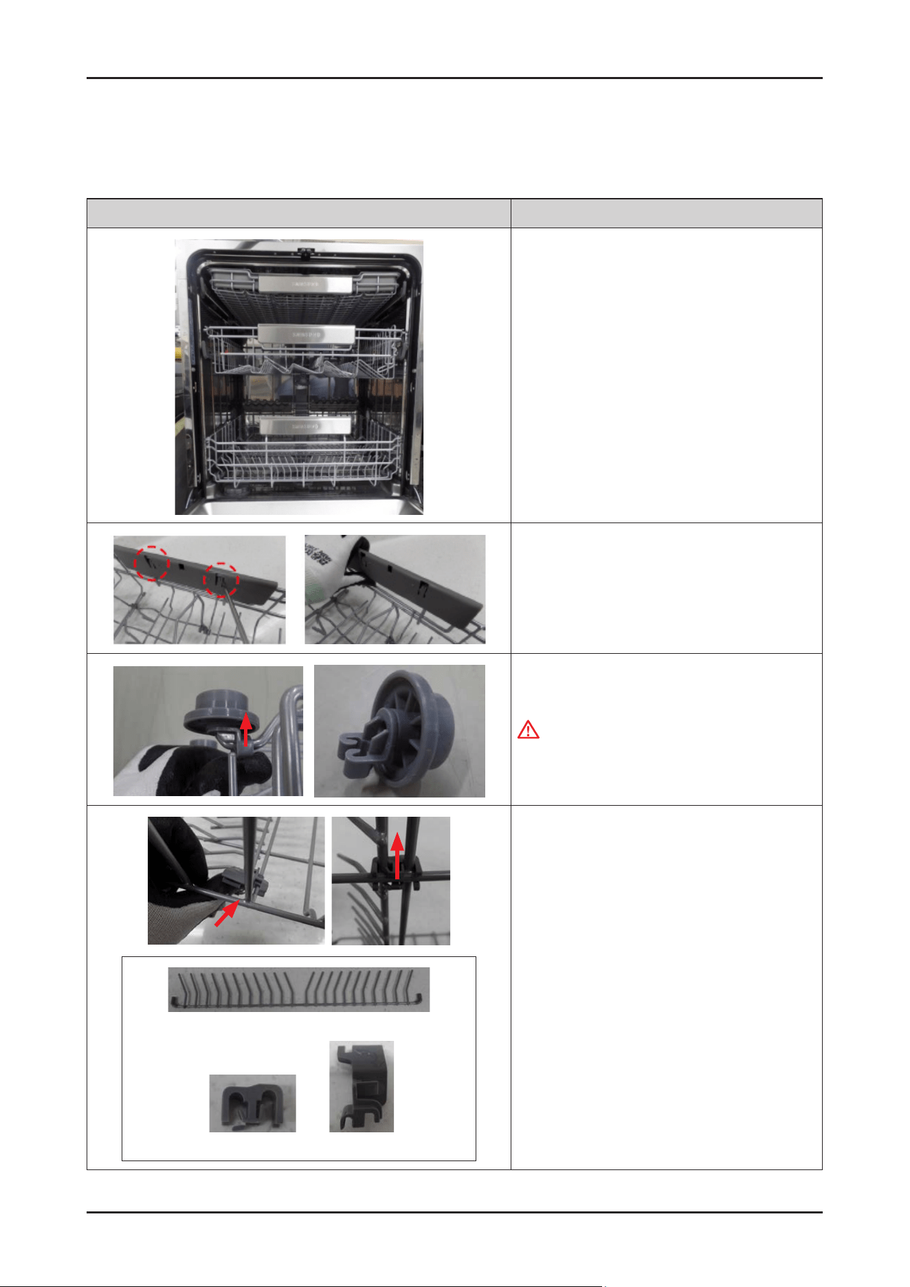
92 _ Disassembly and Reassembly
SAMSUNG PROPRIETARY. DO NOT COPY OR DISTRIBUTE WITHOUT PERMISSION
SAMSUNG PROPRIETARY. DO NOT COPY OR DISTRIBUTE WITHOUT PERMISSION
3-2-32. BASKET LOWER
- BASKET LOWER : DD82-01886B / SVC ASSY-BASKET LOWER
Photo Description
[DISASSEMBLY]
1. Open the dishwasher’s DOOR, and take off the
BASKET LOWER.
2. Remove the HANDLE BASKET by lifting the 2 ribs.
3. Release hooks to remove the ROLLER BASKET
WARNING
Do not do this work without safety gloves.
It may cause injury from sharp edges.
Wire tine
Holder tine low Holder wire L/R
4. Release the hook to remove the HOLDER WIRE L/R
and HOLDER TINE LOW, and separate the WIRE TINE.
[ASSEMBLY]
* Reassembly is the reverse order of disassembly.
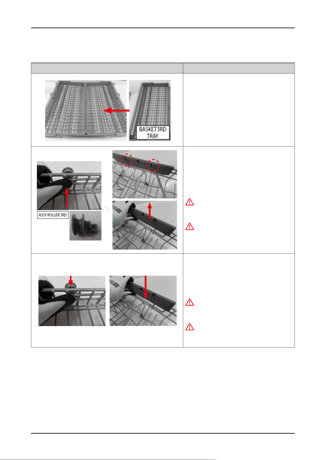
Disassembly and Reassembly _ 93
SAMSUNG PROPRIETARY. DO NOT COPY OR DISTRIBUTE WITHOUT PERMISSION
SAMSUNG PROPRIETARY. DO NOT COPY OR DISTRIBUTE WITHOUT PERMISSION
3-2-33. BASKET 3RD
Photo Description
[DISASSEMBLY]
1. Lift up the BASKET 3RD TRAY and separate it.
2. Release the hook of the ASSY ROLLER 3RD xed to
the WIRE FRAME 3RD and separate it.
3.
Remove the HANDLE BASKET by lifting the 2 ribs.
WARNING:
Do not do this work without safety gloves.
It may cause injury from sharp edges.
CAUTION
Be careful not to break the hooks.
[ASSEMBLY]
1. Assemble the BASKET 3RD with the ASSY ROLLER
3RD and the HANDLE BASKET together.
WARNING:
Do not do this work without safety gloves.
It may cause injury from sharp edges.
CAUTION
Be careful not to break the hooks.
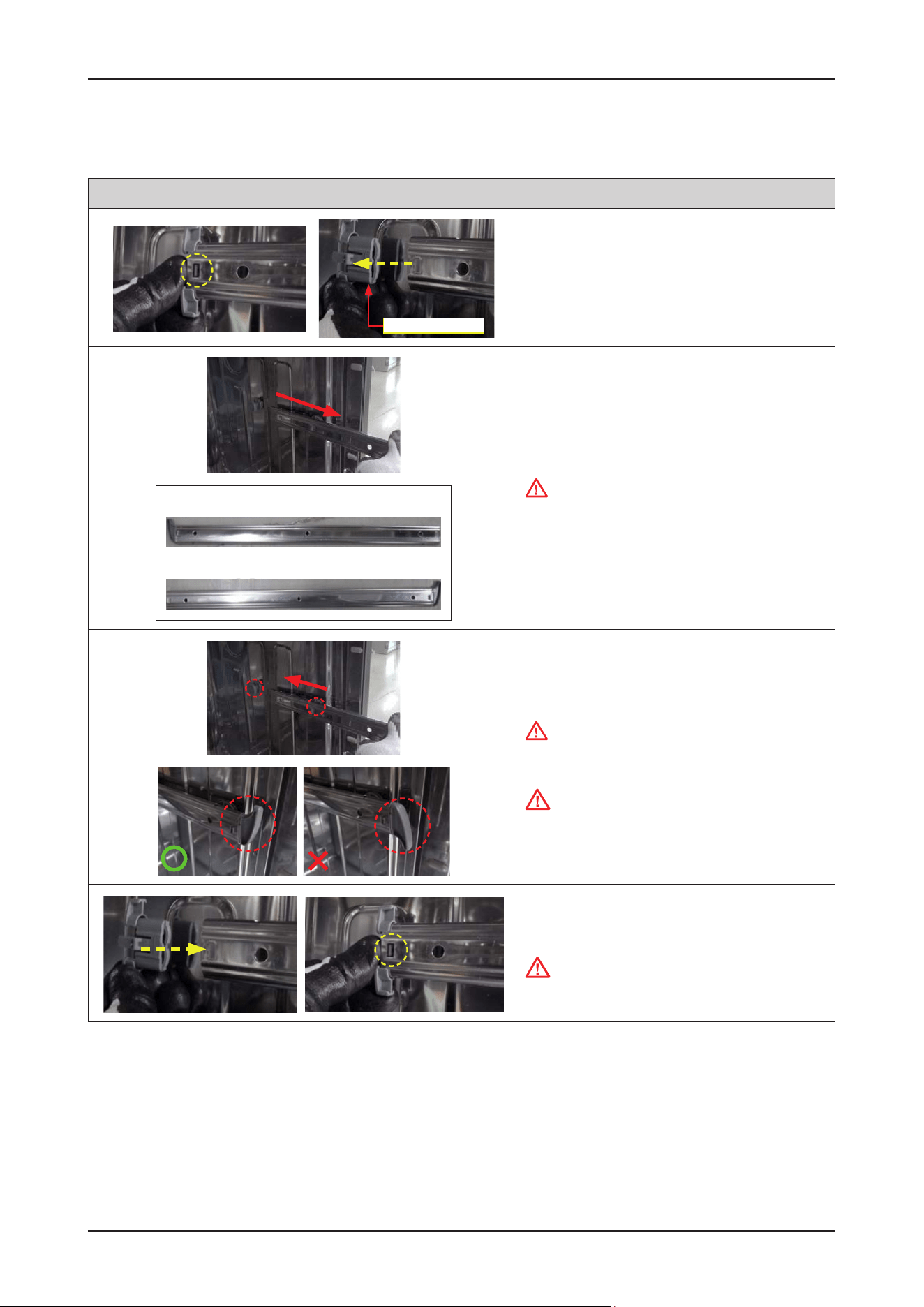
94 _ Disassembly and Reassembly
SAMSUNG PROPRIETARY. DO NOT COPY OR DISTRIBUTE WITHOUT PERMISSION
SAMSUNG PROPRIETARY. DO NOT COPY OR DISTRIBUTE WITHOUT PERMISSION
3-2-34. RAIL BASKET / HOLDER RAIL REAR
Photo Description
Holder Rail Rear
[DISASSEMBLY]
1.
Remove the HOLDER RAIL REAR by pulling back with
releasing the hook.
Rail Basket Right
Rail Basket Left
2. Remove the RAIL BASKET.
WARNING
Do not do this work without safety gloves.
It may cause injury from sharp edges.
[ASSEMBLY]
1.
Fit the RAIL BASKET on the ROLLER RAIL.
WARNING
Do not do this work without safety gloves.
It may cause injury from sharp edges.
CAUTION
Make sure of the direction of the RAIL BASKET when
it’s reassembled.
The front part of the RAIL BASKET faces upward.
2. Assemble the HOLDER RAIL REAR to the RAIL
BASKET.
CAUTION
Make sure to lock the hook to hole of RAIL BASKET.
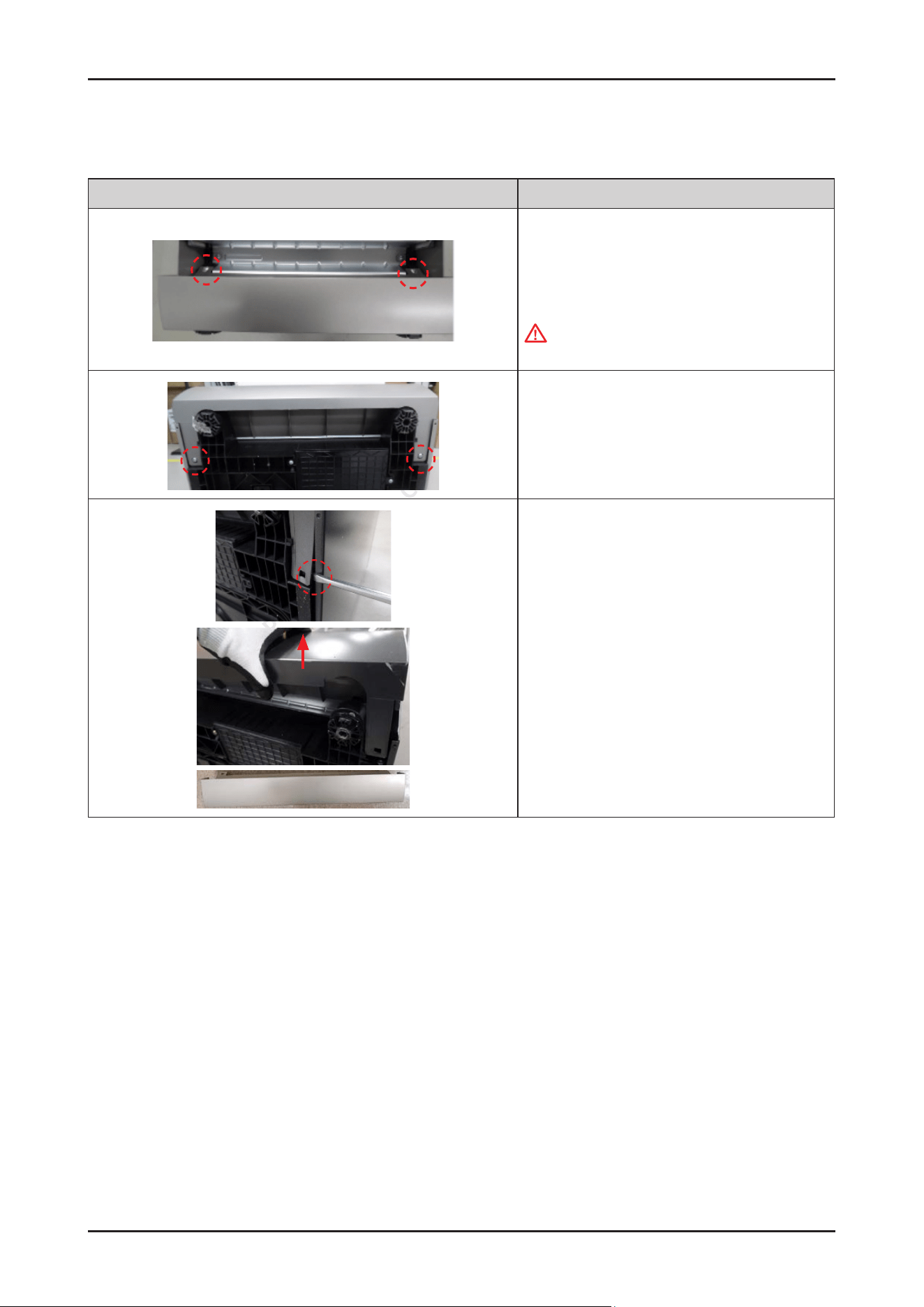
Disassembly and Reassembly _ 95
SAMSUNG PROPRIETARY. DO NOT COPY OR DISTRIBUTE WITHOUT PERMISSION
SAMSUNG PROPRIETARY. DO NOT COPY OR DISTRIBUTE WITHOUT PERMISSION
3-2-35. COVER PLINTH
Photo Description
[DISASSEMBLY]
1. Open the DOOR to 90˚, and release 2 screws.
- Screws: DD81-02694A / 2 pcs
WARNING
Be sure to remove the power plug before servicing.
2. Lay down the dishwasher on the back, and release 2
screws.
- Screws: DD81-02694A / 2 pcs
3. Release the holder of the COVER PLINTH slightly from
the hook with a at-head screw driver, and pull up the
COVER PLINTH.
4.
Do same work at the opposite side.
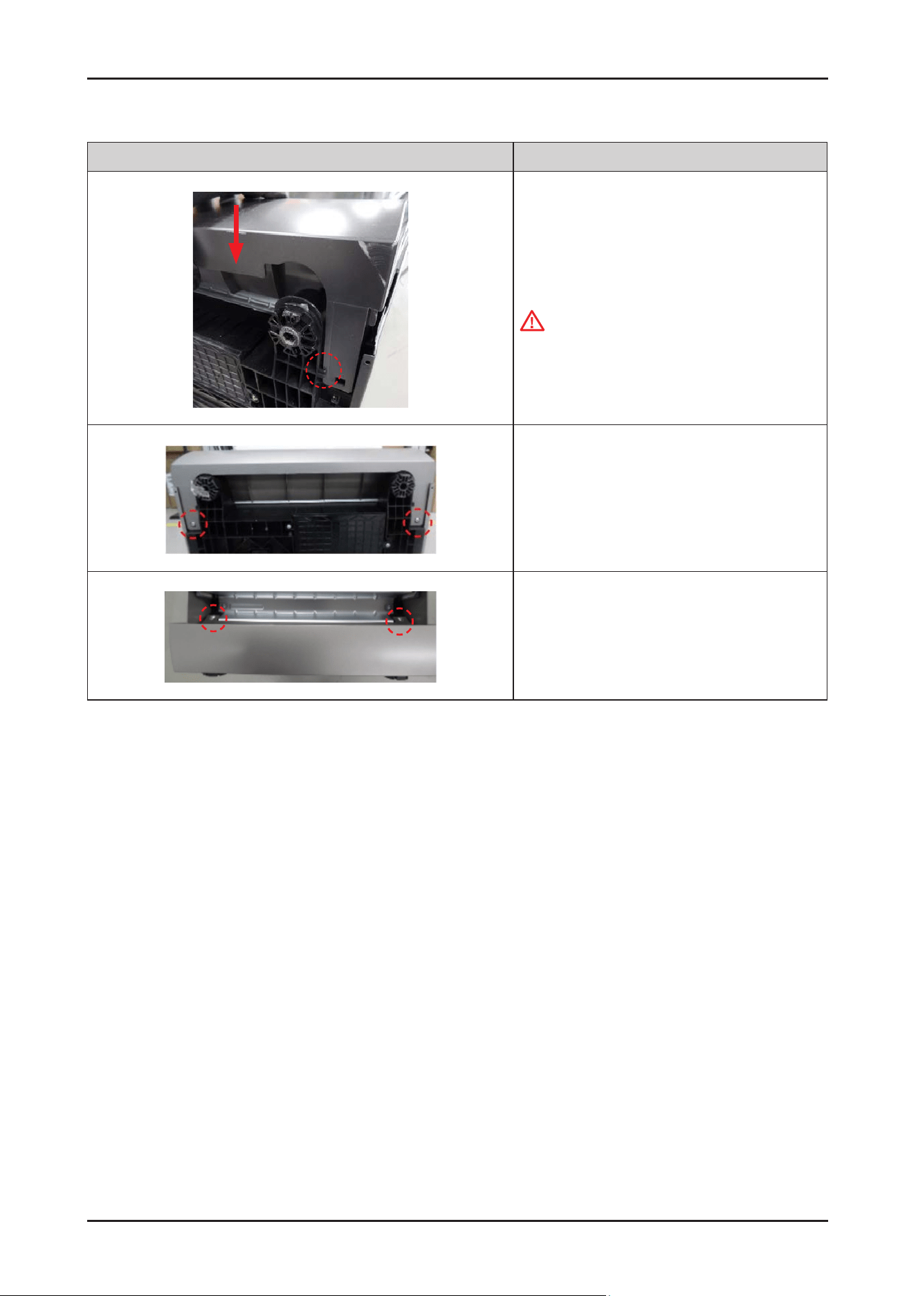
96 _ Disassembly and Reassembly
SAMSUNG PROPRIETARY. DO NOT COPY OR DISTRIBUTE WITHOUT PERMISSION
SAMSUNG PROPRIETARY. DO NOT COPY OR DISTRIBUTE WITHOUT PERMISSION
Photo Description
[ASSEMBLY]
1.
Assemble the COVER PLINTH to the BASE.
CAUTION
Insert the COVER PLINTH inside the holder.
2. Fasten the 2 screws under the COVER PLINTH.
-
Screws : DD81-02694A / 2 pcs
3. Open the DOOR to 90˚, Fasten the 2 screws.
-
Screws: DD81-02694A / 2 pcs
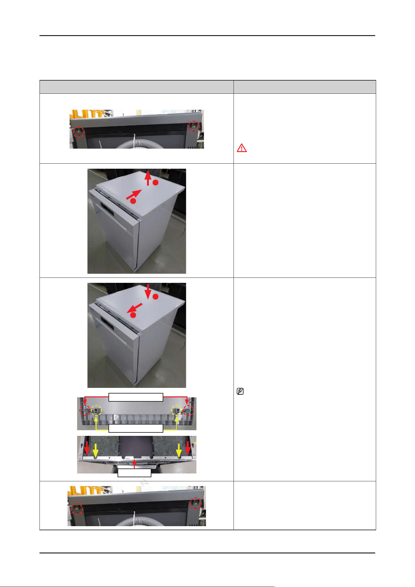
Disassembly and Reassembly _ 97
SAMSUNG PROPRIETARY. DO NOT COPY OR DISTRIBUTE WITHOUT PERMISSION
SAMSUNG PROPRIETARY. DO NOT COPY OR DISTRIBUTE WITHOUT PERMISSION
3-2-36. COVER TOP
Photo Description
[DISASSEMBLY]
1. Release the 2 screws.
- Screws: DD81-02692A / 2 pcs
WARNING
Be sure to remove the power plug before servicing.
1
2
2. Pull the COVER TOP backward to release hooks, and
take it off upward.
2
1
Hook Of Cover Top
Guide Of Cover Top
Tub Frame
[ASSEMBLY]
1.
Fit the COVER TOP on the top of dishwasher, and
push it forward to assembly.
NOTE :
Pay attention to lock the hooks (COVER TOP) to the
TUB FRAME.
2. Fasten the 2 screws.
-
Screws: DD81-02692A / 2 pcs
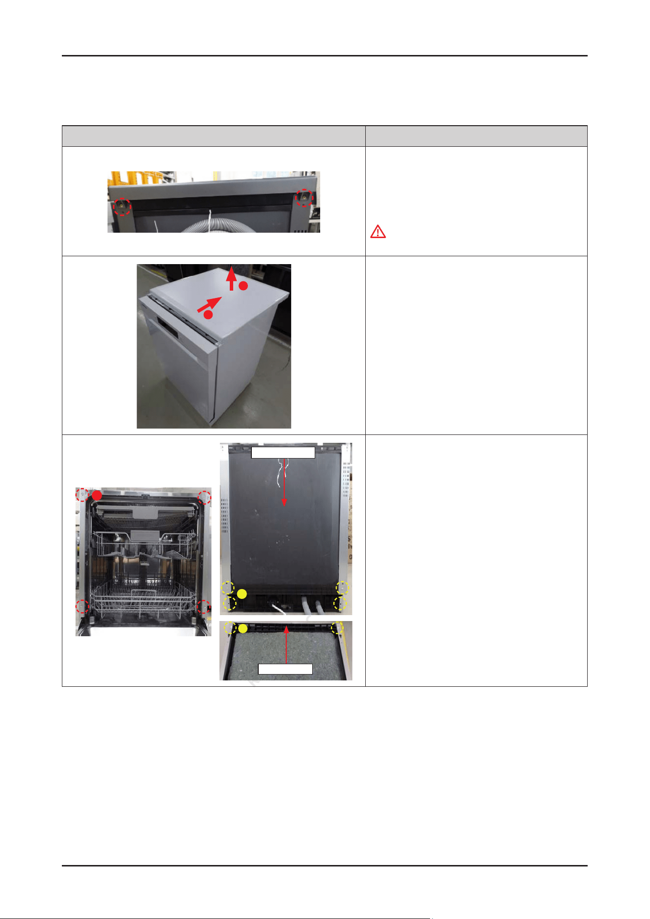
98 _ Disassembly and Reassembly
SAMSUNG PROPRIETARY. DO NOT COPY OR DISTRIBUTE WITHOUT PERMISSION
SAMSUNG PROPRIETARY. DO NOT COPY OR DISTRIBUTE WITHOUT PERMISSION
3-2-37. SIDE PANEL / GUIDE TUB TOP / COVER TUB REAR (DW70****F*)
Photo Description
[DISASSEMBLY]
1. Release the 2 screws.
-
Screws: DD81-02692A / 2 pcs
WARNING
Be sure to remove the power plug before servicing.
1
2
2. Pull the COVER TOP backward to release hooks, and
take it off upward.
A
B
Cover Tub Rear
B
Guide Tub Top
3. Release the screws.
•
Front side
- Type A: DD81-02693A / 4 pcs
•
Rear side
- Type B: DD81-02694A / 4 pcs
•
Top side
- Type B: DD81-02694A / 2 pcs
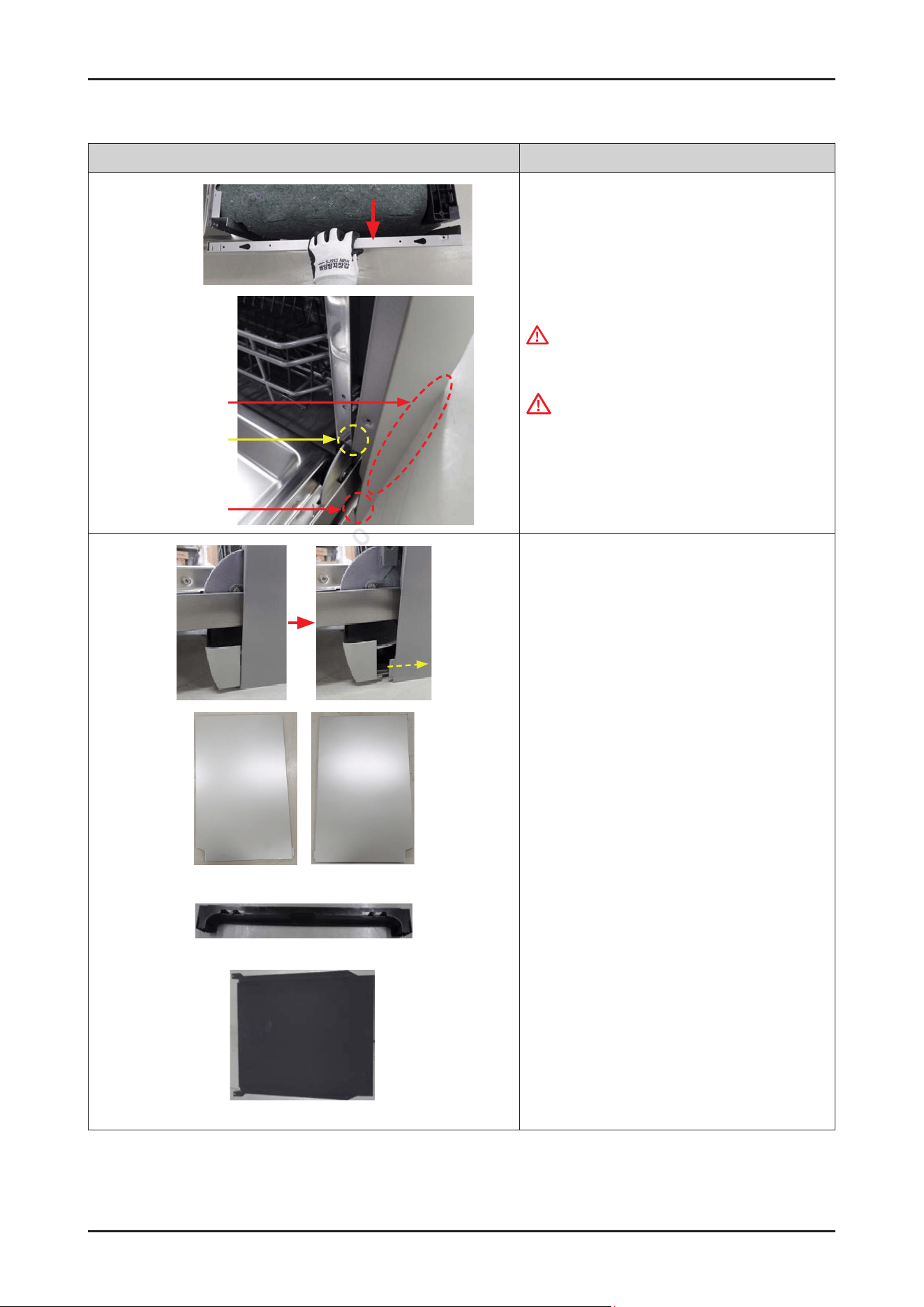
Disassembly and Reassembly _ 99
SAMSUNG PROPRIETARY. DO NOT COPY OR DISTRIBUTE WITHOUT PERMISSION
SAMSUNG PROPRIETARY. DO NOT COPY OR DISTRIBUTE WITHOUT PERMISSION
Photo Description
Not to get stuck
Could be dented
Hook
4. Take the SIDE PANEL off a little, just enough not to
get stuck to TUB FRAME.
WARNING
Do not do this work without safety gloves.
It may cause injury from sharp edges.
CAUTION
Be careful not to dent SIDE PANEL because of hook.
Side Panel Left Side Panel Right
Guide Tub Top
Cover Tub Rear
5. Pull the SIDE PANEL off from the COVER PLINTH.
GUIDE TUB TOP and COVER TUB REAR are
disassembled together.
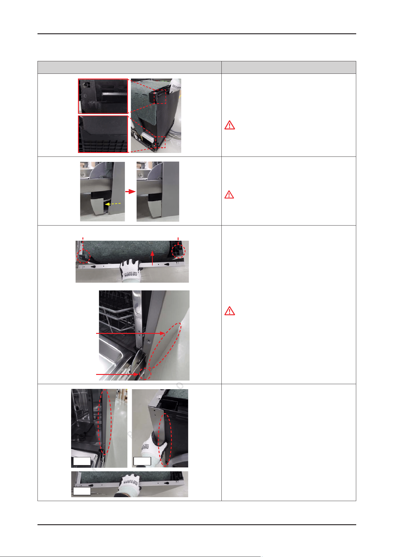
100 _ Disassembly and Reassembly
SAMSUNG PROPRIETARY. DO NOT COPY OR DISTRIBUTE WITHOUT PERMISSION
SAMSUNG PROPRIETARY. DO NOT COPY OR DISTRIBUTE WITHOUT PERMISSION
Photo Description
[ASSEMBLY]
1.
Assemble the GUIDE TUB TOP and the COVER TUB
REAR to the back of dishwasher.
CAUTION
They are not xed without the SIDE PANEL.
Recommend to work by 2 people.
2. Fit the hook of the SIDE PANEL into the COVER
PLINTH.
WARNING
Do not do this work without safety gloves.
It may cause injury from sharp edges.
On The Tub Frame
On The Guide Tub Top
Could be dented
Hook
3. Assemble the SIDE PANEL left & right to
each side.
CAUTION
Be careful not to dent SIDE PANEL because of hook.
Front
Top
Rear
4. Make sure to t the SIDE PANEL correctly.
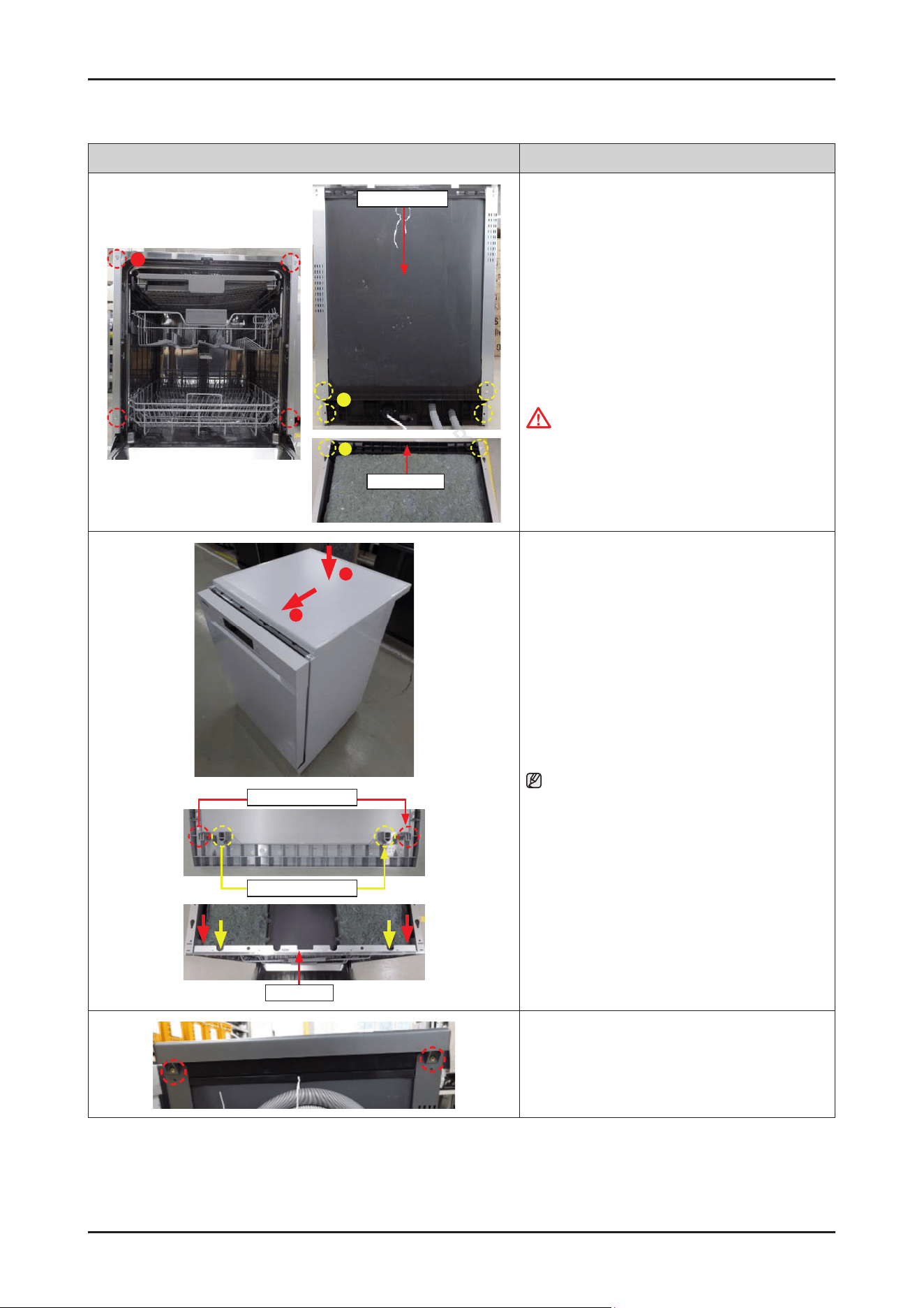
Disassembly and Reassembly _ 101
SAMSUNG PROPRIETARY. DO NOT COPY OR DISTRIBUTE WITHOUT PERMISSION
SAMSUNG PROPRIETARY. DO NOT COPY OR DISTRIBUTE WITHOUT PERMISSION
Photo Description
A
B
Cover Tub Rear
B
Guide Tub Top
5. Fasten the screws.
• Front side
-
Type A: DD81-02693A / 4 pcs
• Rear side
-
Type B: DD81-02694A / 4 pcs
• Top side
-
Type B: DD81-02694A / 2 pcs
CAUTION
Fasten the screws that was assembled to the origin
location. Don’t assemble to the wrong locations.
2
1
Guide Of Cover Top
Hook Of Cover Top
Tub Frame
6. Fit the COVER TOP on the top of dishwasher, and
push it forward to assembly.
NOTE :
Pay attention to lock the hooks(COVER TOP) to TUB
FRAME.
7. Fasten the 2 screws.
-
Screws: DD81-02692A / 2 pcs
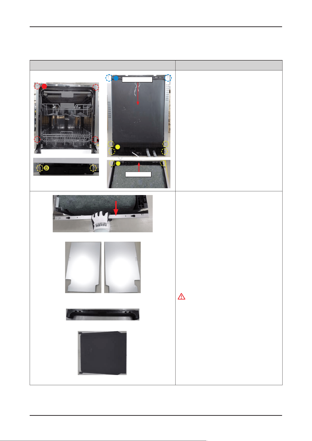
102 _ Disassembly and Reassembly
SAMSUNG PROPRIETARY. DO NOT COPY OR DISTRIBUTE WITHOUT PERMISSION
SAMSUNG PROPRIETARY. DO NOT COPY OR DISTRIBUTE WITHOUT PERMISSION
3-2-38. SIDE PANEL / GUIDE TUB TOP / COVER TUB REAR (EXCEPT DW70****F*)
Photo Description
B
C
Cover Tub Rear
B
Guide Tub Top
A
[DISASSEMBLY]
1.
Release the screws.
•
Front side (Type A): DD81-02693A / 4 pcs
(Type B): DD81-02694A / 2 pcs
•
Rear side (Type B): DD81-02694A / 4 pcs
(Type C): DD81-02692A / 2 pcs
•
Top side (Type B): DD81-02694A / 2 pcs
Guide Tub Top
Cover Tub Rear
Side Panel Left Side Panel Right
2. Disassemble the SIDE PANEL left & right from each
side.
GUIDE TUB TOP and COVER TUB REAR are
disassembled together.
WARNING
Do not do this work without safety gloves.
It may cause injury from sharp edges
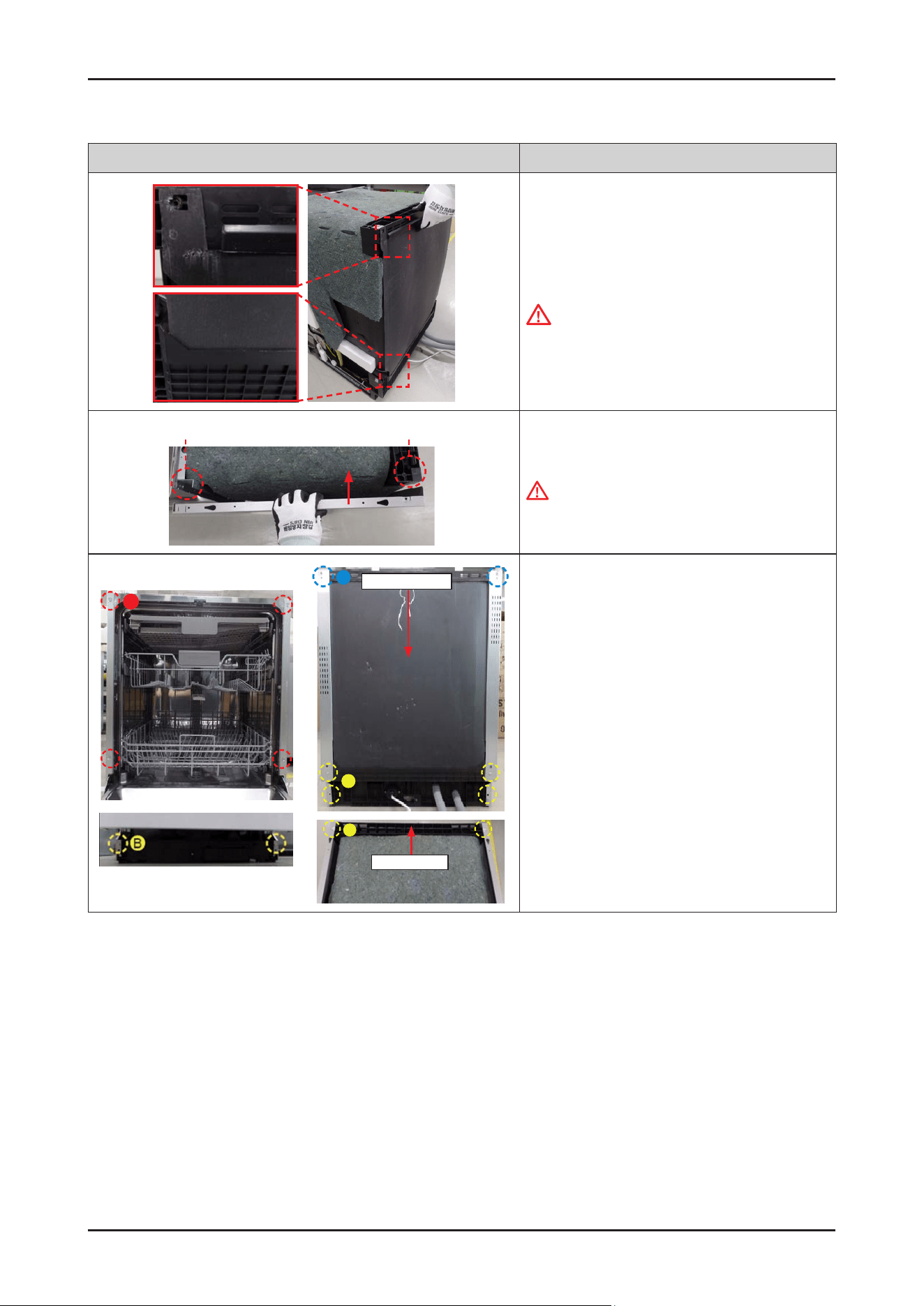
Disassembly and Reassembly _ 103
SAMSUNG PROPRIETARY. DO NOT COPY OR DISTRIBUTE WITHOUT PERMISSION
SAMSUNG PROPRIETARY. DO NOT COPY OR DISTRIBUTE WITHOUT PERMISSION
Photo Description
[ASSEMBLY]
1.
Assemble the GUIDE TUB TOP and the COVER TUB
REAR to the back of dishwasher.
CAUTION
They are not xed without the SIDE PANEL.
Recommend to work by 2 people.
On The Tub Frame
On The Guide Tub Top
2. Assemble the SIDE PANEL left & right to
each side.
WARNING
Do not do this work without safety gloves.
It may cause injury from sharp edges.
B
C
Cover Tub Rear
B
Guide Tub Top
A
3. Fasten the screws.
•
Front side (Type A): DD81-02693A / 4 pcs
(Type B): DD81-02694A / 2 pcs
•
Rear side (Type B): DD81-02694A / 4 pcs
(Type C): DD81-02692A / 2 pcs
•
Top side (Type B): DD81-02694A / 2 pcs
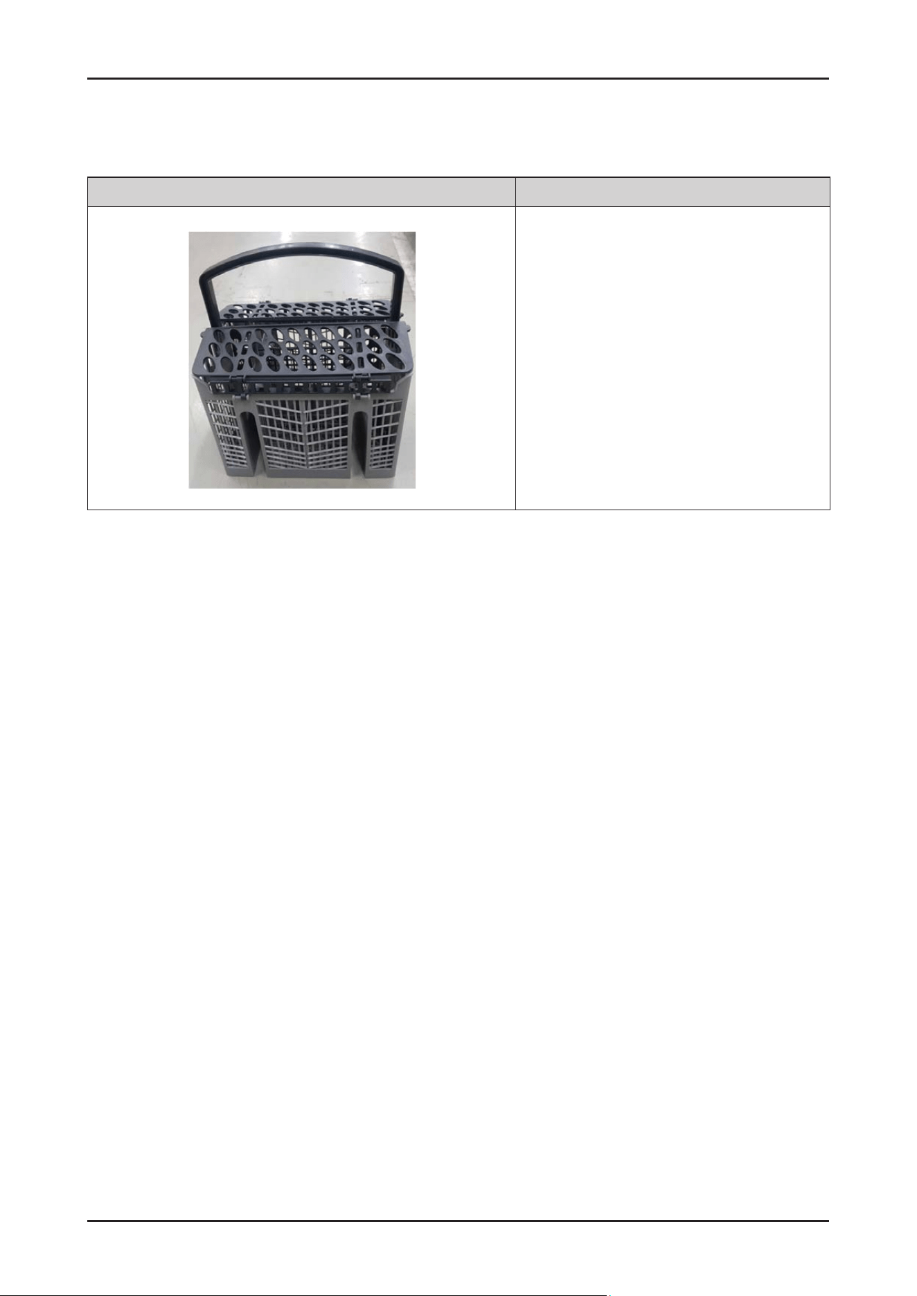
104 _ Disassembly and Reassembly
SAMSUNG PROPRIETARY. DO NOT COPY OR DISTRIBUTE WITHOUT PERMISSION
SAMSUNG PROPRIETARY. DO NOT COPY OR DISTRIBUTE WITHOUT PERMISSION
3-2-39. BASKET CUTLERY
Photo Description
[DISASSEMBLY/ASSEMBLY]
* This part will be serviced by assembly part only.

Disassembly and Reassembly _ 105
SAMSUNG PROPRIETARY. DO NOT COPY OR DISTRIBUTE WITHOUT PERMISSION
SAMSUNG PROPRIETARY. DO NOT COPY OR DISTRIBUTE WITHOUT PERMISSION
3-3. CHECKPOINTS AFTER FINISHING A SERVICE
1. Check the safety device
Check the operation of the door lock switch. Make sure that it is locked while the dishwasher is running and that it is
unlocked when the dishwasher stops.
2. Use authenticated parts only
If any part is not authenticated, replace it with an authenticated part.
3. Handling wires
Check if any wires are loose or too tight, if they are connected correctly, if they are well bound with tape,
and if they are properly clamped.
4. The state of screws and nuts
Check if the screws and nuts are fastened correctly. Check whether they are fastened with the specied torque.
5. Remove foreign material
Check whether any foreign material such as soil, wire scraps and screws are in the dishwasher.
(Check whether any foreign material is entering through the sump into the disposer.)
6. Check for water leakage
Check whether there is water leakage from the hose connector, door, case sump (drain motor, circulation motor, heater,
thermistor, distributor motor), and the water supply/drain hoses.
7 Check the power cable
Check if there is any damage to the power cable or power outlet. Check that the power capacity is appropriate.
8. Check leveling
Check whether the dishwasher is level.
9. Check the installation location
Check whether the installation location is at and stable.
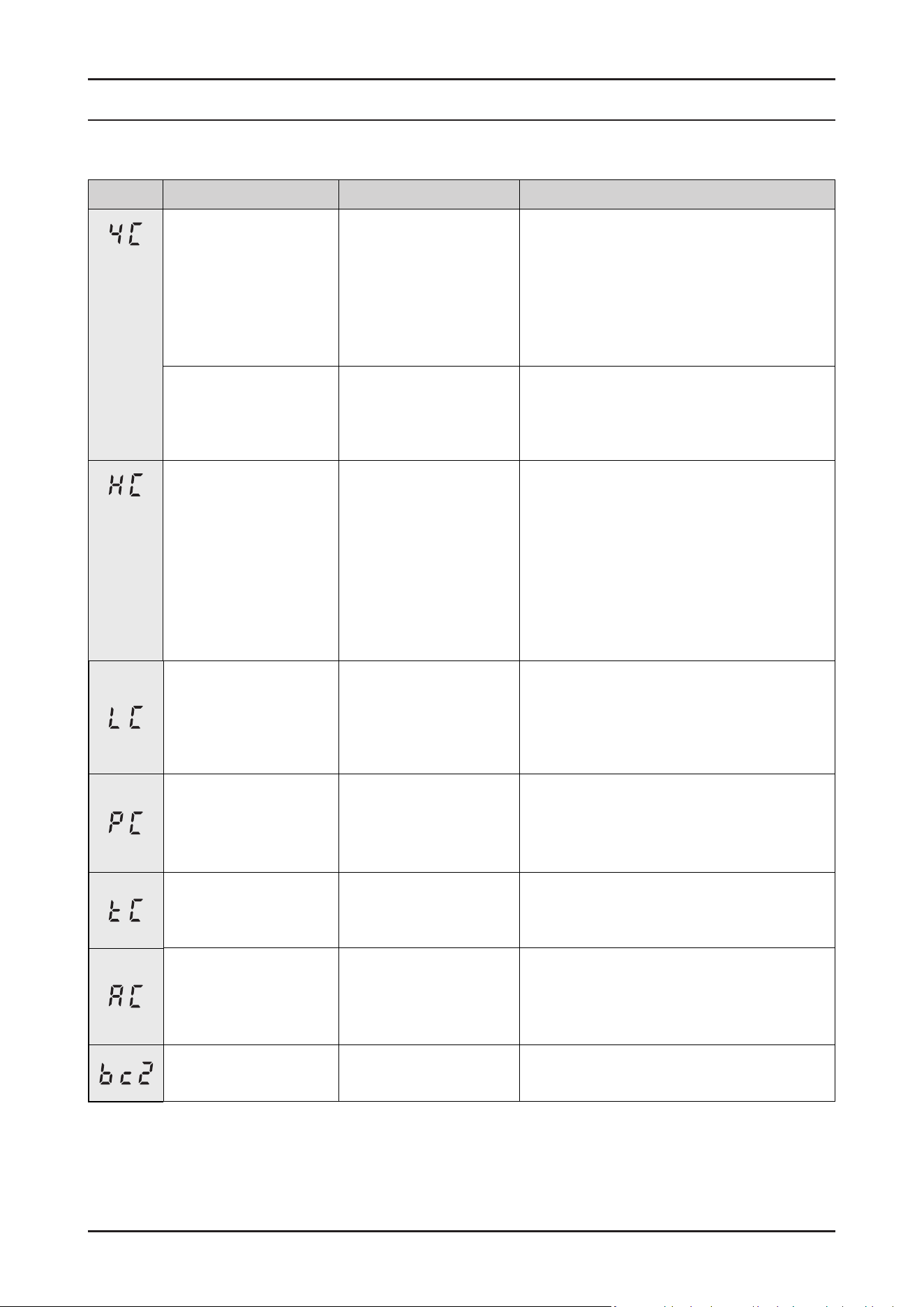
SAMSUNG PROPRIETARY. DO NOT COPY OR DISTRIBUTE WITHOUT PERMISSION
SAMSUNG PROPRIETARY. DO NOT COPY OR DISTRIBUTE WITHOUT PERMISSION
This Document can not be used without Samsung’s authorization.
4. TROUBLESHOOTING
4-1. Information Codes
Codes When occur Symptom Possible Causes
Flow-meter in Case
Brake don't detect proper
pulse counts in water
lling period.
In water-ll period,
it can't detect proper
ow-meter pulse counts
for 4 minute.
1.
Open water valve and make sure there are
not restrictions.
2.
Water pressure is too low.
3.
Water valve or Flow-meter is not working.
4.
Drain pump in not working.
(Water pressure switch detect high level.
So, cannot ll any more water)
During other steps, the
quantity of water is over
2L which is measured by
ow-meter.
Except water-ll period,
it detect ow-meter pulse
counts over 2 liter.
Water inlet valve is breakdown.
(Ex. Foreign substance block the valve closing.)
In any mode, Heater is
not working.
In Heater operation step.
-
Does not reach
required temperature
within 60 minutes.
1.
Heater on temperature sensor is broken.
2.
Water in Tub is too low during Heater
operation.
3.
Low water level protect device is not
working.
4.
Low water level detecting switch is broken.
5.
Washing motor is broken.
6.
No water in Tub.
7.
Not using the specied detergent.
During power on, the
leakage sensor switch is
kept on for 2 seconds.
(Has priority over other
errors.)
Micro switch in leakage
sensor was closed by
oating Styrofoam.
1.
Dishwasher tub was overlled.
2.
Water from a leak went to bottom tray.
Distribution motor is not
working.
In the washing stage,
it cannot change the
channel to each rotor
1.
Distribution motor is broken.
2.
Main PBA is broken.
3.
Micro Switch (to check the location of
distribution motor) is broken.
In any mode, short/open
circuit of thermistor is
detected.
Short/open circuit or defective temperature
sensor.
In any mode,
PCB communication is
not working.
Keep going remained
cycle.
1.
The main PBA or sub PBA is out of order.
2.
The communications connection for the
main PBA or sub PBA is not properly
connected.
Key has been pressed
for 30s
Key has been pressed.
106 _ Troubleshooting
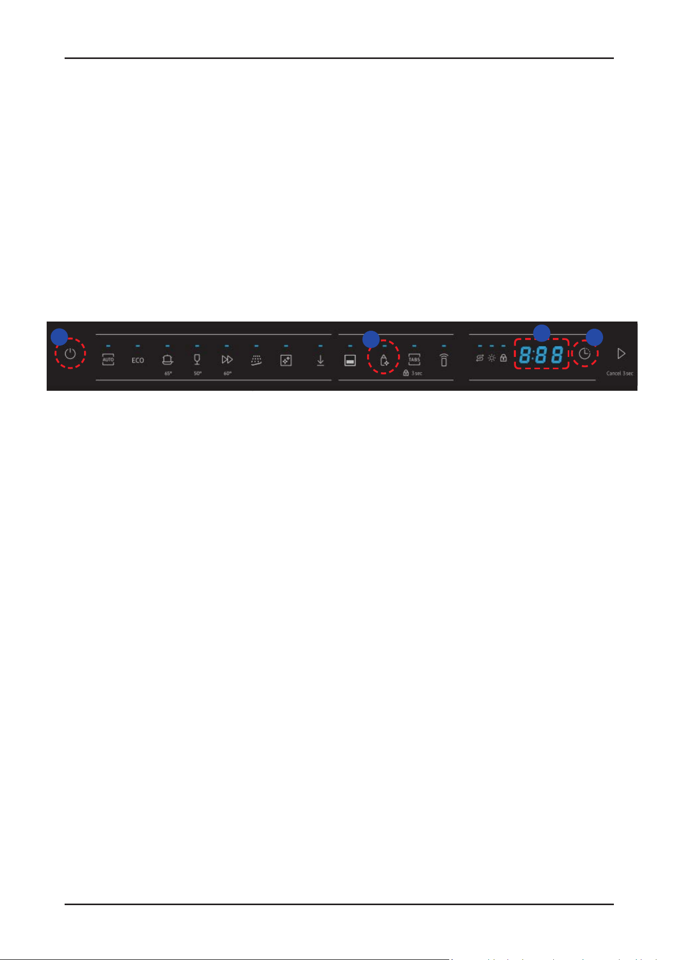
SAMSUNG PROPRIETARY. DO NOT COPY OR DISTRIBUTE WITHOUT PERMISSION
SAMSUNG PROPRIETARY. DO NOT COPY OR DISTRIBUTE WITHOUT PERMISSION
This Document can not be used without Samsung’s authorization.
4-2. SVC Test Mode
1. Entrance method
① Power on → ② Set delay time to '17h' → ③ Hold down the 'Sanitize' key for 7seconds →
④ Enter SVC test mode with displayed ‘AS’
* When entering test mode, ‘AS → b0 → F*(Main PBA) → b1 → F*(Sub PBA) → AS → …’ will be displayed on the screen.
(‘F*’ means the version of Software)
1
3
4
2
Troubleshooting _ 107
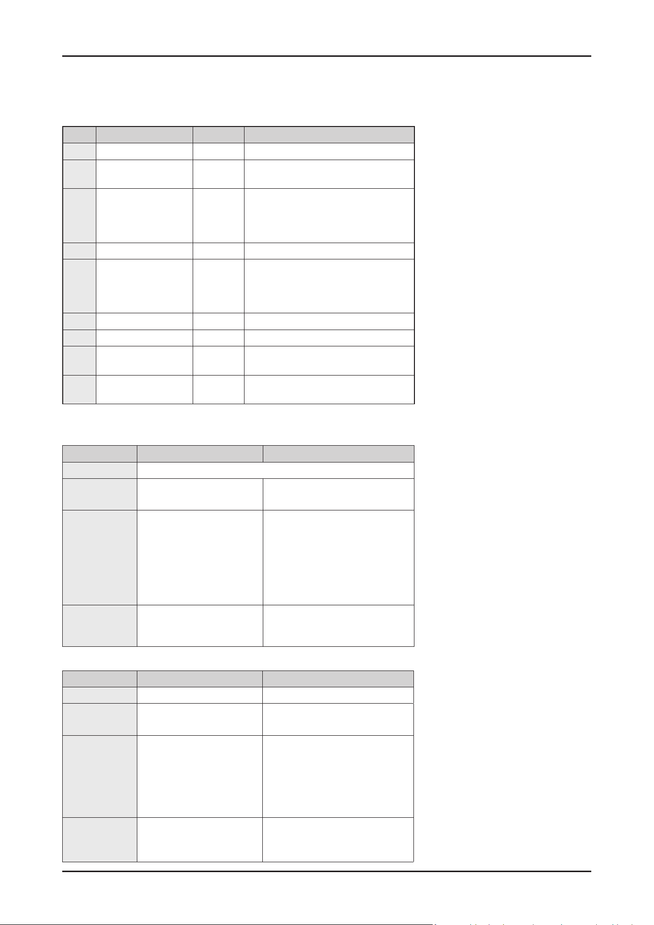
SAMSUNG PROPRIETARY. DO NOT COPY OR DISTRIBUTE WITHOUT PERMISSION
SAMSUNG PROPRIETARY. DO NOT COPY OR DISTRIBUTE WITHOUT PERMISSION
This Document can not be used without Samsung’s authorization.
Step Load Display State
1 Drain pump 01
Operating for 30 s
2 Water inlet valve 02
Turn on the water inlet valve.
3L water enter by the ow-meter.
3 Circulation pump
(Low speed)
Distribution motor
Heater
03
See details about Test Mode Step3*
4 Dispenser 04
Work according to default setting
5 Circulation pump
(High speed)
Distribution motor
Heater
05 /
Temperature
See details about Test Mode Step5**
6 Regeneration Valve 06
Open the regeneration valve for 30s.
7 Drain pump 07
Operating for 30s
8 Auto Door open 08
Turn on Auto-open door actuator for 30s.
If the door is not opened, retry 60 s again.
9 Clean EEPROM &
Complete
00
Restore default settings, Finish SVC test
mode
Step 3 Auto Mode Manual Mode
Target Temp. Raise up as 2℃
After meeting
Target Temp.
Go to the next step Keep operating Circulation pump
with Heater-off.
Time to operate
Circulation
pump
Following condition to meet
the rst of below 2 condi-
tions.
- Operating Circulation
pump for 90 s.
- To meet the target tem-
perature(2℃).
Pump will operate for 3 hours from
the start of operating.
After passed 3 hours, just stop
all operation with displaying the
current step.(03)
Operation of
Distribution
motor
Change automatically
- TOP/MID(30 s) → LOW(30 s)
It can be selected the location of
distribution motor by ‘Multi tab’ key
Step 5 Auto Mode Manual Mode
Target Temp. Raise up as 3℃ Raise up to 69℃
After meeting
Target Temp.
Go to the next step Keep operating Circulation pump
with Heater-off
Time to operate
Circulation
pump
Following condition to meet
the rst of below 2 conditions.
- Operating Circulation
pump for 300 s.
- To meet the target tem-
perature(3℃).
Pump will operate for 3 hours from
the start of operating.
After passed 3 hours, just stop
all operation with displaying the
number of step.(05)
Operation of
Distribution
motor
Change automatically.
- TOP/MID(100 s) →
LOW(100 s) → …
It can be selected the location of
distribution motor by ‘Multi tab’
key.
2. Mode Operation
* Details about Step 3
** Details about Step 5
- In Auto mode(‘AS’), all steps will be
executed step by step after pressing
the “start” button.
- In case of opening the door, it will stop
operation with displayed ‘dC’.
If close the door, ‘dC’ will be released
and keep operate current step.
- Before starting Auto mode (‘AS’), you
can press ‘Auto’ key to Manual (Step
1~Step 9) mode in which specic step
will be selected when pressed ‘Auto’
key each time.
• After choosing the maximum step
number(’09’), it will be changed to
Auto mode(‘AS’) again.
※ AS → 01 → 02 → … → 09 → AS → 01 → …
- When selected each step of Manual
mode, it will be operated after
pressing the ‘Start’ button.
In case of opening the door, it will be
displayed ‘dC’. If close the door,
‘dC’ will be released and current step
will be operated.
108 _ Troubleshooting
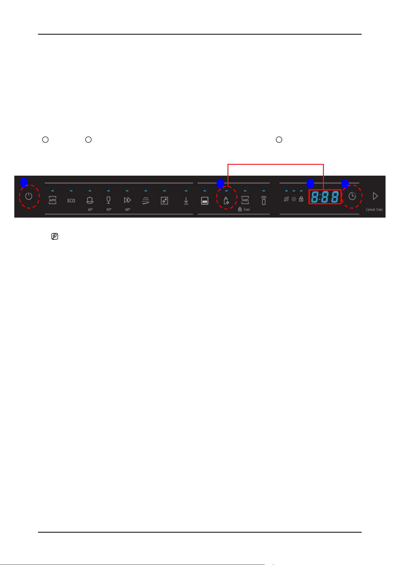
SAMSUNG PROPRIETARY. DO NOT COPY OR DISTRIBUTE WITHOUT PERMISSION
SAMSUNG PROPRIETARY. DO NOT COPY OR DISTRIBUTE WITHOUT PERMISSION
This Document can not be used without Samsung’s authorization.
4-3. Information How To Access Data Records
You can use this mode when you want to know which information code was occurred at the dishwasher recently.
1. Entrance method
1
Power on →
2
Hold down ‘Sanitize’ and ‘Delay Start‘ key together for 7 seconds →
3
Check the information code
1
2
3
2
For 7 seconds
NOTE :
- Only 1 information code would be recorded that was occurred at the most recently.
- You can press any key to release this mode.
- Recorded code will be cleared after running the SVC test mode(Step 9, Clean EEP ROM).
Troubleshooting _ 109
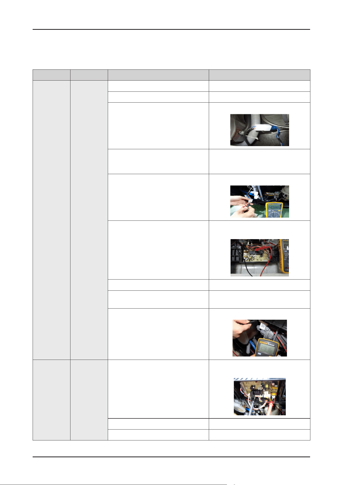
SAMSUNG PROPRIETARY. DO NOT COPY OR DISTRIBUTE WITHOUT PERMISSION
SAMSUNG PROPRIETARY. DO NOT COPY OR DISTRIBUTE WITHOUT PERMISSION
This Document can not be used without Samsung’s authorization.
Error type Error mode Checking method Corrective actions
Inlet
water error
Malfunction1
(4C)
Check whether the water tap is open. Open the water tap.
Check whether the pipe bending. Put the water pipe at the right place.
Check the connection for the Aqua Stop
connector.
Reconnect the Aqua Stop Connector.
Check whether the low water pressure Make sure the water pressure is ≥0.04MPa
Use dishwasher when there’s not much
water used at other place
Check whether the coil in Aqua Stop is
conductive.
(Remove the connector before measuring.)
- Normal Approx:4.08Kohm
- Faulty : Replace the Aqua Stop
Check whether the Aqua Stop is operating
normally in the Main PBA
Check the voltage between the blue wire of
the Main PBA EV1 connector and the blue
wire of the ACN
- 230V(while operating)
- Faulty: replace the main PBA assy.
- Normal : Replace the Aqua Stop
Wiring malfunction or damage Maintenance
Pressure switch malfunction.
Check the pressure switch
- Faulty: replace the pressure switch
Check whether the Drain pump coil is
conductive(remove the connector before
measuring.
- Normal Approx:285 ±10%ohm
(Hanyu Drain pump)
- Faulty: replace the Drain pump
Inlet
water error
Malfunction1
(4 C)
Check the operation of the Drain pump relay
Check the operating voltage between the
red wire of the Main PBA PS connector and
the blue wire of the ACN connector.
- 230V(while operating)
- Faulty: Replace the Main PBA assy.
- Normal: Replace the Drain pump.
Drain hose is blocked or damaged Replace it
Wiring malfunction or damage Maintenance
4-4. Malfunction Table
110 _ Troubleshooting
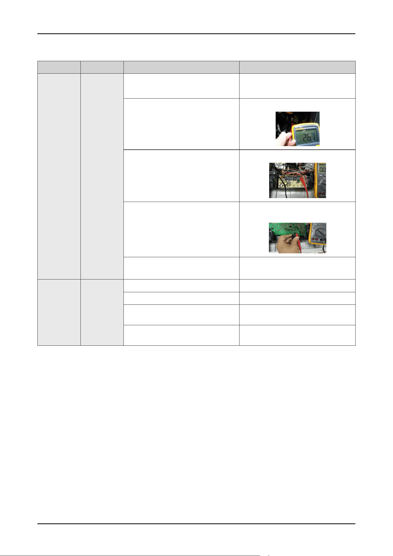
SAMSUNG PROPRIETARY. DO NOT COPY OR DISTRIBUTE WITHOUT PERMISSION
SAMSUNG PROPRIETARY. DO NOT COPY OR DISTRIBUTE WITHOUT PERMISSION
This Document can not be used without Samsung’s authorization.
Error type Error mode Checking method Corrective actions
Heater error
Malfunction2
(HC)
Check the connections of the heater
connectors
Reconnect the heater connector
Check the resistance between both ends of
the heater terminal
-
Approx:29 ohm
- Faulty: replace the heater
Check the connections of the heater Relay
Check the voltage between the pink wire of
the main HEAT and the blue wire of the ACN
terminal
-
230V(while operating)
Reconnect the heater relay connectors
Check the driving signals for the heater relay
Measure the voltage between
- When the heater is off:12V
- When the heater is operating:0V
- Faulty: replace the Main PBA assy.
- Normal: replace the heater relay.
Check the operation of the thermistor
check whether occur the “tC" error.
See the Malfunction tC
Pressure
Switch
malfunction.
Do not work
when heating
Malfunction2
(HC)
Check whether Motor low speed or stops to spin
Replace the motor
Check whether The lter is blocked Clean the lter
Check whether The water level in the tub is
not high enough
Check the pressure sensor, inlet valve,
ow-meter or the height of the drain pipe.
Check whether heater damage, or wiring is
loosen
Replace heater or check the wiring
Troubleshooting _ 111

SAMSUNG PROPRIETARY. DO NOT COPY OR DISTRIBUTE WITHOUT PERMISSION
SAMSUNG PROPRIETARY. DO NOT COPY OR DISTRIBUTE WITHOUT PERMISSION
This Document can not be used without Samsung’s authorization.
Error type Error mode Checking method Corrective actions
Leakage error
Malfunction3
(LC)
Check whether the ow-meter terminal
failure
Repair the ow-meter terminal.
Check the connections for the leakage switch
connector
Reconnect the leakage switch connector
Check whether the Aqua Stop operates
normally.
See “Malfunction1(4C)”.
Check whether the drain pump operates
normally.
Replace the drain pump
Check whether water is supplied (even small
amounts) in the intervals when the Electric
supply hose is operating
Remove foreign material form the Aqua Stop.
If you cannot remove the foreign material
form the Aqua Stop, replace it
Check whether there is any trace of water
leakage on the top of the case leakage switch
Clean the leakage switch
The oat too high or something make the
micro switch set
Repair the oat and leakage switch
Drain hose is obstructed or snap Put the hose in the right way
Base buoy damage or is too dirty Replace or clean the base buoy
The wiring be wrong connected with the micro
switch after repair
Right connected with the leakage switch
Diverter valve
Error
PC
Run service diagnostic cycle, the digial display
"3" ,check the voltage between RY8 port of
CN2 and N port in the main PCBA.
1. If there is not voltage output ,change relay
RY8 or main PCBA.
2 If there is about 220V, then check if the
ALT valve can act , if it can’t run, change
the valve.
112 _ Troubleshooting
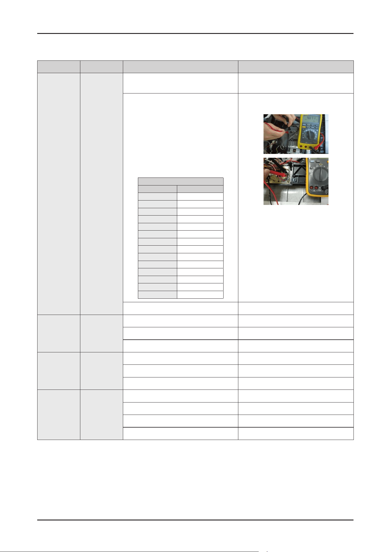
SAMSUNG PROPRIETARY. DO NOT COPY OR DISTRIBUTE WITHOUT PERMISSION
SAMSUNG PROPRIETARY. DO NOT COPY OR DISTRIBUTE WITHOUT PERMISSION
This Document can not be used without Samsung’s authorization.
Error type Error mode Checking method Corrective actions
Thermistor
error
Malfunction4
(tC)
Check whether connections for the
thermistor connector
Reconnect the thermistor connector
Check whether the thermistor is operating
normally. Measure the voltage between
both ends of the thermistor
(the RE connector of main PBA)
- 0.06V---4.8V
Measure the resistance between both ends
of the thermistor.
Remove the connector before measuring
(see the table right)
Thermistor table
Temp(℃) Resistance(KΩ)
5 22.27
10 18.07
15 14.75
20 12.11
25 10
30 8.302
35 6.928
40 5.810
45 4.897
50 4.145
55 3.525
60 3.011
65 2.582
70 2.223
- Faulty: replace the thermistor
- Normal replace the main PBA assy.
Wiring malfunction or damage Replace it
Dishwasher do
not work after
closing door
None
The door is not close properly Close the door properly
Door switch malfunction or damage Replace the door switch
Wiring malfunction or damage maintenance
The motor
sounds but
can not
operate or spin
None
Motor bearing malfunction Replace the motor
The Starting capacitor malfunction Replace the capacitor
Voltage is not suitable for the motor Change to the correct voltage
The motor
overheating
None
Short circuit failure of the motor coil Replace the motor
Voltage is not suitable Change to the correct voltage
The Starting capacitor malfunction Replace it
Motor axis is stick Clean the axis or replace it.
Troubleshooting _ 113
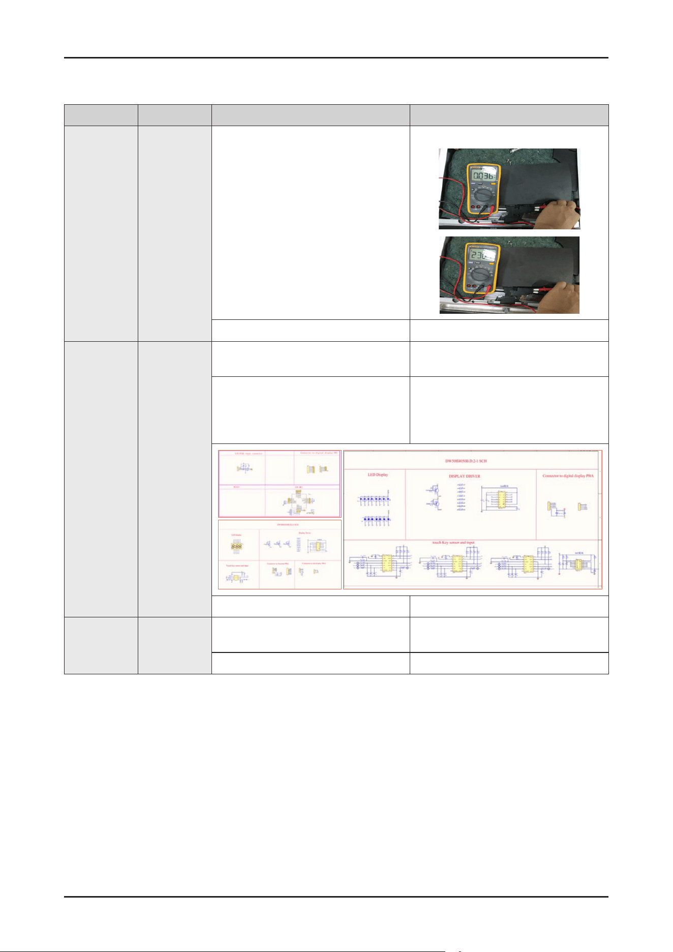
SAMSUNG PROPRIETARY. DO NOT COPY OR DISTRIBUTE WITHOUT PERMISSION
SAMSUNG PROPRIETARY. DO NOT COPY OR DISTRIBUTE WITHOUT PERMISSION
This Document can not be used without Samsung’s authorization.
Error type Error mode Checking method Corrective actions
The
dishwasher
works when
the door is
open
None
Door switch malfunction or damage Check
the micro switch when turning the micro
switch on and off.
Check the conduction between the pink
wire and the pink wire.
Check the conduction between the bule
wire and gray wire
- Micro switch on : 0
- Micro switch off : 230V
Replace the door switch.
Wiring malfunction or damage Replace the latch.
Display error None
1. Check the connector for the Display LED
connector part.
- Reconnect the connectors for Display
LED
2. Check the Display LED Connect the
SCAN1 SCAN0 COM4 COM5 COM6 to
+5v and connect the Q0-Q7 to GND.
- Nomal : The Display LED should all light up.
- Faulty: Replace the Display LED
3. Check the DC voltage of the Main PBA - See the "Main PBA DC voltage error"
Key input error None
1. Check the connections for the Sub PBA
connector part.
- Reconnect the Sub PBA connectors.
2. Check the DC voltage of the Main PBA - See "Main PBA DC voltage error".
114 _ Troubleshooting
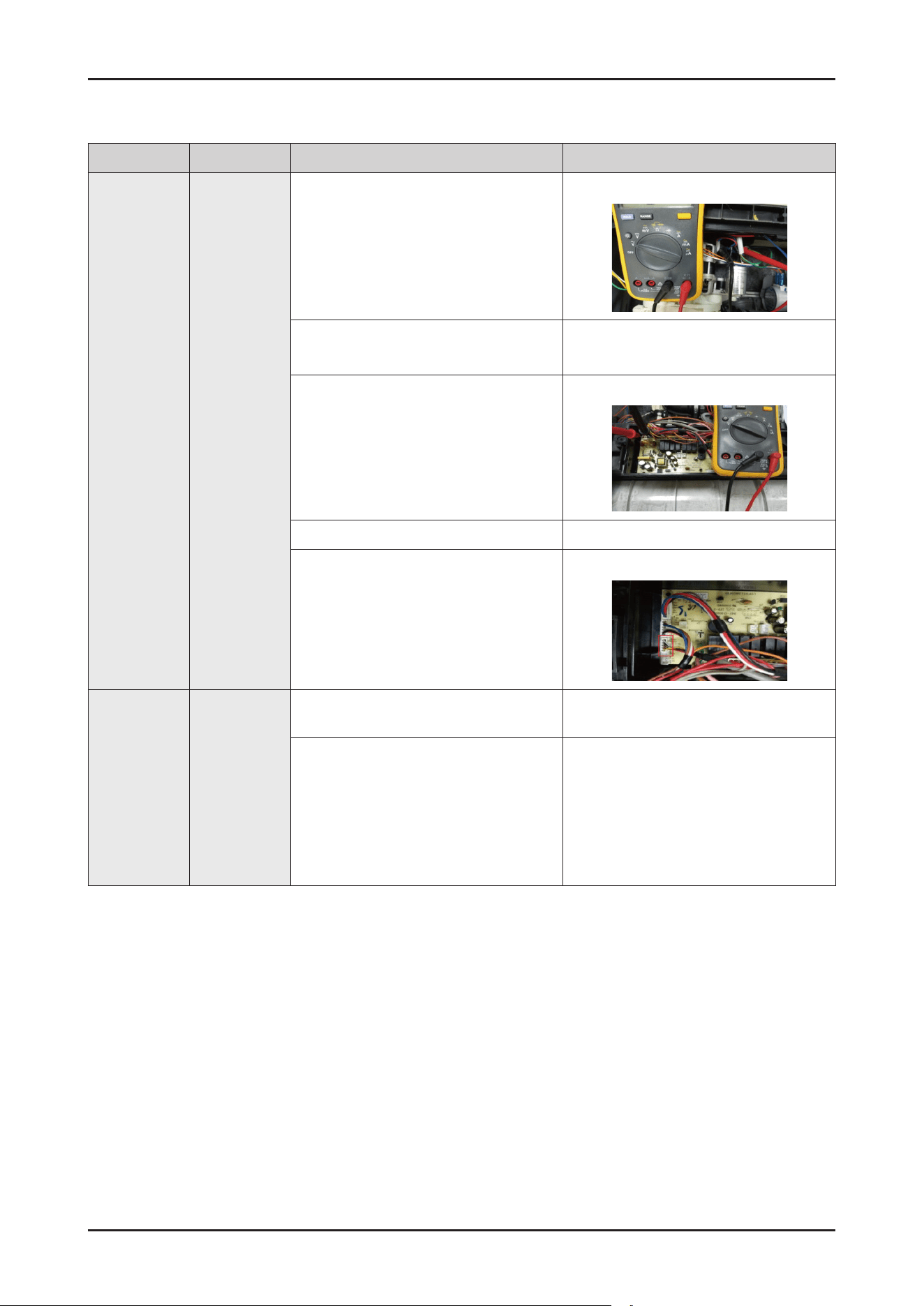
SAMSUNG PROPRIETARY. DO NOT COPY OR DISTRIBUTE WITHOUT PERMISSION
SAMSUNG PROPRIETARY. DO NOT COPY OR DISTRIBUTE WITHOUT PERMISSION
This Document can not be used without Samsung’s authorization.
Error type Error mode Checking method Corrective actions
No power None
1. Check the power cord connection is
Okay or not.
Reconnect the power cord.
2. Check the voltage of the power outlet.
- Normal : AC 220-240V
Connect to a proper power source.
3. Check the PBA connector. - Faulty : Replace the main wire harness.
4. Check the “Power button” - Faulty : Replace the sub PBA.
5. Check the sub wire harness connection
is Okay or not.
Reconnect the sub wire harness.
Dry is not
satised.
None
1. Check whether Rinse Rell LED light or
not.
If Rinse Rell LED light, rell rinse in
Dispenser.
2. Check the operation of the dispenser.
- If rinse aids are not dispensed,
a dry error may occur
- Because the dishes are heated and heat
dried during the last drying cycle, the
dried state of plastic dishes may not be
optimal
See “Detergent is not dispensed”.
Troubleshooting _ 115
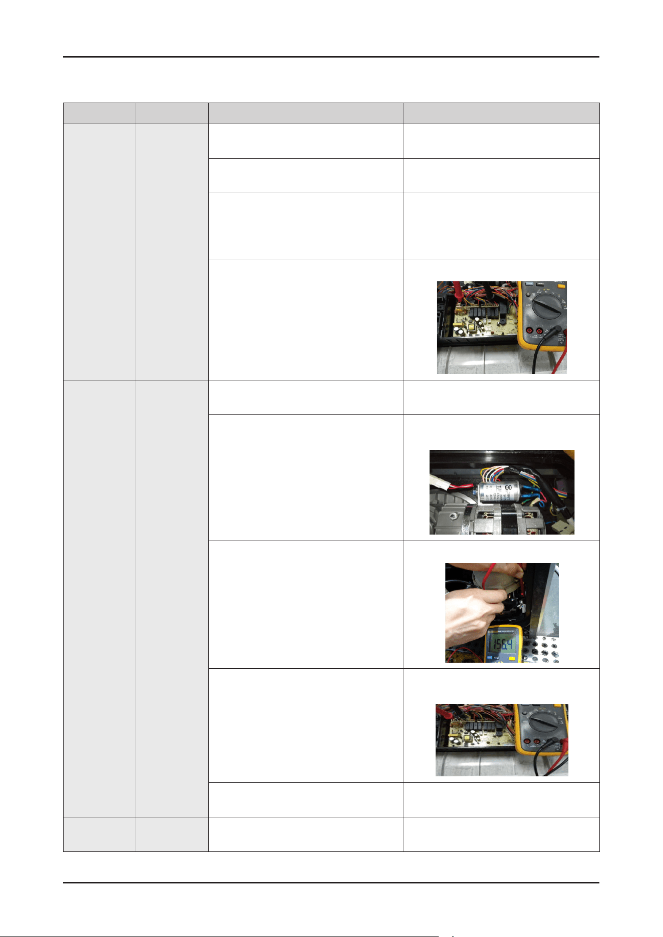
SAMSUNG PROPRIETARY. DO NOT COPY OR DISTRIBUTE WITHOUT PERMISSION
SAMSUNG PROPRIETARY. DO NOT COPY OR DISTRIBUTE WITHOUT PERMISSION
This Document can not be used without Samsung’s authorization.
Error type Error mode Checking method Corrective actions
Detergent is
not dispensed
None
1. Check whether detergent is inserted
into the dispenser
- Check whether there is detergent in the
Dispenser.
2. Check the connections for the Dispenser
connector.
- Reconnect the Dispenser connector.
3. Check the resistance of the Dispenser.
(Remove the connector before measure.)
- Normal Approx : 6.2Kohm
(BITRON dispenser : GRAY body)
- Faulty: Replace the Dispenser.
4. Check the operation of the Dispenser
Relay Check the operating of voltage
between the GREY wire of the CON3
connector and the BLUE wire of the
CON1 connector.
(while Dispenser is operating)
- Normal Approx:230V
- Faulty: Replace the Main PBA assy
The nozzle
does not inject
water
None
1. Check the connections for the circula-
tion Motor connector.
- Reconnect the Circulation Motor connector
2. Check the connections for the
Condenser connector of the Circulation
motor.
- Reconnect the start up condenser
connector of the Circulation Motor.
3. Check the resistance for the Circulation
Motor coil. (remove the connector before
measuring)
- Normal : Approx 157ohm for main coil
Approx 115hm for sub coil
- Faulty: Replace the Circulation Motor
4. Check the operation of the Circulation
Motor Relay :
Check the operating voltage between
the BLACK and YELLOW wire of the
CON2 connector and the BLUE wire of
the CON1 connectoron the MainPBA.
- Normal:230 V(while operating)
- Faulty: Replace the Main PBA assy.
- Normal: Replace the Circulation Motor.
5. Check whether there is foreign material
in the water passages.
Remove foreign material from the water
passages.
No washing None
1. Check whether the nozzle injects water
normally.
- See" The nozzle does not inject water".
116 _ Troubleshooting
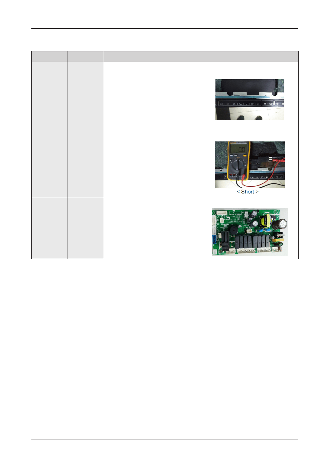
SAMSUNG PROPRIETARY. DO NOT COPY OR DISTRIBUTE WITHOUT PERMISSION
SAMSUNG PROPRIETARY. DO NOT COPY OR DISTRIBUTE WITHOUT PERMISSION
This Document can not be used without Samsung’s authorization.
Error type Error mode Checking method Corrective actions
The cycle does
not start
None
1. Check the connections for the Door
Sensing Switch.
- Reconnect the Door Sensing Switch
connector.
2. Check the operation of the Sensing
Switch. (Removing the connector before
measuring.):
- Normal: OPEN (when the door is open)
- Normal: SHORT(when the door is closed)
- Faulty: Replace the Door Sensing Switch.
- Normal: Replace the Main PBA assy.
Main PBA DC
voltage error
None
1. Check the DC voltage of the Main PBA
measure the voltage of E3.
- Normal: Approx 12V measure the
voltage of E7
- Normal: Approx 5V.
- Faulty: Replace the Main PBA assy.
Troubleshooting _ 117
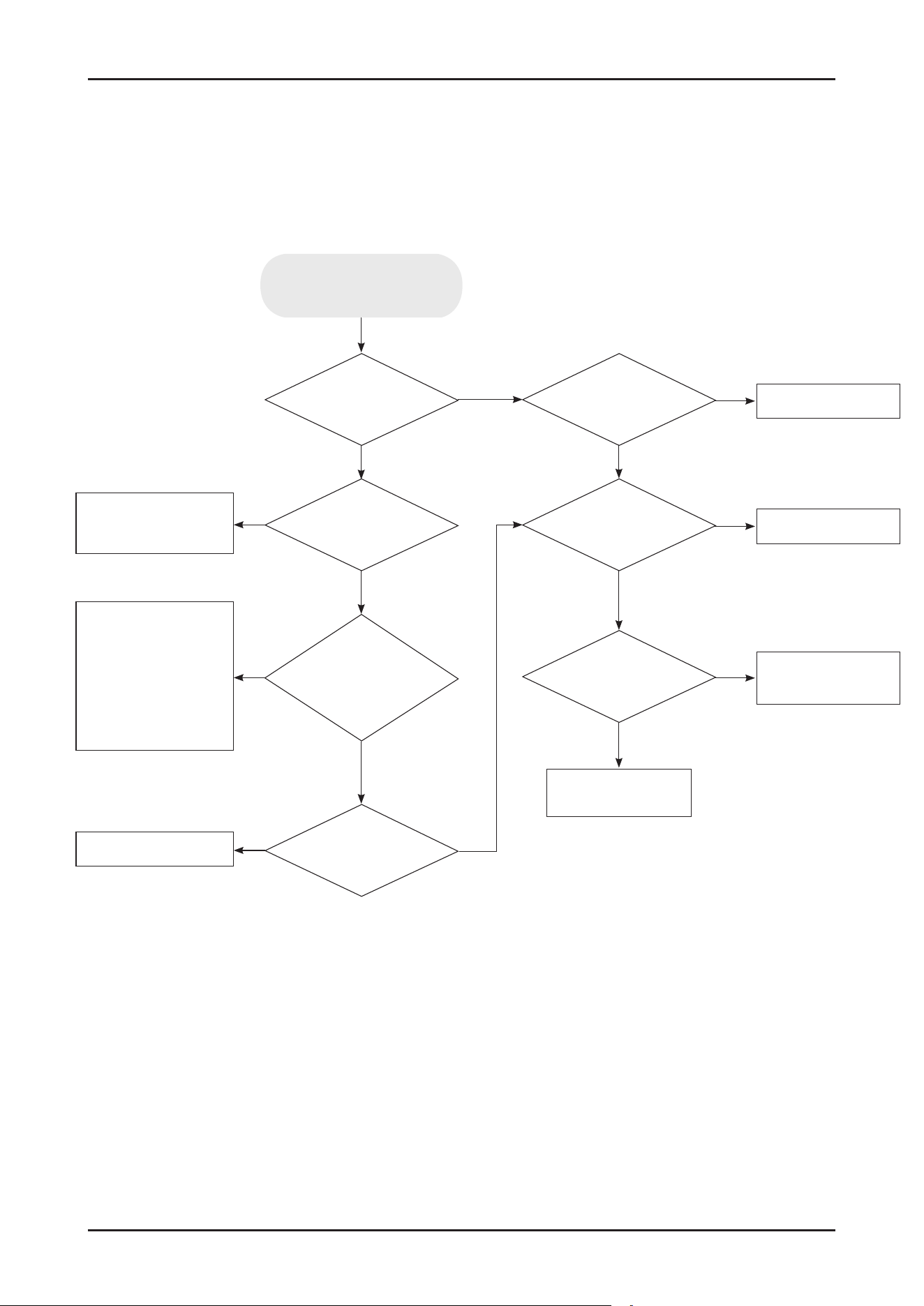
SAMSUNG PROPRIETARY. DO NOT COPY OR DISTRIBUTE WITHOUT PERMISSION
SAMSUNG PROPRIETARY. DO NOT COPY OR DISTRIBUTE WITHOUT PERMISSION
This Document can not be used without Samsung’s authorization.
4-5. Check Code Trouble Shooting
* Resolution of Information Codes
Water level is
enough in tub?
Drain pump
works
normally?
Flow-meter works
normally?
Pressure switch
works normally?
Reconnect water
faucet properly.
Replace aqua stop
or
Reconnect the
terminal properly
or
Remove foreign
substance in lter
Replace main PBA
Replace drain pump
Replace case brake
Replace pressure
switch
Check water duct
Water faucet
is Okay?
Aqua stop
is Okay? (Operating,
Filtering, terminal
connection)
Water
pressure is
OK?
No
No
No
No
No
No
Yes
Yes
Yes
No
Yes
Yes
Yes
Yes
4C occur
118 _ Troubleshooting
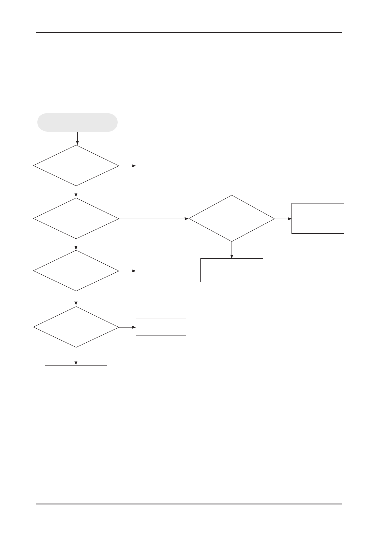
SAMSUNG PROPRIETARY. DO NOT COPY OR DISTRIBUTE WITHOUT PERMISSION
SAMSUNG PROPRIETARY. DO NOT COPY OR DISTRIBUTE WITHOUT PERMISSION
This Document can not be used without Samsung’s authorization.
Check Code Trouble Shooting
* Resolution of Information Codes
Heater works
normally?
Water level is
enough in tub?
Is the drain
hose installed under
minimum height?
(30 cm)
Pressure switch works
normally?
Filters are
clear without clogging by
food?
Replace heater
assembly
Check
the Water Valve and
Case Brake
Replace pressure
switch
Clean up the lters
Replace main PBA
Install the drain hose
again higher 30 cm
Yes
Yes
Yes
Yes
Yes
No
No No
No
No
HC occur
* See the ‘Connection of Drain hoses’ section on page 7.
Troubleshooting _ 119
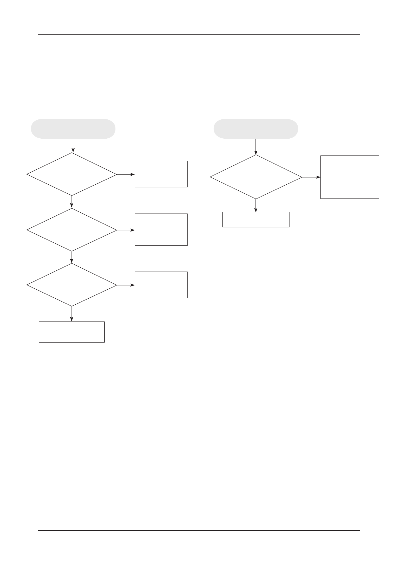
SAMSUNG PROPRIETARY. DO NOT COPY OR DISTRIBUTE WITHOUT PERMISSION
SAMSUNG PROPRIETARY. DO NOT COPY OR DISTRIBUTE WITHOUT PERMISSION
This Document can not be used without Samsung’s authorization.
Check Code Trouble Shooting
* Resolution of Information Codes
Is there any water
on Cover Base?
Is the terminal
of leakage sensor
disconnected?
Is there
any mechanical damage on
cover base?
Wipe water and dry
the cover base
Reconnect the
terminal of leakage
sensor
Replace cover
base assembly
Replace leakage
sensor
No
No
No
Yes
Yes
Yes
LC occur
Thermistor works
normally?
Replace thermistor
or
Check the Main Wire
harness
Replace main PBA
Yes
No
tC occur
120 _ Troubleshooting
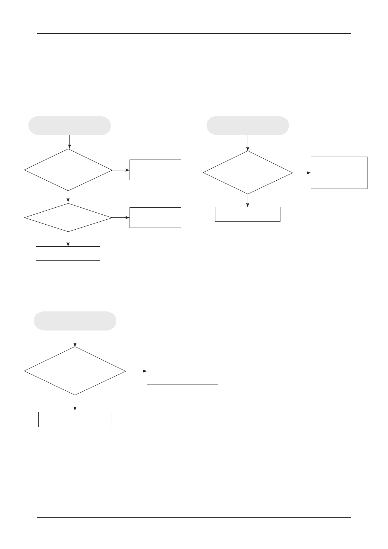
SAMSUNG PROPRIETARY. DO NOT COPY OR DISTRIBUTE WITHOUT PERMISSION
SAMSUNG PROPRIETARY. DO NOT COPY OR DISTRIBUTE WITHOUT PERMISSION
This Document can not be used without Samsung’s authorization.
Is the wire harness
(from Main PBA to touch PBA)
OK?
Replace the wire
harness
Replace the
display PBA
Replace main PBA
Is display PBA OK?
Yes
No
No
Yes
AC occur
Distribution
motor works normally (include
micro switch)?
Replace the
Distribution motor
assembly
Replace main PBA
Yes
No
PC occur
Is there any water or
foreign substance on the
touch key?
Replace the Display PBA
with Control Panel.
Clean up the touch key
Yes
No
bc2 occur
Check Code Trouble Shooting
* Resolution of Information Codes
Troubleshooting _ 121
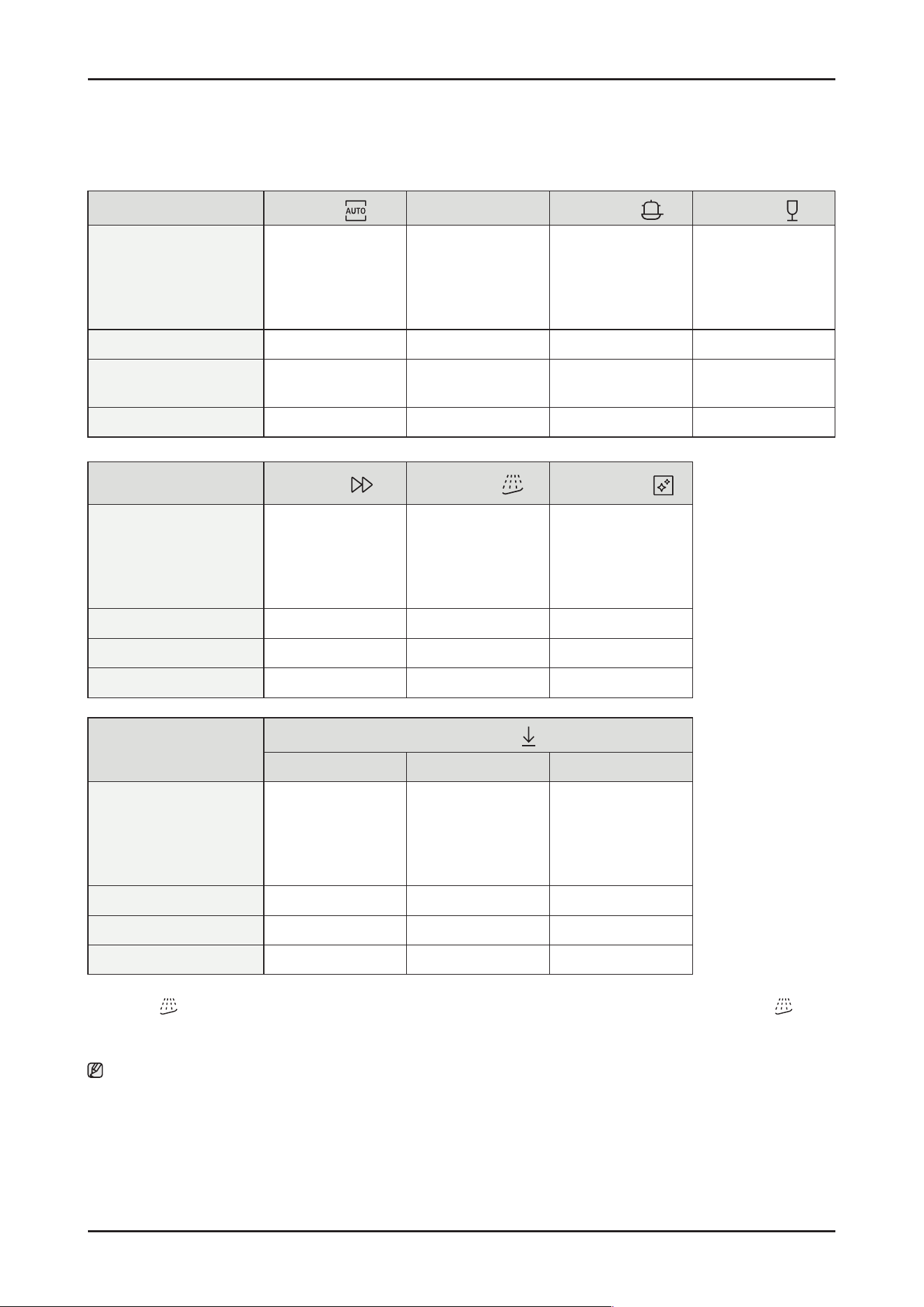
SAMSUNG PROPRIETARY. DO NOT COPY OR DISTRIBUTE WITHOUT PERMISSION
SAMSUNG PROPRIETARY. DO NOT COPY OR DISTRIBUTE WITHOUT PERMISSION
This Document can not be used without Samsung’s authorization.
4-6. Cycle chart
Cycle
AUTO
ECO
Intensive
Delicate
Cycle sequence
Pre wash (45 °C) >
Main wash (55-65 °C) >
Rinse >
Hot Rinse (50- 58 °C) >
Dry > End
Main wash (48 ° C) >
Rinse >
Hot Rinse (45 °C) >
Dry > End
Pre wash (50 °C) >
Main wash (65 °C) >
Rinse >
Hot Rinse (63 °C) >
Dry > End
Pre wash (40 °C) >
Main wash (50 °C) >
Rinse (50 °C) >
Hot Rinse (50 °C) >
Dry > End
Water consumption (L) 7.8-17. 3 10.5 17.3 13.9
Energy consumption (kWh) 0.650-1.500
0.746 (14 P/S)
0.735 (13 P/S)
1.535 0.950
Cycle time (min.) 129-150 220 205 120
Cycle
Express
Pre Wash *
Machine Care
Cycle sequence
Main wash (60 °C) >
Rinse (50 °C) >
Hot Rinse (63 °C) >
Dry > End
Pre wash > End Pre wash >
Main wash (70 °C) >
Rinse >
Hot Rinse (70 °C) >
Dry > End
Water consumption (L) 12.1 4.1 14.9
Energy consumption (kWh) 1.050 0.02 1.510
Cycle time (min.) 60 15 145
Cycle
Download cycle
Plastic Pots & Pans Baby Care
Cycle sequence
Pre wash >
Main wash (60 °C) >
Rinse >
Hot Rinse (60 °C) >
Dry > End
Pre wash (50 °C) >
Main wash (68 °C) >
Rinse >
Hot Rinse (70 °C) >
Dry > End
Pre wash >
Rinse >
Hot Rinse (70 °C) >
Dry > End
Water consumption (L) 14.1 21.5 10.6
Energy consumption (kWh) 1.080 1.610 0.755
Cycle time (min.) 129 172 79
* Pre Wash : This cycle does not activate the AutoRelease™ function nor the drying process. Continuous use of the Pre Wash cycle
for an extended time is not recommended. This may reduce the performance of the water softener.
Note
• The cycle time depends on the options you have added, and the pressure and temperature of the supplied water.
• The power consumption depends on the water temperature and/or load.
• Energy values for courses were calculated under standardized testing conditions.
122 _ Troubleshooting
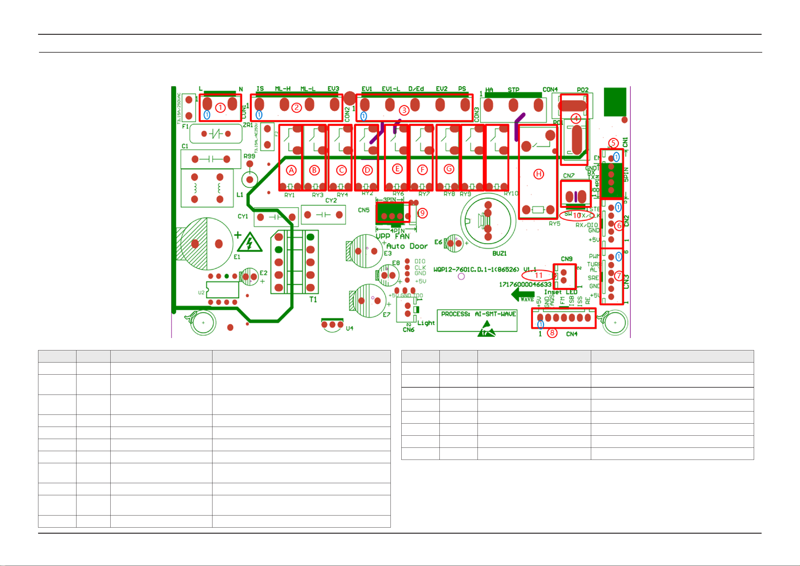
PCB Diagram _ 123
5. PCB DIAGRAM
5-1. FUNCTION OF CONNECTORS & RELAYS (MAIN PCB )
SAMSUNG PROPRIETARY. DO NOT COPY OR DISTRIBUTE WITHOUT PERMISSION
SAMSUNG PROPRIETARY. DO NOT COPY OR DISTRIBUTE WITHOUT PERMISSION
SAMSUNG PROPRIETARY. DO NOT COPY OR DISTRIBUTE WITHOUT PERMISSION
SAMSUNG PROPRIETARY. DO NOT COPY OR DISTRIBUTE WITHOUT PERMISSION
This Document can not be used without Samsung’s authorization.
Location Part No. Part name Function
1 CON1 Power supply Receive 230V AC to operate the PBA
2 CON2
Terminal for washing motor,
distributary valve, and Door lock
Connect with washing motor driving terminal, distributary valve
driving terminal, Door lock.
3 CON3 Terminal for each driving section
For water inlet valve , detergent dispenser, regeneration valve, drain
pump
4 P01, P02 Heater connection terminal Connect with heater
5 CN1 WIFI connection terminal Connect with wi module
6 CN2 Interface PBA connection terminal Connect with interface PCB
7 CN3 Turbidity sensor and ALT Turbidity sensing and ALT checking
8 CN4
Terminal for dishwasher operating
state-sensing
Overowing detect, salt empty and rinse add detect,
owmeter detect, water temperature sensing
9 CN5 Auto door connection terminal Connect with auto door
10 CN7
Waterless pressure micro switch
connection terminal
Connect with waterless pressure micro switch
11 CN9 Ground led connection terminal Connect with ground light (FBI model only)
Location Part No. Part name Function
A RY1 Washing motor relay For driving washing motor
B RY3 Washing motor low speed control relay For low speed washing
C RY4 Distributary valve relay For driving distributary valve
D RY2 Water inlet valve relay For driving water inlet valve
E RY6 Dispenser relay For driving dispenser
F RY7 Regeneration valve relay For driving regeneration valve
G RY8 Drain pump relay For driving drain pump
H RY5 Heater relay For driving heater power
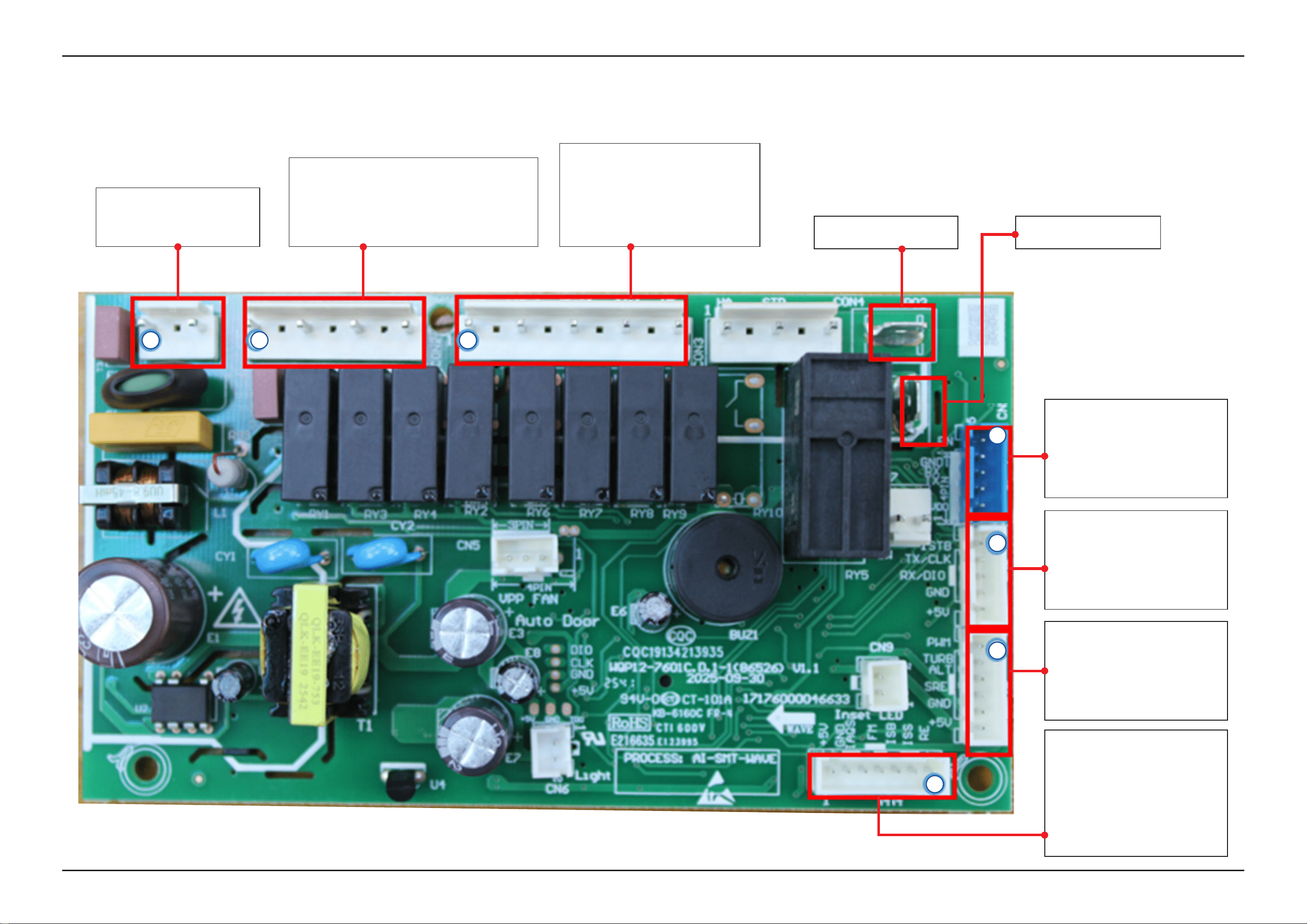
124 _ PCB Diagram
SAMSUNG PROPRIETARY. DO NOT COPY OR DISTRIBUTE WITHOUT PERMISSION
SAMSUNG PROPRIETARY. DO NOT COPY OR DISTRIBUTE WITHOUT PERMISSION
SAMSUNG PROPRIETARY. DO NOT COPY OR DISTRIBUTE WITHOUT PERMISSION
SAMSUNG PROPRIETARY. DO NOT COPY OR DISTRIBUTE WITHOUT PERMISSION
This Document can not be used without Samsung’s authorization.
5-2. DETAILED DESCRIPTION OF CONNECTORS & TERMINALS (MAIN PBA )
▶ P01: Heater connection ▶ P02: Heater connection
▶ CON1
1. L: terminal for 230vac power
3. N: terminal for 230vac power
▶ CON2
1. Door Switch
3. Connect with washing motor high speed terminal
5. Connect with washing motor low speed terminal
7. Connect with distributary valve
▶ CON3
1. EV1: connect with water inlet valve
3. EV1-L: terminal for 230vac power
5. D/Ed: connect with dispenser valve
7. EV2: connect with regeneration valve
9. PS: Connect with drain pump
▶ CN4
1. RE: Water temperature sensing
2. ISS: Salt empty detect
3. ISB: Rinse add detect
4. FM: Flow meter signal
5. IAQS: Overowing signal
6. GND
7. +5V
▶ CN3
1. PWM
2. TURB: TURBIDITY signal
3. ALT: Distributary valve signal
4. SRE (NOT)
5. +5V
▶ CN2
1. STB(NOT)
2. TX
3. RX
4. GND
5. +5V
▶ CN1
1. EN-WiFi
2. GND
3. RX
4. TX
5. VDD
1 1 1
1
1
1
1
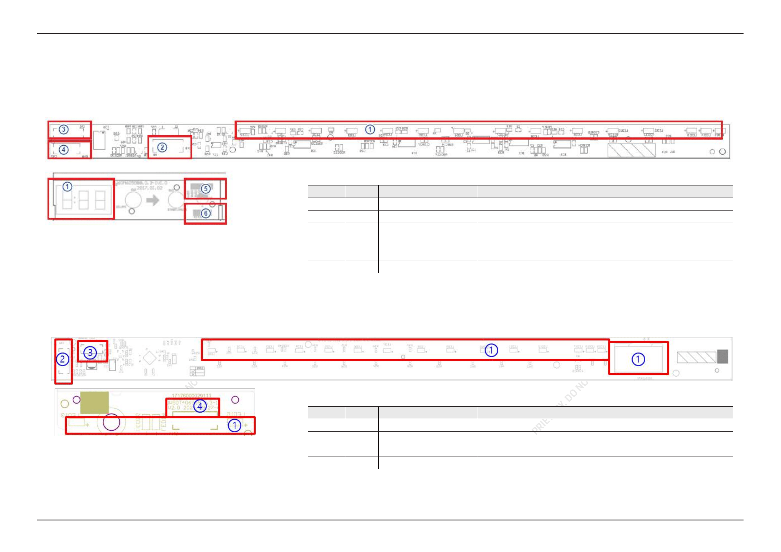
PCB Diagram _ 125
SAMSUNG PROPRIETARY. DO NOT COPY OR DISTRIBUTE WITHOUT PERMISSION
SAMSUNG PROPRIETARY. DO NOT COPY OR DISTRIBUTE WITHOUT PERMISSION
SAMSUNG PROPRIETARY. DO NOT COPY OR DISTRIBUTE WITHOUT PERMISSION
SAMSUNG PROPRIETARY. DO NOT COPY OR DISTRIBUTE WITHOUT PERMISSION
This Document can not be used without Samsung’s authorization.
5-3. FUNCTION OF CONNECTORS & TERMINALS (SUB PCB)
■ DW70H73WCB0U1
■ DW70H73YCFRU1
Location PART No. Function Description
1 LED Time Display Display state and washing program
2 CN3 UI PCBA CONNECTOR Connect with main PCBA (+5V, GND, RX, TX)
3 CN1 UI PCBA CONNECTOR Connect with the Digital PCBA (+5V, GND, COM7-COM4)
4 CN2 UI PCBA CONNECTOR Connect with Digital PCBA (K1-K4)
5 CN1 UI PCBA CONNECTOR Connect with LED PCBA (+5V, GND, COM7-COM4)
6 CN2 UI PCBA CONNECTOR Connect with LED PCBA (K1-K4)
Location PART No. Function Description
1 LED Time Display Display state and washing program
2 CN1 UI PCBA CONNECTOR Connect with main PCBA (+5V, GND, RX, TX)
3 CN2 UI PCBA CONNECTOR Connect with the LED PCBA (GND, B/STB, C/CLK, D/DIO, COM2D/5V)
4 CN4 UI PCBA CONNECTOR Connect with display PCBA (GND, B/STB, C/CLK, D/DIO, COM2D/5V)
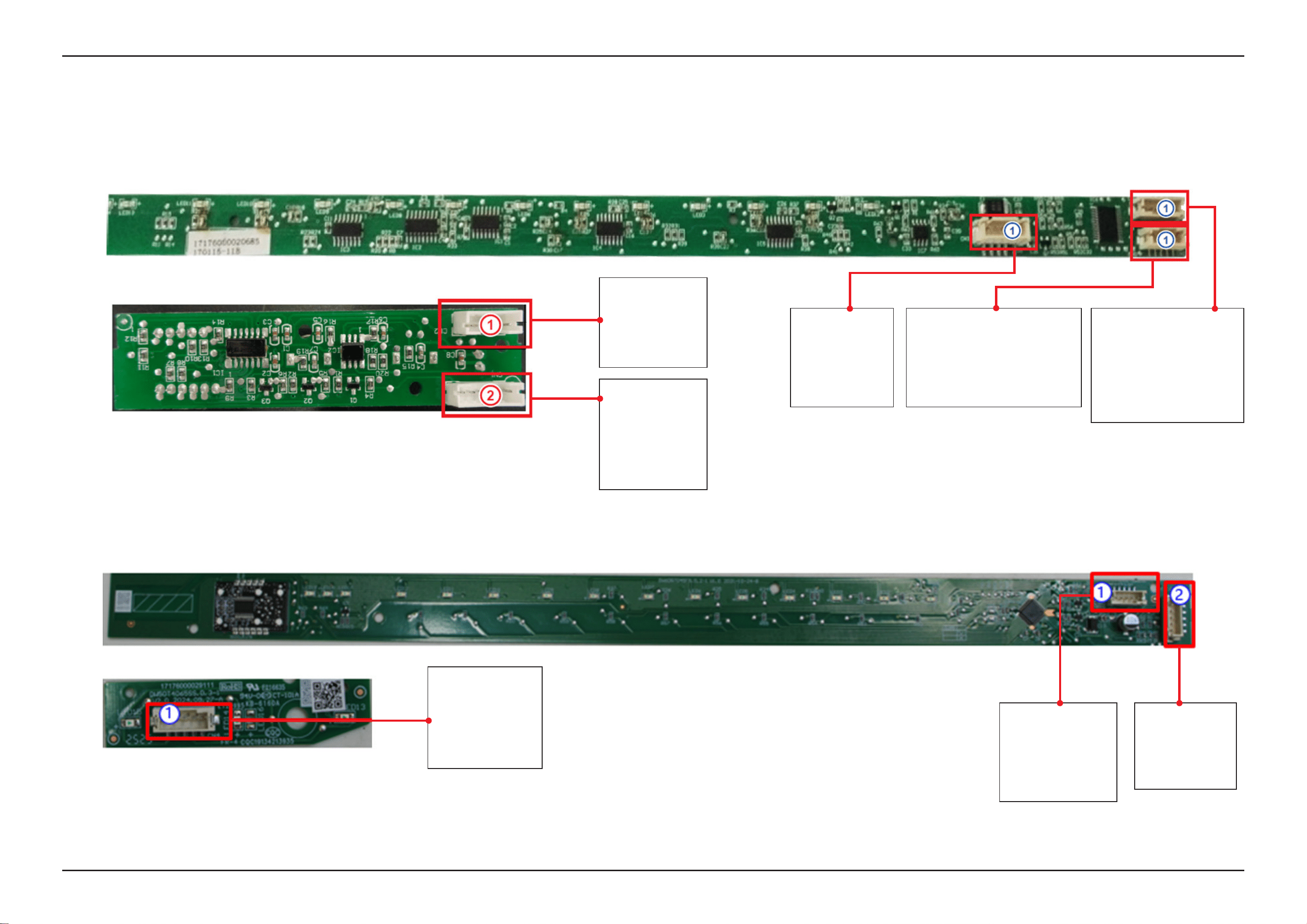
126 _ PCB Diagram
SAMSUNG PROPRIETARY. DO NOT COPY OR DISTRIBUTE WITHOUT PERMISSION
SAMSUNG PROPRIETARY. DO NOT COPY OR DISTRIBUTE WITHOUT PERMISSION
SAMSUNG PROPRIETARY. DO NOT COPY OR DISTRIBUTE WITHOUT PERMISSION
SAMSUNG PROPRIETARY. DO NOT COPY OR DISTRIBUTE WITHOUT PERMISSION
This Document can not be used without Samsung’s authorization.
5-4. DETAILED DESCRIPTION OF CONNECTORS & TERMINALS (SUB PBA)
■ DW70H73WCB0U1
■ DW70H73YCFRU1
▶ CN2
1. K1
2. K2
3. K3
4. K4
▶ CN3
1: +5V
2: GND
3: RX
4: TX
5: Not use
▶ CN2
1. not use
2. K4 Digital clock output
3. K3 Digital data output
4. K2 Delay key Sensor
5. K1 START/PAUSE key Sensor
▶ CN1
1. +5V
2. GND
3. COM7 not use
4. COM6 display common
5. COM5 display common
6. COM4 display common
▶ CN1
1. 5V
2. GND
3. COM7
4. COM6
5. COM5
6. COM4
▶ CN1
1. GND
2. B/STB
3. C/CLK
4. D/DIO
5. COM2D/5V
▶ CN2
1. GND
2. B/STB
3. C/CLK
4. D/DIO
5. COM2D/5V
▶ CN1
1. +5V
2. GND
3. RX
4. TX
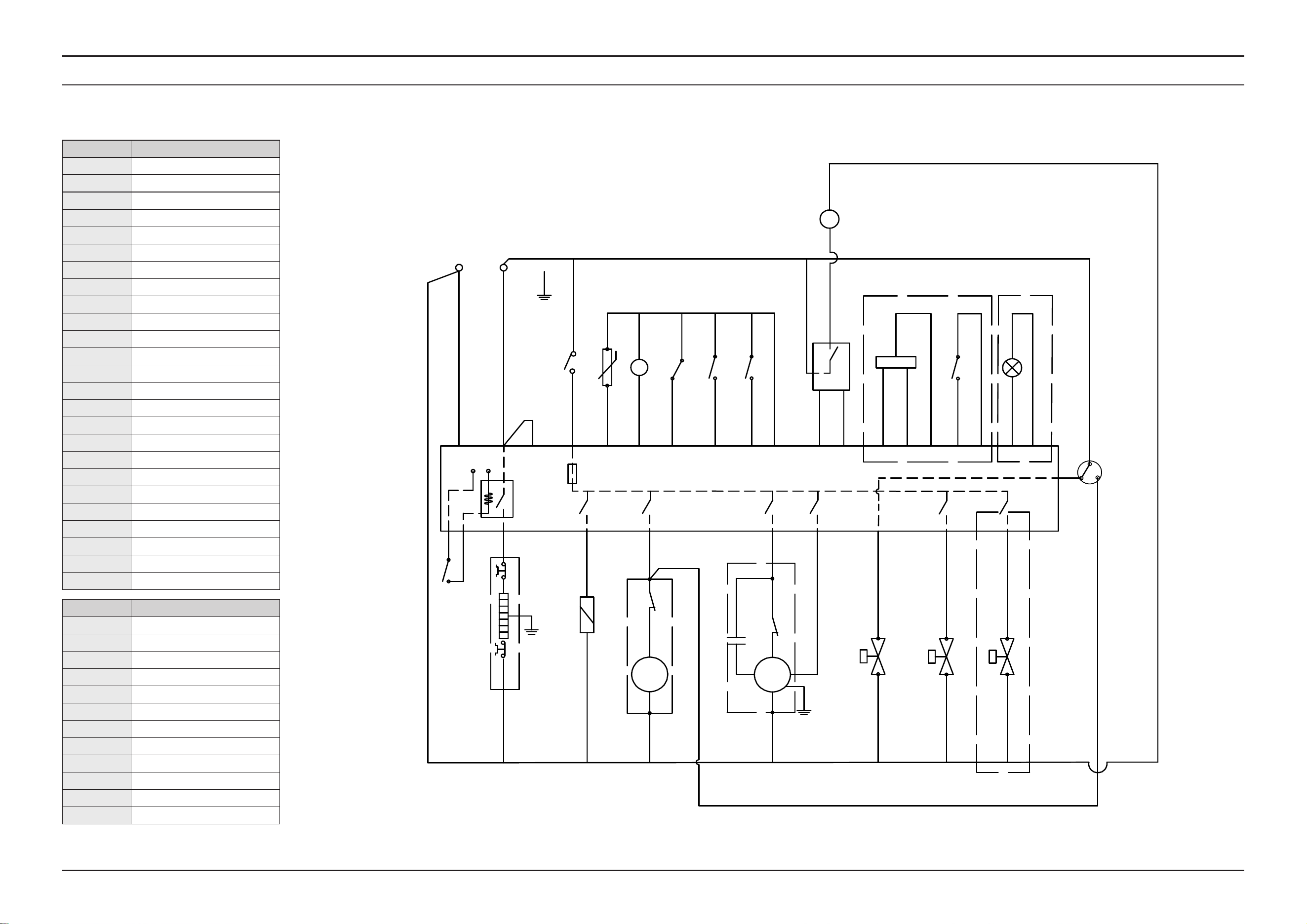
SAMSUNG PROPRIETARY. DO NOT COPY OR DISTRIBUTE WITHOUT PERMISSION
SAMSUNG PROPRIETARY. DO NOT COPY OR DISTRIBUTE WITHOUT PERMISSION
SAMSUNG PROPRIETARY. DO NOT COPY OR DISTRIBUTE WITHOUT PERMISSION
SAMSUNG PROPRIETARY. DO NOT COPY OR DISTRIBUTE WITHOUT PERMISSION
This Document can not be used without Samsung’s authorization.
Wiring Diagram _ 127
6. WIRING DIAGRAM
6-1. WIRING DIAGRAM
CODE Designation
ACL Live (Alternating Current)
ACN Neutra (Alternating Current)
E Earth
EV1 Inlet Valve
EV2 Softener Valve
EV3 Water Distribution Valve
IAQS Overow Switch
FM Flow Meter
ISB Rinse Aid Detector
ISS Salt Detector
DIV Water Distribution Valve Switch
RE Temperature sensor (NTC)
CODE Designation
P1 Water Level Switch (135/115)
P2 Dry Heating Protect Switch
ML Wash Pump
PS Drain Pump
FUSE Fuse (3.15A)
R Heater
DOOR Door Switch
IS Door Switch
NS Nephelometer
LED Indicator light
VM Auto open door
D/Ed Dispenser
Abbreviation Meaning
BU Blue
YE Yellow
GN Green
WH White
RD Red
BK Black
PK Pink
GY Gray
OR Orange
BR Brown
PU Purple
YE+GN Yellow/Green bicolor
BK
BU
RD
BU
BU
BR
N
L
P01
PS
ML
PS
D/Ed
D/Ed
ML-H
P02
EV1-L
C
R
BK
GY
RD
ACN
220V 50HZ
YE+GN
EV1
EV1
BU
BU
GY RD
WH
BU
PK
ACL
ML-L
TURB
+5V
Turbidty
PWM
RD
BK
VPP
BR BK
P1
IS
FUSE
DOOR
YE
RD
YE
BR
BR
BR
BR
RD
EV2
EV2
PU
PU
EV3
EV3
OR
OR
P2
+12V
GND
BR
VM
BU
BU
BK
WH
GND
FM
ISBIAQS
ISS
FM
WH
BK
ISB
RE
GY
BU
GY
RD
RE
2
1
IAQS
RD
ISS
ALT
YE
+12V
DIV
GND
PU
YE
RD
BK
LED+12V
Optional
BK
Optional
Optional
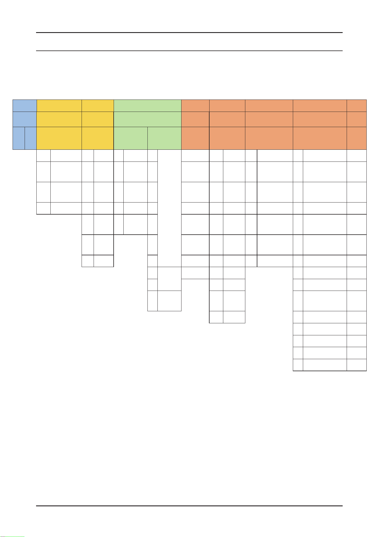
128 _ Reference
SAMSUNG PROPRIETARY. DO NOT COPY OR DISTRIBUTE WITHOUT PERMISSION
SAMSUNG PROPRIETARY. DO NOT COPY OR DISTRIBUTE WITHOUT PERMISSION
This Document can not be used without Samsung’s authorization.
7. REFERENCE
7-1. MODEL NUMBER NAMING RULES
► This Document can not be used without Samsung’s authorization.
① ② ③ ④ ⑤ ⑥ ⑦
⑧ ⑨
⑩ ⑪ ⑫ ⑬
PRODUCT SERIES YEAR CAPACITY (TYPE) DERIVATION ENERGY INSTALLATION TYPE CMF
BUYER
CODE
D W 90 F 8 0 A 0 U S
99 Innite D 2024 9 24"C/D T 9
3 Racks
A A A U Built Under W CLEAN WHITE
90
3rd Washing
System
F 2025 8 24"T 8 B B B T
Built Under
(Bar Type)
X SATIN WHITE
80 - H 2026 7 24 7 C C C I
Fully Built-In
(Sliding door)
Y COTTA PCM WHITE
70 - J 2027 5 18" 6 D D D B Fully Built-In Z ESSENTIAL WHITE
K 2028 3 C/T 5 E E E S Semi Built-In V
SNOW WHITE
(DA White)
M 2029 4 F M F Free Standing D
ESSENTIAL DARK
METAL
N 2030 3 … 1 A-10% C Counter-top E MATT BLACK
2
2 Racks
Z 2 A-15% F BLACK DOI
1 3
A-20% G ESSENTIAL BEIGE
0
1 Rack
(C/T)
4 A-25% R REAL STAINLESS
5 A-30% T MATT DOI METAL
J SATIN BEIGE
L Timeless Greige
M Timeless Charcoal
0 Custom Panel
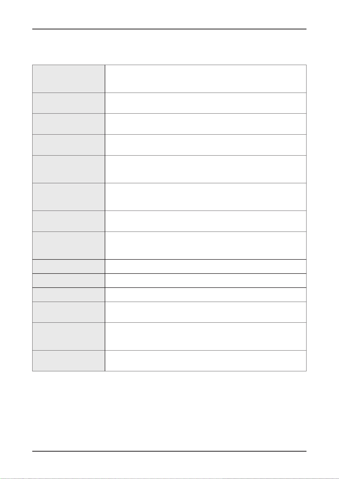
Reference _ 129
SAMSUNG PROPRIETARY. DO NOT COPY OR DISTRIBUTE WITHOUT PERMISSION
SAMSUNG PROPRIETARY. DO NOT COPY OR DISTRIBUTE WITHOUT PERMISSION
This Document can not be used without Samsung’s authorization.
Circulation motor
A motor that sucks the water remaining on the oor of the dishwater and injects
water using high pressure through the internal water passages to the top.
Middle and lower nozzles.
Drain pump
The pump that drains the polluted water from the dishwater generated while the
dishwater is running.
Heater
The heater is located on the water passages inside the dishwasher.
It heats the owing water to increase wash efciency.
Flow meter
Measure the amount of supplied water by counting the pulses of the hall IC located
at the next of the inlet valve.
Distributor
Located at the output end of the sump inside the dishwasher. It turns the ow of the
water that goes to the bottom part of the dishwasher on or off.
(THIS MODEL DOES NOT HAVE THIS PART)
Dispenser
The location where the detergent and rinse aids are stored so they can be used by
the dishwasher. The dispenser automatically supplies detergent and rinse aids to the
inside of the dishwasher when they are needed.
Tub Assy
An internal case mode of stainless steel that makes up the basic framework of the
dishwasher.
Sump Assy
The place inside the dishwasher where water is collected. The injected water gathers
here after circulation. The sump Ass’y is connected to the circulation motor and drain
pump.
Door Assy An internal case made of stainless steel that makes up internal part of the front door.
Base Assy A plastic part that makes up the basic bottom framework.
Basket Assy The upper and lower racks where dishes can be loaded.
Top/Middle/Lower nozzles
Washes dishes by rotating and injecting the supplied water through the water
passage at high pressure.
Case brake
A passage that adjusts the air pressure by connecting the pressure of the inside air
which is expanded at high temperature during wash and rinse cycles and the outside
air pressure.
Door lock switch
Detects whether the door of the dishwasher is open or closed if the door is open while
the dishwasher is running the cycle is temporary stopped.
7-2. TERMINOLOGY

130 _ Reference
SAMSUNG PROPRIETARY. DO NOT COPY OR DISTRIBUTE WITHOUT PERMISSION
SAMSUNG PROPRIETARY. DO NOT COPY OR DISTRIBUTE WITHOUT PERMISSION
This Document can not be used without Samsung’s authorization.
7-3-1. SmartThings (Applicable models only)
■ Wiconnection
On your smartphone, go to Settings and connect to your home Wi-Fi network.
■ Download
On an app market (Google Play Store, Apple App Store, Samsung Galaxy Apps), nd the SmartThings app with a search
term of “SmartThings”. Download and install the app on your device.
■ Login
You must rst log into SmartThings with your Samsung account. To create a new Samsung account, follow the
instructions on the app. You don’t need a separate app to create your account.
Note
If you have a Samsung account, use the account to log in. A registered Samsung smartphone user automatically logs in.
■ Wi-FiOff
To manually turn the Wi off, press and hold ‘Speed boosting button’ and ‘Smart control button’ for 3 seconds at same
time.
■ ToregisteryourdevicetoSmartThings
1. Make sure your smartphone is connected to a wireless network.
2. Select to run SmartThings on your smartphone.
3. When a message of “A new device is found.”, select Add.
4. If no message appears, select + and select your dishwasher in a list of devices available.
If your dishwasher is not listed, select Device Type > Specic Device Model, and then add your dishwasher manually.
5. Follow the onscreen instructions to complete the connection process for your dishwasher.
6. When the process is complete, your dishwasher will appear in the list of devices on your SmartThings App.
7. iPhone user have to scan QR code or enter Serial Number(Code below the QR code) for using SmartThings app.
NOTE
Dishwasherapp
Integrated control:
You can monitor and control your dishwasher both at home and on the go.
Select the dishwasher icon on SmartThings . The dishwasher page appears.
Check the operation status or notications related to your dishwasher, and change options or settings if necessary.
NOTE
• This device is designed for household use only (Class B), and can be used in all residential areas.
• This device may cause wireless interference, and neither the manufacturer nor the installer of this device can provide
a safety measure of any kind. Recommended encryption methods are WPA/TKIP and WPA2/AES .
Newly developed Wi-Fi protocols or unapproved Wi-Fi protocols are not supported.
• The reception sensitivity of a wireless network may be affected by surrounding wireless environments.
• If your Internet provider has registered the MAC address of your PC or the modem module for permanent use, your Samsung
dishwasher fails to connect to the Internet. If this happens, contact your Internet provider.
7-3. SMARTTHINGS (APPLICABLE MODELS ONLY)
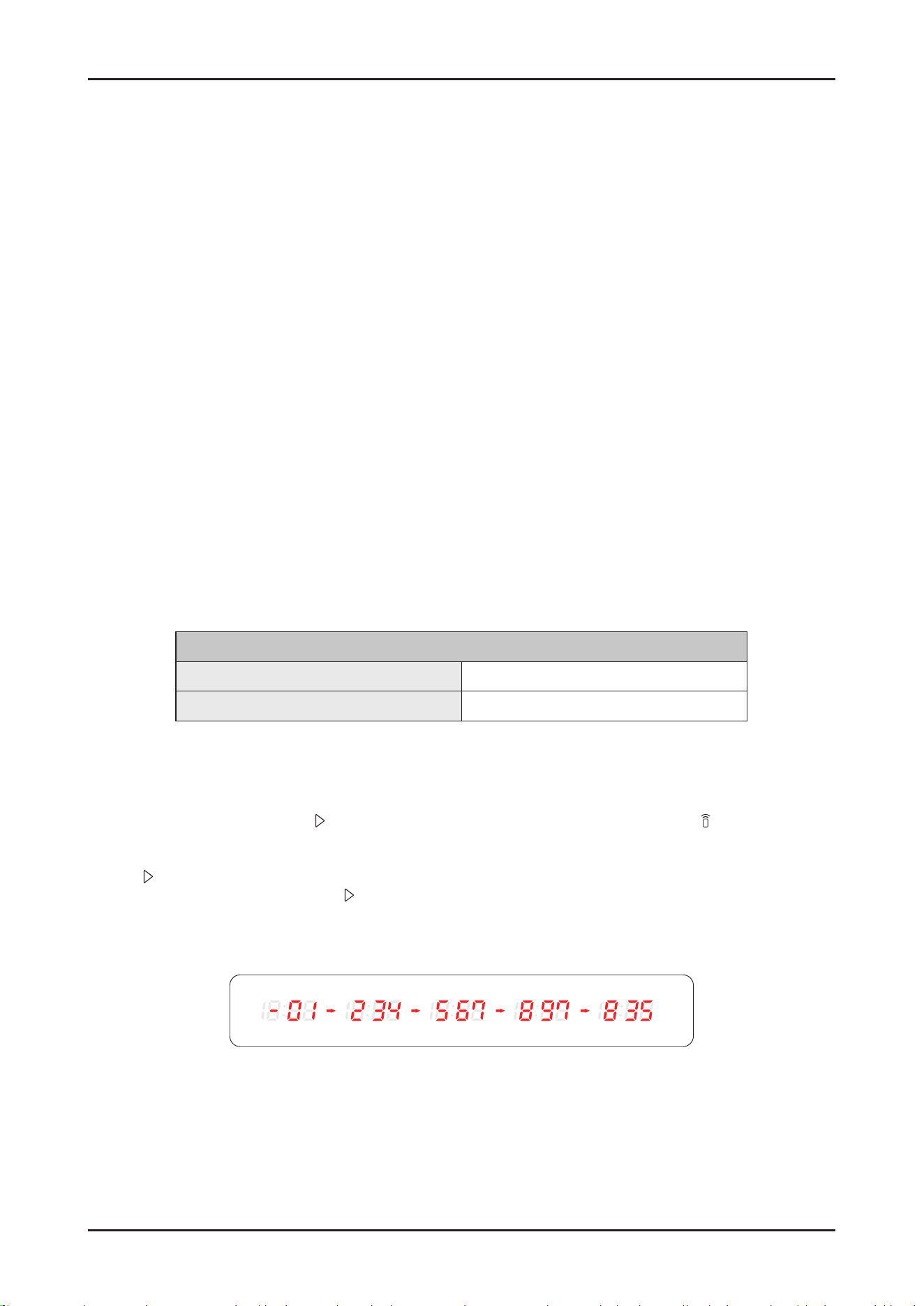
Reference _ 131
SAMSUNG PROPRIETARY. DO NOT COPY OR DISTRIBUTE WITHOUT PERMISSION
SAMSUNG PROPRIETARY. DO NOT COPY OR DISTRIBUTE WITHOUT PERMISSION
This Document can not be used without Samsung’s authorization.
• The Internet rewall may interrupt your Internet connection. If this happens, contact your Internet provider.
• If Internet failure continues after following the measurement of your Internet provider, contact a local Samsung retailer or
service centre.
• For installing wired and wireless routers, refer to the user manual of the router you use.
• Samsung dishwasher supports the Wi-Fi 2.4 GHz protocols.
• Samsung dishwasher supports the IEEE802.11 b/g/n (2.4 GHz), Soft-AP protocols. ( IEEE802.11n is recommended)
• An unapproved wired/wireless router may fail to connect to Samsung dishwasher.
• The SmartThings app is available on Android and iOS devices. The app is optimised for Samsung phones.
• Some functions of the app may operate differently on third-party devices.
• The app is subject to change without notice for improved performance.
• In addition, further updates on the app or the function in the app may stop caused by usability and security reasons, even if
updates are currently supported on your OS.
• Your device uses non-harmonised frequency and is intended for use in all European countries.
The WLAN can be operated in the EU without restriction indoors, but cannot be operated outdoors in France.
• You can easily install the SmartThings app or use the product with your phone by scanning the QR code on the attached label.
• Hereby, Samsung Electronics, declares that the radio equipment type appliance is in compliance with Directive 2014/53/
EU . The full text of the EU declaration of conformity is available at the following internet address: The ofcial Declaration of
conformity may be found at http://www.samsung.com , go to Support>SearchProductSupportand enter the model name.
• The overall standby power consumption is 2.0 W in which all network ports stay in “on” condition.
- Data determined according to standard E N 50564 and Regulation (EC) N o 1275/2008
Wi-Fi
Frequencyrange Transmitterpower(Max)
2412 MHz - 2472 MHz 20 dBm
■ WSN
1. How to access: tap and hold Start in AP mode. (To enter the AP mode, tap and hold Smart Control for 3 seconds.)
2. Display format
- After receiving WSN data from WiFi module, “-” + rst 2 digits are diplayed and next 3 digits are diplayed by every Start
button tapping.
- Beep is generated when the Start button is tapped for displaying digits.
- Display example : “-” for the starting display
ex) WSN : “ 01234567897835”
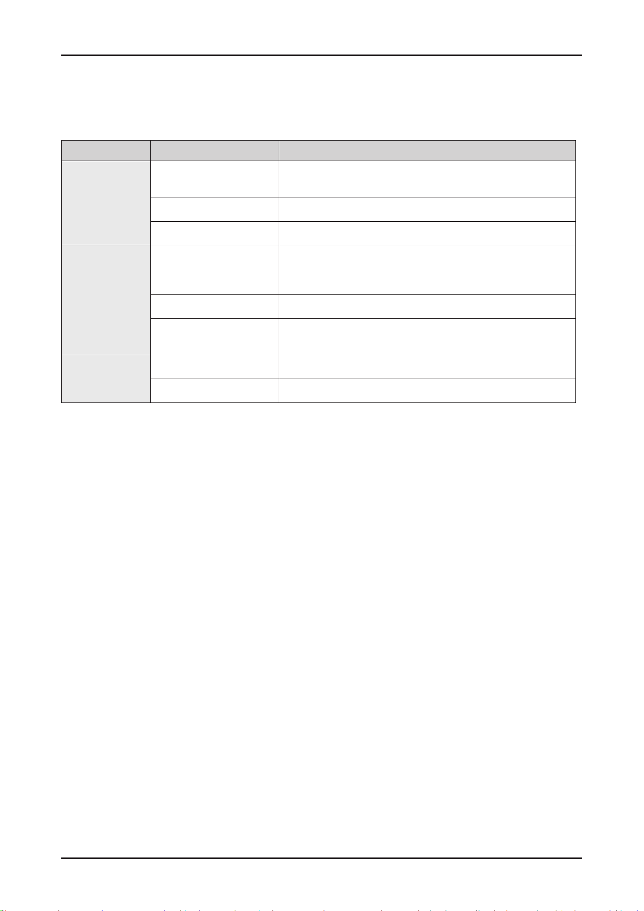
132 _ Reference
SAMSUNG PROPRIETARY. DO NOT COPY OR DISTRIBUTE WITHOUT PERMISSION
SAMSUNG PROPRIETARY. DO NOT COPY OR DISTRIBUTE WITHOUT PERMISSION
This Document can not be used without Samsung’s authorization.
7-3-2.SmartThingsfunctions
Category Function Description
Monitoring
Washing status
You can check the current cycle and its options, and the remaining
cycle time.
Smart Control The Smart Control status is shown for the dishwasher.
Energy monitoring Use this to monitor the energy consumption status.
Control
Start/ Pause/ Cancel
Select a cycle and necessary options, and then select Start/ Pause/
Cancel to start an operation, to stop temporarily, or to cancel the
current operation.
My Favorite Add frequently used cycles and options to My Favorite for later use.
Delay Start
Set Delay Start to start the cycle at a scheduled time
(up to 24 hours).
Notication
Cycle completed Noties you when the current cycle is complete.
Detergent Noties you if the dishwasher is out of rinse aid.
SAMSUNG PROPRIETARY. DO NOT COPY OR DISTRIBUTE WITHOUT PERMISSION
SAMSUNG PROPRIETARY. DO NOT COPY OR DISTRIBUTE WITHOUT PERMISSION
© 2026.02 Samsung Electronics Co.,Ltd.
All rights reserved.
Printed in Korea
GSPN (GLOBAL SERVICE PARTNER NETWORK)
Area Web Site
Eurpoe, CIS, Mideast & africa gspn1.samsungcsportal.com
Asia gspn2.samsungcsportal.com
North & Latin America gspn3.samsungcsportal.com
China china.samsungportal.com
This Service Manual is a property of Samsung Electronics Co.,Ltd.
Any unauthorized use of Manual can be punished under applicable International
and/or domestic law.