
6th Generation User Manual
All Component Types
LABBB6UM - Rev. 8
July 2026
All Together Better

Table of Contents
Precautions & Warnings ................................................................................................................................ 4
Support & Contact Information ...................................................................................................................... 5
CLEAN Support ..................................................................................................................................... 5
Bigbelly Support .................................................................................................................................... 5
Ordering Parts ...................................................................................................................................... 5
Commonly Used Tools & Materials ................................................................................................................. 6
Introduction .................................................................................................................................................. 7
The Bigbelly 6th Generation Product Lineup ............................................................................................ 8
Serial Number Ranges ................................................................................................................... 9
Main Board Maps ................................................................................................................................ 10
BB6 Product Specications ................................................................................................................. 12
Liner Bags for your 6th Generation Stations .................................................................................. 14
Safety Mechanisms ............................................................................................................................ 15
Bigbelly ACS (Access Control System) ................................................................................................. 15
Site Selection .............................................................................................................................................. 16
Station Protection & Side-Walk Considerations ...................................................................................... 16
Installation ................................................................................................................................................. 18
Receiving the Component .................................................................................................................... 18
Component Keys ........................................................................................................................ 19
Transporting the Component ............................................................................................................... 19
Removing the Component from the Pallet ............................................................................................. 19
Transporting the Component Without a Pallet ....................................................................................... 20
Installing and Securing the Component ................................................................................................ 21
Install and Secure a Single Component ......................................................................................... 21
Install and Secure a Multi-Bin Kiosk .............................................................................................. 22
Conguring Your Compactor for Indoor Use .................................................................................. 29
Activation: Turning on your Components .............................................................................................. 32
Testing Your Component ..................................................................................................................... 33
Removing the Front Door Release Cable Tie .......................................................................................... 33
CLEAN Mobile Install Procedure ................................................................................................................... 34
Operations .................................................................................................................................................. 38
LED Indicators .................................................................................................................................... 38
Compacting Stations (Sense Max and Smart Max) ................................................................................ 38
Manual Compaction Cycle (Smart Max and Sense Max Only) ......................................................... 38
Non-Compacting Stations (Sense and Sense Max Only) ......................................................................... 40
Compost Stations ............................................................................................................................... 40
Element Stations ................................................................................................................................. 40
Initiating a Service Visit (Compacting Components Only) ....................................................................... 41
Collections and Fullness ...................................................................................................................... 42
Fullness Threshold & Age Threshold ............................................................................................ 42
Liner Bags .................................................................................................................................. 42
Waste Removal & Routine Visual Inspection ................................................................................. 44
Battery Overview ................................................................................................................................. 45
Rechargeable Battery Overview .................................................................................................... 45
Non-Rechargeable Battery Overview ............................................................................................. 45
Replacing a Battery ..................................................................................................................... 45
Preparing a Component for Storage ..................................................................................................... 45
Routine Maintenance & Cleaning .................................................................................................................. 50
2
LABBB6UM - Rev. 8
July 2026

Scheduled Maintenance ...................................................................................................................... 50
Third & Sixth Month Maintenance ................................................................................................ 50
Ongoing Quarterly Maintenance ................................................................................................... 50
Power Maintenance - As Needed .................................................................................................. 50
Cleaning ............................................................................................................................................. 51
Routine Cleaning Maintenance ..................................................................................................... 51
Approved Cleaning Products ........................................................................................................ 52
Cleaning the Height Sensors ........................................................................................................ 53
Grafti Removal & Cover-Up ................................................................................................................. 54
Tools & Materials ........................................................................................................................ 54
Grafti & Sticker Removal ............................................................................................................ 55
Side Skin Grafti Cover-Up ........................................................................................................... 55
Troubleshooting .......................................................................................................................................... 57
Common Troubleshooting: Compacting Components ............................................................................ 57
Continuous Compaction Cycles or False Fullness .......................................................................... 57
Compaction Error: Solid Red LED (SR) .......................................................................................... 57
Common Troubleshooting: Components without Compactors ............................................................... 61
False Fullness ............................................................................................................................. 61
Solid Red While Front Door is Open .............................................................................................. 61
Common Troubleshooting: All Components .......................................................................................... 62
Front Door Does Not Stay Closed or Latched ................................................................................ 62
No LEDs Lit ................................................................................................................................ 62
Solid Yellow LED While Front Door is Open .................................................................................... 63
What to do if Problems Persist ............................................................................................................. 64
Compliance and Cer tications ..................................................................................................................... 65
Federal Communication Commission Class A ....................................................................................... 65
Waste Electrical and Electronic Equipment (WEEE) 2012/19/EU ............................................................. 65
EU Declaration of Conformity ............................................................................................................... 65
Revision Block ............................................................................................................................................ 66
3
LABBB6UM - Rev. 8
July 2026
Precautions & Warnings
NOTICE
Before attempting to service or maintain a BB6 Smart/Smart Max, Sense/Sense Max, Element, or
Compostthe contents of this manual must be read and understood. Failure to follow instructions in
this manual could void the warranty on theComponent.
OnlyBigbellycertied personnel should perform any service or repairs that go beyond the scope of
this manual.
The personnel involved in the installation, operation, or maintenance of theBigbelly system must read and understand
all warning labels in addition to the current version of the following applicable standards:
•
ANSI Standard No. Z245.2, "Stationary Compactors Safety Requirements." A copy of this standard may be obtained
from:
National Waste & Recycling Association
1550 Crystal Drive, Suite 804
Arlington, VA 22202
•
OSHA 29 CFR, Part 1910.147, "The control of hazardous energy (lockout/tagout)"
•
Products contain the following transmitter modules: FCC ID 2AC7Z-ESP32WROOM32E and FCC ID
RI7ME910G1WW.
If further assistance or training is needed, please contact your distributor orBig Belly Solar LLC. You will be asked to
provide theComponent serial number, location, and installation date.
CAUTION
Do not attempt to run theSmart Max / Sense MaxRam with theFront Door open. This could result in
harm to theComponent and possible harm to users.
TheBigbelly system is designed with user safety as a top priority. Labels inside theComponents indicate potentially
dangerous areas and safety hazards. Allpersonnel must familiarize themselves with these labels and locations.
CRUSH HAZARD
A warning label with this icon appears on the interior of theSmart Max and Sense Maxto warn of
theRam.
4
LABBB6UM - Rev. 8
July 2026

Support & Contact Information
CLEAN Support
For initial self-help, access the support documentation in CLEAN at any time.
1. Log into CLEAN at clean.bigbelly.com.
2. Navigate to the Support page by selecting "Documentation and Training" in the upper, righthand corner of the
website.
Bigbelly Support
For Customer Support, please direct all contact to the Bigbelly Support Team. Please have the serial number of the
impacted Component ready for diagnostic purposes.
•
Phone: +1.888.820.0300 Ext. 3
•
Email: [email protected]
•
Fax: +1.781.444.5651
Ordering Parts
Refer to the Parts Manual, found on the Documentation and Training page, for all part orders. Please direct all spare or
replacement part orders through the Bigbelly Support Team using the contact information listed above.
5
LABBB6UM - Rev. 8
July 2026

Commonly Used Tools & Materials
Below are the most commonly used tools and materials for installing, maintaining, and servicing Bigbelly Components.
Refer to Approved Cleaning Products (page 52) for a list of cleaning agents that are safe to use on Bigbelly
Components.
It is highly recommended that all servicing technicians wear protective work gloves and safety glasses
as minimum PPE.
Installation Tools & Materials
•
Power Drill
•
Hammer Drill
•
Diagonal Cutter
•
Utility Knife
•
1/2" Socket (13 mm)
•
5/16" Socket (for multi-bin kiosks only) (8 mm)
•
3/8" Masonry Drill Bit (9.5 mm), at least 5" (12.7 mm)
long
•
Front Door Key or ACS Key (provided)
•
Magnetic Fob (provided) for testing Compaction
•
Anchor Screws (provided)
•
Mobile Phone (iOs or Android) for adding Stations to
CLEAN
Initiating a Service Visit (Max Components Only)
• Front Door Key or ACS Access Key if the Component is
ACS-equipped
•
Magnetic Fob
Most Commonly Used Tools & Materials for Service & Maintenance
•
Power Drill
•
7/16" Deep Socket (12 mm)
•
1/2" Socket (13 mm)
•
5/16" Socket (8 mm)
•
3/16" Drill Bit (5 mm)
•
1/8" Drill Bit (3 mm)
•
Power Rivet Gun
•
Hand Riveter
•
Needle-Nose Pliers
•
Socket Wrench
•
T45 Pin-In Torx Driver Bit
•
T20 Pin-In Torx Driver Bit
•
Torque Wrench
6
LABBB6UM - Rev. 8
July 2026

Introduction
Thank you for purchasing theBigbelly system. This product is designed to give years of reliable service and superior
performance. To guarantee top performance and safe operation, all personnel involved in the installation, operation,
and maintenance of the system should read and understand this manual, and follow all warnings and cautionary
notices.
This manual covers the BB6 Smart/Smart Max, Sense/Sense Max, Element, and Compost. It is designed to guide site
selection, installation, initial activation, general operations, maintenance, and basic troubleshooting diagnostics.
Additional support documents may be downloaded from theCLEAN website, at clean.Bigbelly.com. If log in credentials
are needed, contactBigbelly Support at +1.888.820.0300 for assistance.
7
LABBB6UM - Rev. 8
July 2026

The Bigbelly 6th Generation Product Lineup
With our 6th Generation of waste receptacles, there's a solution for every scenario.
Element
The Element provides a sleek, fully enclosed option for keeping waste contained. It can stand on its own or join up
to other units to form a double or triple collection Kiosk. This Component type has no electronics.
Sense
Our Sense is a fully enclosed, battery-powered waste
receptacle that has a fullness sensor and an LED light
to indicate when it's ready to be collected. This allows
you to keep the waste contained and your collection
team moving.
The Sense contains a Battery and Main Board and can
perform on its own, or as the Hub in a double or triple
collection Kiosk.
Smart
The Smart includes all of the same features as our
Sense, but with the added benet of real-time fullness
and status updates through our CLEAN (Collection, Lo-
gistics, Efciency, and Notication) software, creating
the ability to limit unnecessary collections and prevent
overow issues.
Sense Max
Like the Sense, the Sense Max is fully enclosed with
a fullness sensor and an LED light to indicate when
it's ready to be collected. In addition, this model uses
our solar-powered compaction technology, giving it up
to ve times the capacity of an ordinary waste recepta-
cle, all within the same footprint. The fullness sensor
triggers a Compaction Cycle when the Bin begins to
ll, creating room for more and making it ideal for
high-trafc areas.
The Sense Max contains a Solar Panel, Battery, and
Main Board and can perform on its own, or as the Hub
in a double or triple collection Kiosk.
Smart Max
Our most intelligent receptacle, the Smart Max includes the same solar-powered compaction technology as the
Sense Max, but with the added benet of real-time fullness and status updates through our CLEAN software,
making this a good choice for high-trafc areas where quick response is crucial.
The Smart Max contains a Solar Panel, Battery, and Main Board, and is connected to our CLEAN software. It can
perform on its own, or as the Hub in a double or triple collection Kiosk.
8
LABBB6UM - Rev. 8
July 2026

Companion
The Companion is intended for deployment as an addi-
tional component in a double or triple collection Kiosk.
Fully enclosed with a fullness sensor and LED light to
indicate when it is ready to be collected, the Compan-
ion draws power from the Battery in the Hub Station
and does not contain its own Battery or Main Board,
making it a cost-effective choice for high-trafc or mul-
ti-stream collection. When linked to a Smart hub, the
fullness and status of a Companion unit will appear in
the CLEAN software.
Compost
Compost offers convenient, secure drop-boxes that
can be placed throughout a community to facilitate
the collection and containment of organic matter. Our
Compost bins are app-supported, promoting low con-
tamination rates and ease of use for residents. Inte-
gration with our CLEAN software provides real-time
fullness and status updates.
Our Compost Stations contain a Solar Panel, Battery,
Main Board, and Waste Interface Lock and are connec-
ted to our CLEAN software and compost app. They can
be set up as stand-alone units, or as part of a double or
triple collection Kiosk.
Serial Number Ranges
Component Serial Number
Indicator
Smart Max or Sense Max 600XXXX
Smart or Sense 601XXXX
Companion 602XXXX
Compost 603XXXX
Element 604XXXX
9
LABBB6UM - Rev. 8
July 2026
Main Board Maps
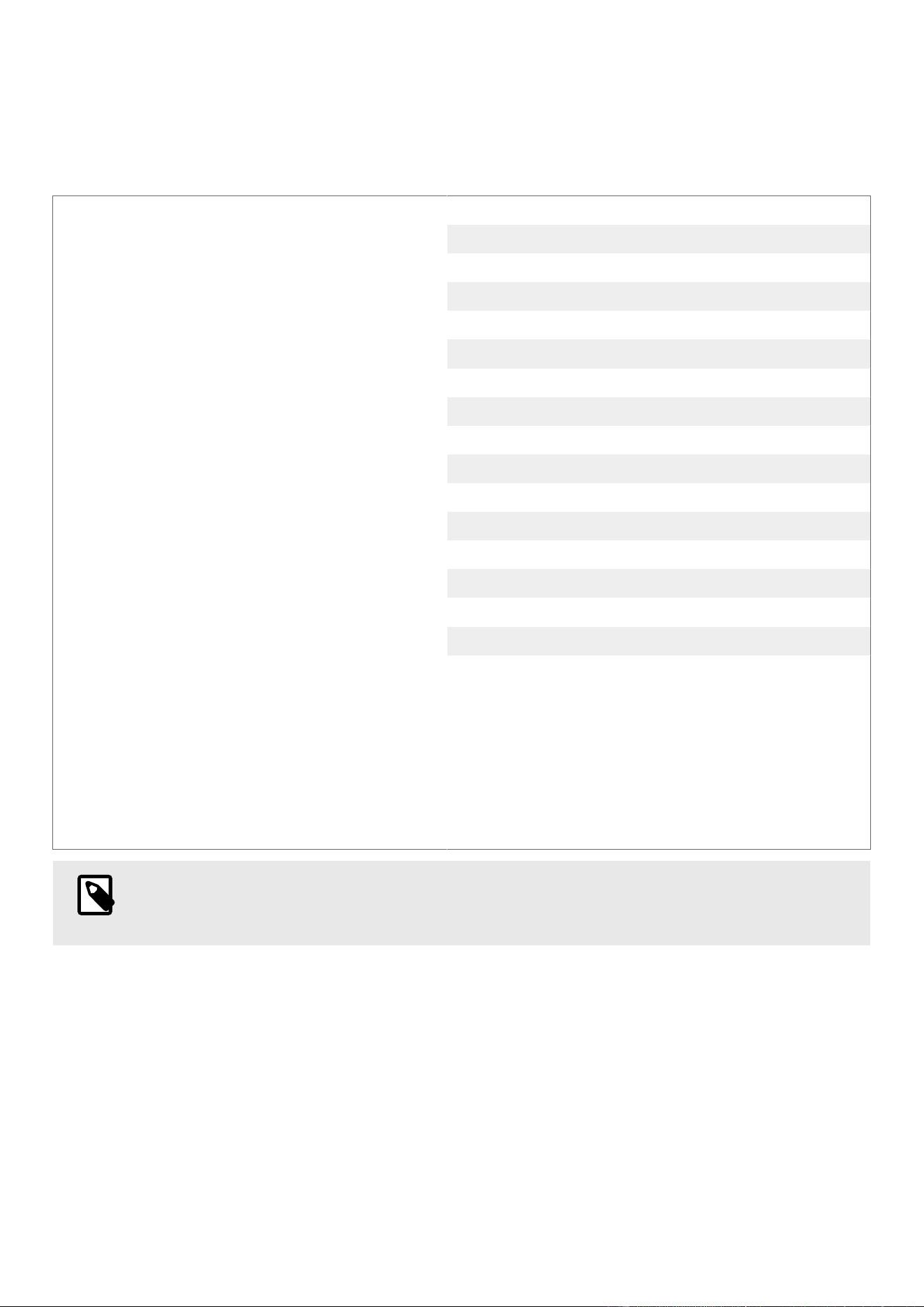
The following diagrams will help you understand the electronics in your Bigbelly Component. The ports used by your
exact Component will vary based on the conguration.
Table1.Solar Main Board Map: Smart Max, Sense Max, and Compost
1. Antenna
2. SIM Card
3. End of Drivetrain Sensor Port
4. Waste Interface Sensor Port
5. Auxiliary Port
6. Battery Cable Port
7. Motor Cable Port
8. ACS/Waste Interface Lock - Right Companion Port
9. ACS/Waste Interface Lock - Hub Port
10. ACS/Waste Interface Lock - Left Companion Port
11. Solar / AC Port
12. Right Companion Port
13. Waste Height Sensor Cable Port
14. Left Companion Port
15. ACS Reader Board Cable Port
16. Test Mode Button
17. LED Indicators
NOTE
Smart Max and Sense Max Stations congured for wall charging will still use the Solar-equipped Main
Board.
10
LABBB6UM - Rev. 8
July 2026

Table2.Non-Solar Main Board Map: Smart and Sense
1. Antenna
2. Battery Cable Port
3. Waste Interface Sensor Port
4. Right Companion Port
5. Waste Height Sensor Cable Port
6. Left Companion Port
7. SIM Card
8. Auxiliary Port
9. Test Mode Button
10. LED Indicators
11
LABBB6UM - Rev. 8
July 2026
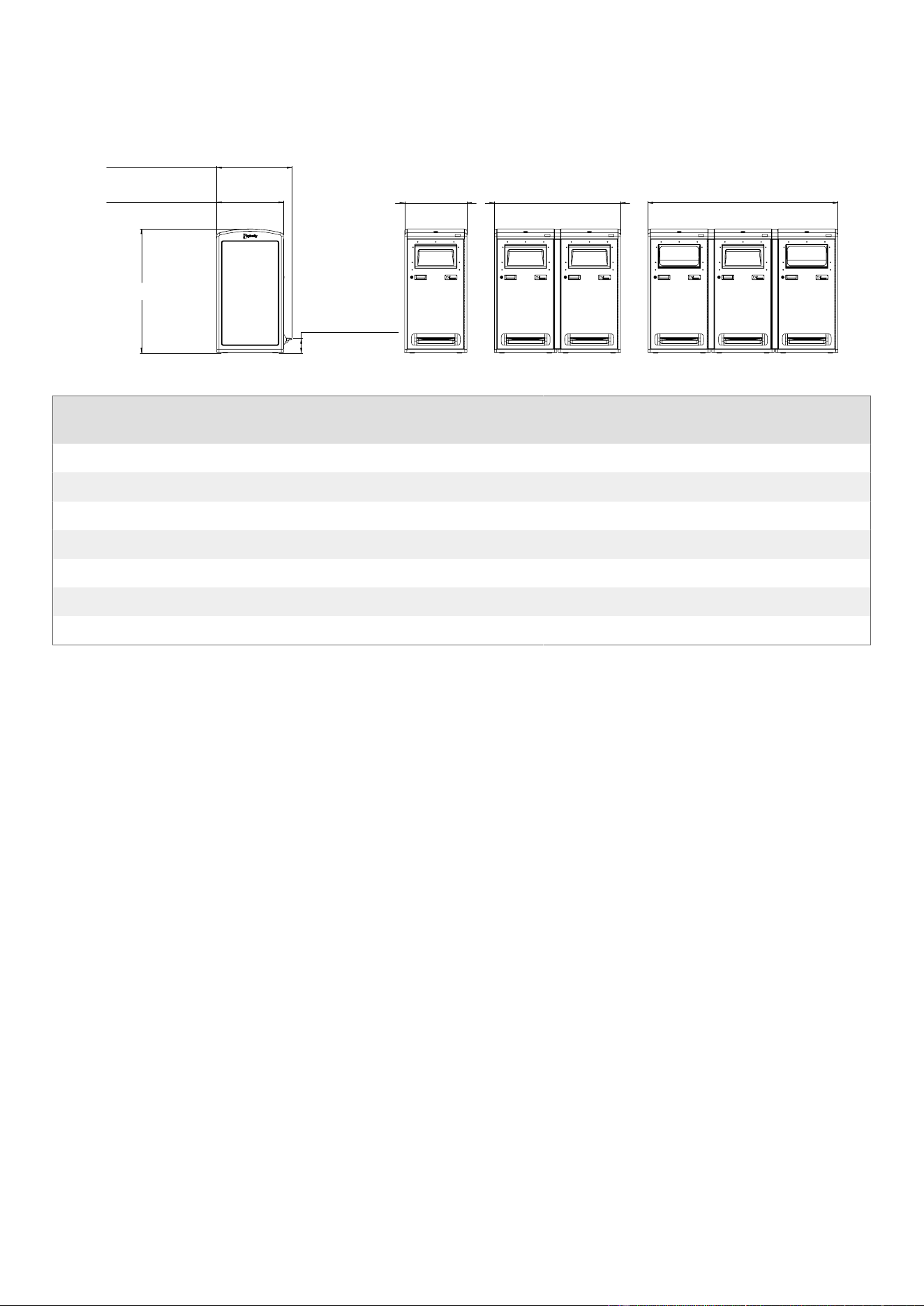
BB6 Product Specications
Figure1.Single, Double, and Triple Kiosk
26.8in [68.1cm]
30.2in [76.7cm]
5.7in [14.5cm]
49.8in [126.4cm]
76.2in [ 193.5cm]
25.0in [63.5cm]
50.6in [128.5cm]
Table3.Overall Product Dimensions and Specications
Attribute Smart Max &
Sense Max
Smart & Sense Element Compost
Width 25.0" (63.5 cm) 25.0" (63.5 cm) 25.0" (63.5 cm) 25.0" (63.5 cm)
Height 49.8" (126.4 cm) 49.8" (126.4 cm) 49.8" (126.4 cm) 49.8" (126.4 cm)
Depth 26.8" (68.1 cm) 26.8" (68.1 cm) 26.8" (68.1 cm) 26.8" (68.1 cm)
Handle Height 41.8" (106.2 cm) 41.8" (106.2 cm) 41.8" (106.2 cm) 41.8" (106.2 cm)
Weight 260 lbs (118 kg) 170 lbs (77 kg) 160 lbs (73 kg) 195 lbs (88 kg)
Shipping Weight 290 lbs (132 kg) 200 lbs (91 kg) 190 lbs (86 kg) 225 lbs (102 kg)
System Voltage 12V 6V N/A 12V
Recommended Clearance For Front Door And AC Adapter
Clearance is required in the front of the Station to allow for the Front Door's path of travel and in the back of the Station
to allow for an AC Adapter or AC Adapter Enclosure (if present). The relevant dimensions are listed below.
Figure2.Front Door Radius and Swing
Single Station Multi-Bin Kiosk
12
LABBB6UM - Rev. 8
July 2026

Figure3.AC Adapter and AC Adapter Enclosure Depth and Distance from Side Skin Exterior Surface
AC Adapter AC Adapter Enclosure
Waste Interface Options
The chosen Waste Interface will affect the the overall size and type of waste that can be deposited in a Station. See the
chart below to determine the dimensions and compatibility of each type.
Table4.Waste Interface Dimensions and Compatibility
Waste Interface
Type
Disposal Interface
Dimensions
Smart Max &
Sense Max
Smart &
Sense
Element Compost
Hopper 15"W x 5"H x 6"D
(381 x 127 x 152 mm)
Yes Yes Yes Yes
Chute 15"W x 7"H x 15"D
(381 x 178 x 381 mm)
Yes Yes Yes Yes
Open Faceplate 15.5"W x 8"H
(393 x 203 mm)
N/A Yes Yes N/A
Bottles & Cans
Faceplate
5" DIA.
(127 mm)
N/A Yes Yes N/A
Paper Faceplate 16.5"W x 3"H
(419 x 76 mm)
N/A Yes Yes N/A
Mixed Recycling
Faceplate
10.8"W x 8"H
(274 x 203 mm)
N/A Yes Yes N/A
Maximum Waste Volume
There are two bin sizes available for use with the Bigbelly system, depending on the Component type. See the chart
below to determine what is available for your Component. The size of bin used will affect the overall waste volume.
32 Gal (120 L) "Compactor Bin"
•
24” x 20.4” x 21.65” (609 x 518 x 549 mm)
•
Holds up to 32 Gal (120 L) of non-compacted
waste, and up to 150 Gal (568 L) of compacted
waste
47 Gal (178 L) "Non-Compactor Bin"
•
24.2" x 20" x 27.5" (615 x 508 x 699 mm)
•
Cannot be used with Compacting Stations
•
Will always hold up to 47 Gal (178 L) of waste
13
LABBB6UM - Rev. 8
July 2026
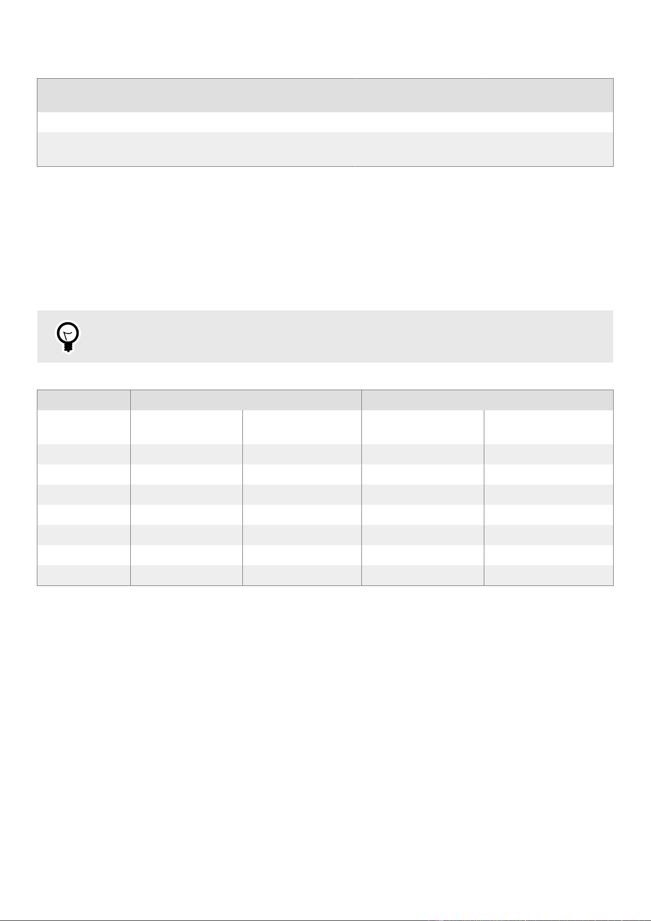
Table5.Inner Bin Compatibility
Bin Option Smart Max &
Sense Max
Smart & Sense Element Compost
32 Gal (120 L) Yes Yes, with Hopper Yes, with Hopper Yes, with Hopper
47 Gal (178 L) N/A Yes, with Chute or
Faceplate
Yes, with Chute or
Faceplate
Yes, with Chute or
Faceplate
Liner Bags For Your 6th Generation Stations
To help maintain a clean and odor-free Component, the use of Liner Bags is highly recommended. Use the chart below
to determine which Liner Bag is compatible with your bin type.
These extra-heavy-duty Liner Bags are made of linear low-density polyethylene (LLDPE). They are highly puncture- and
tear-resistant and are tall enough to ensure extra material for tying the Liner Bags closed when full.
The following items can be ordered through Bigbelly ([email protected]; +1.888.820.0300 Ext. 3) using the listed
Part ID, or can be sourced through a third party.
TIP
The use of incorrect bags may cause false alerts and lead to inaccurate collection data.
Table6.Liner Bag Specications
Compactor Bin (Short) Non-Compactor Bin (Tall)
Part ID BAGS-BBS-
CB4647
RBAGS-BBS-
RCB4647
BAGS-BBS-NCB4455 BAGS-BBS-RNCB4455
Thickness 2.5 mil 2.5 mil 1.6 mil 1.6 mil
Width 46" (117 cm) 46" (117 cm) 44" (112 cm) 44" (112 cm)
Height 47" (120 cm) 47" (120 cm) 55" (140 cm) 55" (140 cm)
Circumference 92" (234 cm) 92" (234 cm) 88" (223.5 cm) 88" (223.5 cm)
Color BLACK CLEAR GRAY CLEAR
Seal Type Flat Flat Star Star
Qty per Case 50 50 100 100
14
LABBB6UM - Rev. 8
July 2026

Safety Mechanisms
Safety mechanisms are in place to keep the user, service personnel, and maintenance personnel safe.
•
Closed Waste Interface (Hopper or Chute) - Designed to prevent access into the Component. The Closed Waste
Interface is sized for small litter to discourage illegal dumping. It is critical that the ClosedWaste Interface is kept
clear and free of debris to maintain functionality.
•
Waste Interface Lock - On Sense Max and Smart Max Stations with a Chute, the Waste Interface Lock engages prior
to compaction to prevent accidental injury. If the Chute cannot be locked (due to a jam or for any other reason), the
system will not allow the Ram to operate.
In other congurations, the Waste Interface Lock limits who can access the Waste Interface to deposit material. In
Compost Stations, it requires an app to unlock. For all other Stations, it serves as an optional security feature for
use during security events.
•
Front Door - Designed with a cut-off switch that prevents theRam from operating while theFront Door is open.
•
Front Door Release Cable - Enables release of the Front Door Lock from inside the Station.
•
Front Door Key - TheFront Door has an optional key lock that prevents unauthorized access into theComponent.
•
ACS Access Key - A key-card the size of a credit card that is provided for ACS-equipped Components to prevent
unauthorized access into the Component.
•
Top Door - The Top Door is held closed with two bolts that can only be accessed when the Front Door is open. Only
authorized personnel should open theTop Door.
Bigbelly ACS (Access Control System)
Bigbelly ACS is an exclusive cloud-based Access Control System for your Bigbelly smart waste deployment. It is fully
integrated into the system's electronics and the CLEANManagement Console and is 100% Solar-Powered, requiring no
additional batteries. Bigbelly ACS allows you to:
•
Grant, revoke, and manage Station access remotely, ensuring only authorized users can open Bigbelly Stations.
Access can be managed by groups of Stations, or by each Component individually.
•
Achieve unprecedented visibility into your waste collection operation. Increase accountability, improve oversight,
and enhance usage analytics.
•
Eliminate issues with lost or stolen keys, unauthorized door openings, and vandalized lock cylinders.
15
LABBB6UM - Rev. 8
July 2026

Site Selection
To minimize installation time, select a site for theStation prior to delivery. Mark the desired location so it is clear where
the installation crew needs to place theComponent.
The site for a BigbellyStation should be selected with ve main considerations:
•
Waste Volume: EachCompacting Component can hold far more waste than a traditional waste receptacle, reducing
the burden caused by peak periods of waste accumulation. As a result, the benets of theSmart Max and Sense
Max are maximized in high waste volume locations, or in remote areas. Non-compactor benets are maximized in
locations with lower waste volume.
•
Area Coverage: Space receptacles out to fully attain the benets of multiple collection points.
•
A Solid Surface: Concrete or mortared brick is best. The mounting surface should be as at as possible for
stability.For more information on mounting surfaces, contact your Account Manager, Distributor, or Bigbelly
Support.
•
Sunlight Overhead: Place solar-powered Components with an adequate amount of sky directly above. Do not
place Components under overhangs, awnings, heavy tree cover, etc. A site without open sky directly above
theComponentmay decrease battery life.
Non-Max and Non-Compost Components and indoor Components equipped with anAC Charging do not have this
restriction.
•
Adequate User Access & Clearance: Leave at least 36 in (92 cm) of clearance in the front, to allow for waste
disposal and collection. A clearance of 24 in (61 cm) behind theComponent is recommended in most cases, but an
indoor Component with an AC Charging Adapter may be installed close to a wall. The recommended curb set-back
is 24 in (61 cm).
Please contactBigbelly Support or your distributor with further questions about site selection.
Station Protection & Side-Walk Considerations
Below are a few other considerations to help protectComponents from vehicle strikes and to avoid interference with
other sidewalk uses.
•
Fire Hydrants: Fire code regulation (UniformFire
Code Section 1001.7.2) requires a 36 in (92 cm)
clearance around all hydrants.
•
Snow Plows [1]: Consider installing Components
24 in (61 cm) or more from the curb if the location
is frequently plowed and snow banks may be an
issue.
•
Bus Shelters [2]: Bus shelters often provide an ex-
cellent installation location. However, be mindful
not to block advertisements that appear on the side
panels of bus shelters.
•
Pedestrian Flow: Consider any pedestrian ow that
might be hindered or blocked.
16
LABBB6UM - Rev. 8
July 2026

•
Handicap Ramps and Crosswalks: Do not block handicap ramps or crosswalks. Ensure ample wheelchair
maneuverability around Stations, especially near ramps and crosswalks.
•
Crosswalk Buttons: If aComponent is installed next to a crosswalk button, ensure there is ample room for
wheelchair users to reach the button.
•
Light Poles or Other Structures [3]: Install Stations downstream of nearby poles or other structures to help
protect Components from possible vehicle strikes. Some structure examples are trafc lights, telephone or
sign poles, bicycle racks, large cement planters, etc.
•
Parking Meters [4]: Leave enough distance from parking meters to allow passengers room to open their doors
when exiting parked vehicles. If possible, center installations between double meters.
•
Loading Zones: Avoid installing near loading zones.
Large delivery trucks may damageComponents as
they back into loading zones or driveways.
•
Street Corners: Some busy street corners may be
ideal for waste collection, but keep in mind that
trucks may drive over curbs when making turns.
•
Ad & Messaging Panels: Allow maximum visibility
for advertisement and messaging panels.
17
LABBB6UM - Rev. 8
July 2026
Installation
Prior to Installation, please see the section regarding Site Selection (page 16) to ensure you are selecting a suitable
location for your Bigbelly Components.
It is highly recommended that outdoor Components are mounted to the ground to prevent theComponent from
being pushed over. TheComponents should be mounted directly to the ground and must be properly installed for the
warranty to be valid. For wooden oor surfaces, 3/8" lag bolts are recommended.
Once installation is complete, the Components must be activated and tested. Refer to Activation (page 32) in this
manual and the Test Guide (BB6) in CLEAN after initial installation is complete.
Receiving The Component
Each Component is shipped strapped to a pallet and encased in cardboard. Keys, mounting hardware, and any other
accessories, such as liner bags, are stowed in the Inner Bin.
To Identify the Component Type:
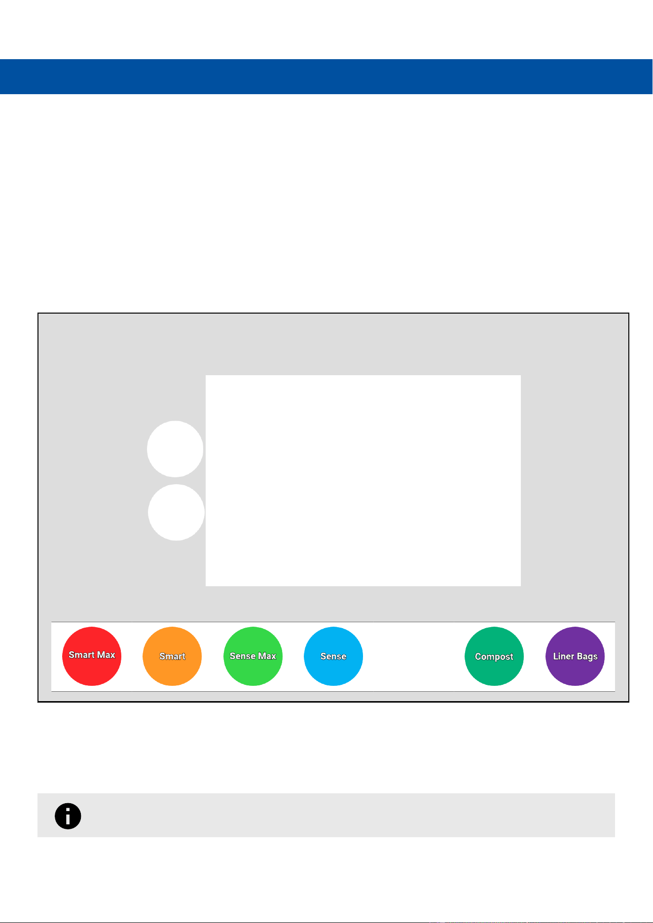
Locate the white Component Conguration Label and the colored sticker(s) on the packaging to determine what is
inside. Note that the second, purple sticker will only be present on packages containing Liner Bags.
Table7.Package Contents Color Key
Be sure to fully inspect the packaging before accepting the Component from the shipping company.If the packaging
appears to be damaged, unpack the Component and inspect it for damage prior to accepting the delivery.If there is any
visible damage, mark “damaged” on the freight bill and unpack the Component with the truck driver present.
Remove the straps, then remove the cardboard sleeve and packaging bag from the top of the Component.
If using a utility knife to remove the straps, be careful not to penetrate the cardboard sleeve.
18
LABBB6UM - Rev. 8
July 2026
Ensure that all contents of the Inner Bin are gathered before discarding the packaging materials.
Component Keys
Smart Max and Sense Max Sense, Smart, and Compost Element
•
One (1) Magnetic Fob
•
One (1) Front Door Key OR one (1) ACS Key
•
One (1) Front Door Key OR one
(1) ACS Key
•
One (1) Front
Door Key
The Component conguration will determine if the Front Door is Front Door Key enabled or ACS
enabled.
The Magnetic Fob that arrives with Smart Max and Sense Max Components will be used to initiate
Service Visits (Initiate a Service Visit (Compacting Components Only) (page 41)) and to run Manual
Compaction Cycles (Initiate a Manual Compaction Cycle (page 39)).
Transporting The Component
Components strapped to a pallet can be moved using a forklift or pallet jack according to the following procedure.
Transport a Component While on a Pallet
1. Adjust the forks of the forklift to as wide as will t within the pallet.
2. Ensure the forks are completely inserted into the pallet before lifting.
3. Transport the Component to the appropriate location.
Avoid sudden movements while the Component is lifted. Sudden or jerky moments could cause
the Component to fall off the pallet.
4. Once in the desired location, carefully lower the Component completely to the ground.
Removing The Component From The Pallet
Each Component is shipped strapped to a pallet. Once the straps and cardboard packaging have been removed, follow
these steps to remove it from the pallet:
1. Open the Front Door by pulling the orange Front Door Release Cable Tie, pictured below, and conrm that the serial
number on the packaging correctly matches the serial number on theComponent (located beneath the LED lights).
Report any errors to your distributor orBigbelly Support.
19
LABBB6UM - Rev. 8
July 2026
Do not remove the orange Front Door Release Cable Tie until installation and testing is complete.
2. Remove the Inner Bin and close the Front Door. Retrieve the keys, mounting hardware, and any other accessories
from the Bin. Note: if Liner Bags were included on the order, these will be inside one of the Bins.
3. Carefully tilt the Component to the side and walk it off either side of the pallet, then slide or kick the pallet out from
beneath. This is easiest with two people.
Do not forget to remove the blue shrink wrap, shown below, from the top of the Component.
Transporting The Component Without A Pallet
Once it has been removed from the pallet, the Component should only be moved with a hand truck. The hand truck
must have safety straps and a load capacity of at least 400 pounds (182 kg). To protect the powder coat nish on
the Component, use padding between the straps, the Component, and the hand truck. Use the following procedure to
transport the Component without a pallet.
Never lift the Component from the front or sides, as this can damage the Waste Interface, Foot Pedal,
or Side Skins. Always lift from the back.
Transport a Component (Without a Pallet)
1. If the hand truck does not have a rubber or vinyl protective coating, wrap padding around the Component to
prevent it from being scratched during transport.
2. Wrap the hand truck's safety strap around the Component, and tighten until the Component is secured. Be sure to
wrap the safety strap below the Waste Interface.
3. Ensure the load plate of the hand truck is completely beneath the Component before lifting.
4. Upon lifting, chock the wheels to prevent the hand truck from rolling prematurely.
5. Transport the Component to the appropriate location.
6. Once the in the desired location, reverse the lifting method to gently lower the Component to the ground.
20
LABBB6UM - Rev. 8
July 2026
Installing And Securing The Component
Whenever possible, mount Components directly to the ground. For Components that are to be placed on bricks or on
a slab smaller than the base, Mounting Plates are available. Contact your distributor or Account Manager for more
information, or reach out to Bigbelly Support at +1.888.820.0300 Ext. 3.
Installation Tools & Materials
•
Power Drill
•
Hammer Drill
•
Diagonal Cutter
•
1/2" Socket (13 mm)
•
5/16" Socket (for multi-bin kiosks only) (8 mm)
•
9/16" Hex Bit Socket (14 mm)
•
3/8" Masonry Drill Bit (9.5 mm), at least 5" (12.7 mm)
long
•
Front Door Key or ACS Key (provided)
•
Magnetic Fob (provided) for testing Compaction
•
Anchor Screws (provided)
•
Stabilizing Bolts (provided)
•
#10 Screws (provided)
•
Mobile Phone (iOs or Android) for adding Stations to
CLEAN
The following instructions are for the direct-mount method. To install and secure a single Component, see
below (page 21). To install and secure a multi-bin kiosk, skip to Install and Secure a Multi-Bin Kiosk (page 22). For
a general overview, see the Double Station Installation video.
Install And Secure A Single Component
1. Place your Component where you would like it
secured and installed. Remove the blue plastic lm
from the Top Bubble.
2. Open the front door and remove the Inner Bin if you
have not already done so.
3. Tighten/loosen the Stabilizing Bolts (circled in red)
with a 1/2" Hex Bit Socket until the Component is
leveled and stable.
4. Drill (4) pilot holes through the holes (circled in
blue) inside the Molded Base and into the mounting
surface using a Hammer Drill and 3/8" Masonry Drill
Bit.
• Minimum hole depth in the concrete is 2" below
concrete surface (or roughly 4.75" below the
interior oor).
5. Anchor the Component directly to the surface by
driving the (4) Screw Anchors provided with the
Component into the surface using a Power Drill and
9/16" Hex Bit Socket.
6. Conrm the Screw Anchors are fully seated and not
proud of the Component oor.
7. Replace the Inner Bin. Physical installation is
complete.
Red = Stabilizing Bolts; Blue = Screw Anchor
Once the Component is properly installed, it must be activated and tested. Refer to
Activation (page 32) and the Test Guide (BB6) for the necessary procedures. If activation and testing
are not performed, the Component may not function.
21
LABBB6UM - Rev. 8
July 2026
Do not remove the orange Front Door Release Cable Tie until installation and testing is complete.
Install And Secure A Multi-Bin Kiosk
1. Place the Components where you would like them secured and installed. Remove the blue plastic lm from the
Top Bubbles.
2. Open the Top Door.
a. Open the Front Door by pulling the orange Front Door Release Cable Tie.
b. Locate the two 5/16" Screws in the Top Door tabs, circled below left. They must be removed with a Power Drill
tted with a 1/2" Socket before the Top Door can be opened.
Keep these Screws to re-secure the Top Door once the work is completed.
c. Lift the Top Door open. The door will be propped open by the Gas Spring, pictured above right.
3. Remove the Inner Bins if you have not already.
4. If the Kiosk contains Companions, connect the Companion cabling.
If the Kiosk does not include a Companion, skip to Step 5.
How to Connect Companion Components
LEFT VS RIGHT
If the Companion Component is placed to the LEFT of the
Hub [C], it is a "Left Companion" [A].
If the Companion Component is placed to the RIGHT of the
Hub [C], it is a "Right Companion" [B].
22
LABBB6UM - Rev. 8
July 2026

a. Retrieve the Companion Extension Cable (ELCBB60019) from the Component packaging, and plug it into the
corresponding Left [1] or Right [2] Companion port on the Main Board.
Solar Main Board Non-Solar Main Board
b. Route the Companion Extension Cable (ELCBB50019) according to the table (page 23) below. Place it into
the indicated Cable Clips. It will be passed through the grommet in the following step.
Table8.Companion Extension Cable(ELCBB60019) Routing
Main Board
Type
Routing for LEFT
Companion
Routing for RIGHT Companion
Solar
Place in one indicated Cable Clip Place in three indicated Cable Clips
Non-Solar
Place in one indicated Cable Clip
Place in two indicated Cable Clips
23
LABBB6UM - Rev. 8
July 2026
c. Feed the Companion Extension Cable (ELCBB60019) through the grommet, and plug it into the Companion
Sensor Cable (ELCBB50010) already protruding from the Companion Component grommet.
Note: example shows connection for LEFT Companion.
Feed Companion Extension Cable (ELCBB60019) through Grom-
met
Plug into Companion Sensor Cable (ELCBB50010)
•
If the Companion Component does not have an ACS Door Lock or a Waste Interface Lock, this
completes the connection.
•
If the Companion Component does have an ACS Door Lock or Waste Interface Lock, proceed as
follows:
d. Retrieve the ACS WIL Extension Cable (ELCBB50014) from Component packaging, and plug it into the
corresponding Left [1] or Right [2] ACS/WIL Companion port on the Solar Main Board.
24
LABBB6UM - Rev. 8
July 2026
e. Route the ACS WIL Extension Cable (ELCBB50014) according to the table (page 25) below. Place it into the
indicated Cable Clips. It will be passed through the grommet in the following step.
Table9.ACS WIL Extension Cable(ELCBB50014) Routing
Routing for LEFT Companion Routing for RIGHT Companion
Place in one indicated Cable Clip
Place in seven indicated Cable Clips
f. Feed the ACS WIL Extension Cable (ELCBB50014) through the grommet, and plug it into the ACS WIL Cable
(ELCBB60013) already protruding from the Companion Component grommet.
Note: example shows connection for LEFT Companion.
Feed ACS WIL Extension Cable (ELCBB60014) through grommet Plug into ACS WIL Cable (ELCBB60013)
This completes the connection.
Verify all connections have been made before proceeding. Doing this later will require
disassembly.
25
LABBB6UM - Rev. 8
July 2026

5. Install the Connecting Plate via slots in the Top Plate to verify the multi-bin Kiosk is aligned and spaced properly.
Adjust as needed. Do not install the screws yet.
6. Choose a Component to install rst. If this is a three-Component Kiosk, the middle Component should be
installed rst. If this is a two-Component Kiosk, the order does not matter.
7. Tighten/loosen the Stabilizing Bolts (circled in red) on the rst Component with a 1/2" Hex Bit Socket until the unit
is leveled and stable.
Red = Stabilizing Bolts; Blue = Screw Anchor
8. Drill (4) pilot holes through the holes (circled in blue) inside the rst Bigbelly and into the mounting surface using
the 3/8" Masonry Drill Bit and your Hammer Drill.
• Minimum hole depth in the concrete is 2" below concrete surface (or roughly 4.75" below the interior oor).
9. Anchor the rst Component directly to the surface by driving the (4) Screw Anchors provided with the Station into
the surface using the Power Drill and 9/16" Hex Bit Socket.
10. Conrm the following:
a. Screw Anchors are fully seated and not proud of the Component oor.
b. The tops of all Components in the Kiosk are aligned with each other.
c. The Rear Panels of all Components are in plane with each other.
Tighten/loosen the Stabilizing Bolts as needed to make the Components level and stable.
11. Repeat Step 8 through Step 10 for the second unit and third unit (if applicable).
26
LABBB6UM - Rev. 8
July 2026

12. Fasten the Kiosk Connectors to the Components using the #10 screws provided (Qty. 8). Install using a Power Drill
and 5/16" Hex Bit Socket.
Kiosk Connector secured by screws (circled)
13. Install the front and back Fascia Strips by aligning the strips and then sliding them down to hook into the slots.
Ensure the Fascias are fully seated.
27
LABBB6UM - Rev. 8
July 2026

14. Slide the Tombstone into place and fasten it with two #10 Screws. Tighten to 22 in-lbs.
Tombstone [1] and Front Fascia Strip [2] secured by screws (circled)
Close the Top Doors to ensure the Tombstone is fully seated.
15. Replace the Inner Bin. Physical installation is complete.
Once the Component is properly installed, it must be activated and tested. Refer to
Activation (page 32) and the Test Guide (BB6) for the necessary procedures. If activation and testing
are not performed, the Component may not function.
Do not remove the orange Front Door Release Cable Tie until installation and testing is complete.
28
LABBB6UM - Rev. 8
July 2026

Conguring Your Compactor For Indoor Use
If your Component is dual congured for both indoor and outdoor use, and you would like to use it indoors, follow the
steps below:
Install the AC Adapter
1. Unplug theSolar Panel Cable from the "Solar/AC Power" port [2] and connect theAC Adapter Cable instead.
2. Locate the two#10 Screws on the bottom right of the Rear Panel and remove them. Set them aside for use in the
next step.
29
LABBB6UM - Rev. 8
July 2026

3. Align the AC Adapter Enclosure with the holes left on the rear of theComponent, and securely mount theAC
Adapter Enclosure using the previously removed#10 Screws through the holes circled in red.
The AC Adapter Enclosure protects the AC Adapter from damage or inadvertent disconnection
from the Component.
4. Plug the AC/DC Converter into the Cable Jack (circled in green above and below, right). If desired, plug the AC/DC
Converter into an extension cord (not included).
An extensioncord is not included. The design intention is to plug the AC/DC Converter directly
into an outlet. However, an extension cord may be used if desired or needed.
30
LABBB6UM - Rev. 8
July 2026
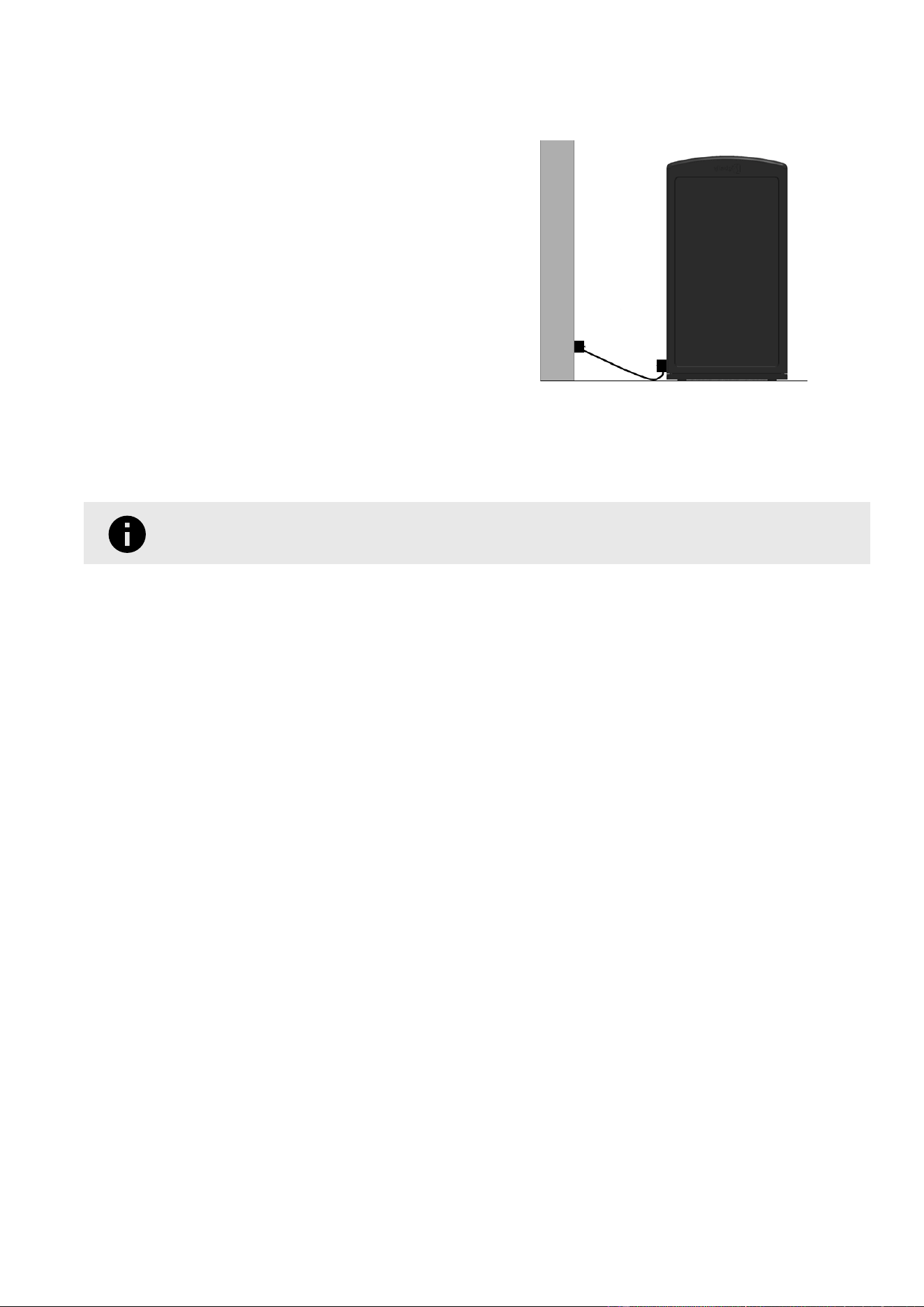
5. Once the AC Adapter Enclosure is securely installed (left image below), the AC/DC Converter or extension cord can
be plugged into a power outlet (right image below).
6. If using an extension cord, coil the AC/DC Converter [1] and end of the extension cord [2] up into the Enclosure, as
shown below left. Otherwise, simply coil any excess length of the AC/DC Converter into the Enclosure. Latch the
AC Adapter Enclosure closed. The latch is located in the blue rectangle, below right. Be careful not to pinch the
cables.
If desired, secure the AC Adapter Enclosure closed using a padlock or Zip Tie in the hole circled in
red, below right.
31
LABBB6UM - Rev. 8
July 2026

Activation: Turning On Your Components
All Components are shipped with the Battery disconnected. Once theComponenthas been installed, connect the
Battery to theMain Board to power on the Component (does not apply to Companion or Element Components).
Installation should take place soon after receiving theComponent. If theComponents were shipped more than six
months prior to installation, theBattery voltage may drift below a safe operating level. This can shorten the life of
theBattery upon installation. The LED Operations Guide can help you determine whether the Battery is low.
1. Open the Top Door
a. Open theFront Door using the Front Door Key or ACS Access Key.
b. Locate the two 5/16" Screws in the Top Door tabs, circled below left. They must be removed with a Power Drill
tted with a 1/2" Socket before the Top Door can be opened.
Keep these Screws to re-secure the Top Door once the work is completed.
c. Lift the Top Door open. The door will be propped open by the Gas Spring, pictured above right.
2. Connect Power
a. Plug the Battery Cable into the "Battery" port on the Main Board.
b. If the Component has a Solar Main Board, conrm that the Solar Panel Cable or AC Adapter Cable is plugged
into the "Solar/AC Power" port.
Figure4.Solar Main Board Battery Port [1] and
Solar/AC Power Port [2]
Figure5.Non-Solar Main Board Battery Port
32
LABBB6UM - Rev. 8
July 2026

3. Check the LED indicators at the front of the Component to verify successful power-up. The LED panel will display
a solid Green, Yellow, and Red light for 10 seconds before reverting to a ashing Green, Yellow, and Red while the
door is open. If the Component is ACS-enabled, a rising, three-tone melody will also sound.
Solid LEDs for the rst 10 seconds. Flashing LEDs after 10 seconds
4. The Component is now powered on and ready for testing.
Testing Your Component
Once the Component has been installed and powered on, run any applicable tests to ensure it is operating as expected.
Tests may vary depending on the Component conguration. If the Component has an ACS Front Door Lock, the Lock
must be tested before the orange Front Door Release Cable Tie is removed.
See the Test Guide (BB6) in CLEAN for a complete set of instructions and for help determining which tests are
appropriate. Possible tests are:
•
ACS Front Door Lock Tests
•
Various Sensor Tests
•
Waste Interface Lock Test
•
Manual Compaction Test
Removing The Front Door Release Cable Tie
Once the Component has been installed and successfully tested, the orange Front Door Release Cable Tie must be
removed before the Component is left unattended. If the Front Door Release Cable Tie is not removed, anyone will have
access to the Component at any time.
To Remove the Front Door Release Cable Tie:
1. Open the Front Door with the Front Door Key or ACS
Access Key.
2. Locate the orange Front Door Release Cable Tie on the
bottom corner of the Front Door.
3. Using Diagonal Cutters (Wire Snips), cut and remove the
Front Door Release Cable Tie.
33
LABBB6UM - Rev. 8
July 2026

CLEAN Mobile Install Procedure
CLEAN-enabled Stations must be set up in CLEAN before you can begin managing them. This step is most easily
performed during physical installation. Prior to installation, ensure you have received a CLEAN username and
password, and that the CLEAN Mobile app has been downloaded to your mobile device.
This example shows installation of a double Station, where the leftmost Component is congured for bottles and cans.
Select the gear icon in the upper right corner to exit the installation at any time. CAUTION: exiting the
installation before completion deletes all information entered for that Station.
1. Within the CLEAN Mobile application, select the Install button (circled in green below left).
2. Select the number of Components in the Station, then select NEXT to continue.
34
LABBB6UM - Rev. 8
July 2026

3. Open the Front Door of each Component. Select SCAN BARCODE, and scan the barcode of the left Component.
Once the barcode has been scanned, select NEXT to continue.
The barcode is located to right of the LEDs
4. Select the intended Waste Stream for this Component, then select NEXT to continue.
5. Select SCAN BARCODE, and scan the barcode of the right Component. Select NEXT, followed by the intended
Waste Stream for this Component. Select NEXT again to continue.
6. Congure the location. The blue area indicates your current GPS location. Use the cross-hairs to select the
Station's proper location on the map, then select INSTALL HERE.
35
LABBB6UM - Rev. 8
July 2026
7. Enter a brief Station Description to specify the location. For example, "Main St & 1st Ave" or "Main Street, in front
of gas station." Once a description has been entered, select ADD PHOTO.
8. Take pictures of each installed Component in the Station. Be sure to capture:
Front Left Side Rear Right Side Top Open
Note: Once the rst photo has been added, additional photos may be taken.
When uploading, label each photo according to its view (Front, Left Side, Right Side, Rear, Top Open). After all
photos have been added, select NEXT to continue.
9. Select which Groups the installation should be added to. Multiple groups may be selected as shown below left.
Select NEXT to continue.
36
LABBB6UM - Rev. 8
July 2026

10. A conrmation page will appear. Ensure all of the presented information is correct, including the serial numbers,
location, and listed groups. Once satised, select NEXT.
Note: the Groups list has a scrolling function, which may not be
immediately apparent
11. Once the installation is conrmed, a map showing the Station location will appear. Select the "Add Another Station"
button at the bottom of the page to install another Station, or select the gear icon in the upper right corner to be
given the choice of exiting the installation.
37
LABBB6UM - Rev. 8
July 2026

Operations
LED Indicators
All Components except Elements include a set of three LED lights: one green, one yellow, and one red. The pattern of
these lights will change to indicate the state of the machine. Both routine states and error states may be indicated by
the LEDs.
Many LED patterns are described throughout this document. For a centralized list of all possible LED patterns and their
meaning, see the LED Operations Guide (BB6) in CLEAN.
Compacting Stations (Sense Max And Smart Max)
Smart Max and Sense Max Components are ready for use once they are properly installed and tested. If the
Component is a "Smart," it should also be set up in CLEAN.
Users open the Waste Interface and place their litter into
the Component. When the Waste Interface closes, the
contents fall into the Inner Bin. When the waste reaches a
pre-determined height, a Compaction Cycle is triggered.
During a Compaction Cycle, Smart Max and Sense Max
Components activate the motor which lowers and raises
the compaction Ram. The Ram moves down to compact
the waste, stops, and returns to the raised “home”
position. The Ram remains in the raised “home” position
until a Compaction Cycle is triggered again.
Trash Height Sensors in the Side Walls detect the level of trash and are
responsible for initiating automatic compactions
If the Front Door is opened at any point during a Compaction Cycle, the Ram will immediately stop and will remain
stopped until the door is closed. To resume normal operation, close the Front Door.
For Smart Max and Sense Max Stations with a Chute, the Waste Interface Lock will lock the Chute prior to the
Compaction Cycle and will release the Chute when the Compaction Cycle is completed.
Once the bin has become full, the LED panel will display a ashing red light to indicate that the waste should be
collected. If the Station is active in CLEAN, a fullness notication will also be generated.
Manual Compaction Cycle (Smart Max And Sense Max Only)
Activate a Manual Compaction Cycle to ensure the Compactor is ready to use.
It takes approximately one minute for the Compactor to complete a Manual Compaction Cycle. If the Height Sensors
are blocked by waste, the Compactor may automatically run up to ve Compaction Cycles to clear whatever is blocking
the Height Sensors.
38
LABBB6UM - Rev. 8
July 2026

Initiate a Manual Compaction Cycle
The Manual Compaction Test can be initiated on the Smart Max and Sense Max at any time, except
during Test Mode
1. With the Front Door closed, open the Waste Interface.
2. Locate the recessed area (shown below right) on the left, inner, top surface of the Component. The recessed area
(circled in blue in the cross-sectional image below left) is located above the Waste Interface opening and below
the Component LEDs.
3. Place the Magnetic Fob against the raised circle until a solid green LED appears, then remove the Magnetic Fob
and hand from the Component and close the Waste Interface. During the Compaction Cycle, some noise will be
produced by the compactor, and the solid green LED will stay lit.
Chute-equipped Components are unable to compact if the Chute remains open. Close the Chute
within ve seconds of initiating the Cycle to allow the Waste Interface Lock to engage. Once the
Compaction has begun, pull on the Waste Interface to conrm that it has locked.
4. Once the Manual Compaction Cycle completes successfully, the solid green LED will transition to a blinking green
LED to indicate that it is not full or to a blinking red LED to indicate that it is full.
5. If any of the following occur, check all wiring and connections (including the Fuse) and initiate another Manual
Compaction Cycle.
• The Manual Compaction Cycle does not complete
• The Waste Interface Lock fails to engage (Chute-equipped Components only)
• The solid red LED turns on during or after the Manual Compaction Cycle
• The Component restarts
If any of these failures persist, contact Bigbelly Support at +1.888.820.0300.
39
LABBB6UM - Rev. 8
July 2026

6. If this is a new installation and the Compaction completes successfully, the Component is ready for use.
Non-Compacting Stations (Sense And Sense Max Only)
Non-compacting Stations are ready for use once they have been properly installed and activated in CLEAN (Smart
Stations only). Users place litter or recycling material into the Component via the Waste Interface or the Faceplate.
The Top-Down Height Sensor in the Component measures the level of waste. Once the bin is full, the LED panel will
display a ashing red light to indicate that the waste should be collected. If the Station is active in CLEAN, a fullness
notication will also be generated.
The Top-Down Height Sensor in the Top Plate detects the level of waste in the bin
Compost Stations
Compost Stations are ready for use once they have been properly installed and activated in CLEAN. Once active in
CLEAN, the Stations will also become available in the end user's Compost app. The default state of the Waste Interface
is in the locked position. When a user wants to deposit materials into the Component, they must unlock the Waste
Interface via the Compost app. Once the materials have been deposited, the Waste Interface returns to the locked
state.
The Top-Down Height Sensor in the Component measures the level of waste. Once the bin has become full, the LED
panel will display a ashing red light to indicate that the waste should be collected, and the Component will become
unavailable in the Compost app until the bin has been emptied. A fullness notication will also be generated.
Element Stations
Element Stations are ready to use as soon as they have been installed. Users place litter or recycling materials into the
Component via the Waste Interface or the Faceplate. Element Stations have no electronics to indicate when they are
full and must be physically checked.
40
LABBB6UM - Rev. 8
July 2026

Initiating A Service Visit (Compacting Components Only)
AService Visitmay be initiated on any CLEAN-enabled, Compacting Component prior to any non-collection visit. This
prevents any door openings during the visit from being counted as a collection and impacting the account efciency
rating in CLEAN.
The Service Visit can only be initiated on a Hub, but will include any Companions that are part of the Station Kiosk. The
Service Visit will clear automatically once the Front Door has been securely closed.
Follow the procedure below any time a door is opened during a non-collection visit or after the Station has been power
cycled to ensure the door opening event is ignored and does not affect collections data.
Initiate a Service Visit (Compacting Components Only)
1. Open the Front Door using the Front Door Key or ACS Access Key. All three LEDs (green, yellow, and red) will ash.
2. Locate the recessed area (shown below right) on the left, inner, top surface of the Component. The recessed area
(circled in blue in the cross-sectional image below left) is located above the Waste Interface opening and below
the Component LEDs.
For this procedure, the Front Door must be open.
3. Place the Magnetic Fob against the raised circle (depicted above, right) until only the green and red LEDs ash and
the yellow LED stops ashing.
4. Service the Station.
5. To exit Service Mode, rmly close the Front Door.
41
LABBB6UM - Rev. 8
July 2026
Collections And Fullness
The following section on Fullness and Age Thresholds applies to CLEAN-Enabled Components only:
Fullness Threshold & Age Threshold
The Component will indicate the waste is Ready to Collect once either the Fullness Threshold or the Age Threshold is
exceeded, whichever occurs rst.
The Fullness Threshold controls how full a bin is allowed to become before the Component indicates it is Ready to
Collect.
• The default Fullness Threshold for a Max Component is set to 60%.
• The default Fullness Threshold for a Non-Compacting Component is set to 80%.
The Age Threshold controls the maximum time allowed to pass between collections before the Component
indicates it is Ready to Collect.
• The Age Threshold is left disabled by default.
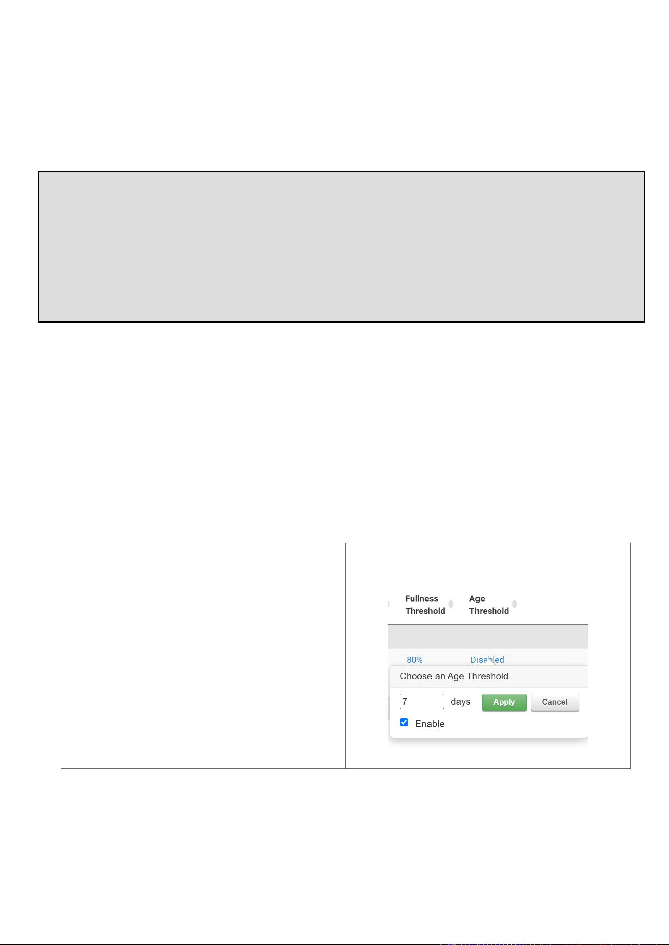
Both thresholds can be adjusted in CLEAN by an account Administrator.
1. Log into CLEAN. Navigate to the Assets Page.
2. On the Assets Page, congure either threshold for the Component. Changes will take effect during the
Component's next communication with CLEAN, which may take up to 12 hours.
The Fullness Threshold can be adjusted to twenty
(20) percentage increments (20%, 40%, 60%, 80%, or
100%).
The Age Threshold can be adjusted in daily incre-
ments between one (1) and sixty (60) days.
Liner Bags
The use of Liner Bags is highly recommended to keep your Stations fresh. Always ensure that you are using the
appropriately sized Liner for your bin. See Liner Bags for your 6th Generation Stations (page 14) in the "Introduction:
BB6 Product Specications" section of this Manual for the appropriate liner specications.
42
LABBB6UM - Rev. 8
July 2026

Using incorrect Liner Bags or not using the Inner Bin Sleeve with a Non-Compactor Bin may cause
false alerts and lead to inaccurate collection data.
How to Install Liner Bags in Your Components
1. Conrm that you have purchased the correct Liner Bags (page 14).
2. Open the Liner Bag completely by lling it with air.
3. Insert the opened Liner Bag into the Inner Bin.
4. Fold the top of the Liner Bag over the top edge of the Inner Bin while pushing the Liner Bag against the inside of
the Inner Bin. This will help keep the Liner Bag away from the center of the Inner Bin.
Ensure that no air is trapped beneath the Inner Bin. An inated Liner Bag may be misinterpreted as
fullness by Non-Compacting Components.
5. If this is a Compacting unit, conrm that the Liner Bag is not bunched up on the sides, which could block the
Height Sensors in the Side Walls.
6. If this is a Non-Compacting Component, proceed to installing the Inner Bin Sleeve.
Installing An Inner Bin Sleeve (Non-Compactor Bins Only)
Non-Compactor Components use a Top-Down Height Sensor to detect the waste fullness level within the Inner Bin. The
Inner Bin Sleeve improves the accuracy of Height Sensor readings by holding the Liner Bag ush against the sides of
the Inner Bin, eliminating possible interference with the Height Sensor.
Failure to install the Inner Bin Sleeve in a Non-Compactor Bin may result in inaccurate or premature waste fullness
readings. Follow the procedure below to properly install the Inner Bin Sleeve.
Install the Inner Bin Sleeve in a Non-Compactor Bin
1. First install the Liner Bag, taking care to press out as much air from between the Inner Bin and Liner Bag as
possible, such that the Liner Bag is ush with the Inner Bin.
43
LABBB6UM - Rev. 8
July 2026

2. Align the Inner Bin Sleeve above all four sides of the Inner Bin and carefully slide the Inner Bin Sleeve down into the
Inner Bin. The Inner Bin Sleeve should be fully seated in the Inner Bin, as shown below.
Ensure the Liner Bag does not slip into the Inner Bin while inserting the Inner Bin Sleeve.
Above left shows how to insert the Inner Bin Sleeve. Above right shows the Inner Bin Sleeve properly installed.
Waste Removal & Routine Visual Inspection
A ashing red LED indicates when it is time to remove waste from the Component. Refer to LED Indicators for more
information regarding the LEDs.
Always ensure that you are using the appropriately sized liner for your bin. Liner specications can be found in the
Product Specications (page 12) portion of this Manual.
Waste Removal Procedure
1. Open the Front Door with the Front Door Key or the ACS Access Key.
2. Push any loose waste into the Inner Bin and remove the Inner Bin from the Component.
3. Perform a Visual Inspection. A Visual Inspection should be performed each time waste is removed. Refer to the
following checklist to ensure an effective inspection:
•
Ensure no debris has fallen behind the Inner Bin
•
Ensure the Height Sensors are clear of debris
•
Remove any debris in or around the Waste Interface or Faceplate area
4. Remove the bag or dump the contents of the Inner Bin directly into the truck. If this is a Non-Compacting
Component, remove the Inner Bin Sleeve rst.
Be sure to follow proper ergonomic procedures for waste removal. The average weight of
the Inner Bin when full is 25-30 pounds (11-14 kg), but weight may vary depending on the
waste mix and the Fullness Threshold or Age Threshold setting (see Fullness Threshold & Age
Threshold (page 42) for details).
5. Replace the bag, following the procedures outlined above (page 42). If this is a Non-Compacting Component,
ensure that no air has become trapped beneath the Liner Bag and that the Inner Bin Sleeve is re-installed.
44
LABBB6UM - Rev. 8
July 2026
6. Clean the Component if necessary. Odors exist when layers of food collect on the Waste Interface and Ram. Keep
the Component clean and free of odor by regularly wiping off any buildup with an approved product from Approved
Cleaning Products (page 52).
TIP
An Odor Mask Kit can help with odor. Installation is simple, and the scented discs are easy to
replace. Contact your distributor or Bigbelly to order.
7. Return the Inner Bin to the interior of the Component. Push it all the way to the back, and ensure the Liner Bag does
not block the Front Door Latch or the Height Sensors in the Side Walls if this is a Compacting Component.
If the Inner Bin does not slide completely into the Component, check for stray waste that may
have fallen behind the Inner Bin.
8. Securely shut and lock the Front Door. Verify operations are normal as indicated by a blinking green LED (Smart
Max, Sense Max, and Compost) or by unlit LEDs (Smart and Sense).
Failure to securely shut and lock the Front Door could result in damage to the component and
possible harm to users. If the Front Door is not properly secured, the Component will stop
compacting and will generate an alert in CLEAN (if CLEAN-equipped).
Battery Overview
Each powered Component will identify when Battery replacement is required. If the Battery requires a charge
(Compacting or Compost Components only) or needs to be replaced, the appropriate alert will be sent to CLEAN.
If the Component is not CLEAN-enabled, the LED panel will also indicate whether the battery has become low or
needs to be replaced. Reference the LED Operations Guide (BB6) to determine whether the LED panel is reporting a
battery-related issue.
Rechargeable Battery Overview
Rechargeable 12V Batteries are used in the Sense Max, Smart Max, and Compost. The Sense Max and Smart Max use
a 28Ah Battery while the Compost uses a smaller 18Ah Battery. These Batteries are designed to be charged regularly
by either the Solar Panel (outdoor Stations with a clear view of the sky only) or by the AC Adapter (indoor Stations or
Stations with poor access to the sun). The Solar Panel or the AC Adapter must be plugged into the Main Board in order
to charge the Battery.
If the rechargeable Battery goes longer than three (3) months without charge from either the Solar
Panel or by the AC Adapter, the Battery will lose capacity and may fail at an accelerated rate.
Non-Rechargeable Battery Overview
Non-rechargeable Batteries, made of up to four (4) 6V lantern batteries, are used in the Sense or Smart. The
Component slowly draws power from the Battery until it is depleted.
Replacing A Battery
To replace a Battery, refer to the procedural documents hosted on the CLEAN Support Page, or reach out to Bigbelly
Support for more information.
Preparing A Component For Storage
Certain steps must be taken before placing a Component in storage.
45
LABBB6UM - Rev. 8
July 2026

1. If this is a CLEAN-enabled Component, log into CLEAN to change the Component's status to "In Storage" and
update the location (an Administrator account is required for this action). The video below provides detailed
instructions:
Failing to update the status or location of a Component prior to removal may result in unwanted
CLEAN alerts or may result in the Component becoming "misplaced" over time.
2. Dispose of any waste from the Inner Bin.
3. Shut down the Component.
a. Open the Top Door
i. Open theFront Door using the Front Door Key or ACS Access Key.
ii. Locate the two 5/16" Screws in the Top Door tabs, circled below left. They must be removed with a Power
Drill tted with a 1/2" Socket before the Top Door can be opened.
Keep these Screws to re-secure the Top Door once the work is completed.
iii. Lift the Top Door open. The door will be propped open by the Gas Spring, pictured above right.
46
LABBB6UM - Rev. 8
July 2026

b. Shut Down the Hub
i. Unplug the Battery Cable from the "Battery" port on the Main Board.
ii. If the Component has a Solar Main Board, unplug the Solar Panel Cable or AC Adapter Cable from the
"Solar/AC Power" port.
Figure6.Solar Main Board Battery Port [1] and
Solar/AC Power Port [2]
Figure7.Non-Solar Main Board Battery Port
4. If separating a multi-bin Kiosk, follow this procedure. Otherwise, skip to Step 5.
Separate Kiosk Components
a. Detach the Tombstone[1] by removing two#10 Screws (circled in yellow) with a 5/16" Socket. Thefront
Fascia Strip [2] and theFront Door[3] of the leftComponent are labeled for orientation purposes.
47
LABBB6UM - Rev. 8
July 2026

b. Remove the front and backFascia Strips [2] by sliding them upward and unhooking from the slots.
c. Remove theeight#10 Screws (in red below) securing theConnecting Plate and remove theConnecting Plate.
d. Disconnect all cables beneath the Connecting Plate.
5. Unmount the Component
a. Remove the Inner Bin.
b. Use a Power Drill and 9/16" Hex Bit Socket to remove the four Screw Anchors (circled in blue below) securing
the Component to the mounting surface.
48
LABBB6UM - Rev. 8
July 2026
c. Remove the Component from the mounting surface.
Do not close the Front Door!
6. Lower the Top Door, and re-install the two 5/16" screws into the Top Door tabs.
7. If the Component requires an ACS Key to unlock, install a long Zip Tie to the end of the Front Door Release Cable
to allow re-entry to the Component while it is powered down.
a. Source an appropriate Zip Tie. Bright orange, 14.5" long zip ties can be obtained through Bigbelly, or a similar
item may be sourced locally.
b. Attach the Zip Tie to the split ring of the Front Door Release Cable and securely tighten it.
c. Wrap the Zip Tie around the bottom edge of the Front Door.
d. If desired, crimp the Zip Tie by pinching it approximately 1.25" from the outer surface of the Front Door with a
pair of pliers so that the Zip Tie stands straight up.
Attach
Wrap
Crimp
8. Replace the Inner Bin and securely shut the Front Door. The Component is now ready to be transported as
described in Transporting the Component Without a Pallet (page 20)
NOTE
If planning to store a Component with a rechargeable Battery for an extended period of time, plan to
recharge the Battery every three months. Battery life decreases during extended storage. The Battery
can be placed on a charger or into a Component that has access to Solar or AC power.
49
LABBB6UM - Rev. 8
July 2026

Routine Maintenance & Cleaning
Scheduled Maintenance
Scheduled maintenance for all Components should take place once per quarter. Extra maintenance is recommended
for the rst year, specically at three (3) and six (6) months, to ensure the Component is running smoothly.
Third & Sixth Month Maintenance
Complete the following steps once a newly installed Component has been installed for three (3) and six (6) months.
1. Complete a detailed visual inspection, including all actions in the checklist below:
☐ Ensure the Ram and Waste Height Sensors are clear of debris (Smart Max and Sense Max only)
☐ Check the Solar Bubble for damage (Smart Max and Sense Max and Compost only)
☐ Check the exterior for any grafti, scratches, or rust
☐ Ensure any Waste Interfaces open and close properly
☐ Ensure any Foot Pedals work properly
☐ Open the Front Door, remove the Inner, and clear any debris from behind the Inner Bin
☐ Ensure all Front and Top Doors close and lock securely
2. Check the structural stability of the Component. Check the mounting and leveling of the Component to ensure it is
stable. Tighten the bolts or adjust the leveling as needed.
Ongoing Quarterly Maintenance
1. Complete the detailed visual inspection along with the structural stability check, as detailed above in Third & Sixth
Month Maintenance (page 50).
2. Inspect the rechargeable Battery (if applicable).
a. Check the Battery terminals for corrosion.
b. Test the Battery with a battery load tester. The voltage should be above twelve (12) volts. If the voltage is less
than twelve (12) volts, replace the Battery.
3. Clean the Waste Height Sensors (if applicable). Refer to Cleaning the Height Sensors (page 53) for the detailed
procedure.
4. Inspect the Main Board (if applicable) for any signs of corrosion.
5. Check for any loose connections in the electronics (if applicable). Reattach any loose connections and ensure
each plug is rmly connected.
Companions are not equipped with a Battery or Main Board but do possess other Electronics.
Elements do not have any Electronics.
Power Maintenance - As Needed
Check and replace the Battery and Main Board as needed. Refer to the appropriate documents in CLEAN for detailed
instructions regarding how to replace the Battery and Main Board.
50
LABBB6UM - Rev. 8
July 2026
Cleaning
Routine Cleaning Maintenance
Routine cleaning of Bigbelly Components is required to maintain a high-quality user experience and optimal equipment
performance. Routine cleaning includes scraping or removing debris such as gum, dirt, and stickers when needed, in
addition to power washing the Components at least twice per year.
TIP
If the Component is located in hot climates or near food vendors, consider cleaning frequently to
ensure fresh smelling Components.
Prior To Washing
1. Select cleaning products that are listed in Approved Cleaning Products (page 52). Do not use any acid-based
cleaning products. These will damage the Component.
2. Open the Front Door using the Front Door Key.
3. Remove the Inner Bin and any of its contents.
IMPORTANT
The electronics under the Top Door are not waterproof and should never be washed!
Power Washing
Power washing is the recommended method for deep cleaning Components and should remove normal amounts dirt,
grime, and staining.
TIP
Power washing can be performed by EPA/CWA Certied professionals if desired. Verify that the
contractor is compliant with all local, state, federal and Clean Water Act regulations.
Power wash the exterior and interior of the Component using high-pressure hot water and cleaning products listed in
Approved Cleaning Products (page 52). Direct the power wash nozzle downward on all of the exterior and interior
sides of the Component and Front Door.
Do not spray upward inside the Component or near the electronics. The electronics are not waterproof
and will be damaged by water.
When power washing the interior of Compacting Components, use caution to avoid contact with the
Height Sensors located on the left and right sides of the interior.
Cover the Height Sensors to prevent pressurized contact. A highly pressurized water stream may
damage the Height Sensors.
51
LABBB6UM - Rev. 8
July 2026

When power washing the exterior of a wrapped Component, take caution not to get the pressure
nozzle too close to the wrapped surface. Concentrated high pressure at close distance may have the
ability to tear or remove the wraps.
Once the Component is cleaned, power washing the surrounding area is recommended to keep the Component clean
longer.
Hand Washing
If power washing is not an option, Components may also be washed by hand. Use a non-abrasive sponge and
Approved Cleaning Products (page 52) only.
Do not spray water upward inside the Component or use a sponge under the Top Door. The electronics
are not waterproof and will be damaged by water.
Once the Component is cleaned, it is recommended to sweep or clean the surrounding area to keep the Component
clean longer.
Approved Cleaning Products
Table10.Approved Applications
Use products only on the surfaces indicated, and always follow the manufacturer's directions for proper use.
Product Plastic
Sides
Powder-
Coated
Steel
Top
Bubble
Decals/
Stickers
Rinse Off
After Use
Recommended Product
World's Best Sensitive Surface
Grafti Remover
✓ ✓ ✓ ✓ YES
Biodegradable TagAway ✓ ✓ ✓ x YES
Ecolab Daily Disinfectant Cleaner
4
✓ ✓ ✓ ✓ YES
Ecolab Rapid Multi-Surface Disin-
fectant Cleaner
4
✓ ✓ ✓ ✓ YES
Facilipro 89 Concentrated Industri-
al Degreaser
4
✓ ✓ ✓ ✓ YES
Goo Gone Citrus Solvent
1
✓ ✓ ✓ x YES
Goo Gone Spray Gel
1
✓ ✓ ✓ x YES
Grafti ‘Safewipes’
1
✓ ✓ ✓ x YES
Isopropyl Alcohol
2
✓ ✓ x x YES
Mötsenbocker’s Liftoff #4
1
✓ ✓ ✓ x YES
NOVUS Polish (1, 2, & 3)
3
x x ✓ x NO
Simple Green ✓ ✓ ✓ ✓ NO
WD-40 ✓ ✓ ✓ x NO
Windex or Windex with Ammonia ✓ ✓ ✓ ✓ NO
1 Will remove silk-screened graphics, decals, or stickers.
2 Do NOT use on Top Bubble. Use of isopropyl alcohol on the Top Bubble will void the warranty.
3 Use ONLY on the Top Bubble. See "Clean Solar Bubble" instructions on the CLEAN Website.
4 Must be diluted appropriately per manufacturer's instructions.
Table11.Product Information
52
LABBB6UM - Rev. 8
July 2026

Do NOT use products containing Muriatic acid or acetone. Use of these substances or other products not listed may
damage the Component and will void the warranty.
Product Uses/Claims Manufacturer
Biodegradable TagAway Grafti remover for smooth & painted sur-
faces
Equipment Trade Service
Ecolab Daily Disinfectant Cleaner
4
One step, low-dilution, multi-purpose dis-
infectant
Ecolab Inc.
Ecolab Rapid Multi-Surface Disinfec-
tant Cleaner
4
4-in-1 disinfectant cleaner Ecolab Inc.
Facilipro 89 Concentrated Industrial
Degreaser
4
Extra heavy-duty degreaser Ecolab Inc.
Goo Gone Citrus Solvent
1
All-purpose cleaner PurposeBuilt Brands
Goo Gone Spray Gel
1
Degreaser & cleaner PurposeBuilt Brands
Grafti ‘Safewipes’
1
For signage; painted & smooth surfaces Urban Restoration Group
Isopropyl Alcohol
2
Removes sticky residue, permanent mark-
er
Various
Mötsenbocker’s Liftoff #4
1
Spray paint & grafti remover Stoner Inc.
NOVUS Polish (1, 2, & 3)
3
Cleans & restores plastic Novus 2 LLC
Simple Green All-purpose cleaner Sunshine Makers Inc.
WD-40 Cleans dirt, grime, grease; dissolves adhe-
sives
WD-40 Co.
Windex or Windex with Ammonia Glass & multi-surface cleaner S. C. Johnson & Son Inc.
World's Best Sensitive Surface Grafti
Remover
Grafti remover for multiple surfaces Urban Restoration Group
1 Will remove silk-screened graphics, decals, or stickers.
2 Do NOT use on Top Bubble. Use of isopropyl alcohol on the Top Bubble will void the warranty.
3 Use ONLY on the Top Bubble. See "Clean Solar Bubble" instructions on the CLEAN Website.
4 Must be diluted appropriately per manufacturer's instructions.
Cleaning The Height Sensors
It is important to maintain Height Sensor cleanliness in order to avoid false fullness alerts and unnecessary
compactions.
•
The Height Sensors in a Compacting Component are on either side of the interior compartment, as shown below
left.
•
The Top-Down Height Sensor in a Non-Compacting Component is located directly above the Inner Bin, mounted to
the underside of the cabinet top.
53
LABBB6UM - Rev. 8
July 2026
Compactor Height Sensor Locations Non-Compactor Height Sensor Location (from below)
Cleaning the Height Sensor(s)
1. Open the Front Door using the Front Door Key or ACS Access Key.
2. Remove the Inner Bin.
3. Spray Windex onto the Height Sensor(s) and allow to soak for a moment before wiping the surface of any dirt or
residue with a clean paper towel. Repeat as necessary.
TIP
Use a cotton swab or Q-tip to clean out ne dirt or residue.
4. Without replacing the Inner Bin, securely close the Front Door.
5. Verify that the LED panel is ashing green (Max or Compost) or is unlit (Smart or Sense), to indicate a "not full"
status.
• If the LED panel shows a ashing red light, the Height Sensor(s) may still be dirty, or there may be a problem
with the Height Sensor(s).
6. Open the Front Door, replace the Inner Bin and securely close and lock the Front Door.
Grafti Removal & Cover-Up
Tools & Materials
Sticker Removal
• Plastic Putty Knife
• Cleaning supplies listed below, if required
Grafti Removal
• World's Best Sensitive Surface Grafti Remover (all surfaces)
If World's Best is not available, the following alternative products have also been tested:
• Krud KutterGraftiRemover (for Top Bubble, Front Door, Rear Panel)
• Goof OffGraftiRemover (for Waste Interface, Side Skins)
• Clean Shop Rags
• Water
• Scrub Brush
Side Skin Grafti Cover-Up
• 7" Plastic Paint Tray
• 6" Mini Roller Handle
• 6" x 1/4" Nap Woven Fabric Roller Covers
54
LABBB6UM - Rev. 8
July 2026
• SEM 39104-LV Flexible Black Bumper Paint (further referred to as black paint)
• SEM 39293 Honda Black Spray Paint (only to be used after roll-on paint has been applied, and only for smaller
areas)
• Simple Green All Purpose Spray (further referred to as Simple Green)
• Flathead Screwdriver
• Rubber Mallet
• Clean Shop Rags
• Water
• "Wet Paint" Signage
Grafti & Sticker Removal
STICKER REMOVAL
Use a plastic putty knife to aid in the removal of stickers.
Table12.Grafti Removal
Cleaning
Product
Surface Grafti Removal Procedure
Preferred
World's Best
Sensitive Sur-
face Grafti Re-
mover
ALL surfaces 1. Pour a small quantity of the remover into
asmall plastic bucket.
2. Apply the remover to the grafti with the
scrub brush.
3. Agitate the grafti with the brush as if you
were writing with it.
4. Wipe the dissolved grafti away by using a
clean, damp rag.
Krud Kutter
Grafti Remov-
er
[1] Top Bubble
[2] Front Door
[3] Rear Panel
1. Apply product to the grafti. Allow the solu-
tion to sit on the surface for 5 minutes.
2. Loosen the grafti using the scrub brush, and
wipe with the rag. Repeat as necessary.
3. Wipe the surface clean with water and a
clean rag.
Goof Off Grafti
Remover*
[4] Waste Interface
[5] Side Skin
(not pictured - BB5
Only)
1. Apply product to the grafti. Allow the solu-
tion to sit on the surface for 30 seconds.
2. Loosen the grafti using the scrub brush, and
wipe with the rag. Repeat as necessary.
3. Wipe the surface clean with water and a
clean rag.
*GOOF OFF
Top Bubble: Do NOT apply to Top Bubble. Damage will result.
Front Door & Rear Panel: Can be used on the Front Door and Rear Panel, but the glossy nish will
be removed. The surface must be wiped thoroughly with water and a clean rag to remove any tacky
residue.
Side Skin Grafti Cover-Up
When Side Skin grafti removal is impossible, paint the Side Skin using the Side Skin Grafti Cover-Up Painting
Procedure (page 56).
55
LABBB6UM - Rev. 8
July 2026
The painting procedure can be followed with or without removing the Side Skin from the Component. If the Side Skin
must be removed, follow the appropriate Side Skin replacement procedure listed below for the Component:
•
Side Skin Replacement: https://clean.bigbelly.com/support.jsp?docId=502
Side Skin Grafti Cover-Up Painting Procedure
1. Use Simple Green to remove debris from the Side Skin. Wipe down the Side Skin surface with water and clean
rags, and dry completely.
2. Use rags or drop cloths to protect the Component's other surfaces and the ground from accidental paint spray or
dripping.
3. Open the roll-on paint can with a at head screwdriver. Pour the paint into the paint tray, and install a 1/4" nap
roller onto the roller handle.
TIP
The coverage rate is approximately 10% of paint can per Side Skin.
4. Roll the black paint onto the entire Side Skin surface using vertical strokes and minimal overlap. Apply the second
coat of paint while the rst coat is still wet. Cover all graphics entirely. The paint will dry to touch within a few
hours and will obtain full hardness within 48 hours (depending on ambient temperature and humidity conditions).
Use spray paint to cover grafti only if the Side Skin had previously been covered entirely with the
roll-on paint. Spray paint is best used to cover small areas.
5. Clean any paint drip or overspray, and use a rubber mallet to securely close the paint can. Use "wet paint" signage
to prevent the public from touching the Side Skin until dry.
6. When completed, the Side Skin should look like the image below, right.
Above left depicts the Side Skin covered in grafti. Above right depicts the Side Skin after it has been painted to cover up the grafti.
56
LABBB6UM - Rev. 8
July 2026

Troubleshooting
Below are the most common symptoms of a Component that requires attention. For more information, contact Bigbelly
Support.
Common Troubleshooting: Compacting Components
The troubleshooting procedures below apply only to Components with a compaction mechanism (Sense Max and
Smart Max).
REMEMBER
Always disconnect the power (page 47) prior to making changes to your Component's electronics and
reconnect the power once you are done.
Continuous Compaction Cycles Or False Fullness
If the Component runs consecutive Compaction Cycles on its own or reports that it is full (ashing red LED) even while
empty, the Height Sensors may be blocked, dirty, or damaged.
•
Blocked or dirty Height Sensors - check for any waste, debris, or residue blocking the sensors. Ensure that the
trash bag is not blocking the Height Sensors. Remove any blockage, and clean the Height Sensors. Refer to
Cleaning the Height Sensors (page 53) for proper cleaning procedures.
•
Unplugged Connectors - verify that the Height Sensor Cable is correctly plugged into the Main Board port indicated
on the Main Board Maps (page 10).
•
Damaged Height Sensors - to replace the Height Sensors, refer to the procedural documents hosted in CLEAN, or
reach out to Bigbelly Support for more information.
Compaction Error: Solid Red LED (SR)
Compacting Components are equipped with self-diagnostic capabilities to prevent damage to the Component. To
determine the system error, open the Front Door and observe the LEDs. The solid red LED will stay lit, and the yellow
LED will begin ashing. The yellow LED will ash several times, turn off briey, and ash again. Count the number of
yellow LED ashes between pauses.
1-4 Flashes indicate SR Errors that Apply to All Max Components (page 58).
8-11 Flashes indicate SR Errors that Apply to Max Components with a Chute Waste Interface Only (page 58).
57
LABBB6UM - Rev. 8
July 2026
SR Errors That Apply To All Max Components
Yellow
Flashes
Error Troubleshooting
1 Check Ram Travel (Overcurrent During
Retraction)
An issue has occurred that is restricting
the compaction mechanism from return-
ing up to the home position.
•
Check the Component for any obvious signs of inter-
nal/external damage.
•
Check for any obstacles or debris (paint mixing
sticks, utensils, etc.) that could jam the Ram, partic-
ularly in the Ram guides on the inner side walls.
•
Test the Battery to check the power output. If out-
put is below 12 volts, the battery may need to be
replaced.
4 Check Drive Chain (Slow Compaction)
The Component cannot run or complete
a Compaction Cycle, and the Ram is like-
ly stuck in the down position. This may
be caused by a problem with the Motor
or Drive Chain but is most often caused
by a low battery.
•
Test the Battery to check the power output. If out-
put is below 12 volts, the battery may need to be
replaced.
•
Contact Bigbelly Support if the issue persists.
5 Check Drive Chain (Slow Compaction)
During a compaction, the Component is
receiving a signal that the Ram is in its
home (upward) position when it should
actually be in a state of travel.
•
Test the Battery to check the power output. If out-
put is below 12 volts, the battery may need to be
replaced.
6 Check End of Drivetrain Sensor
The End of Drivetrain Sensor cannot be
detected while the compactor is in the
end position (compactor down).
•
Verify that the End of Drivetrain Sensor cable is plug-
ged into the Main Board.
•
If the cable is plugged in and the error persists, the
End of Drivetrain Sensor may need to be replaced,
or the End of Drivetrain magnet may be missing.
Contact Bigbelly Support for more information.
SR Errors That Apply To Max Components With A Chute Waste Interface Only
If the LED displays eight (8) to eleven (11) yellow ashes, rst conrm that this Component has a Chute. If the
Component has a Hopper, it should not be producing these errors.
Component with Chute
Component with Hopper
58
LABBB6UM - Rev. 8
July 2026

If the Component has a Hopper, check for the presence of a
Magnet in the Main Board Tray. The presence of the Magnet de-
termines whether or not the Component enters "Chute mode".
•
If there is no Magnet in the tray, a Magnet should be instal-
led.
•
If there is a Magnet in the Main Board Tray, the Component
may be miscongured in CLEAN. Contact Bigbelly Support
to conrm/correct this.
If the Component has a Chute proceed with the troubleshooting
below.
Figure8.Main Board Tray Magnet
Components with a Hopper should have this Magnet.
Components with a Chute should not have this Magnet
Yellow
Flashes
Error Troubleshooting
8 Waste Interface Lock Hardware Not Detected
The Waste Interface Lock could not be detected
during a lock attempt prior to compaction.
Waste Interface Lock Assembly [1] and Lock Bar [2]
•
Conrm that the Waste Interface Lock As-
sembly [1] and Lock Bar [2] are present.
•
Conrm that the black and white, twisted
Waste Interface Lock Assembly cable is plug-
ged into the gray, mesh-wrapped "ACS, WIL"
cable that feeds up through the Top Plate and
plugs into the Main Board.
•
If all hardware is present and connected but
the error persists, the Waste Interface Lock
Assembly or related cabling may need to be
replaced. Contact Bigbelly Support for more
information.
9 ACS Controller Not Communicating
The ACS Microcontroller on the Main Board is
missing or could not be detected.
ACS Ports on Main Board
•
Verify that the Component has the correct
Main Board type. Look for four (4) connector
ports along the left side of the Main Board,
and "ELCBB60002" printed on the surface of
the Board, just above the LEDs.
•
If the Board is correct, conrm that the Mi-
crocontroller is programmed by restarting the
Component and listening for the beeping on
power up. If the Microcontroller does not
beep, rmware may be missing. Contact Big-
belly Support to conrm.
•
If the Microcontroller is present and program-
med but the error persists, the Main Board
may need to be replaced. Contact Bigbelly
Support for more information.
59
LABBB6UM - Rev. 8
July 2026

Yellow
Flashes
Error Troubleshooting
10 Waste Interface Lock Fault
The Waste Interface Lock Assembly is present
but is not working.
•
Check for and remove any obstructions near
the Waste Interface Lock Assembly or Lock
Bar.
•
Perform a Waste Interface Lock Test as out-
lined in the Test Guide.
•
If the lock is not functioning, the Waste In-
terface Lock Assembly, or the gray, mesh-
wrapped "ACS, WIL" cable, may need to be
replaced. Contact Bigbelly Support for more
information.
11 Board Tray Magnet Error
There is a mismatch between the Station cong-
uration and the presence of the Main Board Tray
Magnet.
•
Verify that the Component has a
Chute (page 58).
•
Check the Main Board Tray to conrm that
there is no Magnet present. If there is a Mag-
net in the Main Board Tray, remove the Mag-
net.
•
If there is no Magnet in the Main Board
Tray, the Component may be miscongured
in CLEAN. Contact Bigbelly Support to con-
rm/correct this.
60
LABBB6UM - Rev. 8
July 2026

Common Troubleshooting: Components Without Compactors
The troubleshooting procedures below apply only to Non-Compacting Components (Sense, Smart, and Compost).
REMEMBER
Always disconnect the power (page 47) prior to making changes to your Component's electronics and
reconnect the power once you are done.
False Fullness
If the Non-Compactor reports that it is full (ashing red LED) even while empty, the Top-Down Height Sensor may be
blocked, dirty, or damaged.
•
Blocked or dirty Height - check for any waste, debris, or residue blocking the Height Sensor. Remove any blockage,
and clean the Height Sensor. Refer to Cleaning the Height Sensors (page 53) for proper cleaning procedures.
•
Air trapped under bag - ensure the Inner Bin Sleeve is installed properly to atten out large pockets of air in the
Liner Bag. A "puffed" or "inated" bag may block the Height Sensor and trigger false fullness readings.
•
If issues persist, open the Front Door to determine whether the Component is exhibiting a Solid Red LED error,
explained below.
Solid Red While Front Door Is Open
In Non-Compacting Components, a solid red LED that turns on when the Front Door is open indicates a problem with
the Top-Down Height Sensor.
•
Unplugged Connectors - verify that the Height Sensor Cable is correctly plugged into both the Height Sensor and
the Main Board port indicated on the Main Board Maps (page 10),
•
Damaged or Faulty Height Components- inspect the Height Sensor Cable and Height Sensor for signs of damage.
If the issue does not resolve, either of these components may need to be replaced. Refer to the procedural
documents hosted in CLEAN, or reach out to Bigbelly Support for more information.
61
LABBB6UM - Rev. 8
July 2026
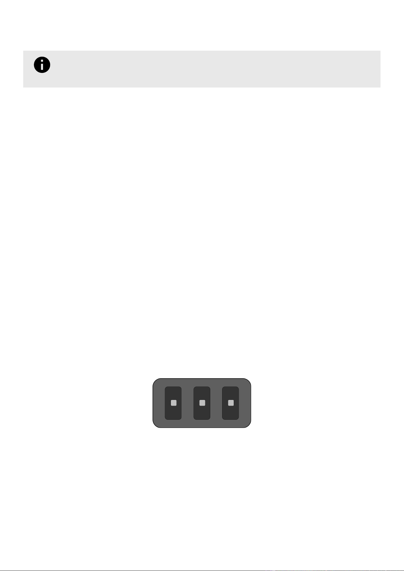
Common Troubleshooting: All Components
REMEMBER
Always disconnect the power (page 47) prior to making changes to your Component's electronics and
reconnect the power once you are done.
Front Door Does Not Stay Closed Or Latched
Vandalism or collision may cause the Front Door to not close or latch properly. If this is an electronic Component, the
LED panel may ash to indicate that a door is open.
Smart Door Open Sense Door Open
• Inspect the Front Door lock and latch, and replace if necessary.
• Ensure that no debris has built up within the LED housing, which could prevent the sensor on the Main Board from
detecting the position of the Front Door.
• Conrm that the Front Door Magnet is still in place and that it has not become cracked or corroded.
Refer to the the Support page in CLEAN to nd documents outlining replacement kits and procedures. Contact Bigbelly
Support for additional support if the problem persists.
No LEDs Lit
While Door is Closed
For a Sense or Smart, this is normal behavior for a Component that is not full. These Components only indicate when
they are full (ashing red).
For Sense Max, Smart Max, and Compost, the component will stop indicating fullness or availability (ashing red
or green) on the LED panel if Battery voltage drops below the normal operating range of 11.3 -13.5 volts. This is to
conserve energy for other functions.
• Check the battery voltage and replace the Battery as needed. Refer to the procedural documents hosted in CLEAN
or reach out to Bigbelly Support for more information.
62
LABBB6UM - Rev. 8
July 2026

While the Front Door is Open (All Electronic Components)
The Component is not getting adequate power. Check the following:
• Ensure theBattery is correctly plugged into the Main Board port indicated on the Main Board Maps (page 10).
• Check the battery voltage. LED activity will stop if the rechargeable Battery drops below seven volts or if the
non-rechargeable Battery drops below three volts.
• To replace a Battery, refer to the procedural documents hosted in CLEAN, or reach out to Bigbelly Support for more
information.
• For Components with rechargeable Batteries that are reporting adequate voltage (approximately 12 volts), check
whether the fuse has blown.
Solid Yellow LED While Front Door Is Open
A solid yellow LED that turns on when the Front Door is opened indicates a low Battery.
If this is Sense or Smart, the Battery must be replaced. If this is a Sense Max, Smart Max, or Compost, verify the
following:
For an indoor Station:
• Verify the AC Adapter is plugged into a working outlet.
• Conrm the Adapter cable, not the Solar Panel, is plugged into the "Solar" port as shown on the Main Board
Maps (page 10).
For an outdoor Station:
• Check for obstructions preventing sunlight from reaching the Solar Bubble.
• Remove any obstructions, or move the Component to a location with better sunlight.
• Examples of obstructions include trees, awnings, or scaffolding above the Component, or stickers or grafti
directly on the Solar Bubble.
NOTE
Sunlight from a window will not provide adequate energy to the Solar Panel. Stations that are
used indoors must be congured for AC power and plugged into an operating wall outlet.
• Conrm that power is reaching the Main Board from the Solar Panel.
• Use a multi-meter to test the voltage coming from the Solar Panel cable. A normal result is approximately 18
volts while unplugged from the Main Board and approximately 13 volts while plugged in.
63
LABBB6UM - Rev. 8
July 2026

•
Refer to the document in CLEAN titled "CLEAN Alert - Low Battery (Checking the Charging Circuit from the
Solar Panel) (HC5)" for the detailed procedure.
What To Do If Problems Persist
If problems persist, contact Bigbelly Support with the following information ready:
☐ Component Serial number (located to the right of the LED panel).
☐ Status of the LEDs
1. Color and status (ashing or solid) while the door is closed.
2. Color and status (ashing or solid) while the door is open.
For a solid red light with a ashing yellow LED, count the number of ashes.
☐ Location of the Component (city and street address or nearest intersection)
☐ For Components with compactors, the Ram status (upward position, partially lowered, downward position)
For more support information, refer to Support & Contact Information (page 5).
64
LABBB6UM - Rev. 8
July 2026

Compliance And Certications
The products described in this manual meet the follow certications and compliance standards:
Federal Communication Commission Class A
This device complies with part 15 of the FCC Rules. Operation is subject to the following two
conditions: (1) This device may not cause harmful interference, and (2) this device must accept
any interference received, including interference that may cause undesired operation.
This equipment has been tested and found to comply with the limits for a Class A digital device, pursuant to part 15
of the FCC Rules. These limits are designed to provide reasonable protection against harmful interference when the
equipment is operated in a commercial environment. This equipment generates, uses, and can radiate radio frequency
energy and, if not installed and used in accordance with the instruction manual, may cause harmful interference to
radio communications. Operation of this equipment in a residential area is likely to cause harmful interference in which
case the user will be required to correct the interference at his own expense.
Changes or modications not expressly approved by Big Belly Solar LLC could void the user's authority to operate the
equipment.
Waste Electrical And Electronic Equipment (WEEE) 2012/19/EU
This symbol indicates that used electrical and electronic products should not be mixed with
general household or municipal waste. For proper treatment, recovery and recycling, please
contact your dealer or supplier for further information on designated collection points where
waste maybe accepted free of charge.
Consumers play a role in re-use, recycling and other forms of recovery of WEEE and are encouraged to return WEEE as
designated in order to actively contribute to the success of such collection. Proper collection of this product ensures
specic treatment and recycling of WEEE and is necessary to achieve the chosen level of protection of human health
and the environment in the Union.
EU Declaration Of Conformity
Big Belly Solar LLC declares that the equipment described in this document complies with the requirements of the
following European Union Directives:
•
2006/42/EC Machinery Directive
•
2014/30/EU Electromagnetic Compatibility (EMC) Directive
•
2014/53/EU Radio Equipment Directive (RED)
•
2011/65/EU Restriction of Hazardous Substances (RoHS) Directive
The full EU Declaration of Conformity is available upon request from Big Belly Solar LLC.
65
LABBB6UM - Rev. 8
July 2026
Revision Block
Document
Version
Date Changes Made Since Previous Version
Rev. 1 April
2025
Initial Publication
Rev. 2 June
2025
•
Added T20 Pin-In Torx Driver Bit to list of Commonly Used Service / Mainte-
nance Tools (used for IR Sensors)
•
Added metric values for Common Tools
•
Updated Cer tications page
•
Added revised LED Guide
Rev. 3 July
2025
•
Added 9/16" Hex Bit Socket (14 mm) to list of Tools (for bolting Component to
ground)
•
In Install section "Initial Receipt of Component", added information regarding
Component Conguration Label and Colored Stickers
Rev. 4 August
2025
•
Added revised LED Guide
Rev. 5 January
2026
•
Updated list of installation tools and materials.
•
Added note about utility knife to unpacking instructions and removed all men-
tion of shrink wrap (no longer in use).
•
Updated activation instructions to reect that the Solar Panel Cable or AC Adapt-
er Cable is already plugged in upon arrival.
•
Revised Kiosking instructions.
•
Added Serial Number Range Scheme to "Product Lineup" section.
Rev. 6 May
2026
•
Removed LED Guide and all detailed Test Instructions from this Manual. Re-
placed with links to the dedicated LED Operations Guide (BB6) and Test Guide
(BB6) which reside in CLEAN.
•
Added explicit instructions for capturing install photos and a link to the BB6
Double Station Install video.
•
In "How to Connect Companion Components", corrected reversal of conditional
instructions indicating whether or not to install the ACS WIL Cable Extension
Cable.
Rev. 7 June
2026
•
Added three new cleaning products by Ecolab to "Approved Cleaning Products":
Daily Disinfectant Cleaner, Multi-Surface Disinfectant Cleaner, Facilipro 89.
•
Updated "Compliance and Certications" page.
•
Added section to "BB6 Products and Specications" showing recommended
clearance for Front Door and AC Adapter.
•
Added Liner Bag seal type to Liner Bag Specications table.
Rev. 8 July
2026
•
Updated FCC Statement on "Compliance and Certications" page.
66
LABBB6UM - Rev. 8
July 2026