1
ATTACH YOUR RECEIPT HERE
HARBOR BREEZE and logo design are trademarks or
registered trademarks of LF, LLC. All rights reserved.
DF25074
ITEM #1058359/1058592/1059423
MODEL #42311/42312/42472
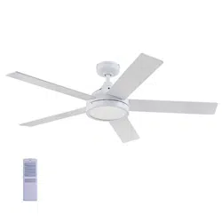
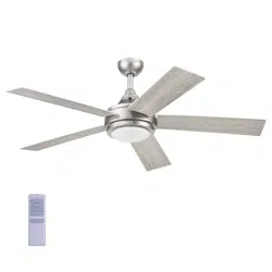
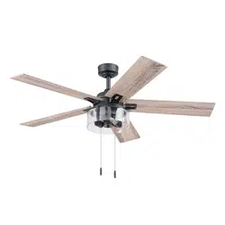
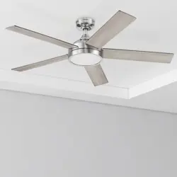
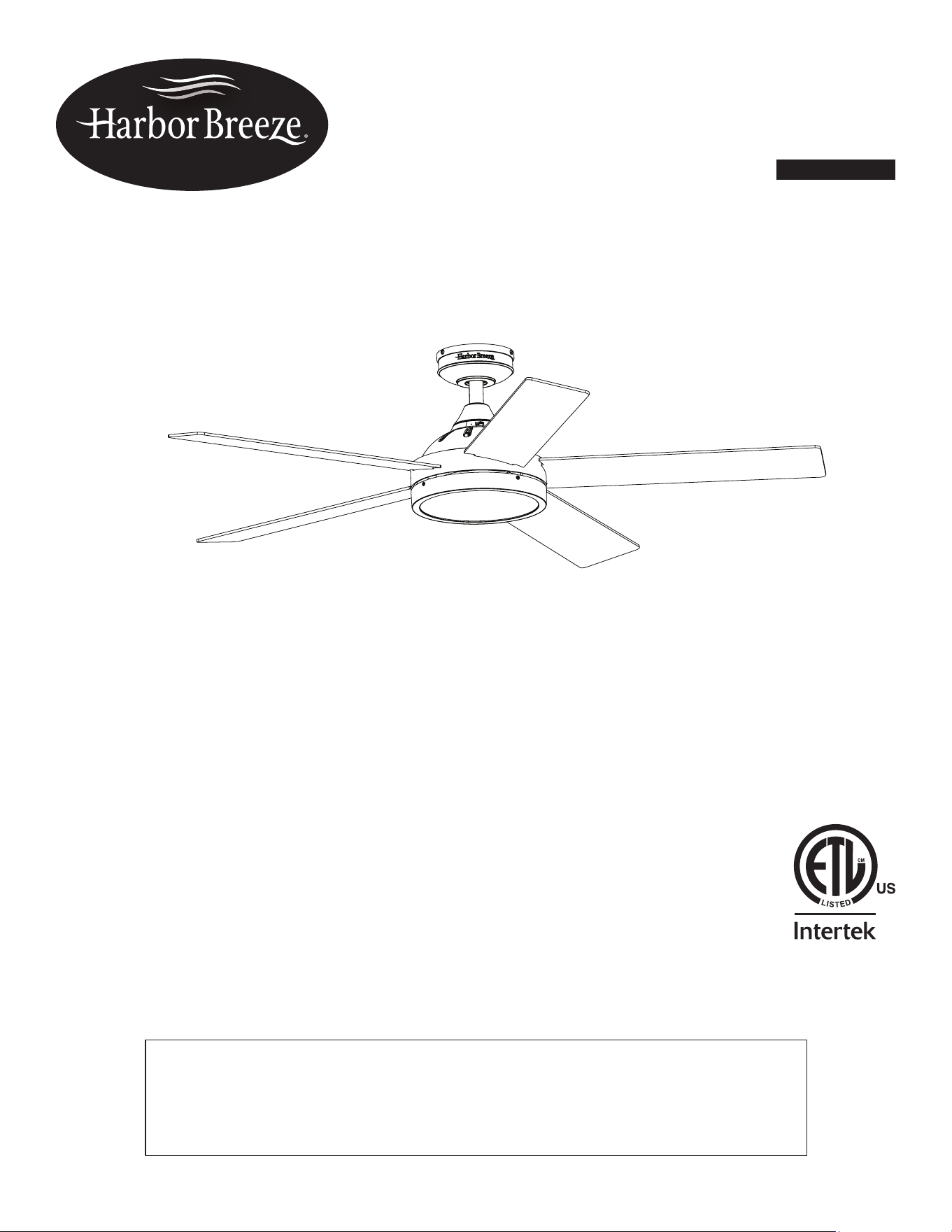
CAMDEN CEILING FAN
Español p. 20
Purchase Date _________________________
Thank you for purchasing this HARBOR BREEZE product.
Questions, problems, or missing parts?
Before returning, contact us at:
888-251-1003, 8 a.m. - 8 p.m., EST, Monday - Sunday or at [email protected].

2
TABLE OF CONTENTS
Package Contents .................................................................3
Hardware Contents ................................................................4
Safety Information .................................................................5
Preparation ......................................................................6
Initial Installation ..................................................................7
Wiring .........................................................................11
Final Installation. . . . . . . . . . . . . . . . . . . . . . . . . . . . . . . . . . . . . . . . . . . . . . . . . . . . . . . . . . . . . . . . . . 12
Operating Instructions .............................................................14
Care and Maintenance ............................................................16
Troubleshooting ..................................................................16
Limited Lifetime Warranty ..........................................................18
Replacement Parts List ............................................................19
3
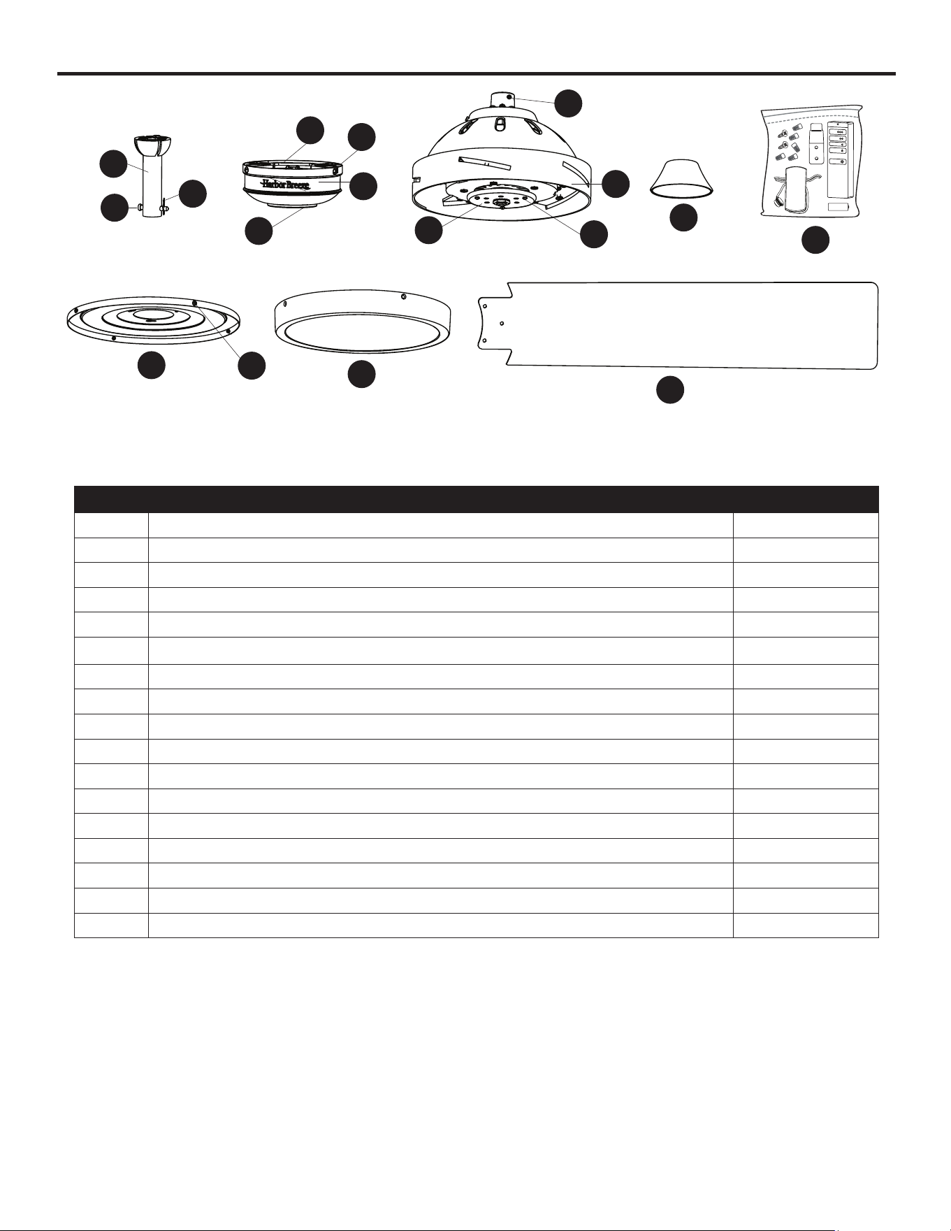
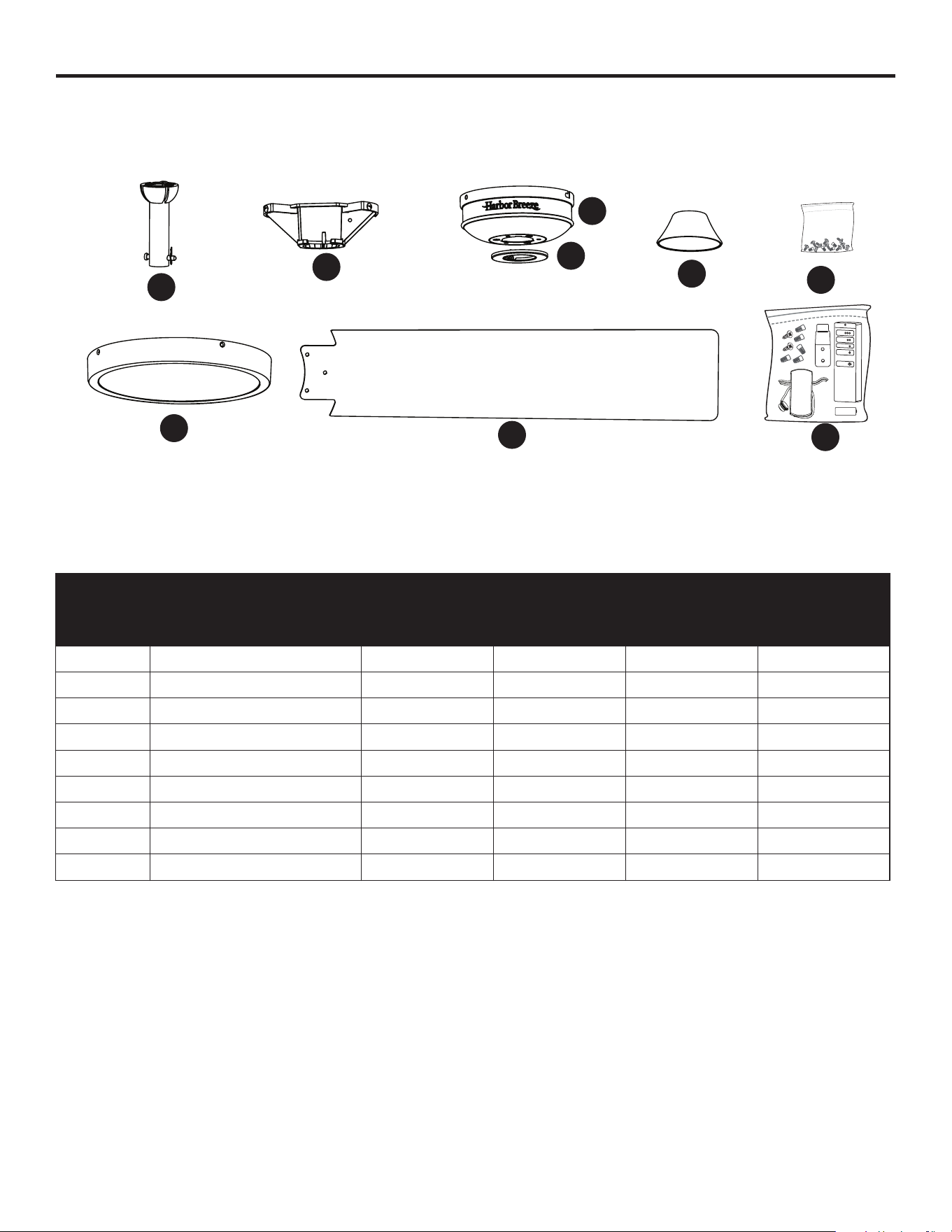
PACKAGE CONTENTS
PART DESCRIPTION QUANTITY
A Downrod 1
B Downrod Pin (preassembled to Downrod [A]) 1
C Downrod Clip (preassembled to Downrod [A]) 1
D Mounting Bracket (preassembled to Canopy [E]) 1
E Canopy 1
F Canopy Cover (preassembled to Canopy [E]) 1
G Mounting Bracket Screw (preassembled to Mounting Bracket [D]) 4
H Set Screw (preassembled to Motor Assembly [I]) 2
I Motor Assembly 1
J Fitter Plate (preassembled to Motor Assembly [I]) 1
K Fitter Plate Screw (preassembled to Fitter Plate [J]) 3
L Yoke Cover 1
M Light Pan 1
N Light Pan Screw (preassembled to Light Pan [M]) 4
O Light Kit 1
P Blade 5
Q Remote Pack 1
A
B
C
M
P
O
D
E
F
G
Q
H
I
N
K
J
L
4
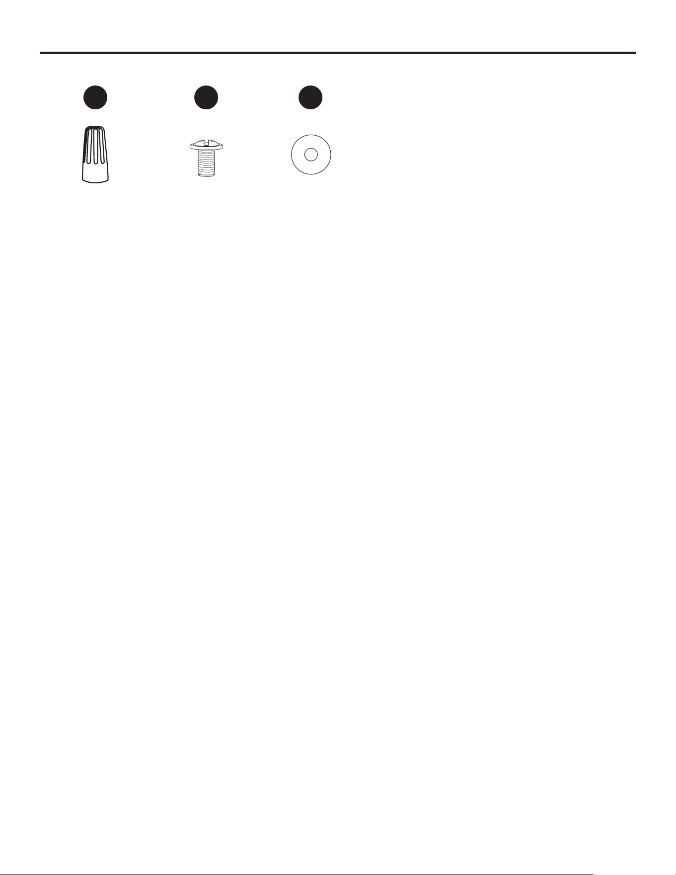
HARDWARE CONTENTS (shown actual size)
Wire Connector
Qty. 1
+ 1 extra
Blade Screw
Qty. 15
+ 1 extra
Blade Washer
Qty. 15
+ 1 extra
AA BB CC
5
SAFETY INFORMATION
Please read and understand this entire manual before attempting to assemble, operate or install the
product.
• Before you begin installing the fan, disconnect the power by removing fuses or turning o the circuit
breakers.
• Make sure all electrical connections comply with local codes, ordinances, the National Electrical
Code and ANSI/NFPA 70-199. Hire a qualied electrician or consult a do-it-yourself wiring
handbook if you are unfamiliar with installing electrical wiring.
• Make sure the installation site you choose allows a minimum clearance of 7 ft. from the blades to
the oor and at least 30 in. from the end of the blades to any obstruction.
• The net weight of this fan is: 17.22 lbs (7,81 kg).
DANGER: When using an existing outlet box, make sure the outlet box is securely attached to
the building structure and can support the full weight of the fan. Failure to do this can result in serious
injury or death. The stability of the outlet box is essential in minimizing wobble and noise in the fan
after installation is complete.
WARNING: To avoid personal injury, the use of gloves may be necessary while handling fan
parts with sharp edges.
WARNING: Using a full-range dimmer switch to control fan speed will cause a loud humming
noise from the fan. To reduce the risk of re or electric shock, do NOT use this fan with any solid-state
speed control device.
WARNING: To reduce the risk of re, electric shock or personal injury, mount the fan to an outlet
box marked “ACCEPTABLE FOR FAN SUPPORT” and use the mounting screws provided with the
outlet box. Most outlet boxes commonly used for the support of lighting xtures are not acceptable
for fan support and may need to be replaced. Consult a qualied electrician if in doubt. Secure the
outlet box directly to the building structure. The outlet box and its support must be able to support the
moving weight of the fan (at least 35 lbs.).
WARNING: To reduce the risk of re, electric shock or personal injury, wire connectors provided
with this fan are designed to accept only one12-gauge house wire and two lead wires from the fan. If
your house wire is larger than 12-gauge and/or there is more than one house wire to connect to the
two fan lead wires, consult an electrician for the proper size wire connectors to use.
WARNING: To reduce the risk of re, electric shock or personal injury, do not bend the blade
arms when installing them, balancing the blades or cleaning the fan. Do not insert objects between
the rotating fan blades.
WARNING: To reduce the risk of personal injury, use only parts provided with this fan. The use
of parts OTHER than those provided with this fan will void the warranty.
6
SAFETY INFORMATION
CAUTION: Read all instructions and safety information before installing your new fan. Review the
accompanying assembly diagrams.
CAUTION: Be sure the outlet box is properly grounded or that a ground (green or bare) wire is present.
CAUTION: Carefully check all screws, bolts and nuts on the fan motor assembly to ensure they are
secured.
CAUTION: This device complies with part 15 of FCC Rules. Operation is subject to the following
two conditions: 1) This device may cause harmful interference, and 2) this device must accept any
interference received, including interference that may cause undesired operation.
CAUTION: This equipment has been tested and found to comply with the limits for a Class B digital
device, pursuant to Part 15 of the FCC Rules. These limits are designed to provide reasonable
protection against harmful interference in a residential installation. This equipment generates,
uses and can radiate radio frequency energy and, if not installed and used in accordance with
the instructions, may cause harmful interference to radio communications. However, there is no
guarantee that interference will not occur in a particular installation. If this equipment does cause
harmful interference to radio or television reception, which can be determined by turning the
equipment o and on, the user is encouraged to try to correct the interference by one or more of the
following measures:
--Reorient or relocate the receiving antenna.
--Increase the separation between the equipment and receiver
--Connect the equipment into an outlet on a circuit dierent from that to which the receiver is
connected.
--Consult the dealer or an experienced radio/TV technician for help.
Please note changes or modications not expressly approved by the party responsible for compliance
could void the user’s authority to operate the equipment.
HKC-US
3350 Players Club Parkway, Suite 225
Memphis, TN 38125
1-888-251-1003
PREPARATION
Before beginning the assembly of this product, ensure that all parts are present. Compare all parts
with the package contents list and hardware contents list. If any part is missing or damaged, do not
attempt to assemble the product.
Estimated Assembly Time: 120 minutes
Tools Required for Assembly (not included): Electrical Tape, Phillips Screwdriver, Pliers, Safety
Glasses, Step Ladder, Wire Cutters and Wire Strippers
Helpful Tools (not included): AC Tester Light, Tape Measure and Wiring Handbook
7
INITIAL INSTALLATION
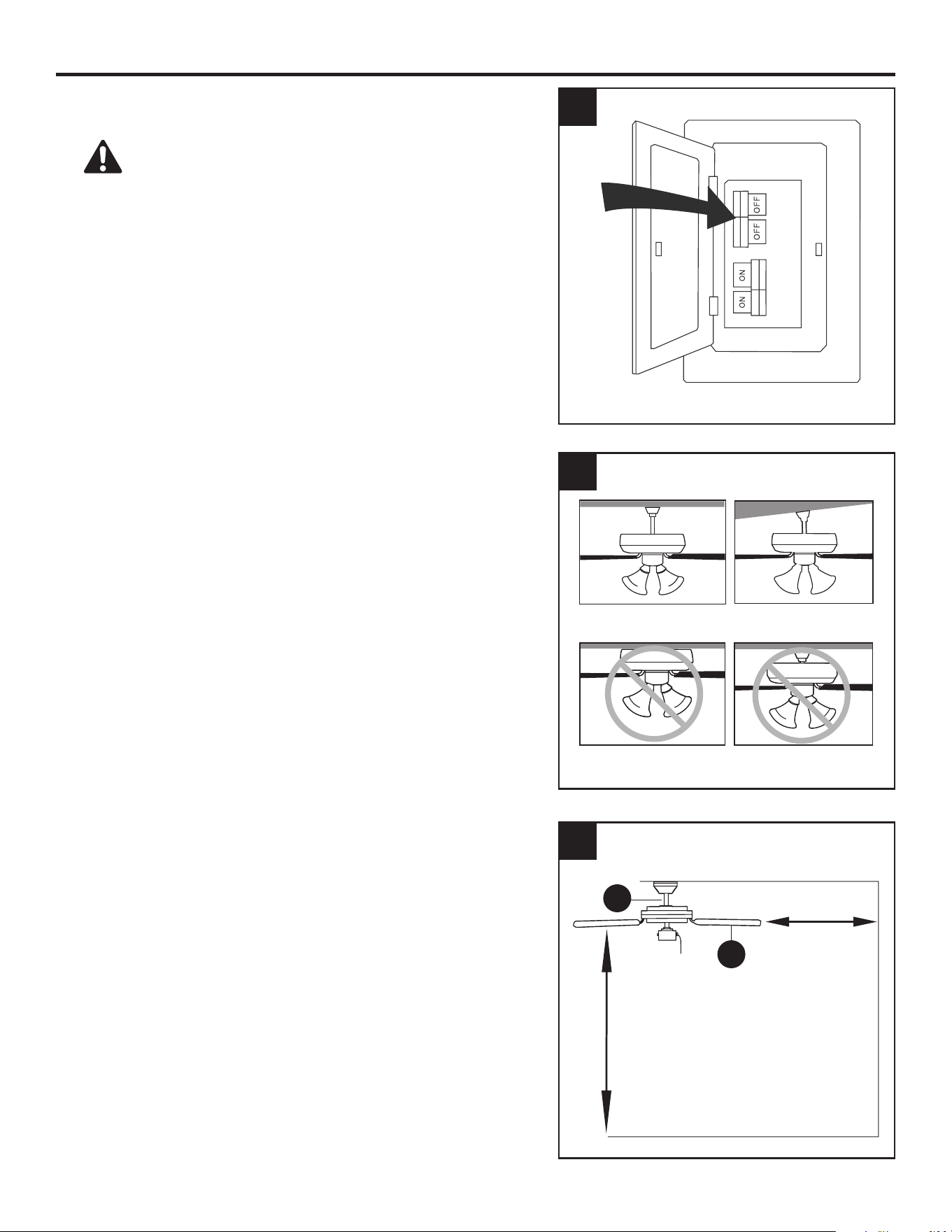
1. Turn o the circuit breakers and the wall switch to the
fan supply line leads.
DANGER: Failure to disconnect the power supply
prior to installation may result in serious injury or death.
2. Determine the mounting method to use.
Standard Mounting is best suited for ceilings 8 ft. or
higher. For taller ceilings you may want to use a longer
downrod (not included).
Angle Mounting is best suited for angled or vaulted
ceilings. A longer downrod is sometimes necessary to
ensure proper blade clearance. Note: If using the angle
mount, check to ensure the ceiling angle is not steeper
than 10°.
Flushmount installation is not available for this item.
Closemount installation is not available for this item.
Standard Mounting
Flushmount Closemount
Angle Mounting
3. Ensure the blades (P) will be at least 30 in. from any
obstructions. Also check the downrod (A) length to
ensure the blades (P) will be at least 7 ft. above the
oor.
7 feet
minimum
30 in.
minimum
3
1
P
A
2
8
D
D
INITIAL INSTALLATION
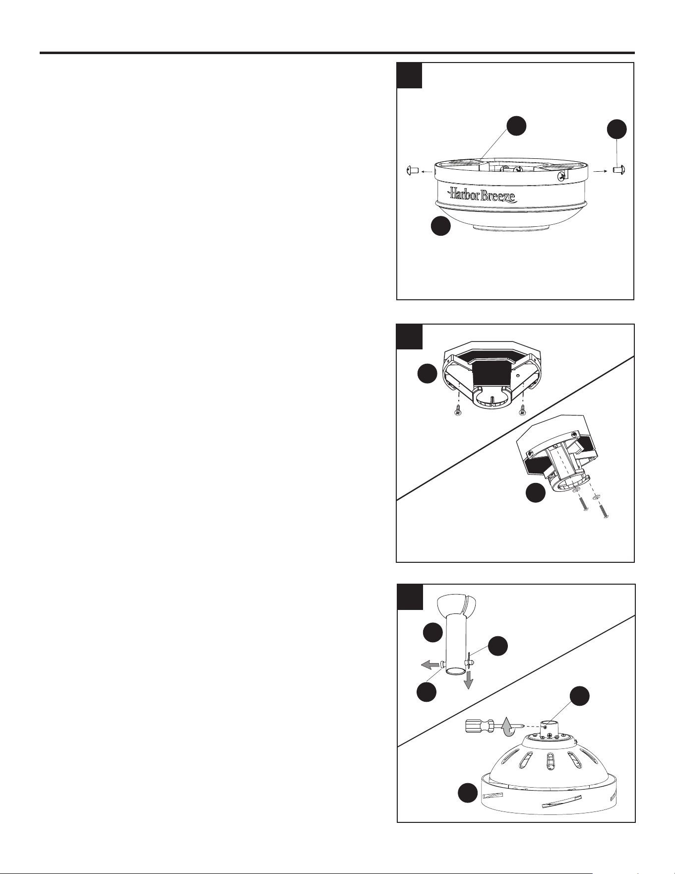
4. Loosen all four preassembled mounting bracket
screws (G), then completely remove the two
mounting bracket screws (G) from the round holes
of canopy (E). Set aside for later use. Turn the
canopy in a counterclockwise direction. Detach
mounting bracket (D) from canopy (E).
5. Attach mounting bracket (D) to outlet box (not
included) using screws and washers provided with
the outlet box.
WARNING: It is very important to use the proper
hardware when installing the mounting bracket (D) as
this will support the fan.
6. Remove the downrod clip (C) and downrod pin (B)
from the downrod (A). Then partially loosen the
set screws (H) in the yoke at the top of the motor
assembly (I).
5
6
E
D
D
D
G
C
B
I
A
H
4
Standard
Mount
Angle
Mount
9
INITIAL INSTALLATION
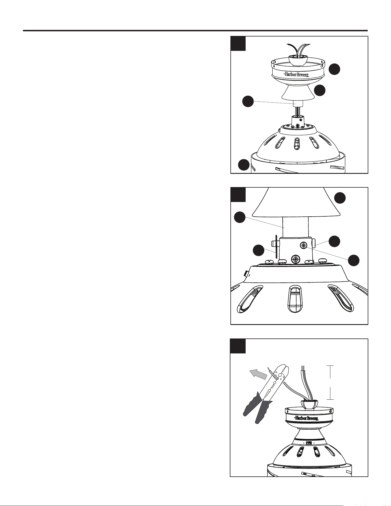
7. Insert the downrod (A) through the canopy (E)
and yoke cover (L). Feed the wires from the motor
assembly (I) through the downrod (A).
8. Slide the downrod (A) into the yoke of the motor
assembly (I), align the holes, then re-install the
downrod pin (B) and downrod clip (C). Secure with the
two set screws (H) and slide the yoke cover (L) down
until it rests on top of the motor assembly (I).
9. Depending on the length of downrod you use, you
may need to cut the lead wires back to simplify the
wiring. If you decide to cut back the lead wires, take
the lead wires and make sure you have pulled them
all the way through the top of the downrod. Measure
at least 8 inches of lead wire, then cut the excess wire
o with wire cutters (not included).
7
8
9
8 in.
E
L
L
H
C
A
B
I
A
10
INITIAL INSTALLATION
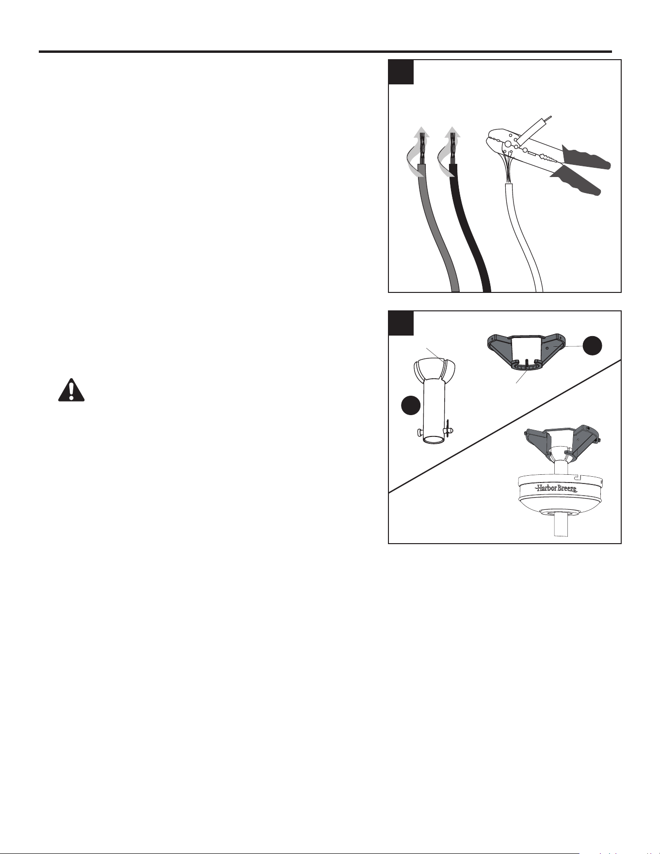
10. If you decided to cut back the lead wire in Step 9, strip
1/2 in. of insulation from the end of the white wire.
Twist the stripped ends of each strand of wire within the
insulation with pliers (not included). Repeat this step for
the black wire and blue wires.
Note: If you did not cut back the lead wires in Step 9,
Step 10 is not necessary and you may proceed to Step
11.
11. Install the ball end of the downrod (A) into the opening
of mounting bracket (D). Align one of the four slots in
the ball with the tab in the mounting bracket (D). Note:
The downrod (A) should not rotate if installed correctly.
DANGER: Failure to align the slot in the downrod
(A) with the tab of the mounting bracket (D) may cause
the fan to wobble or fall, which could result in serious
injury or death.
10
11
A
D
Slot
Tab
11
WIRING
WARNING: To reduce the risk of re, electrical shock or personal injury, wire connectors
provided with this fan are designed to accept only one 12-gauge house wire and two lead wires from
the fan. If your house wire is larger than 12-gauge and there is more than one house wire to connect
to the two fan lead wires, consult an electrician for the proper size wire connectors to use.
CAUTION: Be sure the outlet box is properly grounded or that a ground (green or bare) wire is present.
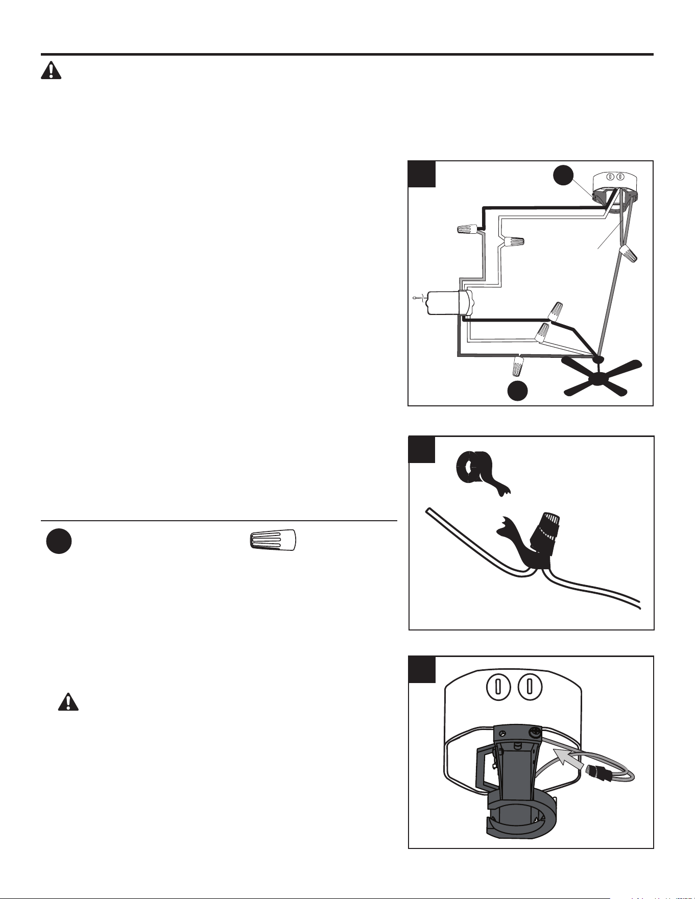
1. Secure all wiring connections together with wire connector
(AA) and the wire connectors from remote pack (Q)
according to the diagram and these steps:
• Connect the green wires from the downrod and mounting
bracket to the bare/green (ground) supply wire.
• Connect the Blue wire (FOR LIGHT) from the receiver to
the Blue fan wire.
• Connect the Black wire (TO MOTOR L) from the receiver
to the Black fan wire.
• Connect the White wire (TO MOTOR N) from the
receiver to the White fan wire.
• Connect the Red wire (AC IN L) from the receiver to the
Black (hot/power) supply wire.
• Connect the White (AC IN N) from the receiver to the
White (neutral) supply wire.
Important: After the connections have been made, the
connected wires should be turned upward and pushed
carefully up into the outlet box. Place the black and white
wire connections on opposite sides of the outlet box.
Hardware Used
AA
Wire Connector x 1
Black (hot/power)
White (neutral)
Bare/Green
(ground)
Red
White
White
White
Black
Blue
Blue
Black
Green
Green
Receiver
2. Wrap electrical tape (not included) around each
individual wire connector (AA) down to the wire.
3. Turn the spliced/taped wires upward and gently push the
wires and wire connectors (AA) into the outlet box.
WARNING: Ensure no bare wire or wire strands
are visible after making connections. Place the Green
and White wire connections on the opposite side of the
outlet box from the Black wire connections.
1
3
AA
D
2
12
FINAL INSTALLATION
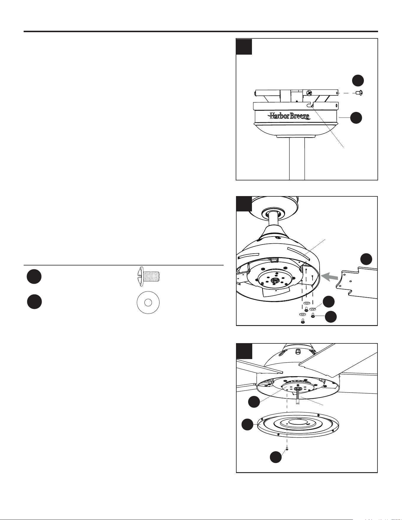
1. Align the canopy (E) over the loosened mounting
bracket screws (G) preassembled on mounting
bracket (D). Place the keyhole slot of the canopy (E)
onto the mounting bracket screws (G) and rotate the
canopy (E) clockwise. Secure the canopy (E) with
the mounting bracket screws (G) previously removed
(Step 4, page 8). Tighten all mounting bracket screws
(G) securely.
2. Insert blade (P) through slot in the side of the motor
assembly (I). Align the holes of one blade (P) with
three blade screw holes in underside of the motor
assembly (I). Secure blade (P) with three blade
screws (BB) and blade washers (CC). Repeat for the
remaining blades (P).
Hardware Used
BB
Blade Screw x 15
Blade Washer x 15
3. Remove one and loosen the other two tter plate
screws (K) but do not remove from tter plate (J).
Feed the 2-pin connector through center hole in light
pan. Align the two key slots in the light pan (M) with
the loosened tter plate screws (K). Place the light
pan (M) over the two screws and turn the light pan (M)
clockwise. Then tighten the two tter plate screws (K).
Re-install the previously removed tter plate screw (K)
and tighten rmly.
1
2
E
P
M
J
K
CC
BB
G
3
CC
2-Pin Connector
Slot
Keyhole Slot
13
FINAL INSTALLATION
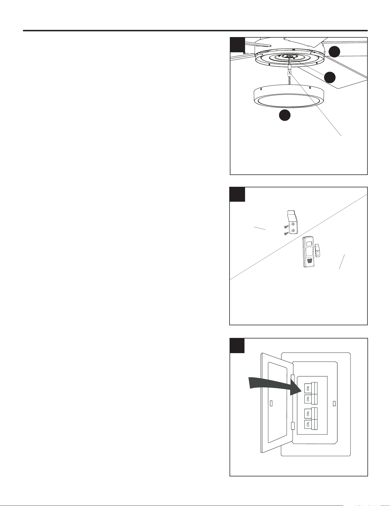
4. Remove the four light pan screws (N) preassembled
to the light pan (M).Connect the 2-pin connectors from
the fan to the 2-pin connectors from the light kit (O)
-- blue to black and white to white. Secure the light kit
with the previously removed light pan screws.
5. If desired, the mounting bracket in remote pack (Q)
can be installed to a wall using the provided mounting
screws. The remote from remote pack (Q) can be stored
in the mounting bracket for easy access.
6. Turn on power supply to the fan.
Assembly is complete.
4
O
N
M
2-Pin
Connector
5
6
Mounting Bracket
Mounting
Bracket
Mounting
Screw
14
OPERATING INSTRUCTIONS
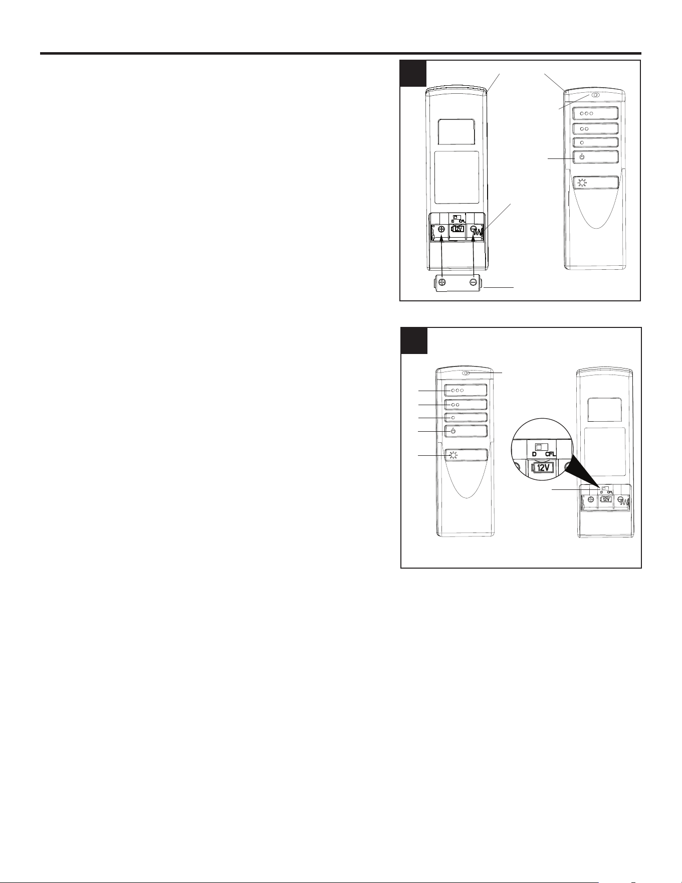
1. Remove the battery cover from the back of the remote
found in remote pack (Q). Insert the battery from remote
pack (Q) into the remote; ensuring the polarity of the
battery matches the polarity indicated in the battery
compartment -- positive (+) to positive (+) and negative
(-) to negative (-). Replace the battery cover and press
the fan power button on the remote to ensure the LED
indicator illuminates and the remote turns on the fan.
Note: If remote doesn’t turn on the fan, see
TROUBLESHOOTING (page 17).
2. To operate the fan using the remote, press and release
the following buttons:
1 - High fan speed
2 - Medium fan speed
3 - Low fan speed
4 - Fan Power - Turns the fan o.
Light Delay O mode - Press and hold the fan
power button (4) for ve seconds, which will turn
o light after one minute. The LED indicator on the
remote will ash four times to conrm mode setting.
5 - Light Control: Tap light control button to turn the light
o and on. Press and hold light control button to dim
or brighten the lights.
6 - D/CFL Switch - set to “D” at the factory. The switch
should remain in the “D” position to ensure the LED
bulb is dimmable.
1
2
3
4
5
6
2
1
Remote
Front
Back
Battery
Battery
Compartment
2
LED Indicator
LED Indicator
Fan Power
15
OPERATING INSTRUCTIONS
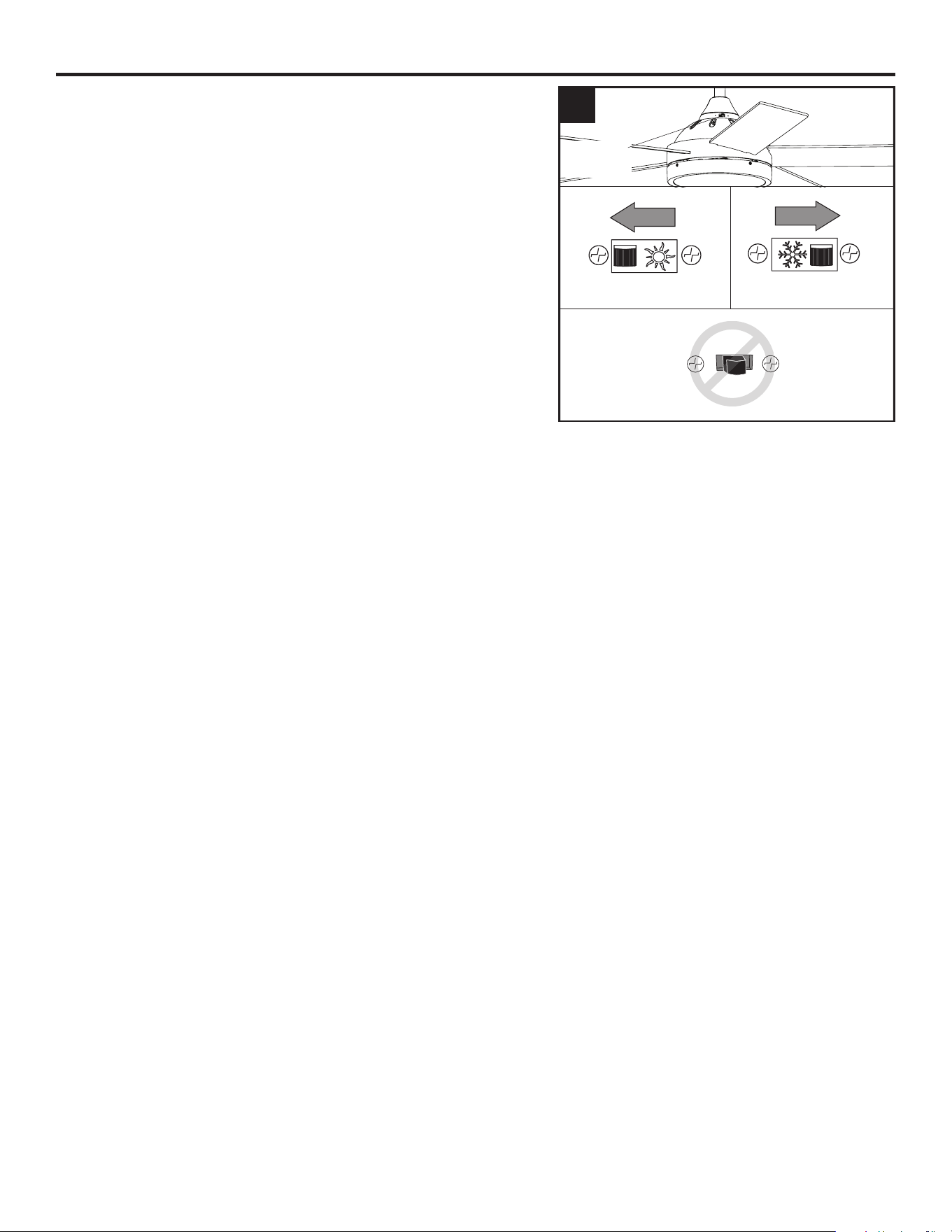
3. Using a ceiling fan will allow you to raise your
thermostat setting in summer and lower your thermostat
setting in winter without feeling a dierence in your
comfort.
In warmer weather, push the reverse switch left to
display a sun icon, which will result in downward airow
creating a wind chill eect (Fig. 3a).
In cooler weather, push the reverse switch right to
display a snowake icon, which will result in upward
airow that can help move hot air o the ceiling area
(Fig. 3b).
Important: The reverse switch must be set either
completely left or right for the fan to function correctly. If
the reverse switch is set in the middle position, the fan
will not operate (Fig. 3c).
Fig. 3a Fig. 3b
Fig. 3c
3
Reverse
Switch
16
CARE AND MAINTENANCE
At least twice each year, lower the canopy to check the downrod assembly, and then tighten all
screws on the fan. Clean the motor housing with only a soft brush or lint-free cloth to avoid scratching
the nish. Clean the blades with a lint-free cloth.
Total xture wattage is 17 watts; do not attempt to replace LED.
Battery Replacement: Use a A23, 12-volt alkaline battery. Exhausted batteries should be removed
from remote. Non-rechargeable batteries should not be recharged. Do not dispose of batteries in re,
as they may explode or leak.
Important: Shut o the main power supply before you begin any maintenance tasks. Do not use
water or a damp cloth to clean the ceiling fan.
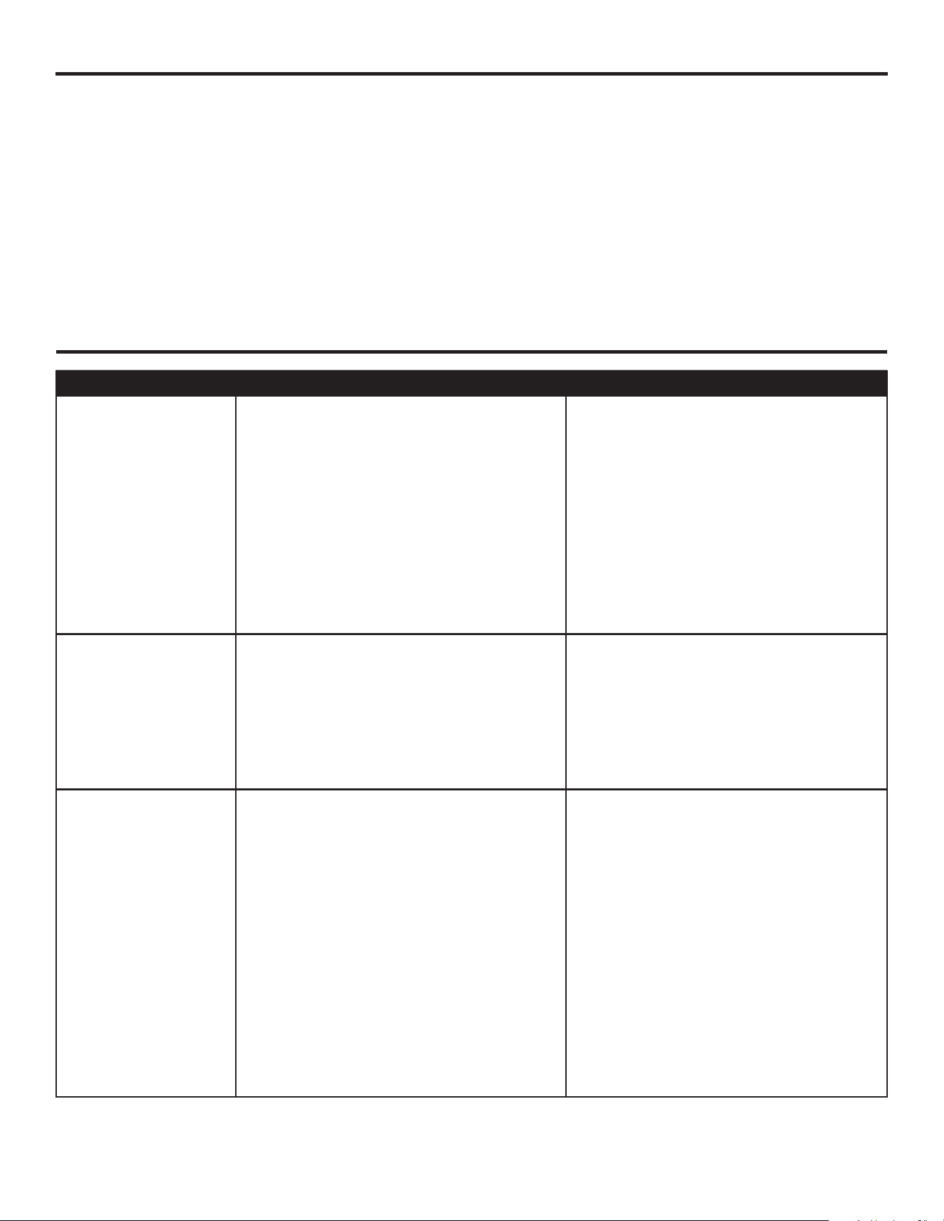
TROUBLESHOOTING
PROBLEM POSSIBLE CAUSE CORRECTIVE ACTION
The fan does not
move.
1. The reverse switch is not engaged.
2. The wall switch is turned o.
3. The power is o or the fuse
(breaker) is blown.
4. There is a faulty wire connection.
1. Firmly push the reverse switch
completely left or right.
2. Make sure the wall switch is turned
on.
3. Turn the power on or check the
fuse (breaker).
4. Turn the power o and check all
connections at the ceiling outlet
box.
The fan operates
correctly, but the
lights are not
working.
1. The light kit wire plugs are not
connected properly.
2. There is a faulty wire connection.
1. Ensure the single-pin connectors
in the light kit are connected
properly.
2. Turn the power o and check all
connections at the ceiling outlet
box.
The fan is noisy.
1. The blades are loose.
2. There is a cracked blade.
3. The wall control is not compatible
with the fan.
4. The outlet box is not secure.
5. The mounting bracket is not
secure.
1. Check and tighten all screws that
hold the fan blades to the blade
arms and the motor.
2. Replace the cracked blade.
3. Do not use a full range dimmer
switch to control the fan speed.
4. Ensure the outlet box is secured
to the building structure.
5. Ensure the mounting bracket is
secured to the outlet box and that
the screws are tight.
17
TROUBLESHOOTING
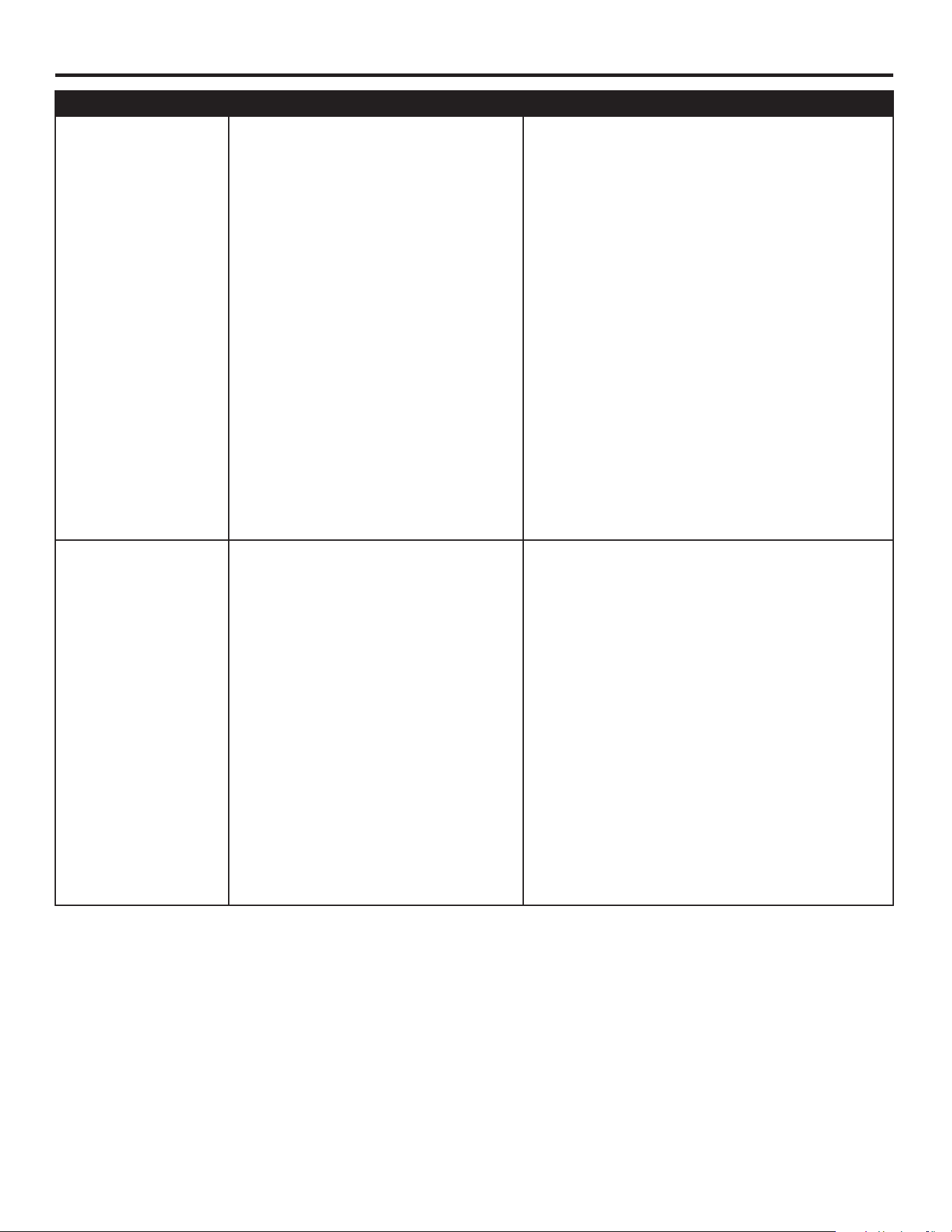
PROBLEM POSSIBLE CAUSE CORRECTIVE ACTION
There is excessive
wobbling.
1. The blades and/or blade
arms are loose.
2. The blades are unbalanced.
3. The fan mounting is not
secure.
4. The fan is too close to the
vaulted ceiling.
5. The set screw on the motor
housing yoke is loose.
1. Check and tighten all screws that hold
the fan blades to the blade arms and
the blade arms to the motor.
2. Switch one blade with a blade from
the opposite side. Or balance the
fan using a blade balancing kit (sold
separately).
3. Turn o the power. Loosen the
canopy and verify that the mounting
bracket is secure to the electrical
outlet box. The bracket must be ush
without movement against the outlet
box.
4. Use a longer downrod (sold
separately) or move the fan to
another location.
5. Lift the yoke cover and tighten the set
screw to the yoke until secure.
Remote control
does not work.
1. Power surge may have cleared
memory and remote needs to
be re-synced to the receiver.
2. Battery in remote control needs
to be replaced.
3. Interference from another
remote.
1. Turn o the main power, then turn it
back on. Within 30 seconds, press and
hold the high and low speed buttons
on the remote at the same time for
5 seconds. The LED indicator will
ash 3 times, signaling a successful
synchronization. Once complete, the fan
will start on the low speed with the light
(if applicable) o.
2. Insert new 12V battery in battery
compartment of the remote control (see
page 14).
3. If there are several fans in proximity, turn
power o to other fans and re-sync the
remote (see Corrective Action 1 above).

18
LIMITED LIFETIME WARRANTY
Set forth below, the manufacturer warrants the fan motor for this ceiling fan to be free from defects
in workmanship and material for the life of the product. Also, subject to the limitations below, the
manufacturer warrants all ceiling fan parts (“ceiling fan parts” excludes the motor and parts made in
whole or in part with glass) to be free from defects in workmanship and material for a period of one
year after the date of purchase by the original purchaser at retail.
All claims must be made by the original purchaser from an authorized dealer, whether such purchaser
purchased the product through a store or contractor. Ceiling fan part defects must be reported within
the rst year from the date of purchase. Parts made in whole or in part with glass and the nishes of
metal and other surfaces are not warranted.
Purchasers are responsible for all costs of removing and reinstalling the product. Any damage to any
part caused by ordinary wear and tear, accident, misuse, or improper installation, is not covered by
this warranty. The manufacturer assumes no responsibility whatsoever for fan installation. Any service
performed by a non-licensed electrician will render the warranty invalid.
The manufacturer’s sole responsibility shall be to repair or replace the motor, parts, or product within
the terms stated above. The manufacturer shall not be liable for any loss or damage of any kind,
including any incidental or consequential damages resulting directly or indirectly, from any breach
of warranty, express or implied, or any other failure of this product. Some states do not allow the
exclusion or limitation of incidental or consequential damages so this limitation may not apply to you.
If the original purchaser ceases to own the fan, this warranty is voided.
Should the purchaser encounter a problem with your fan related to defects in workmanship or
materials within the warranty period associated with the defective part, the manufacturer agrees to
replace the defective part without charge, or at its option, to replace the ceiling fan with a comparable
or superior model.
The manufacturer’s warranties are limited to the written warranties set out in this ceiling fan limited
lifetime warranty. All other express and implied warranties, including, without limitation, the implied
warranty of tness for a particular purpose and the implied warranty of merchantability is disclaimed.
Some states do not allow the disclaimer of implied warranties, so this disclaimer may not apply to
you.
19
Printed in China
REPLACEMENT PARTS LIST
For replacement parts, call the customer service department at 888-251-1003, 8 a.m. - 8 p.m., EST,
Monday - Sunday. You could also contact us at [email protected].
PART DESCRIPTION #1058359 #1058592 #1059423 COVERED
UNDER
WARRANTY
A Downrod 4L000006400 4L000013340 4L000009600 YES - 1 year
D Mounting Bracket 4L000007490 4L000008860 4L000014840 YES - 1 year
E Canopy 4L000007510 4L000014940 4L000014850 YES - 1 year
F Canopy Cover 4L000000830 4L000010400 4L000009630 YES - 1 year
L Yoke Cover 4A000005540 4A000009350 4L000013240 YES - 1 year
O Light Kit 4L000014860 4L000014870 4L000014880 YES - 1 year
P Blade (x5) 4A084690004 4A084690005 4A084690006 YES - 1 year
Q Remote Pack 4L000007630 4L000007630 4L000007630 YES - 1 year
HW Hardware Kit 4L000014890 4L000014900 4L000014910 NO
9734 PB • 061325
P
Q
O
L
A
D
E
F
HW