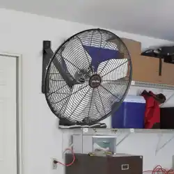
Wall Fan
User Manual
Read and save these instructions before use
Home
Model #53031
EN I 2
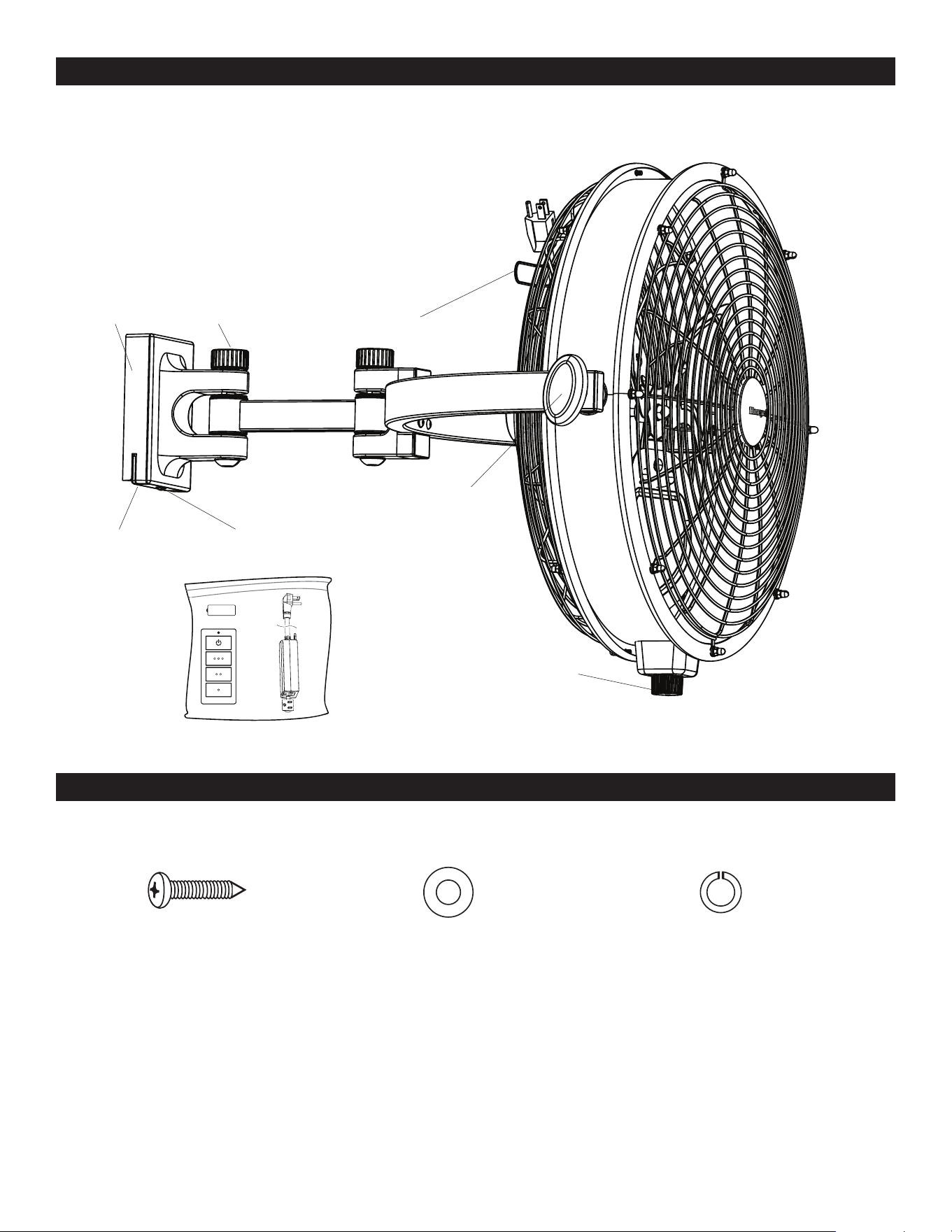
PACKAGE CONTENTS
HARDWARE CONTENTS
Tilt Knob
Cord Bracket
Pivot Knob
Fan Base
Mounting ScrewMounting Bracket
Fan Control
Note: Some extra hardware may be included. The quantity listed above is the number required for installation.
Remote Pack
Bracket Screw (x 2)
+ 2 extra
Washer (x 2)
+ 2 extra
Lock Washer (x 2)
+ 2 extra

EN I 3
SAFETY INFORMATION
THANK YOU
Please read and understand this entire manual before attempting to assemble, operate or install the product.
• Before you begin installing the fan, disconnect the power by removing fuses or turning off the circuit breakers.
• RATED FOR WET LOCATIONS. This fan is intended for indoor, damp, or outdoor use.
• The weight of the fan is 18.7 lbs.
WARNING:
• To reduce the risk of fire or electrical shock, do not use this fan with any solid state speed control device.This appliance has a
3-prong plug. To reduce the risk of electrical shock, this plug is intended to fit in an outlet only one way. If this does not fit the
outlet, contact a qualified electrician. Do not attempt to bypass this procedure.
• Failure to secure set screws on sides of the mounting bracket may result in fan falling causing serious injury or death.
CAUTION:
• Do not use fan if any part is damaged or missing.
• Connect to properly grounded outlets only.
• Do not insert fingers or any other objects through the grill guard when fan is in operation.
• Disconnect the fan when moving from one location to another.
• Disconnect the fan when removing guards for cleaning.
• Do not alter the fan’s assembly.
• CAN ICES-003 (B) / NMB-003 (B)
• CAN ICES-005 (B) / NMB-005 (B)
• This device complies with Industry Canada license-exempt RSS standard(s). Operation is subject to the following two
conditions: (1) this device may not cause interference, and (2) this device must accept any interference, including interference
that may cause undesired operation of the device (if applicable).
• This device complies with Part 15 of the FCC Rules. Operation is subject to the following two conditions: (1) this device may
not cause interference, and (2) this device must accept any interference received, including interference that may cause
undesired operation.
• This equipment has been tested and found to comply with the limits for a Class B digital device, pursuant to Part 15 of
the FCC Rules. These limits are designed to provide reasonable protection against harmful interference in a residential
installation. This equipment generates, uses and can radiate radio frequency energy and, if not installed and used in
accordance with the instructions, may cause harmful interference to radio communications. However, there is no guarantee
that interference will not occur in a particular installation. If this equipment does cause harmful interference to radio or
television reception, which can be determined by turning the equipment off and on, the user is encouraged to try to correct the
interference by one or more of the following measures:
--Reorient or relocate the receiving antenna.
--Increase the separation between the equipment and receiver
--Connect the equipment into an outlet on a circuit different from that to which the receiver is connected.
--Consult the dealer or an experienced radio/TV technician for help.
Please note changes or modifications not expressly approved by the party responsible for compliance could void the user’s
authority to operate the equipment.
HKC-US, 3350 Players Club Parkway #225, Memphis, TN 38125, 1-877-361-3883
Honeywell Ceiling Fans feature a collection of fans in various sizes and specifications to ensure your choice of indoor or outdoor
fan delivers optimum performance for your room’s size. You can trust the quality of Honeywell Ceiling Fans to deliver maximum
airflow and stylish lighting options. Honeywell Ceiling Fans use high-quality materials that are long lasting and durable to
deliver a great look and last for years to come.
EN I 4
PREPARATION
Before beginning the assembly of this product, ensure all parts are present. Compare all parts with the package contents list
and hardware contents list. If any part is missing or damaged, do not attempt to assemble the product.
Estimated assembly time: 30 minutes
Tools required (not included): Phillips screwdriver, level, drill, 1/8” drill bit, stud finder, and pencil.
CARE AND MAINTENANCE
Important: Shut off the main power supply before you begin any maintenance task. Do NOT use water or a damp cloth to clean
the fan.
At least twice each year, lower the canopy to check the downrod assembly and tighten all screws on the fan. Clean the motor
housing and blades with a soft brush or lint-free cloth to avoid scratching the finish.
Battery Replacement for Remote: Use A23 12-volt battery.
WARNING: Exhausted batteries should be removed from remote. Non-rechargeable batteries should not be recharged. Do not
dispose of batteries in fire, as they may explode or leak.
WARNING:
• This product employs overload protection (fuse). A blown fuse indicates an overload or short-circuit situation. If the fuse
blows, unplug the product from the outlet. Replace the fuse as per the user servicing instructions (follow product marking
for proper fuse rating) and check the product. If the replacement fuse blows, a short-circuit may be present and the product
should be discarded or returned to an authorized service facility for examination and/or repair.
• Do not operate any fan with a damaged cord or plug. Discard fan or return to an authorized service facility for examination
and/or repair.
• Do not run cord under carpeting. Do not cover cord with throw rugs, runners, or similar coverings. Do not route cord under
furniture or appliances. Arrange cord away from traffic area and where it will not be tripped over.
• To Reduce The Risk Of Fire, Electric Shock Or Injury To Persons, Do Not Use Replacement Parts That Have Not Been
Recommended By The Manufacturer (e.g. Parts Made At Home Using A 3D Printer).
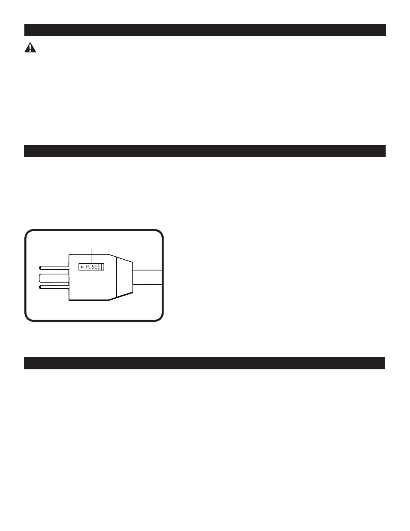
SAFETY INFORMATION
The plug is a safety feature, it contains a safety device (fuse), if your
replaceable fuse (5 Amp, 125 Volt) blows, please follow below instructions
to replace the fuse:
a) Unplug your fan, grasp plug and remove from the receptacle or other
outlet device. Do not unplug by pulling on cord.
b) Slide open the fuse cover at the side of the plug by using your thumb or a
flat screwdriver.
c) Remove the fuse carefully.
d) Put in a new 5 Amp 125 Volt fuse and make sure it is secured in place.
e) Slide back the fuse cover completely.
f) Risk of fire. Do not replace attached plug. Contains a safety device
(fuse) that should not be removed. Discard product if the attached plug is
damaged.
Plug
Fuse Door
EN I 5
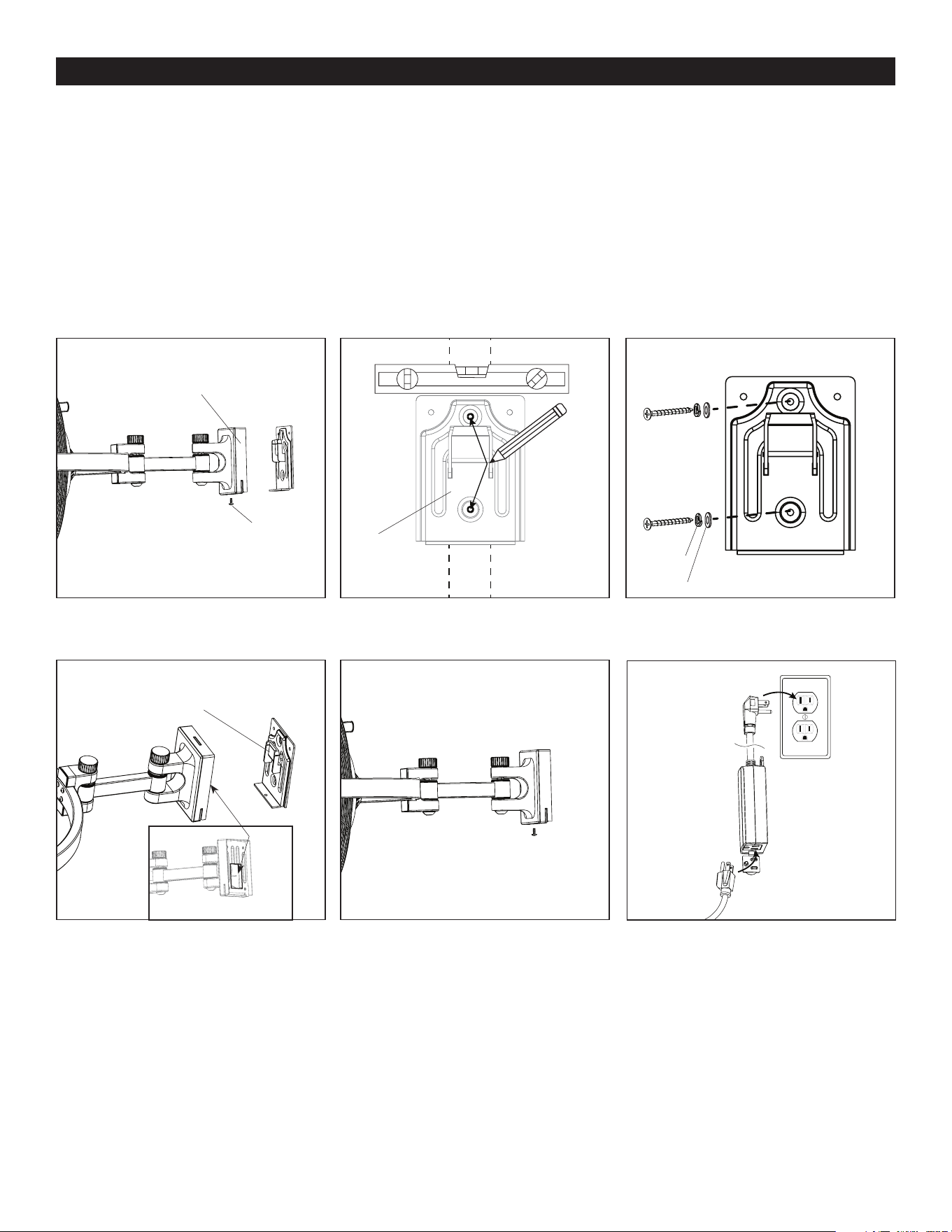
ASSEMBLY INSTRUCTIONS
1. Remove the mounting screw from the underside of the fan base. Then remove the mounting bracket (Figure 1.1).
2. Use a stud finder (sold separately) to locate the stud to which the fan will be mounted. Determine the desired height of the
mounting bracket. Hold the mounting bracket against the wall and use a level (sold separately) to ensure the mounting bracket
is level with the horizon. Then, use a pencil and mark the center of the two holes in the center of the mounting bracket. Note:
When determining the location of the fan, ensure proximity to 120 V grounded outlet. The wall fan’s power cord is 9 feet in length
(Figure 1.2).
3. Use a Phillips screwdriver to install the two bracket screws along with washers and lock washers through the mounting bracket,
drywall (if applicable), and into the stud. Note: Drilling pilot holes can make screw installation easier. If desired, use a drill with an
1/8” diameter drill bit (or smaller) to drill the pilot holes (Figure 1.3).
4. Hang the slot in the base of the fan on the hook preassembled to the mounting bracket (Figure 1.4).
5. Replace the previously removed mounting screw into the base of fan to secure the base to the mounting bracket (Figure 1.5).
6. Plug power cord into the receiver and plug the receiver into a grounded 120 V outlet (Figure 1.6).
Figure 1.1
Figure 1.4
Figure 1.2
Figure 1.5
Figure 1.3
Figure 1.6
Fan Base
Fan Base
Pencil
Level
Stud
Hook
Slot
Screw
Lock
Washer
Washer
Mounting
Screw
Mounting
Screw
Mounting
Bracket
Mounting
Bracket
Mounting
Bracket
Mounting Bracket
Receiver
Plug from fan
120 V
grounded
outlet
EN I 6
ASSEMBLY INSTRUCTIONS
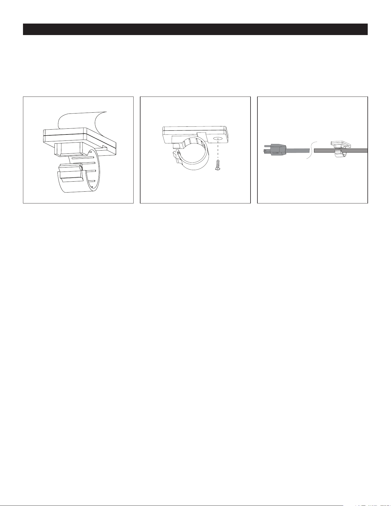
7. Use cord clips to secure the fan’s power cord in a path toward the power outlet. Peel the backing off of the double-sided tape
preassembled to back side of each cord clip (Figure 1.7).
8. (Optional) Cord clips have a round hole to accommodate a wood screw (sold separately) as an option to the taping method
(Figure 1.8).
9. Secure each cord clip to the wall. Then insert the cord into each clip and press the clip closed to secure the cord. Note: Leave
adequate slack near the fan to allow fan to swivel and/or tilt (Figure 1.9).
Figure 1.8Figure 1.7 Figure 1.9
Wood Screw
(not included)
EN I 7
OPERATING INSTRUCTIONSOPERATING INSTRUCTIONS
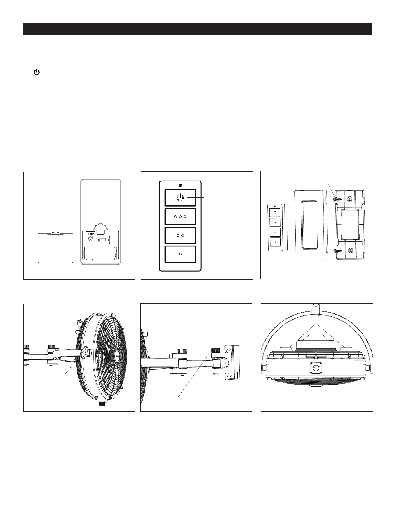
1. Remove the battery door from the back of the remote using a flat-head screwdriver (not included). Insert the battery; ensure
polarity of battery matches the polarity indicated in the battery compartment -- positive (+) to positive (+) and negative (-) to
negative (-). Replace the battery cover (Figure 2.1),
2. To operate the fan using the remote, press and release the following buttons (Figure 2.2:
- Turns the power to fan off.
o o o - Turns on fan at high speed.
o o - Turns on fan at medium speed.
o - Turns on fan at low speed.
Note: When using the remote, ensure the fan control is manually set to high (3) speed.
3. If desired, the wall bracket in remote pack can be installed to a wall using the provided mounting screws. Once the wall
bracket is installed, snap the front cover onto it. The remote can be stored in the wall bracket for easy access (Figure2.3).
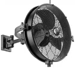
4. Use tilt knobs on sides of fan to adjust airflow up or down. Loosen tilt knobs by turning counterclockwise, adjust fan, and
retighten tilt knobs (Figure 2.4).
5. There are two pivot hinges between the base and the fan. To adjust the hinges, loosen the pivot knobs, move fan in desired
direction and tighten the pivot knobs (Figure 2.5).
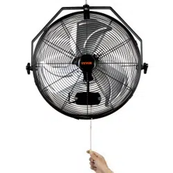
6. Cord Brackets are located on back of fan. When not in use, wrap power cord around the two cord brackets (Figure 2.6).
Figure 2.3
Figure 2.4
Figure 2.5
Figure 2.2Figure 2.1
Figure 2.6
Tilt Knob
Pivot Knob
Cord Brackets
Off
High Speed
Medium Speed
Low Speed
Wall BracketFront Cover
Mounting Screw
Remote
Battery
EN I 8
The fan does not
move.
The fan does not
move.
1. Ensure the main power cord/receiver is plugged into a 120V receptable and fan control is set to High
Speed (3) .
2. Turn the power on or check the fuse (breaker).
Install new 12V (23A) battery in the battery compartment of the remote.
PROBLEM CORRECTIVE ACTION
TROUBLESHOOTING
WARRANTY
If you experience any faults, please check the Troubleshooting section below. If a problem cannot be remedied or you are
experiencing difficulty in installation, please contact Customer Service: 1-877-361-3883, Monday - Friday, 8am - 5pm, Central.
WARNING: Shut off the power supply before you begin any maintenance task.
The manufacturer warrants all of its utility fans against defects in materials and workmanship for three (3) years from the date of
purchase. If within this period the product is found to be defective, take a copy of the bill of sale as a proof of purchase and the
product in its original carton to the place of purchase. The manufacturer will, at its option, repair, replace or refund the purchase
price to the consumer. All costs of installation and removal of the fixture is the responsibility of the consumer. This warranty
does not cover utility fans becoming defective due to misuse, accidental damage or improper handling and/or installation and
specifically excludes liability for direct, incidental or consequential damages. As some states do not allow exclusions of limitations
on an implied warranty, the above exclusion and limitation may not apply. This warranty gives you specific rights and you may also
have other rights which may vary from state to state.
The Honeywell Trademark is used under license
from Honeywell International Inc.
Honeywell International Inc. makes no
representations or warranties with respect to
this product.
This product is manufactured for
Hong Kong China Electric Appliance, LTD.
3350 Players Club Parkway, Suite 225
Memphis, TN 38125
1 (877) 361-3883
10202 • 021225
Home