About This ManualAbout This Manual

Thank you for choosing the Akuvox A08 access control terminal. This manual is intended for the administrators who
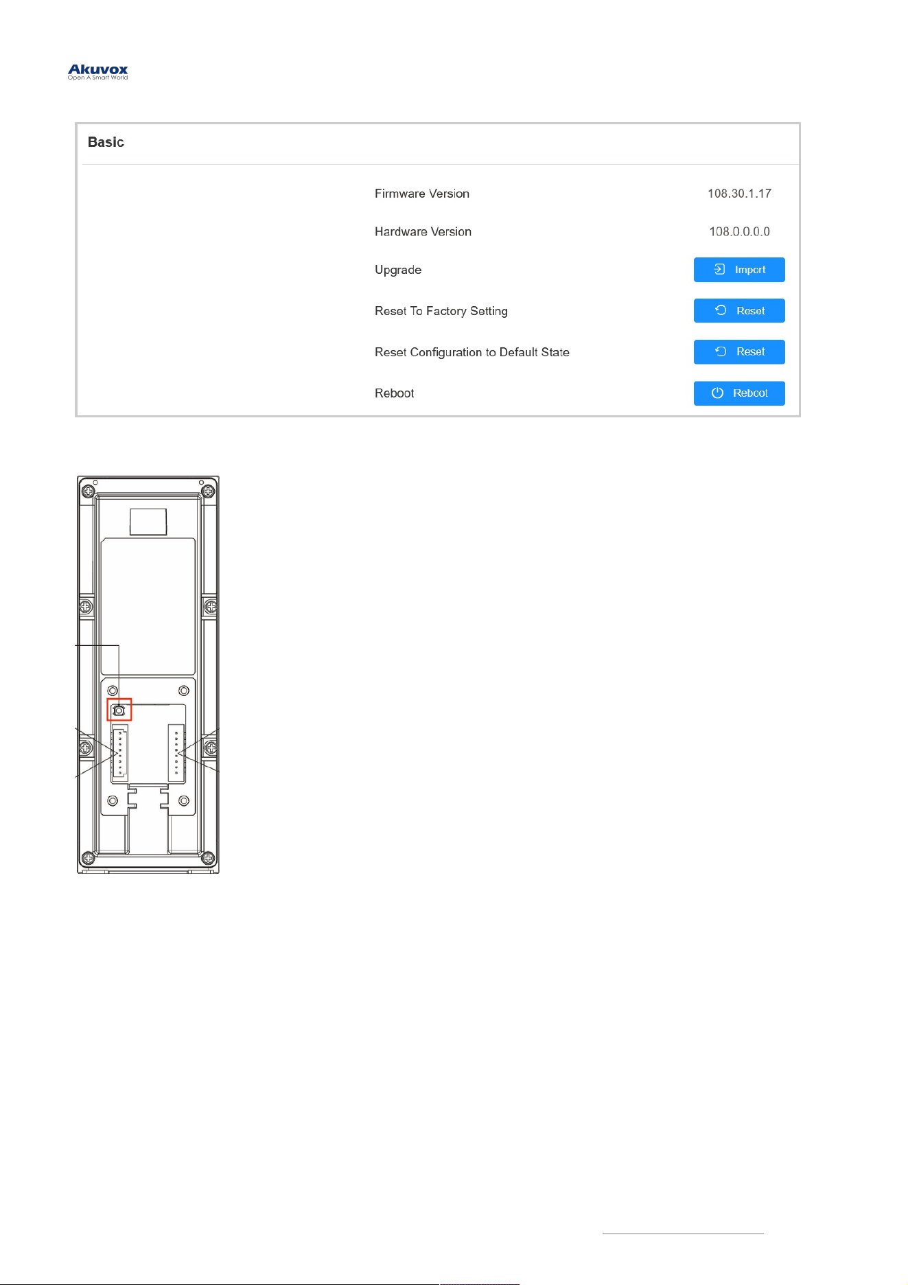
need to properly configure the access control terminal. This manual is written based on firmware version 108.30.1.17,
and it provides all the configurations for the functions and features of the A08 access control terminal. Please visit the
Akuvox forum or consult technical support for any new information or the latest firmware.
And the hardware version of A08
is 0.0.0.0.
Akuvox A08 series integrates a door controller and card reader into a single device, significantly reducing costs for
building operators. It provides versatile credentials such as PIN codes, QR scanning, wave-to-unlock via Bluetooth,
and mobile access via NFC and RFID cards.
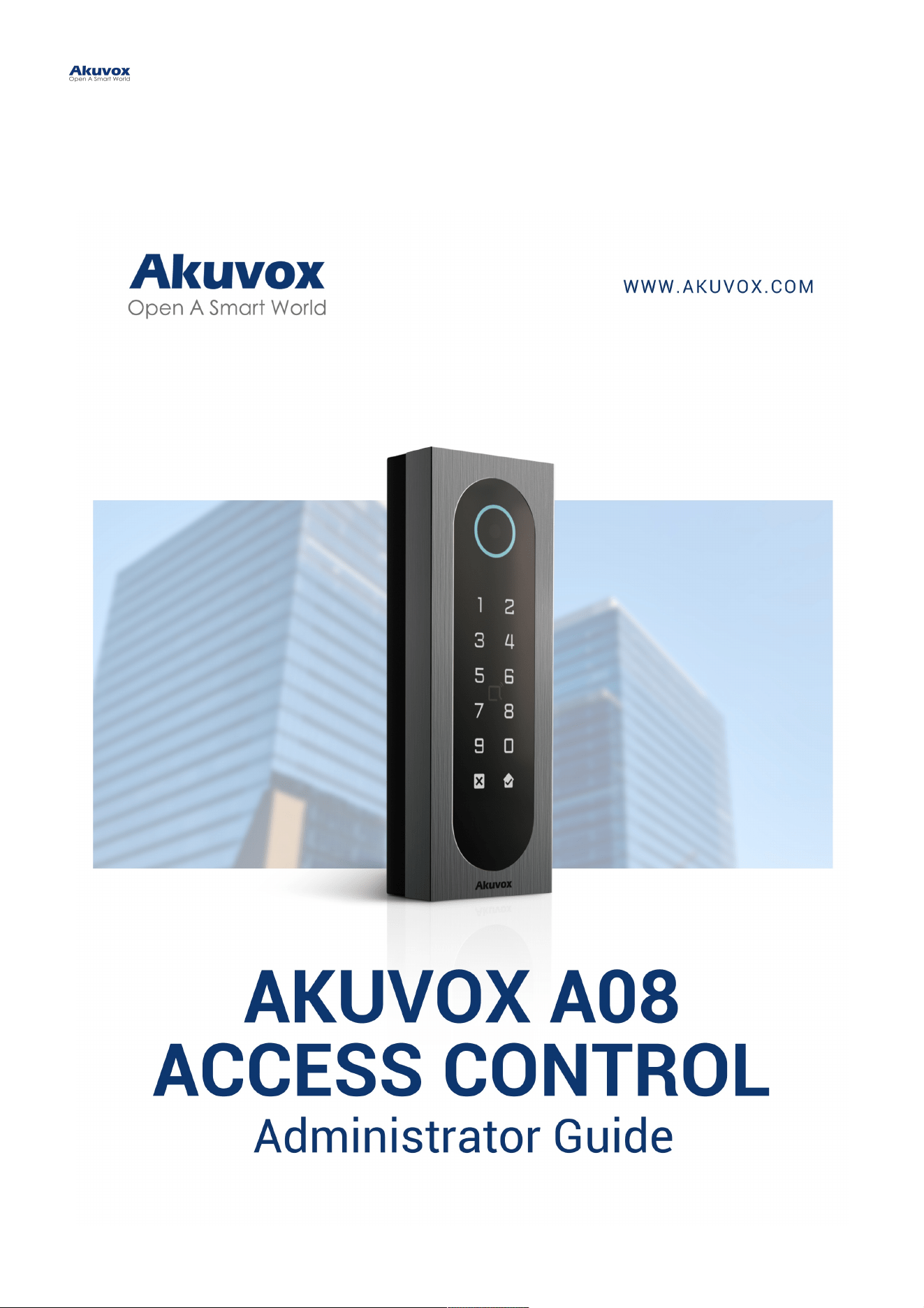
Product OverviewProduct Overview

ModelModel A08SA08S A08KA08K
Front Panel Toughened Glass Toughened Glass
Frame Aluminum Alloy Aluminum Alloy
RFID Card Reader 13.56MHz & 125kHz 13.56MHz & 125kHz
Relay Out x1 x1
Inputs x2 x2
Wiegand ✔ ✔
RS485 ✔ ✔
Speaker 8Ω / 0.5W 8Ω / 0.5W
Tamper Proof Alarm ✔ ✔
Ethernet Port RJ45, 10/100Mbps adaptive RJ45, 10/100Mbps adaptive
Power Output 12V 600mA 12V 600mA
Power Supply 12V DC connector (if not using PoE) 12V DC connector (if not using PoE)
QR Code UnlockQR Code Unlock ✔ X
Bluetooth UnlockBluetooth Unlock ✔ X
Model Specifications and DifferencesModel Specifications and Differences
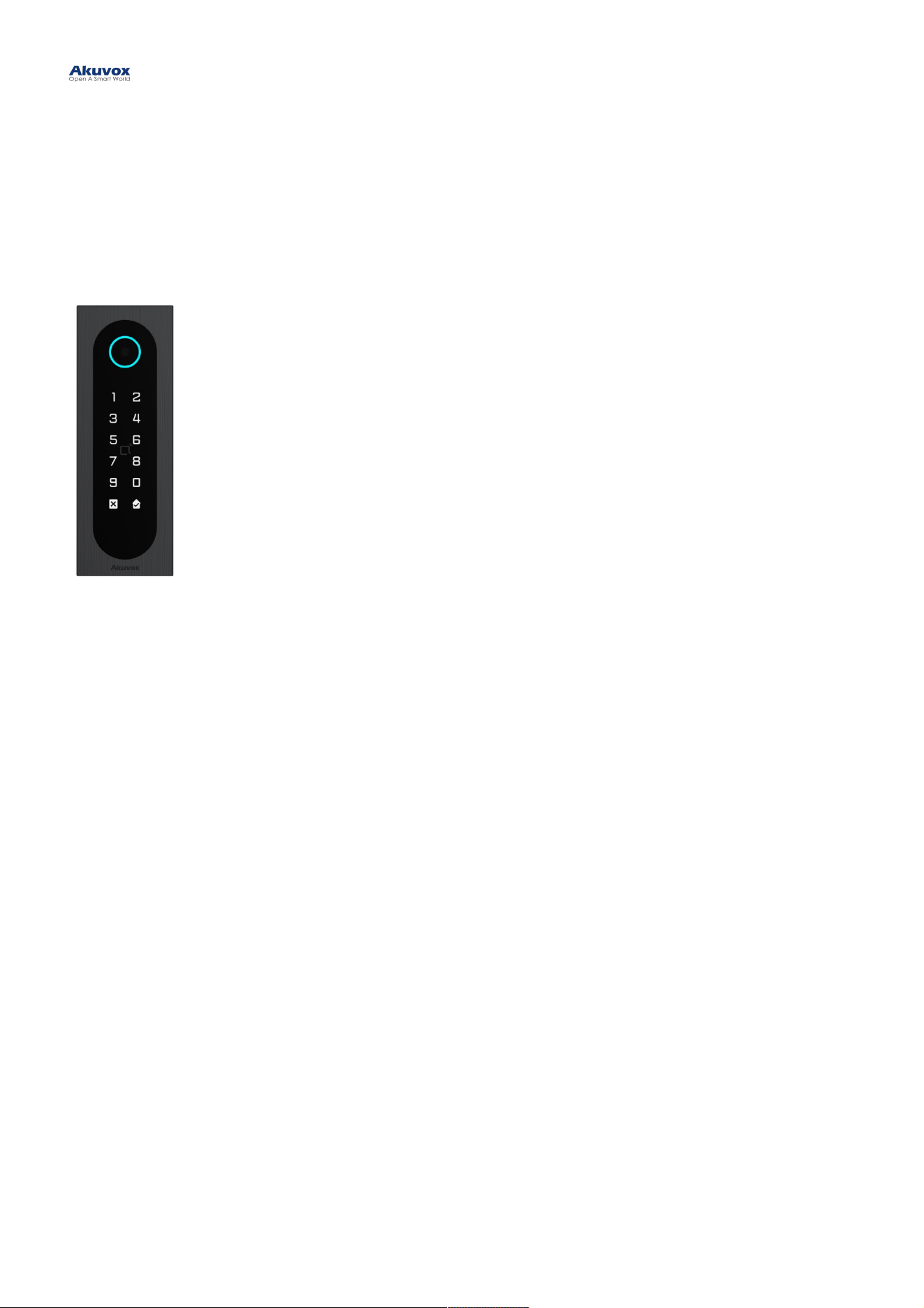
StatusStatus: This section gives you basic information such as product information, network information, and
access logs.
NetworkNetwork: This section covers LAN port settings.
Access ControlAccess Control: This section covers relay, input, web relay, card setting, Bluetooth setting, etc.
DirectoryDirectory: This section includes access schedule management and user management.
DeviceDevice: This section includes light, Wiegand, lift control, and audio settings.
SettingSetting: This section deals with time and language settings, relay schedule, action, HTTP API settings, etc.
SystemSystem: This section covers firmware upgrade, device reset, reboot, configuration file auto-provisioning,
system log and PCAP, password modification as well as device backup.
Introduction to Configuration MenuIntroduction to Configuration Menu
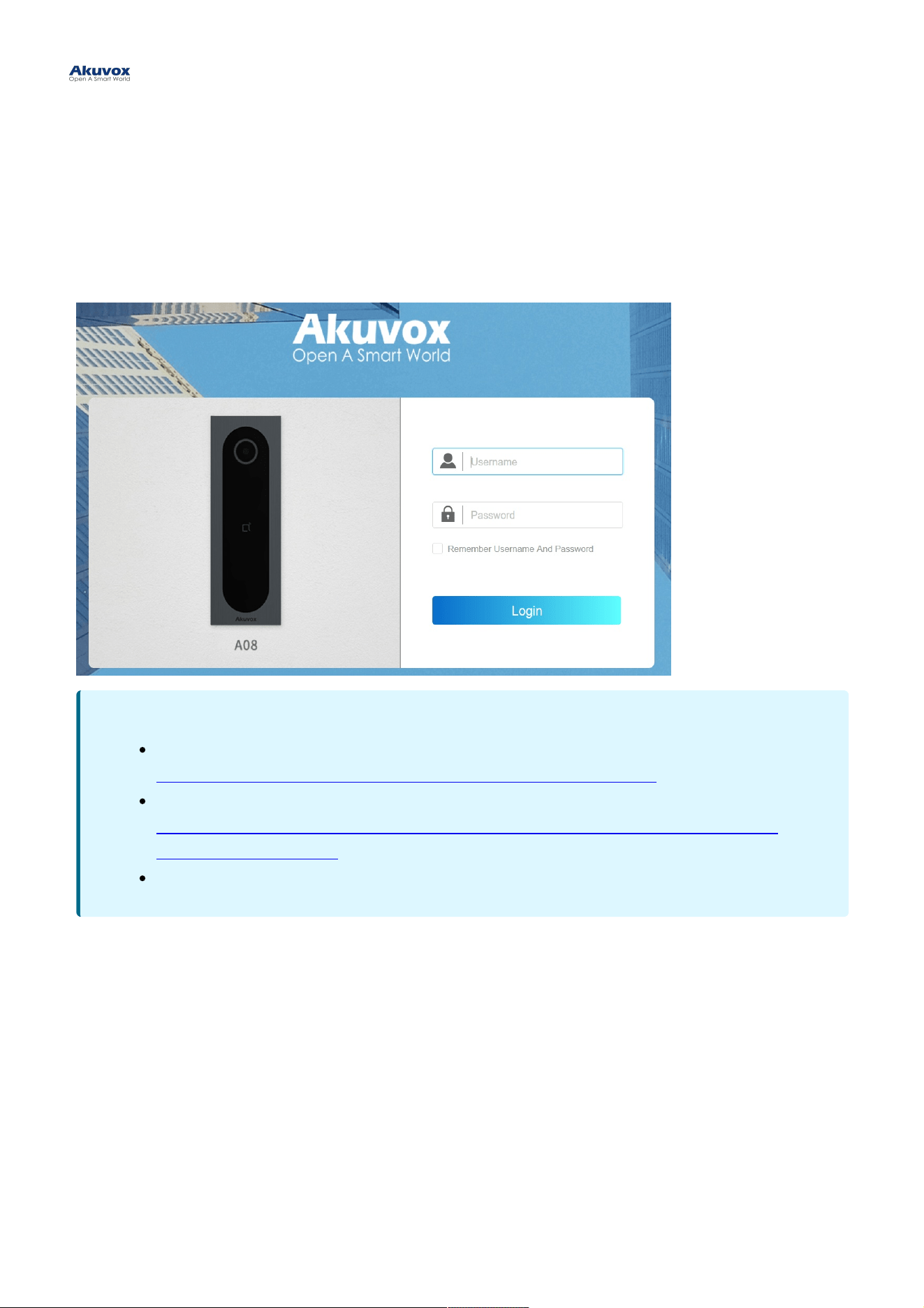
Before configuring A08, please make sure the device is installed correctly and connected to a normal network. Using
the Akuvox IP scanner tool to search the device IP address in the same LAN. Then use the IP address to log into the
web browser. The default username and password are adminadmin.
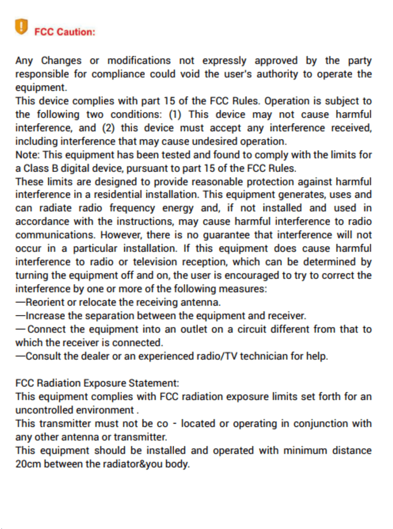
You can also obtain the IP address by pressing the ResetReset button at the back of the device. The device will announce
the IP address automatically.
Access the DeviceAccess the Device
NoteNote
Download IP scanner:
https://knowledge.akuvox.com/docs/akuvox-ip-scanner?highlight=IPhttps://knowledge.akuvox.com/docs/akuvox-ip-scanner?highlight=IP
See detailed guide:
https://knowledge.akuvox.com/v1/docs/en/how-to-obtain-ip-address-via-ip-scanner?https://knowledge.akuvox.com/v1/docs/en/how-to-obtain-ip-address-via-ip-scanner?
highlight=IP%20Scannerhighlight=IP%20Scanner
Google Chrome browser is strongly recommended.
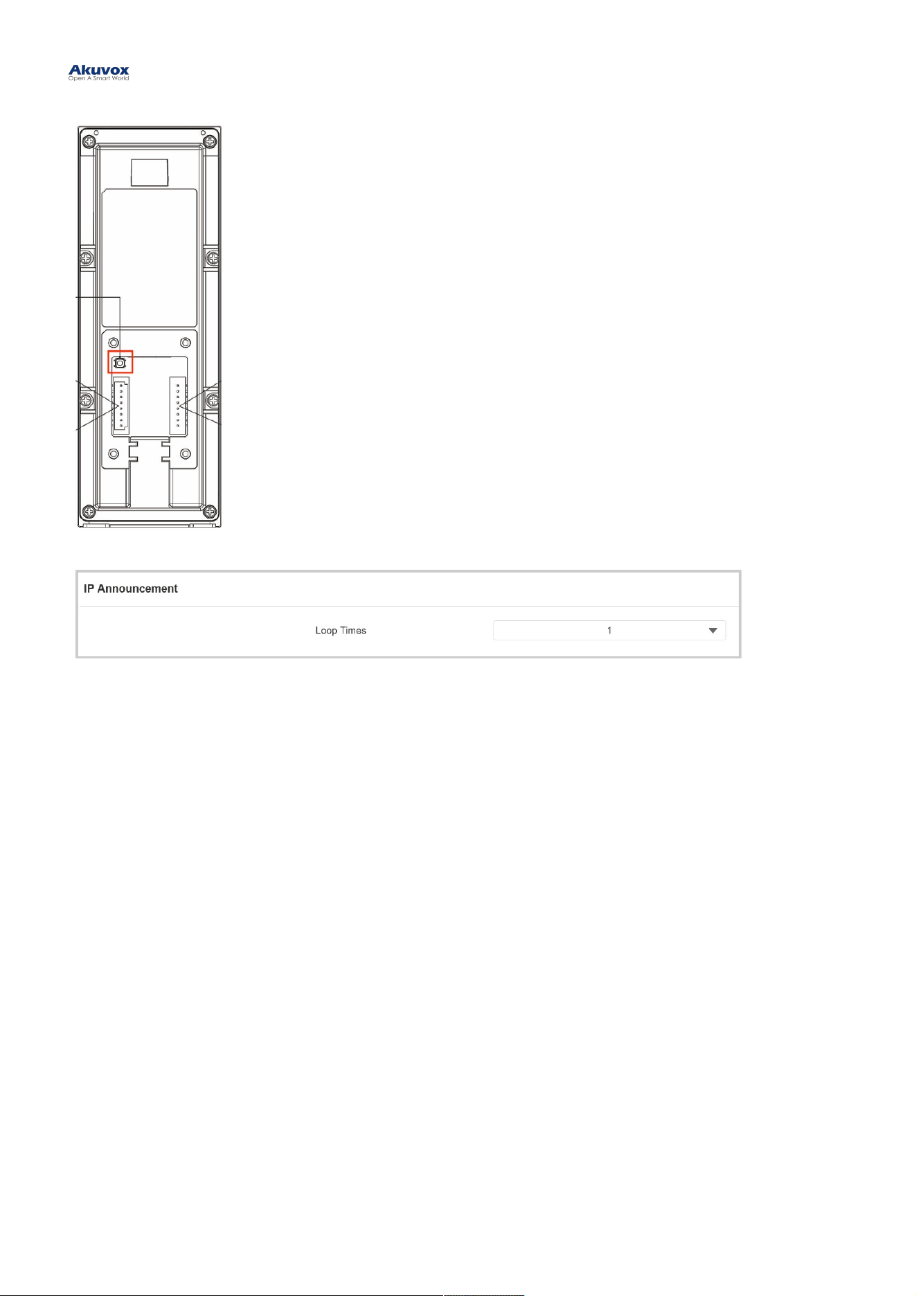
You can set up the loop times of the IP announcement on the Device > Audio > IP AnnouncementDevice > Audio > IP Announcement interface.
LanguageLanguage
You can switch the web language between English and Chinese in the upper right corner.
You can customize interface text including configuration names and prompt text.
To set it up, go to Setting > Time/LangSetting > Time/Lang interface. Export and edit the .json file. Then import the file to the device.
TimeTime
Time settings on the web interface allows you to set up the NTP server address that you obtained to automatically
synchronize your time and date. When a time zone is selected, the device will automatically notify the NTP server of the
time zone so that the NTP server can synchronize the time zone setting in your device.
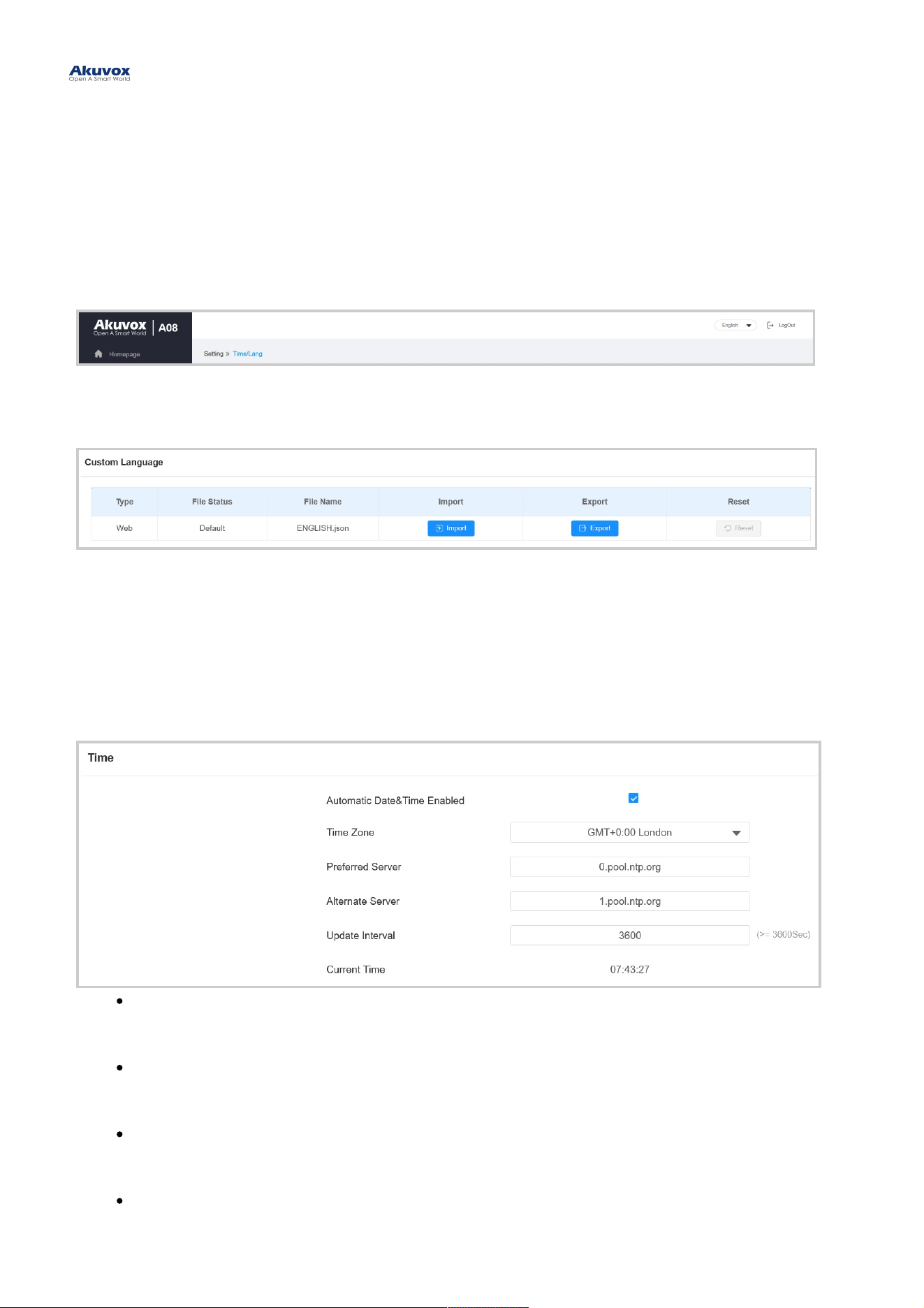
To set up time, go to Setting > Time/LangSetting > Time/Lang interface.
Automatic Date&Time EnabledAutomatic Date&Time Enabled: Set whether the device updates the time automatically via the Network
Time Protocol(NTP) server.
Date/TimeDate/Time : Set the date and time for the device manually when you disable the automatic date and time
service.
Time ZoneTime Zone: Select the specific time zone based on where the device is used. The default time zone is
GMT+0:00.
Preferred ServerPreferred Server: Enter the primary NTP server address for updating the time. The default NPT server
address is 0.pool.ntp.org.
Language and Time SettingLanguage and Time Setting

Alternate ServerAlternate Server: Enter the backup NPT server address when the primary one fails.
Update IntervalUpdate Interval: Set the time update interval. For example, if you set it as 3600s, the device will send a
request to the NPT server for the time update every 3600 seconds.
Current TimeCurrent Time : Display the current device time.
Status LightStatus Light
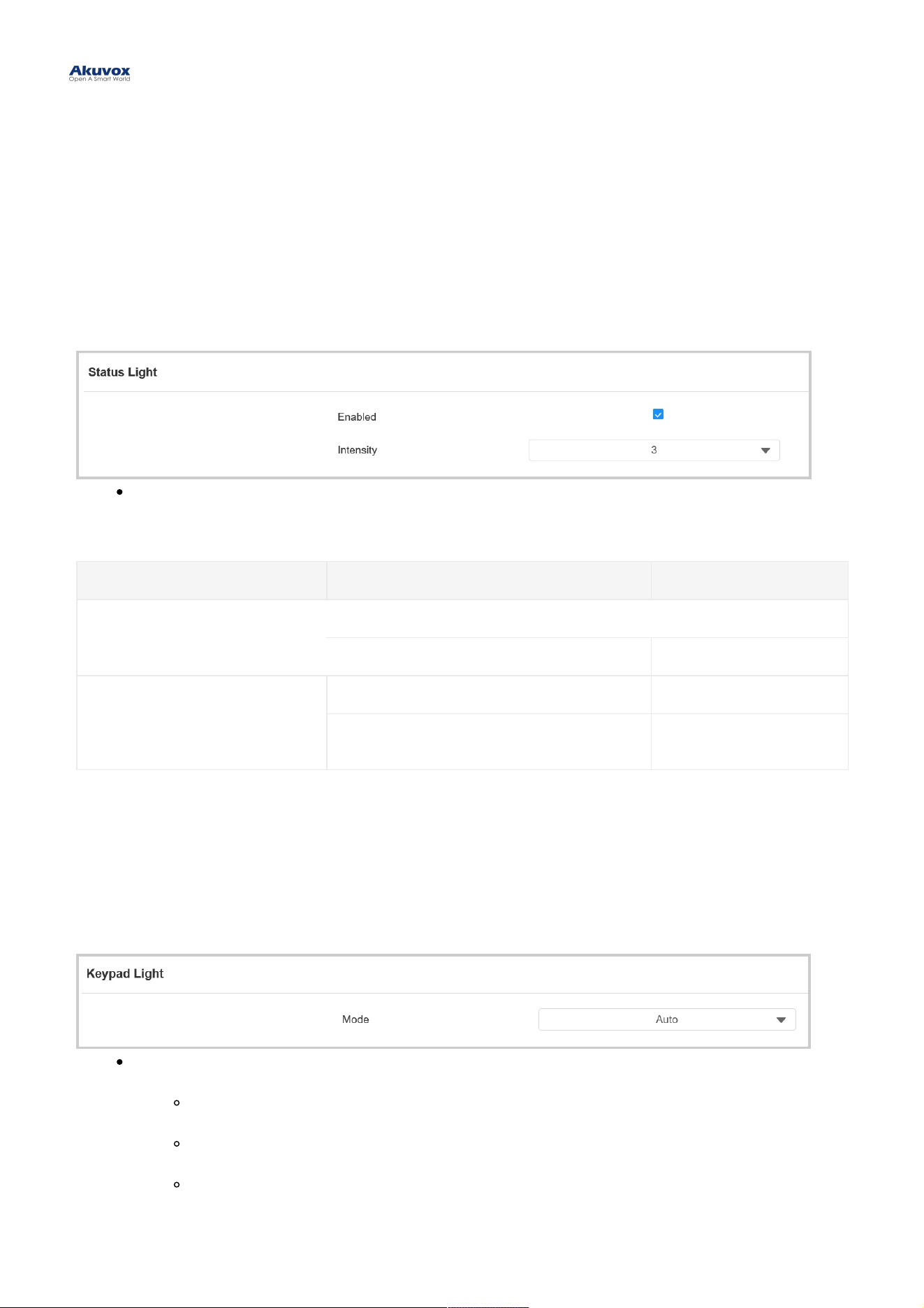
You can turn on or off the status light and adjust its brightness.
To set it up, go to Device > Light > Status LightDevice > Light > Status Light interface.
Status LightStatus Light: The level ranges from 1-5. The higher the value is, the brighter it is.
Status Light DescriptionStatus Light Description:
LED ColorLED Color LED StatusLED Status DescriptionDescription
Light Blue
Light on briefly The device starts up.
The light circle rotates once. Door-opening succeeds.
Blue
Flashing briefly Door-opening fails.
Flashing continuously
The tamper alarm is
triggered.
Keypad LightKeypad Light
You can set up the keypad light. For example, keep the light on, and users can locate the device conveniently in a dark
environment.
To set it up, go to Device > Light > Keypad Light Device > Light > Keypad Light interface.
ModeMode :
AutoAuto: The keypad lights up when users approach or touch it.
OnOn: Turn on the keypad light all the time.
OffOff: Turn off the keypad light all the time.
LED SettingLED Setting
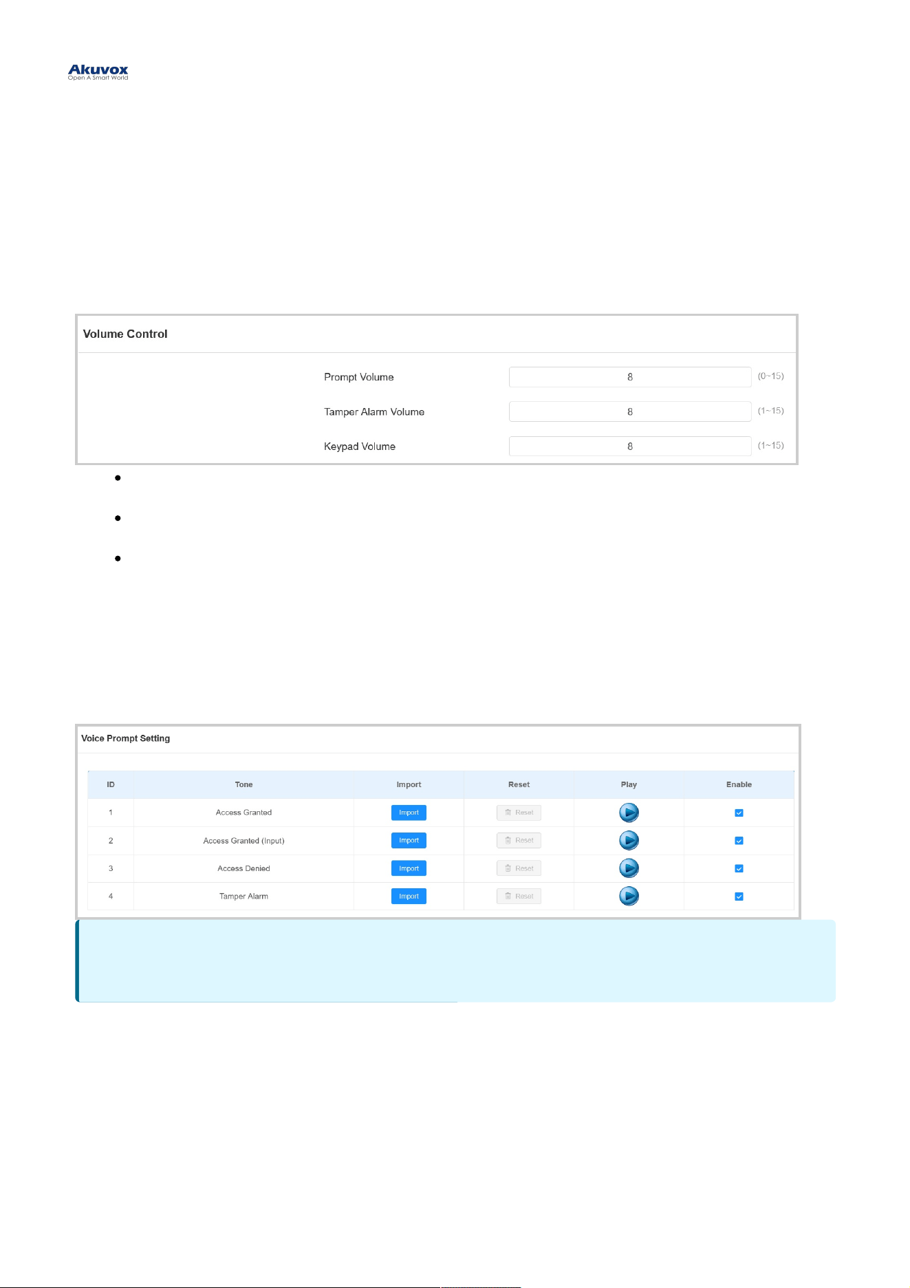
Volume and tone configuration include keypad volume, prompt volume, tamper alarm volume, and open-door tone
configuration.
To set it up, go to Device > Audio > Volume ControlDevice > Audio > Volume Control interface.
Prompt VolumePrompt Volume: Set the voice prompt volume. The default volume is 8.
Tamper Alarm VolumeTamper Alarm Volume: Set the volume when the tamper alarm is triggered. The default volume is 8.
Keypad VolumeKeypad Volume: Set the volume when pressing the keypad. The default volume is 8.
Voice Prompts UploadVoice Prompts Upload
You can customize and upload various voice prompts to the device.
To set it up, go to Device > Audio > Voice Prompt SettingDevice > Audio > Voice Prompt Setting interface.
Volume and Tone ConfigurationVolume and Tone Configuration
NoteNote
File Format: WAV; Size: < 200KB; Sample Rate:16000; Bits: 16
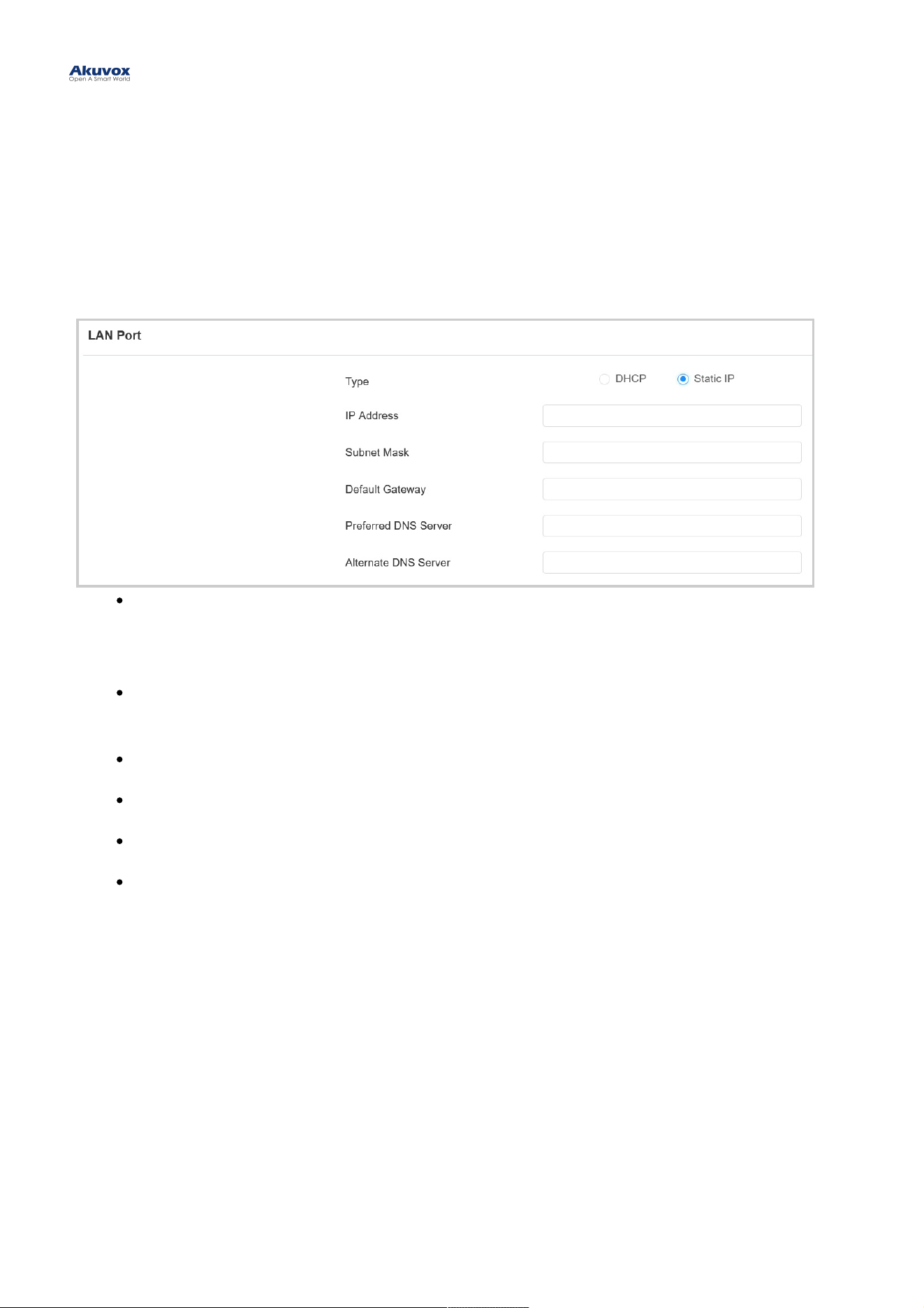
To ensure normal functioning, make sure that the device has its IP address set correctly or obtained automatically from
the DHCP server.
To set it up, go to Network > BasicNetwork > Basic interface.
DHCPDHCP : DHCP mode is the default network connection. If the DHCP mode is selected, the access control
terminal will be assigned by the DHCP server with IP address, subnet mask, default gateway, and DNS server
address automatically.
Static IPStatic IP : When static IP mode is selected, the IP address, subnet mask, default gateway, and DNS server
address should be configured according to the network environment.
IP AddressIP Address : Set up the IP address when the static IP mode is selected.
Subnet MaskSubnet Mask: Set up the subnet mask according to the actual network environment.
Default GatewayDefault Gateway: Set up the correct gateway according to the IP address.
Preferred/Alternate DNS ServerPreferred/Alternate DNS Server: Set up the preferred or alternate Domain Name Server(DNS) server
according to the actual network environment. The preferred DNS server is the primary server while the
alternate DNS server is the secondary one. The secondary server is for backup.
Network SettingNetwork Setting
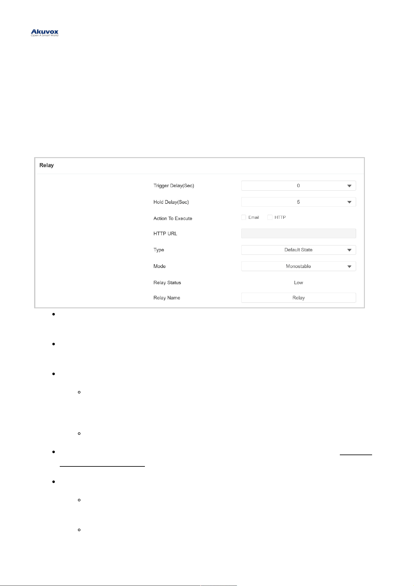
You can configure the relay switch(es) for door access on the web interface.
Relay SwitchRelay Switch
To set up the relay, go to Access Control > Relay > RelayAccess Control > Relay > Relay interface.
Trigger Delay(Sec)Trigger Delay(Sec): Set the delay time before the relay triggers. For example, if set to 5 seconds, the relay
activates 5 seconds after pressing the Unlock button.
Hold Delay(Sec)Hold Delay(Sec): Determine how long the relay stays activated. For example, if set to 5 seconds, the relay
remains to be opened for 5 seconds before closing.
Action to ExecuteAction to Execute: Check the action to be executed when the relay is triggered.
HTTPHTTP : When triggered, the HTTP message can be captured and displayed in the corresponding
packets. To utilize this feature, enable the HTTP server and enter the message content in the
designated box below.
EmailEmail: Send a screenshot to the preconfigured Email address.
HTTP URLHTTP URL: Enter the HTTP message if selecting HTTP as the action to execute. The format is http://HTTP
server’s IP/Message content.
TypeType : Determine the interpretation of the Relay Status regarding the state of the door:
Default StateDefault State: A “Low” status in the Relay Status field indicates that the door is closed, while “High”
indicates that it is opened.
Invert StateInvert State: A “Low” status in the Relay Status field indicates an opened door, while “High”
indicates a closed one.
Relay SettingRelay Setting
ModeMode : Specify the conditions for automatically resetting the relay status.
MonostableMonostable: The relay status resets automatically within the relay delay time after activation.
BistableBistable: The relay status resets upon triggering the relay again.
Relay StatusRelay Status: Indicate the states of the relay, which are normally opened and closed. By default, it shows low
for normally closed(NC) and high for Normally Open(NO).
Relay NameRelay Name: Assign a distinct name for identification purposes.
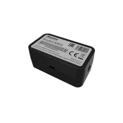
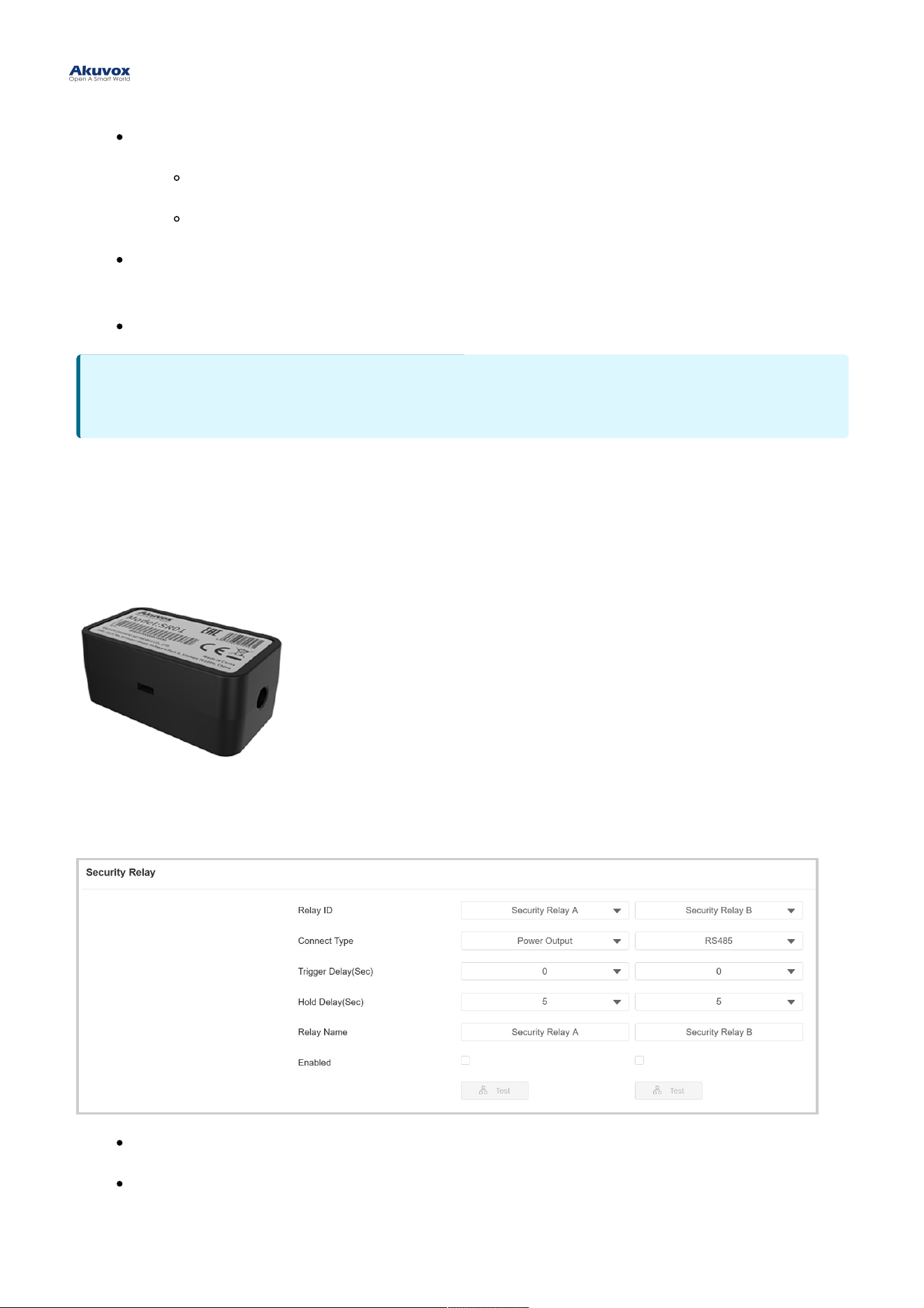
Security RelaySecurity Relay
The Security Relay, known as Akuvox SR01, is a product designed to bolster access security by preventing
unauthorized forced entry attempts. Installed inside the door, it directly governs the door opening mechanism, ensuring
that the door remains secure even in the event of damage to the door phone.
To set it up, go to Access Control > Relay > Security RelayAccess Control > Relay > Security Relay interface.
Relay IDRelay ID: The specific relay for door access.
Connect TypeConnect Type: The security relay connects to the door phone using Power Output or RS485.
NoteNote
External devices connected to the relay require separate power adapters.
Trigger Delay(Sec)Trigger Delay(Sec): Set the delay time before the relay triggers. For example, if set to 5 seconds, the relay
activates 5 seconds after pressing the Unlock button.
Hold Delay(Sec)Hold Delay(Sec): Determine how long the relay stays activated. For example, if set to 5 seconds, the relay
remains to be opened for 5 seconds before closing.
Relay NameRelay Name: Name the security relay. The name can be displayed in door opening logs. When connecting to
the SmartPlus Cloud, the Cloud server will automatically assign the relay name.
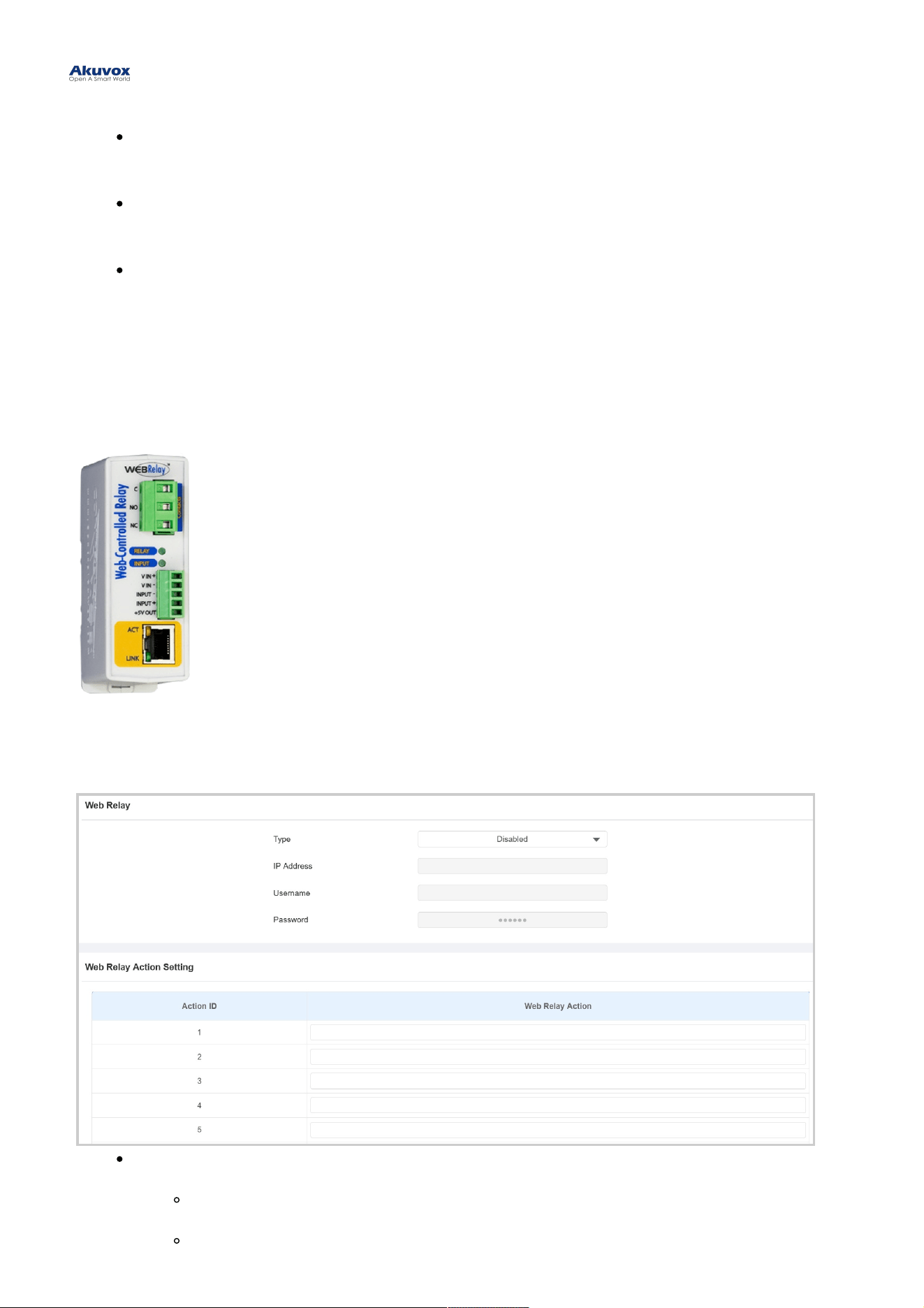
Web RelayWeb Relay
A web relay has a built-in web server and can be controlled via the Internet or a local network. The door phone can use
a web relay to either control a local relay, or a remote relay somewhere else on the network.
To set it up, go to Access Control > Web RelayAccess Control > Web Relay interface.
TypeType : Determine the type of relay activated when employing door access methods for entry.
DisabledDisabled: Only activate the local relay.
Web RelayWeb Relay: Only activate the web relay.

Local Relay+Web RelayLocal Relay+Web Relay: Activate both the local relay and web relay. Typically, the local relay is
triggered first, followed by the web relay to execute their pre-configured actions.
IP AddressIP Address : The web relay IP address provided by the web relay manufacturer.
UsernameUsername: The user name provided by the web relay manufacturer.
PasswordPassword: The manufacturer-provided authentication key for the web relay. Authentication occurs via HTTP.
Leaving the Password field blank indicates non-use of HTTP authentication. You can define the password
using HTTP GET in the Web Relay Action field.
Web Relay ActionWeb Relay Action: Configure the actions to be performed by the web relay upon triggering. Enter the
manufacturer-provided URLs for various actions, with up to 50 commands.
NOTENOTE
If the URL includes full HTTP content (e.g., http://admin:admin@192.168.1.2/state.xml?relayState=2), it doesn't
rely on the IP address that you entered above. However, if the URL is simpler (e.g., "state.xml?relayState=2"),
the relay uses the entered IP address.
Door Access ScheduleDoor Access Schedule
A door access schedule lets you decide who can open the door and when. It applies to both individuals and groups,
ensuring that users within the schedule can only open the door using the authorized method during designated time
periods.
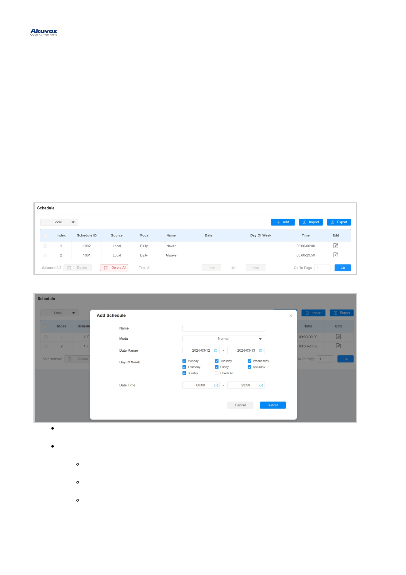
Create Door Access ScheduleCreate Door Access Schedule
To create a door access schedule, go to the Setting > ScheduleSetting > Schedule interface.
Click +Add+Add to create a schedule.
NameName: Name the schedule.
ModeMode :
NormalNormal: Set the schedule based on the month, week, and day. It is used for a long period schedule.
WeeklyWeekly: Set the schedule based on the week.
DailyDaily: Set the schedule based on 24 hours a day.
Import and Export Door Access ScheduleImport and Export Door Access Schedule
Door Access Schedule ManagementDoor Access Schedule Management
You can create door access schedules one by one or in bulk. You can export the current schedule file, edit it or add
more schedules following the format, and import the new file to the desired devices. This helps you manage your door
access schedules easily.
To set it up, go to the Setting > ScheduleSetting > Schedule interface. The export file is in TGZTGZ format. The import file should be in
XMLXML format.
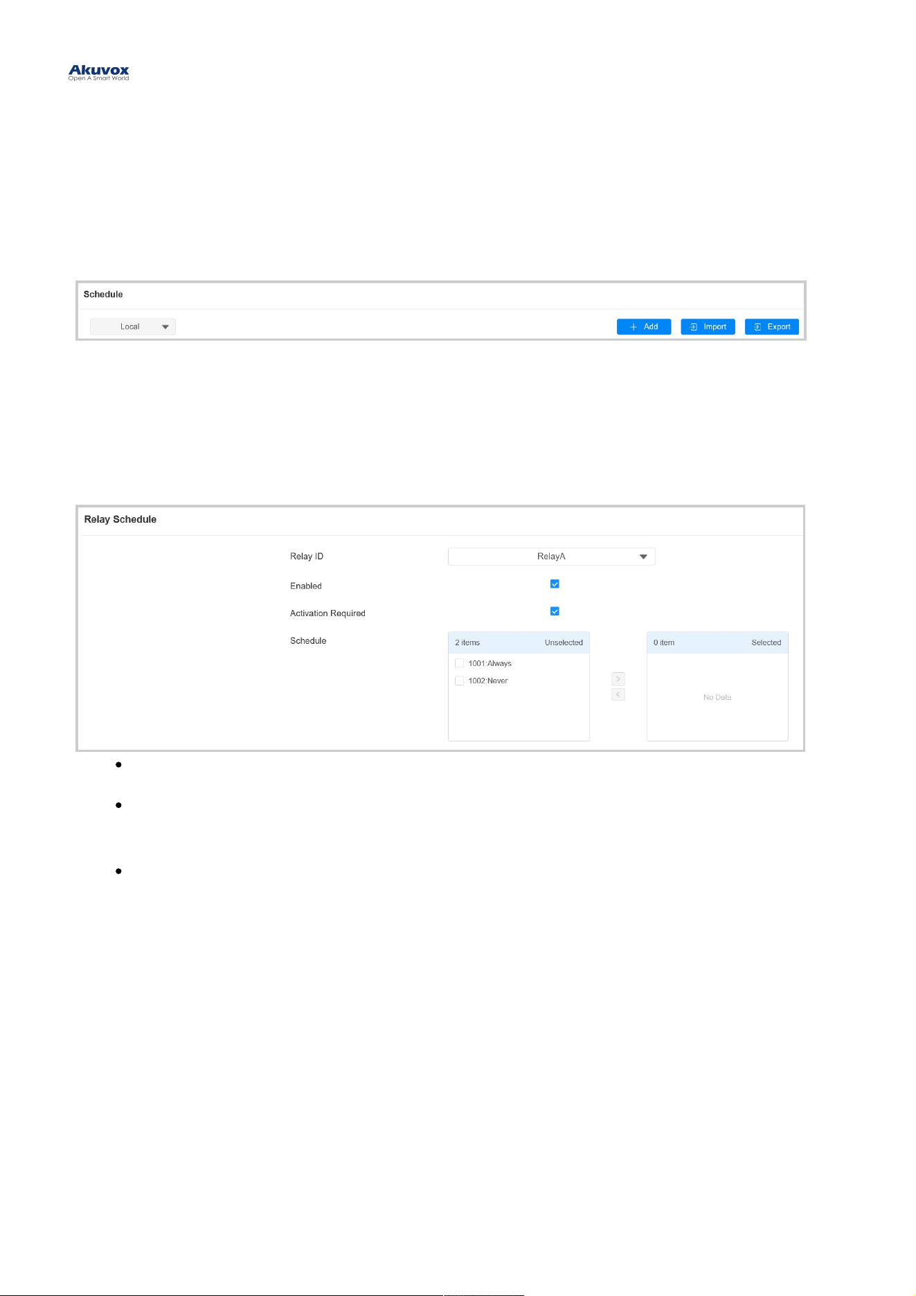
Relay ScheduleRelay Schedule
The relay schedule allows you to set a specific relay to always open at a certain time. This is helpful for situations like
keeping the gate open after school or keeping the door open during work hours.
To set it up, go to Access Control > Relay > Relay ScheduleAccess Control > Relay > Relay Schedule interface.
Relay IDRelay ID: Specify the relay you need to set up.
Activation RequiredActivation Required: It means only after the relay is triggered successfully for the first time, can it be
triggered by device-supported access methods later.
Schedule:Schedule: Assign particular door access schedules to the chosen relay. Simply move them to the Selected
Schedules box.
For instructions on creating schedules, kindly consult the Create Door Access Schedule section.
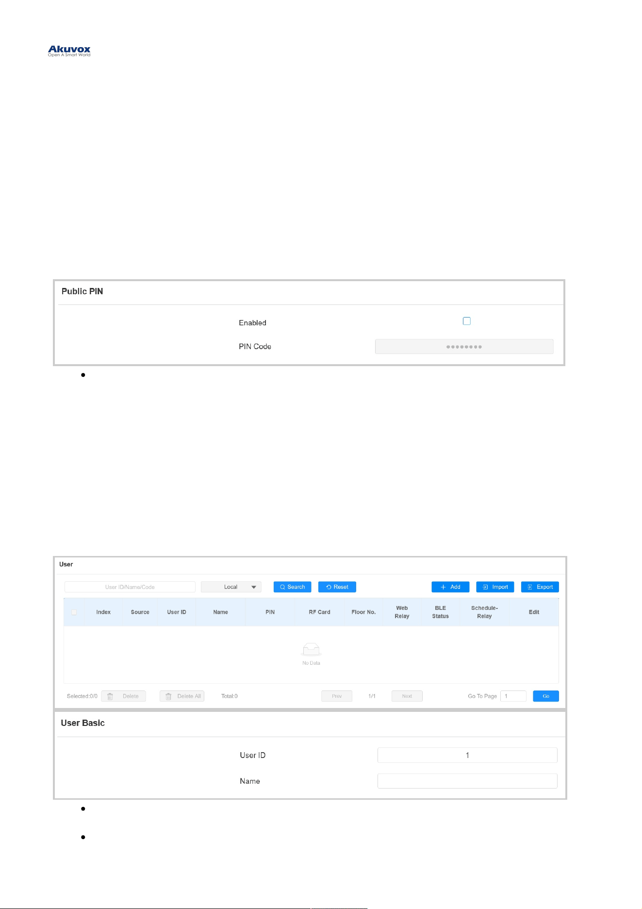
Public PIN Code for Door UnlockPublic PIN Code for Door Unlock
There are two types of PIN codes for door access: public and private. A private PIN is unique to each user, while the
public one is shared by residents in the same building or complex. You can create and modify both the public and
private PIN codes.
To set up the public PIN code, go to Access Control > PIN Setting > Public PINAccess Control > PIN Setting > Public PIN interface.
PIN CodePIN Code: Set a 3-8 digit PIN code accessible for universal use.
User-specific Access MethodsUser-specific Access Methods
The private PIN code, RF card, QR code, and Bluetooth setting should be assigned to a particular user for door
opening.
When adding a user, you can also customize settings such as defining the door access schedule to determine when
the code is valid and specifying which relay to open.
To add a user, go to Directory > UserDirectory > User interface and Click +Add+Add.
User IDUser ID: The unique identification number assigned to the user.
NameName: The name of this user.
Door Unlock ConfigurationDoor Unlock Configuration
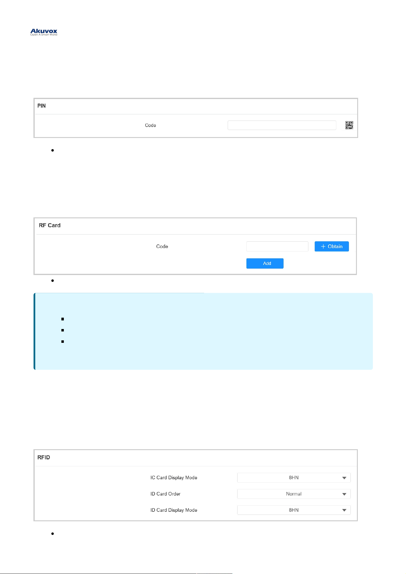
Unlock by Private PIN CodeUnlock by Private PIN Code
On the Directory > User > +Add Directory > User > +Add interface, scroll to the PINPIN section.
CodeCode : Set a 2-8 digit PIN code solely for the use of this user. Each user can only be assigned a single PIN
code.
Unlock by RF CardUnlock by RF Card
On the Directory > User > +Add Directory > User > +Add interface, scroll to the RF CardRF Card section.
CodeCode : The card number that the card reader reads.
RF Card Code FormatRF Card Code Format
To integrate the RF card door access with the third-party intercom system, you need to match the RF card code format
with the one used by the third-party system.
To set it up, go to Access Control > Card Setting > RFIDAccess Control > Card Setting > RFID interface.
IC/ID Card Display ModeIC/ID Card Display Mode: Set the card number format from the provided options. The default format in
the device is 8HN.
Note:Note:
Each user can have a maximum of 5 cards added.
The device allows to add 20,000 users.
RF cards operating at 13.56 MHz and 125 KHz frequencies are compatible with the door phone for
access.
ID Card OrderID Card Order: Set the ID card reading mode between Normal and Reversed.
Unlock by BluetoothUnlock by Bluetooth
A08 supports opening the door via Bluetooth-enabled My MobileKey or SmartPlus App. Users can either open the
door with the apps in their pockets or wave their phones towards the door phone as they get closer to the door.
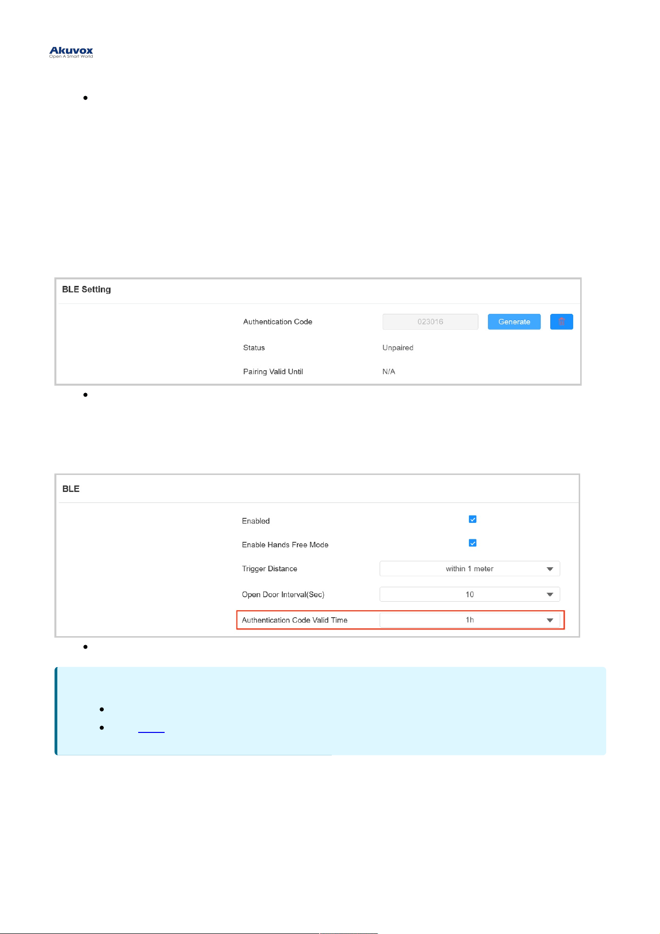
Unlock via My MobileKeyUnlock via My MobileKey
On the Directory > User > +Add Directory > User > +Add interface, scroll to the BLE SettingBLE Setting section.
Authentication CodeAuthentication Code: Click GenerateGenerate to generate a 6-digit verification code.
You can set up the pairing valid time within which users need to finish the pairing.
To set it up, go to Access Control > BLE > BLEAccess Control > BLE > BLE interface.
Authentication Code Valid TimeAuthentication Code Valid Time: Set the time from 15 minutes to 24 hours.
Unlock via SmartPlus AppUnlock via SmartPlus App
To open the door via SmartPlus App, the device should be connected to the SmartPlus Cloud.
To set up Bluetooth unlock, go to Access Control > BLE > BLEAccess Control > BLE > BLE interface.
NoteNote
Only A08S supports this feature.
Click here here to see detailed configuration steps.
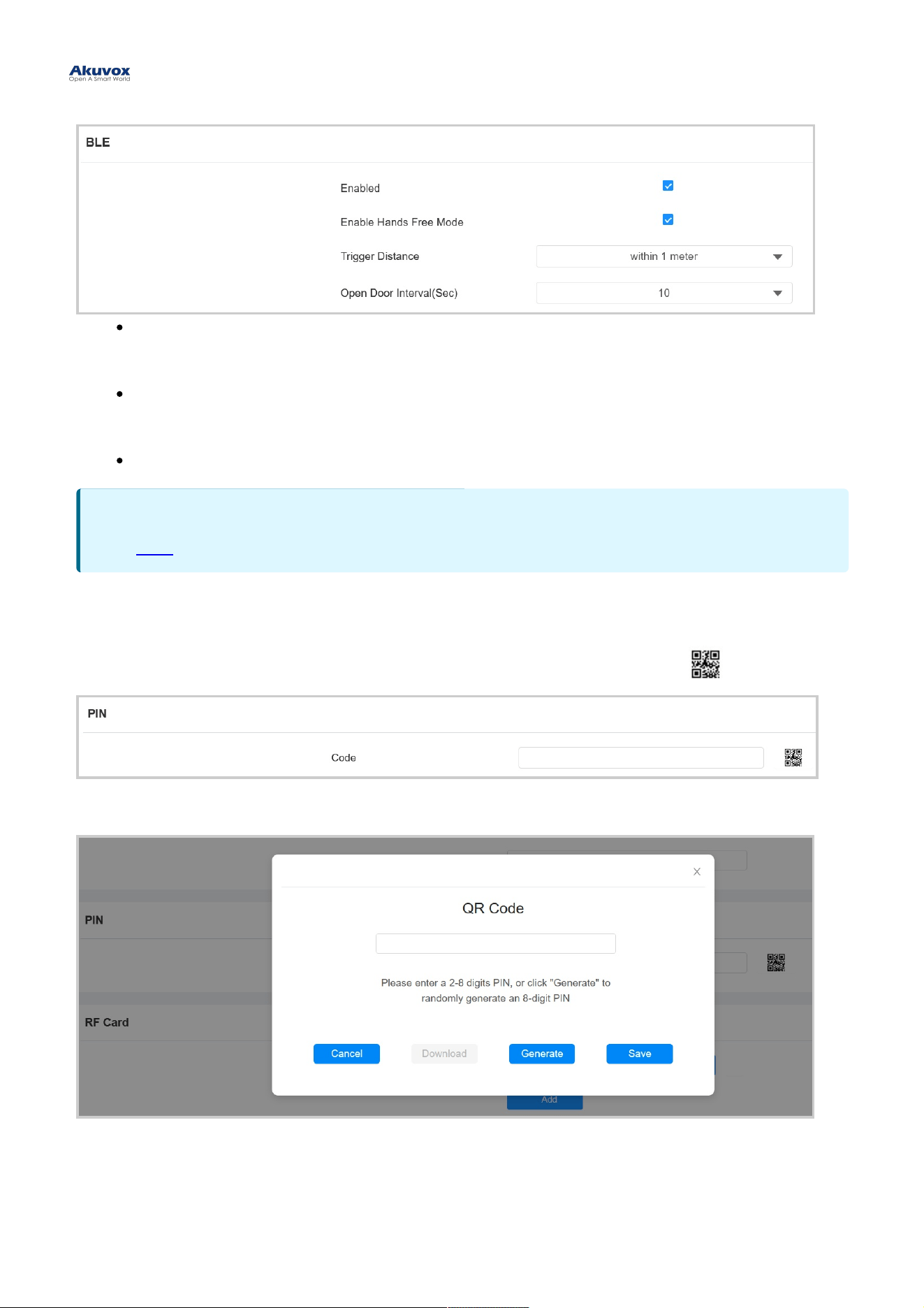
Enable Hands Free ModeEnable Hands Free Mode: If enabled, users can gain door access hands-free. If disabled, users have to
wave their hands near the device to open doors.
Trigger DistanceTrigger Distance : Set the triggering distance of the Bluetooth for the door access. You select Within 1
Meter, Between 1 to 2 Meters, and More Than 2 Meters. The trigger distance is 3 meters maximum.
Open Door IntervalOpen Door Interval: Set the time interval between consecutive Bluetooth door access attempts.
Unlock by QR CodeUnlock by QR Code
On the Directory > User > +Add Directory > User > +Add interface, scroll to the PINPIN section. Click the QR code icon .
Click GenerateGenerate to generate the QR code with an 8-digit PIN.
NoteNote
Click here here to see detailed configuration steps.
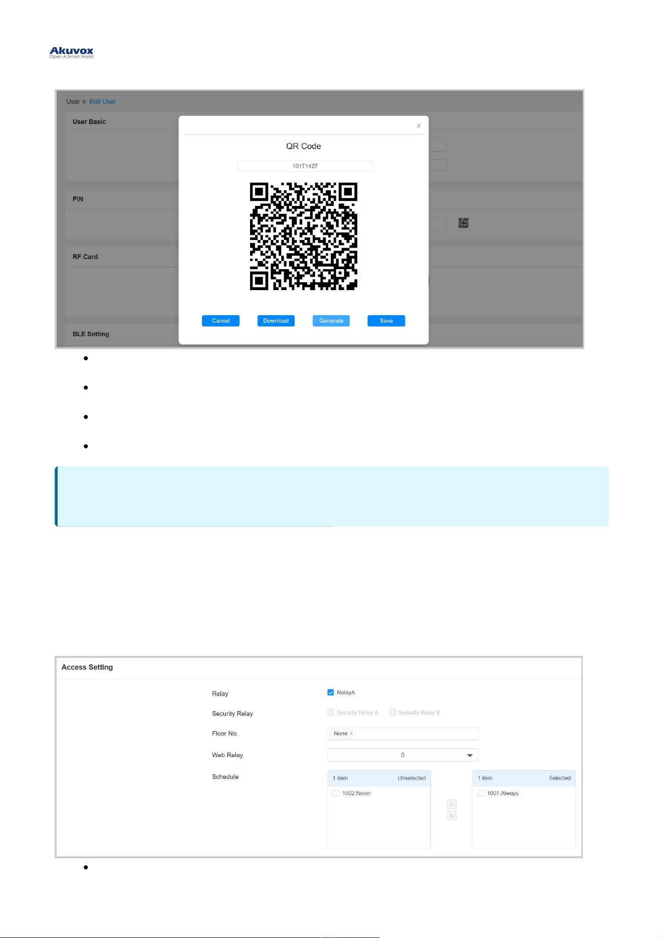
CancelCancel: Click to return to the user editing interface. The QR code and the PIN code will not be saved.
DownloadDownload: Click to save the QR code to your PC.
GenerateGenerate: Click to generate another QR code and PIN code.
SaveSave: Click to return to the user editing interface and save the codes.
Access SettingAccess Setting
You can customize access settings such as defining the door access schedule to determine when the code is valid
and specifying which relay to open.
On the Directory > User > +Add Directory > User > +Add interface, scroll to the Access SettingAccess Setting section.
RelayRelay: Specify the relay(s) to be unlocked using the door opening methods assigned to the user.
NoteNote
Only A08S supports this feature.
Security RelaySecurity Relay: Select the security relay that you’ve configured on the Security Relay interface.
Floor No.Floor No. : Specify the accessible floor(s) to the user via the elevator.
Web RelayWeb Relay: Specify the ID of web relay action commands that you’ve configured on the Web Relay interface.
A default value of 0 indicates that the web relay will not be triggered.
ScheduleSchedule: Grant the user access to open designated doors during preset periods by relocating the desired
schedule(s) from the left box to the right one. Besides custom schedules, there are 2 default options:
AlwaysAlways: Allows door opening without limitations on door open counts during the valid period.
NeverNever: Prohibits door opening.
Unlock by NFCUnlock by NFC
NFC (Near Field Communication) is a popular way for door access. It uses radio waves for data transmission
interaction. The device can be unlocked by NFC. You can keep the mobile phone closer to the door phone for door
access.
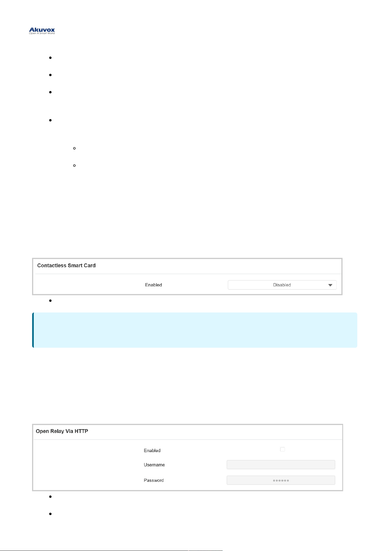
To set it up, go to Access Control > Card Setting > Contactless Smart CardAccess Control > Card Setting > Contactless Smart Card interface.
EnabledEnabled: Select from Disabled, NFC, Felica, and NFC & Felica.
Unlock by HTTP CommandUnlock by HTTP Command
You can unlock the door remotely without approaching the device physically for door entry by typing in the created
HTTP command (URL) on the web browser to trigger the relay when you are not available by the door for door entry.
To set it up, go to Access Control > Relay > Open Relay Via HTTPAccess Control > Relay > Open Relay Via HTTP interface.
UsernameUsername: Set a username for authentication in HTTP command URLs.
PasswordPassword: Set a password for authentication in HTTP command URLs.
NoteNote
The NFC feature is not available on iPhones.
Unlock by Exit ButtonUnlock by Exit Button
When you need to open the door from inside using the exit button installed by the door, you can configure the access
control terminal Input to trigger the relay for the door access.When users need to open the door from inside by
pressing the Exit button, you need to set up the Input terminal that matches the Exit button to activate the relay for the
door access.
To set it up, go to Access Control > Input Access Control > Input interface.
EnabledEnabled: To use a specific input interface.
Trigger Electrical LevelTrigger Electrical Level: Set the input interface to trigger at low or high electrical level.
Action To ExecuteAction To Execute: Set the desired actions that occur when the specific Input interface is triggered.
EmailEmail: Send a screenshot to the preconfigured Email address.
HTTPHTTP : When triggered, the HTTP message can be captured and displayed in the corresponding
packets. To utilize this feature, enable the HTTP server and enter the message content in the
designated box below.
HTTP URLHTTP URL: Enter the HTTP message if selecting HTTP as the action to execute. The format is http://HTTP
server’s IP/Message content.
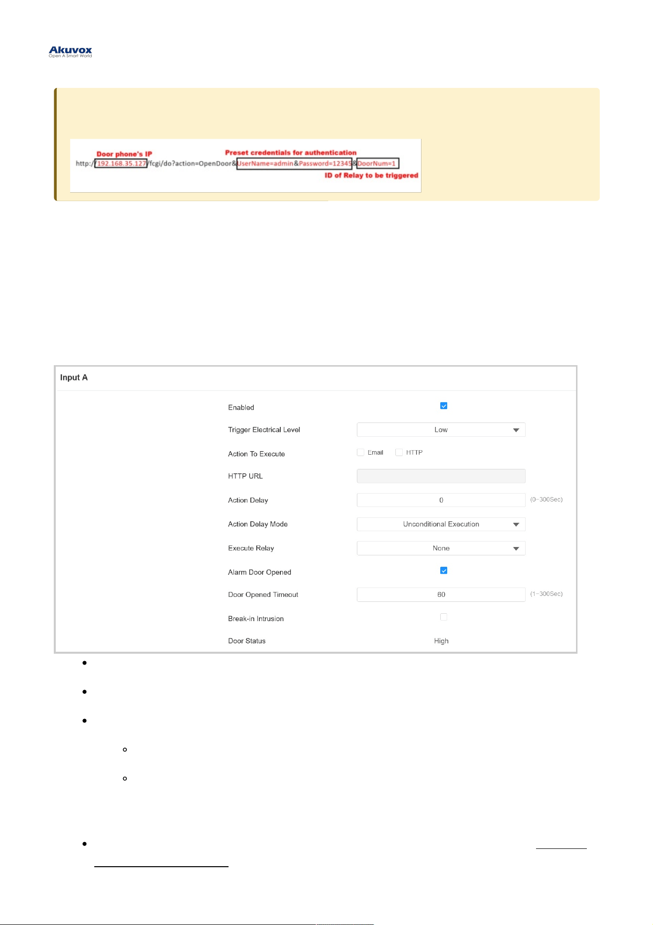
Tip:Tip:
Here is an HTTP command URL example for relay triggering.
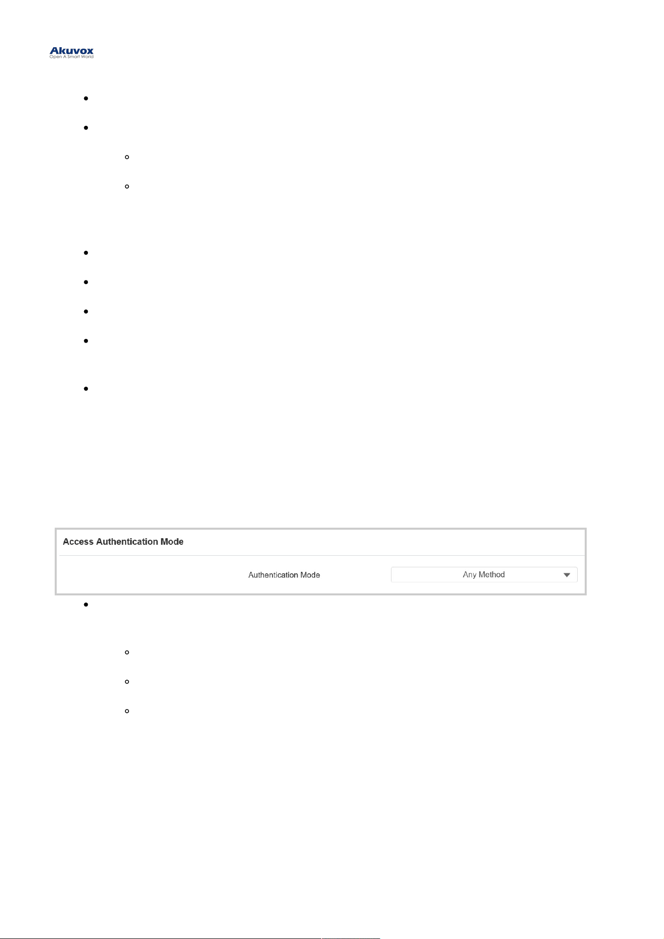
Action DelayAction Delay: Specify how many seconds to delay executing the preconfigured actions.
Action Delay ModeAction Delay Mode:
Unconditional ExecutionUnconditional Execution: The action will be carried out when the input is triggered.
Execute If Input Still TriggeredExecute If Input Still Triggered: The action will be carried out when the input stays triggered. For
example, if the door stays open after triggering input, an action such as an email will be sent to notify
the receiver.
Execute RelayExecute Relay: Specify the relay to be triggered by the actions.
Alarm Door OpenedAlarm Door Opened: Decide whether to enable Door Opened Timeout.
Door Opened TimeoutDoor Opened Timeout: Set the time limit for the door to stay open.
Break-in IntrusionBreak-in Intrusion: Activate an alarm when the door is forcibly or illegally opened. Only by checking off this
option can the alarm be turned off once triggered.
Door StatusDoor Status: Display the status of the input signal.
Access Authentication ModeAccess Authentication Mode
The device allows dual authentication for door access, using the combination of PIN code and RF card. When the
mode is set up, users must unlock the door in the order of the chosen methods.
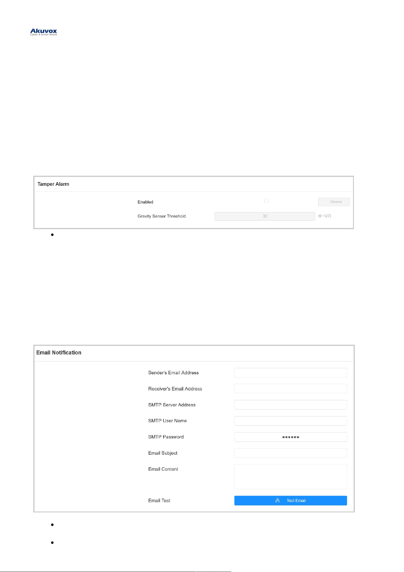
To set it up, go to Access Control > Relay > Access Authentication ModeAccess Control > Relay > Access Authentication Mode interface.
Authentication ModeAuthentication Mode: Determine how to unlock the door using different methods. Please note that the order
of the two-factor authentication matters.
Any MethodAny Method : Allow all access methods.
PIN + RF CardPIN + RF Card: Enter the PIN code first, then swipe the RF card.
RF Card + PINRF Card + PIN: Swipe the RF card first, then enter the PIN code.
Tamper AlarmTamper Alarm
The tamper alarm function prevents anyone from removing the devices without permission. It does this by setting off
the tamper alarm and making calls to a designated location, when the door phone detects a change in its gravity value
from the original one.
To set it up, go to System > Security > Tamper AlarmSystem > Security > Tamper Alarm interface.
Gravity Sensor ThresholdGravity Sensor Threshold: The threshold for gravity sensory sensitivity. The lower the value is, the more
sensitive the sensor will be. It is 32 by default.
Security NotificationSecurity Notification
Email NotificationEmail Notification
Set up email notifications to receive screenshots of unusual motion from the device.
Go to Setting > Action > Email NotificationSetting > Action > Email Notification interface.
SMTP Server AddressSMTP Server Address : The SMTP server address of the sender.
SMTP User NameSMTP User Name: The SMTP username is usually the same as the sender's email address.
SecuritySecurity

SMTP PasswordSMTP Password: The password of the SMTP service is the same as the sender's email address.
Email TestEmail Test: Used to test whether the email can be sent and received.
Action URLAction URL
You can use the device to send specific HTTP URL commands to the HTTP server for certain actions. These actions
will be triggered when the relay status, input status, PIN code, or RF card access changes.
Akuvox Action URL:Akuvox Action URL:
No Event Parameter format Example
1 Make Call $remote Http://server ip/ Callnumber=$remote
2 Hang Up $remote Http://server ip/ Callnumber=$remote
3 Relay Triggered $relay1status Http://server ip/
relaytrigger=$relay1status
4 Relay Closed $relay1status Http://server ip/
relayclose=$relay1status
5 Input Triggered $input1status Http://server ip/
inputtrigger=$input1status
6 Input Closed $input1status Http://server ip/
inputclose=$input1status
7 Valid Code Entered $code Http://server ip/
validcode=$code
8 Invalid Code Entered $code Http://server ip/
invalidcode=$code
9 Valid Card Entered $card_sn Http://server ip/
validcard=$card_sn
10 Invalid Card Entered $card_sn Http://server ip/
invalidcard=$card_sn
11 Tamper Alarm Triggered $alarm status Http://server ip/tampertrigger=$alarm
status
For example: http://192.168.16.118/help.xml?
mac=$mac:ip=$ip:model=$model:firmware=$firmware:card_sn=$card_sn
To set it up, go to Setting > Action URLSetting > Action URL interface.
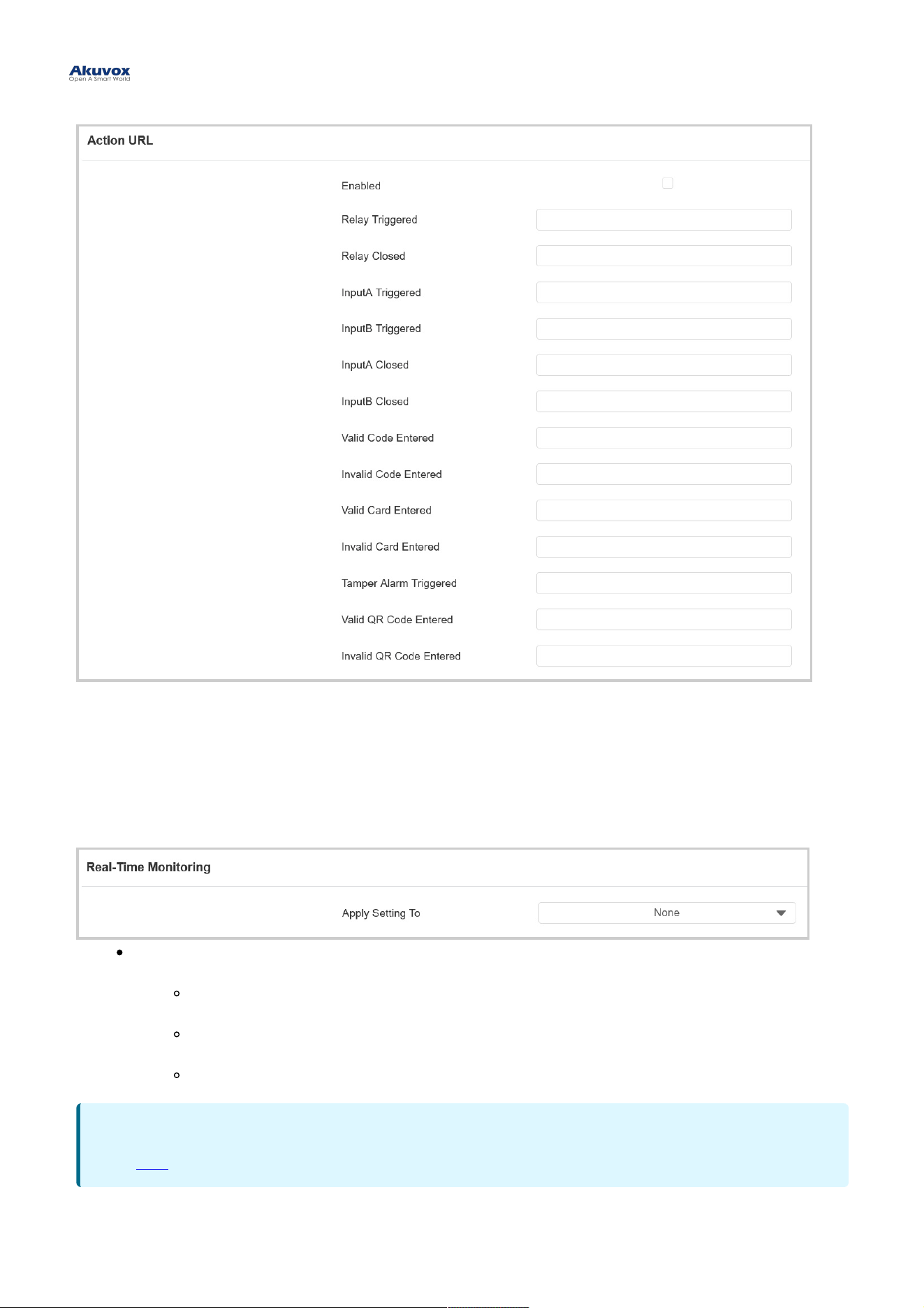
Real-Time MonitoringReal-Time Monitoring
When the device is connected to SmartPlus Cloud or ACMS, the door status can be displayed on the SmartPlus
platform or ACMS.
To set it up, go to System > Security > Real-Time MonitoringSystem > Security > Real-Time Monitoring interface.
Apply Setting ToApply Setting To :
NoneNone: Not display door status.
InputInput: the door is opened by triggering input.
RelayRelay: the door is opened by triggering the relay.
NoteNote
Click herehere to see the detailed configuration steps.
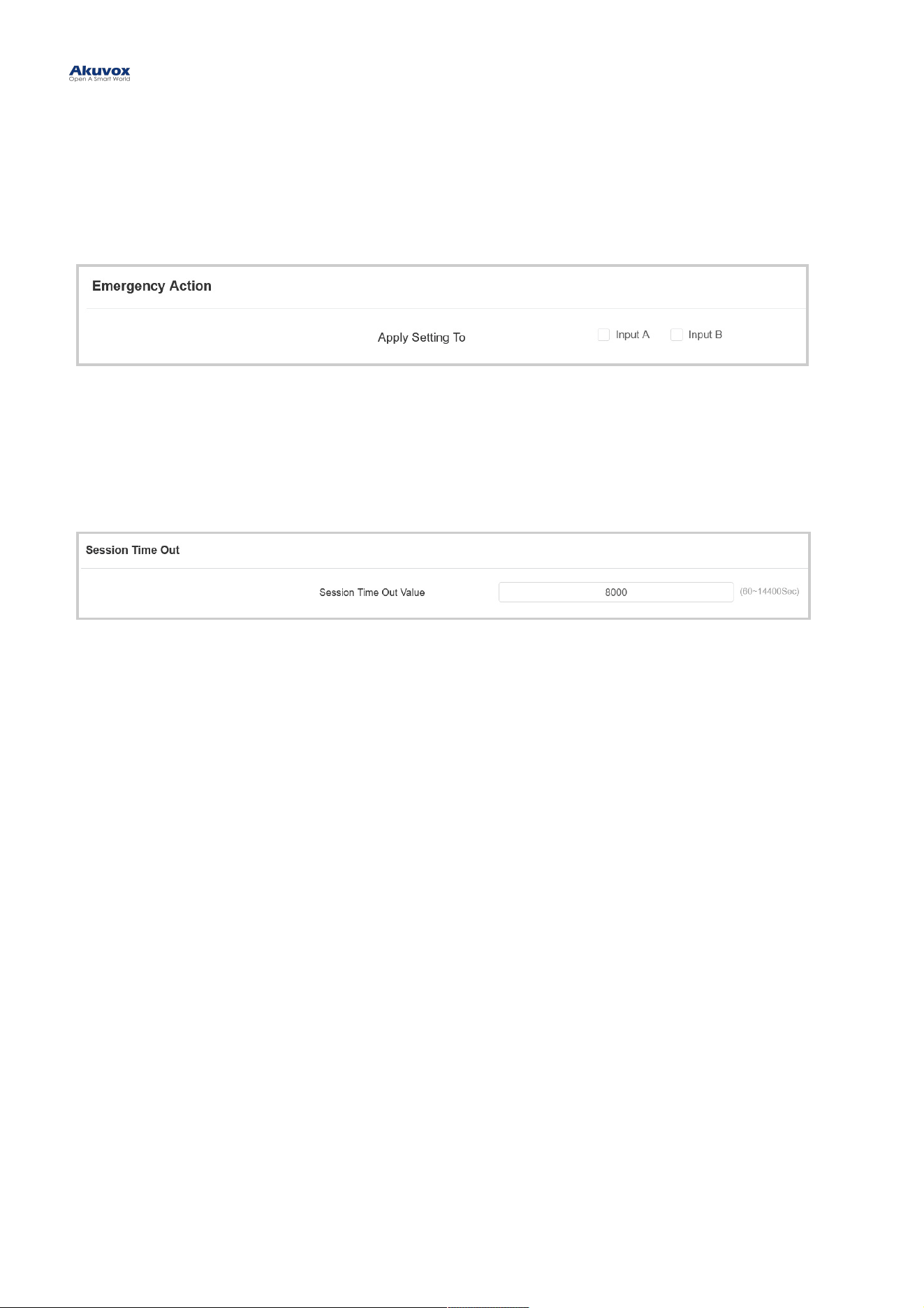
Emergency ActionEmergency Action
This feature works with Akuvox SmartPlus Cloud. It keeps the door open when an emergency happens.
To set it up, go to System > Security > Emergency ActionSystem > Security > Emergency Action interface.
Web Interface Automatic Log-outWeb Interface Automatic Log-out
You can set up the web interface's automatic log-out timing, requiring re-login by entering the user name and the
passwords for security purposes or for the convenience of operation.
To set it up, go to System > Security > Session Time OutSystem > Security > Session Time Out interface.
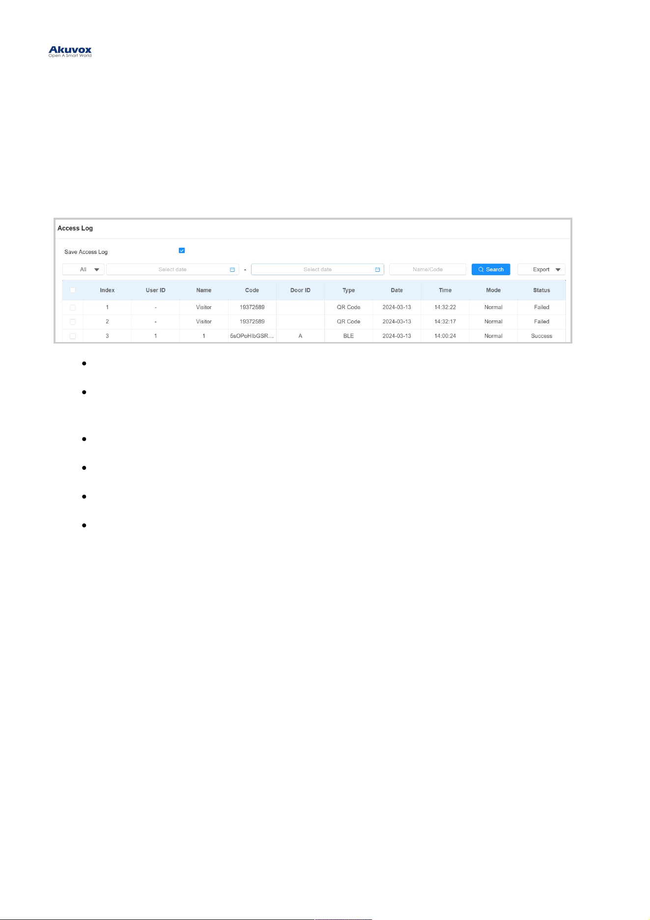
Access LogAccess Log
You can search and check door logs on the device web Status > Access LogStatus > Access Log interface.
Save Access LogSave Access Log: Decide whether to save the door-opening records.
StatusStatus: SuccessSuccess and FailedFailed options represent successful door accesses and failed door accesses
respectively.
TimeTime: Select the specific period of the door logs you want to search, check, or export.
Name/CodeName/Code: Search the log by the username or the PIN code.
Door IDDoor ID: Display the door name.
TypeType : Display the access type such as QR code.
LogsLogs
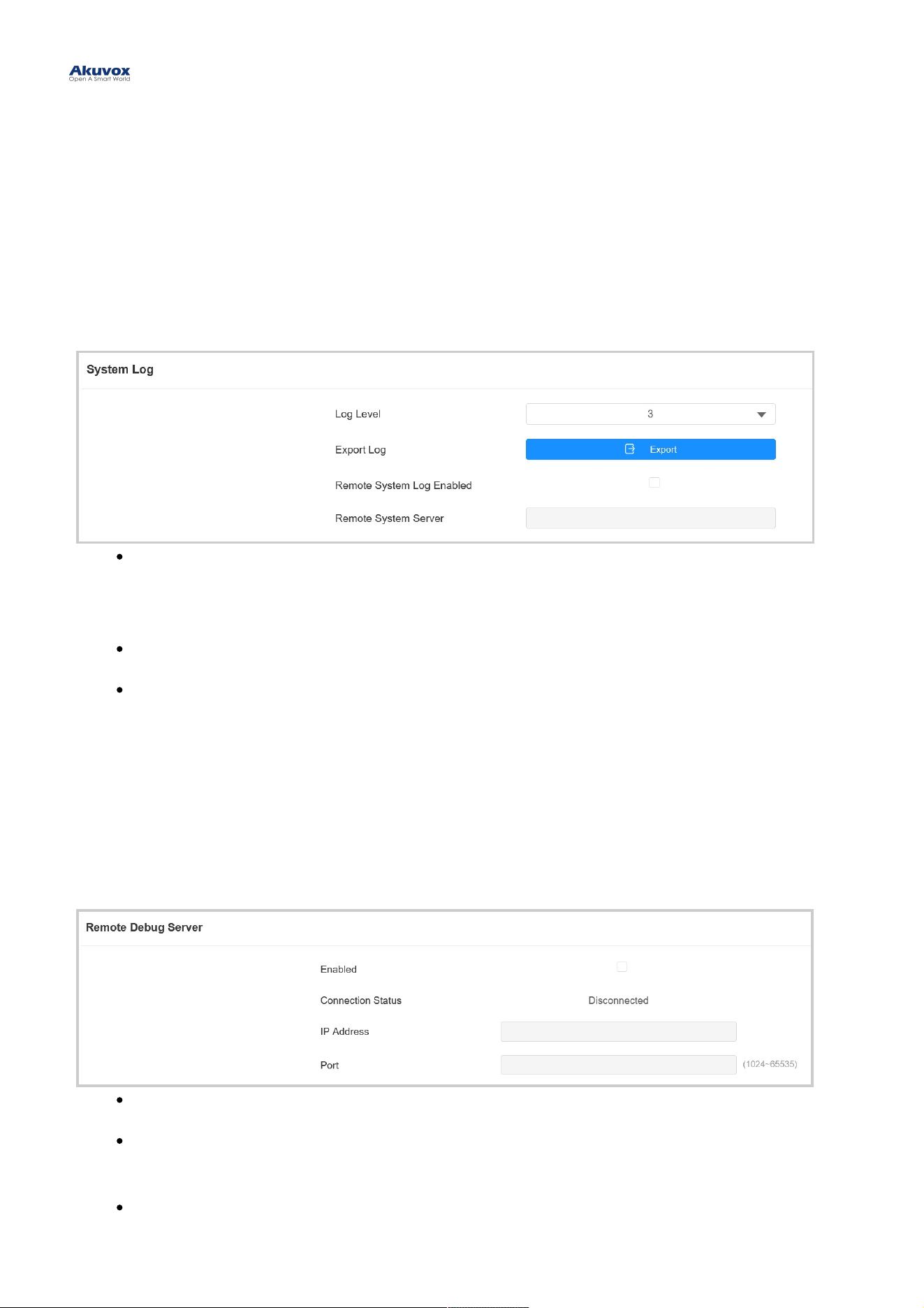
System Log for DebuggingSystem Log for Debugging
System logs can be used for debugging purposes.
To set it up, go to System > Maintenance > System LogSystem > Maintenance > System Log interface.
Log LevelLog Level: Log levels range from 1 to 7. You will be instructed by Akuvox technical staff about the specific log
level to be entered for debugging purposes. The default log level is 3. The higher the level is, the more
complete the log is.
Export LogExport Log: Click the ExportExport tab to export the temporary debug log file to a local PC.
Remote System ServerRemote System Server: Set the remote server address to receive the device log. The remote server
address will be provided by Akuvox technical support.
Remote Debug ServerRemote Debug Server
When the device is having a problem, you can use the remote debug server to access the device log remotely for
debugging purposes.
To set it up, go to System > Maintenance> Remote Debug ServerSystem > Maintenance> Remote Debug Server interface.
Connect StatusConnect Status: Display the remote debug server connection status.
IP AddressIP Address : Set the remote debug server IP address. Please ask the Akuvox technical team for the server IP
address.
PortPort: Set the remote debug server port.
DebugDebug
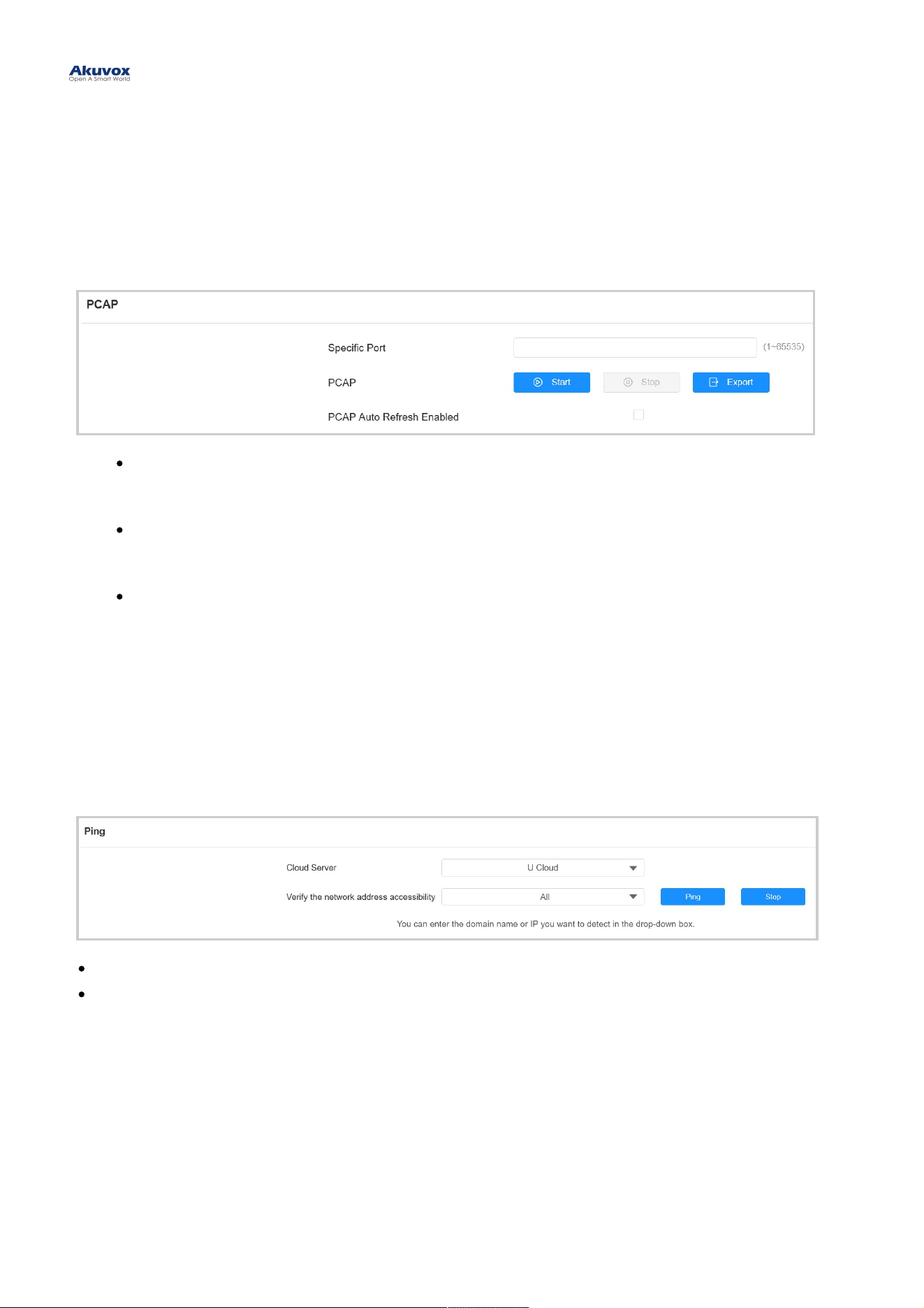
PCAP for DebuggingPCAP for Debugging
PCAP is used to capture the data package going in and out of the devices for debugging and troubleshooting
purposes.
To set it up, go to System > Maintenance > PCAPSystem > Maintenance > PCAP interface.
Specific PortSpecific Port: Select the specific ports from 1-65535 so that only the data packet from the specific port can
be captured. You can leave the field blank by default.
PCAPPCAP : Click the StartStart tab and StopStop tab to capture a certain range of data packets before clicking the
ExportExport tab to export the data packets to your Local PC.
PCAP Auto Refresh EnabledPCAP Auto Refresh Enabled: When enabled, the PCAP will continue to capture data packets even after
the data packets reach their 50M maximum in capacity. When disabled, the PCAP will stop data packet
capturing when the data packets captured reach the maximum capturing capacity of 1MB.
PingPing
The device allows you to verify the accessibility of the target server.
To set it up, go to System > Maintenance > Ping System > Maintenance > Ping interface.
C l o u d Se rve rC l o u d Se rve r: Sel ect t he s erver to be verifi ed.
Ve ri f y t h e ne t wo rk a d dre s s a cce s s i bi l i t yVe ri f y t h e ne t wo rk a d dre s s a cce s s i bi l i t y: Sel ect t he service type.
Akuvox devices can be upgraded on the device web interface.
To upgrade the device, go to System > UpgradeSystem > Upgrade interface.
Firmware UpgradeFirmware Upgrade
NoteNote
Firmware files should be in .rom.rom format for upgrade.
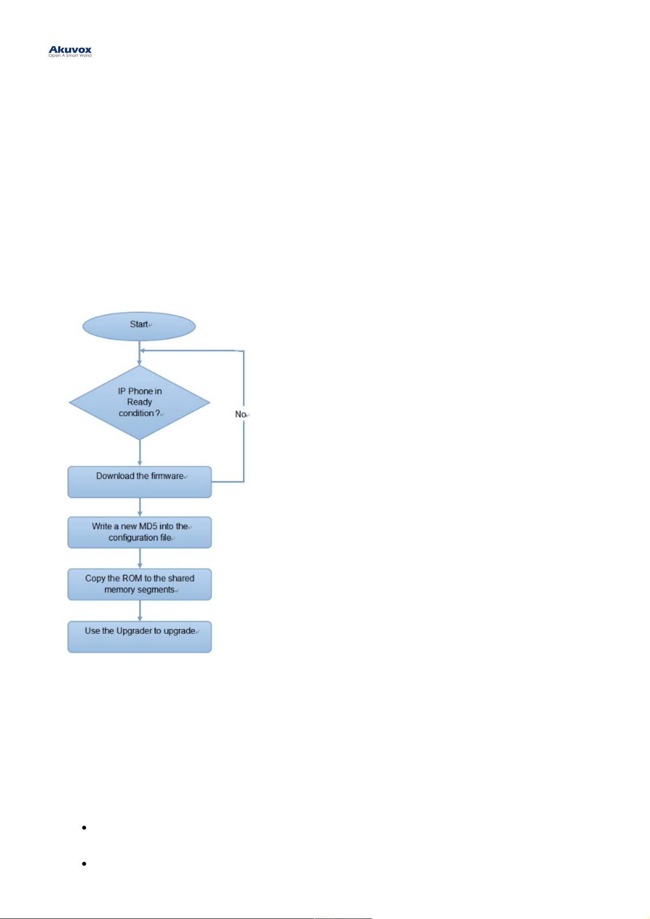
Provisioning PrincipleProvisioning Principle
Auto-provisioning is a feature used to configure or upgrade devices in batch via third-party servers. DHCP, PNP,DHCP, PNP,
TFTP, FTP, and HTTPS TFTP, FTP, and HTTPS are the protocols used by the Akuvox intercom devices to access the URL of the address of
the third-party server which stores configuration files and firmware, which will then be used to update the firmware and
the corresponding parameters on the device.
Please see the flow chart below:Please see the flow chart below:
Introduction to the Configuration Files for Auto-ProvisioningIntroduction to the Configuration Files for Auto-Provisioning
Configuration files have two formats for auto-provisioning. One is the general configuration files used for the general
provisioning and another one is the MAC-based configuration provisioning.
The difference between the two types of configuration files is shown below:The difference between the two types of configuration files is shown below:
GeneralGeneral configurationconfiguration provisioningprovisioning: a general file is stored in a server from which all the related devices
will be able to download the same configuration file to update parameters on the devices. For example, cfg.
MAC-based configuration provisioningMAC-based configuration provisioning : MAC-based configuration files are used for auto-provisioning on
Auto-provisioning via Configuration FileAuto-provisioning via Configuration File
a specific device as distinguished by its unique MAC number. And the configuration files named with the
device MAC number will be matched automatically with the device MAC number before being downloaded for
provisioning on the specific device.
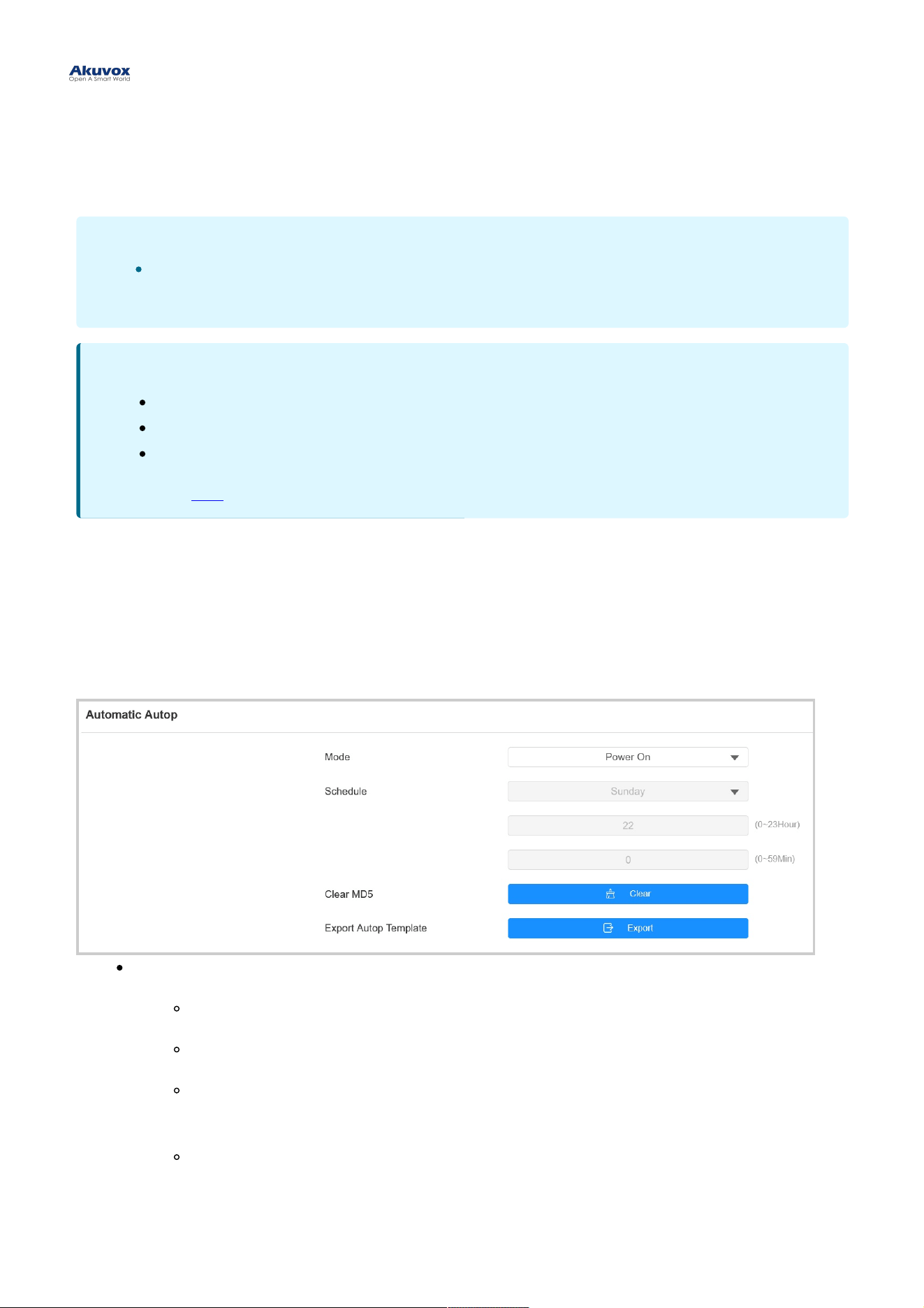
Autop ScheduleAutop Schedule
Akuvox provides you with different Autop methods that enable the device to perform provisioning for itself according to
the schedule.
To set it up, go to System > Auto Provisioning > Automatic AutopSystem > Auto Provisioning > Automatic Autop interface.
ModeMode :
Power OnPower On: The device will perform Autop every time it boots up.
RepeatedlyRepeatedly: The device will perform Autop according to the schedule you set up.
Power On + RepeatedlyPower On + Repeatedly: Combine Power OnPower On mode and RepeatedlyRepeatedly mode that will enable the
device to perform Autop every time it boots up or according to the schedule you set up.
Hourly RepeatHourly Repeat: The device will perform Autop every hour.
Static ProvisioningStatic Provisioning
NoteNote
If a server has these two types of configuration files, then IP devices will first access the general
configuration files before accessing the MAC-based configuration files.
NoteNote
The configuration file should be in CFG format.
The general configuration file for the in-batch provisioning varies by model.
The MAC-based configuration file for the specific device provisioning is named by its MAC address.
You may click herehere to see detailed format and steps.
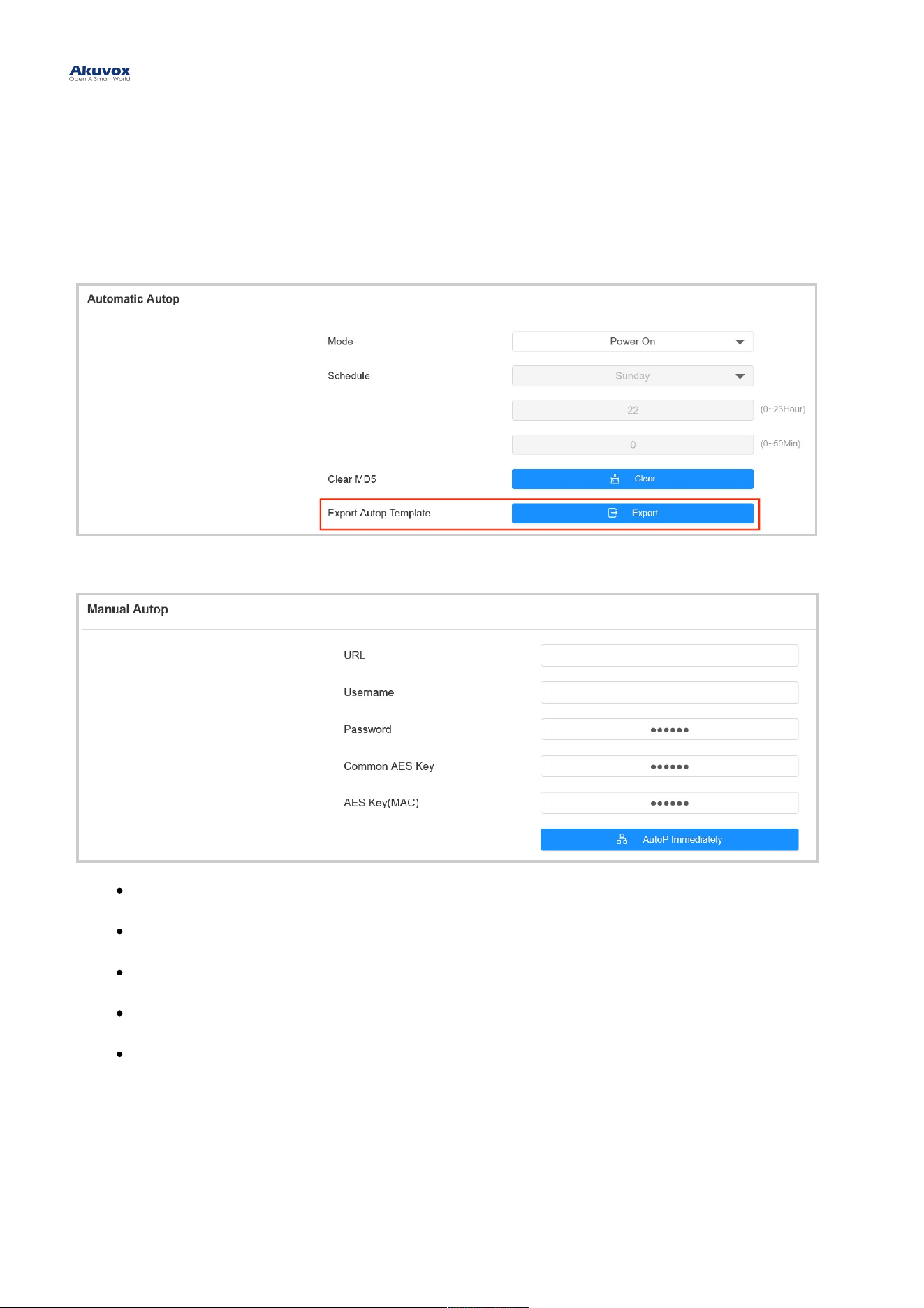
You can manually set up a specific server URL for downloading the firmware or configuration file. If an auto-provision
schedule is set up, the device will perform the auto-provisioning at a specific time according to the auto provision
schedule you set up. In addition, TFTP, FTP, HTTP, and HTTPS are the protocols that can be used for upgrading the
device firmware and configuration.
To set it up, download the template on System > Auto Provisioning > Automatic Autop System > Auto Provisioning > Automatic Autop first.
Set up the Autop server on System > Auto Provisioning > Manual Autop System > Auto Provisioning > Manual Autop interface.
URLURL: Specify the TFTP, HTTP, HTTPS, or FTP server address for the provisioning.
UsernameUsername: Enter the username if the server needs a username to be accessed.
PasswordPassword: Enter the password if the server needs a password to be accessed.
Common AES KeyCommon AES Key: It is used for the intercom to decipher general Autop configuration files.
AES Key (MAC)AES Key (MAC): It is used for the intercom to decipher the MAC-based Autop configuration file.
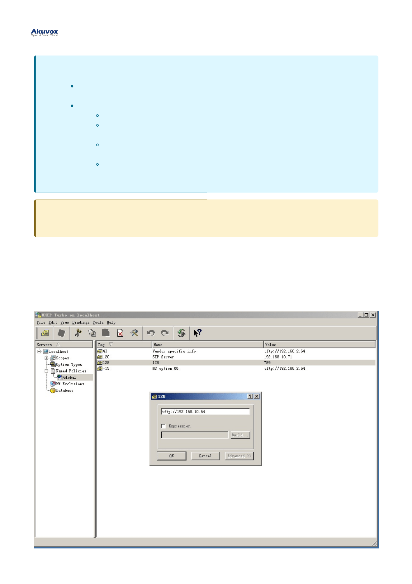
DHCP ProvisioningDHCP Provisioning
Auto-provisioning URL can also be obtained using the DHCP option which allows the device to send a request to a
DHCP server for a specific DHCP option code. If you want to use CustomCustom OptionOption as defined by users with option
codes ranging from 128-255), you are required to configure DHCP Custom Option on the web interface.
NoteNote
AES as one type of encryption should be configured only when the config file is encrypted with
AES.
Server Address Format:
TFTP: tftp://192.168.0.19/
FTP: ftp://192.168.0.19/(allows anonymous login)
ftp://username:password@192.168.0.19/(requires a user name and password)
HTTP: http://192.168.0.19/(use the default port 80)
http://192.168.0.19:8080/(use other ports, such as 8080)
HTTPS: https://192.168.0.19/(use the default port 443)
TipTip
Akuvox does not provide user specified server. Please prepare TFTP/FTP/HTTP/HTTPS server by yourself.
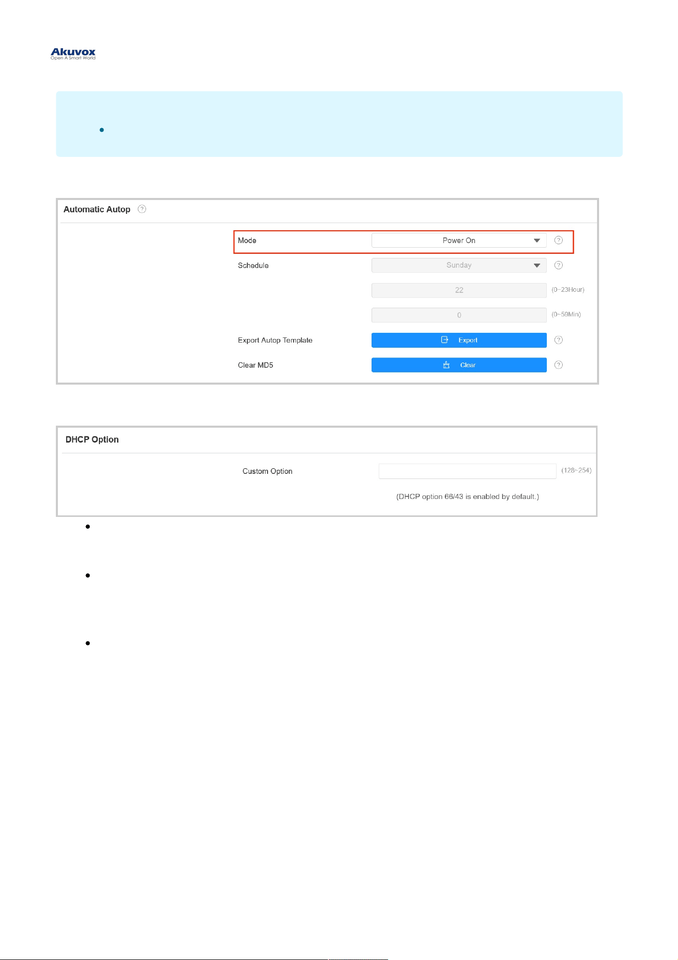
To set up DHCP Autop with Power OnPower On mode, go to the web Upgrade > Advanced > Automatic AutopUpgrade > Advanced > Automatic Autop interface.
To set up the DHCP Option, scroll to the DHCP OptionDHCP Option section.
Custom OptionCustom Option: Enter the DHCP code that matches with corresponding URL so that the device will find the
configuration file server for the configuration or upgrading.
DHCP Option 43DHCP Option 43 : If the device does not get a URL from DHCP Option 66, it will automatically use DHCP
Option 43. This is done within the software and the user does not need to specify this. To make it work, you
need to configure the DHCP server for option 43 with the upgrade server URL in it.
DHCP Option 66DHCP Option 66 : If none of the above is set, the device will automatically use DHCP Option 66 to get the
upgrade server URL. This is done within the software and the user does not need to specify this. To make it
work, you need to configure the DHCP server for option 66 with the upgrade server URL in it.
NoteNote
The Custom Option type must be a string. The value is the URL of TFTP server.
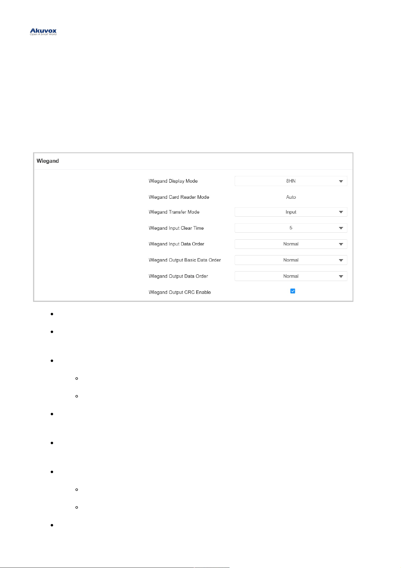
Integration via WiegandIntegration via Wiegand
A02 access control terminal can be integrated with the third-party devices via Wiegand.
To set it up, go to Device > WiegandDevice > Wiegand interface.
Wiegand Display ModeWiegand Display Mode: Select the Wiegand card code format from the provided options.
Wiegand Card Reader ModeWiegand Card Reader Mode: The transmission format should be identical between the
access control terminal and the third-party device. It is automatically configured.
Wiegand Transfer ModeWiegand Transfer Mode :
InputInput: A08 serves as a receiver.
OutputOutput: A08 serves as a sender.
Wiegand Input Clear TimeWiegand Input Clear Time: When the interval of entering passwords exceeds the time. All entered
passwords will be cleared.
Wiegand Input Data OrderWiegand Input Data Order: Set the Wiegand input data sequence between Normal and Reversed. If you
select Reversed, then the input card number will be reversed.
Wiegand Output Basic Data OrderWiegand Output Basic Data Order: Set the sequence of the Wiegand output data.
NormalNormal: The data is displayed as received.
ReversedReversed: The order of the data bits is reversed.
Wiegand Output Data Order:Wiegand Output Data Order: Determine the sequence of the card number.
Integration with Third Party DeviceIntegration with Third Party Device
NormalNormal: The card number is displayed as received.
ReversedReversed: The order of the card number is reversed.
Wiegand Output CRCWiegand Output CRC: It is enabled by default for Wiegand data inspection. Disabling it may lead to
integration failure with third-party devices.
Integration via HTTP APIIntegration via HTTP API
HTTP API is designed to achieve a network-based integration between the third-party device with the Akuvox intercom
device.
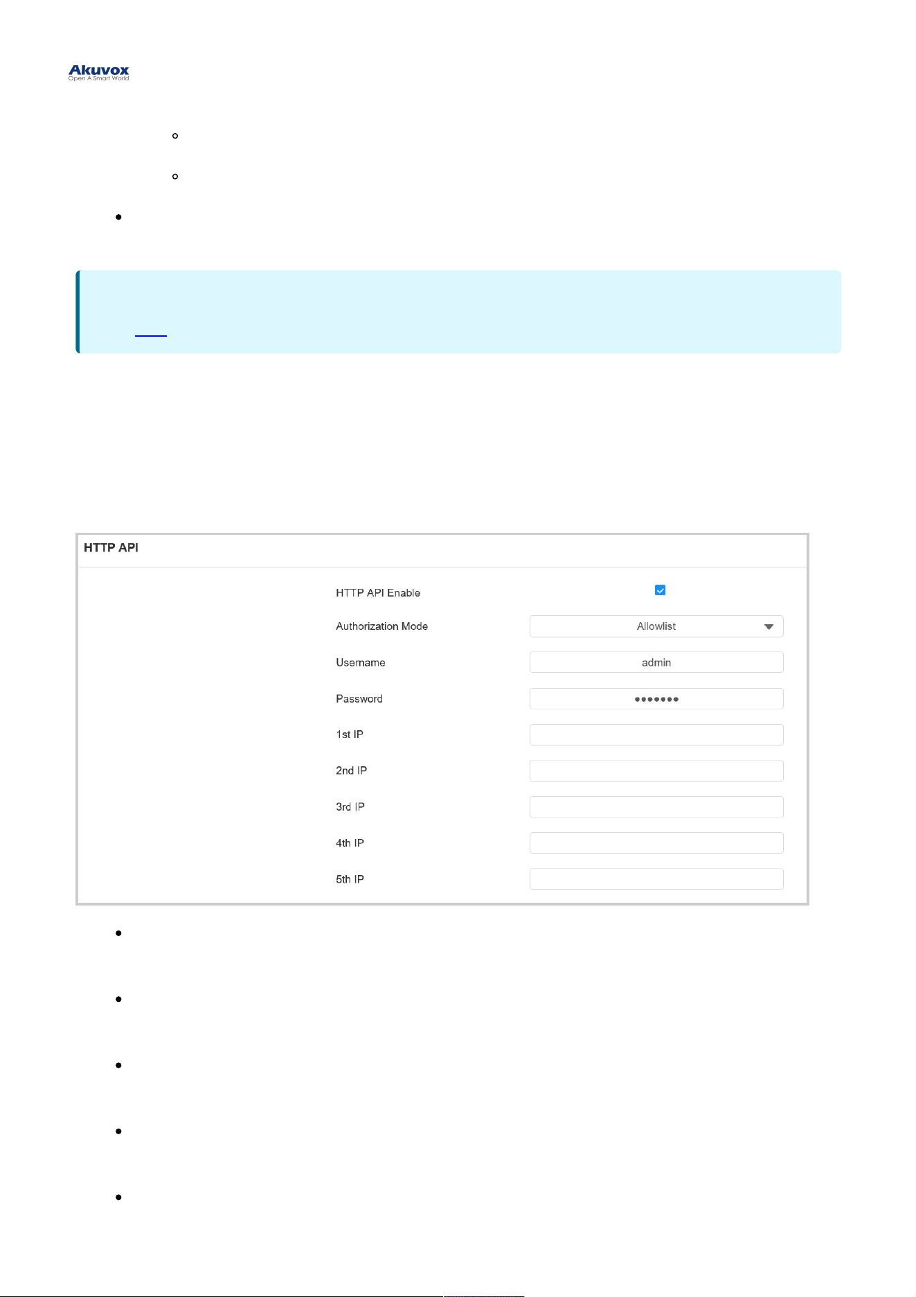
To set it up, go to Setting > HTTP APISetting > HTTP API interface.
EnabledEnabled: Enable or disable the HPTT API function for third-party integration. If the function is disabled, any
request to initiate the integration will be denied and return HTTP 403 forbidden status.
Authorization ModeAuthorization Mode: Select among the following options: None, Normal, Allowlist, Basic, Digest, and Token
for authorization type, which will be explained in detail in the following chart.
UsernameUsername: Enter the user name when BasicBasic or DigestDigest authorization mode is selected. The default
username is admin.
PasswordPassword: Enter the password when BasicBasic or DigestDigest authorization mode is selected. The default
password is admin.
1st IP-5th IP1st IP-5th IP: Enter the IP address of the third-party devices when the AllowlistAllowlist authorization is selected for
the integration.
NoteNote
Click herehere to see detailed configuration steps.
Please refer to the following description for the Authentication mode:Please refer to the following description for the Authentication mode:
NO.NO.
AuthorizationAuthorization
ModeMode
DescriptionDescription
1 None No authentication is required for HTTP API as it is only used for demo testing.
2 Normal This mode is used by Akuvox developers only.
3 Allowlist
If this mode is selected, you are only required to fill in the IP address of the third-party
device for the authentication. The allowlist is suitable for operation in the LAN.
4 Basic
If this mode is selected, you are required to fill in the username and password for the
authentication. In the Authorization field of the HTTP request header, use the Base64
encode method to encode of username and password.
5 Digest
The password encryption method only supports MD5. MD5( Message-Digest Algorithm)
In the Authorization field of HTTP request header: WWW-Authenticate: Digest
realm="HTTPAPI",qop="auth,auth-int",nonce="xx", opaque="xx".
6 Token This mode is used by Akuvox developers only.
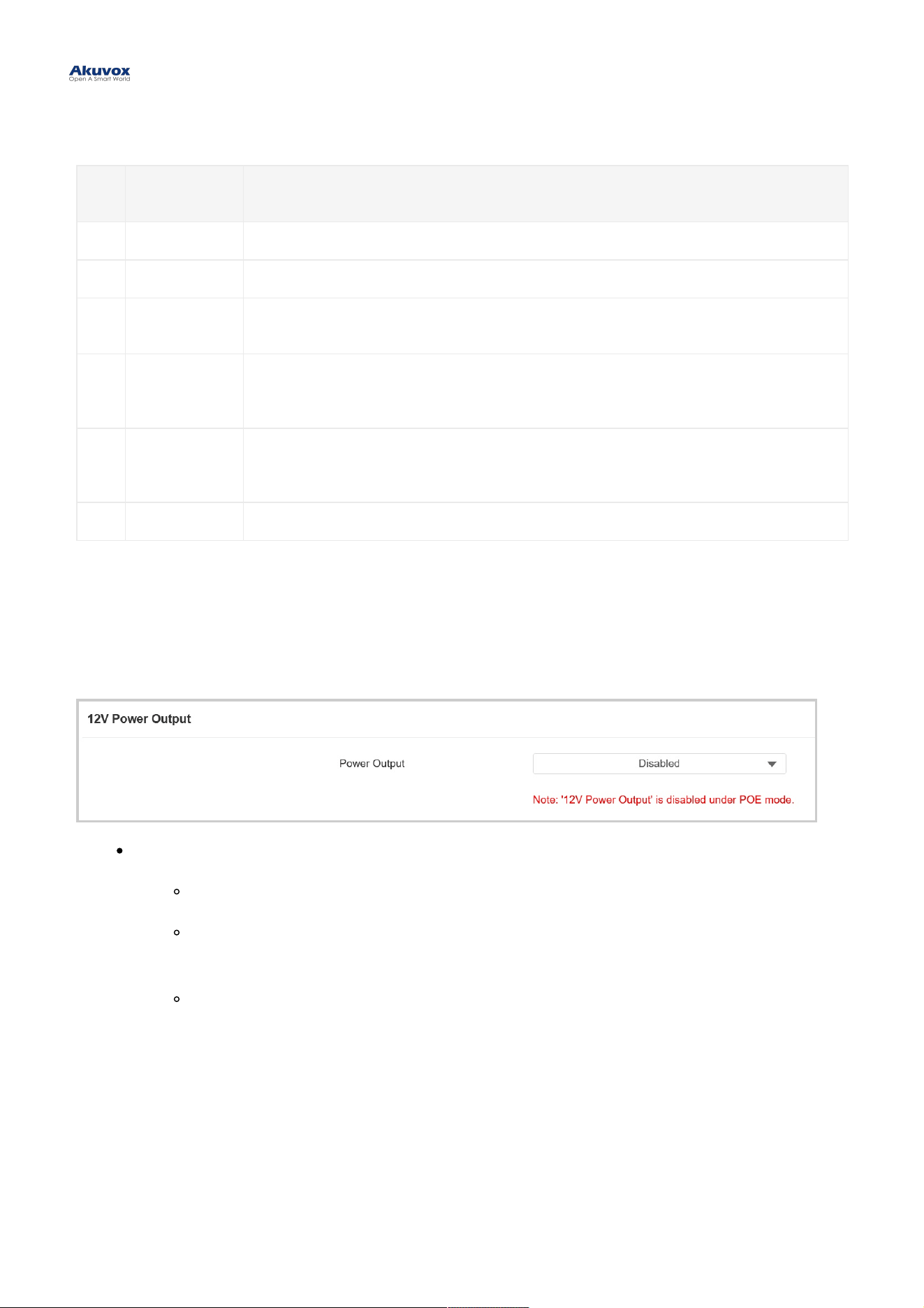
Power Output ControlPower Output Control
The door phone can serve as a power supply for the external relays.
To set it up, go to Access Control > RelayAccess Control > Relay interface.
Power OutputPower Output:
AlwaysAlways: The device can provide continuous power to the third-party device.
Triggered By Open RelayTriggered By Open Relay: The device can provide power to the third-party device via 12 output
and GND interface during the timeout when the status of relays is shifted from low to high.
Security Relay ASecurity Relay A : The device can work with the security relay.
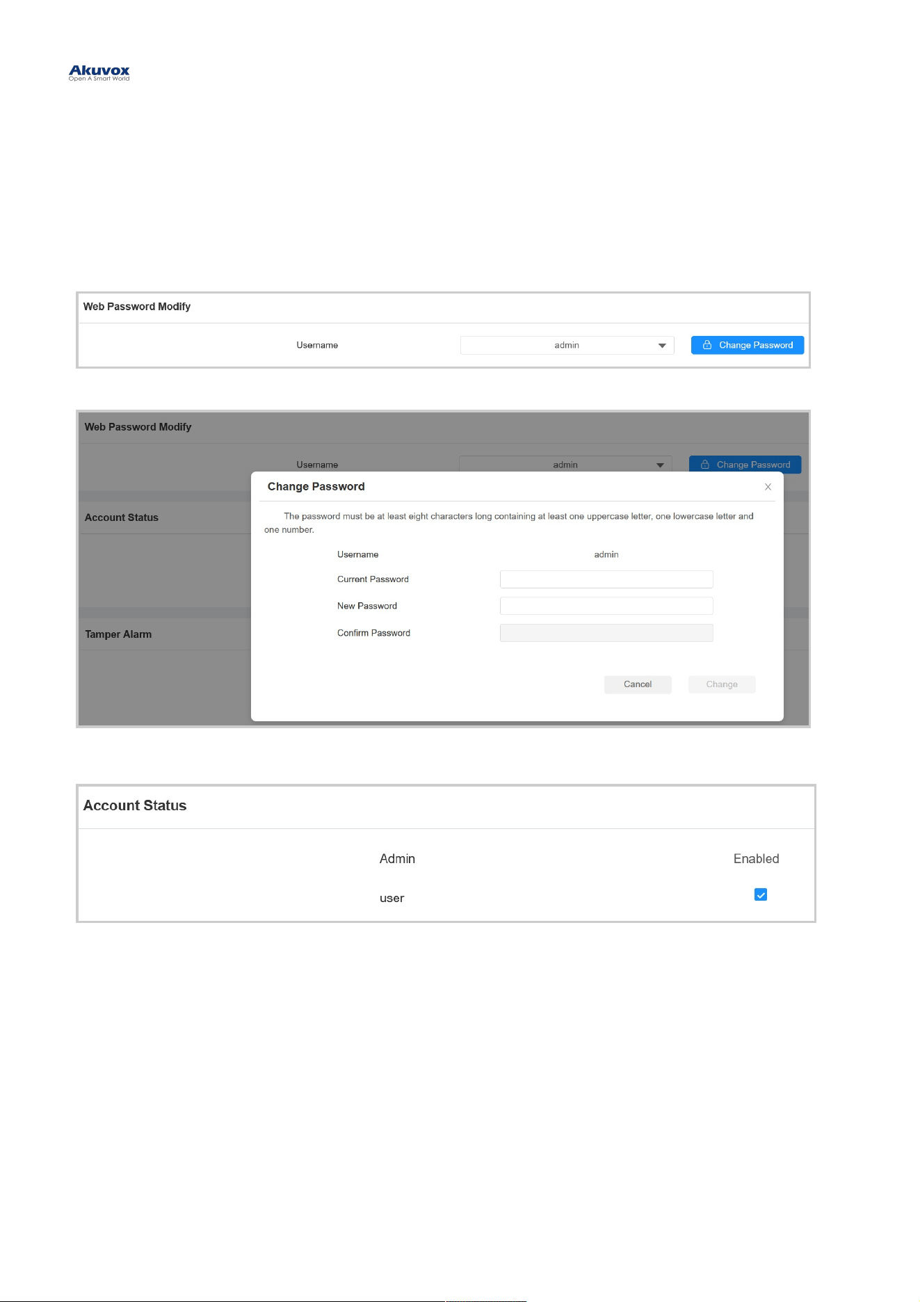
You can modify the device web password for both the administrator account and the user account.
To set it up, go to System > Security > Web Password ModifySystem > Security > Web Password Modify interface.
Click Change PasswordChange Password to modify the password.
To enable or disable the user account, scroll to the Account StatusAccount Status section.
Password ModificationPassword Modification
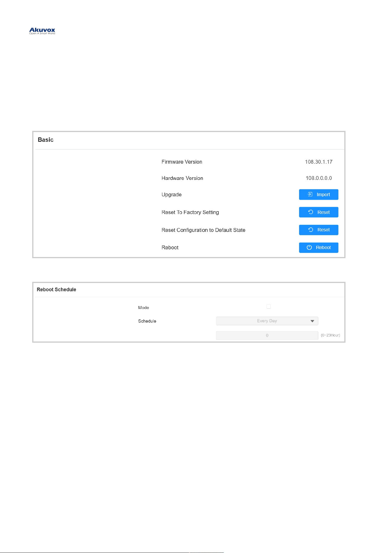
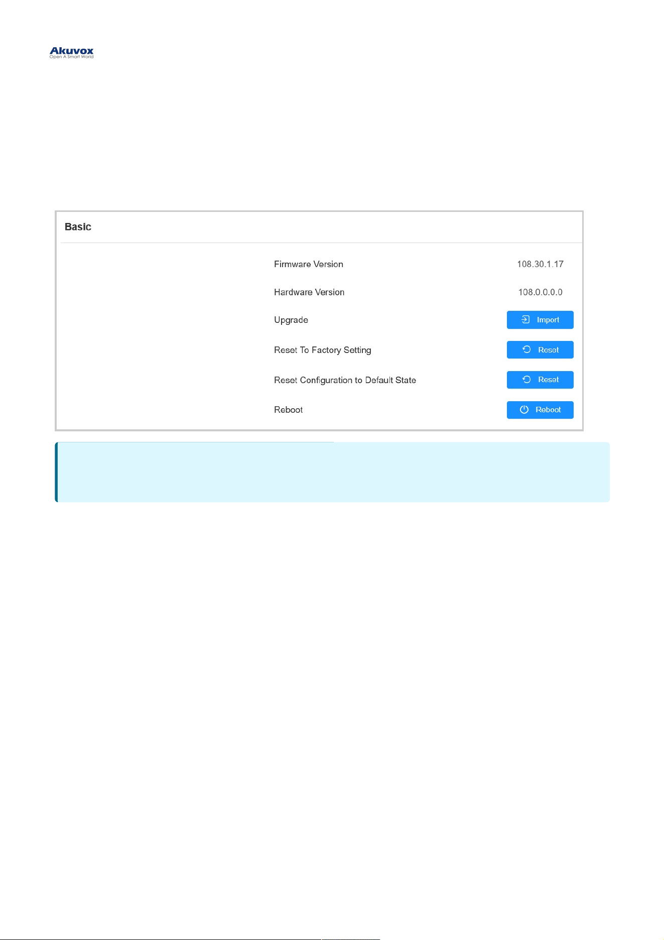
RebootReboot
Reboot the device on the web System > UpgradeSystem > Upgrade interface.
To set up the device restart schedule, go to System > Auto Provisioning > Reboot ScheduleSystem > Auto Provisioning > Reboot Schedule interface.
ResetReset
You can select Reset To Factory Setting Reset To Factory Setting if you want to reset the device (deleting both configuration data and user
data such as RF cards, face data, and so on). Or, select Reset Configuration to Default State (Except Data)Reset Configuration to Default State (Except Data)
ResetReset, if you want to reset the device (retaining the user data).
Reset the device on System > UpgradeSystem > Upgrade interface.
System Reboot and ResetSystem Reboot and Reset