
DS-K1T502 Series Access Control Terminal
User Manual

Legal Informaon
About this Document
●
This Document includes instrucons for using and managing the Product. Pictures, charts,
images and all other
informaon hereinaer are for descripon and explanaon only.
●
The
informaon contained in the Document is subject to change, without noce, due to
rmware updates or other reasons. Please nd the latest version of the Document at the
Hikvision website ( hps://www.hikvision.com ). Unless otherwise agreed, Hangzhou Hikvision
Digital Technology Co., Ltd. or its aliates (hereinaer referred to as "Hikvision") makes no
warranes, express or implied.
●
Please use the Document with the guidance and assistance of professionals trained in
supporng the Product.
About this Product
●
This product can only enjoy the aer-sales service support in the country or region where the
purchase is made.
●
If the product you choose is a video product, please scan the following QR code to obtain the
"Iniaves on the Use of Video Products", and read it carefully.
Acknowledgment of Intellectual Property Rights
●
Hikvision owns the copyrights and/or patents related to the technology embodied in the
Products described in this Document, which may include licenses obtained from third pares.
●
Any part of the Document, including text, pictures, graphics, etc., belongs to Hikvision. No part
of this Document may be excerpted, copied, translated, or modied in whole or in part by any
means without
wrien permission.
●
and other Hikvision's trademarks and logos are the properes of Hikvision in
various
jurisdicons.
●
Other trademarks and logos menoned are the properes of their respecve owners.
LEGAL DISCLAIMER
●
TO THE MAXIMUM EXTENT PERMITTED BY APPLICABLE LAW, THIS DOCUMENT AND THE
PRODUCT DESCRIBED, WITH ITS HARDWARE, SOFTWARE AND FIRMWARE, ARE PROVIDED "AS
IS" AND "WITH ALL FAULTS AND ERRORS". HIKVISION MAKES NO WARRANTIES, EXPRESS OR
DS-K1T502 Series Access Control Terminal User Manual
i

IMPLIED, INCLUDING WITHOUT LIMITATION, MERCHANTABILITY, SATISFACTORY QUALITY, OR
FITNESS FOR A PARTICULAR PURPOSE. THE USE OF THE PRODUCT BY YOU IS AT YOUR OWN RISK.
IN NO EVENT WILL HIKVISION BE LIABLE TO YOU FOR ANY SPECIAL, CONSEQUENTIAL,
INCIDENTAL, OR INDIRECT DAMAGES, INCLUDING, AMONG OTHERS, DAMAGES FOR LOSS OF
BUSINESS PROFITS, BUSINESS INTERRUPTION, OR LOSS OF DATA, CORRUPTION OF SYSTEMS, OR
LOSS OF DOCUMENTATION, WHETHER BASED ON BREACH OF CONTRACT, TORT (INCLUDING
NEGLIGENCE), PRODUCT LIABILITY, OR OTHERWISE, IN CONNECTION WITH THE USE OF THE
PRODUCT, EVEN IF HIKVISION HAS BEEN ADVISED OF THE POSSIBILITY OF SUCH DAMAGES OR
LOSS.
●
YOU ACKNOWLEDGE THAT THE NATURE OF THE INTERNET PROVIDES FOR INHERENT SECURITY
RISKS, AND HIKVISION SHALL NOT TAKE ANY RESPONSIBILITIES FOR ABNORMAL OPERATION,
PRIVACY LEAKAGE OR OTHER DAMAGES RESULTING FROM CYBER-ATTACK, HACKER ATTACK,
VIRUS INFECTION, OR OTHER INTERNET SECURITY RISKS; HOWEVER, HIKVISION WILL PROVIDE
TIMELY TECHNICAL SUPPORT IF REQUIRED.
●
YOU AGREE TO USE THIS PRODUCT IN COMPLIANCE WITH ALL APPLICABLE LAWS, AND YOU ARE
SOLELY RESPONSIBLE FOR ENSURING THAT YOUR USE CONFORMS TO THE APPLICABLE LAW.
ESPECIALLY, YOU ARE RESPONSIBLE, FOR USING THIS PRODUCT IN A MANNER THAT DOES NOT
INFRINGE ON THE RIGHTS OF THIRD PARTIES, INCLUDING WITHOUT LIMITATION, RIGHTS OF
PUBLICITY, INTELLECTUAL PROPERTY RIGHTS, OR DATA PROTECTION AND OTHER PRIVACY
RIGHTS. YOU SHALL NOT USE THIS PRODUCT FOR ANY PROHIBITED END-USES, INCLUDING THE
DEVELOPMENT OR PRODUCTION OF WEAPONS OF MASS DESTRUCTION, THE DEVELOPMENT OR
PRODUCTION OF CHEMICAL OR BIOLOGICAL WEAPONS, ANY ACTIVITIES IN THE CONTEXT
RELATED TO ANY NUCLEAR EXPLOSIVE OR UNSAFE NUCLEAR FUEL-CYCLE, OR IN SUPPORT OF
HUMAN RIGHTS ABUSES.
●
IN THE EVENT OF ANY CONFLICTS BETWEEN THIS DOCUMENT AND THE APPLICABLE LAW, THE
LATTER PREVAILS.
Data
Protecon
●
To protect data, the development of Hikvision Products incorporates privacy by design
principles. For example, for Products with facial
recognion features, biometrics data is stored in
your Products with encrypon method; for ngerprint Products, only ngerprint template will be
saved, which is impossible to reconstruct a
ngerprint image.
●
As a data controller/processor, you may process personal data, including collecon, storage, use,
processing, disclosure,
deleon, etc. You are advised to pay aenon to and comply with
applicable laws and regulaons related to the protecon of personal data, including without
limitaon, conducng security controls to safeguard personal data, such as, implemenng
reasonable administrave and physical security controls, conduct periodic reviews and the
assessments of the
eecveness of your security controls.
© Hangzhou Hikvision Digital Technology Co., Ltd. All rights reserved.
DS-K1T502 Series Access Control Terminal User Manual
ii
Symbol Convenons
The symbols that may be found in this document are dened as follows.
Symbol Descripon
Danger
Indicates a hazardous situaon which, if not avoided, will or could
result in death or serious injury.
Cauon
Indicates a potenally hazardous situaon which, if not avoided, could
result in equipment damage, data loss, performance degradaon, or
unexpected results.
Note
Provides addional informaon to emphasize or supplement
important points of the main text.
DS-K1T502 Series Access Control Terminal User Manual
iii

Regulatory Informaon
FCC Informaon
Please take aenon that changes or modicaon not expressly approved by the party responsible
for compliance could void the user’s authority to operate the equipment.
FCC compliance: This equipment has been tested and found to comply with the limits for a Class B
digital device, pursuant to part 15 of the FCC Rules. These limits are designed to provide
reasonable
protecon against harmful interference in a residenal installaon. This equipment
generates, uses and can radiate radio frequency energy and, if not installed and used in accordance
with the
instrucons, may cause harmful interference to radio communicaons. However, there is
no guarantee that interference will not occur in a parcular installaon. If this equipment does
cause harmful interference to radio or television
recepon, which can be determined by turning
the equipment o and on, the user is encouraged to try to correct the interference by one or more
of the following measures:
—Reorient or relocate the receiving antenna.
—Increase the
separaon between the equipment and receiver.
—Connect the equipment into an outlet on a circuit
dierent from that to which the receiver is
connected.
—Consult the dealer or an experienced radio/TV technician for help
This equipment should be installed and operated with a minimum distance 20cm between the
radiator and your body.
FCC
Condions
This device complies with part 15 of the FCC Rules. Operaon is subject to the following two
condions:
1. This device may not cause harmful interference.
2. This device must accept any interference received, including interference that may cause
undesired
operaon.
DS-K1T502 Series Access Control Terminal User Manual
iv
EU Conformity Statement
This product and - if applicable - the supplied accessories too are marked with "CE"
and comply therefore with the applicable harmonized European standards listed
under the EMC Direcve 2014/30/EU, the RoHS Direcve 2011/65/EU
2012/19/EU (WEEE direcve): Products marked with this symbol cannot be disposed
of as unsorted municipal waste in the European Union. For proper recycling, return
this product to your local supplier upon the purchase of equivalent new equipment,
or dispose of it at designated
collecon points. For more informaon see:
www.recyclethis.info
2006/66/EC (baery direcve): This product contains a baery that cannot be
disposed of as unsorted municipal waste in the European Union. See the product
documentaon for specic baery informaon. The baery is marked with this
symbol, which may include
leering to indicate cadmium (Cd), lead (Pb), or mercury
(Hg). For proper recycling, return the
baery to your supplier or to a designated
collecon point. For more informaon see:www.recyclethis.info
Industry Canada ICES-003 Compliance
This device meets the CAN ICES-3 (B)/NMB-3(B) standards requirements.
This device complies with Industry Canada licence-exempt RSS standard(s).
Operaon is subject to
the following two condions:
1. this device may not cause interference, and
2. this device must accept any interference, including interference that may cause undesired
operaon of the device.
Le présent appareil est conforme aux CNR d'Industrie Canada applicables aux appareils
radioexempts de licence.
L'exploitaon est autorisée aux deux condions suivantes :
1. l'appareil ne doit pas produire de brouillage, et
2.
l'ulisateur de l'appareil doit accepter tout brouillage radioélectrique subi, même si le brouillage
est
suscepble d'en compromere le fonconnement.
Under Industry Canada regulaons, this radio transmier may only operate using an antenna of a
type and maximum (or lesser) gain approved for the
transmier by Industry Canada. To reduce
potenal radio interference to other users, the antenna type and its gain should be so chosen that
the equivalent isotropically radiated power (e.i.r.p.) is not more than that necessary for successful
communicaon.
Conformément à la réglementaon d'Industrie Canada, le présent émeeur radio peut fonconner
avec une antenne d'un type et d'un gain maximal (ou inférieur) approuvé pour l'émeeur par
Industrie Canada. Dans le but de réduire les risques de brouillage radioélectrique à l'intenon des
autres
ulisateurs, il faut choisir le type d'antenne et son gain de sorte que la puissance isotrope
DS-K1T502 Series Access Control Terminal User Manual
v

rayonnée équivalente (p.i.r.e.) ne dépasse pas l'intensité nécessaire à l'établissement d'une
communicaon sasfaisante.
This equipment should be installed and operated with a minimum distance 20cm between the
radiator and your body.
Cet équipement doit être installé et ulisé à une distance minimale de 20 cm entre le radiateur et
votre corps.
DS-K1T502 Series Access Control Terminal User Manual
vi
Safety Instrucon
These instrucons are intended to ensure that user can use the product correctly to avoid danger
or property loss.
The
precauon measure is divided into Dangers and Cauons:
Dangers: Neglecng any of the warnings may cause serious injury or death.
Cauons: Neglecng any of the cauons may cause injury or equipment damage.
Dangers: Follow these safeguards to prevent
serious injury or death.
Cauons: Follow these precauons to prevent
potenal injury or material damage.
Dangers
●
All the electronic operaon should be strictly compliance with the electrical safety regulaons,
re prevenon regulaons and other related regulaons in your local region.
●
Please use the power adapter, which is provided by normal company. The power consumpon
cannot be less than the required value.
●
Do not connect several devices to one power adapter as adapter overload may cause over-heat
or
re hazard.
●
Please make sure that the power has been disconnected before you wire, install or dismantle the
device.
●
When the product is installed on wall or ceiling, the device shall be
rmly xed.
●
If smoke, odors or noise rise from the device, turn
o the power at once and unplug the power
cable, and then please contact the service center.
●
Do not ingest baery, Chemical Burn Hazard.
This product contains a
coin/buon cell baery. If the coin/buon cell baery is swallowed, it
can cause severe internal burns in just 2 hours and can lead to death.
Keep new and used
baeries away from children. If the baery compartment does not close
securely, stop using the product and keep it away from children. If you think baeries might have
been swallowed or placed inside any part of the body, seek immediate medical
aenon.
●
If the product does not work properly, please contact your dealer or the nearest service center.
Never
aempt to disassemble the device yourself. (We shall not assume any responsibility for
problems caused by unauthorized repair or maintenance.)
Cauons
●
This equipment is not suitable for use in locaons where children are likely to be present.
●
Do not drop the device or subject it to physical shock, and do not expose it to high
electromagnesm radiaon. Avoid the equipment installaon on vibraons surface or places
subject to shock (ignorance can cause equipment damage).
DS-K1T502 Series Access Control Terminal User Manual
vii

●
Do not place the device in extremely hot (refer to the specicaon of the device for the detailed
operang temperature), cold, dusty or damp locaons, and do not expose it to high
electromagnec radiaon.
●
The device cover for indoor use shall be kept from rain and moisture.
●
Exposing the equipment to direct sun light, low venlaon or heat source such as heater or
radiator is forbidden (ignorance can cause
re danger).
●
Do not aim the device at the sun or extra bright places. A blooming or smear may occur
otherwise (which is not a
malfuncon however), and aecng the endurance of sensor at the
same
me.
●
Please use the provided glove when open up the device cover, avoid direct contact with the
device cover, because the acidic sweat of the ngers may erode the surface coang of the device
cover.
●
Please use a
so and dry cloth when clean inside and outside surfaces of the device cover, do
not use alkaline detergents.
●
Please keep all wrappers aer unpack them for future use. In case of any failure occurred, you
need to return the device to the factory with the original wrapper.
Transportaon without the
original wrapper may result in damage on the device and lead to addional costs.
●
Improper use or replacement of the
baery may result in hazard of explosion. Replace with the
same or equivalent type only. Dispose of used baeries according to the instrucons provided by
the
baery manufacturer.
●
You can view the device License via the website: hp://opensource.hikvision.com/Home/List?
id=46
.
DS-K1T502 Series Access Control Terminal User Manual
viii
Available Models
The access control terminal contains the following models:
Product Name Model Wireless
Access Control Terminal DS-K1T502DBWX-C 13.56 MHz Card Presenng
Frequency, Wi-Fi,
2.4G,Bluetooth
DS-K1T502DBFWX-C 13.56 MHz Card Presenng
Frequency, Wi-Fi,
2.4G,Bluetooth
DS-K1T502DBFWX 13.56 MHz Card Presenng
Frequency, Wi-Fi,
2.4G,Bluetooth
DS-K1T502DBWX 13.56 MHz Card Presenng
Frequency, Wi-Fi,
2.4G,Bluetooth
Table 1-1 Available Mobile Web Browsers
Operaon System Browser Version Available
Android Xiaomi 12, default
browser
16.6.6 Yes
Huawei P30, default
browser
12.1.1.321 Yes
Xiaomi 5s plus, default
browser
14.2.22 Yes
Huawei P30 Pro,
default browser
12.1.2.301 Yes
Redmi k40, default
browser
16.5.12 Yes
IOS Safari 15.4 Yes
DS-K1T502 Series Access Control Terminal User Manual
ix

Contents
Chapter 1 Overview .................................................................................................................... 1
1.1 Overview ................................................................................................................................ 1
1.2 Features ................................................................................................................................. 1
1.3 Appearance Descripon ......................................................................................................... 1
Chapter 2 Installaon ................................................................................................................. 4
2.1 Installaon Environment ........................................................................................................ 4
2.2 Install without Gang Box ........................................................................................................ 4
Chapter 3 Device Wiring ............................................................................................................. 8
3.1 Terminal
Descripon .............................................................................................................. 8
3.2 External Device Wiring ........................................................................................................... 9
3.3 Wire Secure Door Control Unit ............................................................................................ 10
Chapter 4
Acvaon ................................................................................................................. 12
4.1 Acvate via Mobile Web ...................................................................................................... 12
4.2 Acvate via Web Browser .................................................................................................... 13
4.3
Acvate via SADP ................................................................................................................. 13
4.4 Acvate Device via iVMS-4200 Client Soware ................................................................... 14
Chapter 5 Identy Authencaon ............................................................................................ 16
5.1
Authencate via Single Credenal ....................................................................................... 16
5.2 Authencate via Mulple Credenal ................................................................................... 16
Chapter 6 Call and Video Intercom ............................................................................................ 18
Chapter 7
Operaon via Web Browser ...................................................................................... 19
7.1 Login .................................................................................................................................... 19
7.2 Forget Password ................................................................................................................... 19
7.3 Download Web Plug-In ........................................................................................................ 19
7.4 Help ...................................................................................................................................... 20
7.4.1 Open Source
Soware Licenses .................................................................................. 20
DS-K1T502 Series Access Control Terminal User Manual
x

7.4.2 View Online Help Document ....................................................................................... 20
7.5 Logout .................................................................................................................................. 20
7.6 Quick
Operaon via Web Browser ....................................................................................... 20
7.6.1 Set Security Queson .................................................................................................. 20
7.6.2 Select Language .......................................................................................................... 20
7.6.3 Time Sengs ............................................................................................................... 21
7.6.4 Privacy Sengs ........................................................................................................... 21
7.6.5 No. and System Network ............................................................................................ 22
7.7 Person Management ............................................................................................................ 23
7.8 Access Control Management ............................................................................................... 24
7.8.1 Overview ..................................................................................................................... 24
7.8.2 Search Event ................................................................................................................ 26
7.8.3 Door Parameter
Conguraon .................................................................................... 27
7.8.4
Authencaon Sengs ............................................................................................... 30
7.8.5 Card Sengs ............................................................................................................... 34
7.8.6 Linkage Sengs .......................................................................................................... 36
7.8.7 Set Working Mode via PC Web ................................................................................... 37
7.8.8 Set Remote
Vericaon .............................................................................................. 38
7.8.9 Privacy Sengs ........................................................................................................... 39
7.9 Video Intercom
Sengs ....................................................................................................... 41
7.9.1 Device Management ................................................................................................... 41
7.9.2 Set Device No. via Web ............................................................................................... 41
7.9.3
Congure Video Intercom Network Parameters via Web Browser ............................. 43
7.9.4 Call Sengs ................................................................................................................. 43
7.9.5 Set Press Buon to Call via PC Web ............................................................................ 44
7.9.6 Number
Sengs via PC Web ...................................................................................... 44
7.10 System Conguraon ......................................................................................................... 45
7.10.1 Set Local Parameters ................................................................................................. 45
DS-K1T502 Series Access Control Terminal User Manual
xi

7.10.2 View Device Informaon via PC Web ........................................................................ 45
7.10.3 Set Time .................................................................................................................... 45
7.10.4 Set DST ...................................................................................................................... 46
7.10.5 Change Administrator's Password ............................................................................. 47
7.10.6 Account Security
Sengs via PC Web ....................................................................... 47
7.10.7 Online Users .............................................................................................................. 47
7.10.8 View Device Arming/Disarming Informaon via PC Web ......................................... 47
7.10.9 Network Sengs ....................................................................................................... 48
7.10.10 Set Video and Audio Parameters via PC Web ......................................................... 54
7.10.11 Image Parameters Sengs ...................................................................................... 55
7.10.12 Set Event Detecon via PC Web .............................................................................. 57
7.10.13 Alarm Sengs via PC Web ...................................................................................... 58
7.10.14 Access
Conguraon ............................................................................................... 58
7.11 System and Maintenance ................................................................................................... 61
7.11.1 Reboot ...................................................................................................................... 61
7.11.2 Upgrade .................................................................................................................... 61
7.11.3
Restoraon ................................................................................................................ 61
7.11.4 Export Device Parameters via PC Web ...................................................................... 62
7.11.5 Import Device Parameters via PC Web ..................................................................... 62
7.11.6 Device Debugging ..................................................................................................... 62
7.11.7 View Log via PC Web ................................................................................................. 63
7.11.8 Security Mode
Sengs ............................................................................................. 63
7.11.9
Cercate Management ........................................................................................... 64
Chapter 8 Congure the Device via the Mobile Browser ........................................................... 66
8.1 Login .................................................................................................................................... 66
8.2 Forget Password ................................................................................................................... 66
8.3 Account Security
Sengs ..................................................................................................... 67
8.4 Home ................................................................................................................................... 67
DS-K1T502 Series Access Control Terminal User Manual
xii

8.5 Conguraon ....................................................................................................................... 68
8.5.1 View Device Informaon ............................................................................................. 68
8.5.2 Time
Sengs ............................................................................................................... 68
8.5.3 Set DST ........................................................................................................................ 69
8.5.4 User Management ...................................................................................................... 69
8.5.5 Network ...................................................................................................................... 70
8.5.6 User Management ...................................................................................................... 72
8.5.7 Event Search ................................................................................................................ 74
8.5.8 Audio Sengs ............................................................................................................. 75
8.5.9 Access Control Sengs ............................................................................................... 75
8.5.10 Call Sengs ............................................................................................................... 82
8.5.11 Set Privacy Parameters via Mobile Web ................................................................... 85
8.5.12 Password Mode ........................................................................................................ 85
8.5.13 Upgrade and Maintenance ....................................................................................... 85
8.5.14 View User Document ................................................................................................ 86
8.5.15 Open Source Soware Licenses ................................................................................ 86
8.5.16 Log Out of Mobile Web ............................................................................................. 87
Chapter 9 Other
Plaorms to Congure .................................................................................... 88
Appendix A. Tips for Scanning Fingerprint ................................................................................ 89
Appendix B. Dimension ............................................................................................................ 91
DS-K1T502 Series Access Control Terminal User Manual
xiii

Chapter 1 Overview
1.1 Overview
Access control terminal is a kind of access control terminal for authencaon. It supports two-way
audio, remote live view, picture capture, video recording through NVR, and so on.
1.2 Features
●
Manage access control, video intercoms, and video security with one device
●
IP65 & IK09 protecons, as well as increased stability with zinc alloy materials
●
Mulple authencaon methods, including ngerprint, card, etc.
Note
Fingerprint funcon is supported by parts of the device modules.
●
Remote control via the Hik-Connect mobile app
●
Connects to external access controller via Wiegand protocol
●
Two-way audio via SIP 2.0 protocol
●
RS-485
communicaon for connecng external card reader
●
Supports network
connecon via AP
●
Supports H.265 video encoding format
1.3 Appearance
Descripon
View the device appearance descripon.
DS-K1T502 Series Access Control Terminal User Manual
1
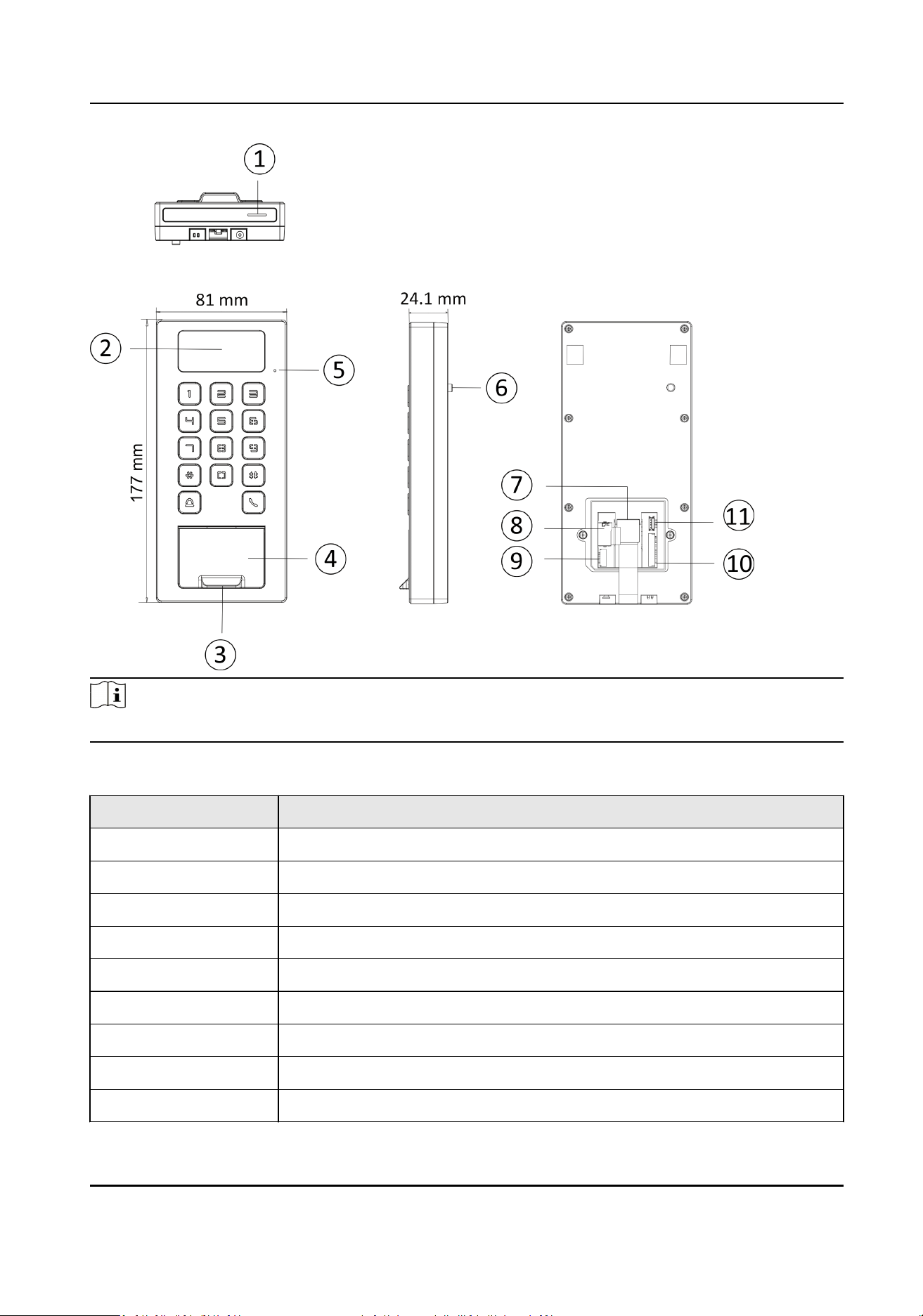
Note
The pictures here are for reference only.
Table 1-1 Appearance Descripon
No. Descripon
1 Loudspeaker
2 Camera (Supported by parts of Device Models)
3 Fingerprint Module (Supported by parts of Device Models)
4 Card Presenng Area
5 MIC
6 Tamper
7 Network Interface
8 SD Card Slot
9 Wiring Terminal for Alarm Input/ Output
DS-K1T502 Series Access Control Terminal User Manual
2

No. Descripon
10 Wiring Terminal
11 Debugging Port (For debugging only)
DS-K1T502 Series Access Control Terminal User Manual
3
Chapter 2 Installaon
2.1 Installaon Environment
●
Install the device at least 2 meters away from the light, and at least 3 meters away from the
window or the door.
●
Make sure the environment
illuminaon is more than 100 Lux.
Note
For details about installaon environment, see Tips for Installaon Environment.
2.2 Install without Gang Box
Steps
Note
The addional force shall be equal to three mes the weight of the equipment. The equipment ad
its associated mounng means shall remain secure during the installaon. Aer the installaon,
the equipment, including any associated mounng plate, shall not be damaged.
1.
Secure the mounng plate on the wall with 4 supplied screws (SC-KA4X25-SUS).
DS-K1T502 Series Access Control Terminal User Manual
4
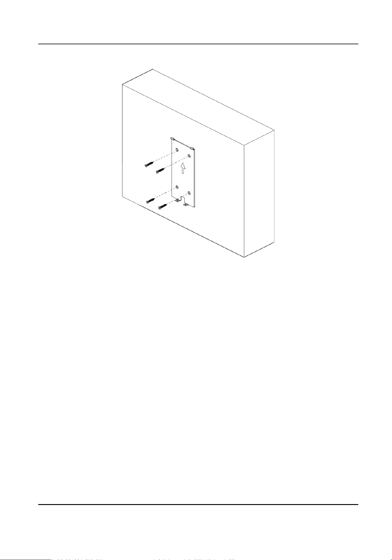
Figure 2-1 Secure Mounng Plate
2.
Route the cable through the cable hole of the mounng plate, and connect to corresponding
external devices' cables.
3.
Apply Silicone sealant among the joints between the device rear panel and the wall (except the
lower side) to keep the raindrop from entering.
DS-K1T502 Series Access Control Terminal User Manual
5
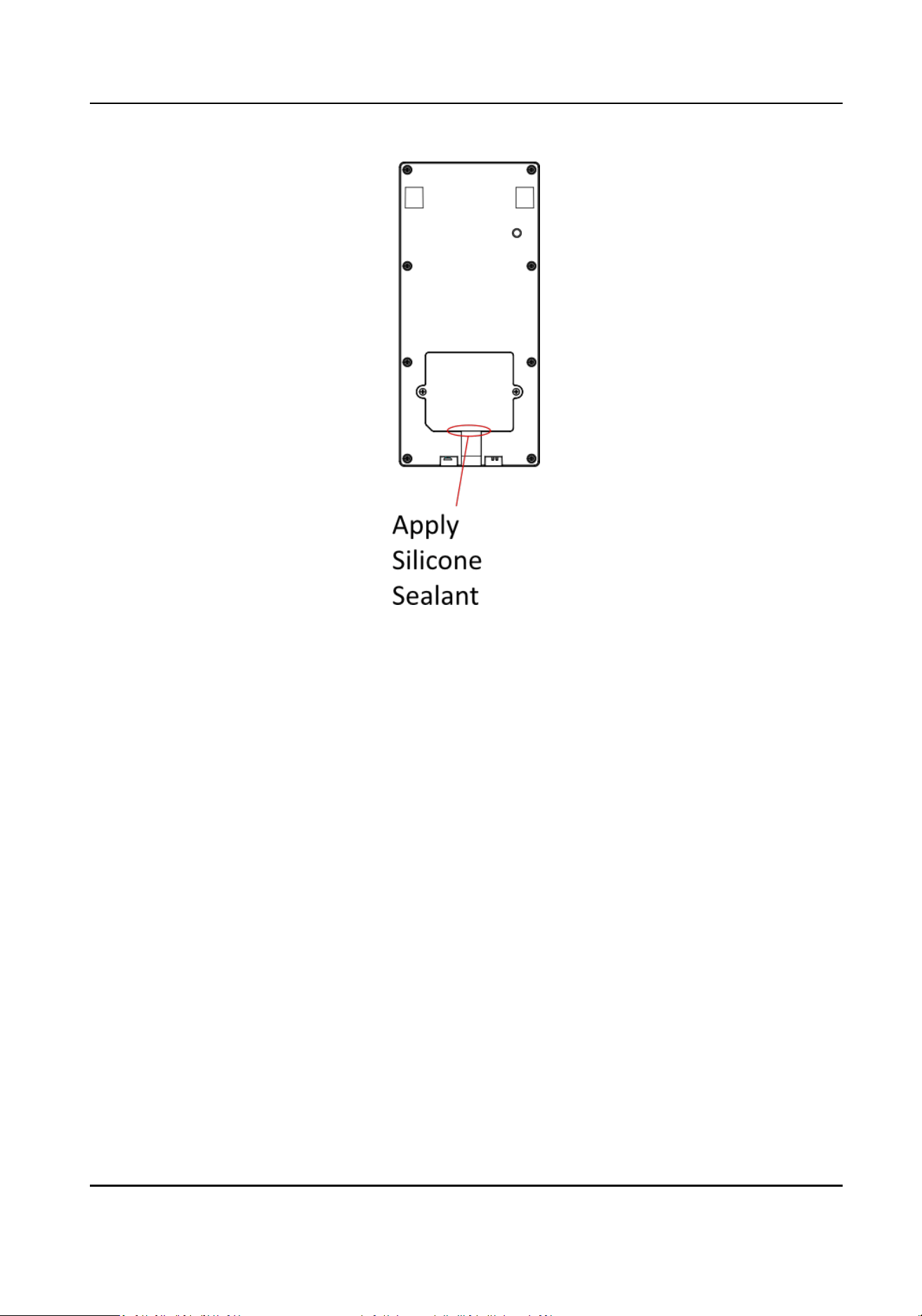
Figure 2-2 Apply Silicone Sealant on the Side
4.
Align the device with the mounng plate, and secure the device on the mounng plate with 1
supplied screw (SC-KM3X6-T10-SUS).
DS-K1T502 Series Access Control Terminal User Manual
6
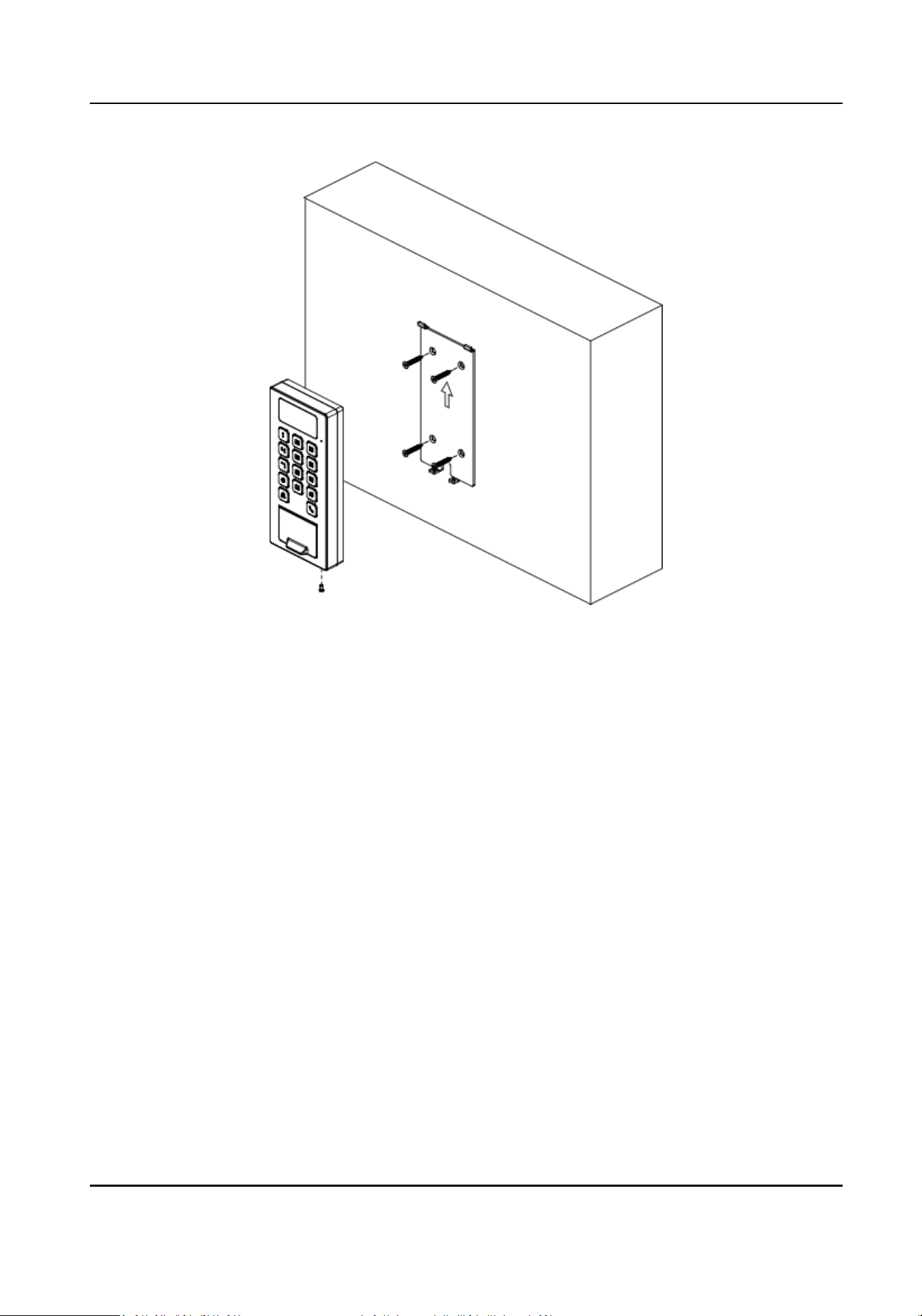
Figure 2-3 Secure Device
DS-K1T502 Series Access Control Terminal User Manual
7
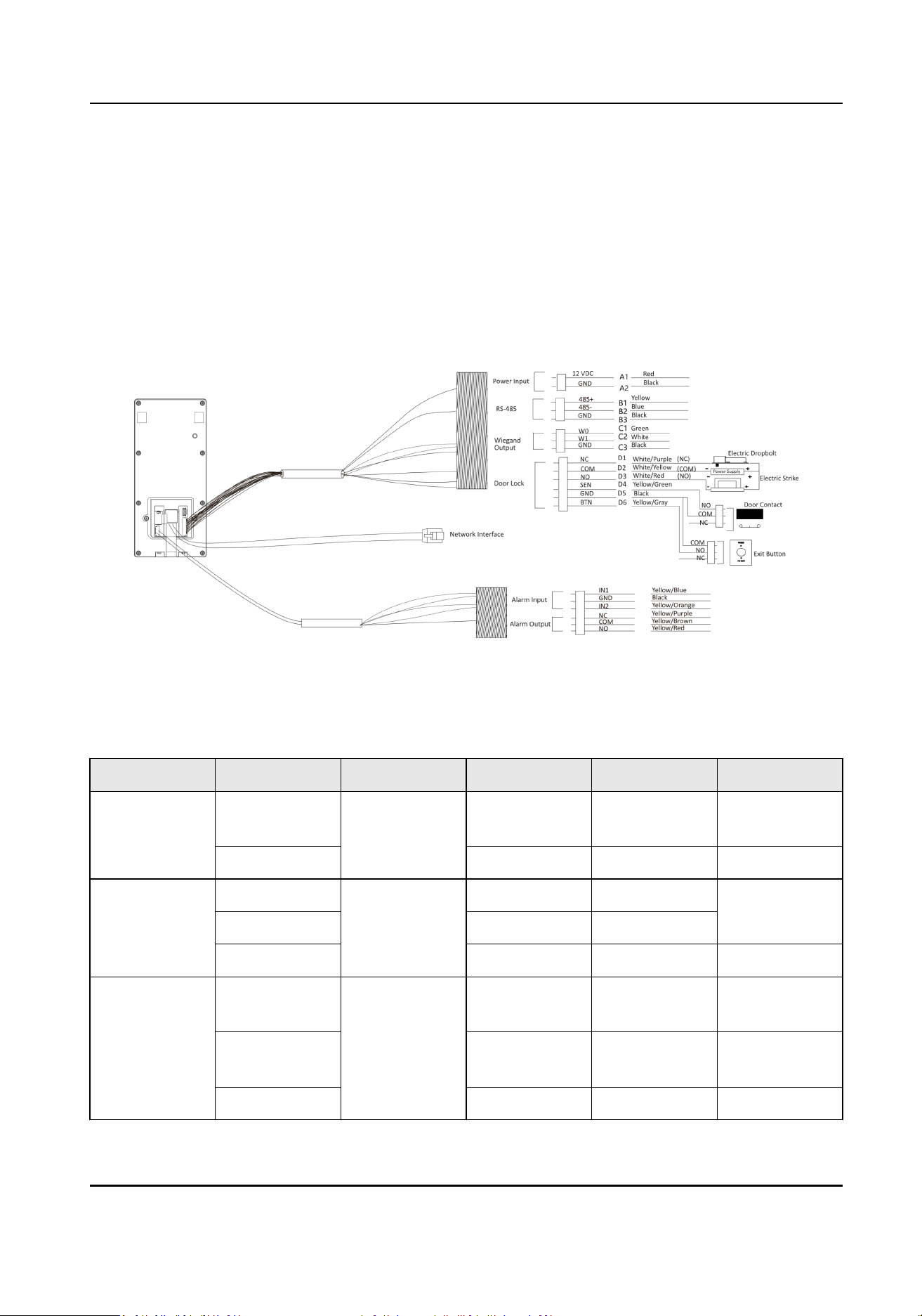
Chapter 3 Device Wiring
3.1 Terminal Descripon
The terminals contains power input, alarm input, alarm output, RS-485, Wiegand output, and door
lock.
The terminal's diagram is as follows:
Figure 3-1 Terminal Diagram
The descripons of the terminals are as follows:
Table 3-1 Terminal
Descripons
Group No. Funcon Color Name Descripon
Group A A1 Power Input Red +12 V 12 VDC Power
Supply
A2 Black GND Ground
Group B B1 RS-485 Yellow 485+ RS-485 Wiring
B2 Blue 485-
B3 Black GND Ground
Group C C1 Wiegand Green W0 Wiegand
Wiring 0
C2 White W1 Wiegand
Wiring 1
C3 Black GND Ground
DS-K1T502 Series Access Control Terminal User Manual
8

Group No. Funcon Color Name Descripon
Group D D1 Door Lock White/Purple NC Lock Wiring
(NC)
D2 White/Yellow COM Common
D3 White/Red NO Lock Wiring
(NO)
D4 Yellow/Green SENSOR Door Contact
D5 Black GND Ground
D6 Yellow/Gray BTN Exit Door
Wiring
3.2 External Device Wiring
Wire the external device.
The wiring diagram is as follows.
DS-K1T502 Series Access Control Terminal User Manual
9
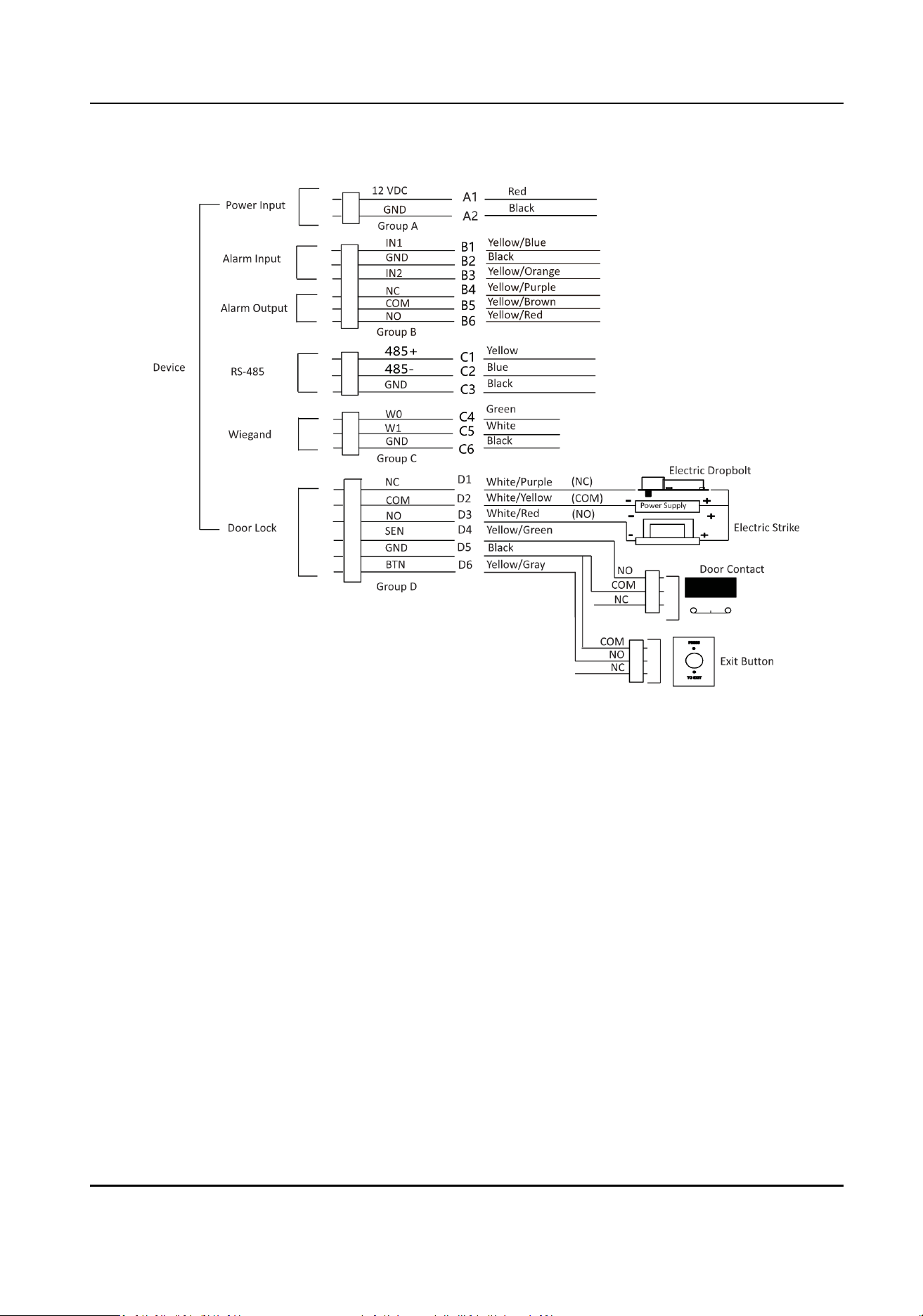
Figure 3-2 External Device Wiring
3.3 Wire Secure Door Control Unit
You can connect the terminal with the secure door control unit.
The wiring diagram is as follows.
DS-K1T502 Series Access Control Terminal User Manual
10
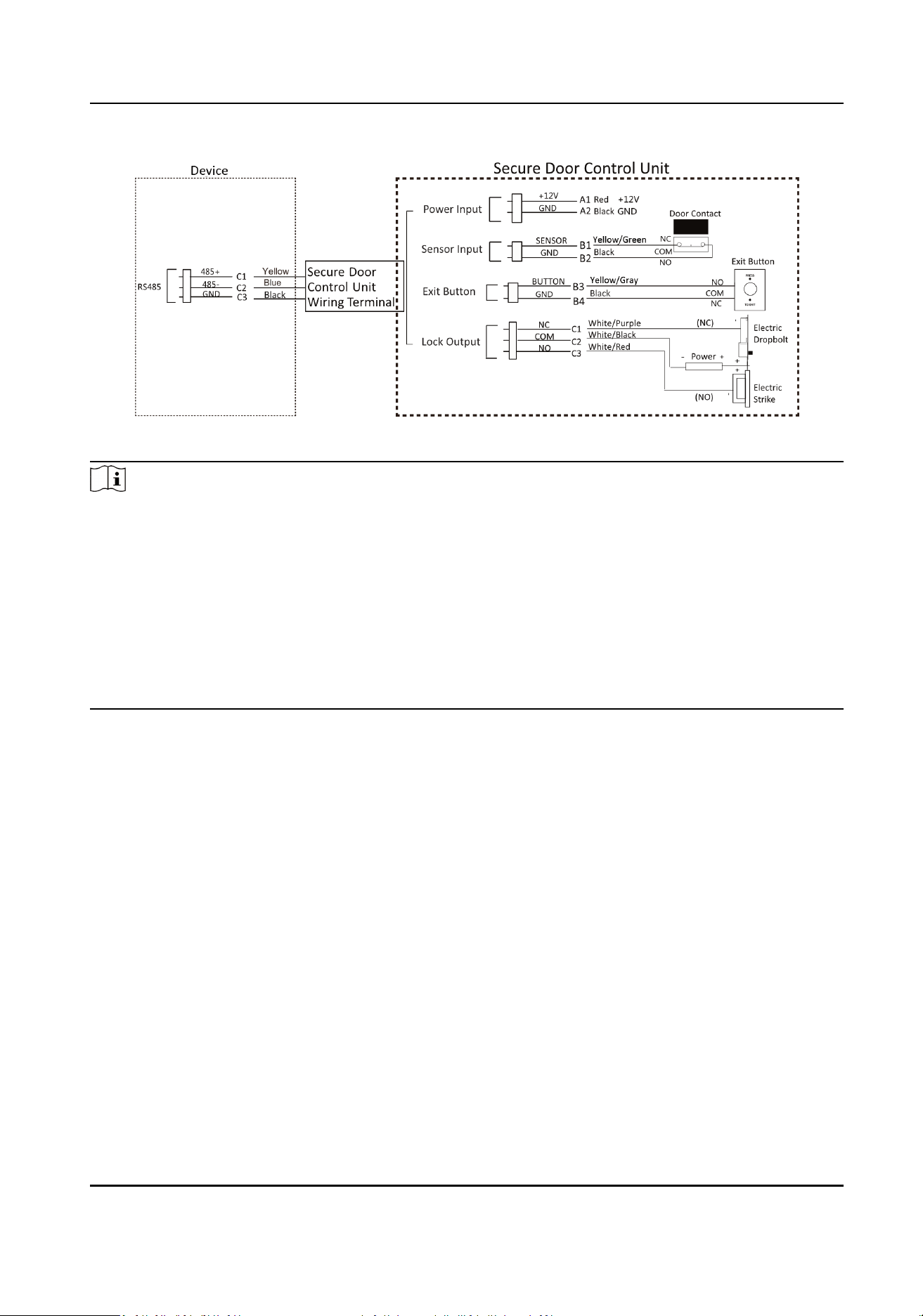
Figure 3-3 Secure Door Control Unit Wiring
Note
●
The secure door control unit should connect to an external power supply separately. The
suggested external power supply is 12V, 0.5A.
●
For scenarios with high safety requirement, use the secure door control unit wiring rst.
●
You can ask the technical support to purchase for the secure door control unit separately.
●
The picture here are parts of the wiring. For details, see the secure door control unit's user
manual.
●
The device supports to connect a secure door control unit with binding funcon. A secure door
control unit that has been bound to another device must be unbound before bounding a new
device.
DS-K1T502 Series Access Control Terminal User Manual
11
Chapter 4 Acvaon
You should acvate the device before the rst login. Aer powering on the device, the system will
switch to Device
Acvaon page.
Acvaon via the device, SADP tool and the client soware are supported.
The default values of the device are as follows:
●
The default IP address: 192.0.0.64
●
The default port No.: 80
●
The default user name: admin
4.1
Acvate via Mobile Web
You can acvate the device via mobile web.
Steps
Note
Aer powering on the device for the rst me, the hotspot funcon is enabled by default.
1.
Enable the mobile phone's Wi-Fi funcon. Search and add the device hotspot (hotspot name:
AP_Serial No.).
Note
●
Hotspot name/password: AP_Serial No.
●
Hold key 5 on the device keypad for 5 s to enable/disable the hotspot funcon.
●
Aer 30 min aer device powering on, the hotspot funcon will be disabled automacally.
●
Aer device acvaon, the hotspot password will be changed to the device acvaon
password.
2.
The mobile phone will jump to the web browser page. Create a new password (admin password)
and
conrm the password.
Note
Characters containing admin and nimda are not supported to be set as acvaon password.
Cauon
STRONG PASSWORD RECOMMENDED-We highly recommend you create a strong password of
your own choosing (using a minimum of 8 characters, including upper case leers, lower case
leers, numbers, and special characters) in order to increase the security of your product. And
we recommend you reset your password regularly, especially in the high security system,
reseng the password monthly or weekly can beer protect your product.
DS-K1T502 Series Access Control Terminal User Manual
12
3.
Click Acvate.
4.
Edit the device IP address. You can edit the IP address via the SADP tool, PC web browser and
the client soware.
4.2 Acvate via Web Browser
You can acvate the device via the web browser.
Steps
1.
Enter the device default IP address (192.0.0.64) in the address bar of the web browser, and press
Enter.
Note
Make sure the device IP address and the computer's should be in the same IP segment.
2.
Create a new password (admin password) and conrm the password.
Cauon
STRONG PASSWORD RECOMMENDED-We highly recommend you create a strong password of
your own choosing (using a minimum of 8 characters, including upper case leers, lower case
leers, numbers, and special characters) in order to increase the security of your product. And
we recommend you reset your password regularly, especially in the high security system,
reseng the password monthly or weekly can beer protect your product.
Note
Characters containing admin and nimda are not supported to be set as acvaon password.
3.
Click Acvate.
4.
Edit the device IP address. You can edit the IP address via the SADP tool, the device, and the
client
soware.
4.3
Acvate via SADP
SADP is a tool to detect, acvate and modify the IP address of the device over the LAN.
Before You Start
●
Get the SADP soware from the supplied disk or the ocial website hp://
www.hikvision.com/en/ , and install the SADP according to the prompts.
●
The device and the PC that runs the SADP tool should be within the same subnet.
The following steps show how to
acvate a device and modify its IP address. For batch acvaon
and IP addresses modicaon, refer to User Manual of SADP for details.
Steps
1.
Run the SADP soware and search the online devices.
DS-K1T502 Series Access Control Terminal User Manual
13
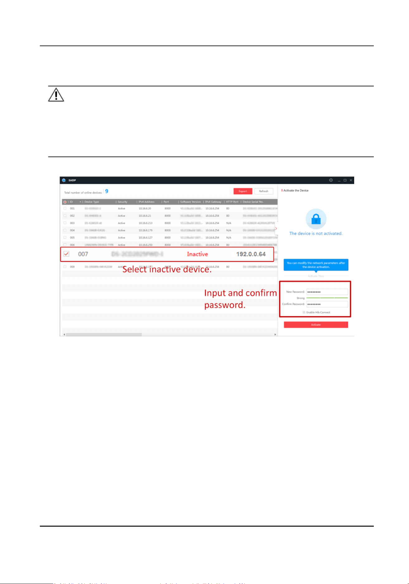
2.
Find and select your device in online device list.
3.
Input new password (admin password) and conrm the password.
Cauon
STRONG PASSWORD RECOMMENDED-We highly recommend you create a strong password of
your own choosing (using a minimum of 8 characters, including upper case leers, lower case
leers, numbers, and special characters) in order to increase the security of your product. And
we recommend you reset your password regularly, especially in the high security system,
reseng the password monthly or weekly can beer protect your product.
4.
Click Acvate to start acvaon.
Status of the device becomes
Acve aer successful acvaon.
5.
Modify IP address of the device.
1) Select the device.
2) Change the device IP address to the same subnet as your computer by either modifying the IP
address manually or checking Enable DHCP.
3) Input the admin password and click Modify to
acvate your IP address modicaon.
4.4
Acvate Device via iVMS-4200 Client Soware
For some devices, you are required to create the password to acvate them before they can be
added to the iVMS-4200
soware and work properly.
DS-K1T502 Series Access Control Terminal User Manual
14
Steps
Note
This funcon should be supported by the device.
1.
Enter the Device Management page.
2.
Click on the right of Device Management and select Device.
3.
Click Online Device to show the online device area.
The searched online devices are displayed in the list.
4.
Check the device status (shown on Security Level column) and select an
inacve device.
5.
Click Acvate to open the Acvaon dialog.
6.
Create a password in the password
eld, and conrm the password.
Cauon
The password strength of the device can be automacally checked. We highly recommend you
change the password of your own choosing (using a minimum of 8 characters, including at least
three kinds of following categories: upper case leers, lower case leers, numbers, and special
characters) in order to increase the security of your product. And we recommend you change
your password regularly, especially in the high security system, changing the password monthly
or weekly can
beer protect your product.
Proper conguraon of all passwords and other security sengs is the responsibility of the
installer and/or end-user.
Note
Characters containing admin and nimda are not supported to be set as acvaon password.
7.
Click OK to acvate the device.
DS-K1T502 Series Access Control Terminal User Manual
15
Chapter 5 Identy Authencaon
Aer network conguraon, system parameters conguraon and user conguraon, you can go
back to the
inial page for identy authencaon. The system will authencate person according
to the congured authencaon mode.
5.1 Authencate via Single Credenal
Set the user authencaon type before authencaon. For details, see .
Authencate ngerprint, card, PIN, or QR code.
Fingerprint
Place the enrolled
ngerprint on the ngerprint module and start authencaon via ngerprint.
Card
Present the card on the card presenng area and start authencaon via card.
Note
The card can be normal IC card, or encrypted card.
QR Code
Put the QR code in front of the device camera to authencate via QR code.
Note
●
Dynamic QR codes need to be authencated within the validity period. Once the QR code is
refreshed, the old QR code will not be authencated.
●
Authencaon via QR code should be supported by the device.
PIN
Enter the PIN to authencate via PIN.
If authencaon completed, a prompt "Authencated" will pop up.
5.2
Authencate via Mulple Credenal
Before You Start
Set the user authencaon type before authencaon. For details, see .
Steps
1.
Authencate any credenal according to the instrucons on the live view page.
DS-K1T502 Series Access Control Terminal User Manual
16

Note
●
The card can be normal IC card, or encrypted card.
●
If the QR Code Scanning funcon is enabled, you can put the QR code in front of the device
camera to authencate via QR code.
2.
Aer the previous credenal is authencated, connue authencate other credenals.
Note
For detailed informaon about scanning ngerprint, see Tips for Scanning Fingerprint.
If authencaon succeeded, the prompt "Authencated" will pop up.
DS-K1T502 Series Access Control Terminal User Manual
17

Chapter 6 Call and Video Intercom
Set the SIP server IP, calling and video intercom between devices are available.
Set Device A as SIP server, and set Device A's IP as SIP server IP. For details, see . All other devices
that need to call each other should be registered to the server.
Set device room number. For details, see
Set Device No. via Web .
On the device main page, enter the device room No. to call. When the other device is answered,
video intercom can be performed.
DS-K1T502 Series Access Control Terminal User Manual
18

Chapter 7 Operaon via Web Browser
7.1 Login
You can login via the web browser or the remote conguraon of the client soware.
Note
Make sure the device is acvated. For detailed informaon about acvaon, see Acvaon .
Login via Web Browser
Enter the device IP address in the address bar of the web browser and press Enter to enter the
login page.
Enter the device user name and the password. Click Login.
Login via Remote
Conguraon of Client Soware
Download and open the client soware. Aer adding the device, click to enter the Conguraon
page.
7.2 Forget Password
If you forget the password when logging in, you can change the password by email address or
security
quesons.
On the login page, click Forget Password.
Select
Vericaon Mode.
Security Queson Vericaon
Answer the security quesons.
E-mail Vericaon
1. Export the QR code and send it to pw_rec[email protected] as aachment.
2. You will receive a vericaon code within 5 minutes in your reserved email.
3. Enter the vericaon code into the vericaon code eld to verify your idencaon.
Click Next, create a new password and conrm it.
7.3 Download Web Plug-In
Both non-Plug-in live view and live view
aer downing plug-in are available. For beer live view,
downloading plug-in for live view is recommended.
Click
→ Download Web Pug-In to download the pulg-in to the local.
DS-K1T502 Series Access Control Terminal User Manual
19

7.4 Help
7.4.1 Open Source Soware Licenses
You can view open source soware licenses.
Click → Open Source Soware Statement on the upper-right corner to view the licenses.
7.4.2 View Online Help Document
You can view the help document for Web conguraon.
Click → Online Document on the upper right of the Web page to view the document.
7.5 Logout
Log out the account.
Click admin → Logout → OK to logout.
7.6 Quick
Operaon via Web Browser
7.6.1 Set Security Queson
If you forget the device acvaon password, you can change the password via security quesons
and E-mail. Set the security quesons before conguraon.
Click in the top right of the web page to enter the Change Password page.
Security Queson Vericaon
Answer the security quesons.
E-mail Vericaon
1. Export the QR code and send it to pw_rec[email protected] as aachment.
2. You will receive a vericaon code within 5 minutes in your reserved email.
3. Enter the vericaon code into the vericaon code eld to verify your idencaon.
click Next. Or you can click Skip to skip the step.
7.6.2 Select Language
You can select a language for the device system.
DS-K1T502 Series Access Control Terminal User Manual
20

Click in the top right of the web page to enter the Device Language Sengs page. You can
select a language for the device system from the drop-down list.
By default, the system language is English.
Note
Aer you change the system language, the device will reboot automacally.
7.6.3 Time Sengs
Click in the top right of the web page to enter the wizard page.
Device Time
Display the device
me in real me.
Time Zone
Select the device located me zone from the drop-down list.
Time Synchronizaon Mode
NTP
You should set the NTP server's IP address, port No., and interval.
Manual
By default, the device me should be synchronized manually. You can set the device me
manually or check Sync. with Computer Time to synchronize the device me with the
computer's
me.
DST
You can enable DST, set and view the DST start me, end me and bias me.
Click Next to save the sengs and go to the next parameter. Or click Skip to skip me sengs.
7.6.4 Privacy
Sengs
Set the picture uploading and storage parameters.
Click in the top right of the web page to enter the wizard page. Aer seng device language,
me and environment, you can click Next to enter the Privacy Sengs page.
Picture Uploading and Storage
Upload Picture Aer Linked Capture
Upload the pictures captured by linked camera to the plaorm automacally.
Save Pictures Aer Linked Capture
If you enable this funcon, you can save the picture captured by linked camera to the device.
Click Next to save the sengs and go to the next paramater. Or click Skip to skip privacy sengs.
DS-K1T502 Series Access Control Terminal User Manual
21
7.6.5 No. and System Network
Steps
1.
Click
in the top right of the web page to enter the wizard page. Aer previous sengs, you
can click Next to enter the No. and Network System Network sengs page.
2.
Set the device type.
Note
●
If set the device type as Door Staon, you can set the Floor No., Door Staon No.,
Community No., Building No., Unit No., Floor No., and Door Staon No..
●
If set the device type as Outer Door Staon, you can set Outer Door Staon No., and
Community No.
Device Type
The device can be used as a door staon or outer door staon. Select a device type from the
drop-down list.
Community No.
Set the device community No.
Building No.
Set the device building No.
Unit No.
Set the device unit No.
Floor No.
Set the device installed
oor No.
Door Staon No.
Set the device installed door staon No.
Note
The main door staon No. is 0, and the sub door staon No. ranges from 1 to 16.
Outer Door Staon No.
Set the device installed outer door staon No.
Note
The No. ranges from 1 to 99.
3.
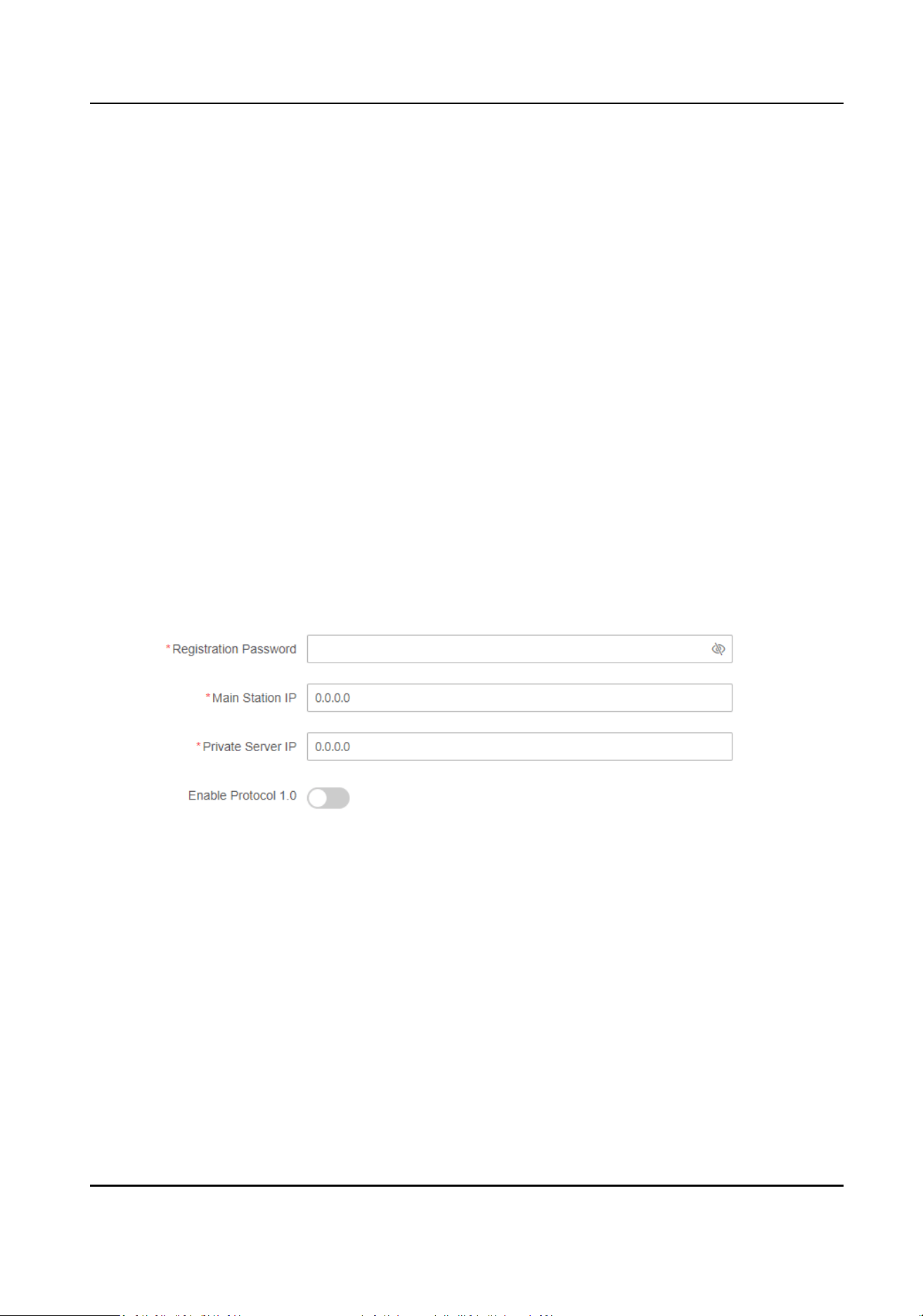
Set the video intercom network parameters.
Registraon Password
Set the registraon password of the main staon for communicaon. Set the registraon
password of the main staon for communicaon.
DS-K1T502 Series Access Control Terminal User Manual
22

Main Staon IP
Enter the main staon’s IP address that used for communicaon.
Private Server IP
Refers to the SIP server IP. Enter the main staon’s IP address that used for communicaon.
At this me the main staon is used as a SIP server. Other intercom devices should registered
to this server address to realize communicaon.
Enable Protocol 1.0
If enabled, the door staon can be registered to the main staon by old protocol version. If
disabled, the door staon can be registered to the main staon by new protocol version.
4.
Click Complete to save the
sengs aer the conguraon.
7.7 Person Management
Click Add to add the person's informaon, including the basic informaon, cercate,
authencaon and sengs.
Add Basic
Informaon
Click Person Management → Add to enter the Add Person page.
Add the person's basic
informaon, including the employee ID, the person's name, gender, and
person type.
If you select Visitor as the person type, you can set the visit mes.
Click Save to save the sengs.
Set Permission Time
Click Person Management → Add to enter the Add Person page.
Enable Long-Term Eecve User, or set Long-Term Eecve User, and the person can only has the
permission within the
congured me period according to your actual needs.
Set the door permission.
Click Save to save the
sengs.
Add Card
Click Person Management → Add to enter the Add Person page.
Click Add Card, enter the Card No. and select the Property, and click OK to add the card.
Click Save to save the
sengs.
Add Fingerprint
Note
Only devices supporng the ngerprint funcon can add the ngerprint.
Click Person Management → Add to enter the Add Person page.
DS-K1T502 Series Access Control Terminal User Manual
23

Click Add Fingerprint, and press your nger on the ngerprint module of the device to add your
ngerprint.
Click Save to save the sengs.
Add PIN
Before conguring passwords, it is necessary to clarify whether the password is a device-set
personal PIN or a plaorm-applied personal PIN. If it is a device-set personal PIN, it can be created
or edited on the device or on the web, and cannot be set on other
plaorms; If it is a plaorm-
applied personal PIN, it can be created or edited on the plaorm, and issued to the device before it
can be used. It cannot be set on the device or on the web.
Click
Conguraon → Security → Password Mode , select PIN Mode as Device-Set Personal PIN.
Click Person Management → Add to enter the Add Person page.
Set the PIN.
Click Save to save the
sengs.
Authencaon
Sengs
Click Person Management → Add to enter the Add Person page.
Set the
authencaon type.
Click Save to save the sengs.
Delete Person
On the person management page, check the person need to delete and click Delete.
Click Clear All to clear all person.
Edit Person
On the person management page, check the person need to edit. Click to edit the person
informaon.
Filter
On the person management page, enter Employee ID / Name / Card No.. Select Credenal Status,
and click Filter to lter the person. Click Reset to clear all condions.
7.8 Access Control Management
7.8.1 Overview
You can view the live video of the device, real-me event, person informaon, network status,
basic informaon, and device capacity.
DS-K1T502 Series Access Control Terminal User Manual
24
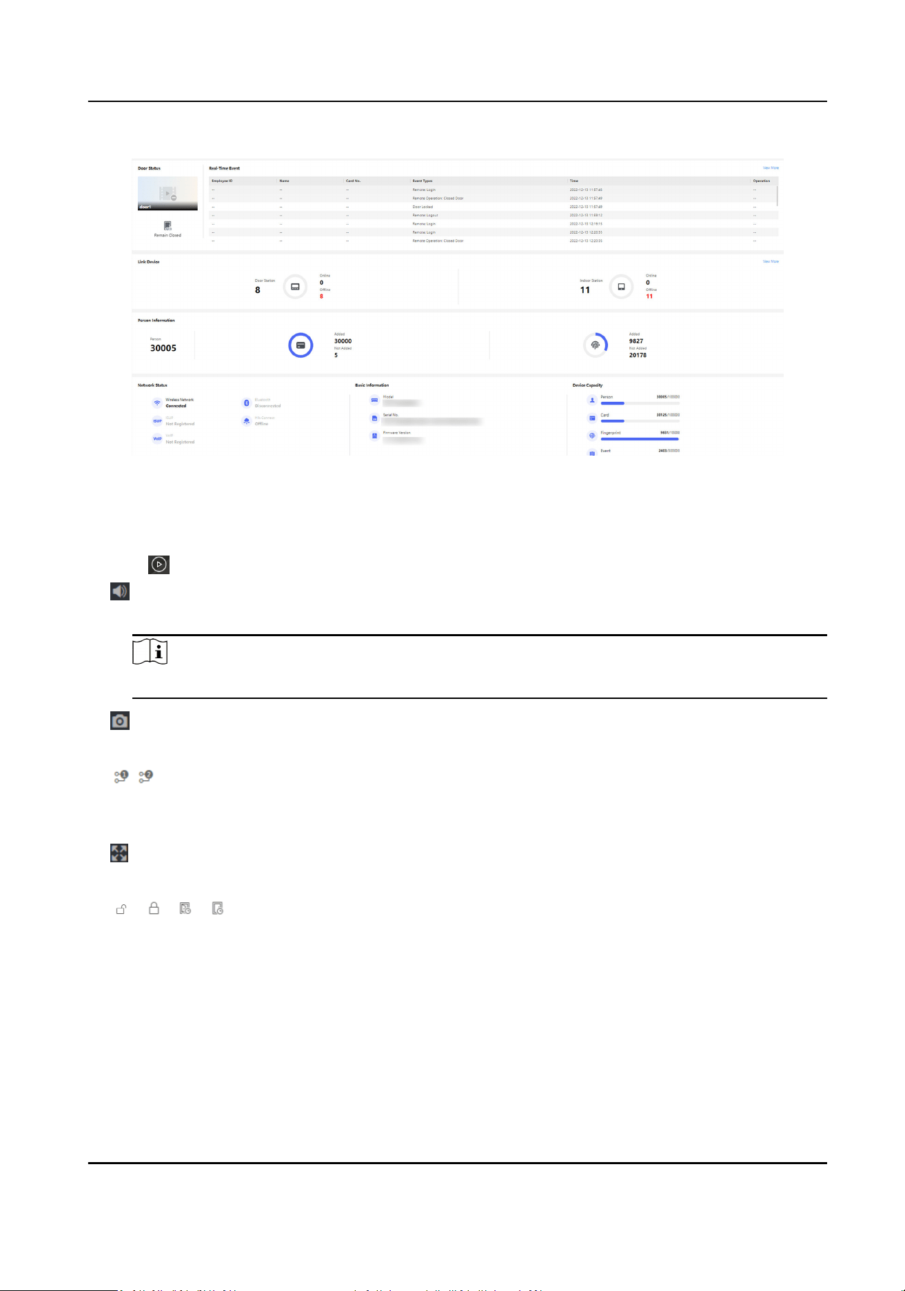
Figure 7-1 Overview Page
Funcon Descripons:
Door Status
Click to view the device live view.
Set the volume when starng live view.
Note
If you adjust the volume when starng two-way audio, you may hear a repeated sounds.
You can capture image when starng live view.
Select the streaming type when starng live view. You can select from the main stream and
the sub stream.
Full screen view.
/ / /
The door status is open/closed/remaining open/remaining closed.
Controlled Status
You can select open/closed/remaining open/remaining closed status according to your actual
needs.
Real-Time Event
DS-K1T502 Series Access Control Terminal User Manual
25
You can view the event Employee ID, Name, Card No., Event Type, Time, and Operaon. You can
also click View More to enter the search condions, including the event type, employee ID, the
name, the card No., the start me, and the end me, and click Search. The results will be
displayed on the right panel.
Person Informaon
You can view the added and not added informaon of person, card, and ngerprint.
Network Status
You can view the connected and registered status of wired network, wireless network,
bluetooth, ISUP, VoIP and cloud service.
Basic
Informaon
You can view the model, serial No. and rmware version.
Device Capacity
You can view the person, card, event and ngerprint capacity.
Note
Only devices supporng ngerprint funcon can display the ngerprint capacity.
View More
You can click View More to view the event details.
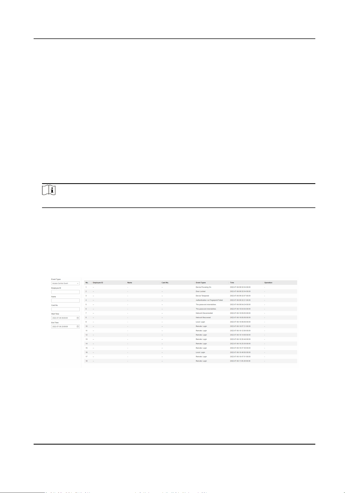
7.8.2 Search Event
Click Event Search to enter the Search page.
Figure 7-2 Search Event
Enter the search condions, including the event type, the employee ID, the name, the card No., the
start
me, and the end me, and click Search.
The results will be displayed on the right panel.
DS-K1T502 Series Access Control Terminal User Manual
26

7.8.3 Door Parameter Conguraon
Congure parameters for unlocking doors.
Set Door Name
Create door name.
Click Access Control → Parameter Sengs → Door Parameters to enter the sengs page.
Set Door Name and click Save.
Set Open
Duraon via PC Web
You can set the me for the door lock to open aer swiping the card.
Click Access Control → Parameter
Sengs → Door Parameters to enter the sengs page.
Set the open duraon, that is the acon me aer the door is unlocked. If the door is not opened
within the set
me, the door will automacally lock. Congurable me: 1 to 255 seconds.
Click Save.
Set Door Open Timeout Alarm via PC Web
If the door is not closed aer reaching the lock acon me, the access control point will sound an
alarm.
Click Access Control → Parameter
Sengs → Door Parameters to enter the sengs page.
Set Door Open Timeout Alarm. If the door is not closed aer reaching the lock acon me, the
access control point will sound an alarm. When set as 0, alarm will not be enabled.
Click Save.
Set Door
Magnec Sensor Type via PC Web
You can select door contact type according to the wiring method.
Click Access Control → Parameter Sengs → Door Parameters to enter the sengs page.
Select magnec sensor type as remain closed or remain open. By default, it is Remain Closed
(excluding special needs).
Click Save.
DS-K1T502 Series Access Control Terminal User Manual
27

Set Exit Buon via PC Web
Set the exit buon as remain open or remain closed according to the actual wiring method.
Click Access Control → Parameter
Sengs → Door Parameters to enter the sengs page.
Set Exit Buon Type. By default, it is Remain Open (excluding special needs).
Click Save.
Set Extended Open Duraon via PC Web
The door contact can be enabled with appropriate delay aer person with extended access needs
swipes her/his card.
Click Access Control → Parameter
Sengs → Door Parameters to enter the sengs page.
Set Extended Open Duraon. The door contact can be enabled with appropriate delay aer person
with extended access needs swipes her/his card.
Click Save.
Set Door Remain Open
Duraon with First Person via PC Web
Aer the rst person is authorized, it allows mulple persons access the door or other
authencaon acons.
Click Access Control → Parameter Sengs → Door Parameters to enter the sengs page.
Set the door open duraon when rst person is in and click Save.
Set Duress Code via PC Web
Aer conguring duress code, when encountering duress, enter the code to open the door. At the
same me, the access control system will report duress events.
Click Access Control → Parameter
Sengs → Door Parameters to enter the sengs page.
Set duress code, and click Save.
Note
Duress code and super password can’t be duplicated, usually consisng of 4 to 8 digits.
Set Super Password via PC Web
Administrator or designated person can enter the super password to open the door.
Click Access Control → Parameter
Sengs → Door Parameters to enter the sengs page.
Set Super Password, the designated person can enter the super password to open the door.
DS-K1T502 Series Access Control Terminal User Manual
28

Click Save.
Note
Duress code and super password can’t be duplicated, usually consisng of 4 to 8 digits.
Set Dismiss Code via PC Web
The administrator or specied person can enter the dismiss code to dismiss the alarm.
Click Access Control → Parameter
Sengs → Door Parameters.
Create a Dismiss Code. When an alarm is triggered, you can enter the dismiss code to dismiss the
alarm.
Click Save.
DS-K1T502 Series Access Control Terminal User Manual
29
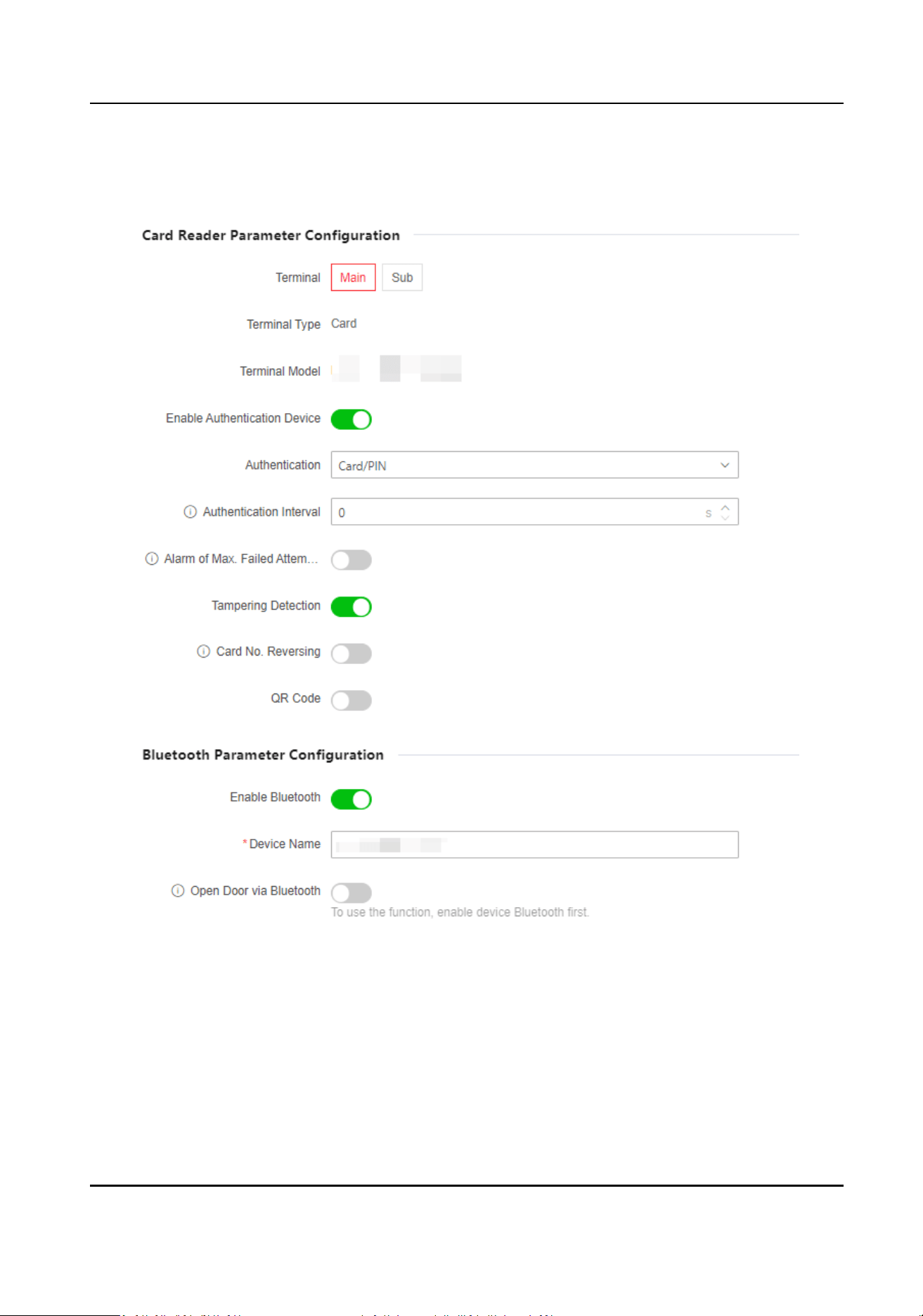
7.8.4 Authencaon Sengs
Figure 7-3 Authencaon Sengs
Select Main or Sub Card Reader via PC Web
Set the terminal for person authencaon.
DS-K1T502 Series Access Control Terminal User Manual
30

Click Access Control → Parameter Sengs → Authencaon Sengs to enter the sengs page.
Select the terminal as main or sub card reader.
Set other parameters and click Save.
View Terminal Type and Model via PC Web
You can view terminal type and model.
Click Access Control → Parameter Sengs → Authencaon Sengs to enter the sengs page.
View Terminal Type and Terminal Model.
Enable
Authencaon Device via PC Web
Aer enabling, the authencaon terminal can be used for card swiping.
Steps
1.
Click Access Control → Parameter Sengs → Authencaon Sengs to enter the sengs
page.
2.
Enable
Authencaon Device. Aer enabling, the terminal can be used for card swiping
normally.
3.
Click Save.
Set
Authencaon via PC Web
Congure Cercaon.
Click Access Control → Parameter Sengs → Authencaon Sengs to enter the sengs page.
When selecng main card reader as the Terminal, you can select Authencaon from the drop-
down list. When there is more than one
authencaon, you should set Single Credenal
Authencang Timeout and Control Inial Authencaon Type.
Single
Credenal Authencang Timeout
You can congure the duraon for each cercaon.
Note
The password authencang meout is 20 s by default, which is not limited by above sengs.
Control Inial Authencaon Type
If enabled, all selected types can be used for rst-me authencaon.
When selecng sub card reader as the Terminal, you can select Authencaon from the drop-
down list.
Click Save.
DS-K1T502 Series Access Control Terminal User Manual
31

Set Authencaon Interval via PC Web
You can set the authencaon interval of the same person when authencang. The same person
can only
authencate once in the congured interval. A second authencaon will be failed. If
other person authencate in the congured interval, the person can authencate again.
Click Access Control → Parameter Sengs → Authencaon Sengs to enter the sengs page.
When you select the terminal as main card reader, set
Authencaon Interval, and click Save.
Enable Alarm of Max. Failed Aempts via PC Web
Enable to report alarm when the card reading aempts reach the set value.
Click Access Control → Parameter Sengs → Authencaon Sengs to enter the sengs page.
When you select the terminal as main or sub card reader, slide to enable Alarm of Max. Failed
Aempts, and set Max. Authencaon Failed Aempts.
Click Save.
Enable/Disable Tampering
Detecon via PC Web
You can enable tampering detecon, the device will automacally generate tampering events
when the card reader is removed or taken away.
Click Access Control → Parameter
Sengs → Authencaon Sengs to enter the sengs page.
Enable or disable Tampering Detecon according to your actual needs. Aer enabling the funcon,
the device will automacally generate tampering events when the card reader is removed or taken
away. If the
funcon is disabled, no alarm events will be generated.
Click Save.
Enable/Disable Card No. Reversing via PC Web
You can enable or disable the card No. reversing funcon.
Click Access Control → Parameter Sengs → Authencaon Sengs to enter the sengs page.
Enable Card No. Reversing, the read card No. will be in reverse sequence.
Click Save.
Enable/Disable QR Code
Recognion via Web Client
You can enable/disable the QR Code recognion funcon.
Click Access Control → Parameter Sengs → Authencaon Sengs to enter the sengs page.
DS-K1T502 Series Access Control Terminal User Manual
32

If the device support QR code recognion, you can enable QR Code and the device can read the QR
code converted from the card No.
Click Save.
Set Communicaon with Controller Every via PC Web
You can set communicaon with controller every of sub card reader. If the card reader can’t
connect with the access controller in the set me, the card reader is oine.
Click Access Control → Parameter Sengs → Authencaon Sengs to enter the sengs page.
When you select the terminal as sub card reader, set Communicaon with Controller Every, and
click Save.
Set Timeout
Duraon of Entering Password via Web Client
Set the maximum interval of entering two characters of the password. Aer entering one
character, if the next character is not entered within the set interval, the entered characters will all
be
automacally cleared.
Click Access Control → Parameter Sengs → Authencaon Sengs to enter the sengs page.
When selecng the sub card reader as the Terminal, you can set Max. Interval When Entering
Password and clickSave.
Set OK LED Polarity and Error LED Polarity via PC Web
Select the polarity of the diodes for OK and ERR interfaces according to actual wiring, with a
default
posive polarity.
Click Access Control → Parameter Sengs → Authencaon Sengs to enter the sengs page.
When you select the terminal as sub card reader, set OK LED Polarity and Error LED Polarity, and
click Save.
Enable/Disable Bluetooth via PC Web
You can enable device bluetooth to connect a bluetooth sound.
Steps
1.
Click Access Control → Parameter Sengs → Authencaon Sengs to enter the sengs
page.
2.
In the bluetooth parameter conguraon secon, enable Enable Bluetooth.
3.
Enter the external sound in the Device Name. Aer the bluetooth is connected, click Save.
4.
Enable Open Door via Bluetooth, you can control the door remotely.
DS-K1T502 Series Access Control Terminal User Manual
33
Note
You should add the device to mobile App before operaon.
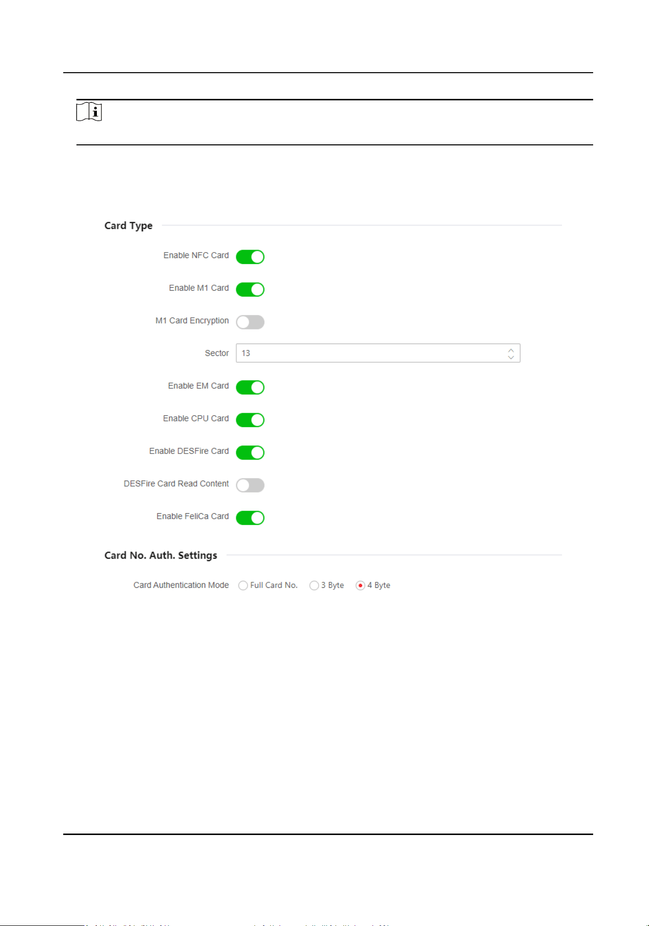
7.8.5 Card Sengs
Figure 7-4 Card Sengs
Enable/Disable NFC
Protecon via PC Web
Aer enabling, the device can read NFC card.
Click Access Control → Parameter Sengs → Card Sengs to enter the sengs page.
Click to Enable NFC Card and click Save. Aer enabling, the device can read NFC card. If the data of
access control devices is obtained by mobile devices, the
situaon of unauthencated access may
occur. To prevent this situaon, you can disable NFC funcon.
DS-K1T502 Series Access Control Terminal User Manual
34
Enable/Disable M1 Card via Web Client
Aer enabling, the device can recognize M1 card and users can swipe M1 card via the device.
Click Access Control → Parameter
Sengs → Card Sengs to enter the sengs page.
Click to Enable M1 Card.
M1 Card Encrypon
Enable M1 Card Encrypon can improve the security level of the entrance card. Therefore, the
entrance card will be harder to be copied.
Sector
Aer enabling M1 Card Encrypon, you will need to set the encrypted sector.
Note
You are advised to encrypt sector 13.
Click Save.
Enable/Disable EM Card via Web Client
Aer enabling, the device can recognize EM card and users can swipe EM card via the device.
Click Access Control → Parameter Sengs → Card Sengs to enter the sengs page.
Click to Enable EM Card and click Save.
Note
If the peripheral card reader which can read EM card is connected, aer enabling this funcon, you
can also swipe EM card via this card reader.
Enable/Disable CPU Card via Web Client
Aer enabling, the device can recognize CPU card and users can swipe CPU card via the device.
Click Access Control → Parameter
Sengs → Card Sengs to enter the sengs page.
Click to Enable CPU Card.
Click to Enable CPU Card Read Content.
Aer enabling, the device can read content from CPU
card.
Click Save.
Aer enabling, the device can read DESFire card.
Click Access Control → Parameter Sengs → Card Sengs to enter the sengs page.
Enable Enable DESFire Card.
Enable DESFire Card Read Content and click Save.
Aer enabling, the device can read DESFire card.
DS-K1T502 Series Access Control Terminal User Manual
35

Aer enabling, the device can read FeliCa card.
Click Access Control → Parameter Sengs → Card Sengs to enter the sengs page.
Enable Enable FeliCa Card.
Click Save. Aer enabling, the device can read FeliCa card.
Congure Card Authencaon Mode via Web Browser
You can set the card number content that the device reads when authencang by card number.
Click Parameter Sengs → Card Sengs to enter the sengs page.
Select card
authencaon mode and click Save.
Full Card No.
All card No. will be read.
3 Byte
The device only read 3 bytes.
4 Byte
The device only read 4 bytes.
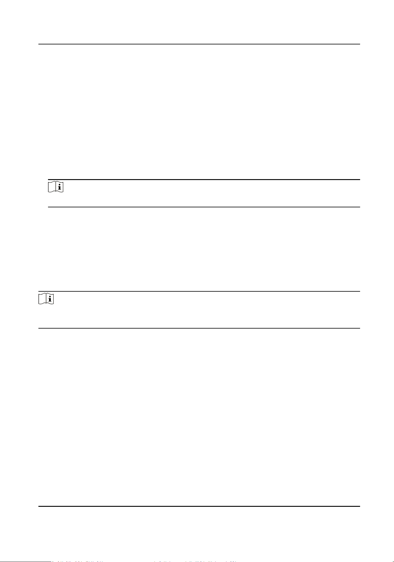
7.8.6 Linkage
Sengs
When the congured event is triggered, upload the event informaon to the central plaorm
according to the congured method.
Steps
1.
Click Access Control → Parameter Sengs → Linkage Sengs to enter the sengs page.
DS-K1T502 Series Access Control Terminal User Manual
36
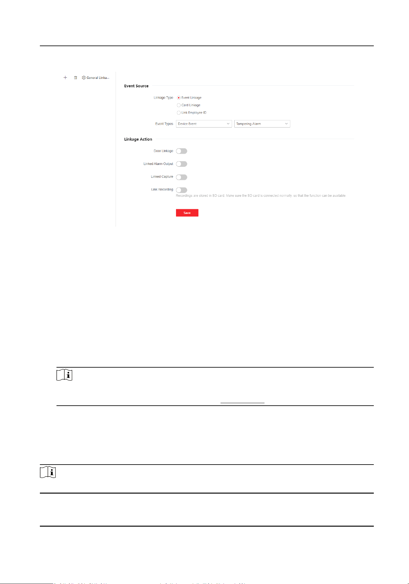
Figure 7-5 Linkage Sengs
2.
Click + .
3.
Set event source. Select the linkage type as Event Linkage, Card Linkage or Link Employee ID.
-
Select Linkage Type as Event Linkage, you can select event types according to your actual
needs.
-
Select Linkage Type as Card Linkage, enter Card No. and select Card reader.
-
Select Linkage Type as Link Employee ID, enter Employee ID and select Card reader.
4.
Set linkage acon.
1) Enable Door Linkage, check and select door acon.
2) Enable Linked Alarm Output, check and select alarm output acon.
3) Enable Linked Capture.
4) Enable Link Recording, click General Linkage
Sengs to set pre-record me and recording
delay, and enable record audio when recording video. Click Save.
Note
To use the recording funcon, you need to prepare the SD card. Aer recording, you can click
Event Search to view recordings. For details, see Search Event
5.
ClickSave to enable the sengs.
7.8.7 Set Working Mode via PC Web
You can set the terminal parameters of the device.
Note
Only some models support this funcon, please refer to the specic device.
DS-K1T502 Series Access Control Terminal User Manual
37

Click Access Control → Parameter Sengs → Terminal Parameters to enter the sengs page.
Working Mode
You can set the working mode as access control mode or permission free mode.
Access Control Mode
The access control mode is the device normal mode. You should authencate your credenal
for accessing.
7.8.8 Set Remote Vericaon
The device will upload the person's authencaon informaon to the plaorm. The plaorm will
judge to open the door or not.
Go to Access Control → Parameter
Sengs → Terminal Parameters.
ClickSave aer parameters are congured.
Remote Vericaon
Aer enabling the remote vericaon, when authencang, the device will upload
authencaon informaon to the plaorm, and the plaorm will conrm whether to open the
door.
DS-K1T502 Series Access Control Terminal User Manual
38
7.8.9 Privacy Sengs
Figure 7-6 Privacy Sengs
Set Event Storage Type via PC Web Browser
You can congure the event storage type.
Click Access Control → Parameter Sengs → Privacy Sengs to enter the sengs page.
You can select Event Storage Type as Delete Old Events Periodically, Delete Old Events by
Specied Time or Overwring.
Delete Old Events Periodically
Drag the block or enter number to set the period for event
deleng. All events will be deleted
according to the congured me duraon.
Delete Old Events by Specied Time
Set a me and all events will be deleted on the congured me.
Overwring
DS-K1T502 Series Access Control Terminal User Manual
39

The earliest 5% events will be deleted when the system detects the stored events has been over
95% of the full space.
Click Save.
Set Picture Uploading and Storage Parameters
Set picture uploading and storage parameters.
Click Access Control → Parameter
Sengs → Privacy Sengs.
Enable the
funcon.
Save Pictures Aer Linked Capture
If you enable this funcon, the captured pictures will be saved to the device automacally.
Click Save.
Clear All Pictures in Device via PC Web
You can clear all captured pictures in the device.
Click Access Control → Parameter Sengs → Privacy Sengs.
Click Clear. All captured pictures will be deleted.
Set PIN Mode via PC Web
Make sure the PIN is plaorm-applied personal PIN or device-set personal PIN before sengs. If
the PIN is device-set personal PIN, you can edit the PIN on the device or PC Web, but not set it on
the
plaorm. If the PIN is plaorm-applied personal PIN, you should set the PIN on the plaorm,
but not on the device or PC Web.
Go to Access Control → Parameter
Sengs → Privacy Sengs.
In the PIN Mode module, you can set the following parameters. Click Save aer parameters
sengs.
Plaorm-Applied Personal PIN
You can create the person PIN on the plaorm. You should apply the PIN to the device. You
cannot create or edit the PIN on the device or PC Web.
Device-Set Personal PIN
You can create or edit the PIN on the device or PC Web. You cannot set the PIN on the
plaorm.
Click Save.
DS-K1T502 Series Access Control Terminal User Manual
40
7.9 Video Intercom Sengs
7.9.1 Device Management
You can view the device No., type, IP, serial No., model, version, oor No., room No., No., arming
status, user name, network status and operaon. You can also add indoor staon and sub door
staon on the device management page, and manage, upgrade or delete devices.
Steps
1.
ClickDevice Management.
2.
Click Add.
3.
Select Device Type, enter Device Password,
Registraon Password, Serial No., IP Address, IPv4
Subnet Mask, IPv4 Default Gateway, Port, Floor No., and No. (not needed to enter Floor No.,
and No. for indoor
staon, but Room No. is needed) .
4.
Click Save.
5.
Oponal: You can also perform the following operaons.
Delete Device Check devices need to delete, and click Delete.
Import Device Click Import, download the template. Aer lling the informaon, click to
import the devices.
Export Device Click Export to export the device informaon les to local PC.
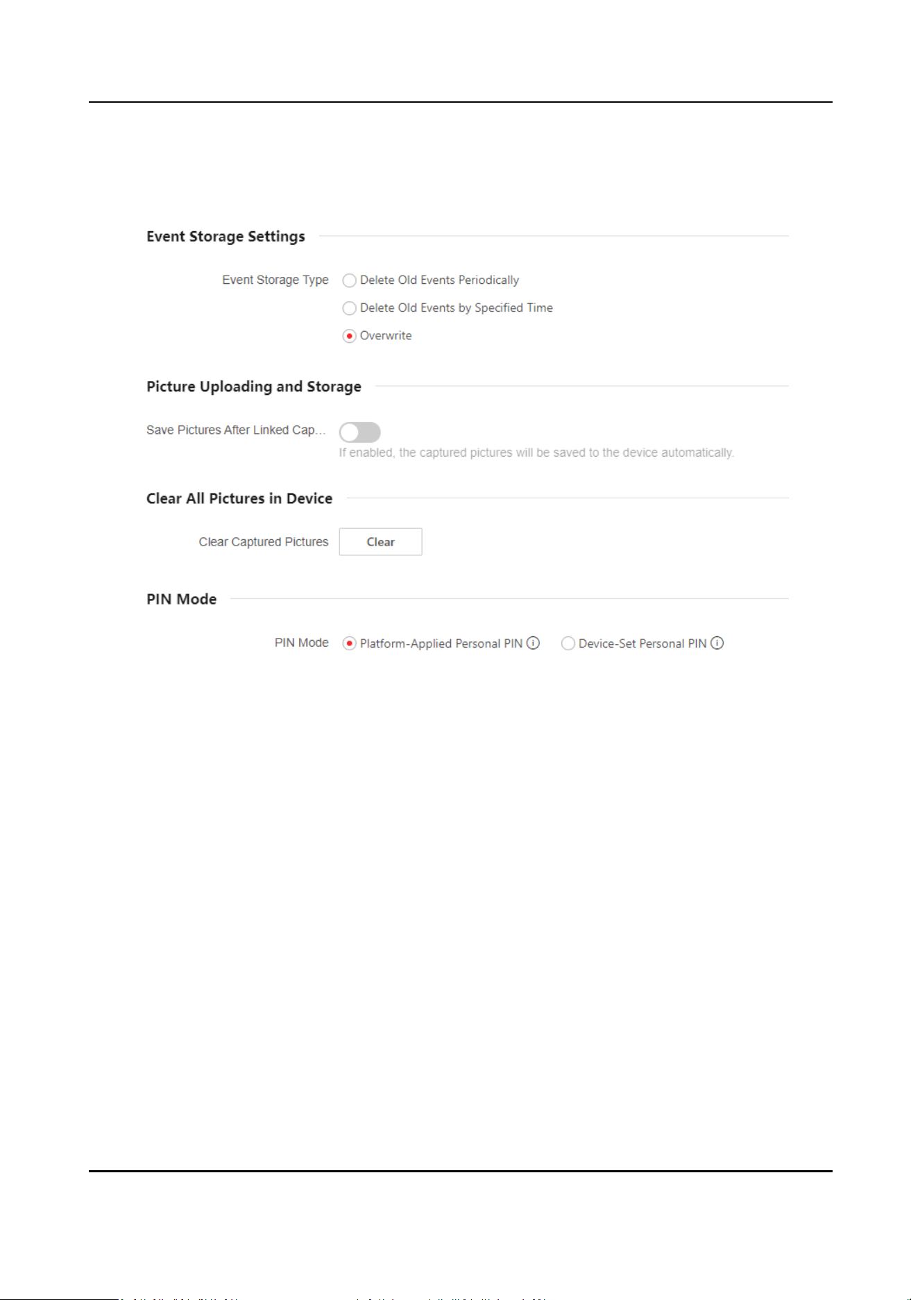
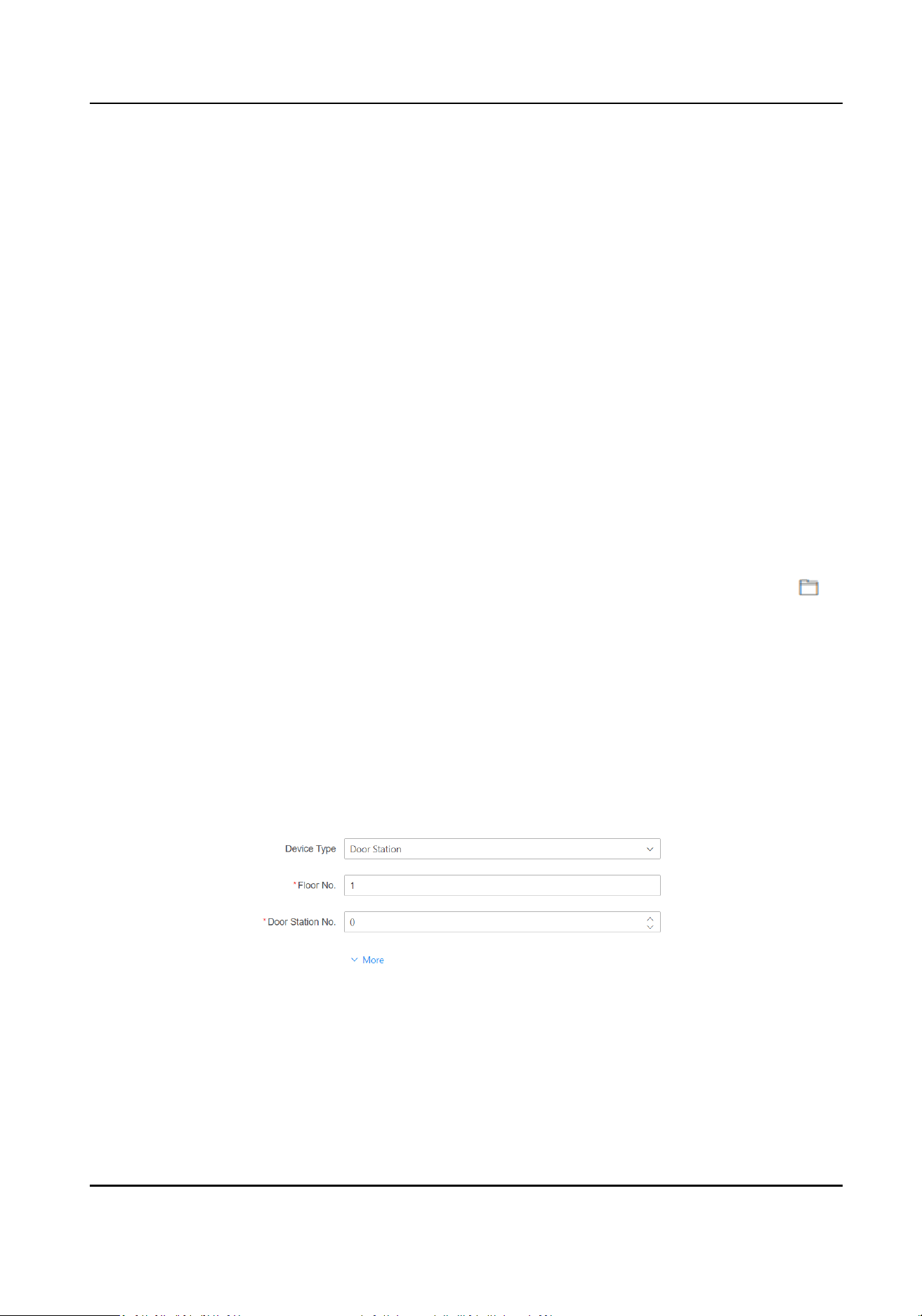
7.9.2 Set Device No. via Web
The device can be used as a door staon or outer door staon. You should set the device No.
before usage.
Click Access Control → Call Sengs → Device No. .
Figure 7-7 Device No. Sengs
If set the device type as Door Staon, you can set the Floor No., Door Staon No., Community
No., Building No., and Unit No.
Device Type
DS-K1T502 Series Access Control Terminal User Manual
41
The device can be used as a door staon or outer door staon. Select a device type from the
drop-down list.
Note
If you change the device type, you should reboot the device.
Floor No.
Set the device installed oor No.
Door Staon No.
Set the device installed oor No.
Note
●
If you change the No., you should reboot the device.
●
The main door staon No. is 0, and the sub door staon No. ranges from 1 to 16.
Community No.
Set the device community No.
Building No.
Set the device building No.
Unit No.
Set the device unit No.
Note
If you change the No., you should reboot the device.
Click Save to save the sengs aer the conguraon.
If set the device type as Outer Door Staon, you can set outer door staon No., and community
No.
Outer Door
Staon No.
If you select outer door staon as the device type, you should enter a number between 1 and
99.
Note
If you change the No., you should reboot the device.
Community No.
Set the device community No.
DS-K1T502 Series Access Control Terminal User Manual
42
7.9.3 Congure Video Intercom Network Parameters via Web Browser
You can set the registraon password, main staon IP and private server IP, and you can enable
protocol 1.0 according to your actual needs.
Click Call
Sengs → Video Intercom Network to enter the sengs page.
Registraon Password
Set the
registraon password of the main staon for communicaon. Set the registraon
password of the main staon for communicaon.
Main Staon IP
Enter the main staon’s IP address that used for communicaon.
Private Server IP
Refers to the SIP server IP. Enter the main staon’s IP address that used for communicaon. At
this me the main staon is used as a SIP server. Other intercom devices should registered to
this server address to realize
communicaon.
Enable Protocol 1.0
If enabled, the door staon can be registered to the main staon by old protocol version. If
disabled, the door staon can be registered to the main staon by new protocol version.
Figure 7-8 Video Intercom Network
Aer conguraon, you can achieve communicaon between access control devices and video
intercom door staon, indoor staon, main staon, plaorms, etc.
Click Save.
7.9.4 Call
Sengs
Set the Max. communicaon me.
Go to Access Control → Call Sengs → Call Sengs.
DS-K1T502 Series Access Control Terminal User Manual
43
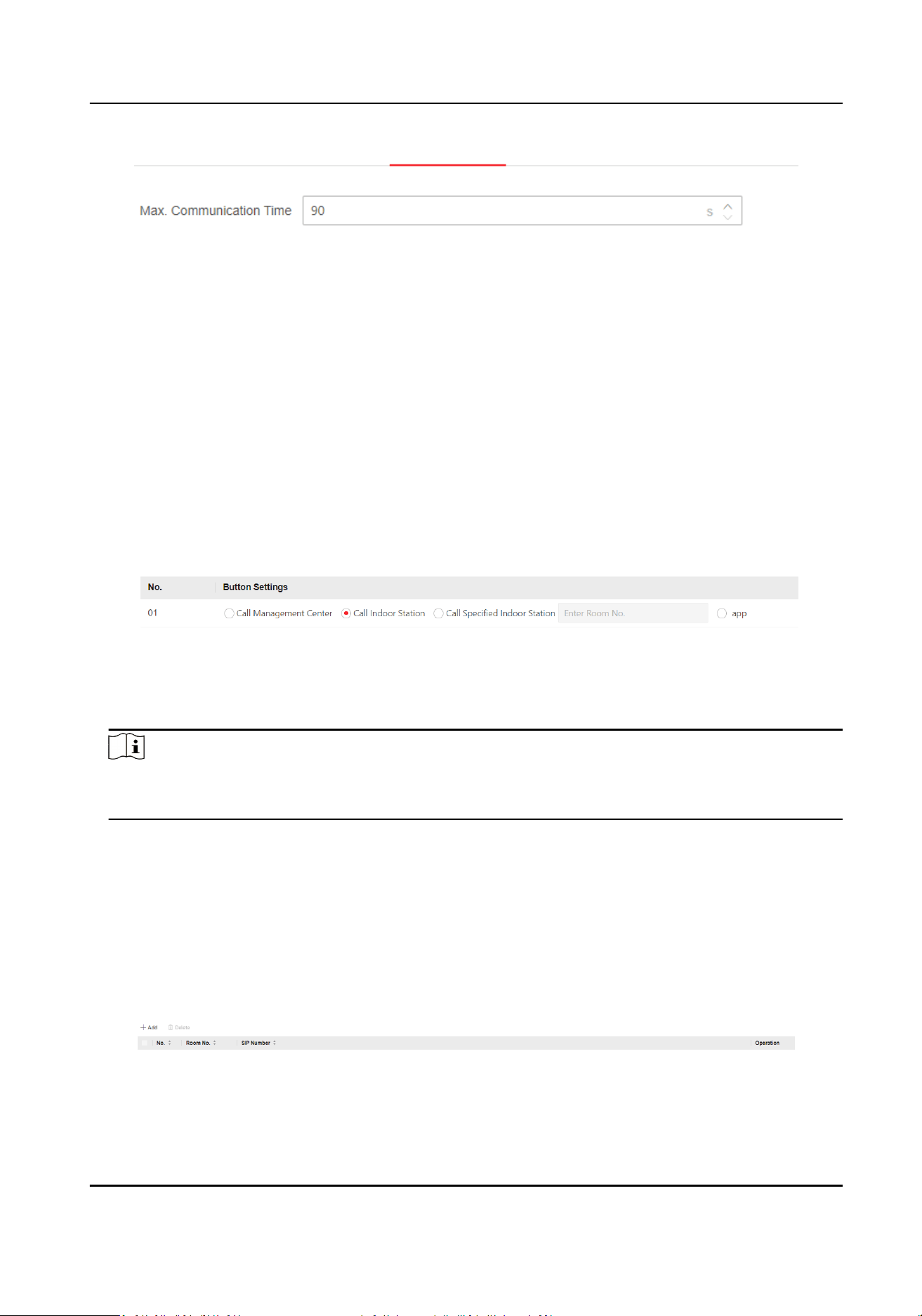
Figure 7-9 Call Sengs
Max. Communicaon Time
The Maximum communicaon me when the main staon and the other devices are in the call.
When the communicaon me exceeds the congured me, the communicaon will stop. The
Max. communicaon me range is 90 s to 120 s.
7.9.5 Set Press
Buon to Call via PC Web
Set the buon linked device for calling.
Steps
1.
Click Access Control → Call Sengs → Press Buon to Call.
Figure 7-10 Press
Buon to Call
2.
Set the buon as Call Management Center, Call Indoor Staon, Call Specied Indoor Staon,or
app.
Note
●
When you check Call Specied Indoor Staon, you should set the linked room’s No.
●
If you check app, you can call HC or HCC.
3.
Click Save.
7.9.6 Number
Sengs via PC Web
Set SIP number for the room. The rooms can communicate with each other via SIP number.
Steps
1.
Go to Access Control → Call Sengs → Number Sengs.
Figure 7-11 Number Sengs
DS-K1T502 Series Access Control Terminal User Manual
44

2.
Click Add, and enter Room No. and SIP1 phone number.
3.
Oponal: Click Add to add the SIP number or click to delete the number.
4.
ClickSave.
5.
Oponal: You can click Delete to delete room number and its SIP number.
7.10 System Conguraon
7.10.1 Set Local Parameters
Set the live view parameters, record le saving path, and captured pictures saving path.
Set Live View Parameters
Click System and Maintenance → Local to enter the Local page. Congure the stream type, the
play performance, auto start live view, and the image format and click Save.
Set Record File Saving Path
Click Conguraon → Local to enter the Local page. Select a record le size and select a saving
path from your local computer and click Save.
You can also click Open to open the
le folder to view details.
Set Captured Pictures Saving Path
Click Conguraon → Local to enter the Local page. Select a saving path from your local computer
and click Save.
You can also click Open to open the
le folder to view details.
7.10.2 View Device
Informaon via PC Web
View the device name, device No., language, model, serial No., version, number of channels, IO
input, IO output, lock, alarm input, alarm output, and device capacity, etc.
Click System and Maintenance → System
Conguraon → System → System Sengs → Basic
Informaon to enter the conguraon page.
You can view the device name, device No., language, model, serial No., version, number of
channels, IO input, IO output, lock, alarm input, alarm output, and device capacity, etc.
Click Upgrade in the Firmware Version, you can go to the upgrade page to upgrade the device.
7.10.3 Set Time
Set the device's me zone, synchronizaon mode, server address, NTP port, and interval.
DS-K1T502 Series Access Control Terminal User Manual
45
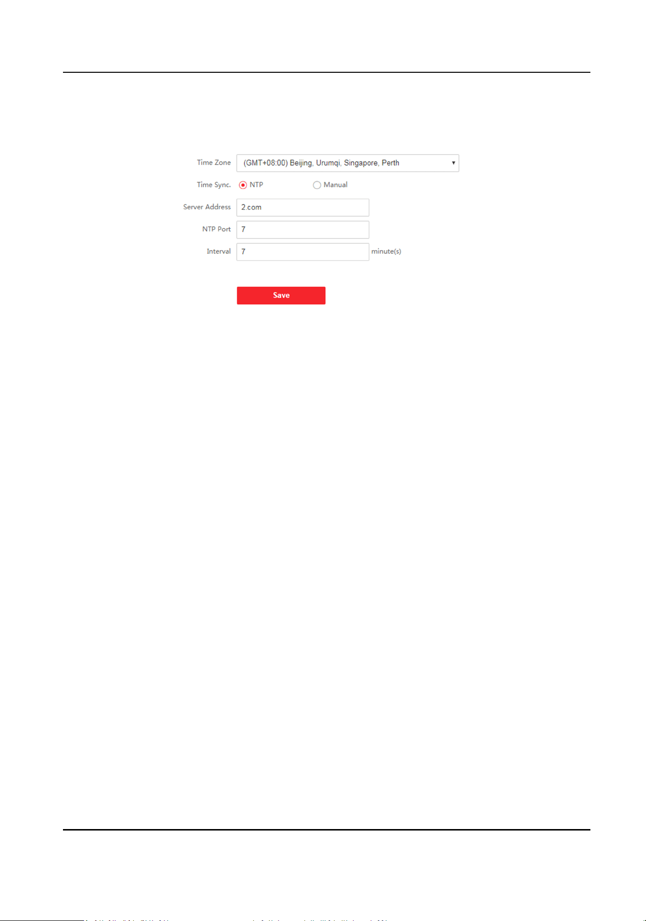
Click System and Maintenance → System Conguraon → System → System Sengs → Time
Sengs .
Figure 7-12 Time Sengs
Click Save to save the sengs aer the conguraon.
Time Zone
Select the device located me zone from the drop-down list.
Time Sync.
NTP
You should set the NTP server's IP address, port No., and interval.
Manual
By default, the device me should be synchronized manually. You can set the device me
manually or check Sync. with Computer Time to synchronize the device me with the
computer's me.
Server Address Type/Server Address/NTP Port/Interval
You can set the server address type, server address, NTP port, and interval.
7.10.4 Set DST
Steps
1.
Click System and Maintenance → System
Conguraon → System → System Sengs → Time
Sengs .
2.
Enable DST.
3.
Set the DST start
me, end me and bias me.
4.
Click Save to save the sengs.
DS-K1T502 Series Access Control Terminal User Manual
46

7.10.5 Change Administrator's Password
Steps
1.
Click System and Maintenance → System
Conguraon → System → User Management →
User Management .
2.
Click .
3.
Enter the old password and create a new password.
4.
Conrm the new password.
5.
Click Save.
Cauon
The password strength of the device can be automacally checked. We highly recommend you
change the password of your own choosing (using a minimum of 8 characters, including at least
three kinds of following categories: upper case leers, lower case leers, numbers, and special
characters) in order to increase the security of your product. And we recommend you change
your password regularly, especially in the high security system, changing the password monthly
or weekly can
beer protect your product.
Proper conguraon of all passwords and other security sengs is the responsibility of the
installer and/or end-user.
7.10.6 Account Security Sengs via PC Web
You can change the security quesons and answers, or the email address for the device. Aer
change the sengs, once you forgot the device password, you should answer the new quesons or
use the new email address to reset the device password.
Steps
1.
Click System and Maintenance → System
Conguraon → System → User Management →
User Management → Account Security Sengs .
2.
Change the security
quesons or email address according your actual needs.
3.
Enter the device password and click OK to conrm changing.
7.10.7 Online Users
The informaon of users logging into the device is shown.
Go to System and Maintenance → System Conguraon → System → User Management →
Online Users to view the list of online users.
7.10.8 View Device Arming/Disarming
Informaon via PC Web
View device arming type and arming IP address.
DS-K1T502 Series Access Control Terminal User Manual
47
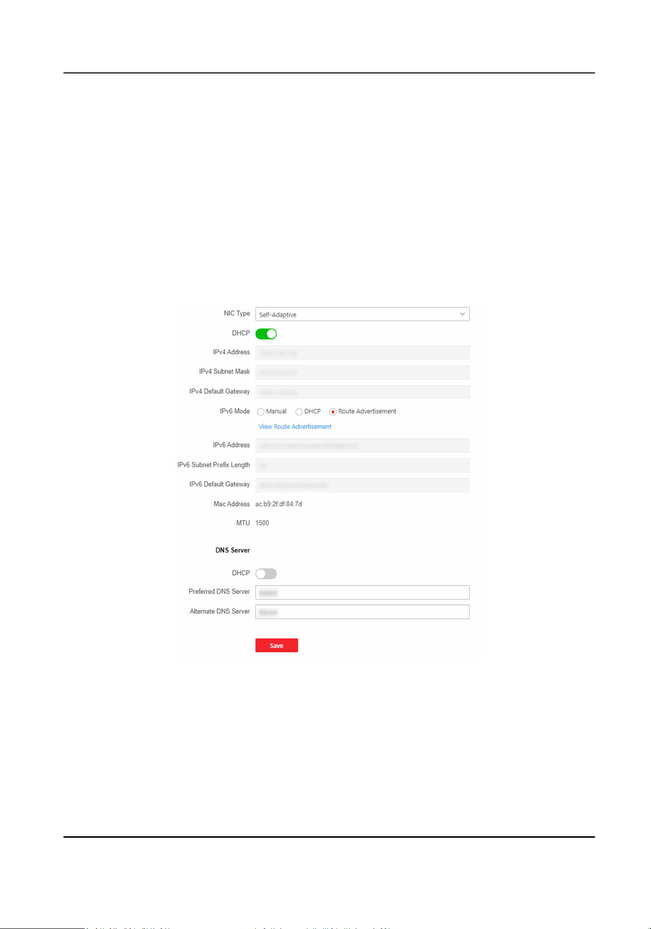
Go to System and Maintenance → System Conguraon → System → User Management →
Arming/Disarming Informaon .
You can view the device arming/disarming informaon. Click Refresh to refresh the page.
7.10.9 Network Sengs
Set Basic Network Parameters
Click System and Maintenance → System Conguraon → Network → Network Sengs →
TCP/IP .
Figure 7-13 TCP/IP Sengs Page
Set the parameters and click Save to save the sengs.
NIC Type
Select a NIC type from the drop-down list. By default, it is Auto.
DHCP
DS-K1T502 Series Access Control Terminal User Manual
48
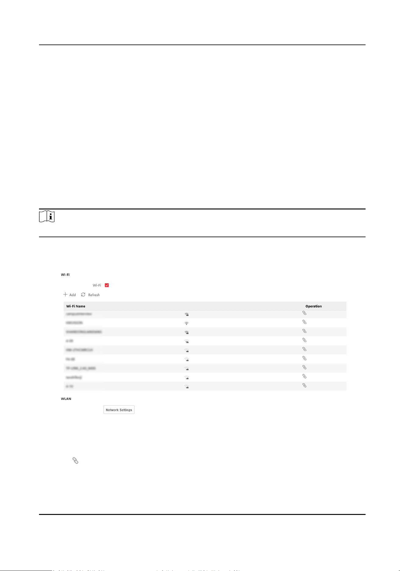
If uncheck the funcon, you should set the IPv4 address, IPv4 subnet mask, IPv4 default
gateway, IPv6 mode, IPv6 address, IPv6 subnet prex length, IPv6 default gateway, Mac address,
and MTU.
If you check the funcon, the system will allocate the IPv4 address, IPv4 subnet mask, the IPv4
default gateway, IPv6 mode, IPv6 address, IPv6 subnet prex length, and IPv6 default gateway
automacally.
DNS Server
Set the preferred DNS server and the Alternate DNS server according to your actual need.
Set Wi-Fi Parameters
Set the Wi-Fi parameters for device wireless connecon.
Steps
Note
The funcon should be supported by the device.
1.
Click System and Maintenance → System Conguraon → Network → Network Sengs → Wi-
Fi .
Figure 7-14 Wi-Fi Sengs Page
2.
Check Wi-Fi.
3.
Select a Wi-Fi
-
Click of a Wi-Fi in the list and enter the Wi-Fi password.
-
Click Add and enter a Wi-Fi's name, password, and encrypon type. Click Connect. When the
Wi-Fi is connected, click OK.
DS-K1T502 Series Access Control Terminal User Manual
49
4.
Oponal: Set the WLAN parameters.
1) Set the IP address, subnet mask, and default gateway. Or enable DHCP and the system will
allocate the IP address, subnet mask, and default gateway automacally.
5.
Click Save.
Device Hotspot
Set the device hotspot.
Click System and Maintenance → System Conguraon → Network → Network Sengs →
Device Hotspot .
Click Enable Device Hotspot to enable the
funcon and view the device hotspot name.
Note
By default, the hotspot name is the AP_Device Serial No.
Click Save.
Set Port via PC Web
Click System and Maintenance → System Conguraon → Network → Network Service .
HTTP
It refers to the port through which the browser accesses the device. For example, when the
HTTP Port is
modied to 81, you need to enter hp://192.0.0.65:81 in the browser for login.
HTTPS
Set the HTTPS for accessing the browser. Cercate is required when accessing.
HTTP Listening
The device can send alarm informaon to the event alarm IP address or domain name via HTTP
protocol/HTTPS protocol. Edit the event alarm IP address or domain name, URL, port, and
protocol.
Note
The event alarm IP address or domain name should support the HTTP protocol/HTTPS protocol
to receive the alarm informaon.
Click System and Maintenance → System Conguraon → Network → Network Service → RTSP .
RTSP
It refers to the port of real-me streaming protocol.
DS-K1T502 Series Access Control Terminal User Manual
50
Set ISUP Parameters via PC Web
Set the ISUP parameters for accessing device via ISUP protocol.
Steps
Note
The funcon should be supported by the device.
1.
Click System and Maintenance → System Conguraon → Network → Device Access → ISUP .
2.
Check Enable.
3.
Set the ISUP version, server address, device ID, and the ISUP status.
Note
If you select 5.0 as the version, you should set the encrypon key as well.
4.
Set the ISUP listening parameters, including ISUP alarm center IP address/domain name, ISUP
alarm center URL, and ISUP alarm center port.
5.
Click Save.
Plaorm
Access via PC Web
Plaorm access provides you an opon to manage the devices via plaorm.
Steps
1.
Click System and Maintenance → System
Conguraon → Network → Device Access → Hik-
Connect to enter the sengs page.
Note
Hik-Connect is an applicaon for mobile devices. With the App, you can view live image of the
device, receive alarm nocaon and so on.
2.
Check Enable to enable the funcon.
3.
Oponal: Check the checkbox of Custom, and you can set the server address by yourself.
4.
Enter the vericaon code.
5.
Click View to view device QR code. Scan the QR code to bind the account.
Note
8 to 32 leers (a to z, A to Z) or numbers (0 to 9), case sensive. You are recommended to use a
combinaon of no less than 8 leers or numbers.
6.
Click Save to enable the sengs.
DS-K1T502 Series Access Control Terminal User Manual
51

Bluetooth Sengs
You can enable bluetooth funcon.
Click Conguraon → Network → Network Sengs → Bluetooth .
Open
Enable Open to enable the bluetooth funcon.
Device Name
You can edit the device name connected to the bluetooth.
Connecon Status
You can view the connecon status.
Open Door via Bluetooth
Aer enabling this funcon, you can open doors via HikCentral Connect or HikCentral Access
Control.
Note
You should add devices to the HCC or HCAC before opening door via bluetooth. Via HCAC, you
can also realize the auto door open funcon. for details, see the HCAC's user manual.
VoIP Account Sengs
You can realize voice call by network.
Steps
1.
Go to System and Maintenance → System Conguraon → Network → Device Access → VoIP.
2.
Enable VoIP Gateway.
3.
Set Register User Name、
Registraon Password、Server IP Address、Server Port、Expiry
Time、Register Status、Number、Display User Name.
DS-K1T502 Series Access Control Terminal User Manual
52
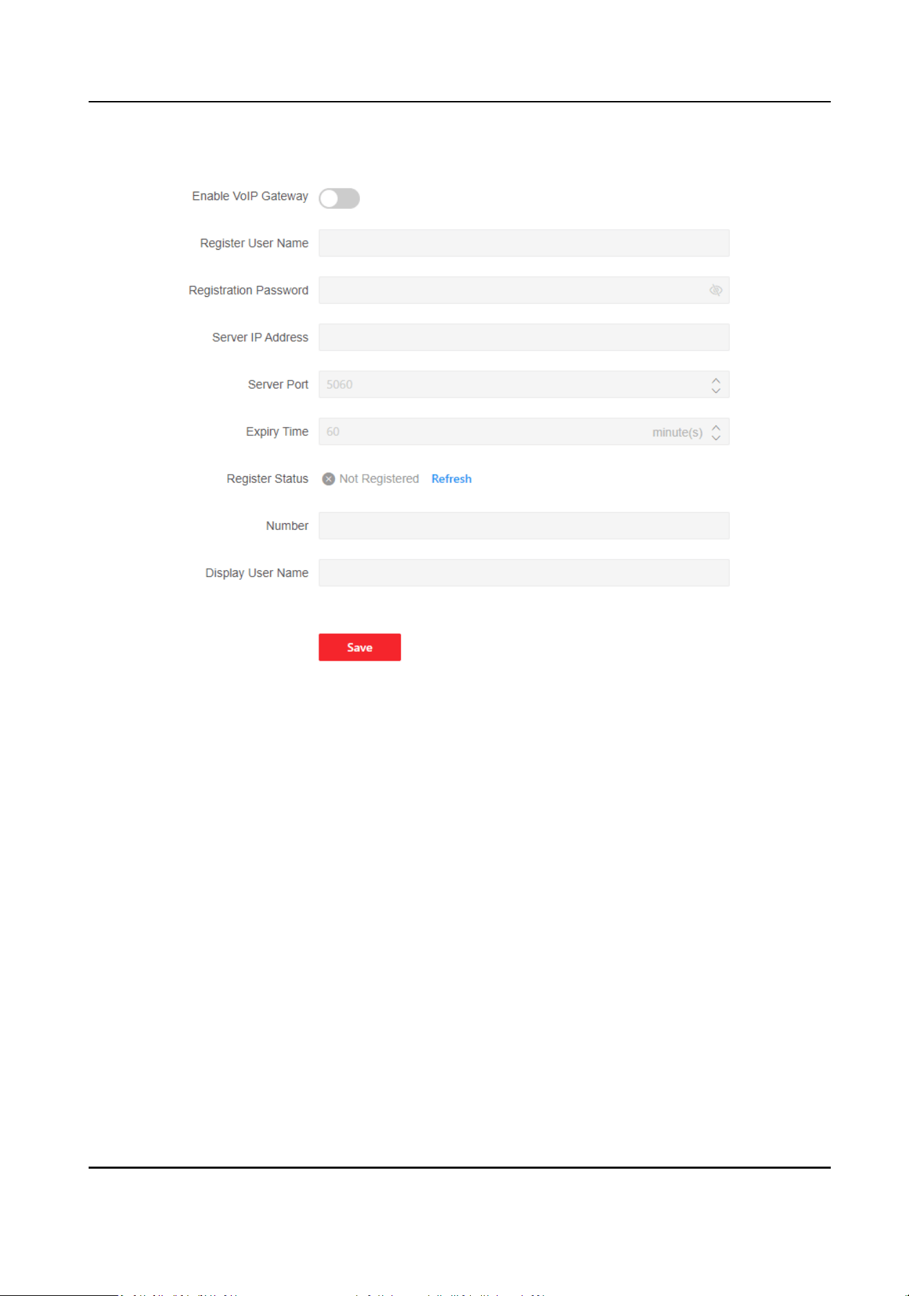
Figure 7-15 VoIP Account Sengs
Registraon Password
Enter the registraon password for communicaon via SIP server. The registraon password
for the SIP server is
congured usually in the main staon’s SIP sengs.
Server IP Address
Enter the main staon’s IP address that used for VoIP communicaon. At this me the main
staon is used as a SIP server. Other intercom devices should registered to this server address
to realize
communicaon.
Number / Display User Name
The device displayed call number and user name.
4.
Click Save.
DS-K1T502 Series Access Control Terminal User Manual
53
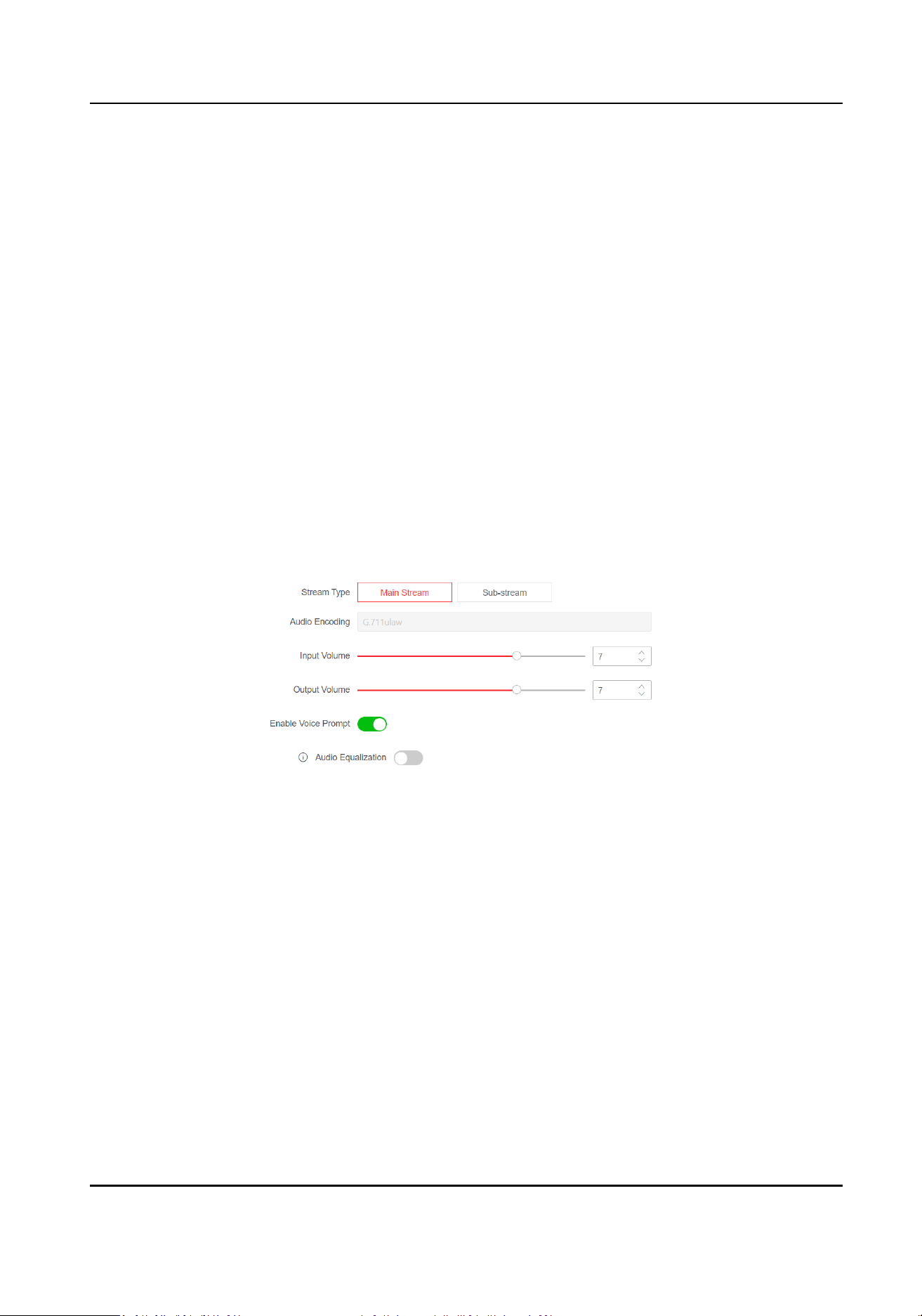
7.10.10 Set Video and Audio Parameters via PC Web
Congure Video Parameters via Web Browser
You can set quality, resoluon and other parameters of device camera.
Click System and Maintenance → System Conguraon → Video/Audio → Video to enter the
sengs page.
Set camera name, stream type, video type,
resoluon, bit rate type, video quality, frame rate, Max.
bitrate, video encoding and I frame interval.
Click Save.
Congure
Audio Parameters via PC Web
You can set device volume.
Go to System and Maintenance → System Conguraon → Video/Audio → Audio.
Figure 7-16 Audio
Set stream type and audio encoding according to your actual needs. Slide to set input and output
volume.
Slide to enable Voice Prompt.
You can enable Audio
Equalizaon, the device wil auto adjust frequency by audio algorithm to
improve audio quality and equalize audio
eect.
Click Save.
DS-K1T502 Series Access Control Terminal User Manual
54
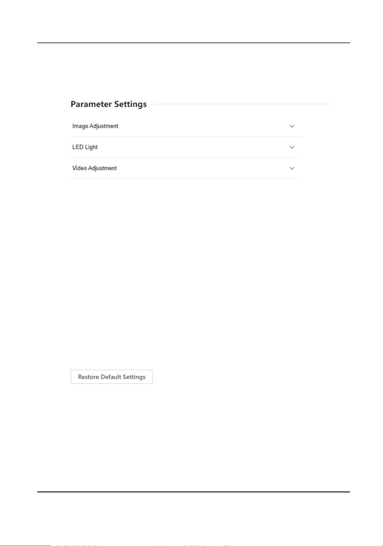
7.10.11 Image Parameters Sengs
Figure 7-17 Display Sengs
DS-K1T502 Series Access Control Terminal User Manual
55

Set Brightness/Contrast/Saturaon/Sharpness via PC Web
You can set picture informaon such as brightness, contrast, saturaon and sharpness of live view
page.
Click System and Maintenance → System
Conguraon → Image → Display Sengs to enter the
sengs page.
Image Adjustment
Drag the block or enter numbers to set brightness, contrast,
saturaon and sharpness.
Click Restore Default Sengs to restore the to the default.
Set LED Light via PC Web
You can adjust the brightness of the supplement light.
Steps
1.
Click System and Maintenance → System Conguraon → Image → Display Sengs to enter
the sengs page.
2.
Set the type, mode and brightness of the supplement light.
3.
Oponal: Click Restore Default Sengs to restore the to the default.
Set Video Standard via PC Web
You can set the video standard of live view page.
Click System and Maintenance → System Conguraon → Image → Display Sengs to enter the
sengs page.
Video Adjustment
Set the video frame rate during remote preview. You need to reboot the device to make the
new
sengs eecve.
PAL
25 frames per second. Suitable for mainland China, Hong Kong (China), the Middle East
countries, Europe countries, etc.
NTSC
30 frames per second. Suitable for the USA, Canada, Japan, Taiwan (China), Korea, the
Philippines, etc.
Click Restore Default
Sengs to restore the to the default.
DS-K1T502 Series Access Control Terminal User Manual
56
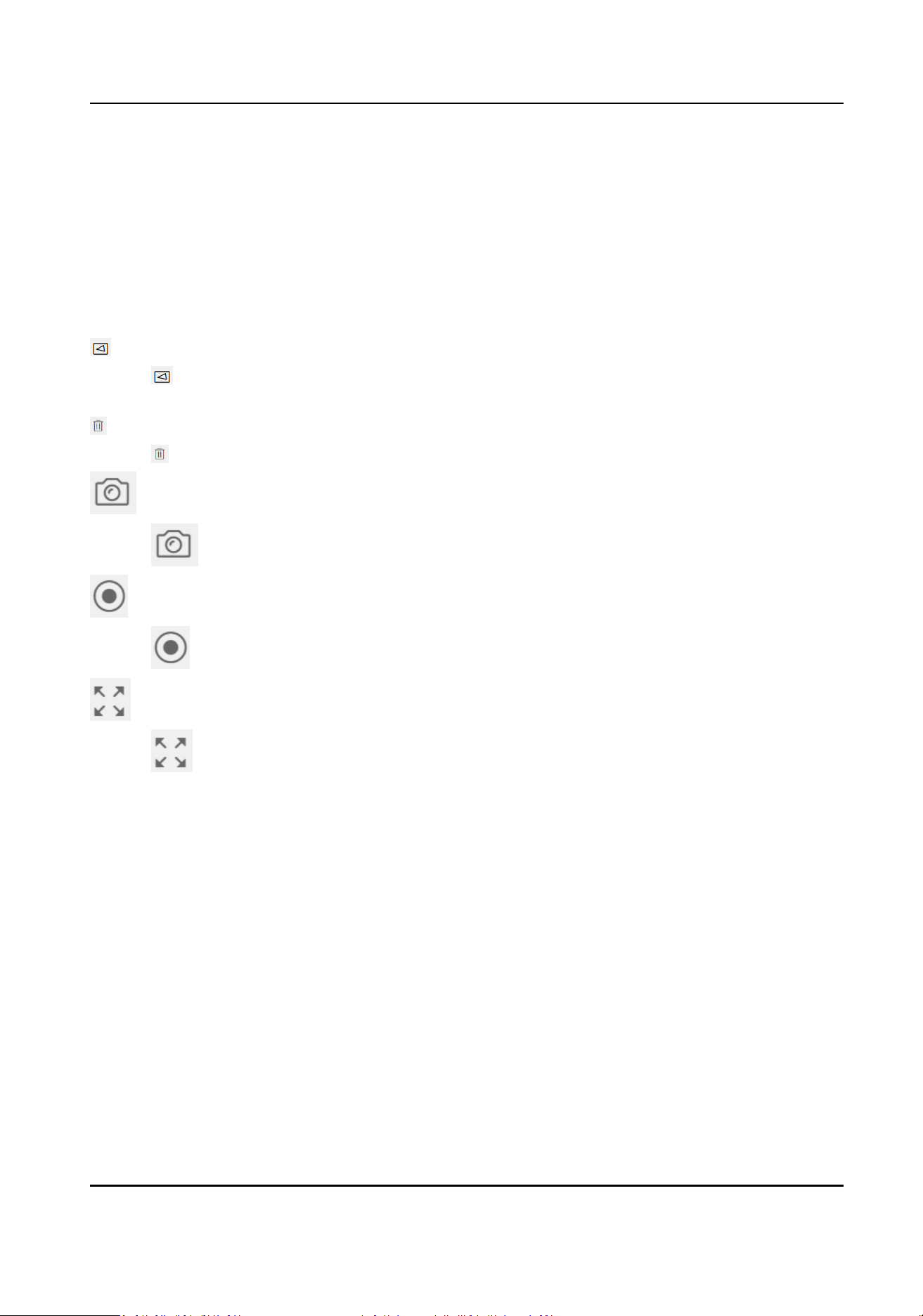
7.10.12 Set Event Detecon via PC Web
Aer seng the moon detecon event, if there is moving objects trigger the rule, the device will
report to the
plaorm.
Click System and Maintenance → System Conguraon → Event → Event Detecon.
Enable Moon.
Set the
moon detecon area on the live view part of the page.
Click , and draw an area in the live view page. When there is moving objects into the area, an
alarm will be triggered.
Click to delete the area.
Click to capture pictures.
Click to start recording. Click again to stop. The recording will be saved to local PC.
Click to view the live view in full screen mode.
Sensivity
Set the sensivity that will trigger the rule. The higher the sensivity, the easier to trigger the
rule.
Arming Schedule
Exit the me schedule.
Click Edit, and click Arm. On the
me schedule, you can draw the arming duraon. Click Save. In
the arming duraon, if there is rule triggered, it will linked to report to plaorm.
Nofy Surveillance Center
Aer enabling the funcon, if there is rules triggered, the device will report to plaorm.
HTTP
Aer enabling the funcon, if there is rules triggered, the device will report to plaorm by HTTP.
Click Save.
DS-K1T502 Series Access Control Terminal User Manual
57
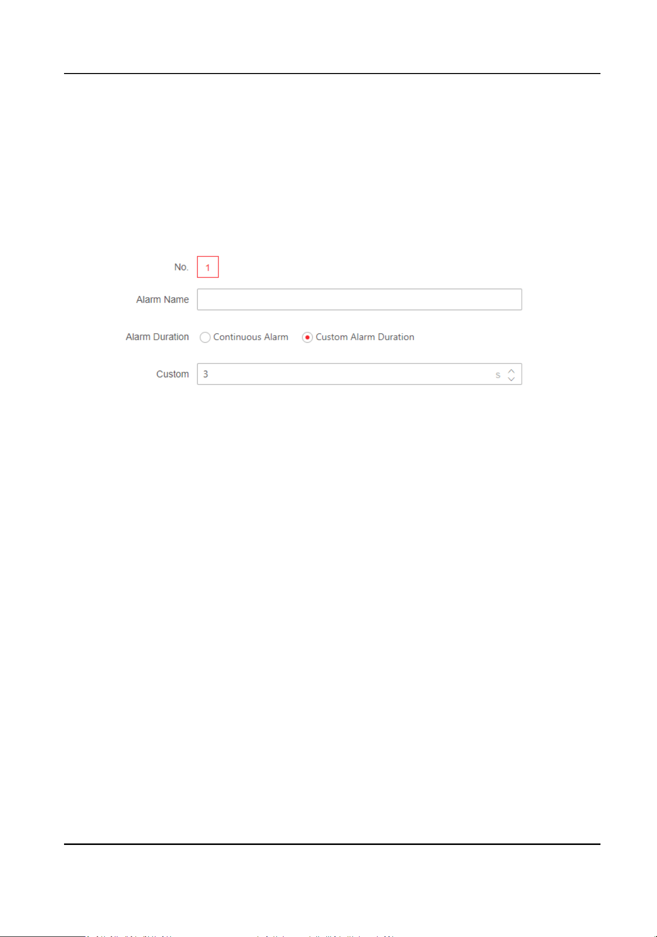
7.10.13 Alarm Sengs via PC Web
Set the alarm output parameters.
Steps
1.
Click System and Maintenance → System Conguraon → Event → Alarm Sengs → Alarm
Output .
2.
Set Alarm Name and mode of Alarm
Duraon.
Figure 7-18 Alarm Sengs
Connuous Alarm
When the alarm is triggered, it will alarm connuously.
Custom Alarm Duraon
You can set Alarm Duraon for the device when the alarm is triggered.
7.10.14 Access
Conguraon
Set RS-485 Parameters via PC Web
You can set the RS-485 parameters including the peripheral, address, baud rate, etc.
Click System and Maintenance → System Conguraon → Access Conguraon → RS-485 .
Select the RS-485's protocol from the drop-down list.
Check Enable RS-485, and set the parameters.
Click Save to save the
sengs aer the conguraon.
No.
Set the RS-485 No.
Peripheral Type
DS-K1T502 Series Access Control Terminal User Manual
58
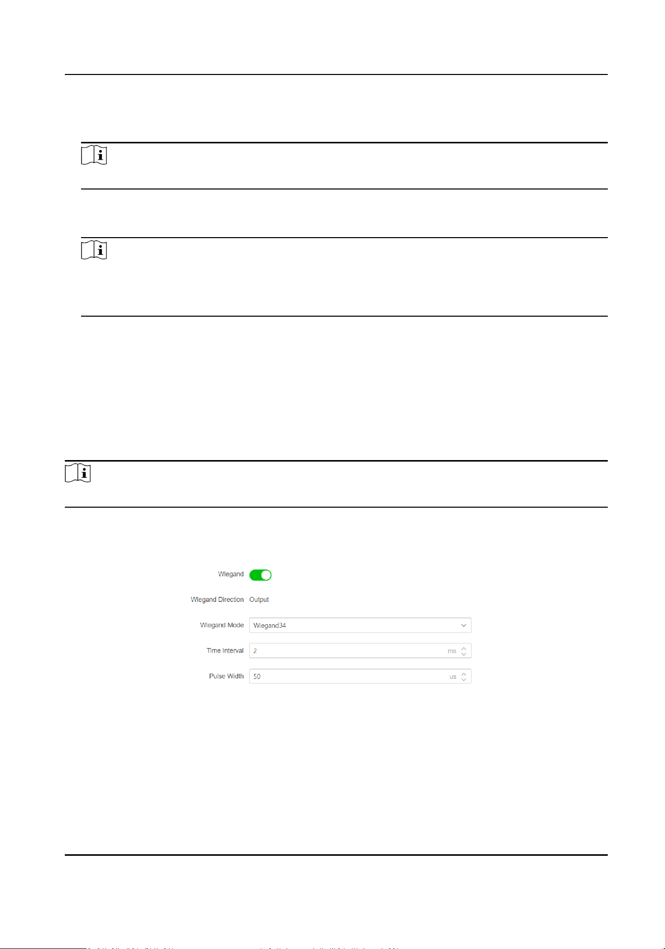
Select a peripheral from the drop-down list according the actual situaon. You can select from
Card Reader, Extension Module, Access Controller, or Disable.
Note
Aer the peripheral is changed and saved, the device will reboot automacally.
RS-485 Address
Set the RS-485 Address according to your actual needs.
Note
If you select Access Controller: If connect the device to a terminal via the RS-485 interface, set
the RS-485 address as 2. If you connect the device to a controller, set the RS-485 address
according to the door No.
Baud Rate
The baud rate when the devices are communicang via the RS-485 protocol.
Set Wiegand Parameters via PC Web
You can set the Wiegand transmission direcon.
Steps
Note
Some device models do not support this funcon. Refer to the actual products when conguraon.
1.
Click System and Maintenance → System Conguraon → Access Conguraon → Wiegand
Sengs .
Figure 7-19 Wiegand Page
2.
Check Wiegand to enable the Wiegand funcon.
3.
Set a transmission direcon.
Output
The can connect an external access controller. And the two devices will transmit the card No.
via Wiegand 26 or 34.
DS-K1T502 Series Access Control Terminal User Manual
59
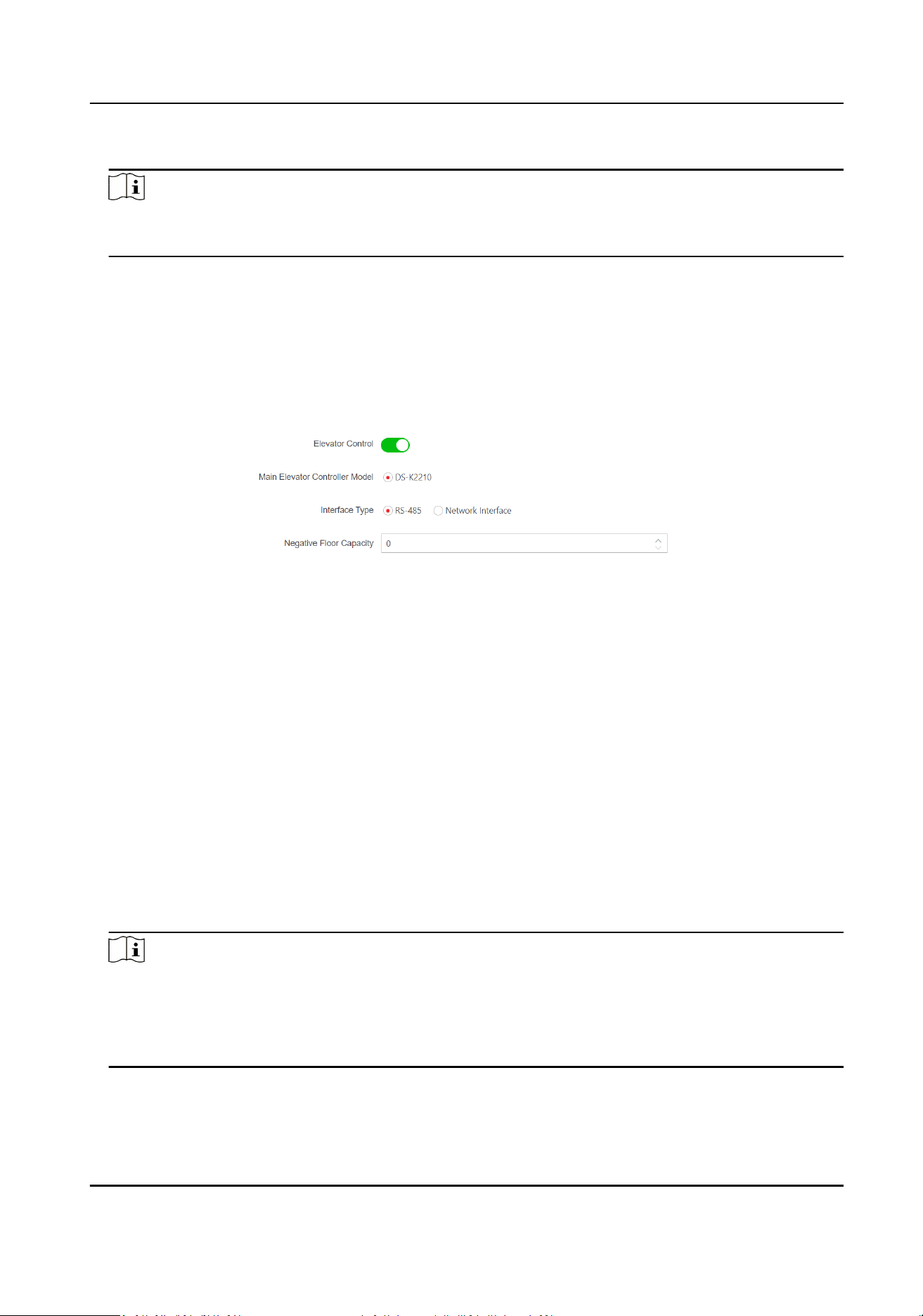
4.
Click Save to save the sengs.
Note
If you change the peripheral, and aer you save the device parameters, the device will reboot
automacally.
Elevator Control via PC Web
Steps
1.
Click System and Maintenance → System Conguraon → Access Conguraons → Elevator
Control Parameters .
Figure 7-20 Elevator Control
2.
Enable Elevator Control.
3.
Set the elevator parameters.
Main Elevator Controller Model
View the elevator model.
Interface Type
Select a
communicaon type from the drop-down list for elevator communicaon.
If you select RS-485, make sure you have connected the device to the elevator controller with
RS-485 wire.
If you select Network Interface, enter the elevator controller's IP address, port No., user
name, and password for
communicaon.
Negave Floor Capacity
Set the negave oor number.
Note
●
Up to 4 elevator controllers can be connected to 1 device.
●
Up to 10 negave oors can be added.
●
Make sure the interface types of elevator controllers, which are connected to the same
device, are consistent.
DS-K1T502 Series Access Control Terminal User Manual
60

7.11 System and Maintenance
7.11.1 Reboot
You can reboot the device.
Click System and Maintenance → Maintenance → Restart to enter the sengs page.
Click Restart to reboot the device.
7.11.2 Upgrade
Upgrade Locally via PC Web
You can upgrade the device locally.
Click System and Maintenance → Maintenance → Upgrade to enter the
sengs page.
Select an upgrade type from the drop-down list. Click and select the upgrade le from your
local PC. Click Upgrade to start upgrading.
Online Upgrading via PC Web
You can upgrade the device online.
Click System and Maintenance → Maintenance → Upgarde to enter the
sengs page.
ClickCheck for Updatesto check whether there is updated versions.
If the device is connected to the network and added to Hik-Connect App, you can tap Device
Upgrade → Online Upgrade on device for upgrading when there is an updated version in Hik-
Connect App.
7.11.3
Restoraon
Restore to Factory Sengs via Web Browser
You can restore device to factory sengs.
Click System and Maintenance → Maintenance → Backup and Reset to enter the sengs page.
Click Restore All, all parameters will be restored to the factory sengs. You should acvate the
device before usage.
DS-K1T502 Series Access Control Terminal User Manual
61
Restore to Default Sengs via PC Web
You can restore device to default sengs.
Click System and Maintenance → Maintenance → Backup and Reset to enter the sengs page.
Click Restore, the device will restore to the default sengs, except for the device IP address and
the user informaon.
7.11.4 Export Device Parameters via PC Web
Export device parameters.
Go to System and Maintenance → Maintenance → Backup and Reset .
Backup
Click Export to export device parameters.
Note
Export device parameters and import those parameters to other devices.
7.11.5 Import Device Parameters via PC Web
Import the conguraon parameters.
Go to System and Maintenance → Maintenance → Backup and Reset .
Import
Cong File
Click and select a le from local PC. Click Import.
7.11.6 Device Debugging
You can set device debugging parameters.
Enable/Disable SSH via Web Browser
You can enable SSH to perform remote debugging.
Click System and Maintenance → Maintenance → Device Debugging → Log for Debugging.
Enable SSH
SSH is used for remote debugging. When you don’t need to use this service, it’s recommended
to disable SSH to improve security.
DS-K1T502 Series Access Control Terminal User Manual
62
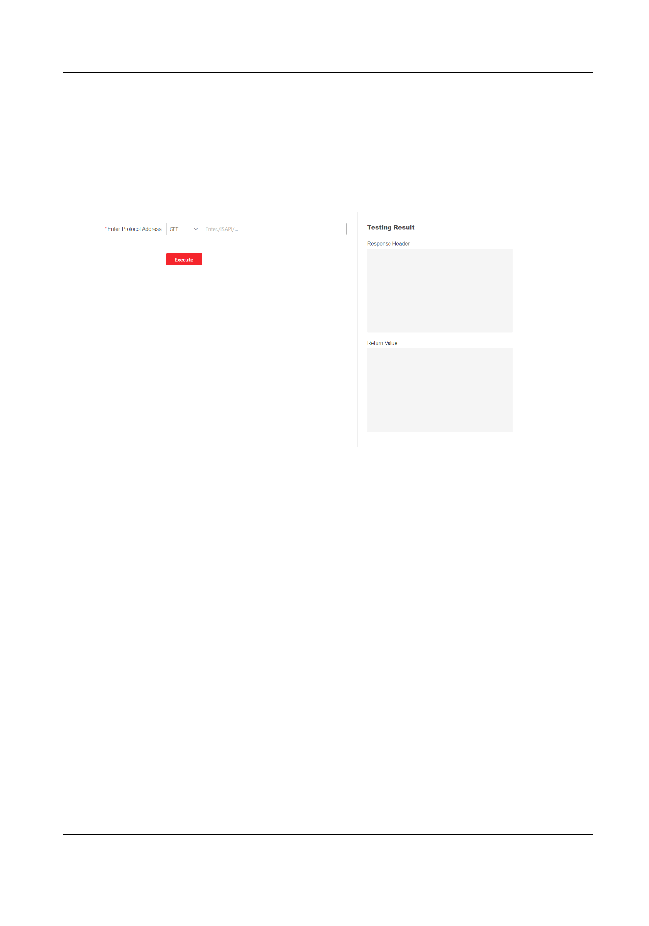
Test Protocol via PC Web
Select a protocol address, and enter the protocol to test. You can debug the device according to
the response header and returned value.
Go to System and Maintenance → Maintenance → Device Debugging → Protocol
Tesng .
Figure 7-21 Protocol
Tesng
Select a protocol address, and enter the protocol. Click Execute.
Debug the device according to the response header and returned value.
7.11.7 View Log via PC Web
You can search and view the device logs.
Go to System and Maintenance → Maintenance → Log .
Set the major and minor type of the log type. Set the start
me and end me for searching, and
click Search.
The results will be displayed below, which including the No.,
me, the major type the minor type,
the channel No., the local/remote user informaon, the remote host IP, etc.
7.11.8 Security Mode
Sengs
Set the security mode for logging in the client soware.
On the Device for Management page, click Maintenance and Security → Security → Security
Service .
DS-K1T502 Series Access Control Terminal User Manual
63
Select a security mode, and click Save.
Security Mode
High security level for user informaon vericaon when logging in the client soware.
Compable Mode
The user informaon vericaon is compable with the old client soware version when
logging in.
7.11.9 Cercate Management
It helps to manage the server/client cercates and CA cercate.
Note
The funcon is only supported by certain device models.
Create and Import Self-signed Cercate
Steps
1.
Go to System and Maintenance → Safe →
Cercate Management .
2.
In the Cercate Files area, select a Cercate Type from the drop-down list.
3.
Click Create.
4.
Input
cercate informaon.
5.
Click OK to save and install the cercate.
The created cercate is displayed in the Cercate Details area.
The cercate will be saved automacally.
6.
Download the cercate and save it to an asking le in the local computer.
7.
Send the asking le to a cercaon authority for signature.
8.
Import the signed
cercate.
1) Select a cercate type in the Import Key area, and select a cercate from the local, and
click Import.
2) Select a
cercate type in the Import Communicaon Cercate area, and select a cercate
from the local, and click Import.
Import Other Authorized
Cercate
If you already has an authorized cercate (not created by the device), you can import it to the
device directly.
Steps
1.
Go to System and Maintenance → Safe →
Cercate Management .
2.
In the Import Key and Import Communicaon Cercate areas, select cercate type and
upload
cercate.
DS-K1T502 Series Access Control Terminal User Manual
64

3.
Click Import.
Import CA Cercate
Before You Start
Prepare a CA cercate in advance.
Steps
1.
Go to System and Maintenance → Safe → Cercate Management .
2.
Create an ID in the Import CA
Cercate area.
Note
The input cercate ID cannot be the same as the exisng ones.
3.
Upload a cercate le from the local.
4.
Click Import.
DS-K1T502 Series Access Control Terminal User Manual
65
Chapter 8 Congure the Device via the Mobile
Browser
Set Network by TCP/IP
If device has connected to wired network, set the device IP address and enable the device hotspot
via the Web browser. For details, see the PC web browser's
sengs.
Enable the phone's Wi-Fi funcon and search the device hotspot.
Open the phone's browser and enter the device IP address to enter the mobile browser's sengs
page.
Set Network by Wi-Fi
If device has connected to Wi-Fi, set the device IP address and enable the device hotspot via the
Web browser. For details, see the PC web browser's
sengs.
Enable the phone's Wi-Fi funcon and search the device hotspot.
Note
The device and the phone should be in the same Wi-Fi environment, or you cannot visit the device
by the phone's browser.
Open the phone's browser and enter the device IP address to enter the mobile browser's sengs
page.
8.1 Login
You can login via mobile browser.
Note
●
Parts of the model supports Wi-Fi sengs.
●
Make sure the device is acvated.
●
Make sure the device and the mobile phone are in the same Wi-Fi.
Enter the device IP address in the address bar of the mobile browser and press Enter to enter the
login page.
Enter the device user name and the password. Tap Login.
8.2 Forget Password
If you forget the password when logging in, you can change the password by security quesons.
DS-K1T502 Series Access Control Terminal User Manual
66
Steps
1.
On the login page, tap Forget Password.
2.
Select Vericaon Mode.
Security
Queson Vericaon
If you have set security quesons on the device or mobile web, you can enter the answers to
reset the password. Tap Security
Queson Vericaon, and tap Next.
3.
Enter the answer of the security queson, and tap Next.
4.
Enter the new password and conrm it.
5.
Tap Next.
8.3 Account Security Sengs
Change the reserved phone No. and when you forgot the password, you can use the phone No. to
change the login password.
Steps
Note
Only the device and the phone are in the same LAN, can you see the sengs.
1.
Tap → User Management → → Account Security Sengs.
2.
Change the reserved phone No. When you forget your login password, you can enter the phone
No. to change the password.
3.
Tap Save.
8.4 Home
You can view the door status, enter the conguraon page via shortcut entry, view the network
status, and view basic informaon.
Door Status
You can view the door status. And control the door status.
Shortcut Entry
Tap the conguraon funcon name and enter the page.
Network Status
You can view the network connecon status.
Basic
Informaon
You can view the device model, serial No., and version, or enter the basic informaon page.
DS-K1T502 Series Access Control Terminal User Manual
67
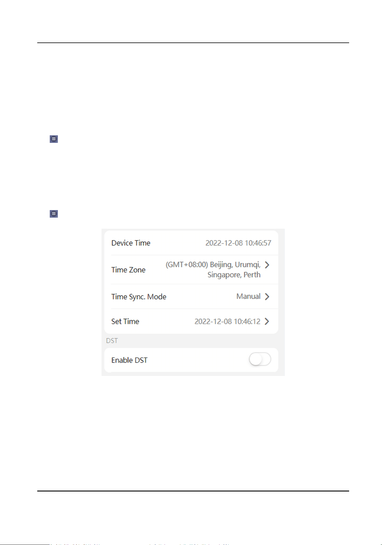
8.5 Conguraon
8.5.1 View Device Informaon
View the device name, language, model, serial No., version, IO input number, local RS-485 number,
number of alarm output, register number, Mac address, and device capacity, etc.
Tap
→ System Sengs → Basic Informaon to enter the conguraon page.
You can view the device name, language, model, serial No., version, IO input number, local RS-485
number, number of alarm output, register number, Mac address, and device capacity, etc.
8.5.2 Time
Sengs
Set the me zone, me sync. mode, and displayed me.
Tap → System Sengs → Time Sengs to enter the sengs page.
Figure 8-1 Time Sengs
Tap Save to save the sengs.
Time Zone
Select the me zone where the device is located from the drop-down list.
Time Sync. Mode
Manual
DS-K1T502 Series Access Control Terminal User Manual
68
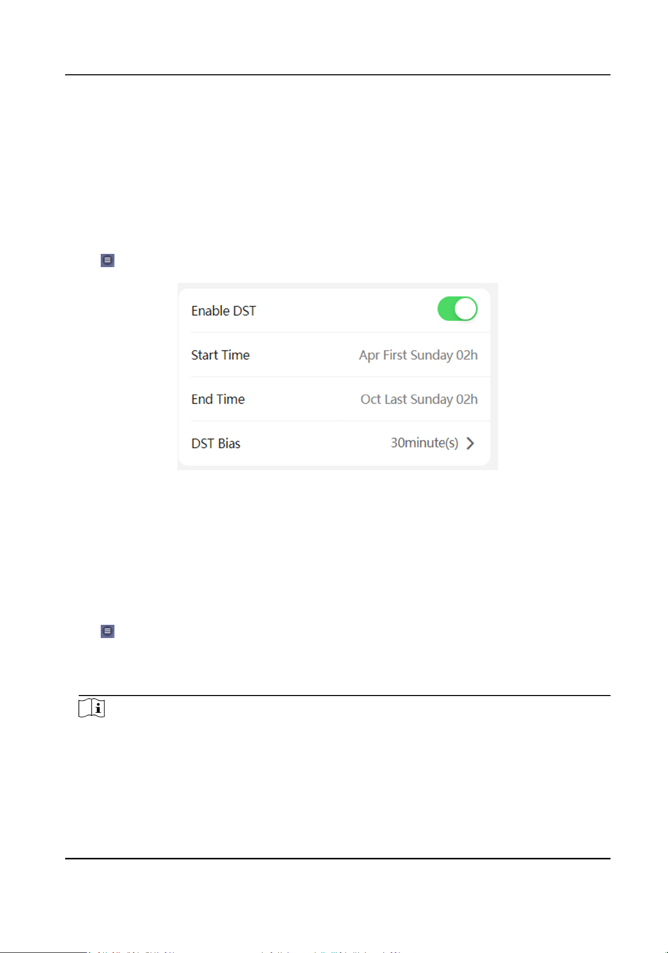
By default, the device me should be synchronized manually. You can set the device me
manually.
NTP
Set the NTP server's IP address, port No., and interval.
8.5.3 Set DST
Steps
1.
Tap → System Sengs → Time Sengs , to enter the sengs page.
Figure 8-2 DST
2.
Tap Enable DST.
3.
Set the start me, end me, and DST bias.
4.
Tap Save.
8.5.4 User Management
Steps
1.
Tap
→ User Management → User Management → admin to enter the seng page.
2.
Enter the old password and create a new password.
3.
Conrm the new password.
4.
Tap Save.
Note
The password strength of the device can be automacally checked. We highly recommend you
change the password of your own choosing (using 8-16 characters, including at least two kinds
of following categories: upper case leers, lower case leers, numbers, and special characters)
in order to increase the security of your product. And we recommend you change your password
DS-K1T502 Series Access Control Terminal User Manual
69

regularly, especially in the high security system, changing the password monthly or weekly can
beer protect your product.
8.5.5 Network
可配置设设有设网设参数、Wi-Fi 参数和设设设点参数。
Wired Network
Set wired network.
Tap → Communicaon Sengs → Wired Network to enter the conguraon page.
DHCP
If you disable the
funcon, you should set the IPv4 address, IPv4 subnet mask, IPv4 default
gateway, IPv6 mode, IPv6 address, IPv6 subnet prex length, IPv6 default gateway, Mac address,
and MTU, Mac address, MTU.
If you enable the
funcon, the system will allocate the IPv4 address, IPv4 subnet mask, the IPv4
default gateway, IPv6 mode, IPv6 address, IPv6 subnet prex length, and IPv6 default gateway
automacally.
DNS Server
Set the preferred DNS server and the Alternate DNS server according to your actual need.
Set Wi-Fi
Sengs
Set the Wi-Fi parameters of the device.
Before You Start
Aer the device is added to the App, you can enabled the device Wi-Fi funcon. And then you can
set eh Wi-Fi parameters in the mobile web.
Steps
1.
On the home page, tap → Communicaon Sengs → Wi-Fi.
2.
Enable Wi-Fi.
3.
Select a Wi-Fi in the list and enter the password to connect.
4.
Oponal: Add a Wi-Fi.
1) Slide the page to the end and tap Add Network.
2) Enter Wi-Fi Name, and select the Wi-Fi’s
Encrypon Type.
3) Tap OK.
5.
Oponal: Set WLAN.
1) Set the connected Wi-Fi’s name, and view the network details.
2) Tap WLAN
Sengs.
3) Set the WLAN parameters.
DS-K1T502 Series Access Control Terminal User Manual
70
Enable DHCP
Enable DHCP to Auto DNS, the device will allocate the IP and DNS automacally.
Disable DHCP
Manually set the IP and DNS server.
4) Tap Save.
Result
Aer Wi-Fi and WLAN sengs, you can enter the WLAN IP address in the mobile browser to login
the device.
Set Device Hotspot
Set the device hotspot, and mobile phone can connect to the device to enter the mobile browser.
Steps
1.
Tap → Communicaon Sengs → Device Hotspot .
2.
You can enable device hotspot and view the hotspot name.
Note
By default, the hotspot name is the AP_Device Serial No.
3.
Tap Save.
Set Port Parameters
You can set the HTTP and HTTPS according to actual needs when accessing the device via network.
Tap → Network Service → HTTP(S) , to enter the seng page.
HTTP
It refers to the port through which the browser accesses the device. For example, when the
HTTP Port is
modied to 81, you need to enter hp://192.0.0.65:81 in the browser for login.
HTTPS
Set the HTTPS for accessing the browser. Cercate is required when accessing.
Plaorm
Access
Plaorm access provides you an opon to manage the devices via plaorm.
Steps
1.
Tap → Device Access → Hik-Connect to enter the sengs page.
DS-K1T502 Series Access Control Terminal User Manual
71
Note
Hik-Connect is an applicaon for mobile devices. With the App, you can view live image of the
device, receive alarm nocaon and so on.
2.
Check Enable to enable the funcon.
3.
You can enable Custom to enter the server address.
Note
●
6 to 12 leers (a to z, A to Z) or numbers (0 to 9), case sensive. You are recommended to use
a combinaon of no less than 8 leers or numbers.
●
The vericaon code cannot be 123456 or abcdef (case non-sensive0).
4.
You can view Register Status and Binding Status.
5.
You can tap Bind An Account → View QR Code , scan the QR code to bind an acount.
6.
Tap Save to enable the
sengs.
Set ISUP Parameters
Set the ISUP parameters for accessing device via ISUP protocol.
Steps
Note
The funcon should be supported by the device.
1.
Tap → Device Access → ISUP to enter the sengs page.
2.
Enable ISUP.
3.
Set the ISUP version, server Address, port, device ID and
encrypon key.
Note
If you select 5.0 as the version, you should set the encrypon key as well.
4.
Tap Save to save the sengs.
VoIP
Sengs
Tap → Device Access → VoIP to enter the sengs page.
Tap to Enable VoIP Gateway.
Set VoIP parameters and tap Save to save the parameters.
8.5.6 User Management
You can add, edit, delete, and search users via mobile Web browser.
DS-K1T502 Series Access Control Terminal User Manual
72
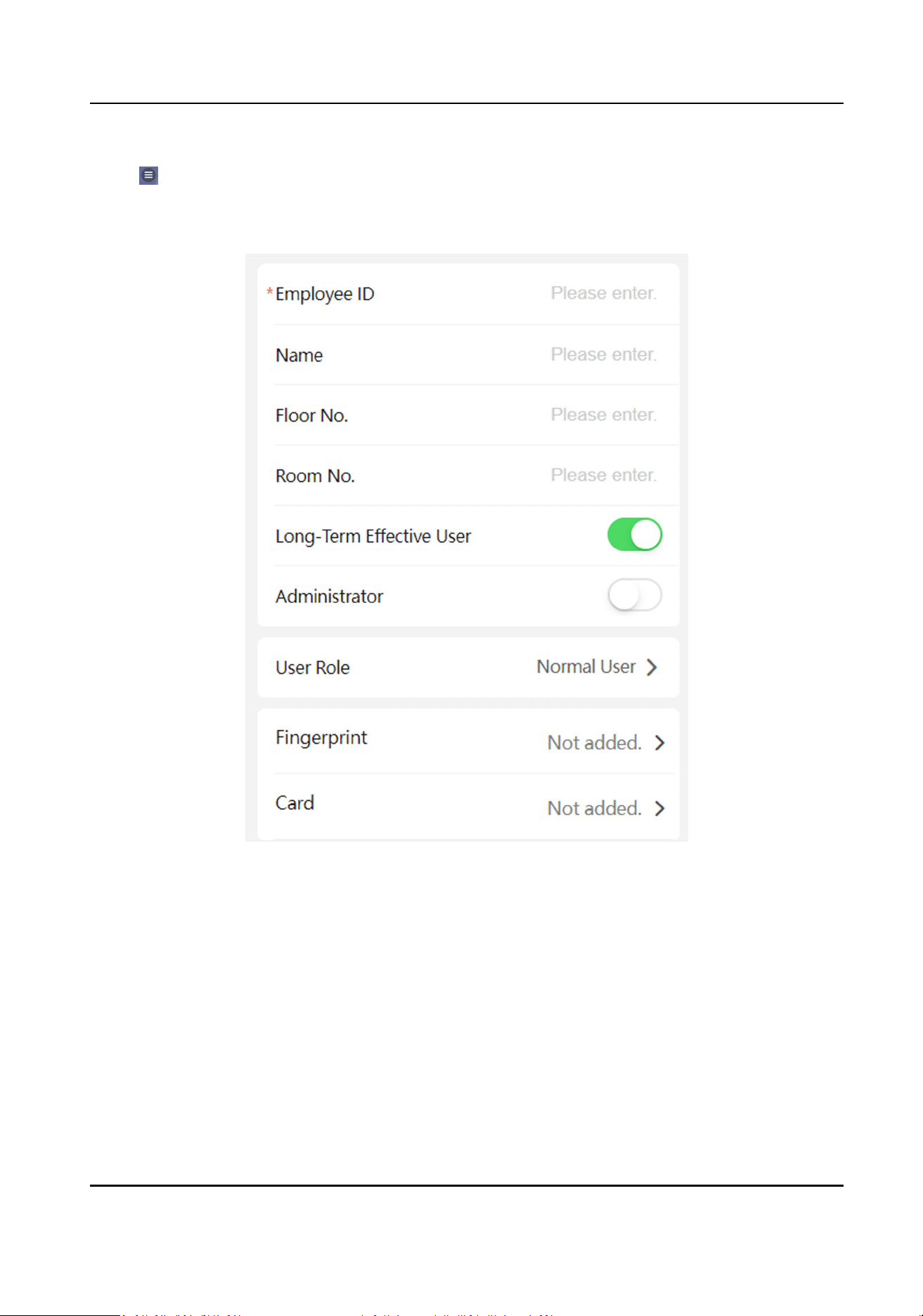
Steps
1.
Tap → Person Management to enter the sengs page.
2.
Add user.
1) Tap+.
Figure 8-3 Add User
2) Set the following parameters.
Employee ID
Enter the employee ID. The Employee ID cannot be 0 or exceed 32 characters. It can be a
combinaon of uppercase, lowercase leers and numbers.
Name
Enter your name. The name supports numbers, uppercase and lowercase English, and
characters. The name is recommended to be within 32 characters.
Floor No./Room No.
Enter the
oor No./room No.
DS-K1T502 Series Access Control Terminal User Manual
73

Long-Term Eecve
Set the user permission as long-term eecve.
Start Date/End Date
Set Start Date and End Date of user permission.
Administrator
If the user needs to be set as administrator, you can enable Administrator.
User Role
Select your user role.
Fingerprint
Add
ngerprint. Tap Fingerprint, then tap +, and add ngerprint via the ngerprint module.
Card
Add card. Tap Add Card. Enter the Card No., or present the card on the device and tap
Read, and select the Property. Tap Save to add the card.
Password
Note
●
Before conguring passwords, it is necessary to clarify whether the password is device-
set personal PIN or a plaorm-applied personal PIN. If it is a device-set personal PIN, it
can be created and edited on Web and cannot be created and edited on the plaorm; If
it is a
plaorm-applied personal PIN, it needs to be congured on the plaorm and
cannot be edited on the Web.
●
Make sure Password Mode is selected as Device Password.
Tap
Person Management → Add to enter the Add Person page.
Enter the password.
3) Tap Save.
3.
Tap the user that needs to be edited in the user list to edit the
informaon.
4.
Tap the user that needs to be deleted in the user list, and tap to delete the user.
5.
You can search the user by entering the employee ID or name in the search bar.
8.5.7 Event Search
Tap → Event Search.
Enter the search
condions, including the employee ID, the name, the card No., the start me, and
the end me, and tap Search.
Note
Support searching for names within 32 digits.
The result will display in the list.
DS-K1T502 Series Access Control Terminal User Manual
74

8.5.8 Audio Sengs
You can enable or adjust the audio.
Tap
→ Audio.
Enable Enable Voice Prompt according to actual needs. The device will prompt voice instrucons.
You can also adjust the audio volume.
You can enable Audio
Equalizaon, the device will auto adjust frequency by audio algorithm to
improve audio quality and equalize audio
eect.
Tap Save.
8.5.9 Access Control
Sengs
Set Authencaon Parameters
Set Authencaon Parameters.
Steps
1.
Tap → Access Control → Authencaon Sengs .
DS-K1T502 Series Access Control Terminal User Manual
75
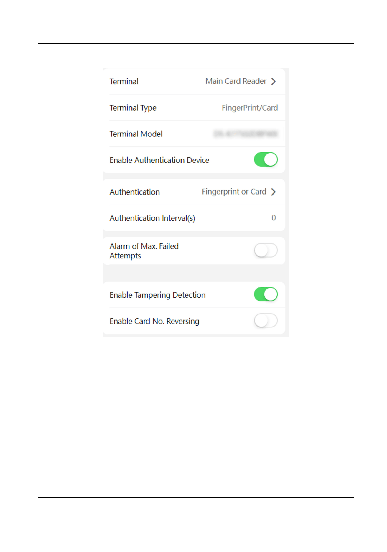
Figure 8-4 Authencaon Sengs
2.
Tap Save.
Terminal
Main Card Reader
You can
congure the device card reader's parameters. If you select main card reader, you
need to congure the following parameters: Terminal Type, Terminal Model, Enable Card
Reader,
Authencaon, Recognion Interval (s), Minimum Card Swiping Interval (s),
Max. Authencaon Failed Aempts Alarm/Alarm of Max. Failed Aempts, Enable
Tampering
Detecon and Enable Card No. Reversing.
Card Reader Type
Get card reader type.
DS-K1T502 Series Access Control Terminal User Manual
76

Card Reader Descripon
Get card reader descripon. It is read-only.
Enable Card Reader
Enable the card reader's funcon.
Authencaon
Select an authencaon mode according to your actual needs from the drop-down list.
Authencaon Interval
You can set the
authencaon interval of the same person when authencang. The same
person can only authencate once in the congured interval. A second authencaon will be
failed.
Max. Authencaon Failed Aempts Alarm/Alarm of Max. Failed Aempts
Enable to report alarm when the card reading aempts reach the set value.
Enable Tampering Detecon
Enable the an-tamper detecon for the card reader.
Enable Card No. Reversing
The card No. will be in reverse sequence aer enabling the funcon.
QR Code
Enable the funcon and the user can use QR code to open the door.
Note
●
Disable the IR light if enabling the QR code funcon. For details, see . The picture in low
illuminaon environment may be aected due to disabling the IR light.
●
Set QR code funcon via HCC or HCEC, you should select compable to 1.0 or 2.0. 2.0 is
recommended.
Set Door Parameter
Set door parameters, including door name, open duraon, exit buon type, door remain open
duraon with rst person, door open meout alarm, door contact, extended open duraon, duress
code, super password, and dismiss code.
Tap
→ Access Control → Door Parameters.
Aer sengs, tap Save.
Name
Create a name for the door.
Open
Duraon
Set the door unlocking duraon aer swiping the card.
Exit Buon Type
DS-K1T502 Series Access Control Terminal User Manual
77
You can set the exit buon as Remain Open or Remain Closed according to your actual needs.
By default, it is Remain Open.
Door Remain Open Duraon with First Person
Set the door open duraon when rst person is in. Aer the rst person is authorized, it allows
mulple persons access the door or other authencaon acons.
Door Opening Timeout Alarm Threshold
If the door is not closed
aer reaching the lock acon me, the access control point will sound
an alarm. When set as 0, alarm will not be enabled.
Door Contact
You can set the door contact as Remain Open or Remain Closed according to your actual needs.
By default, it is Remain Closed.
Extended Open Duraon
The door contact can be enabled with appropriate delay aer person with extended access
needs swipes her/his card.
Duress Code
The door can open by
inpung the duress code when there is duress. At the same me, the
client can report the duress event.
Super Password
Administrator or designated person can enter the super password to open the door.
Dismiss Code
Create a dismiss code. When an alarm is triggered, you can enter the dismiss code to dismiss
the alarm.
Note
Duress code and super password can’t be duplicated, usually consisng of 4 to 8 digits.
Access Control and Elevator Control
Steps
1.
Tap
→ Access Control → Elevator Control Parameters.
2.
Enable Elevator Control, and set Negave Floor Capacity, Main Elevator Controller Model, and
Interface Type.
Note
●
Only main door staon supports elevator control.
●
If you select Network Interface as interface type, you should set server address, port, user,
and password.
3.
Tap Save.
DS-K1T502 Series Access Control Terminal User Manual
78
Terminal Parameters
You can set terminal parameters for accessing.
Tap
→ Access Control → Terminal Parameters .
You can set Working Mode as Access Control Mode. The access control mode is the device normal
mode. You should authencate your credenal for accessing.
Tap Save to save the
sengs aer the conguraon.
Set RS-485 Parameters
You can set the RS-485 parameters including the peripheral, address, baud rate, etc.
Tap → Access Control → RS-485 .
Tap Save to save the sengs aer the conguraon.
Peripheral Type
Select a peripheral from the drop-down list according the actual situaon. You can select from
Card Reader, Extension Module, or Access Controller.
Note
Aer the peripheral is changed and saved, the device will reboot automacally.
RS-485 Protocol
Private
The device can connect with the third party device via RS-485.
OSDP
Standard RS-485 protocol.
RS-485 Address
Set the RS-485 Address according to your actual needs.
Note
If you select Access Controller: If connect the device to a terminal via the RS-485 interface, set
the RS-485 address as 2. If you connect the device to a controller, set the RS-485 address
according to the door No.
Baud Rate
The baud rate when the devices are communicang via the RS-485 protocol.
Data Bit
The data bit when the devices are communicang via the RS-485 protocol.
Stop Bit
DS-K1T502 Series Access Control Terminal User Manual
79

The stop bit when the devices are communicang via the RS-485 protocol.
Parity/Flow Ctrl/Communicaon Mode
Enabled by default.
Output Type
Set the output type according to your actual needs.
Set Card Security
Congure cards for the device.
Tap
→ Access Control → Card Security .
DS-K1T502 Series Access Control Terminal User Manual
80
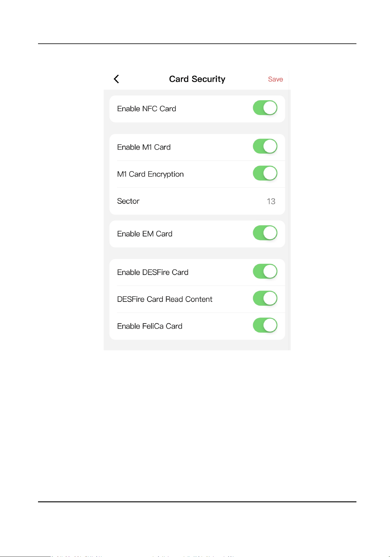
Figure 8-5 Card Security
Congure card parameters, and click Save.
Enable NFC Card
In order to prevent the mobile phone from geng the data of the access control, you can
disable NFC card to increase the security level of the data.
Enable M1 Card
Enable M1 card and
authencang by presenng M1 card is available.
M1 Card Encrypon
M1 card encrypon can improve the security level of authencaon.
Sector
DS-K1T502 Series Access Control Terminal User Manual
81

Enable the funcon and set the encrypon sector.
Note
It is recommended to encrypt sector 13.
Enable EM Card
Enable EM card and authencang by presenng EM card is available.
Note
If the peripheral card reader supports presenng EM card, the funcon is also supported to
enable/disable the EM card funcon
Enable DESFire Card
The device can read the data from DESFire card when enabling the DESFire card funcon.
DESFire Card Read Content
Aer enable the DESFire card content reading funcon, the device can read the DESFire card
content.
Enable FeliCa Card
The device can read the data from FeliCa card when enabling the FeliCa card funcon.
8.5.10 Call
Sengs
Set Device No. via Mobile Web
The device can be used as access control device, door staon, or outer door staon. You can set
the device number for video intercom.
Tap
→ Intercom → Device ID Sengs.
Tap Save.
If select the device type as Door
Staon or Access Control Device, you can set the device period
No., building No., unit No., oor No., and door staon No.
Device Type
The device can used as door
staon. You can select other device type from the drop-down list.
Community No.
Enter the device community No. (period No.)
Building No.
Enter the device building No.
No.
Customize device No.
DS-K1T502 Series Access Control Terminal User Manual
82
Note
●
If the device type is Door Staon or Access Control Device, the No. should be between 0 and
99.
●
Aer changing the device type or No., you should reboot the device to take eect.
Unit No.
Enter the device unit No.
Floor No.
Enter the device oor No.
If select the device type as Outer Door Staon , you can set the device period No., and outer door
staon No.
Device Type
The device can used as out door staon. You can select other device type from the drop-down
list.
Community No.
Enter the device community No. (period No.)
No.
Customize device No.
Note
●
If the device type is Outer Door Staon, the No. should be between 1 and 99.
●
Aer changing the device type or No., you should reboot the device to take eect.
Note
Aer changing the device type or No., you should reboot the device to take eect.
Session Sengs
You can set the registraon password, main staon IP and private server IP, and you can enable
protocol 1.0 according to your actual needs.
Tap
→ Intercom → Session Sengs.
Registraon Password
Set the registraon password of the main staon for communicaon. Set the registraon
password of the main staon for communicaon.
Main Staon IP
Enter the main staon’s IP address that used for communicaon.
Private Server IP
DS-K1T502 Series Access Control Terminal User Manual
83

Refers to the SIP server IP. Enter the main staon’s IP address that used for communicaon. At
this me the main staon is used as a SIP server. Other intercom devices should registered to
this server address to realize communicaon.
Enable Protocol 1.0
If enabled, the door staon can be registered to the main staon by old protocol version. If
disabled, the door staon can be registered to the main staon by new protocol version.
Aer conguraon, you can achieve communicaon between access control devices and video
intercom door
staon, indoor staon, main staon, plaorms, etc.
Click Save.
Call
Sengs
you can set Max. communicaon duraon between the main staon and other devices.
Tap
→ Intercom → Call Sengs.
Max. Communicaon Time
The Maximum communicaon me when the main staon and the other devices are in the call.
When the
communicaon me exceeds the congured me, the communicaon will stop. The
Max. communicaon me range is 90 s to 120 s.
Number
Sengs
Set SIP number for the room. The rooms can communicate with each other via SIP number.
Steps
1.
Tap → Intercom → Number Sengs.
2.
Enter Room No. and SIP Number1.
3.
Tap Save.
4.
Oponal: Tap the congured room No., edit or tap +Add to add another SIP number.
5.
Oponal: Tap Delete to delete room number.
Press
Buon to Call via Mobile Web
You can press the buon to call.
Steps
1.
Tap → Intercom → Press Buon to Call.
2.
Tap 1 to enter the page.
DS-K1T502 Series Access Control Terminal User Manual
84

Note
●
When you check Call Specied Indoor Staon, you should set the linked room’s No.
●
By default, you can press the buon to call indoor staon, and hold the buon to call center.
3.
Select the item that the buon linked to. When select Call Specied Indoor Staon, you should
set the room’s No.
4.
Tap Save.
8.5.11 Set Privacy Parameters via Mobile Web
Set picture uploading and storage parameters.
Tap → Privacy Sengs.
Picture Uploading and Storage
You can enable Save Pictures
Aer Linked Capture or Upload Picture Aer Linked Capture. The
captured pictures will upload or save to the plaorm.
Tap Save.
8.5.12 Password Mode
Before conguring passwords, it is necessary to clarify whether the password is a device-set
personal PIN or a
plaorm-applied personal PIN. If it is a device-set personal PIN, it can be created
or edited on the device or on the web, and cannot be set on other plaorms; If it is a plaorm-
applied
personal PIN, it can be created or edited on the plaorm, and issued to the device before it
can be used. It cannot be set on the device or on the web.
Steps
1.
Tap → Conguraon → Security → Password Mode
Device-Set Personal PIN
It can be created or edited on the device or on the web, and cannot be set on other
plaorms.
Plaorm-Applied Personal PIN
It can be created or edited on the plaorm, and issued to the device before it can be used. It
cannot be set on the device or on the web.
2.
Tap Save.
8.5.13 Upgrade and Maintenance
Restart device, restore device parameters, and upgrade device version.
DS-K1T502 Series Access Control Terminal User Manual
85
Restart Device
Tap → Restart Device .
Tap Restart to restart the device.
Upgrade
Tap → Upgrade .
Tap Upgrade to upgrade the device.
Note
Do not power o during the upgrading.
Restore Parameters
Tap → Default .
Restore to Default Sengs
The device will restore to the default sengs, except for the device IP address and the user
informaon.
Restore to Factory Sengs
All parameters will be restored to the factory sengs. You should acvate the device before
usage.
8.5.14 View User Document
View the user document.
Note
Only when you enter the mobile web by IP address, can you view the user document. Login by hot
spot does not support the funcon.
Tap to enter the page.
Tap View Online Document to view the user manual.
8.5.15 Open Source
Soware Licenses
You can view the open source soware licenses.
Tap
to enter the page.
Tap Open Source Soware Licenses.
DS-K1T502 Series Access Control Terminal User Manual
86

8.5.16 Log Out of Mobile Web
Log out of the conguraon page on the mobile web.
On the home page, tap
→ Log Out , and tap OK to log out of the web.
If you need to go to the conguraon page, please enter user name and password again.
DS-K1T502 Series Access Control Terminal User Manual
87

Chapter 9 Other Plaorms to Congure
You can also congure the device via iVMS-4200 Client Soware or HikCentral Access Control. For
details, see the
plaorms' user manual.
iVMS-4200 Client Soware
Click/tap the link to view the client soware's user manual.
hp://enpinfodata.hikvision.com/analysisQR/showQR/ca930247
HikCentral Access Control (HCAC)
Click/tap the link to view the HCAC's user manual.
hp://enpinfodata.hikvision.com/analysisQR/showQR/f2f6cf42
DS-K1T502 Series Access Control Terminal User Manual
88
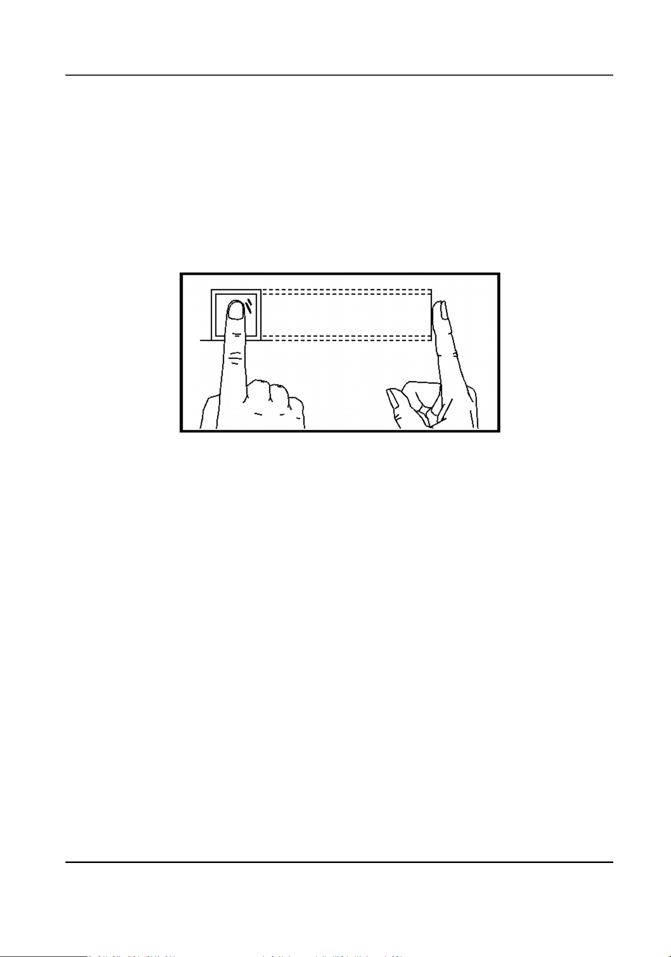
Appendix A. Tips for Scanning Fingerprint
Recommended Finger
Forenger, middle nger or the third nger.
Correct Scanning
The gure displayed below is the correct way to scan your nger:
You should press your nger on the scanner horizontally. The center of your scanned nger should
align with the scanner center.
Incorrect Scanning
The gures of scanning ngerprint displayed below are incorrect:
DS-K1T502 Series Access Control Terminal User Manual
89
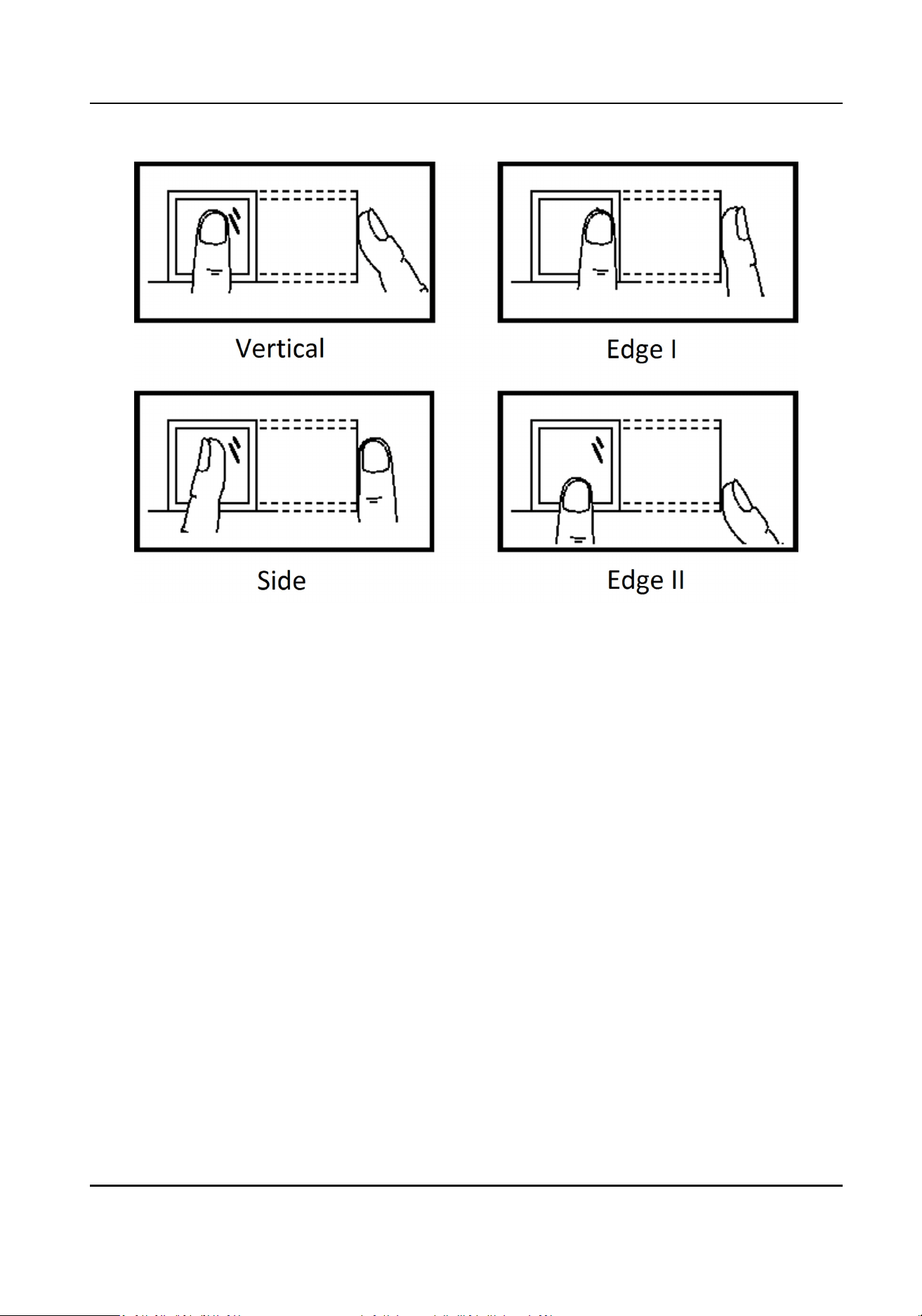
Environment
The scanner should avoid direct sun light, high temperature, humid condions and rain.
When it is dry, the scanner may not recognize your
ngerprint successfully. You can blow your
nger and scan again.
Others
If your ngerprint is shallow, or it is hard to scan your ngerprint, we recommend you to use other
authencaon methods.
If you have injuries on the scanned nger, the scanner may not recognize. You can change another
nger and try again.
DS-K1T502 Series Access Control Terminal User Manual
90
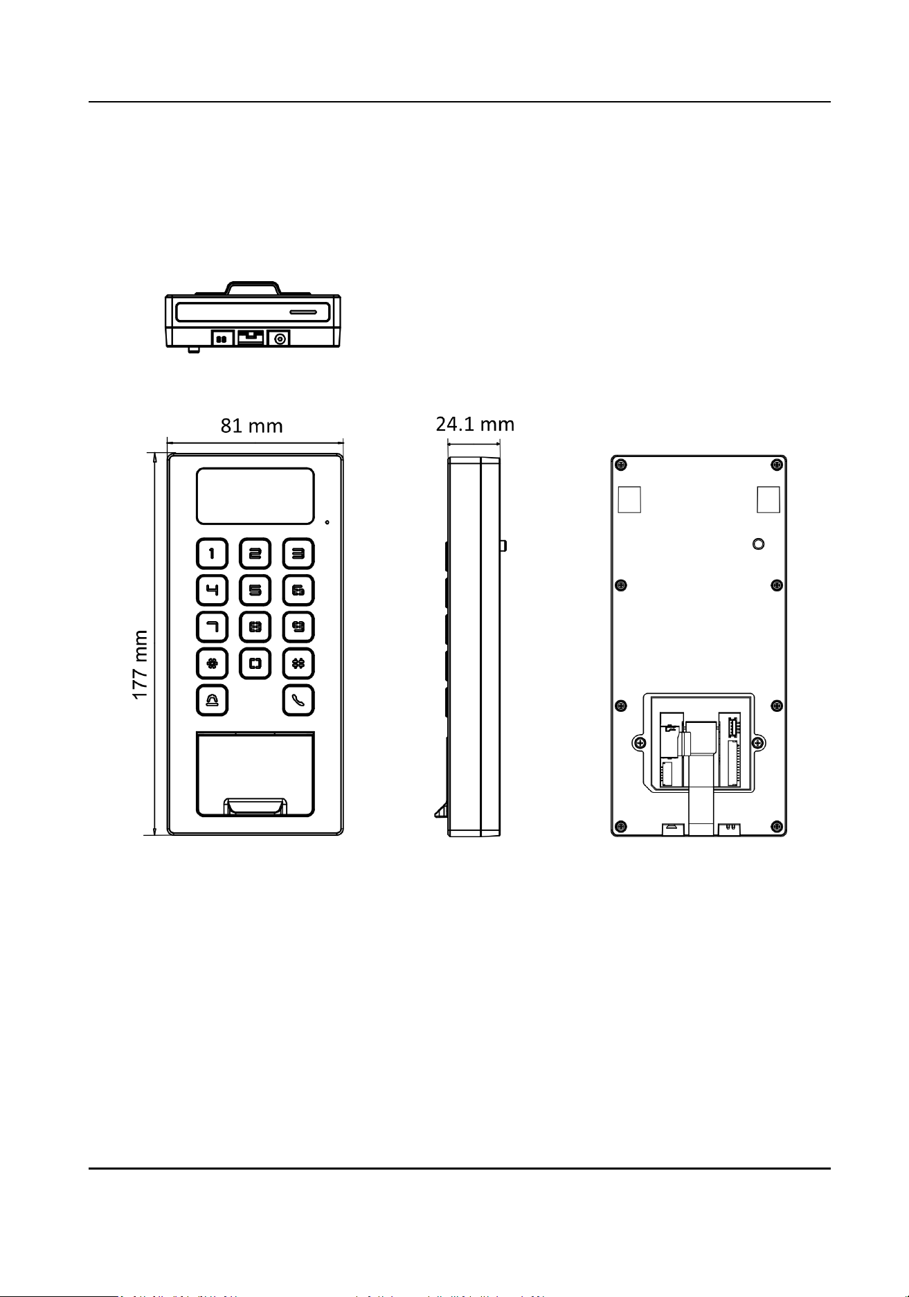
Appendix B. Dimension
Dimension of Device
DS-K1T502 Series Access Control Terminal User Manual
91

UD29355B-D