Installation and Reference Guide
57750-001
Rev 01
English
SMART HOME PLATFORM

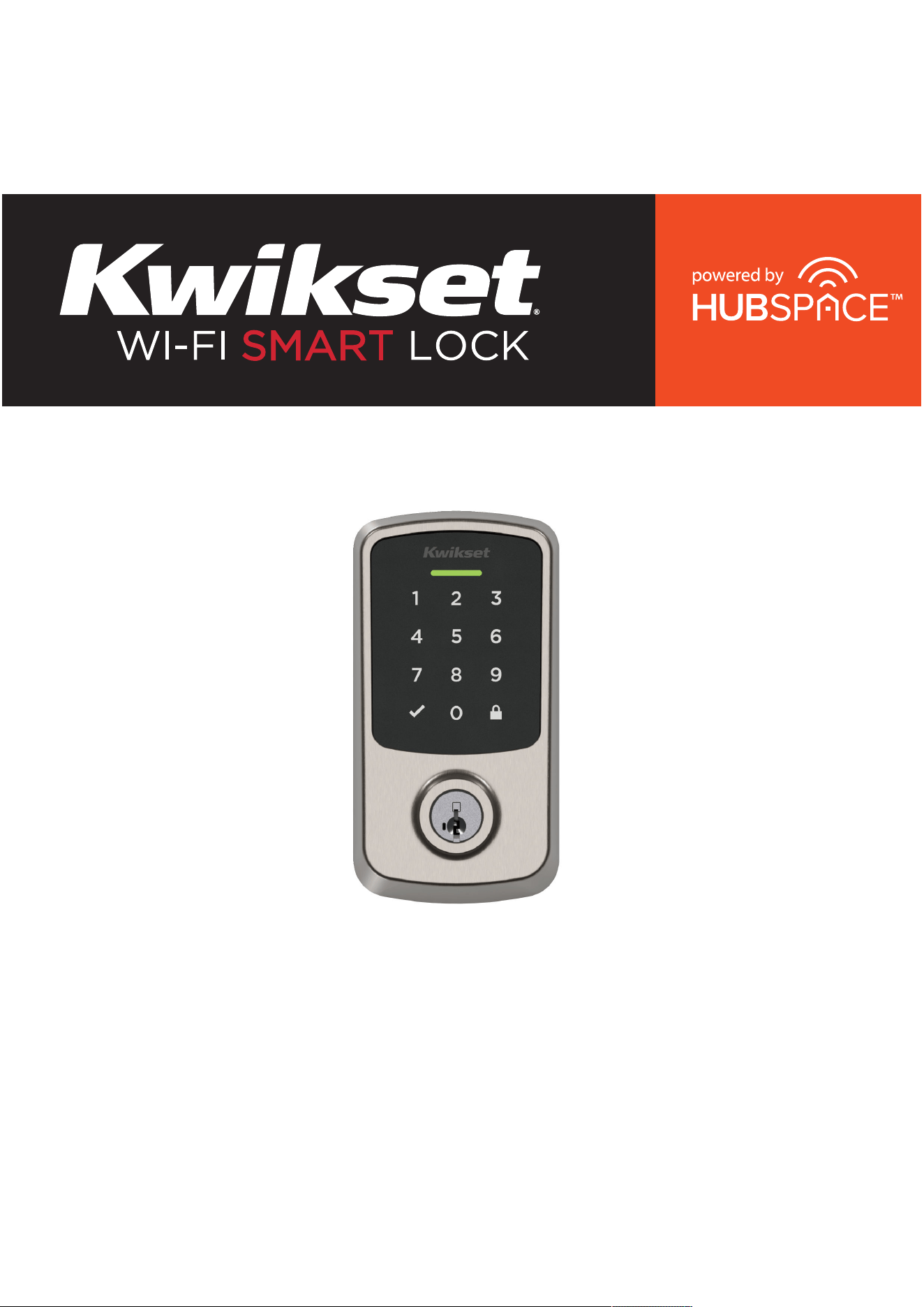
Welcome to the Kwikset family!
This guide will get you up and running with
your new Wi-Fi Smart Lock.
If you have any issues, please visit our
support center: kwikset.com/support
or call us at 1-800-327-5625.
Getting started
For an interactive version of this installation guide,
scan here or go to kwikset.com/hubspace-install
1
UPDATE NEEDED

Parts in the box ..............................................4
Required tools ................................................5
Installation ........................................................7
Reference guide ............................................18
Table of contents
3
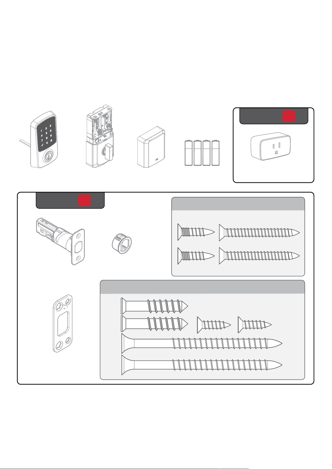
Parts in the box
Exterior
Assembly
Interior
Assembly
Interior
Cover
4
Latch
Collar
Strike
1
Pack
03809
52531
Batteries
2
Pack
Smart Plug
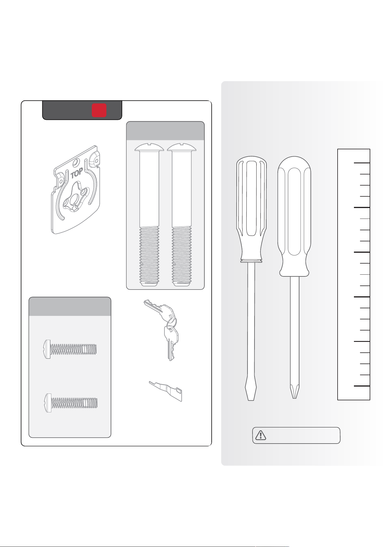
Required
tools
Phillips head
screwdriver
No electric drills
5
Ruler
Flat head
screwdriver
Mounting
plate
Keys
3
Pack
52367
SmartKey™
tool
52502

Installation
7
If drilling a new door, use
the supplied template and
instructions available at:
kwikset.com/doorprep
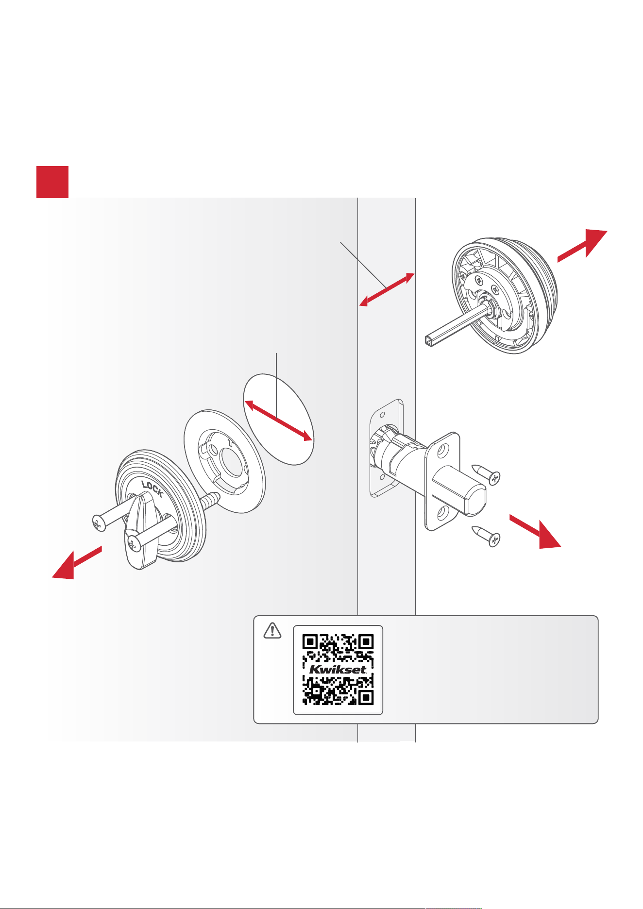
Remove your existing deadbolt
!
1-3/8” to 2-1/4”
(35mm - 57mm)
1-1/2 or 2-1/8”
(38mm to 54mm)
Your new lock will
only support a door
thickness of 1-3/8”
to 2-1/4” (35mm to
57mm) and a door
bore hole diameter
of 1-1/2“ or 2-1/8”
(38mm or 54mm).
8
1
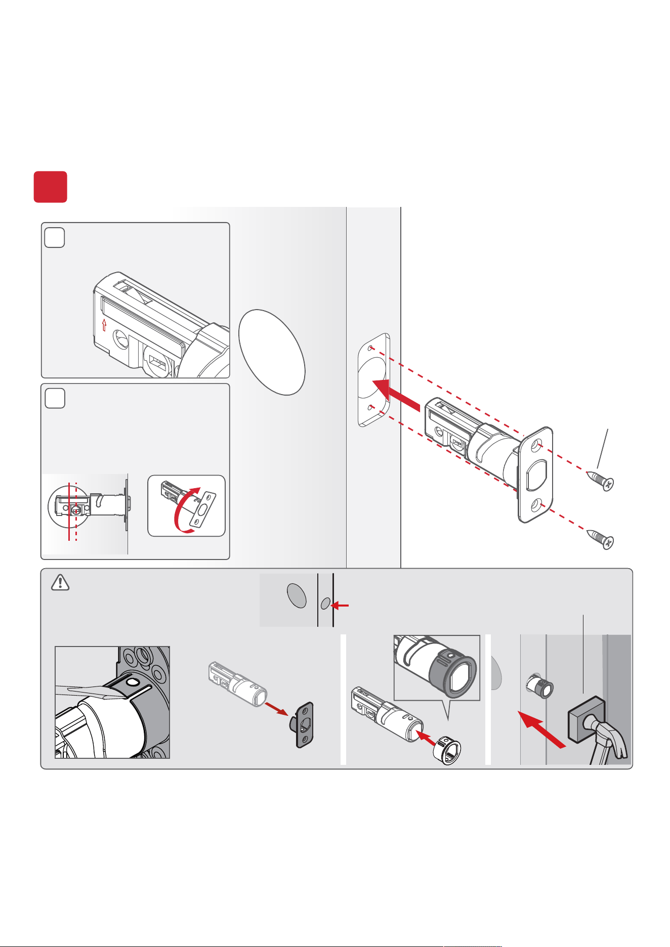
Install the latch
B
UP
A
*Use the longer
screws if the holes
are worn out.
You will have two
extra screws.
If the rectangle shaped
hole is not centered in
the door hole, rotate
the latch face to extend
the latch.
03809*
(2X)
If your door is not chiseled,
install the drive-in collar.
[OUTSIDE]
UP is on top.
wood block
Loosen faceplate with
flathead screwdriver.
DOOR
JAMB
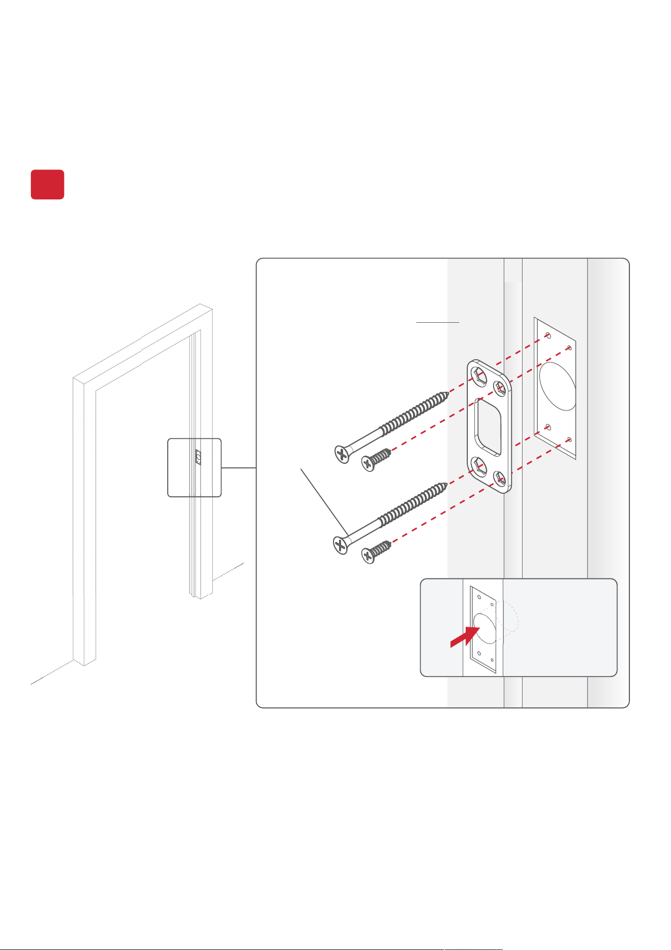
*Install the longer
screws closest to
the door jamb.
52531*
(4X)
2
Install the strike
1" (25 mm)
hole depth
9
10
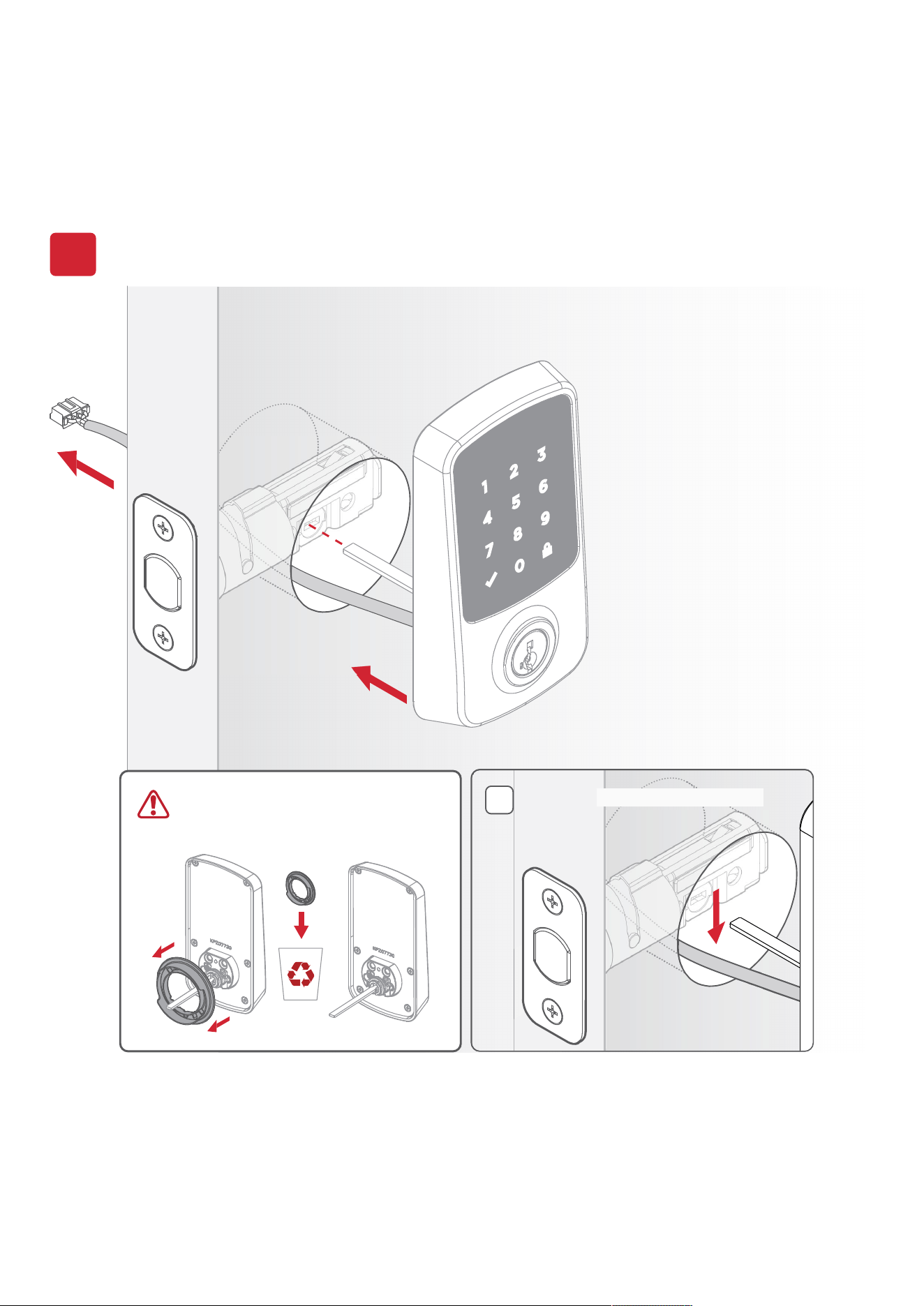
Install the exterior assembly
3
[OUTSIDE]
Cable goes under the latch.
A
Remove adapter ring if bore
hole measures 1-1/2” (38mm)
diameter.
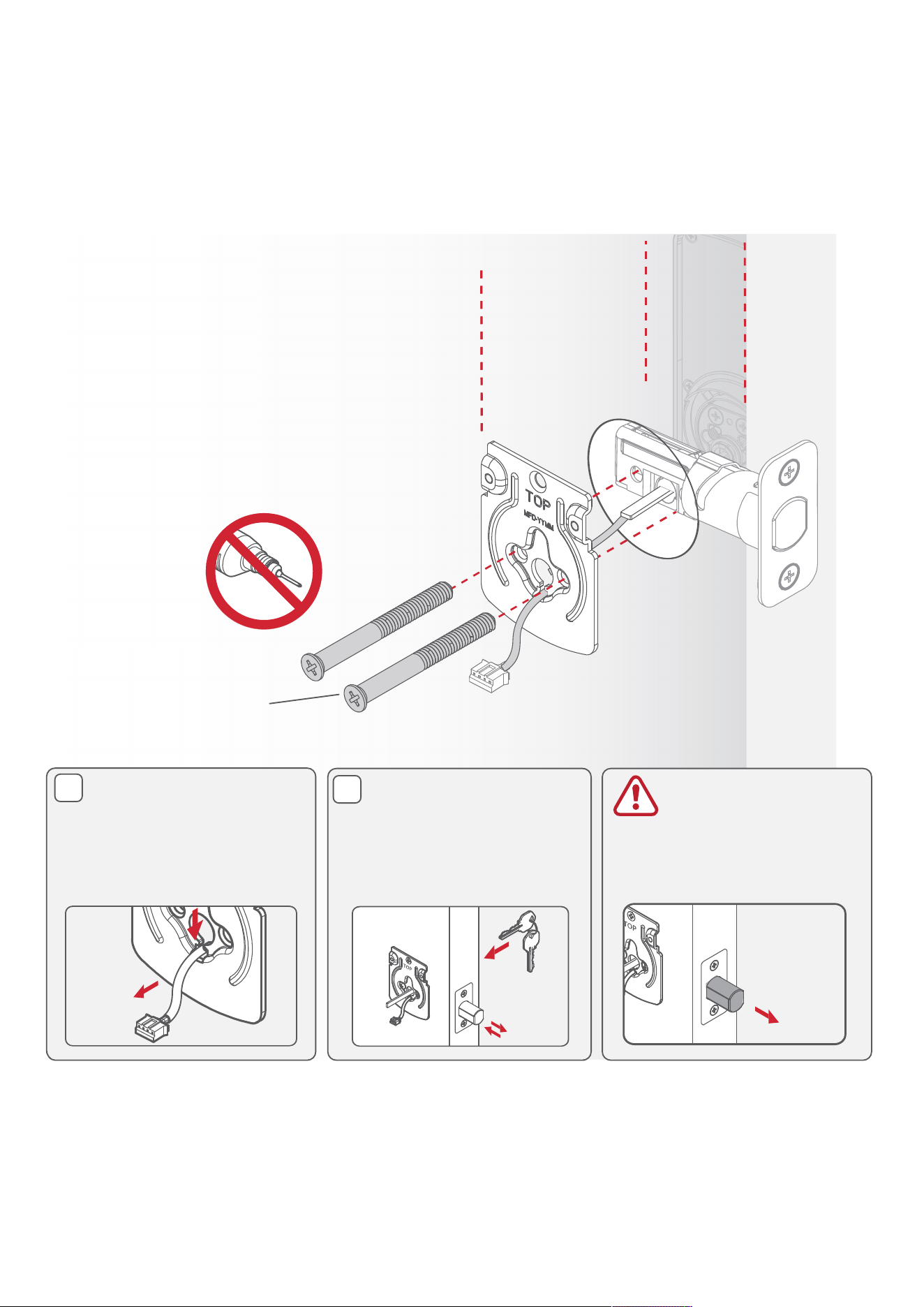
11
[INSIDE]
Tighten the screws evenly.
(2X)
[INSIDE]
Tighten the screws evenly.
DO NOT over-tighten.
Keep parallel to
the door edge
52367
B
C
Route the cable through
the center hole of the
mounting plate, then
push the cable down
into the bottom hole.
Insert the key and test
the latch. If the latch
does not extend or
retract smoothly, adjust
the screws. Leave bolt
LOCKED/EXTENDED.
Before You
Continue
Ensure the latch bolt is
in the extended position.
12
A
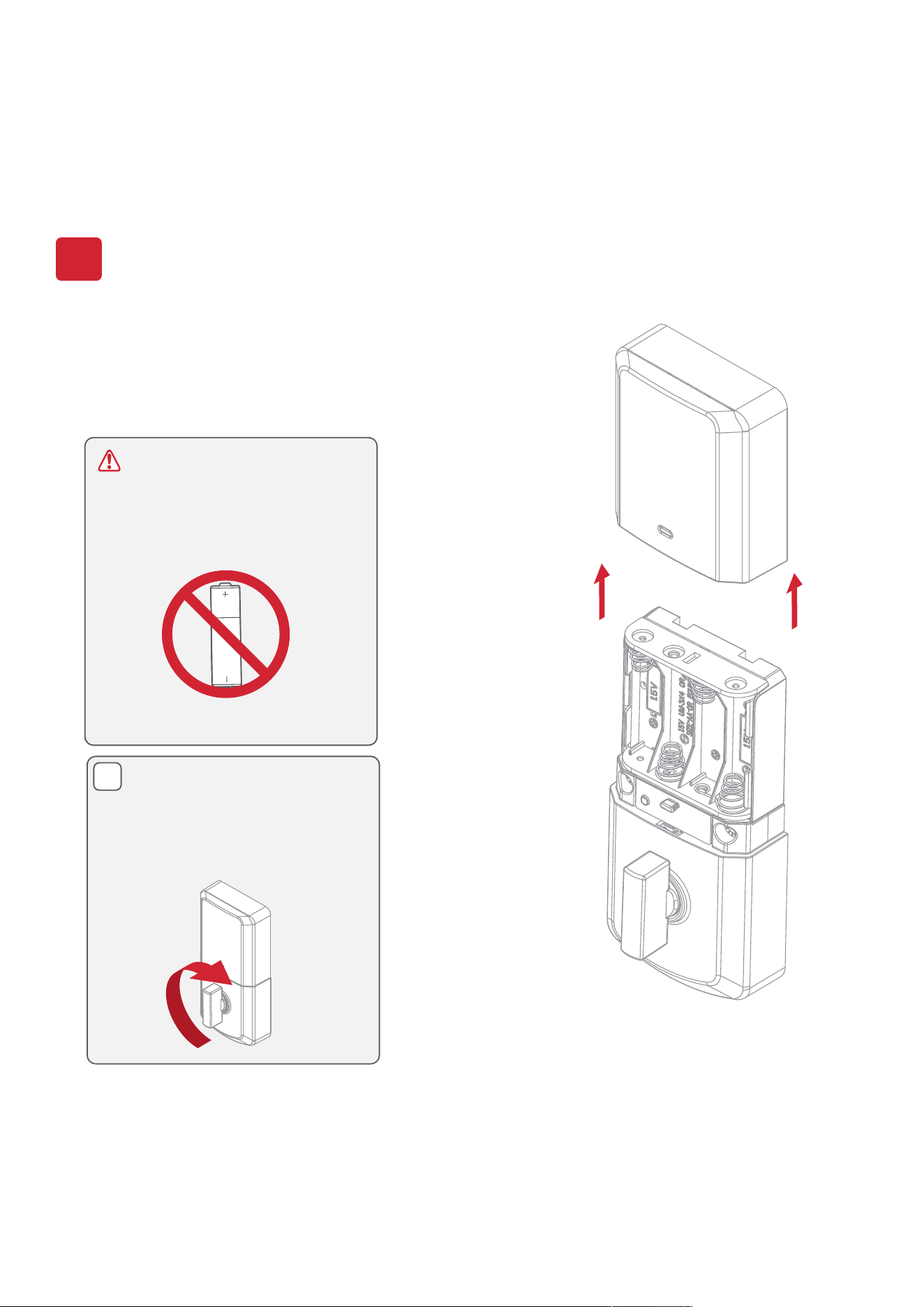
Install the interior assembly
4
Remove the interior
cover from the
interior assembly.
DO NOT install the
batteries. Wait until Step
5.
If the turnpiece is not
pointing up, rotate the
turnpiece until it’s in a
vertical position.
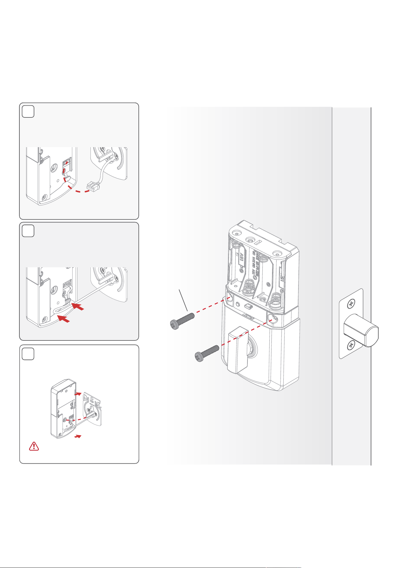
13
Secure the interior
assembly onto the
mounting plate.
[INSIDE]
D
Ensure the flat blade
fully engages with the
turnpiece shaft.
C
B
Connect the cable.
Ensure a tight cable
connection.
Excess cable will sit
inside the bottom of the
interior housing.
(2X)
52502
Ensure cable remains
connected.
14
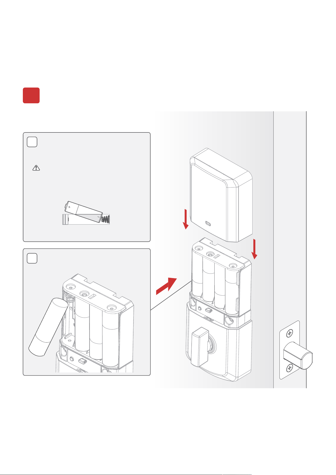
Install batteries
5
With the door open, install
the batteries.
NOTE: Lock
must be installed on the door
before inserting the batteries.
Insert (4) AA batteries (included)
into the battery pack.
[INSIDE]
Ensure correct polarity. Use new,
non-rechargeable alkaline
batteries only.
A
B
Insert the (4) AA batteries.
15
Complete your lock set up
If this lock was professionally installed (or installed by someone other
than the homeowner), make sure this step is performed by the
homeowner.
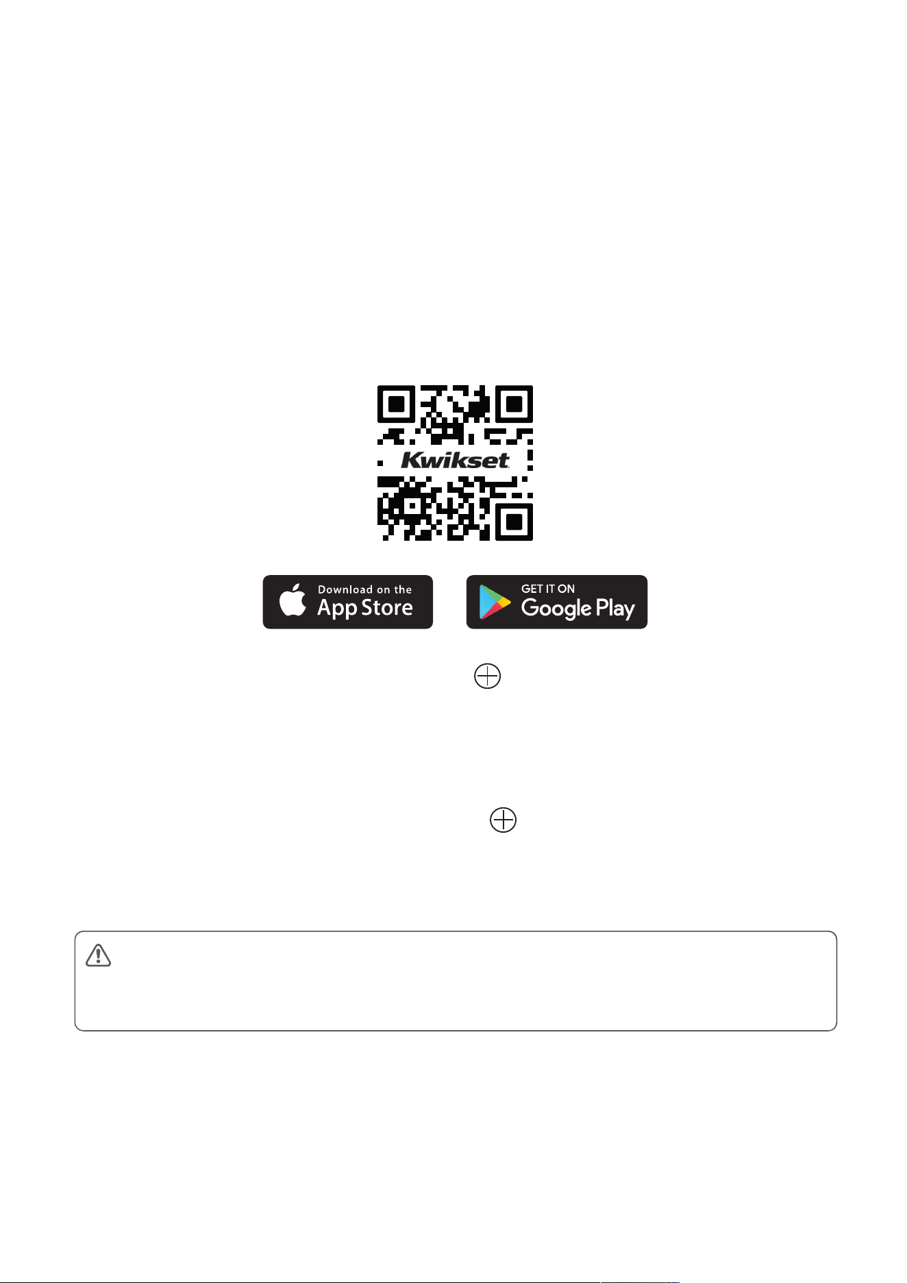
1. Download the Hubspace app.
2. Add your Lock: Tap the icon to add new
device and begin lock setup. Scan the QR code
included in the box or located on the lock interior.
3. Add Smart Plug: Tap the icon to add new
device and begin smart plug setup. Scan the QR
code included in the box or located on the plug.
16
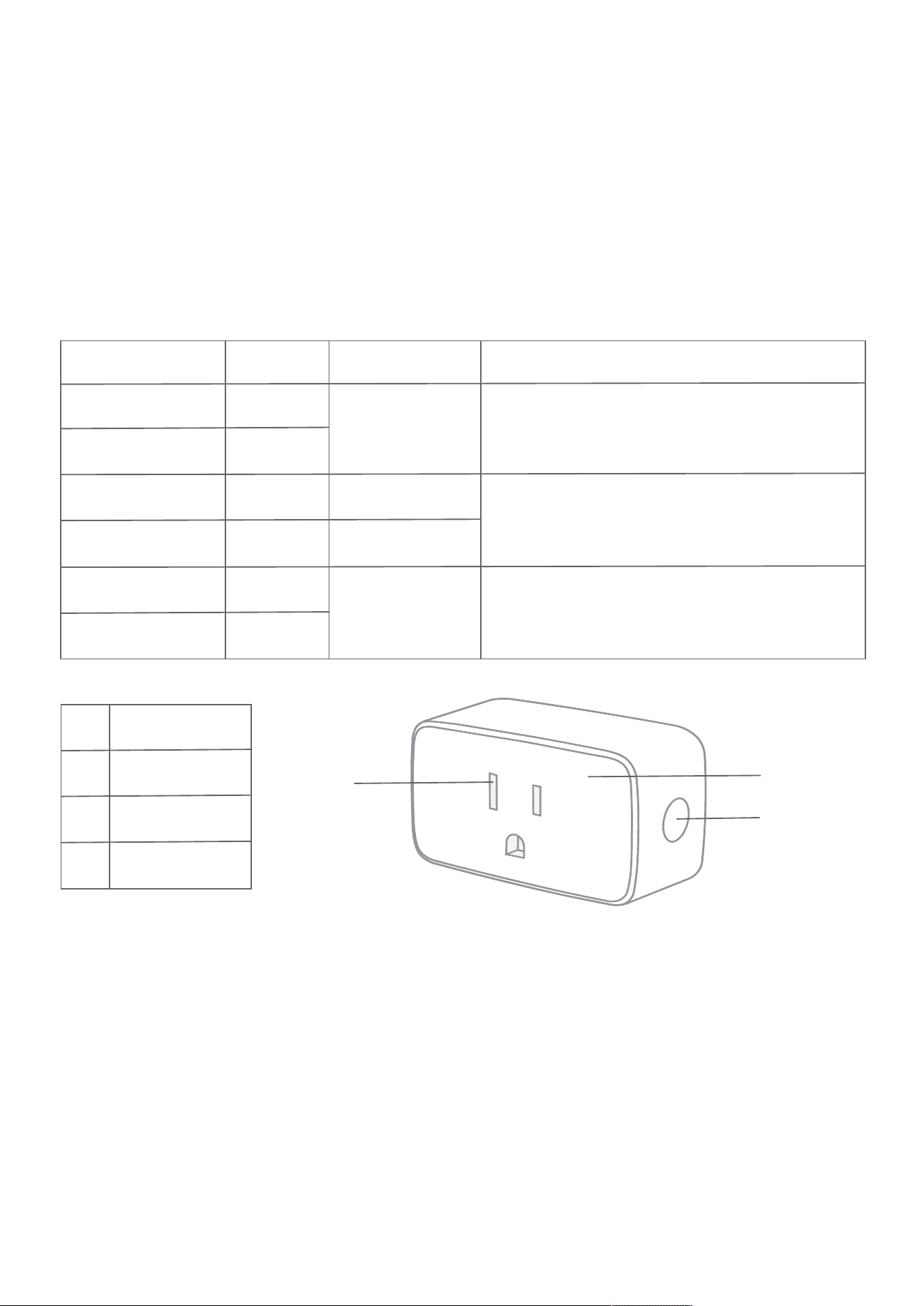
Smart Plug at a Glance
Smart Plug
LED State
Plug State
Meaning Action To Take
Orange Quick Blink
Orange/ Green
Quick Blink
O>
Green
Red
Orange
O>
O>
O>
On
On
On
The plug is o>.
The plug is on.
Wi-Fi is not
connected.
There is a Wi-Fi
error.
No action required.
Set up Wi-Fi for the product. If you have already
set up Wi-Fi for this product, wait for it to connect.
Check the Hubspace app for connectivity status.
Go to the device settings in the app and set up
Wi-Fi Access Point is allowing the device to join
the network.
Part
Description
a
Power Socket
b
Indicator Light
c
Power Button
a
b
c
Note: The range of the Bluetooth® connection is approximately 30 feet (10 meters). However, maximum
communication range will vary depending on obstacles (person, metal, wall, etc.). For best connectivity, we
recommend plugging Smart Plug in a power outlet near your lock.

Reference Guide
18
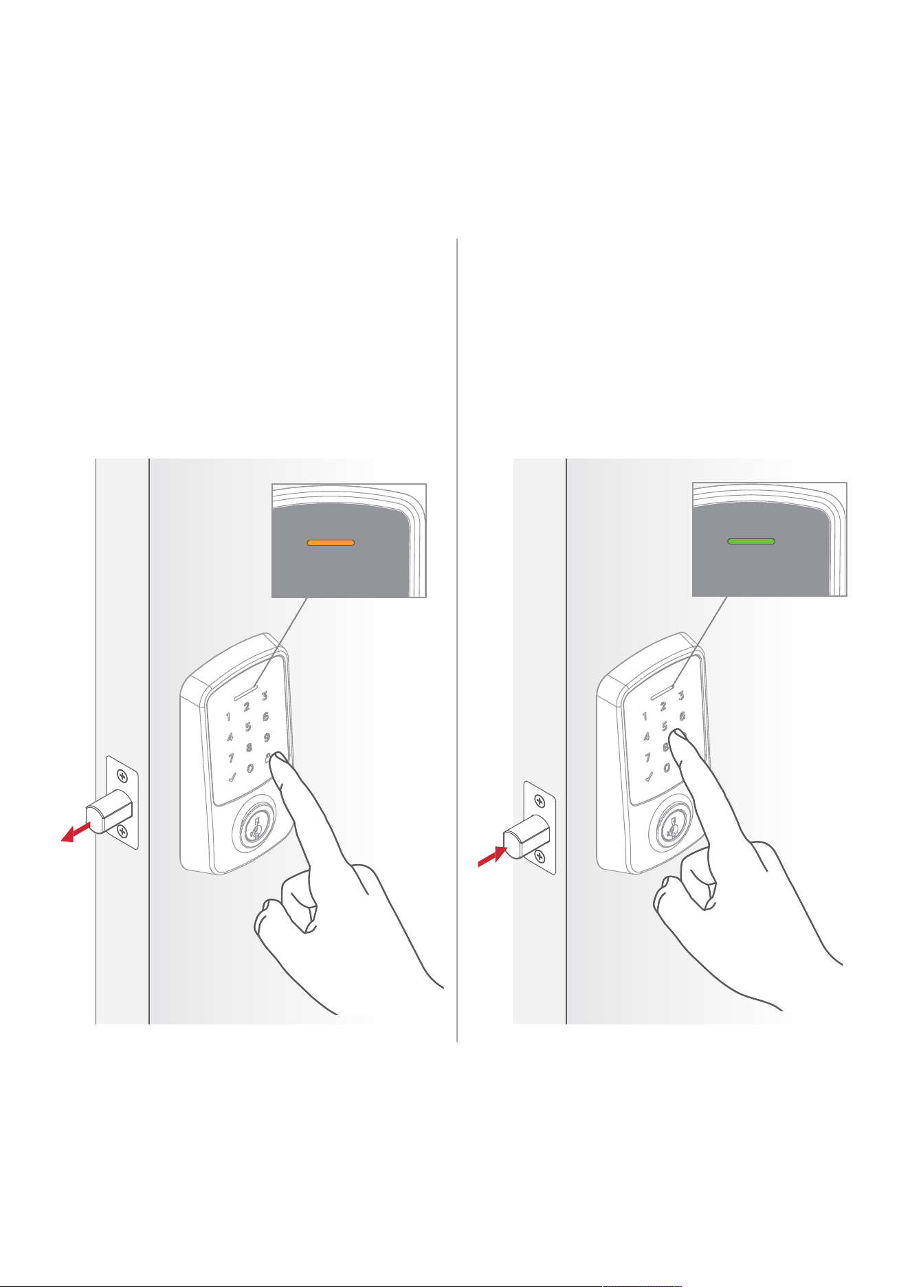
To lock your door, press the lock
icon. The bolt will extend, then the
screen will display the Locked LED
Indicator and play the locked tone.
To unlock your door, enter your
access code. The bolt will retract, then
the screen will display the Unlocked
LED Indicator and play the unlocked
tone.
Locking Unlocking
Amber status LED
will remain on
for 1.5 seconds.
Green status LED
will remain on
for 1.5 seconds.
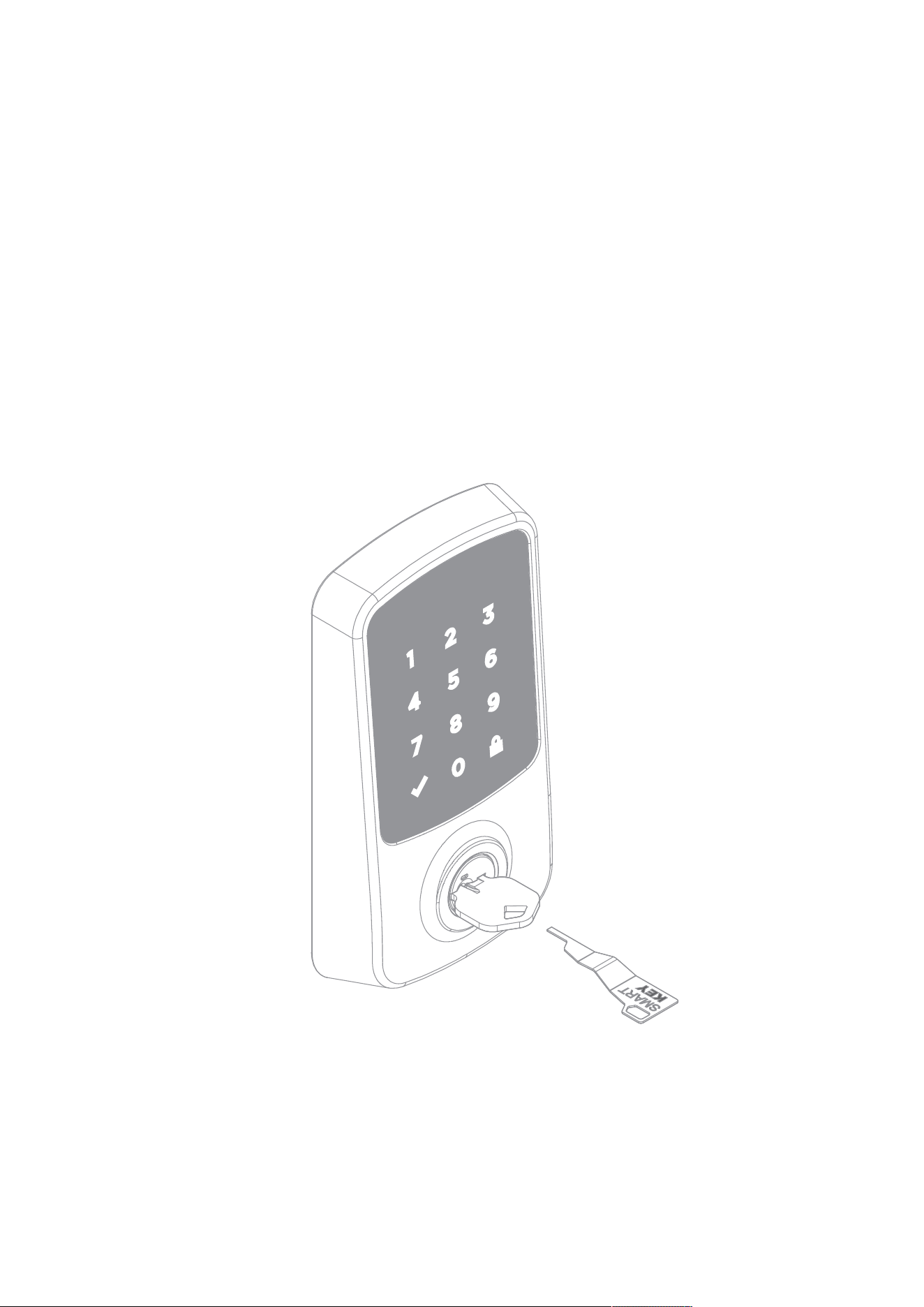
Re-key the lock to work with your existing key by following the
SmartKey® Re-key instructions.
NOTE: If Auto-Lock is enabled, remove the batteries before
re-keying your lock.
SmartKey® Re-key
19
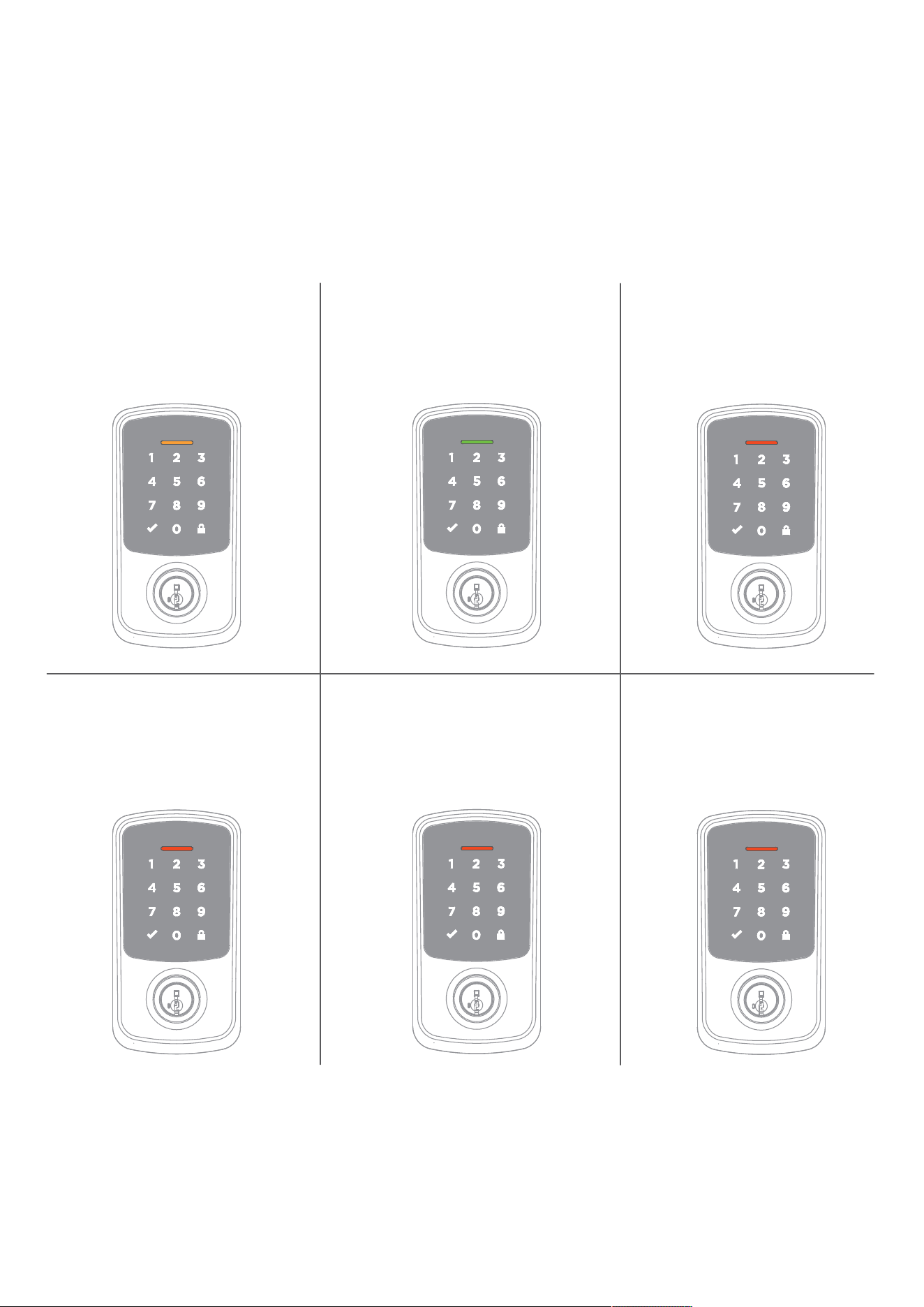
20
Amber:
Locked
Flashes
Red 3x:
Low Battery
Flashes
Red once:
Invalid Credentials
Green:
Unlocked
Exterior LED Indicators
Flashes
Red 15x:
Lockout
Red and
Keypad flashes
alternatively:
Lock Jammed
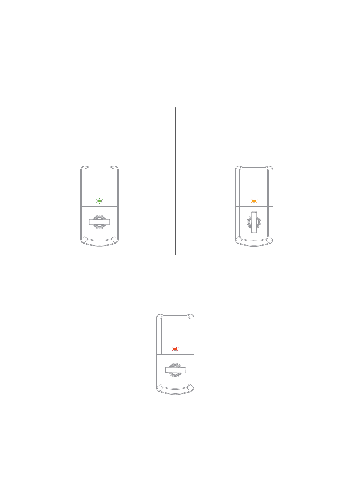
21
Green
Amber
Slow Blinking:
Unlocked
Blinking:
Low Battery
Slow Blinking:
Locked
Red
Interior Status LED Indicators

22
To remove the lock from your Hubspace account or reset lock
settings back to default, follow the below steps:
Remove Device/Reset Lock Settings
1. Open the Hubspace app
2. Select the desired lock
3. Tap the Settings Icon
4. Tap "Remove from Account"
Your lock is now ready to be set up and added to the
Hubspace app.
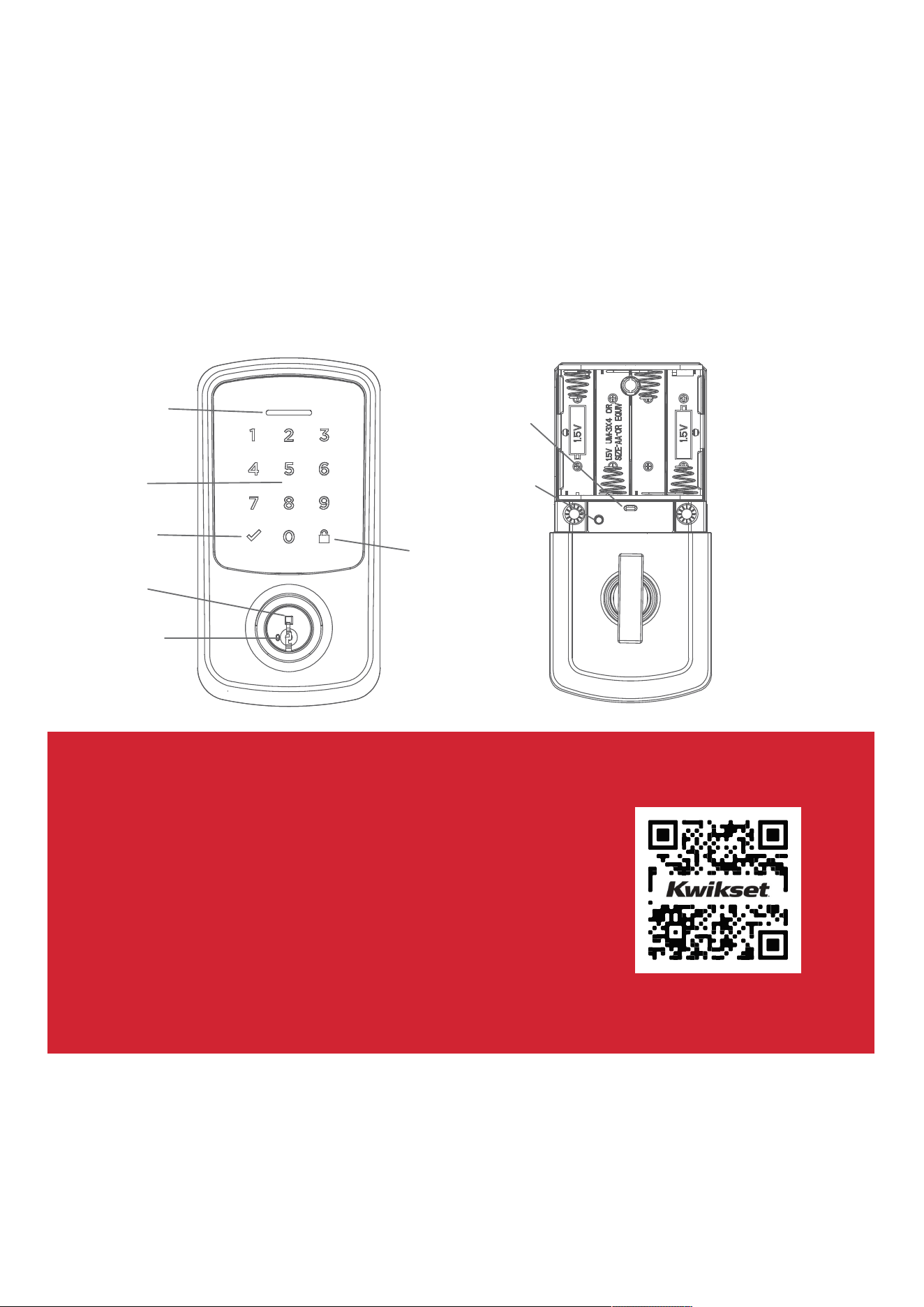
23
Wi-Fi Smart Lock at a Glance
Exterior Interior
(cover removed)
Lock
Icon
Troubleshooting
If you have any issues, please visit our
support center: kwikset.com/support
or call us at
1-800-327-5625.
Status LED
SmartKey™
tool access
Keyway
Keypad
Checkmark
Icon
Programming
Button
Status LED
24
Important Safeguards
Regulatory Compliance
1. Read all instructions in their entirety.
2. Familiarize yourself with all warning and
caution statements.
3. Remind all family members of
safety precautions.
4. Always have access to your lock’s
standard key.
5. If using the Auto-Lock features, make sure you
have your smartphone or standard key with you
to prevent locking yourself out.
6. Familiarize yourself with all light bar error
notifications.
7. Replace low batteries immediately.
8. Dispose of used batteries according to local
laws and regulations.
WARNING: This Manufacturer advises that no lock can provide complete security by itself. This lock may be defeated by
forcible or technical means, or evaded by entry elsewhere on the property. No lock can substitute for caution, awareness of
your environment, and common sense. Builder’s hardware is available in multiple performance grades to suit the application. In
order to enhance security and reduce risk, you should consult a qualified locksmith or other security professional.
FCC ID: NUL-9490
IC: 34767-GED9490
FCC Interference Statement
This product complies with standards established by the following regulatory bodies:
•Federal Communications Commission (FCC)
• Industry Canada
FCC
This device complies with Part 15 of the FCC Rules. Operation is subject to the following two conditions: (1) this device may not cause
harmful interference, and (2) this device must accept any interference received, including interference that may cause undesired
operation. This equipment has been tested and found to comply with the limits for a Class B digital device, pursuant to Part 15 of the
FCC Rules. These limits are designed to provide reasonable protection against harmful interference in a residential installation. This
equipment generates, uses, and can radiate radio frequency energy and, if not installed and used in accordance with the instructions,
may cause harmful interference to radio communications. However, there is no guarantee that interference will not occur in a particular
installation. If this equipment does cause harmful interference to radio or television reception, which can be determined by turning the
equipment oW and on, the user is encouraged to try to correct the interference by one or more of the following measures:
• Reorient or relocate the receiving antenna.
• Increase the separation between the equipment and receiver.
• Connect the equipment into an outlet on a circuit diWerent from that to which the receiver is connected.
• Consult the dealer or an experienced radio/TV technician for help.
IMPORTANT! Changes or modifications not expressly approved by the manufacturer could void the user’s authority to operate the
equipment.
Industry Canada
This device contains license exempt transmitter(s)/receiver(s) that comply with Innovation, Science and Economic Development
Canada’s license-exempt RSS(s). Operation is subject to the following two conditions: (1) This device may not cause interference. (2)
This device must accept any interference, including interference that may cause undesired operation of the device.
L’émetteur exempt de licence contenu dans le présent appareil est conforme aux CNR d’Innovation, Sciences et Développement
économique Canada applicables aux appareils radio exempts de licence. L’exploitation est autorisée aux deux conditions suivantes:
(1) L’appareil ne doit pas produire de brouillage;(2) L’appareil doit accepter tout brouillage radioélectrique subi, même si le brouillage
est susceptible d’en compromettre le fonctionnement.
RF Exposure
This equipment complies with FCC radiation exposure limits set forth for an uncontrolled environment. This equipment should be
installed and operated with a minimum distance of 20 cm between the radiator and a human body.
This equipment complies with ISED radiation exposure limits set forth for an uncontrolled environment. This equipment should be
installed and operated with a minimum distance of 20 cm between the radiator and a human body.
Cet équipement est conforme aux limites d'exposition aux rayonnements ISED établies pour un environnement non contrôlé. Cet
équipement doit être installé et utilisé avec une distance minimale de 20 cm entre le radiateur et un corps humain.