SP5000 Portable Power Station
Split Phase
User manual
Version:V2.0
I
About This Manual
This manual describes the product information, installation, electrical connection, commissioning, troubleshooting, and
maintenance. Read through this manual before installing and operating the product. All the installers and users have to be
familiar with the product features, functions, and safety precautions. This manual is subject to update without notice.
Features
1. Power low-voltage and high-voltage loads.
2. Max. 3450W AC super charge.
3. 2.56~10.24kWh expandable battery capacity.
4. Max. 5000W high power AC output.
5. 10ms auto-transfer from on grid to off grid.
6. APP smart control.
Applicable Model
The manual does not contain complete information about photovoltaic (PV) systems.
This manual is only for products below:
Model
Output power rating
Battery capacity
SP5000
5000W
5.12kWh
Target Audience
This manual applies to trained and knowledgeable technical professionals. The technical personnel have to be familiar with
the product, local standards, and electric systems.
How to Use This Manual
Read the manual and other related documents before performing any operation on the inverter. Documents must be stored
carefully and be available at all times.
Contents may be periodically updated or revised due to product development. The information in this manual is subject to
change without notice.
Symbol Explanation
SP5000 Portable Power Station is designed and tested in strict accordance with international safety regulations. Read all
safety instructions carefully prior to any work and observe them at all times when working on or with the inverter operation
and maintenance, as any improper operation might cause personal injury or property damage.
DANGER indicates danger that, if not avoided, will result in death or serious injury.
WARNING indicates a warning that, if not avoided, may result in death or serious injury.
CAUTION indicates a caution, if not avoided, may result in minor or moderate injury.
NOTICE Indicates hints, highlights key information.
Potential risks exist. Wear proper PPE
before any operations.
DANGER High voltage hazard.
Disconnect all incoming power and turn
off the product before working on it.
High-temperature hazard. Do not touch
the product under operation to avoid
being burnt.
Do not touch live parts for 5 minutes after
disconnecting from the power sources.
The components of the product can be
recycled.
Products shall not be disposed as
household waste.
Read through the user manual before
any operations.
CE mark.
Do not disconnect under load.
FCC
DANGER
WARNING
CAUTION
NOTICE

Contents
About This Manual ...............................................................................................................................................I
Features ............................................................................................................................................................. I
Applicable Model .............................................................................................................................................. I
Target Audience ................................................................................................................................................ I
How to Use This Manual ................................................................................................................................. I
Symbol Explanation ..........................................................................................................................................I
1 Safety Instructions ...........................................................................................................................................1
1.1 General ....................................................................................................................................................... 1
1.2 Installation .................................................................................................................................................. 1
1.3 Electrical Connection ................................................................................................................................ 2
1.4 Operation .................................................................................................................................................... 2
1.5 Maintenance ...............................................................................................................................................2
1.6 Battery Safety Instruction .........................................................................................................................2
2 Product Introduction ....................................................................................................................................... 4
2.1 Product Overview ...................................................................................................................................... 4
2.2 Display Screen ...........................................................................................................................................4
3 Storage ................................................................................................................................................................7
4 Installation ..........................................................................................................................................................8
4.1 Check before Unpacking ..........................................................................................................................8
4.2 Packing List ................................................................................................................................................ 8
4.3 Operating Environment ............................................................................................................................ 9
4.4 Maximum Battery Expansion ................................................................................................................ 10
4.5 Usage Clearance .....................................................................................................................................10
4.6 Mounting Battery Packs ......................................................................................................................... 11
5 Operating Instruction ....................................................................................................................................13
5.1 System Overviews .................................................................................................................................. 13
5.2 Button Instructions .................................................................................................................................. 14
5.3 Charging Instructions ..............................................................................................................................17
6 Failure and Maintenance ..............................................................................................................................18
6.1 Failure Display and Troubleshooting ................................................................................................... 18
6.2 Maintenance .............................................................................................................................................19
7 Specification ....................................................................................................................................................20
1
1 Safety Instructions
Please strictly follow these safety instructions in the user manual during the operation.
NOTICE
■The inverter has been designed and tested strictly according to international safety regulations. Read all
safety instructions carefully prior to any work and observe them at all times when working on or with the
inverter.
■ Personnel who install or maintain the equipment must be strictly trained and learn about safety
precautions and correct operations.
■ Only qualified professionals or trained personnel are allowed to install, operate, maintain, and replace
the equipment or parts.
■ Appropriate methods must be adopted to protect the inverter from static electricity damage. Any damage
caused by static electricity is not warranted by the manufacturer.
1.1 General
DANGER
■ Ensure that the inverter is not connected to a power supply or powered on before finishing installation or
during replacement and maintenance.
■ Do not open the inverter cover or change any components without manufacturer's authorization.
Otherwise, the warranty for the inverter will be invalid.
■ Any installation or operations on the inverter must be performed by qualified electricians in compliance
with standards, wiring rules and the requirements of local grid authorities or companies.
■ All labels and warning marks should be visible after the installation. Do not cover, scrawl, or damage any
label on the equipment.
NOTICE
■ The information in this user manual is subject to change due to product updates or other reasons. This
manual cannot replace the product safety labels unless otherwise specified. All descriptions here are for
guidance only.
■ Before installations, read through the user manual to learn about the product and the precautions.
■ All operations should be performed by trained and knowledgeable technicians who are familiar with local
standards and safety regulations.
1.2 Installation
DANGER
■ Never power on the inverter during installation.
■ Use insulating tools and wear personal protective equipment when operating the equipment to ensure
personal safety. Wear anti-static gloves, clothes, and wrist strips when touching electronic devices to
protect the inverter from damage.
■ Install in areas where children can not access.
2
■ Make sure DC input voltage does not exceed the maximum input voltage of the inverter.
1.3 Electrical Connection
DANGER
■ Ensure that the inverter is secured in position before connecting cables, or it can cause personal injury.
■ Ensure that the cables used in the system are properly connected and insulated and meet all
specification requirements.
■ Connect the inverter cable to the supplied terminals. If other types of terminals are used, serious
damage may occur for which the manufacturer is not responsible.
WARNING
■ The voltage and frequency at the connecting point should meet the on-grid requirements.
■ Additional protective devices like circuit breakers or fuses are recommended on the AC side.
Specification of the protective device should be at least 1.25 times the maximum AC input current.
1.4 Operation
DANGER
■ When the inverter is operating, do not disconnect under load.
WARNING
■ The temperature of the inverter surface can exceed 60℃ during operation. Make sure it has cooled
down before touching it and make sure the inverter is out of reach of children.
1.5 Maintenance
DANGER
■ High voltage may cause an electric shock, which results in serious property damage, serious injury, or
death, or serious property damage Prior to maintenance, power off the inverter and strictly comply with the
safety precautions in this document.
■ Before performing maintenance tasks, power off the inverter and wait at least 5 minutes.
1.6 Battery Safety Instruction
DANGER
■ Use the multi-meter to measure the DC cable to avoid reverse polarity connection. Also, the voltage
should be under the permissible range.
WARNING
■ Before installation, thoroughly read the SP5000 user manual to familiarize yourself with the product and
its safety precautions.

3
Strictly adhere to the following guidelines:
■ If the battery is completely discharged, charge it according to the instructions provided in the
corresponding model’s user manual.
■ Environmental factors such as temperature, humidity, and weather conditions may limit the battery’s
current and impact its load capacity.
■ If the battery fails to start, contact after-sales service immediately. Failure to do so may result in
permanent damage to the battery.
■ Do not connect a single battery pack to multiple inverters simultaneously, as this may cause damage to
the inverter.
4
2 Product Introduction
2.1 Product Overview
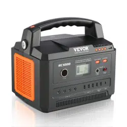
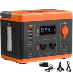
The SP5000 Portable Power Station (Split Phase) is a portable power supply unit equipped with a built-in
LiFePO4 battery and a bi-directional inverter. The battery can be charged using both AC power and solar
panels. With the bi-directional inverter, AC charging power is increased, resulting in faster charging speeds.
The high-capacity lithium battery provides extended power to connected loads. During AC charging, the
internal bypass relay allows the load to be powered directly from the mains.
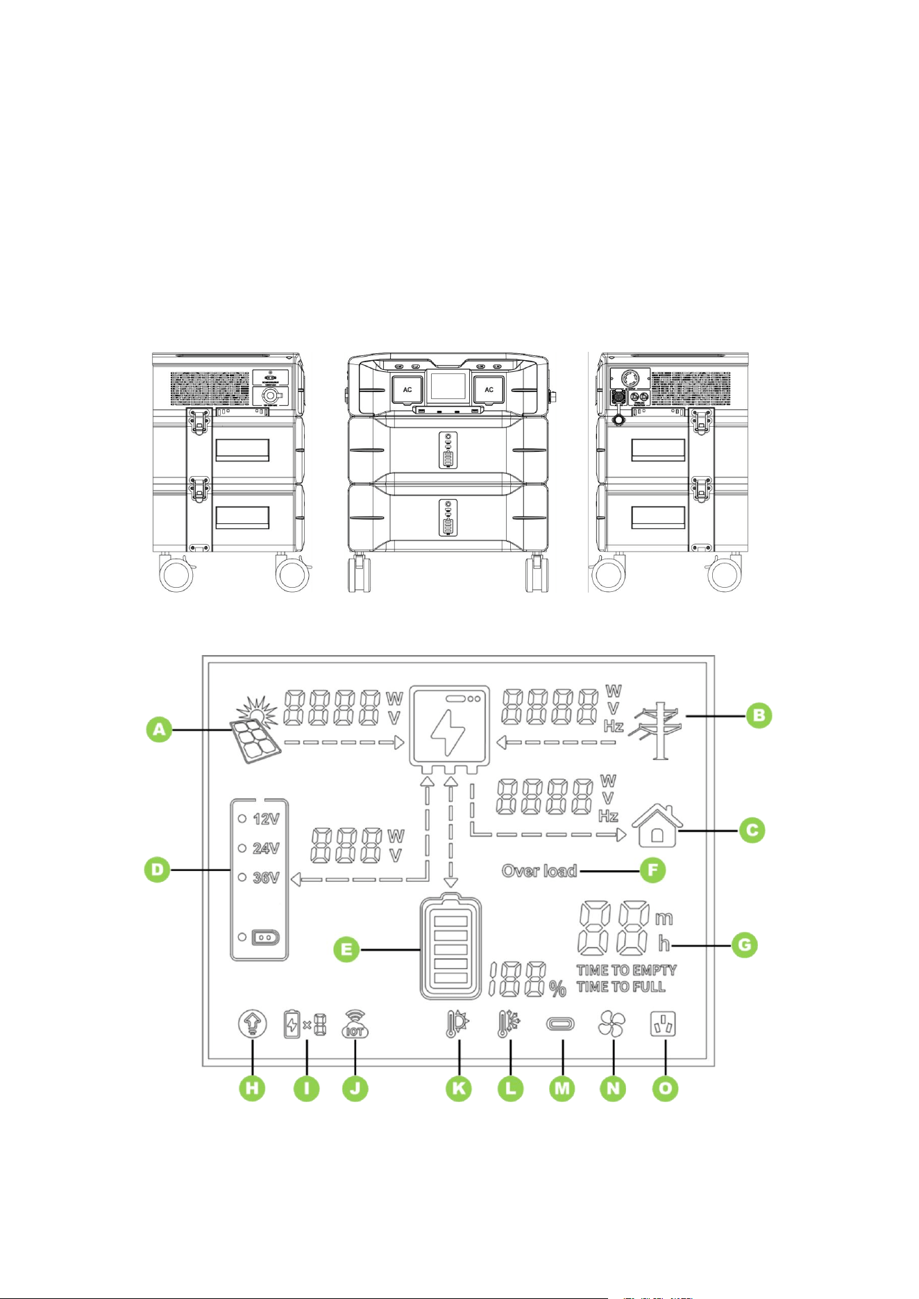
Appearance
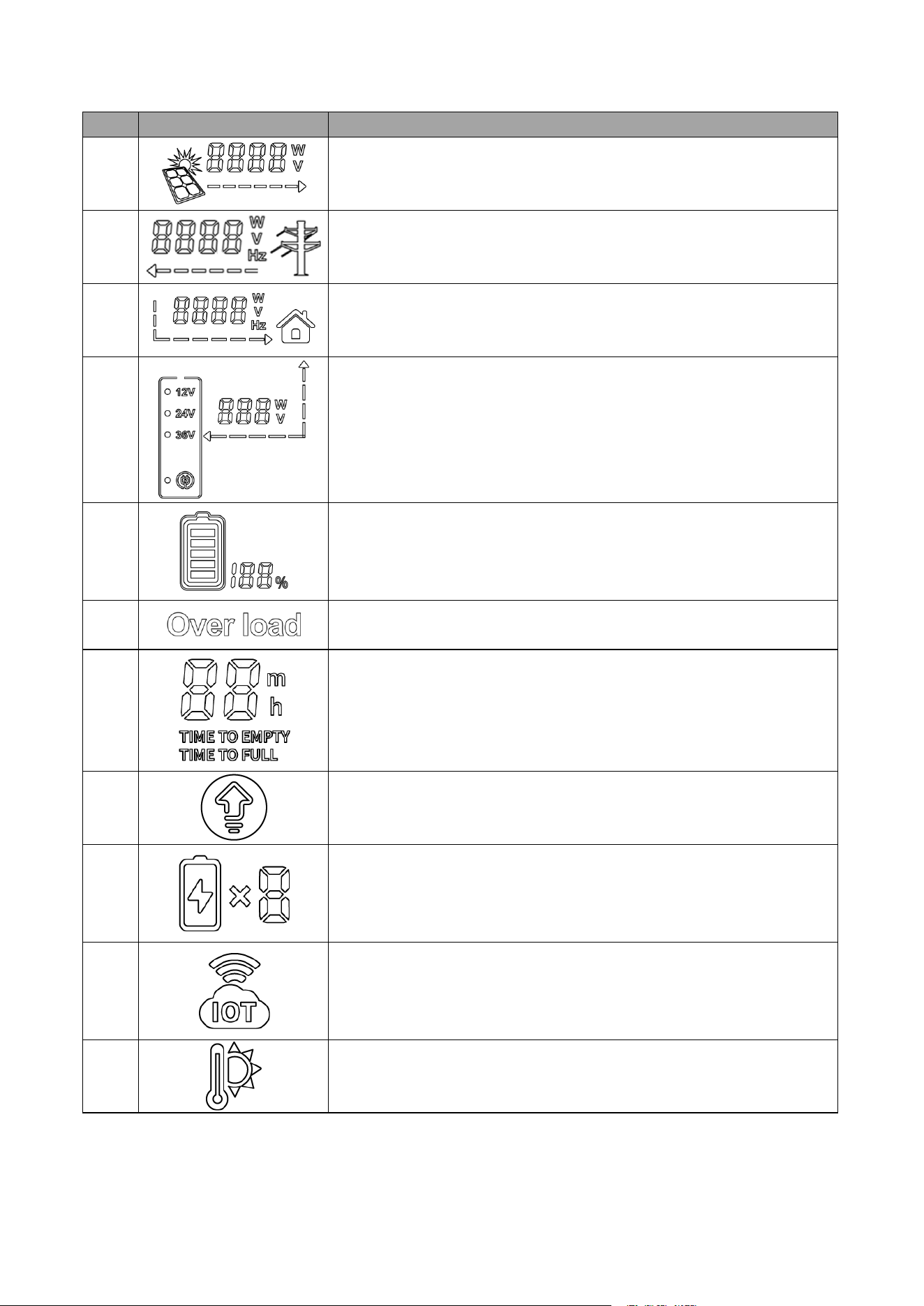
2.2 Display Screen
The icon on the inverter display indicates the current operating status of the inverter.
5
No.
Icon
Description
A
Indicates PV charging status and displays PV charging power in real
time.
B
Indicates the charging status of the grid and displays the charging
power of the grid in real time.
C
Indicates AC discharge status and displays AC discharge power in
real time.
D
1. Indicates the low-voltage PV charging status and real-time display
of low-voltage PV charging power.
2. Three selectable output voltages: 12V, 24V, and 36V.
3. DC charging mode.
E
Indicates battery charging/discharging status and displays the battery
SOC in real time.
F
Indicates that the device is overloaded.
G
Indicates the time to be empty discharged or fully charged.
H
Indicates AC constant power mode.
I
Indicates the number of battery packs.
J
Indicates monitoring connection status.
K
Indicates over-temperature fault.

6
L
Indicates under-temperature fault.
M
Indicates the active status of the PD Type-C interface.
M
Indicates fan active status.
O
Indicates that the AC is active.

7
3 Storage
For long-term storage, the product should be discharged to 0% and recharged to 100% at least once every
three months. Failing to do so may significantly reduce the battery lifespan.
NOTICE
Storage Requirements for the SP5000:
■ Do not unpack the outer packaging.
■ Store the SP5000 in an environment with a temperature range of –20°C to +50°C and humidity between
5% and 95% RH, ensuring no condensation.
■ Keep the SP5000 in a clean, dry location, protected from dust and moisture.
■ Follow the stacking instructions on the packaging for proper height and direction when stacking
inverters.
■ Handle the SP5000 with care during stacking to prevent them from falling.
■ Conduct regular inspections during storage and replace packing materials as needed.
■ After long-term storage, the SP5000 must be inspected and tested by qualified personnel before use.
8
4 Installation
4.1 Check before Unpacking
NOTICE
Inspection Checklist Upon Receiving the Product:
■ Inspect the packaging for any damage, such as holes, cracks, or other signs of potential equipment
damage. If any damage is found, do not unpack the product and contact the supplier immediately.
■ Verify that the inverter model matches your order. If the model is incorrect, do not unpack the product
and contact the supplier.
■ Ensure that all inverter accessories are included and in good condition. If any items are missing or
damaged, contact the supplier immediately.
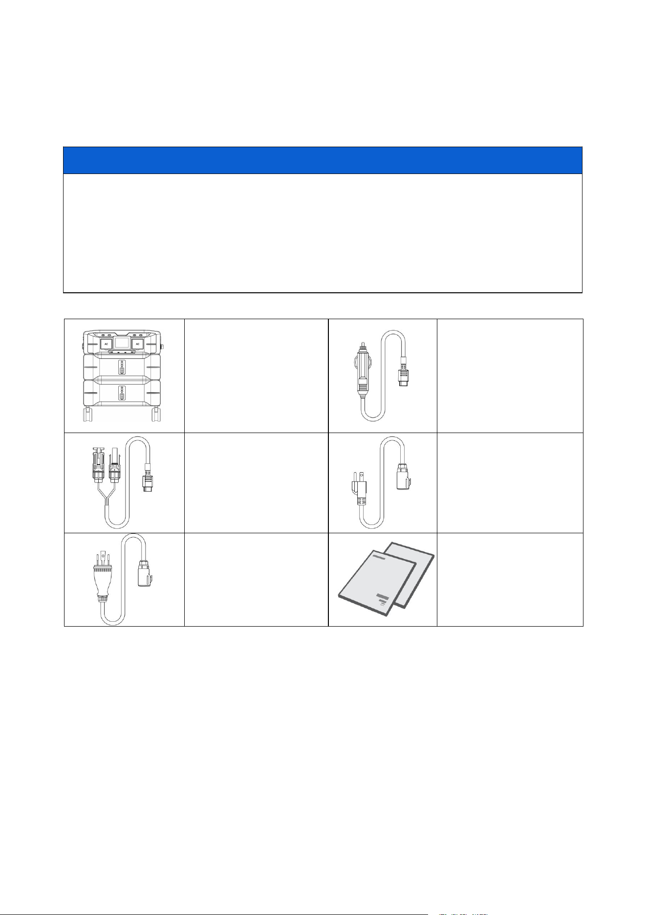
4.2 Packing List
Inverter *1
Battery *2
Car charging cable *1
Solar charging cable *1
120V AC charging cable *1
240V AC charging cable *1
User manual *1
Warranty card *1
9
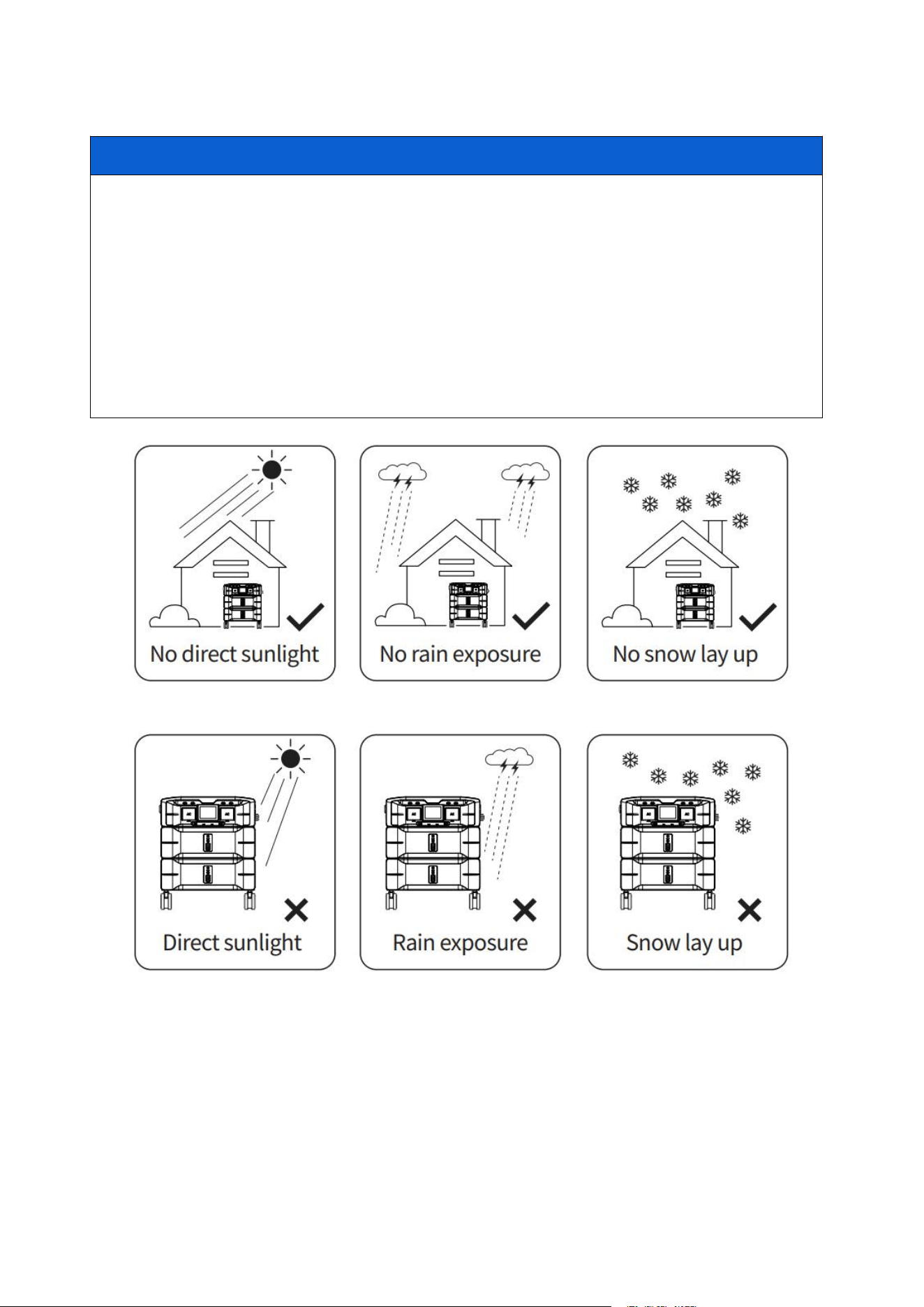
4.3 Operating Environment
NOTICE
Environmental Requirements for Use:
1. Do not place the equipment near flammable, explosive, or corrosive materials.
2. Keep the equipment out of reach of children. The equipment operates at high temperatures—avoid
touching the surface to prevent burns.
3. Use the equipment in a sheltered area, protected from direct sunlight, rain, and snow.
4. Ensure the location is well-ventilated to allow for proper heat dissipation and provides adequate space
for operation.
5. The temperature and humidity at the installation site should remain within the recommended range.
6. The maximum operating altitude should not exceed 2000 meters.
7. Adhere to these guidelines to maximize the lifespan of the inverter.
10
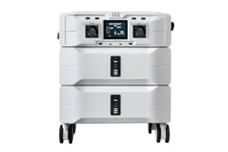
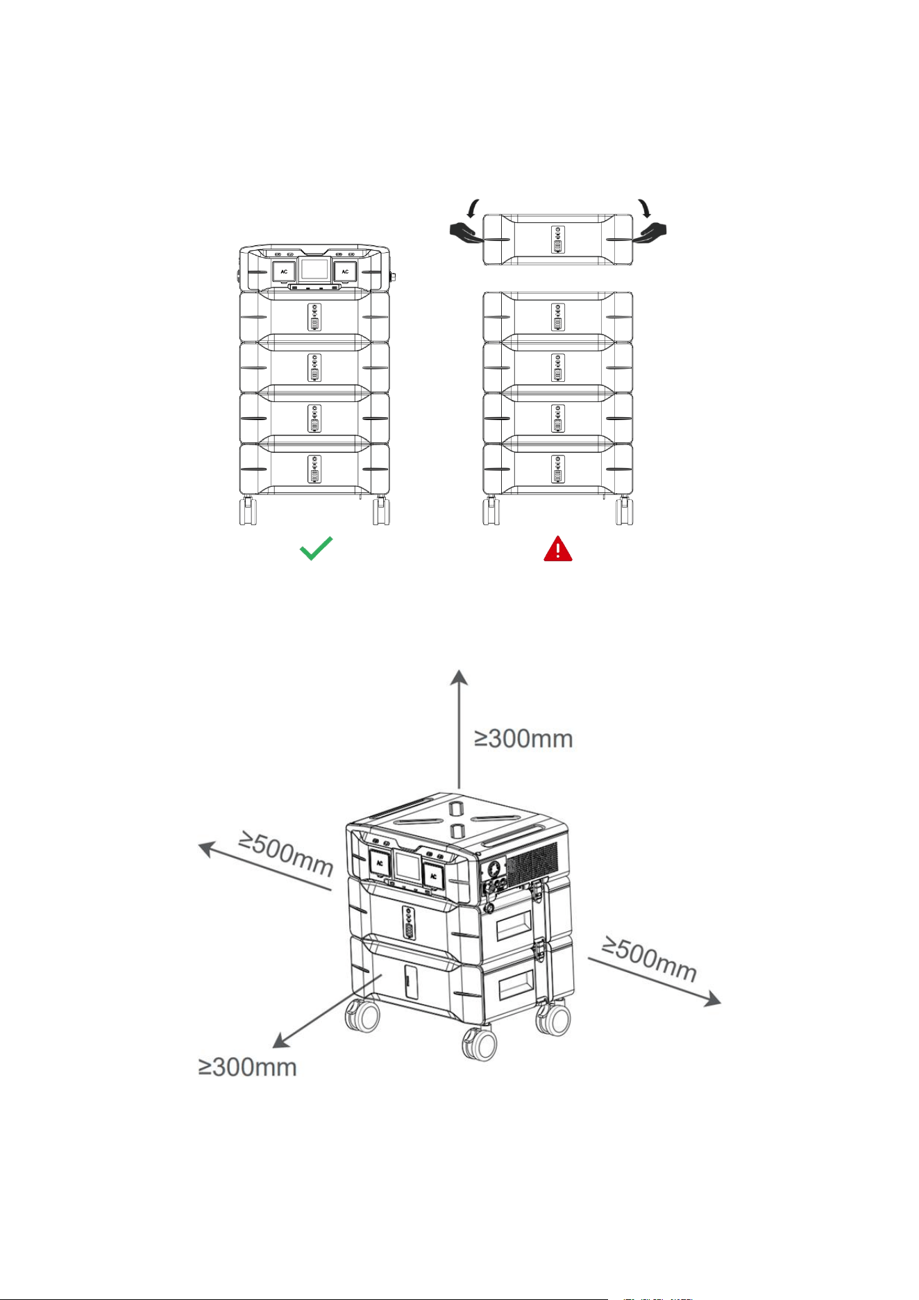
4.4 Maximum Battery Expansion
For optimal performance and safe transportation, the SP5000 supports battery expansion of 4 units (total
capacity: 10.24 kWh). Exceeding this limit may negatively affect the product's mobility.
4.5 Usage Clearance
For optimal heat dissipation and ease of dismantling, the minimum clearance around the inverter should not
be less than the values specified below.
11
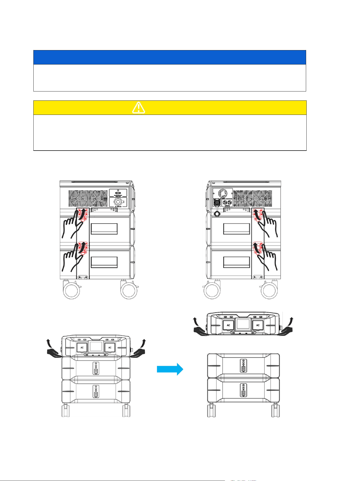
4.6 Mounting Battery Packs
NOTICE
■ To expand the battery pack, please purchase only the official matching standard battery. Using a
non-matching or unofficial battery pack may damage the inverter.
■ Follow the steps below to expand the battery pack.
CAUTION
■ Before disassembling, ensure that the load is disconnected, the power is turned off, and the battery is
powered down. Failure to do so may result in a short circuit, leakage, or damage to the inverter, posing a
risk of injury.
■ It is recommended that two or more personnel be involved in the battery pack installation process.
Step 1: Unlock the metal snap between the inverter and the battery pack.
Step 2: Removing the inverter.
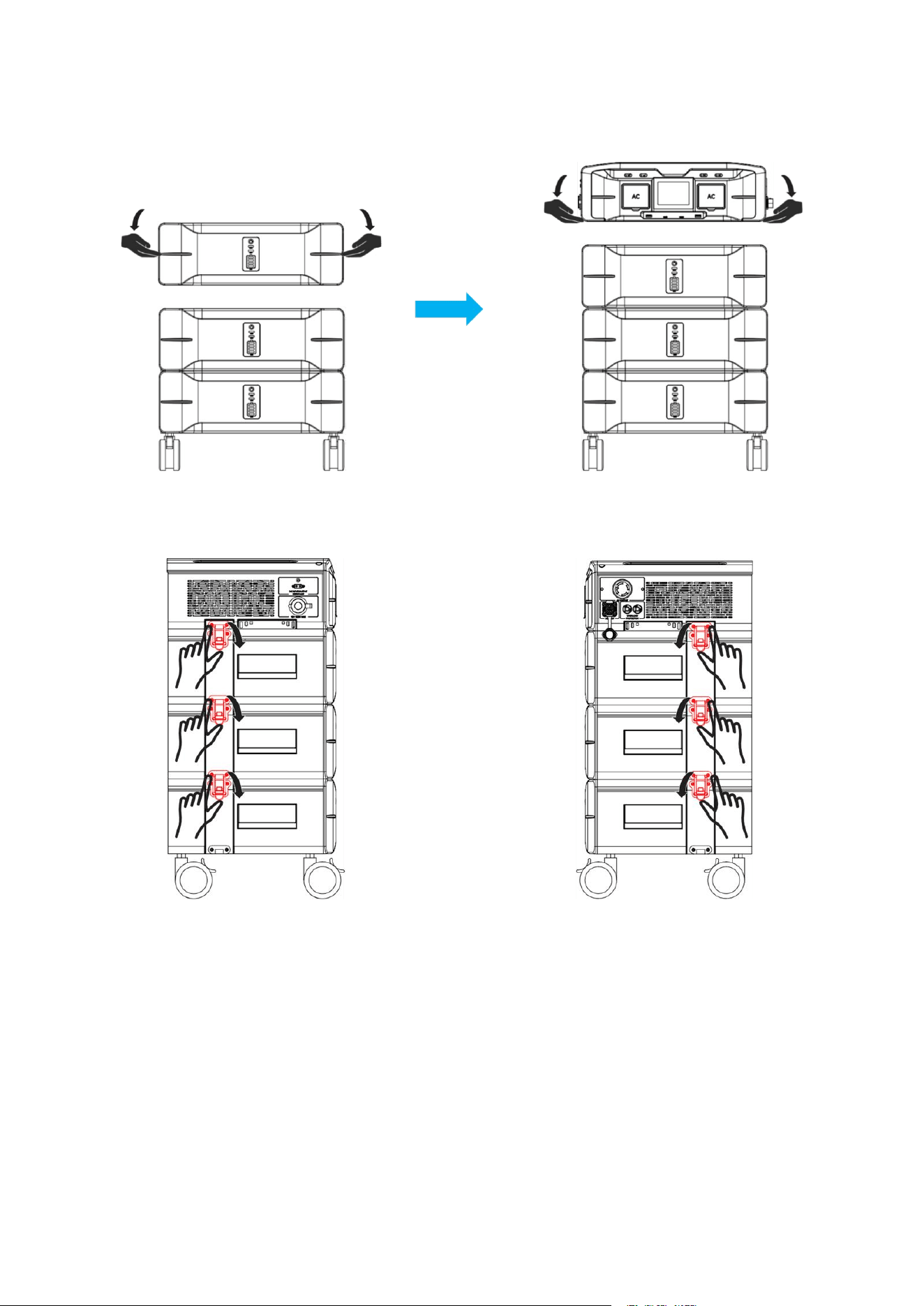
12
Step 3: Mounting a new battery pack.
Step 4: Re-lock the metal snap between the inverter and the battery pack.
13
5 Operating Instruction
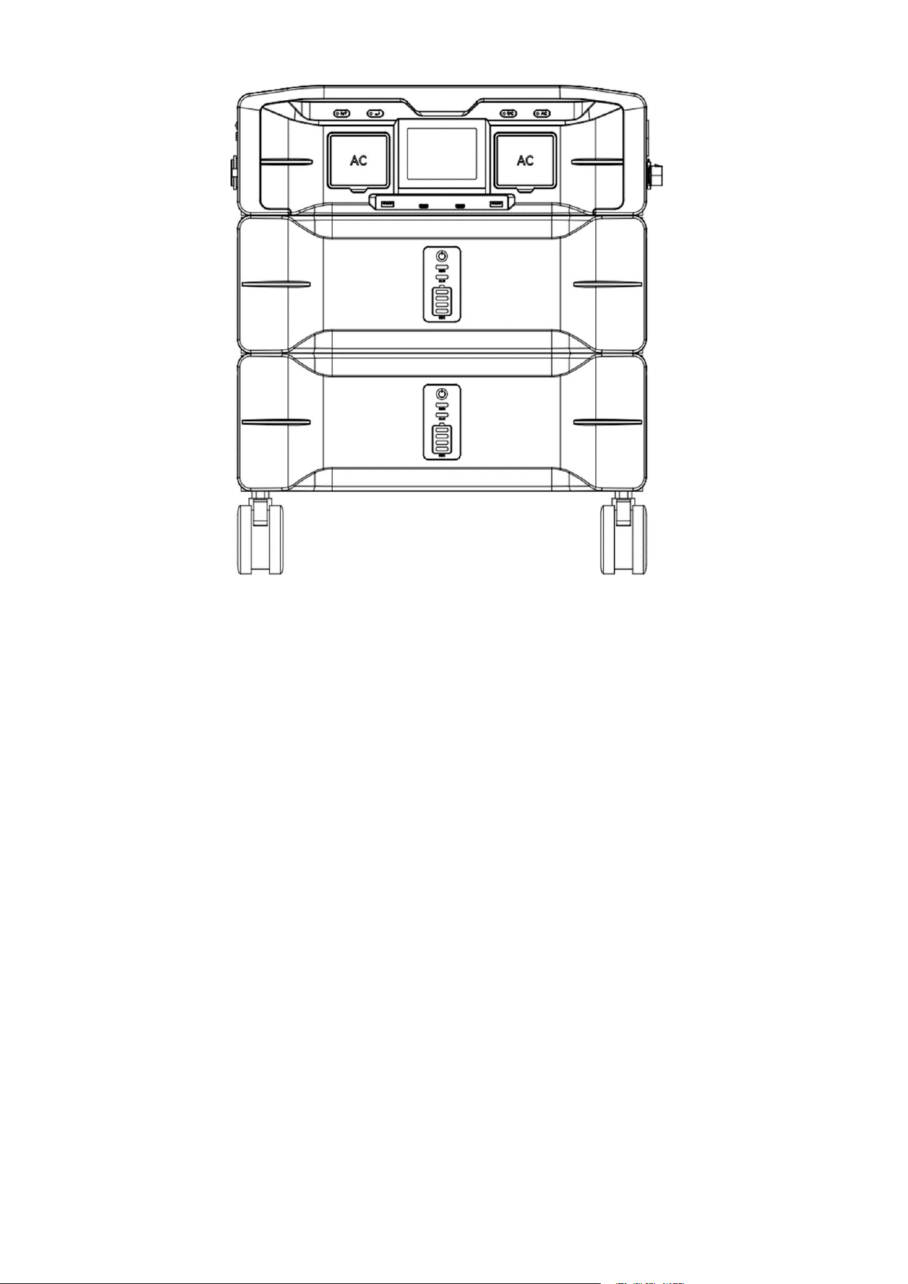
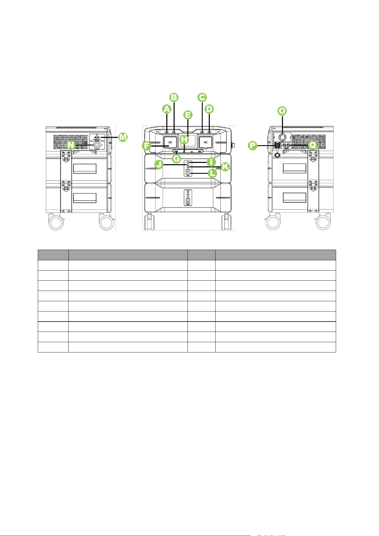
5.1 System Overviews
NO.
Description
NO.
Description
A
IoT Reset Switch
J
Operation Indicator
B
Display Mode Button
K
Fault Warning Indicator
C
DC ON/OFF Switch
L
Battery SoC Display
D
AC ON/OFF Switch
M
Solar Input or DC Output (XT60)
E
Display Screen
N
Cigarette lighter outlet
F
120V AC Output
O
240V AC Output
G
USB-A
P
AC Input
H
Type-C
Q
Overload protector
I
Power ON/OFF Switch
14
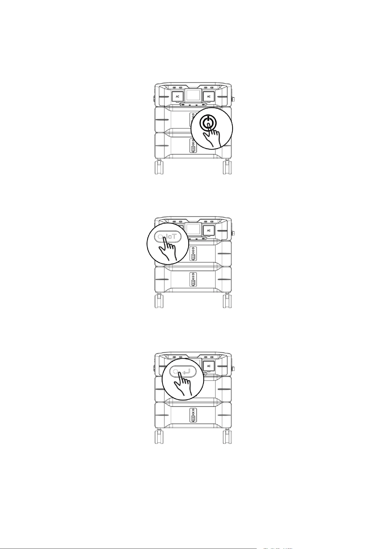
5.2 Button Instructions
① Press and hold the ‘Power ON/OFF Switch’ for 3 to 5 seconds to turn the machine ON and OFF.
② Press and hold the ‘IoT Reset Switch’ for 3 to 5 seconds (WiFi icon blinks) to pair with WiFi. Double-click
the ‘IoT Reset Switch’ to exit the WiFi pairing status.
③ Press the 'Display Mode Button' to cycle through the screen display pages. The first click shows the
power of L1, the second click shows the voltage of L1, the third click shows the power of L2, and the fourth
click shows the voltage of L2.
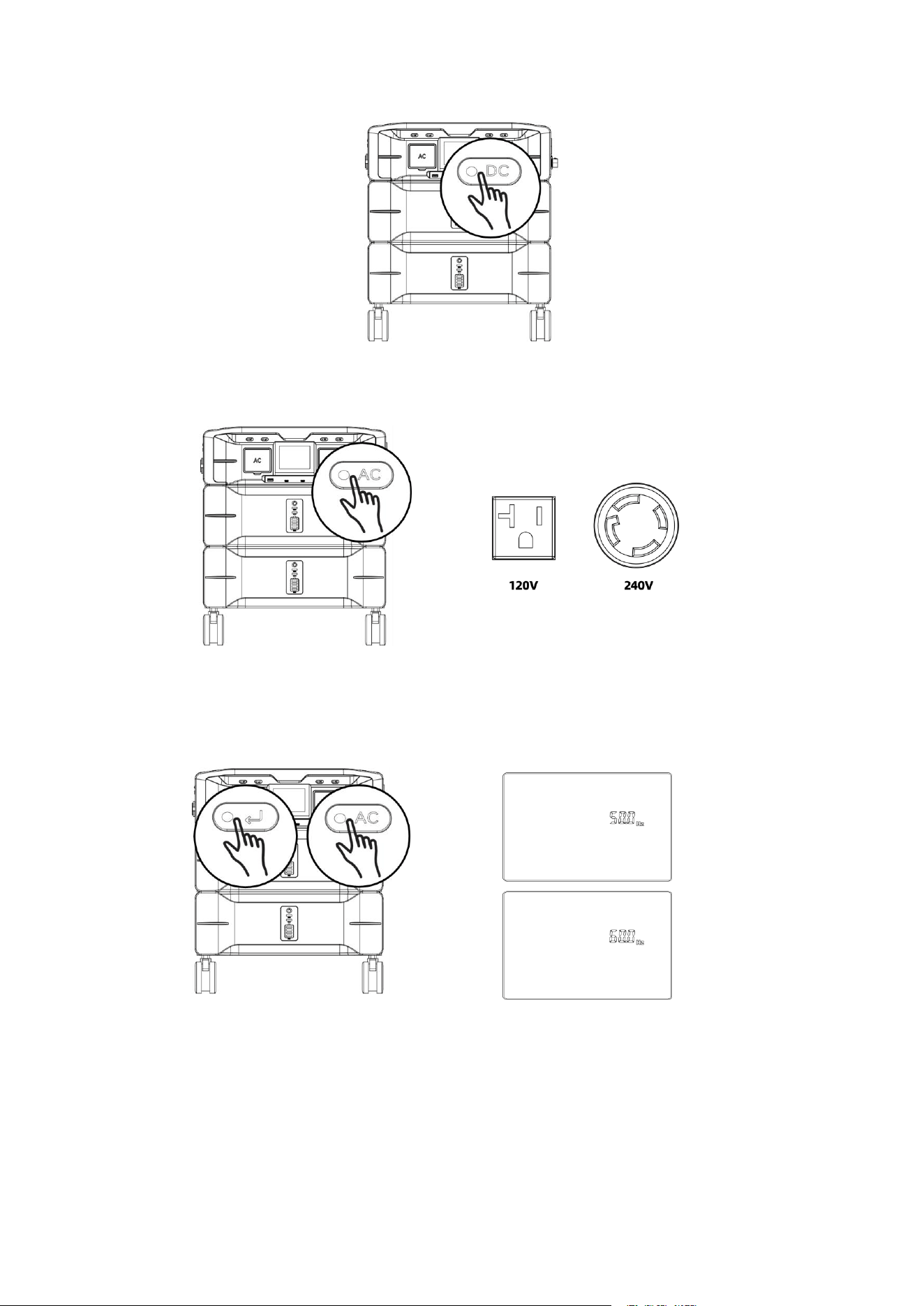
④ Click the ‘DC ON/OFF Switch’ to turn ON/OFF the cigarette lighter outlet. (Car icon appears/disappears
on the display)
15
⑤ Click the ‘AC ON/OFF Switch’ to turn ON/OFF the 120V and 240V AC output.
⑥ Press and hold the ‘AC ON/OFF Switch’ and ‘Display Mode Button’ simultaneously for 3 seconds to
switch between 50Hz and 60Hz frequency. During charging, the output frequency synchronizes to and
remains aligned with the grid frequency.
⑦ Press and hold the ‘DC ON/OFF Switch’ to view the software version number and start the fan self-test.
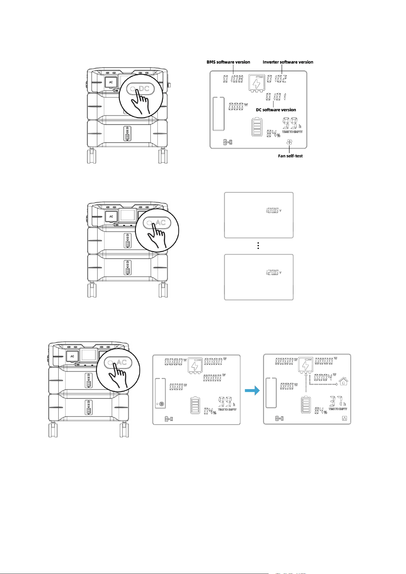
16
⑧ Double-click five-time the ‘AC ON/OFF Switch’ to change the AC output voltage.
⑨ Click the ‘AC ON/OFF Switch’ to turn ON/OFF the constant power mode.
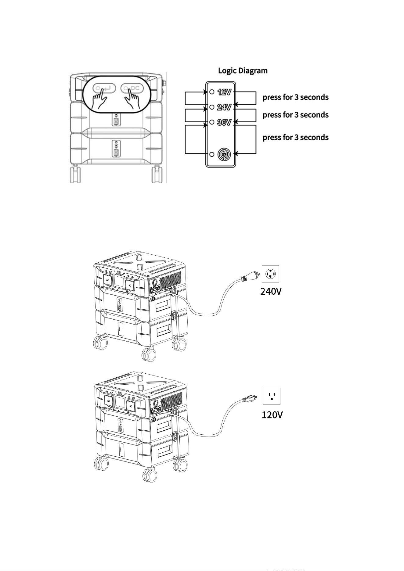
⑩ Press and hold the ‘DC ON/OFF Switch’ and ‘Display Mode Button’ simultaneously for 3 seconds to
switch between the XT60 port's discharge mode (Voltage Levels: 12V/24V/36V) and DC charging mode.
17
5.3 Charging Instructions
The SP5000 is compatible with both 120V and 240V charging using the provided AC charging cables. When
using the 240V AC charging cable, the unit supports a 3450W fast charging. When using the 120V AC
charging cable, the unit supports a 1800W standard charging.
18
6 Failure and Maintenance
If the following issues occur, refer to the solutions below. If unresolved, please contact your local
distributor. The table provides common operational scenarios with recommended troubleshooting steps.
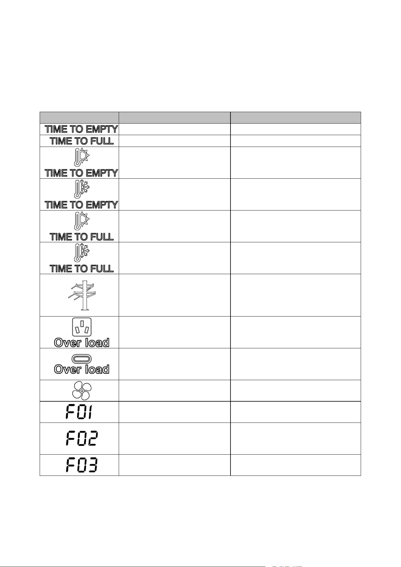
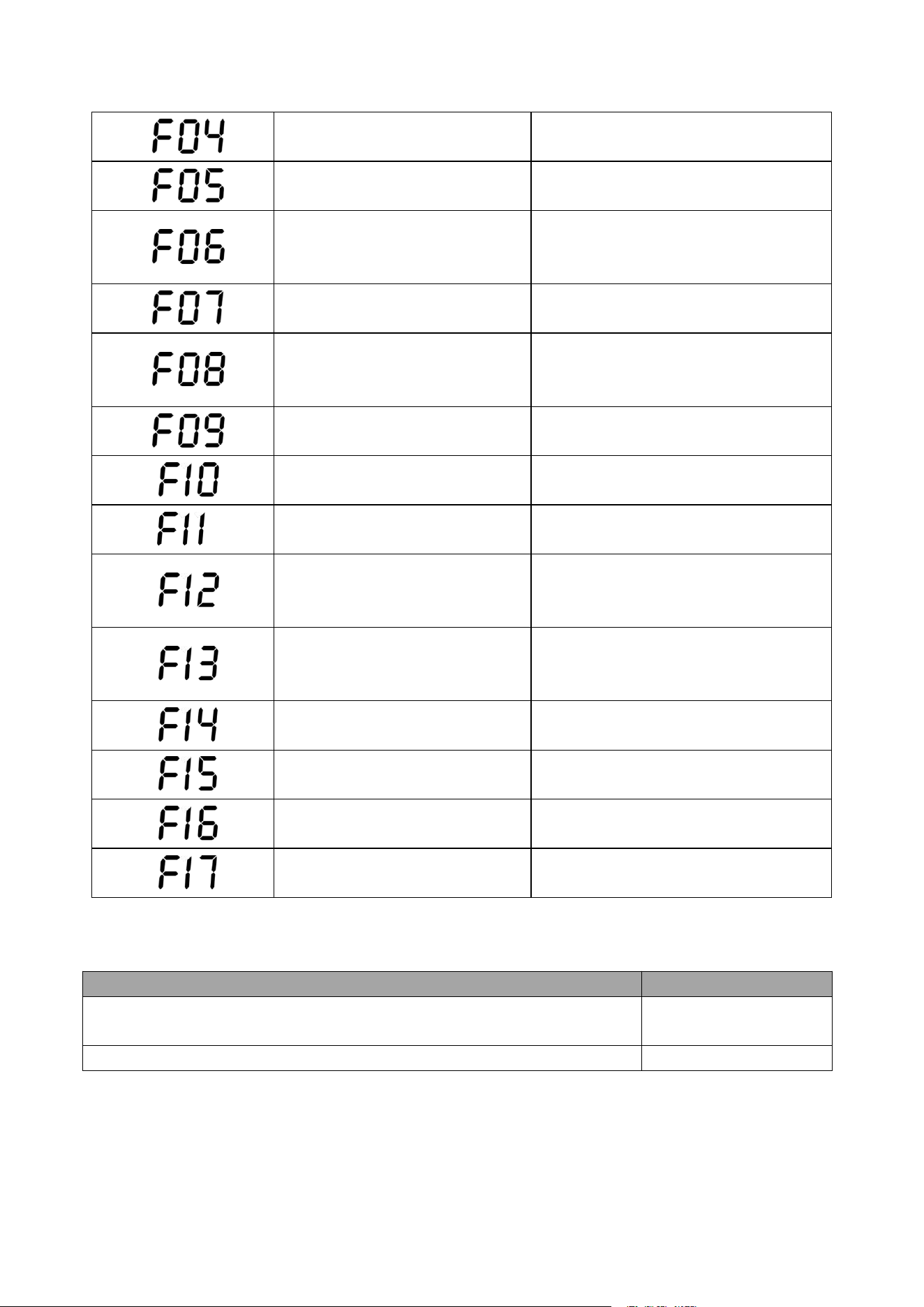
6.1 Failure Display and Troubleshooting
Fault name
Description
Troubleshooting
Remaining Discharge Time
Remaining Charge Time
Battery discharge - high
temperature warning (blink)
Place the device in a cool area until the
high temperature icon disappears.
Battery discharge - low temperature
warning (blink)
Place the device in a warm area until the
low temperature icon disappears.
Battery charging - high temperature
warning (blink)
Place the device in a cool area until the
high temperature icon disappears.
Battery charging - low temperature
warning (blink)
Place the device in a warm area until the
low temperature icon disappears.
AC input over/undervoltage or
over/under-frequency (blink)
Verify that the grid input voltage and
frequency are within the device's specified
range. If confirmed and fault still exists,
return the device for after-sales service.
AC output overload (blink)
Unplug the load and restart AC output. if
the fault still exists, return the device for
after-sales repair.
Type-C/USB output overload (blink)
Unplug the load and restart the device. if
the fault still exists, return the device for
after-sales repair.
Fan failure (blink)
Verify that the fan is functioning correctly.
Inverter BUS soft start fault
Restart the device. if the fault still exists,
return the device for after-sales repair.
Inverter output short circuit fault
Unplug the load and restart the device. if
the fault still exists, return the device for
after-sales repair.
Inverter BUS under voltage fault
Restart the device, if the fault still exists,
please contact the distributor.
19
Inverter BUS over voltage fault
Restart the device, if the fault still exists,
please contact the distributor.
Inverter BUS short circuit fault
Restart the device, if the fault still exists,
please contact the distributor.
Inverter output overcurrent fault
Remove the load and restart the device. If
the fault persists, return the device for
after-sales repair.
Inverter DC component too high
fault
Restart the device, if the fault still exists,
please contact the distributor.
Inverter over temperature fault
Verify that the inverter's operating
environment temperature is within the
specified range.
Inverter discharge over current fault
Restart the device, if the fault still exists,
please contact the distributor.
Inverter charging over current fault
Restart the device, if the fault still exists,
please contact the distributor.
Inverter current sensor fault
Restart the device, if the fault still exists,
please contact the distributor.
Inverter output overvoltage,
undervoltage, or over-frequency
fault
Check whether the power grid voltage and
frequency are within the working range of
the device.
AC load short-circuit
Unplug the load and restart the device. if
the fault still exists, return the device for
after-sales repair.
Inverter main relay fault
Restart the device, if the fault still exists,
please contact the distributor.
Inverter fan fault
Restart the device, if the fault still exists,
please contact the distributor.
Communication failure between DC
module and AC module
Restart the device, if the fault still exists,
please contact the distributor.
Communication failure between
BMS module and DC module
Restart the device, if the fault still exists,
please contact the distributor.
6.2 Maintenance
Maintenance item
Maintenance cycle
Clean housing and output ports (including DC output/AC socket/USB output
port) with a clean dust-free cloth.
Three months
The battery should be fully discharged and charged for one cycle.
Three months

20
7 Specification
Model
SP5000
Battery Input
Cell Type
LiFePO
4
Battery Capacity (Wh)
5120
Battery Input Nominal Voltage (V)
51.2
Battery Input Voltage Range (V)
40~60
Max. Charging Current (A)
80
Max. Discharging Current (A)
100
Life Cycles(@25℃, 0.5C Discharge,
DOD80%)
4000+
AC Input (Split Phase, L1-L2-N)
AC Charging Power (W)
3450
Nominal Voltage (Vac)
240
Voltage Range (Vac)
180~260
Nominal Frequency (Hz)
60
Max. AC Input Current (A)
16
Power Factor (@Max. Charging Power)
>0.99
AC Input (Single Phase, L1-N)
AC Charging Power (W)
1800
Nominal Voltage (Vac)
120
Voltage Range (Vac)
90~130
Nominal Frequency (Hz)
60
Max. AC Input Current (A)
16
Power Factor (@Max. Charging Power)
>0.99
AC Output (Split Phase, L1-L2-N)
Nominal AC Power (W)
5000
Surge Power (W)
9000
Nominal Grid Voltage (Vac)
240
Nominal Grid Frequency (Hz)
60
Max. AC Current (A)
21
THDv at Nominal Power (%)
<1.5
AC Output (Split Phase, L1-N / L2-N)
Nominal AC Power (W)
2500
Surge Power (W)
4500
Nominal Grid Voltage (Vac)
120
Nominal Grid Frequency (Hz)
60
Max. AC Current (A)
21
THDv at Nominal Power (%)
<1.5

21
Model
SP5000
DC Input (XT90)
Max. Input Power (W)
1000
Input Voltage Range (V)
12~80
Max. Input Current (A)
16
DC Output
USB-A (QC) (×2)
5V/3A, 9V/2A, 12V/1.5A
USB-TypeC (×2)
5V/3A, 9V/3A, 12V/3A, 20V/5A
Car Port (×1)
12V/10A
XT90 (×1)
12V/30A, 24V/25A, 36V/20A
Efficiency
Battery To AC, Max Efficiency (%)
93.0
AC To Battery, Max Efficiency (%)
92.0
Protection
AC output over current; AC output short circuit; AC charging
over current; AC output over/under voltage; AC output
over/under frequency; Inverter over temperature; AC
charging over/under voltage; Battery temperature high/low;
Battery over/under voltage
General Data
Dimensions (W/H/D) (mm)
450*538*352
(Inverter: 450*143*352; Battery: 450*152*352)
Weight (Kg)
65.2 (Inverter: 10.7; Battery1: 26.7; Battery2: 26.7)
LCD (mm)
80*64
Cooling Concept
Forced Air Cooling
Operating Temperature Range (℃)
0~40℃(charging), -20~+40℃(discharging)
Operating Relative Humidity (%)
10-90%
Ingress Protection
IP20
Noise(dB)
<65
Communication Interface
Wi-Fi / Bluetooth
Model
B2560
Battery Input
Cell Type Cell Type
LiFePO
4
Battery Capacity (Wh)
2560
Life Cycles(@25 ℃ , 0.5C Discharge,
DOD80%)
4000+
General Data
Dimensions (W/H/D) (mm)
450*152*352
Weight (Kg)
26.7
Operating Temperature Range (
℃
)
0~40℃(charging), -20~+40℃(discharging)
Operating Relative Humidity (%)
0~95%, Non condensation