Dorman Products, Inc. | Corporate Oce and Customer Service: 1-800-523-2492
©2020 No reproduction in whole or in part without prior written approval.
989-712_Instructions
REMOVAL/INSTALL INSTRUCTIONS:
IGNITION LOCK CYLINDER
989-712
ATTENTION: Refer to the appropriate shop manual for your vehicle to obtain specic service procedures for this part. If you do not have a service
manual or lack the skill to install this part, it is recommended that you seek the services of a qualied technician. Pay special attention to all
cautions and warnings included in the shop manual. Read and follow all instructions carefully. This product is only designed to function properly on
specic vehicle applications. Please verify that the vehicle requirements match the product specications and application notes for this part.
Disclaimer:
Even though every attempt is made to ensure this information is complete and accurate, it is impossible to account for all possible circumstances or situations. Please consult with a qualied auto
technician before attempting to perform any work you are not qualied to do. Automobiles can be hazardous to work on; be sure to take all necessary safety precautions. Failure to do so may result in
property damage or personal injury. Certain motor vehicle standards and performance requirements may apply to your motor vehicle (such as Federal Motor Vehicle Safety Standards by the National
Highway Trac Safety Administration). Be sure that your work is performed in accordance with such standards and that you do not disable any motor vehicle safety feature.
REMOVAL/INSTALL OF IGNITION LOCK CYLINDER (989-712)
Ford 2010–04, Lincoln 2009–04, Mercury 2009–04
GENERAL TECH TIPS:
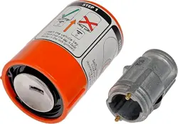
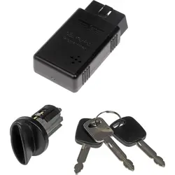
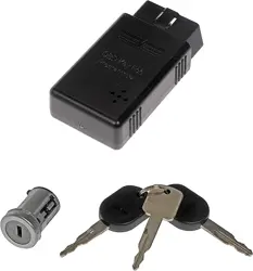
• This lock cylinder kit consists of an ignition lock with keys and a programming tool. There are 3 keys provided in this kit; 2 transponder security
keys and 1 non-transponder key. The 2 transponder keys will need to be programmed to your car to avoid a no-start condition.
PLEASE WEAR
SAFETY GLASSES!
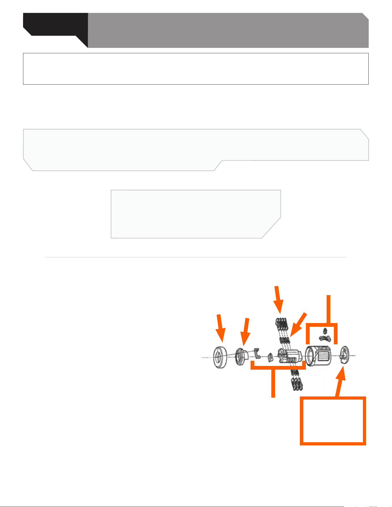
NOTE: This part comes with a retaining ring clip. This
clip is not needed for vehicles 2008 and newer.
SERVICE
CAP
COVER
TUMBLERS
TUMBLER
SPRINGS
RETAINING RING
(OPTIONAL)
NOT REQUIRED
FOR MODELS
BEGINNING 2008
CYLINDER
SUB-ASSEMBLY
HOUSING
SUB-ASSEMBLY
Dorman Products, Inc. | Corporate Oce and Customer Service: 1-800-523-2492
©2020 No reproduction in whole or in part without prior written approval.
989-712_Instructions
REMOVAL/INSTALL INSTRUCTIONS:
IGNITION LOCK CYLINDER
989-712
ATTENTION: Refer to the appropriate shop manual for your vehicle to obtain specic service procedures for this part. If you do not have a service
manual or lack the skill to install this part, it is recommended that you seek the services of a qualied technician. Pay special attention to all
cautions and warnings included in the shop manual. Read and follow all instructions carefully. This product is only designed to function properly on
specic vehicle applications. Please verify that the vehicle requirements match the product specications and application notes for this part.
Disclaimer:
Even though every attempt is made to ensure this information is complete and accurate, it is impossible to account for all possible circumstances or situations. Please consult with a qualied auto
technician before attempting to perform any work you are not qualied to do. Automobiles can be hazardous to work on; be sure to take all necessary safety precautions. Failure to do so may result in
property damage or personal injury. Certain motor vehicle standards and performance requirements may apply to your motor vehicle (such as Federal Motor Vehicle Safety Standards by the National
Highway Trac Safety Administration). Be sure that your work is performed in accordance with such standards and that you do not disable any motor vehicle safety feature.
Removal Instructions
STEP 1: Disconnect the battery.
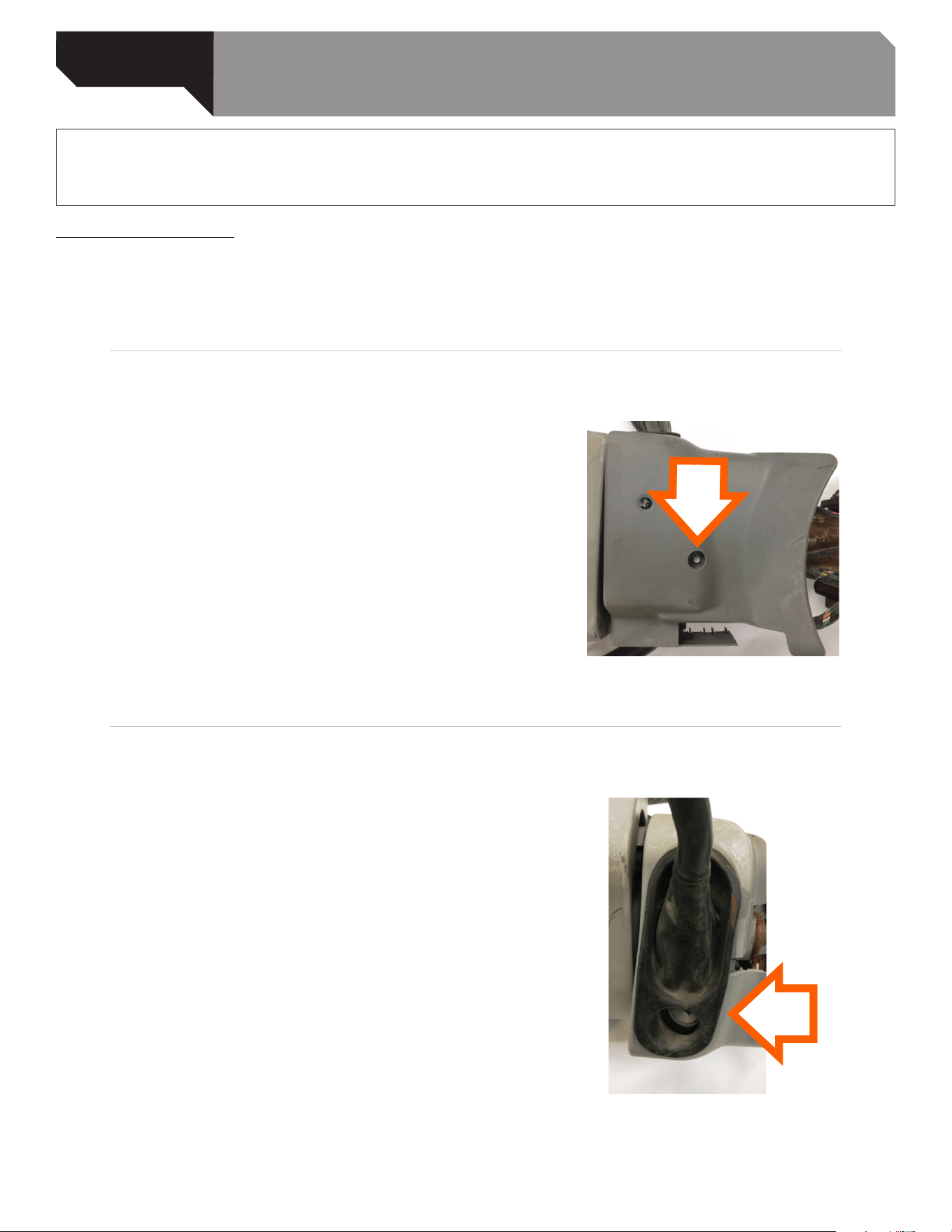
STEP 2: Remove the bottom column shroud screw
and remove shroud. NOTE: Shroud removal may vary
among models.
STEP 3: If equipped, gently pry the shifter lever dust
cover away from the column.
Dorman Products, Inc. | Corporate Oce and Customer Service: 1-800-523-2492
©2020 No reproduction in whole or in part without prior written approval.
989-712_Instructions
REMOVAL/INSTALL INSTRUCTIONS:
IGNITION LOCK CYLINDER
989-712
ATTENTION: Refer to the appropriate shop manual for your vehicle to obtain specic service procedures for this part. If you do not have a service
manual or lack the skill to install this part, it is recommended that you seek the services of a qualied technician. Pay special attention to all
cautions and warnings included in the shop manual. Read and follow all instructions carefully. This product is only designed to function properly on
specic vehicle applications. Please verify that the vehicle requirements match the product specications and application notes for this part.
Disclaimer:
Even though every attempt is made to ensure this information is complete and accurate, it is impossible to account for all possible circumstances or situations. Please consult with a qualied auto
technician before attempting to perform any work you are not qualied to do. Automobiles can be hazardous to work on; be sure to take all necessary safety precautions. Failure to do so may result in
property damage or personal injury. Certain motor vehicle standards and performance requirements may apply to your motor vehicle (such as Federal Motor Vehicle Safety Standards by the National
Highway Trac Safety Administration). Be sure that your work is performed in accordance with such standards and that you do not disable any motor vehicle safety feature.
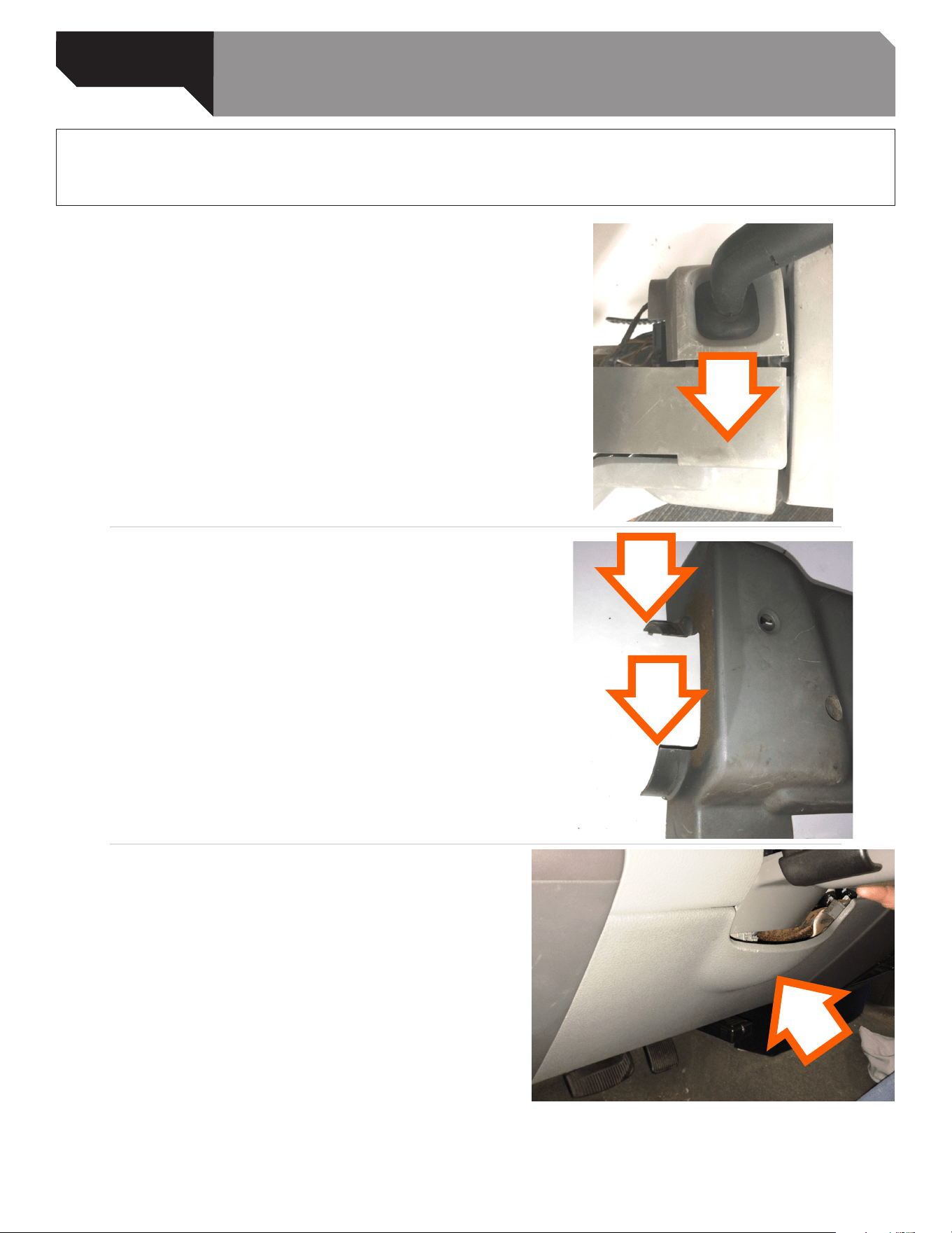
STEP 4: Gently pry the lower shroud apart from
upper shroud and remove from the column. The
upper shroud will remain on column, do not remove.
STEP 4a: The lower shroud end anges may be
caught in steering wheel. Gently pull down and
away from behind the steering wheel to assist in the
removal. The steering wheel may need to be rotated
to help ease the removal. NOTE: The column shrouds
may appear dierent as the conguration may vary
among models and years.
STEP 5: Remove the lower dash trim panel for ease of
shroud removal, if needed.
Dorman Products, Inc. | Corporate Oce and Customer Service: 1-800-523-2492
©2020 No reproduction in whole or in part without prior written approval.
989-712_Instructions
REMOVAL/INSTALL INSTRUCTIONS:
IGNITION LOCK CYLINDER
989-712
ATTENTION: Refer to the appropriate shop manual for your vehicle to obtain specic service procedures for this part. If you do not have a service
manual or lack the skill to install this part, it is recommended that you seek the services of a qualied technician. Pay special attention to all
cautions and warnings included in the shop manual. Read and follow all instructions carefully. This product is only designed to function properly on
specic vehicle applications. Please verify that the vehicle requirements match the product specications and application notes for this part.
Disclaimer:
Even though every attempt is made to ensure this information is complete and accurate, it is impossible to account for all possible circumstances or situations. Please consult with a qualied auto
technician before attempting to perform any work you are not qualied to do. Automobiles can be hazardous to work on; be sure to take all necessary safety precautions. Failure to do so may result in
property damage or personal injury. Certain motor vehicle standards and performance requirements may apply to your motor vehicle (such as Federal Motor Vehicle Safety Standards by the National
Highway Trac Safety Administration). Be sure that your work is performed in accordance with such standards and that you do not disable any motor vehicle safety feature.
STEP 6: Some models may require the steering wheel to be rotated to help aid in the shroud removal.
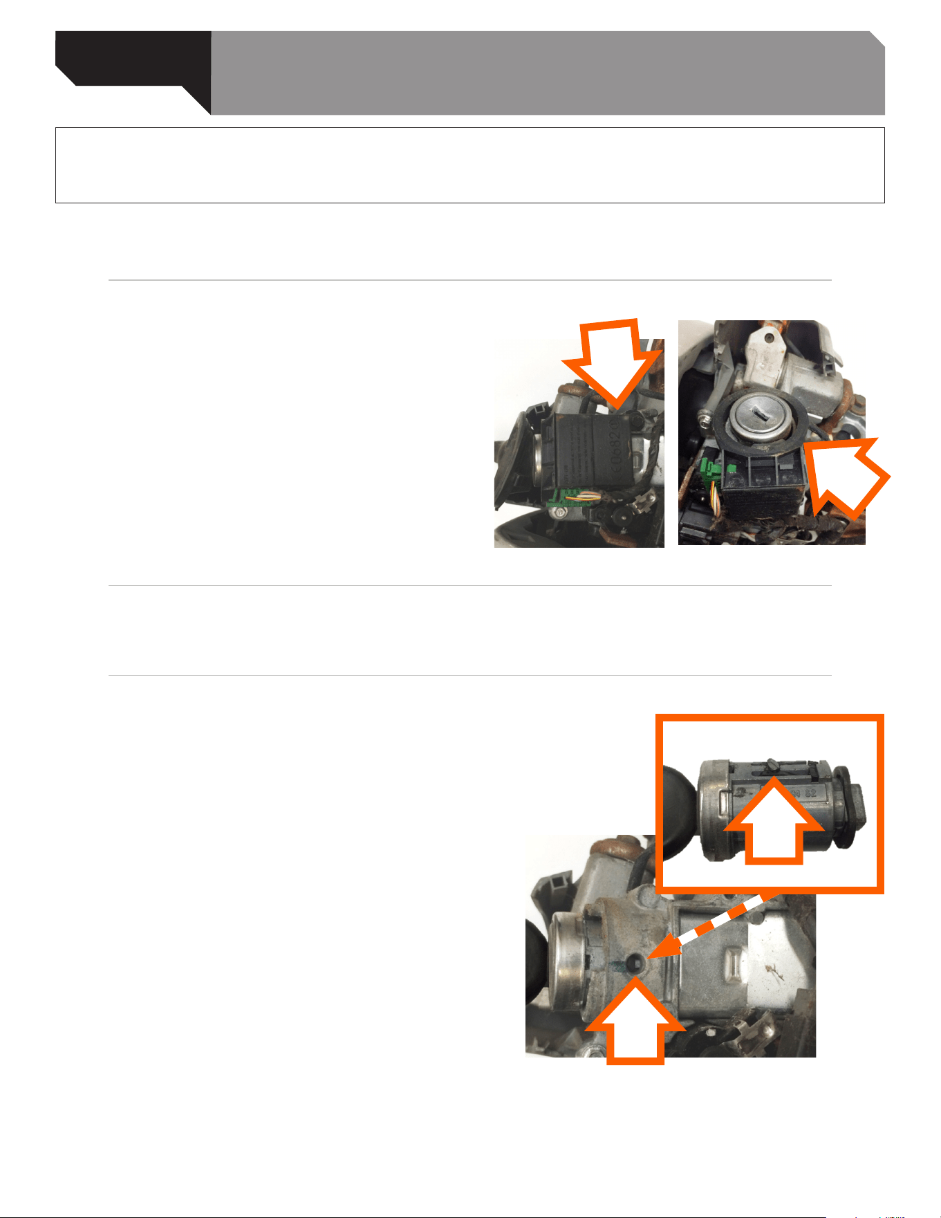
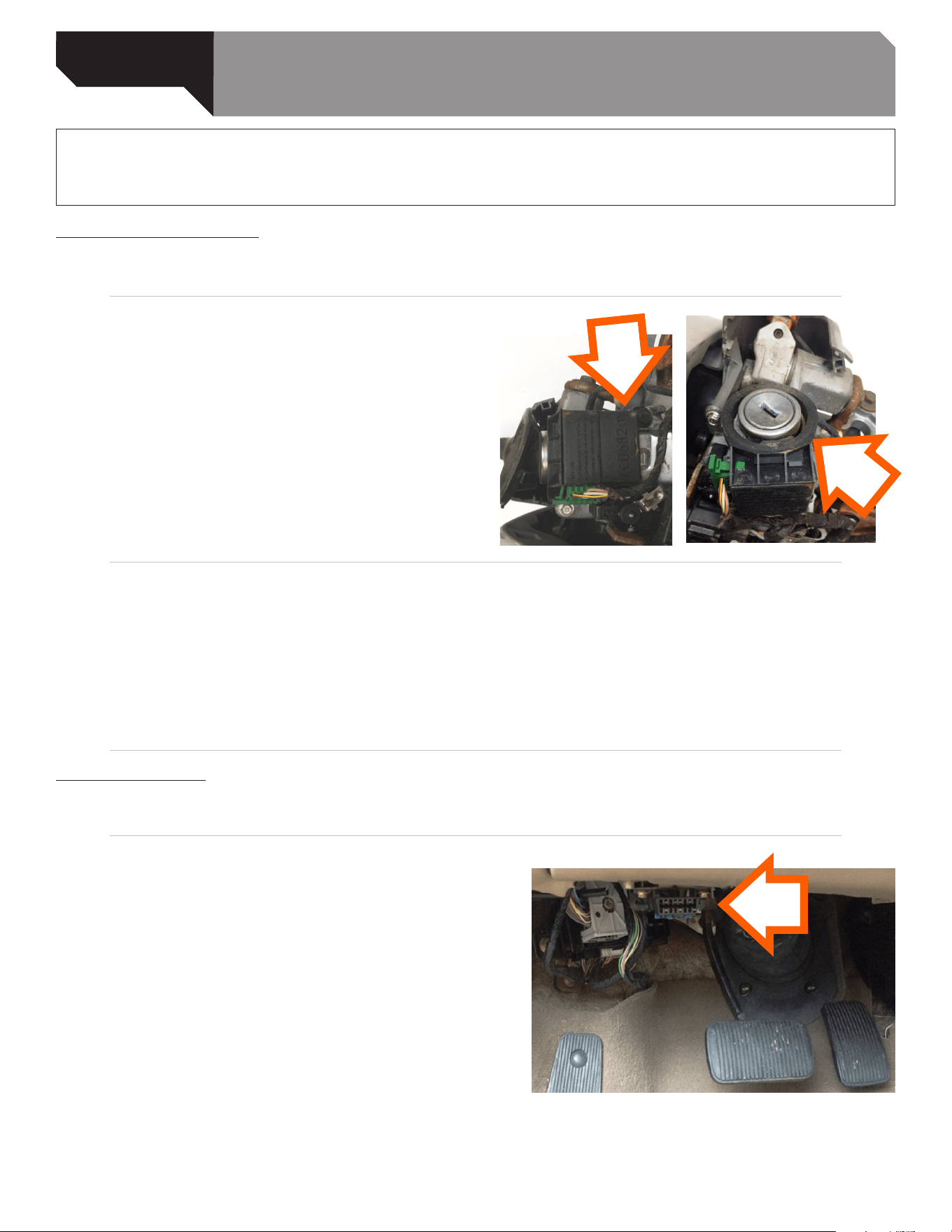
STEP 7: Remove the security receiver ring from the
lock housing by removing the retaining screw.
STEP 8: Rotate the lock cylinder to the run position.
STEP 9: Using a small screwdriver or suitable tool,
depress the ignition lock release tab and pull the
ignition lock from the column.
Dorman Products, Inc. | Corporate Oce and Customer Service: 1-800-523-2492
©2020 No reproduction in whole or in part without prior written approval.
989-712_Instructions
REMOVAL/INSTALL INSTRUCTIONS:
IGNITION LOCK CYLINDER
989-712
ATTENTION: Refer to the appropriate shop manual for your vehicle to obtain specic service procedures for this part. If you do not have a service
manual or lack the skill to install this part, it is recommended that you seek the services of a qualied technician. Pay special attention to all
cautions and warnings included in the shop manual. Read and follow all instructions carefully. This product is only designed to function properly on
specic vehicle applications. Please verify that the vehicle requirements match the product specications and application notes for this part.
Disclaimer:
Even though every attempt is made to ensure this information is complete and accurate, it is impossible to account for all possible circumstances or situations. Please consult with a qualied auto
technician before attempting to perform any work you are not qualied to do. Automobiles can be hazardous to work on; be sure to take all necessary safety precautions. Failure to do so may result in
property damage or personal injury. Certain motor vehicle standards and performance requirements may apply to your motor vehicle (such as Federal Motor Vehicle Safety Standards by the National
Highway Trac Safety Administration). Be sure that your work is performed in accordance with such standards and that you do not disable any motor vehicle safety feature.
Installation Instructions
STEP 1: Install the new lock into the column.
STEP 2: Reinstall the security receiver ring
and the retaining screw.
STEP 3: If equipped, reinstall the shifter lever dust cover.
STEP 4: Reinstall the lower shroud and the retaining screw.
STEP 5: Verify there is free rotation of new lock cylinder.
STEP 6: Reconnect negative battery cable and program new keys using the following key
programming instructions.
Key Programming
STEP 1: Remove all keys from the ring and separate them from each other.
STEP 2: Plug the programmer into the OBD2 port.
(The OBD2 port is located under the dash by brake
pedal). Wait for a beep.
Dorman Products, Inc. | Corporate Oce and Customer Service: 1-800-523-2492
©2020 No reproduction in whole or in part without prior written approval.
989-712_Instructions
REMOVAL/INSTALL INSTRUCTIONS:
IGNITION LOCK CYLINDER
989-712
ATTENTION: Refer to the appropriate shop manual for your vehicle to obtain specic service procedures for this part. If you do not have a service
manual or lack the skill to install this part, it is recommended that you seek the services of a qualied technician. Pay special attention to all
cautions and warnings included in the shop manual. Read and follow all instructions carefully. This product is only designed to function properly on
specic vehicle applications. Please verify that the vehicle requirements match the product specications and application notes for this part.
Disclaimer:
Even though every attempt is made to ensure this information is complete and accurate, it is impossible to account for all possible circumstances or situations. Please consult with a qualied auto
technician before attempting to perform any work you are not qualied to do. Automobiles can be hazardous to work on; be sure to take all necessary safety precautions. Failure to do so may result in
property damage or personal injury. Certain motor vehicle standards and performance requirements may apply to your motor vehicle (such as Federal Motor Vehicle Safety Standards by the National
Highway Trac Safety Administration). Be sure that your work is performed in accordance with such standards and that you do not disable any motor vehicle safety feature.
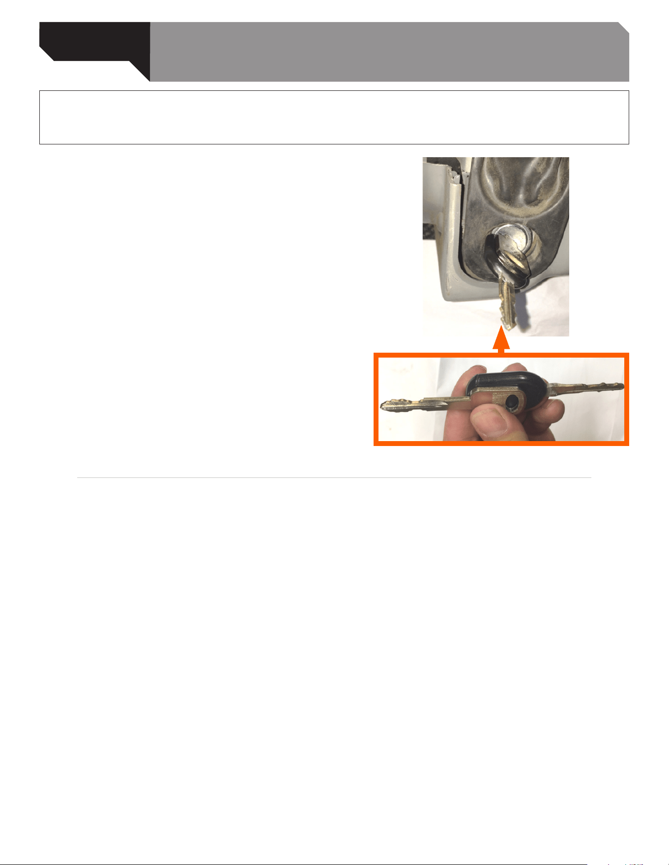
STEP 3: Insert the non-transponder key into the new
lock while simultaneously holding the original key up
against the non-transponder key and the lock in the
orientation shown. Turn the key to the ON position
without starting, and wait for programmer to beep.
NOTE: Do not hold original key next to the column
or ignition after Step 3, as this will cause
a programming failure.
STEP 4: Insert the rst new transponder key. Turn the key to the ON position but do not start vehicle. Wait
for the programmer to beep twice.
STEP 5: The programmer will begin a 10 minute security access wait. The programmer LED will ash.
STEP 6: The programmer will beep twice when security access is obtained.
STEP 7: Cycle the rst new key from ON to OFF back to ON.
STEP 8: Wait for the programmer to beep once, then the turn key to the o position and remove.
Dorman Products, Inc. | Corporate Oce and Customer Service: 1-800-523-2492
©2020 No reproduction in whole or in part without prior written approval.
989-712_Instructions
REMOVAL/INSTALL INSTRUCTIONS:
IGNITION LOCK CYLINDER
989-712
ATTENTION: Refer to the appropriate shop manual for your vehicle to obtain specic service procedures for this part. If you do not have a service
manual or lack the skill to install this part, it is recommended that you seek the services of a qualied technician. Pay special attention to all
cautions and warnings included in the shop manual. Read and follow all instructions carefully. This product is only designed to function properly on
specic vehicle applications. Please verify that the vehicle requirements match the product specications and application notes for this part.
Disclaimer:
Even though every attempt is made to ensure this information is complete and accurate, it is impossible to account for all possible circumstances or situations. Please consult with a qualied auto
technician before attempting to perform any work you are not qualied to do. Automobiles can be hazardous to work on; be sure to take all necessary safety precautions. Failure to do so may result in
property damage or personal injury. Certain motor vehicle standards and performance requirements may apply to your motor vehicle (such as Federal Motor Vehicle Safety Standards by the National
Highway Trac Safety Administration). Be sure that your work is performed in accordance with such standards and that you do not disable any motor vehicle safety feature.
Still need help?
Please call our Technical Support team for assistance
from our team of certied automotive experts.
1-800-523-2492
STEP 9: Insert the second new transponder key and turn to ON position.
STEP 10: The programmer will beep 3 times when programming is complete.
STEP 11: Both transponder keys are now programmed; the non-transponder key can be discarded.