
DTS27 (Direct Meter) Operating
Manual
Shenzhen Star Instrument Co., Ltd.

Caution: The user is cautioned that changes or modifications not expressly approved by the party
responsible for compliance could void the user's authority to operate the equipment.
This device complies with Part 15 of the FCC Rules. Operation is subject to the following two conditions:
(1) this device may not cause harmful interference, and (2) this device must accept any interference
received, including interference that may cause undesired operation.
NOTE: This equipment has been tested and found to comply with the limits for a Class B digital device,
pursuant to Part 15 of the FCC Rules. These limits are designed to provide reasonable protection against
harmful interference in a residential installation. This equipment generates, uses and can radiate radio
frequency energy and, if not installed and used in accordance with the instructions, may cause harmful
interference to radio communications. However, there is no guarantee that interference will not occur in a
particular installation.
If this equipment does cause harmful interference to radio or television reception, which can be
determined by turning the equipment off and on, the user is encouraged to try to correct the interference
by one or more of the following measures:
Reorient or relocate the receiving antenna.
Increase the separation between the equipment and receiver.
Connect the equipment into an outlet on a circuit different from that to which the receiver is
connected.
Consult the dealer or an experienced radio/TV technician for help.
FCC Radiation Exposure Statement:
This equipment complies with FCC radiation exposure limits set forth for an uncontrolled environment.
This transmitter must not be co-located or operating in conjunction with any other antenna or transmitter.
This equipment should be installed and operated with a minimum distance of 20cm between the radiator
and your body.

Revision History
Revision Date
Version Record
Description of Major Changes
20241218
Initial Draft
20250306
Adjusted Format, Header

Table of Contents
Three-phase Direct-connect Meter DTS27 (Direct Meter) Operating Manual .. 1
Shenzhen Star Instrument Co., Ltd. ...........................................................1
Revision History .........................................................................................3
Table of Contents .......................................................................................4
1 Electricity Meter Introduction .........................................................................6
1.1 Technical Parameters .......................................................................... 6
1.2 Electrical Performance .........................................................................6
1.3 Insulation Performance ........................................................................ 6
1.4 Operating Environment ........................................................................ 7
1.5 Communication Interface ..................................................................... 7
1.6 Standards Compliance .........................................................................8
2 Structure Description .....................................................................................8
2.1 Appearance ..........................................................................................8
2.2 Meter Structure Dimensions ................................................................ 9
2.3 Wiring Diagram .................................................................................. 10
Electricity Meter Introduction ..........................................................................10
2.4 Basic Energy ......................................................................................10
2.5 Per-phase Energy (Only for Poly-phase Meters) ............................... 11
2.1 Demand ............................................................................................. 12
2.2 Maximum Demand .............................................................................13
2.3 Demand Storage and Clearance ....................................................... 14
3 Instantaneous Values ..................................................................................14
3.1 Basic Instantaneous Values ...............................................................15
3.2 Other Instantaneous Values ...............................................................16
4 Clock (Only for Meters with Battery) ........................................................... 16
4.1 Clock Accuracy .................................................................................. 17
5 Human Machine Interface ........................................................................... 17
5.1 Display Button ....................................................................................17
5.2 Keypad (Optional) ..............................................................................17
5.3 Backlight Indicator ............................................................................. 18
5.4 Display ............................................................................................... 18
5.4.1 LCD Display Content Description ............................................. 18
5.4.2 Auto-scroll Display .................................................................... 20
5.4.3 Button-triggered Display ........................................................... 21
5.4.4 Popup Display .......................................................................... 21
5.4.5 Power Loss Display .................................................................. 21
5.5 LED Indicators ................................................................................... 22
5.5.1 Pulse Indicator ..........................................................................22
5.5.2 Alarm Indicator ..........................................................................22
5.5.3 Credit/Power Indicator .............................................................. 23
6 Load Management ...................................................................................... 23

6.1 Load Control ...................................................................................... 23
7 Relay Control .............................................................................................. 23
7.1 Common Trip Reasons ...................................................................... 24
8 Event Logging ............................................................................................. 24
8.1 Event Detection ................................................................................. 24
9 Time-of-Use Tariff ........................................................................................ 25
10 Tiered Energy (Only for Prepayment Meters) ............................................25
11 Tariff (Only for Prepayment Meters) .......................................................... 25
11.1 Time-of-Use Tariff ............................................................................. 25
11.2 Tiered Tariff ...................................................................................... 25
12 Payment Mode (Only for Prepayment Meters) ..........................................25
12.1 Prepayment Mode ............................................................................26
12.2 Postpayment Mode .......................................................................... 26
12.3 Payment Mode Switching ................................................................ 26
13 Prepayment (Only for Prepayment Meters) ...............................................26
13.1 TOKEN Credit .................................................................................. 27
13.1.1 Purchasing Electricity ............................................................. 27
13.1.2 Loading Electricity .................................................................. 27
13.2 Emergency Credit ............................................................................ 28
13.3 Friendly Credit ................................................................................. 28
13.3.1 Friendly Day ........................................................................... 28
13.3.2 Friendly Period ....................................................................... 28
13.4 Low Credit Alarm Function ...............................................................28

1 Electricity Meter Introduction
1.1 Technical Parameters
Rated Voltage (Un)
3×220/380V
Rated Current (In)
5A
Maximum Current (Imax)
100A
Starting Current
Active: 0.4%In
Reactive: 0.5%In
Rated Frequency
50Hz
Accuracy Class
Active: Class 1
Reactive: Class 2
Pulse Constant
1000 imp/kWh
1000 imp/kvarh
1.2 Electrical Performance
Operating Voltage Range
0.7Un - 1.2Un
Operating Frequency Range
Rated Frequency
±5%
Voltage Circuit Consumption
(Non-communication)
Not more than 2W,
10VA
Voltage Circuit Consumption (During
communication)
Not more than 5W,
25VA
Current Circuit Consumption
Not more than
2.5VA
1.3 Insulation Performance
No.
Item Name
IEC62053-21 Requirement
1
Impulse
Voltage
Class II insulation, 6KV
2
AC Voltage
Current circuit to earth (Class II insulation),

4KV
Between auxiliary terminals, 2KV
1.4 Operating Environment
No.
Item Name
IEC62053-21 Requirement
1
Temperature
Operating temperature range: -25
℃~
60
℃
Operating limit temperature range: -40
℃~
70
℃
Storage and transportation limit temperature
range: -40
℃~
80
℃
2
Humidity
Annual average: ≤75
%
30 days in a year: ≤95
%
Other time: ≤85
%
1.5 Communication Interface
Non-modulated Infrared
Interface
Type
Serial bidirectional
communication interface
Baud
Rate
9600bps 8N1
RS485 Interface
Type
Serial bidirectional
communication interface
Baud
Rate
9600bps 8N1
Communication Module
Interface
Type
Serial bidirectional
communication interface
Baud
Rate
9600bps 8N1

1.6 Standards Compliance
Note: The following standards are for reference. The actual standards
implemented are subject to the technical parameter table.
IEC62052-11 Electricity metering equipment(AC)-General
requirements,tests and test conditions- Part11:Metering
equipment
IEC62053-21 Electricity metering
equipment(a.c.)-Particular requirements-Part21:Static
meters for active energy(classes 1 and 2)
IEC62055-31 Electricity metering -Payment
systems-Part31:Particular requirements Static payment
meters for active energy(class 1 and 2)
IEC62056-21 Electricity metering - Data exchange for
meter reading, tariff and load control -Part 21: Direct local
data exchange
IEC62056-46 Electricity metering --Data exchange for
meter reading,tariff and load control --Part 46:Data link
layer using HDLC protocol
IEC62056-53 Electricity metering --Data exchange for
meter reading,tariff and load control --Part 53:COSEM
application layer
IEC62056-61 Electricity metering --Data exchange for
meterreading, tariff and load control --Part 61:Object
identification system (OBIS)
IEC62056-62 Electricity metering --Data exchange for
meterreading, tariff and load control --Part 62:Interface
classes
2 Structure Description
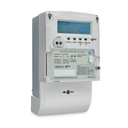
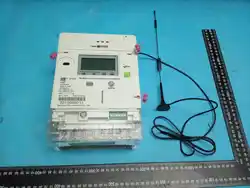
2.1 Appearance
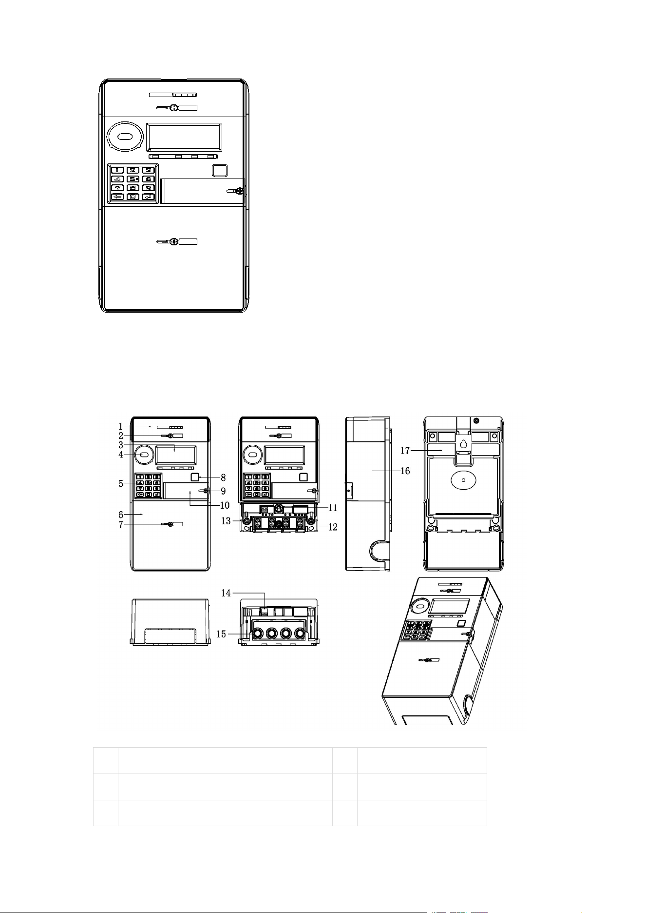
2.2 Meter Structure Dimensions
01
Module Box
02
Module Box Seal
03
LCD Display Window
04
Optical Port
05
Button
06
Terminal Cover
07
Terminal Cover Seal
08
Display Button
09
Battery Cover Seal
10
Battery Cover
11
Terminal Cover Open Detection
12
Wire Clamp Screw
13
Upper Cover Seal
14
Pulse Terminal
15
Current Terminal
16
Upper Cover
17
Bottom Case
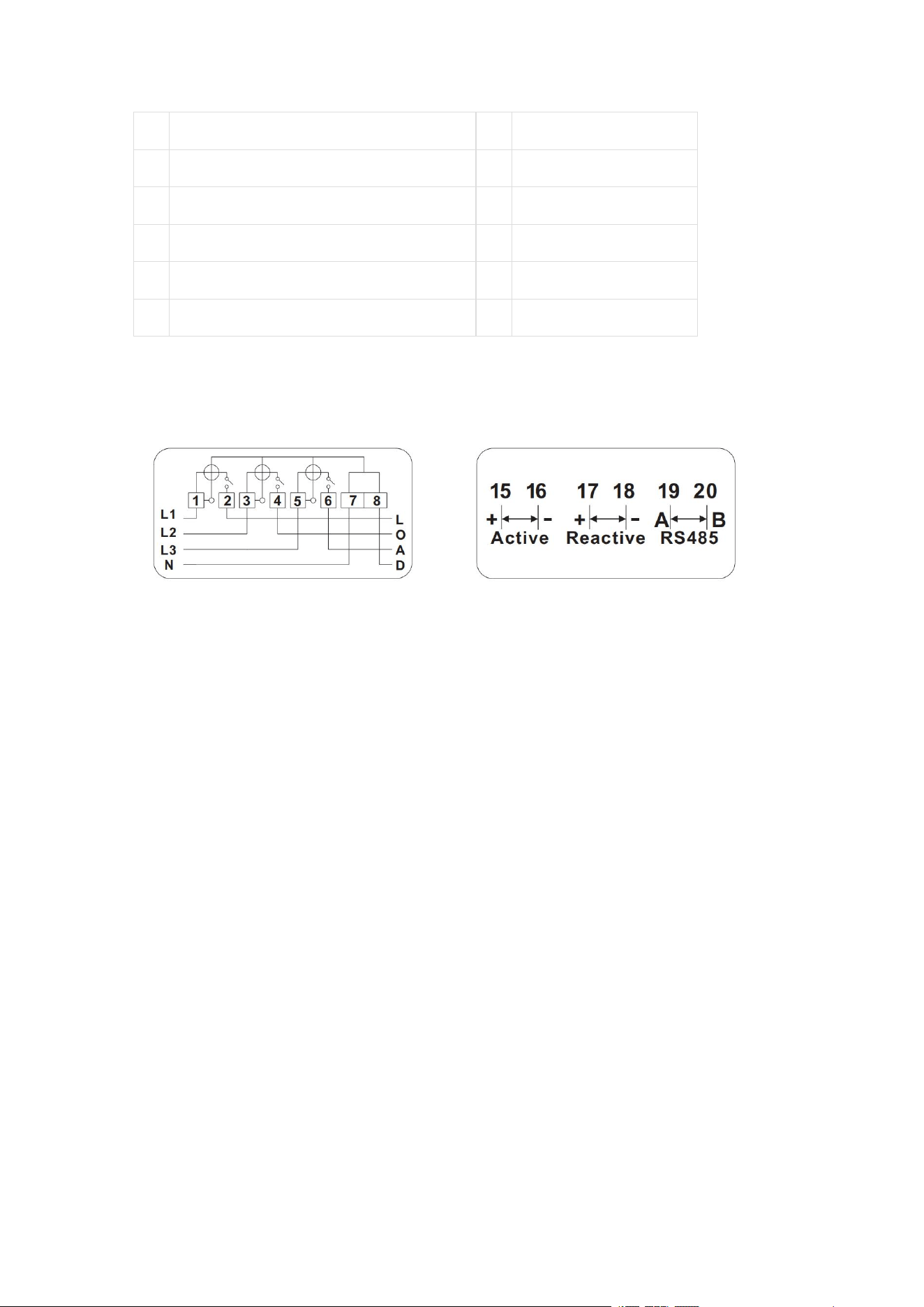
2.3 Wiring Diagram
Electricity Meter Introduction
The meter supports various energy measurement functions. Specific
supported energy objects are listed below.
Note:
1. In the object identifiers (OBIS codes) in the tables of this chapter, T
is the tariff identifier:
T = 0 indicates total energy;
T = 1~N indicates energy for each tariff; the specific
number of supported tariffs N is detailed in the technical
parameter table.
2. Whether the product supports reactive energy, apparent energy,
and per-phase energy functions is subject to the specific
requirements in the technical parameter table.
2.4 Basic Energy

The basic energy measurement objects supported by the meter and
their unit dimensions are listed in the following table:
Energy
Category
Energy Object
Object
Identifier
Note
Active Energy
Total and tariff forward active
energy
1-0:1.8.T.255
Total and tariff reverse active
energy
1-0:2.8.T.255
Total and tariff total active
energy
1-0:15.8.T.255
Total and tariff net active energy
1-0:16.8.T.255
Reactive
Energy
Total and tariff forward reactive
energy
1-0:3.8.T.255
Total and tariff reverse reactive
energy
1-0:4.8.T.255
Total and tariff quadrant 1
reactive energy
1-0:5.8.T.255
Total and tariff quadrant 2
reactive energy
1-0:6.8.T.255
Total and tariff quadrant 3
reactive energy
1-0:7.8.T.255
Total and tariff quadrant 4
reactive energy
1-0:8.8.T.255
Apparent
Energy
Total and tariff forward apparent
energy
1-0:9.8.T.255
Total and tariff reverse apparent
energy
1-0:10.8.T.255
Note
: T is the tariff identifier.
2.5 Per-phase Energy (Only for Poly-phase
Meters)
The per-phase energy measurement objects supported by the meter
and their unit dimensions are listed in the following table:

Energy
Category
Energy Object
Object Identifier
Active Energy
A(B/C) phase forward active
energy
1-0:21(41/61).8.0.255
A(B/C) phase reverse active
energy
1-0:22(42/62).8.0.255
A(B/C) phase total active
energy
1-0:35(55/75).8.0.255
A(B/C) phase net active
energy
1-0:36(56/76).8.0.255
Reactive
Energy
A(B/C) phase forward
reactive energy
1-0:23(43/63).8.0.255
A(B/C) phase reverse
reactive energy
1-0:24(44/64).8.0.255
A(B/C) phase quadrant 1
reactive energy
1-0:25(45/65).8.0.255
A(B/C) phase quadrant 2
reactive energy
1-0:26(46/66).8.0.255
A(B/C) phase quadrant 3
reactive energy
1-0:27(47/67).8.0.255
A(B/C) phase quadrant 4
reactive energy
1-0:28(48/68).8.0.255
Apparent
Energy
A(B/C) phase forward
apparent energy
1-0:29(49/69).8.0.255
A(B/C) phase reverse
apparent energy
1-0:30(50/70).8.0.255
2.1 Demand
The demand objects supported by the meter are listed in the following
table.
Note:
1. In the object identifiers (OBIS codes) in the tables of this chapter, T
is the tariff identifier:

T = 0 indicates total energy;
T = 1~N indicates energy for each tariff; the specific
number of supported tariffs N is detailed in the technical
parameter table.
2. Whether the product supports reactive demand and apparent
demand functions is subject to the specific requirements in the
technical parameter table.
Demand
Category
Demand Object
Object
Identifier
Note
Active Demand
Total and tariff forward active
demand
1-0:1.4.T.255
Total and tariff reverse active
demand
1-0:2.4.T.255
Reactive
Demand
Total and tariff forward reactive
demand
1-0:3.4.T.255
Total and tariff reverse reactive
demand
1-0:4.4.T.255
Total and tariff quadrant 1
reactive demand
1-0:5.4.T.255
Total and tariff quadrant 2
reactive demand
1-0:6.4.T.255
Total and tariff quadrant 3
reactive demand
1-0:7.4.T.255
Total and tariff quadrant 4
reactive demand
1-0:8.4.T.255
Apparent
Demand
Total and tariff forward apparent
demand
1-0:9.4.T.255
Total and tariff reverse apparent
demand
1-0:10.4.T.255
Note
: T is the tariff identifier.
2.2 Maximum Demand
The maximum demand objects supported by the meter and their unit
dimensions are listed in the following table:

Demand
Category
Demand Object
Object
Identifier
Note
Active
Demand
Total and tariff forward active
maximum demand
1-0:1.6.T.255
Total and tariff reverse active
maximum demand
1-0:2.6.T.255
Reactive
Demand
Total and tariff forward reactive
maximum demand
1-0:3.6.T.255
Total and tariff reverse reactive
maximum demand
1-0:4.6.T.255
Total and tariff quadrant 1
reactive maximum demand
1-0:5.6.T.255
Total and tariff quadrant 2
reactive maximum demand
1-0:6.6.T.255
Total and tariff quadrant 3
reactive maximum demand
1-0:7.6.T.255
Total and tariff quadrant 4
reactive maximum demand
1-0:8.6.T.255
Apparent
Demand
Total and tariff forward apparent
maximum demand
1-0:9.6.T.255
Total and tariff reverse apparent
maximum demand
1-0:10.6.T.255
Note
: T is the tariff identifier.
2.3 Demand Storage and Clearance
When the meter reaches the set monthly storage (monthly settlement)
time, the monthly maximum demand is automatically stored and then
cleared to restart calculation.
3 Instantaneous Values
The meter supports real-time measurement of instantaneous values.
Note:

1. Whether the product supports reactive power and apparent power
functions is subject to the specific requirements in the technical
parameter table.
3.1 Basic Instantaneous Values
The related objects and their unit dimensions are listed in the
following table:
Category
Object
Object Identifier
Voltage
A phase voltage
1-0:32.7.0.255
B phase voltage
1-0:52.7.0.255
C phase voltage
1-0:72.7.0.255
Current
A phase current
1-0:31.7.0.255
B phase current
1-0:51.7.0.255
C phase current
1-0:71.7.0.255
Combined phase current
1-0:90.7.0.255
N line current
1-0:91.7.0.255
Active
Power
Combined phase (A/B/C
phase) forward active power
1-0:1(21/41/61).7.0.255
Combined phase (A/B/C
phase) reverse active power
1-0:2(22/42/62).7.0.255
Combined phase (A/B/C
phase) total active power
1-0:15(35/55/75).7.0.255
Reactive
Power
Combined phase (A/B/C
phase) forward reactive
power
1-0:3(23/43/63).7.0.255
Combined phase (A/B/C
phase) reverse reactive
power
1-0:4(24/44/64).7.0.255
Combined phase (A/B/C
phase) quadrant 1 reactive
power
1-0:5(25/45/65).7.0.255
Combined phase (A/B/C
phase) quadrant 2 reactive
1-0:6(26/46/66).7.0.255

power
Combined phase (A/B/C
phase) quadrant 3 reactive
power
1-0:7(27/47/67).7.0.255
Combined phase (A/B/C
phase) quadrant 4 reactive
power
1-0:8(28/48/68).7.0.255
Apparent
Power
Combined phase (A/B/C
phase) forward apparent
power
1-0:9(29/49/69).7.0.255
Combined phase (A/B/C
phase) reverse apparent
power
1-0:10(30/50/70).7.0.255
Power
Factor
Combined phase forward
power factor
1-0:13.7.0.255
A phase power factor
1-0:33.7.0.255
B phase power factor
1-0:53.7.0.255
C phase power factor
1-0:73.7.0.255
Combined phase reverse
power factor
1-0:84.7.0.255
Grid
Frequency
Grid frequency
1-0:14.7.0.255
3.2 Other Instantaneous Values
The related objects and their unit dimensions are listed in the
following table:
Category
Object
Object Identifier
Temperature
Meter temperature
0-0:96.9.0.255
Battery Voltage
External battery voltage
0-0:96.6.3.255
4 Clock (Only for Meters with
Battery)

4.1 Clock Accuracy
Within the temperature range of -25~+60℃: Clock accuracy ≤
±1s/d;
At reference temperature (23℃): Clock accuracy ≤ ±0.5s/d;
When the electricity meter is powered off, the backup battery is
activated to maintain clock accuracy.
5 Human Machine Interface
5.1 Display Button
The electricity meter supports the display button function.
1.
Button-triggered Display
When the meter is in auto-scroll display mode, briefly press the
display button to enter button-triggered display mode;
In button-triggered display mode, briefly press the display
button to page through the display data;
In button-triggered display mode, if no button operation occurs
for a set period (configurable, default value refer to technical
parameter table), the meter automatically returns to auto-scroll
display mode.
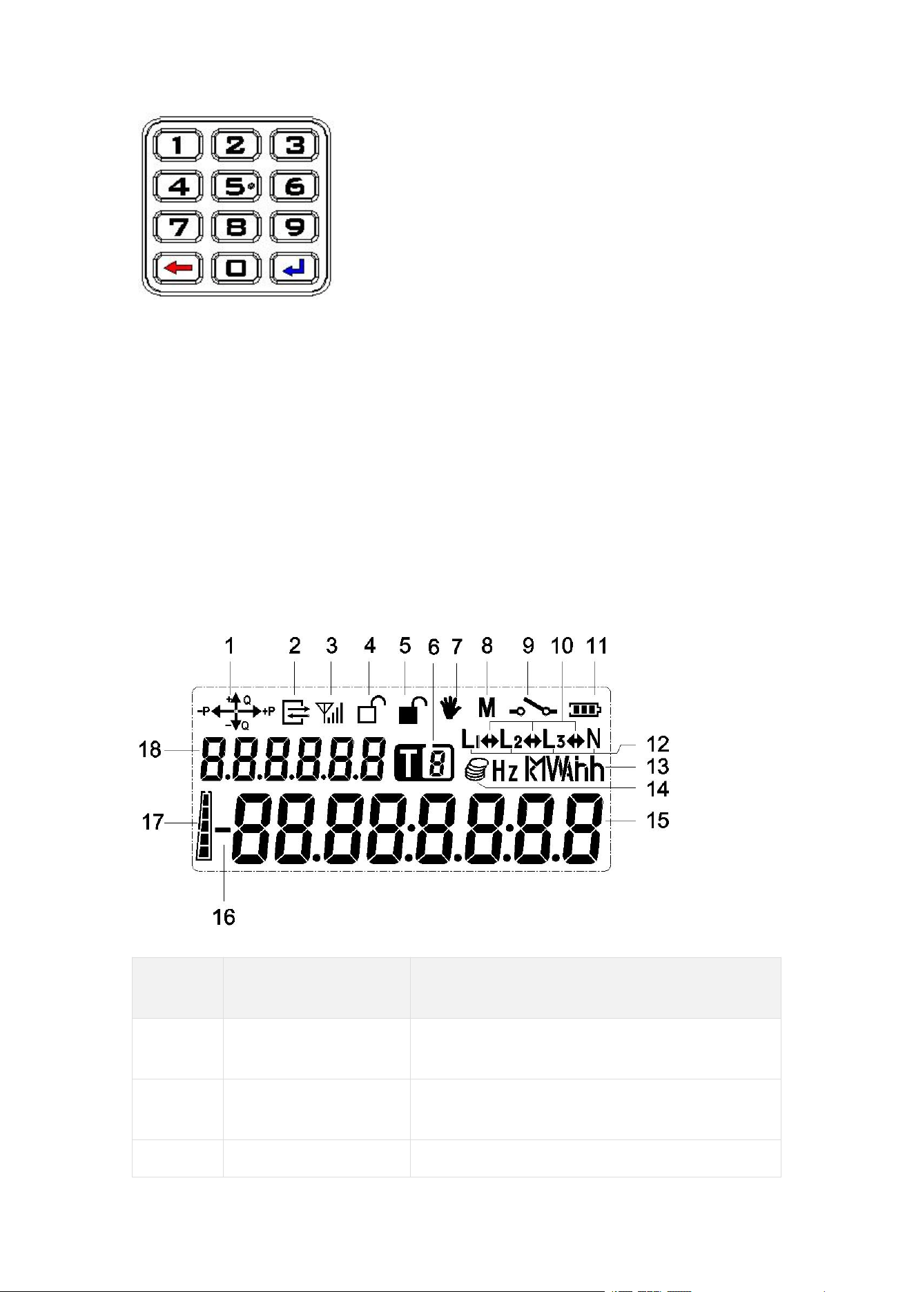
5.2 Keypad (Optional)
The meter keypad clearly displays each key, including numeric keys
from 0 to 9, a backspace key, and an enter key.
If input is incorrect, use the "Backspace" key on the keypad to delete.
After input is complete, press the "Enter" key to execute the numeric
command.
The meter supports paging through displays by pressing the enter
key.
5.3 Backlight Indicator
The meter supports a backlight function. When the meter is powered
on, any key input will activate the backlight to facilitate viewing the
meter display information. After the backlight is triggered by a key, it
will automatically turn off after a period of inactivity.
5.4 Display
5.4.1 LCD Display Content Description
Display
No.
Symbol Name
Description
1
Quadrant Indicator
Indicates the current combined phase
active and reactive power direction.
2
Communication
Indicator
Symbol displays when meter
communication occurs.
3
Module
GPRS communication connection

Communication
Status Indicator
status and signal strength indicator.
4
Upper Cover Open
Indicator
This symbol displays when the upper
cover is open; disappears when the
upper cover is closed.
5
Terminal Cover
Open Indicator
This symbol displays when the terminal
cover is open; disappears when the
terminal cover is closed.
6
Tariff Flag
Indicates the current tariff number.
7
Tamper Indicator
Realtime indication of the meter's
tamper state:
This symbol displays when tampering
occurs;
Disappears when no tampering event
is active and after tamper clear.
8
Reserved
Reserved.
9
Relay Status
Indicator
This symbol displays when the relay is
open;
Disappears when the relay is closed.
10
Power Flow
Direction Indicator
Points right during forward power flow;
Points left during reverse power flow;
Symbol disappears when no power is
consumed.
11
Battery Indicator
Realtime indication of battery status.
Displays when battery voltage is below
3.0V; disappears when battery voltage
recovers above 3.0V.
12
Phase Voltage
Presence Indicator
Symbol displays when phase line is
present; disappears when phase is
lost.
Letter "N":
Displays when meter neutral line is
present;
Disappears when meter neutral line is
disconnected.
13
Unit Display Area
Unit symbols for energy, power
(demand), voltage, current, etc.
14
Reserved
Reserved
15
Data Display Area
Displays various data content indicated
by the display code. For data items
exceeding 8 digits (e.g., date/time,
meter number), the meter
automatically displays them across
multiple screens.
16
Reserved
Reserved
17
Balance Indicator
Bar
Realtime indication of balance.
18
Data Identifier
Display Area
Used to identify different display items
(displayed as OBIS code
abbreviations).
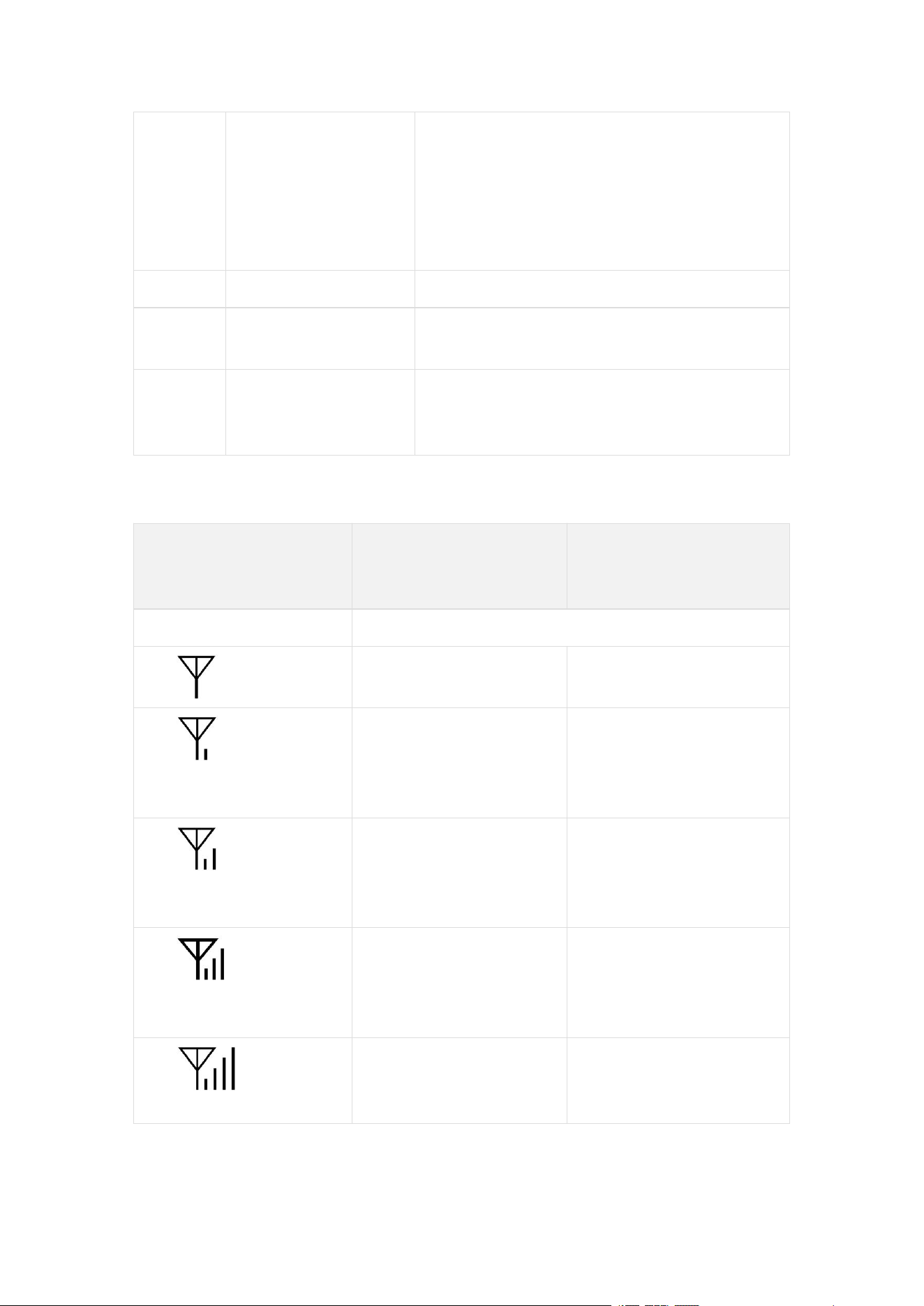
5.4.1.1 GPRS/3G/4G Module Signal Indicator Description
GPRS/3G/4G Signal
Indicator Symbol
State
Meaning (Steady
On)
Meaning (Flashing)
No display
Communication module not detected.
No signal (below
-111dBm)
SIM card error
Signal: -111 to
-108dBm, Connected
to base station
Signal: -111 to
-108dBm, Not
connected to base
station
Signal: -107 to
-102dBm, Connected
to base station
Signal: -107 to
-102dBm, Not
connected to base
station
Signal: -101 to
-92dBm, Connected
to base station
Signal: -101 to
-92dBm, Not
connected to base
station
Signal: -91dBm or
higher, Connected to
base station
Signal: -91dBm or
higher, Not connected
to base station
5.4.2 Auto-scroll Display

When the meter is powered on and inactive, the LCD enters
auto-scroll display mode.
The meter's auto-scroll display list and display interval time are
configurable. Default parameters are in the technical parameter table.
5.4.3 Button-triggered Display
When the meter is in auto-scroll display mode, briefly press the
display button to enter button-triggered display mode.
The meter's button-triggered display list and the time to return to
auto-scroll are configurable. Default parameters are in the technical
parameter table.
5.4.4 Popup Display
When certain events occur, the meter displays a popup prompt for the
event. See the table below.
Display
Content
Meaning
Remarks
OPEN TER
Terminal cover open
Specific display effect is
subject to the actual product.
OPEN COV
Meter cover open
MAGNET
Magnetic field
interference
OVERHEAT
Over temperature
LOST U 1
Phase A has current
but no voltage
LOST U 2
Phase B has current
but no voltage
LOST U 3
Phase C has current
but no voltage
BYPASS
Bypass
5.4.5 Power Loss Display
5.4.5.1 Constant Display during Power Loss

The electricity meter supports a constant display function during
power loss.
The constant display hold time during power loss is configurable,
range 0 seconds to 7 days.
5.4.5.2 Power Loss Wake-up Display
The electricity meter supports a wake-up display function via button
press during power loss.
Pressing the display button can wake up the LCD display; pressing
the display button again can switch to the next item in the auto-scroll
list.
The display turns off after a period of inactivity.
5.5 LED Indicators
5.5.1 Pulse Indicator
Active LED: Red LED, flashes at a frequency defined by the
pulse constant when active energy is consumed.
Reactive LED: Red LED, flashes at a frequency defined by the
pulse constant when reactive energy is consumed.
5.5.2 Alarm Indicator
The alarm LED stays steadily on after the relay trips.
When the relay is closed and an alarm event occurs, the alarm
LED flashes.
When the relay is closed and all alarm events have ended, the
alarm LED turns off.
Alarm events are as follows:
No.
Event
1
Upper cover open
2
Terminal cover open
3
Magnetic field interference
4
Bypass

5.5.3 Credit/Power Indicator
5.5.3.1 Prepayment Mode
When the meter is powered on:
When remaining credit is exhausted, the red LED stays steadily
on.
When remaining credit is greater than 0 and less than or equal
to alarm threshold 2, the red LED flashes.
When remaining credit is greater than alarm threshold 2 and
less than or equal to alarm threshold 1, the green LED flashes.
When remaining credit is greater than alarm threshold 1, the
green LED stays steadily on.
5.5.3.2 Postpayment Mode
When the meter is powered on, the green LED stays steadily on.
6 Load Management
The electricity meter can be programmed to set user load limits. Load
limits include active power limit and current limit. An overload
condition is triggered when either limit is exceeded.
6.1 Load Control
The electricity meter supports load control function. Overload (or
overcurrent) handling is as follows:
If overload (or overcurrent) duration reaches 60 seconds, the
relay opens, and automatically closes after 30 seconds.
If the relay opens due to overload (or overcurrent) for 6
consecutive times, after opening, it can only automatically close
after 30 minutes.
The lockout time after exceeding the overload (or overcurrent)
count is configurable, default is 30min.
7 Relay Control
The electricity meter's relay control function model complies with the
DLMS specification. The relay's logical state, physical state, and

control mode can be read via local communication and remote
communication.
7.1 Common Trip Reasons
No.
Trip Reason
1
Insufficient credit
2
Overcurrent/Overload
3
Overvoltage/Undervoltage
4
Meter detects tampering
8 Event Logging
The electricity meter logs the most recent group of events, including
their date/time of occurrence, in a first-in-first-out manner. Event logs
can be uploaded to the host management computer via the
communication interface for display, reporting, and appropriate action
by the power supply management department.
8.1 Event Detection
Event Code
Event Name
Chinese Description
7
Replace Battery
Battery needs replacement
76
Under voltage L1
L1 phase undervoltage
77
Under voltage L2
L2 phase undervoltage
78
Under voltage L3
L3 phase undervoltage
79
Over voltage L1
L1 phase overvoltage
80
Overvoltage L2
L2 phase overvoltage
81
Overvoltage L3
L3 phase overvoltage
82
Missing voltage L1
L1 phase voltage loss
83
Missing voltage L2
L2 phase voltage loss
84
Missing voltage L3
L3 phase voltage loss
88
Phase sequence reversal
Reverse phase sequence

91
Current Reversal
Current reversal
/
Power failure
Long power failure
9 Time-of-Use Tariff
The meter supports TOU (Time-of-Use) tariff functionality.
10 Tiered Energy (Only for
Prepayment Meters)
The meter supports tiered energy functionality.
11 Tariff (Only for Prepayment
Meters)
11.1 Time-of-Use Tariff
The meter supports Time-of-Use tariff functionality. Each TOU tariff
number corresponds to a time-of-use tariff.
The meter supports backup time-of-use tariff functionality. The
activation time for backup time-of-use tariff parameters is
configurable.
11.2 Tiered Tariff
The meter supports tiered tariff functionality. Each tier type
corresponds to a tiered tariff.
The meter supports backup tiered tariff functionality. The activation
time for backup tiered tariff parameters is configurable.
12 Payment Mode (Only for
Prepayment Meters)

12.1 Prepayment Mode
Energy accumulation and credit deduction proceed normally. The
credit indicator light indicates the current balance status according to
the set credit alarm thresholds. When the balance decreases to 0, the
electricity meter opens the relay (in non-friendly power-off mode), and
the user must recharge to resume electricity use.
In prepayment mode, the meter supports standard STS test TOKENs
for querying related prepayment information.
12.2 Postpayment Mode
The user's electricity consumption only accumulates energy, without
deduction or any relay operation. In postpayment mode, the credit
indicator light stays steadily green. If the relay is open due to
insufficient balance or debt in prepayment mode, switching to
postpayment mode will automatically close the relay, allowing normal
power supply and energy metering.
In postpayment mode, purchase tokens and clear balance tokens are
not accepted.
12.3 Payment Mode Switching
The meter can switch payment modes via a special TOKEN.
When the meter switches payment mode, corresponding event
records are logged. See the Event Logging chapter for details.
13 Prepayment (Only for
Prepayment Meters)
The vending system generates a 20-digit numeric sequence (TOKEN)
based on user information and purchase amount. The user inputs this
20-digit sequence via the keypad on the meter. The meter performs
decryption, writes the purchase amount into the meter after key
authentication, adds the purchase amount to the remaining credit,
and stores it. In case of emergency use, the emergency credit amount
is deducted first from the purchase amount, then the remainder is

added to the remaining credit and stored. When the user consumes
electricity, the meter deducts from the remaining credit according to
corresponding conditions. When power-off conditions are met, the
meter automatically cuts off the user load. When power-on conditions
are met, the meter automatically restores the user load.
The meter uses combined active energy (forward + reverse) for
deduction and settlement.
The meter supports TOKEN credit, emergency credit, and friendly
credit, and supports TOU tariffs and tiered tariffs.
13.1 TOKEN Credit
13.1.1 Purchasing Electricity
When the remaining credit in the meter is insufficient, the user can go
to the vending office to purchase electricity. The office generates a
20-digit numeric sequence, i.e., a token (TOKEN), based on user
information and purchase amount.
Purchasing method:
1. Go to the local vending office.
2. Provide the meter ID number to the operator.
3. Tell the operator the amount you wish to purchase and pay.
4. On the receipt, you receive a printed token [20-digit number].
13.1.2 Loading Electricity
The user inputs the 20-digit numeric sequence on the meter. After
passing key authentication, the meter accepts the purchase amount,
adjusts the remaining credit and cumulative purchase amount
accordingly, and displays the loaded amount.
Remote prepayment keypad meters support online recharge.
Recharge TOKENs can be issued directly by the vending staff for
meter recharge, or users can input recharge TOKEN codes.
Manually inputting purchase token into the meter:
1.
Input the 20-digit token via the meter keypad.

2.
For keypad code meters, if the token input is incorrect, use the
"Backspace" key to delete. After all 20 digits are entered, press
the "Enter" key to process the token acceptance.
3.
If the token input is correct, the LCD will sequentially display
"accept", the amount purchased this time, and the remaining
credit.
4.
If the token input is incorrect, the LCD will display "reject".
13.2 Emergency Credit
When the current time is not within the friendly credit period and the
user's balance is below a specific threshold, the user can activate the
emergency credit function via the keypad (any number key + enter
key), until the emergency credit amount is used up. The emergency
credit function can only be used once, and is restored after the next
recharge. The emergency credit amount is automatically deducted
during the next recharge.
The meter can query the set emergency credit amount threshold via a
short code.
Emergency credit related parameters can be programmed via the
host management software.
13.3 Friendly Credit
13.3.1 Friendly Day
The meter's friendly day can be set via software.
Electricity use is unrestricted throughout the friendly day.
13.3.2 Friendly Period
The meter's friendly period can be set via software.
Credit deduction is unrestricted during the friendly period.
13.4 Low Credit Alarm Function
The meter can be programmed to set two-level low credit alarm
threshold values, both default to 0.
The indicator light status prompts for different credit states of
the meter refer to the Human Machine Interface chapter.