100271422_2000527669_Rev H
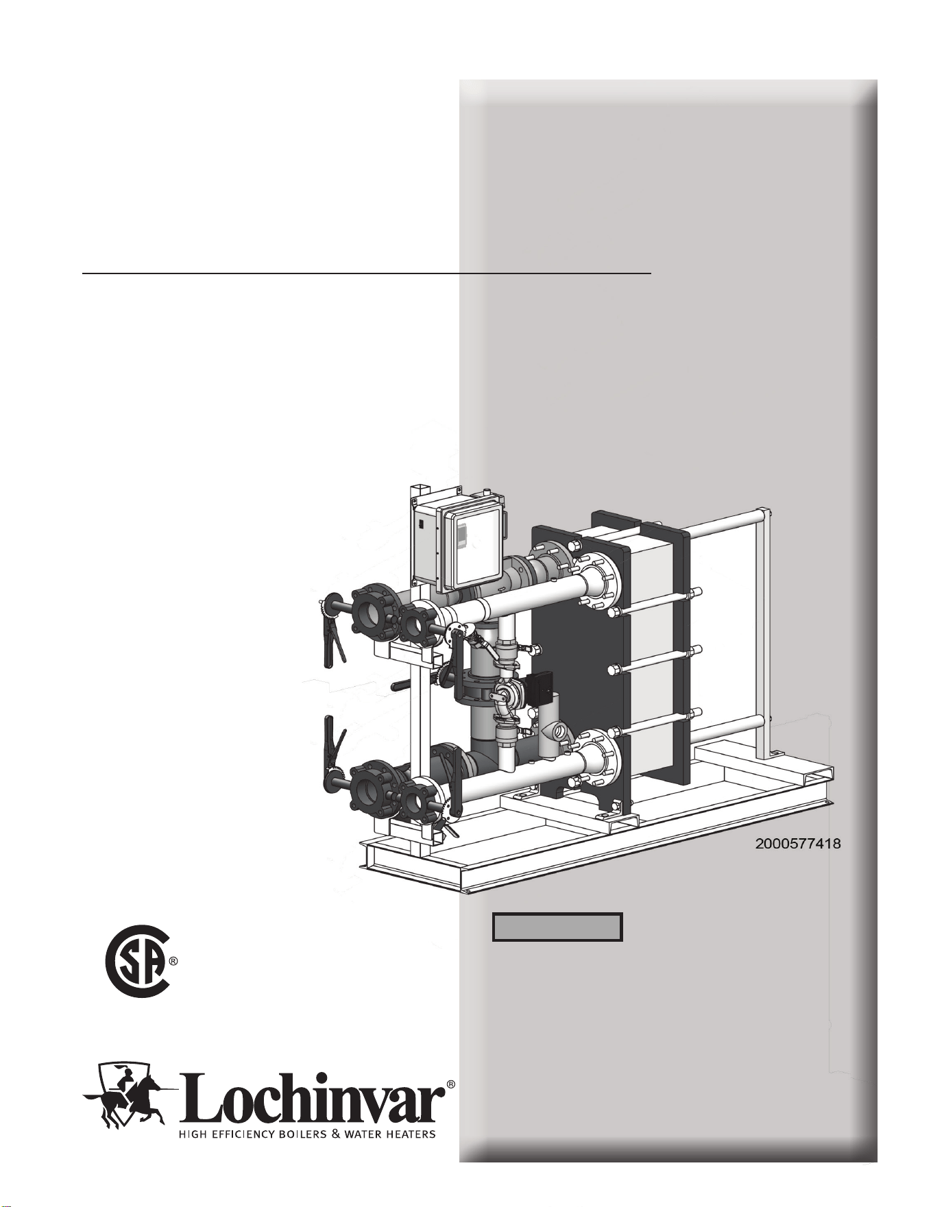
Indirect Plate Water Heater
Installation & Service Manual
Double-Wall Models:
IPW015DW - IPW120DW
Series 100
This manual must only be used by
a qualified heating installer / service
technician. Read all instructions
before installing. Perform steps in
the order given. Failure to comply
could result in severe personal
injury, death, or substantial property
damage.
⚠WARNING
Save this manual for future reference.
LOW LEAD CONTENT

2
Hazard definitions
The following defined terms are used throughout this manual to bring attention to the presence of hazards of various risk levels or
to important information concerning the life of the product.
⚠ DANGER
⚠WARNING
⚠CAUTION
CAUTION
NOTICE
DANGER indicates an imminently hazardous situation which, if not avoided, will result in death or serious
injury.
WARNING indicates a potentially hazardous situation which, if not avoided, could result in death or serious
injury.
CAUTION indicates a potentially hazardous situation which, if not avoided, may result in minor or moderate
injury.
CAUTION used without the safety alert symbol indicates a potentially hazardous situation which, if not
avoided, may result in property damage.
NOTICE indicates special instructions on installation, operation, or maintenance that are important but not
related to personal injury or property damage.
HAZARD DEFINITIONS .................................................. 2
PLEASE READ BEFORE PROCEEDING ..................... 3
THE IPW -- HOW IT WORKS .......................................... 4
1. DETERMINE IPW LOCATION
Before locating the appliance, check: ................................ 5
Site selection and preparation ........................................... 5
Installation clearances ....................................................... 5
• IPW Water Heater Clearances ................................... 6
2. PREPARE WATER HEATER
Receiving and unpacking the IPW ..................................... 7
Setting the unit ................................................................... 7
3. HYDRONIC PIPING
IPW piping assemblies ....................................................... 8
General piping information ................................................. 8
Heating fluid and Domestic Hot Water (DHW) piping ........ 8
Scalding ............................................................................... 8
Hydronic piping illustrations ......................................... 9-14
4. ADJUSTMENTS
3-Way control valve adjustment ....................................... 15
• Control valve calibration and status indications .. 15-16
• Manual control of 3-way valve............................. 16-17
Temperature Controller Operating Controls ..................... 18
5. OPERATING INFORMATION
Sequence of operation ..................................................... 19
Electronic control overview .............................................. 19
Over-temperature control and safety features ................. 19
6. WIRING
Electrical wiring connections ............................................ 20
7. MODBUS
Installation procedure ....................................................... 21
ModBus eException Codes .............................................. 22
Primary Data Tables ........................................................ 23
Memory Map .................................................................... 23
Physical Wiring ................................................................. 23
Procedure to change ModBus address ............................ 24
Troubleshooting ................................................................ 24
8. START-UP
Introduction ....................................................................... 25
Pre-operational checks and procedures .......................... 25
Initial start-up .................................................................... 25
Checking mixed inlet temperature ................................... 26
Shutting down the system ................................................ 26
9. MAINTENANCE
Maintenance and annual startup ...................................... 27
Periodic cleaning of heat exchanger ................................ 28
Strainers - inspection and replacement ........................... 28
Oiled bearing circulators .................................................. 28
Check water heater relief valve ........................................ 28
10. TROUBLESHOOTING
• Table 10A - Troubleshooting Chart - No Display ..... 29
Checking temperature sensors ........................................ 30
• Table 10B - Resistance vs. Temperature ................ 30
11. SIZING DATA
How to properly size your Indirect Water Heater ......... 31-38
12. DIAGRAMS
Wiring Diagram ............................................................... 39
13. REPLACEMENT PARTS LIST
When ordering replacement parts ..................................... 40
Revision Notes .................................................. Back Cover
Contents

3
Indirect Plate Water Heater Installation & Service Manual
Please read before proceeding
Installer – Read all instructions, including
this manual before installing. Perform
steps in the order given.
User – This manual is for use only
by a qualified heating installer/
service technician. Refer to the User’s
Information Manual for your reference.
Have this Indirect Plate Water Heater
(IPW) serviced/inspected by a qualified
service technician, at least annually.
Failure to comply with the above could
result in severe personal injury, death or
substantial property damage.
Failure to adhere to the guidelines on this
page can result in severe personal injury,
death, or substantial property damage.
When calling or writing about the IPW
– Please have the IPW model and serial
number from the rating label.
Consider piping and installation when
determining IPW location.
Any claims for damage or shortage in
shipment must be filed immediately
against the transportation company by
the consignee.
Factory warranty (shipped with unit) does
not apply to units improperly installed or
improperly operated.
⚠WARNING
NOTICE
⚠WARNING
General information –
This instruction manual provides detailed coverage for the
Indirect Plate Water Heater (IPW). Each IPW is equipped
with an electronic control system specifically designed for
an electronic control valve. This control system and valve
combination can be used with all models and sizes of IPW
water heaters. The IPW is available in the following double-
wall heat exchanger models:
• Double-Wall Models
IPW015DW, 030DW, 050DW, 070DW, 090DW,
105DW, and 120DW
A typical packaged IPW water heater with a double-wall heat
exchanger is depicted on page 4.
Identical electronic control systems are used on all IPW
models. This system contains a control box assembly which
includes all of the electronic circuitry for the electronic
control system. In addition, the electronic control system
includes several sensors and safety devices which provide
temperature and flow control information to the control box
circuitry. The additional devices included in the electronic
control are as follows:
• DHW Inlet Temperature Sensor (RTD)
• DHW Outlet Temperature Sensor (RTD)
• Over-Temperature Switch (With Safety Shutdown)
If desired, the ModBus communication option permits the
electronic control system to be externally controlled by an
Energy Management System (EMS), Building Automation
System (BAS), or computer supplied by other manufacturers.
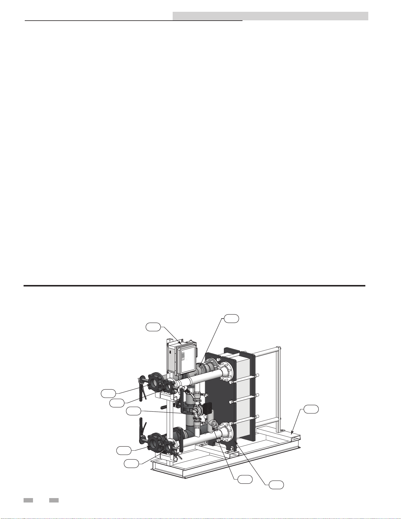
The IPW - How it works...
1. Control valve
The 3-way electronic control valve is powered by 24 VAC
which is received from the electronic control system control
box. The temperature controller in the control box supplies
a 0 - 10 VDC control signal to precisely modulate the 3-way
valve to accurately control the temperature of the DHW
output to the desired set point.
2. System water outlet
ANSI flanged connections (2", 3", or 4" depending on model
size) with carbon steel piping that returns boiler water back to
the system loop.
3. System water inlet
ANSI flanged connections (2", 3", or 4" depending on model
size) with carbon steel piping that receives boiler water from
the system loop.
4. P & T Relief valve
Protects the heat exchanger from an over pressure condition.
The relief valve provided with the unit is set at 150 psi and
210°F.
5. Electronic control system control box
Contains a control box assembly which includes all of the
electronic circuitry for the electronic control system. In
addition, the electronic control system includes several sensors
and safety devices which provide temperature and flow control
information to the control box circuitry.
6. DHW inlet
ANSI flanged connections (2" or 3" depending on model size) with
stainless steel piping that receives cold water from the DHW
piping.
7. DHW outlet
ANSI flanged connections (2" or 3" depending on model size) with
stainless steel piping that delivers heated water back to the DHW
piping.
8. Recirculation pump
The recirculation pump helps prevent scale buildup by providing
constant recirculation through the heat exchanger on the DHW
side. It also preheats the cold water before it enters the heat
exchanger.
9. Heat exchanger
Allows water to flow between plates for maximum heat transfer
while keeping boiler water from contacting potable water.
10. Frame / skid assembly
Supports the HEX and piping while providing another method to
move and transport the unit.
4
DIR #2000577418
5
2
6
8
4
9
3
7
10
1
Typical IPW Packaged Water Heater
Indirect Plate Water Heater Installation & Service Manual

5
Before locating the appliance, check:
1. Check for nearby connection to:
• Heating system water piping
• Electrical power
• DHW system water piping
2. Locate the appliance so that if water connections
should leak, water damage will not occur. When such
locations cannot be avoided, it is recommended that a
suitable drain pan, adequately drained, be installed
under the appliance. Under no circumstances is the
manufacturer to be held responsible for water damage
in connection with this appliance, or any of its
components.
3. If a new water heater will replace an existing water
heater, check for and correct system problems, such as:
• System leaks causing oxygen corrosion or heat
exchanger cracks from hard water deposits.
• Incorrectly-sized expansion tank.
• Lack of freeze protection in the appliance water
causing the system and the appliance to freeze and
leak.
⚠WARNING
This appliance is certified as an indoor
appliance. Do not install the appliance
outdoors or locate where the appliance will
be exposed to freezing temperatures or to
temperatures that exceed 100°F.
Do not install the appliance where the
relative humidity may exceed 95%. Do not
install the appliance where condensation
may form on the inside or outside of the
appliance, or where condensation may fall
onto the appliance.
Installation clearances
1 Determine IPW location
The heater must be installed with the prescribed clearances
for service as shown in FIG. 1-1 on page 6. The recommended
minimum clearance dimensions are listed below; however, if
local building codes require additional clearances, these codes
shall supersede the recommendations listed below:
• Sides: 24 in. (61 cm)
• Front: 24 in. (61 cm)
• Rear: 24 in. (61 cm)
• Top: 12 in. (30.5 cm)
All water piping and electrical conduit must be arranged so
that it does not interfere with the removal of the IPW water
heater assemblies/parts or inhibit service or maintenance of
the unit.
Site selection and preparation
Ensure that the site selected for installation of the IPW water
heater includes the following:
• Access to AC input power at 120 VAC/60 Hz
• Close proximity to system boiler loop to be used as heating
fluid source.
• If applicable, access to ModBus network wiring within the
prescribed wire lengths (see the Section 6 - Wiring)
Indirect Plate Water Heater Installation & Service Manual
1 Determine water heater location
(A)
(D)
(B)
(E)
(C)
24.00
24.00
24.00
24.00
DIR #200057741
9
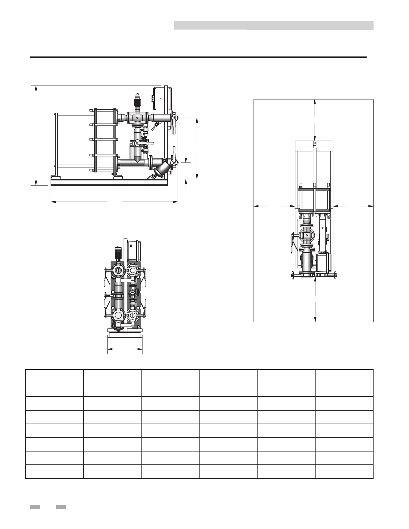
Figure 1-1 IPW Water Heater Clearances and Dimensions
6
Indirect Plate Water Heater Installation & Service Manual
MODEL A B C D E
IPW015DW 56" 37 3/4" 15" 30 3/4" 5 1/2"
IPW030DW 56" 43 1/2" 15" 30 3/4" 5 1/2"
IPW050DW 56" 43 1/2" 15" 30 3/4" 5 1/2"
IPW070DW 63" 50 1/4" 22" 36 3/4" 8 1/2"
IPW090DW 63" 56 1/2" 22" 36 3/4" 8 1/2"
IPW105DW 63" 54 1/2" 22" 36 3/4" 8 1/2"
IPW120DW 63" 52 1/2" 22" 36 3/4" 8 1/2"
7
Receiving and unpacking the IPW
All of the IPW water heaters are shipped fully assembled and
ready for installation; therefore, installation will consist of the
following tasks:
• Unpack the IPW water heater from its shipping container
• Position and secure the IPW water heater at the site
• Connect the heating loop/system piping to the IPW
• Connect the Domestic Hot Water (DHW) piping to the
IPW
• Connect external AC power to the IPW electronic
control box
• If required, connect ModBus control wiring to the
temperature controller in the electronic control box
Each IPW water heater is shipped as a single crated unit. The
unit must be moved with the proper equipment (forklift,
pallet jack, etc.) to avoid possible injury to personnel or
damage to the shipping container or unit. The shipping
carton should be inspected for damage incurred during
transit prior to signing the bill of lading.
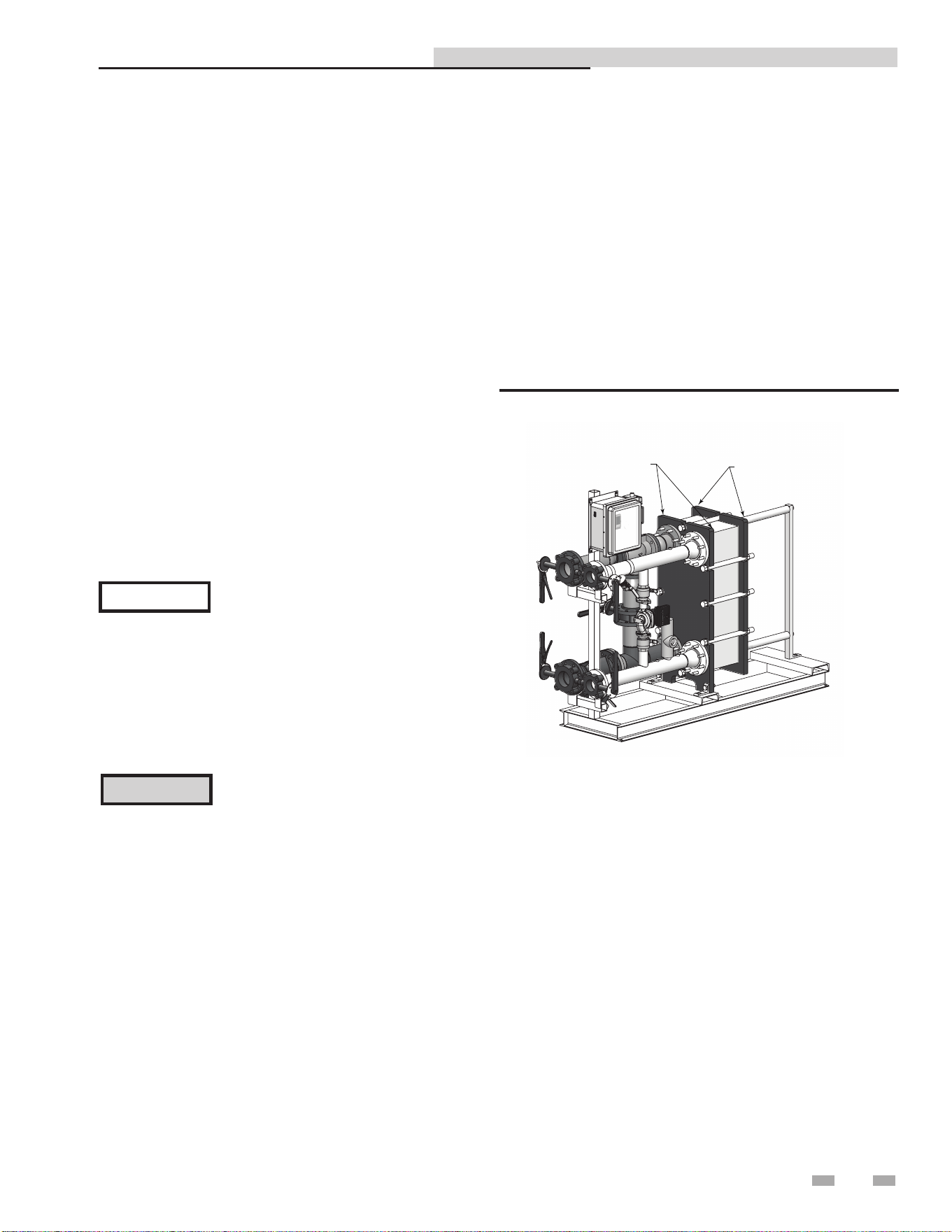
Setting the unit
IPW water heaters contain two (2) round cutouts on the frame
plate and two (2) on the pressure plate of the heat exchanger
(FIG. 2-1). Use these tabs or cutouts to lift and move the unit
as specified in the heat exchanger (HEX) manual supplied with
the unit.
In multiple unit installations, it is important to plan the
position of each unit in advance. Sufficient space for piping
connections and future service/maintenance requirements must
also be taken into consideration. All piping must include ample
provisions for expansion.
FRAME PLATE CUTOUTS
PRESSURE PLATE CUTOUTS
DIR #2000577418
Figure 2-1 Lifting Provisions
2 Prepare water heater
Lochinvar is not responsible for lost or
damaged freight. The freight carrier must
be notified immediately of any damage
detected.
NOTICE
Unpack the IPW water heater from its shipping container
taking care not to damage the unit when cutting away the
packaging material. Remove the bolts securing the IPW to
its shipping skid. Perform a complete visual inspection of the
unit to ensure there is no evidence of damage.
CAUTION
While packaged in the shipping container,
the heater must be moved using a forklift
or pallet jack. After unpacking, the
heater should be lifted and moved using
the frame cutouts (double-wall model)
provided on the heater.
Indirect Plate Water Heater Installation & Service Manual
8
3 Hydronic piping
IPW piping assemblies
The diameter of the piping assemblies furnished with the
water heater will depend on the size of the heat exchanger
installed in the model ordered. Smaller sized models utilize 2"
piping assemblies, while all other sizes utilize 3" and 4" piping
assemblies used in each double-wall model. See Table 3A for
sizing of piping assemblies used in each double-wall model.
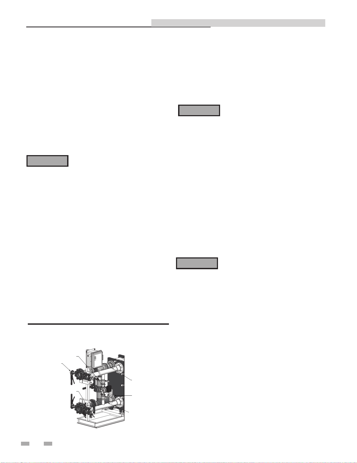
General piping information
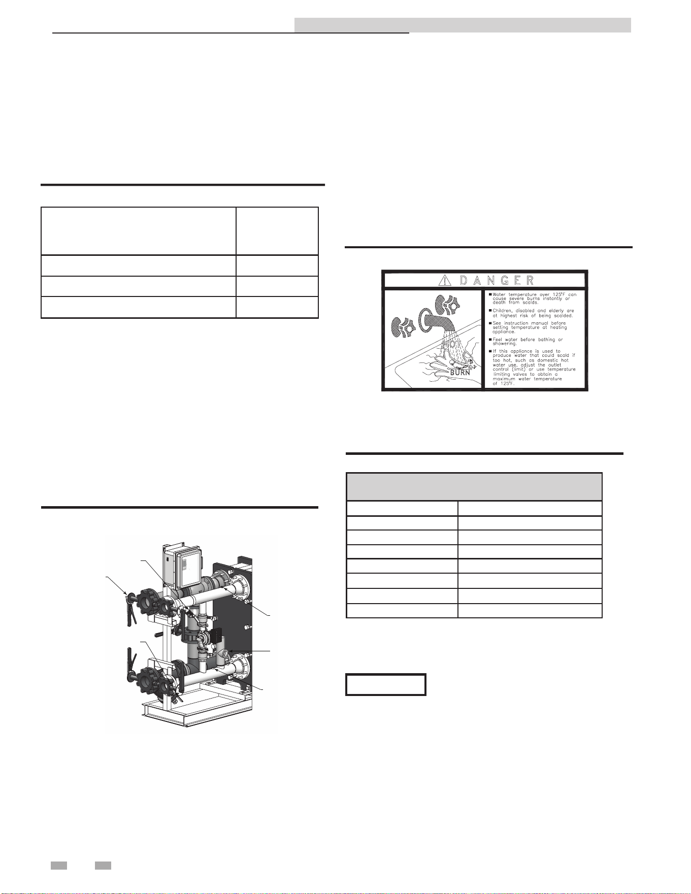
In addition to the heat exchanger and piping components, each
IPW piping assembly contains a number of other important
components and assemblies:
• Recirculation Pump (Continuously ON)
• Isolation
• Strainers (Boiler Water & DHW Sides)
• Blow-down Valves
• Pressure & Temperature (P & T) Relief Valve
Figure 3-1 illustrates the locations of the above mentioned
components for a double-wall heat exchanger.
ISOLA
TION VALVES
(4 PLACES)
OUTLET RTD
INLET RTD
P & T RELIEF VALV
E
BOILER WATER STRAINER
W/BLOW-DOWN VALVE
DOMESTIC WATER STRAINER
W/BLOW-DOWN VALVE
DIR #2000577647
Figure 3-1A Typical IPW Piping
Heating fluid and Domestic Hot Water
(DHW) piping
The diameter of the heating fluid (hot boiler water) and DHW
piping will depend on the model number and size of the water
heater being installed. Reference Table 3A (this page) for
applicable piping sizes.
Table 3A IPW Piping Assemblies
Model
Piping
Assembly
Diameter
IPW015 - IPW050 2"
IPW070 - IPW090 3"
IPW105 - IPW120 4"
Indirect Plate Water Heater Installation & Service Manual
Scalding
This water heater can deliver scalding temperature water at any
faucet in the system. Be careful whenever using hot water to avoid
scalding injury. Certain appliances such as dishwashers and
automatic clothes washers may require increased temperature
water. By setting the thermostat on this water heater to obtain
the increased temperature water required by these appliances,
you may create the potential for scald injury. To protect against
injury, you should install a mixing valve in the water system.
This valve will reduce point of discharge temperature by mixing
cold and hot water in branch supply lines. Such valves are
available from the local plumbing supplier.
Figure 3-1B Scald Warning
The following chart (Table 3B) details the relationship of water
temperature and time with regard to scald injury and may be
used as a guide in determining the safest water temperature for
your applications.
APPROXIMATE TIME / TEMPERATURE
RELATIONSHIPS IN SCALDS
120°F More than 5 minutes
125°F 1 1/2 to 2 minutes
130°F About 30 seconds
135°F About 10 seconds
140°F Less than 5 seconds
145°F Less than 3 seconds
150°F About 1 1/2 seconds
155°F About 1 second
Table 3B Approximate Time / Temperature Scald Chart
Anti-scald mixing valve:
Field supplied. An anti-scald mixing valve is recommended
when domestic hot water supply is above 115°F.
The water inlet and outlet threaded
connections are steel. When connecting
the unit to piping made of a different
material, use of a dielectric fitting or a
dielectric union conforming to ASSE 1079
is recommended to prevent corrosion and
potential subsequent water leaks at or near
the connection. Dielectric fittings may be
required by local plumbing codes.
NOTICE
9
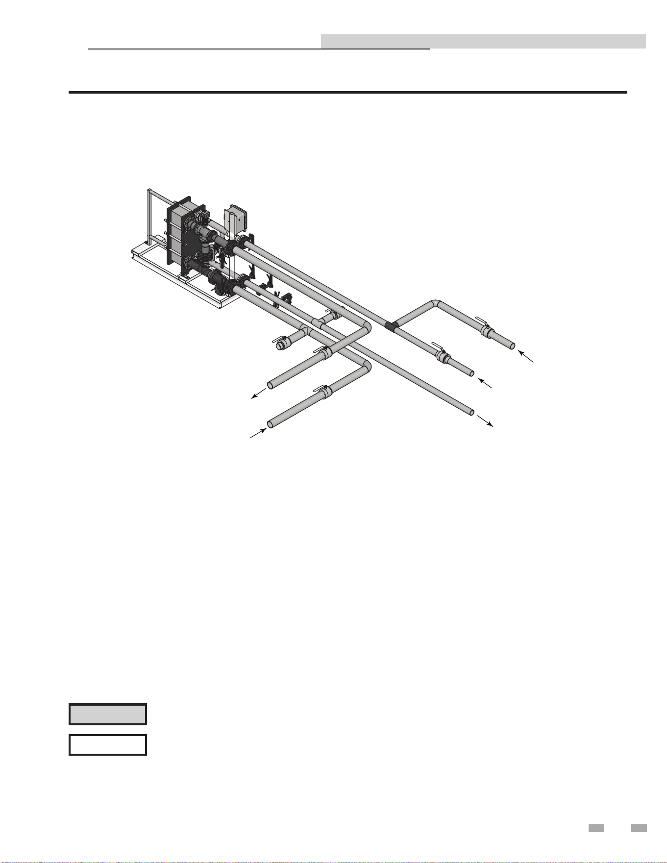
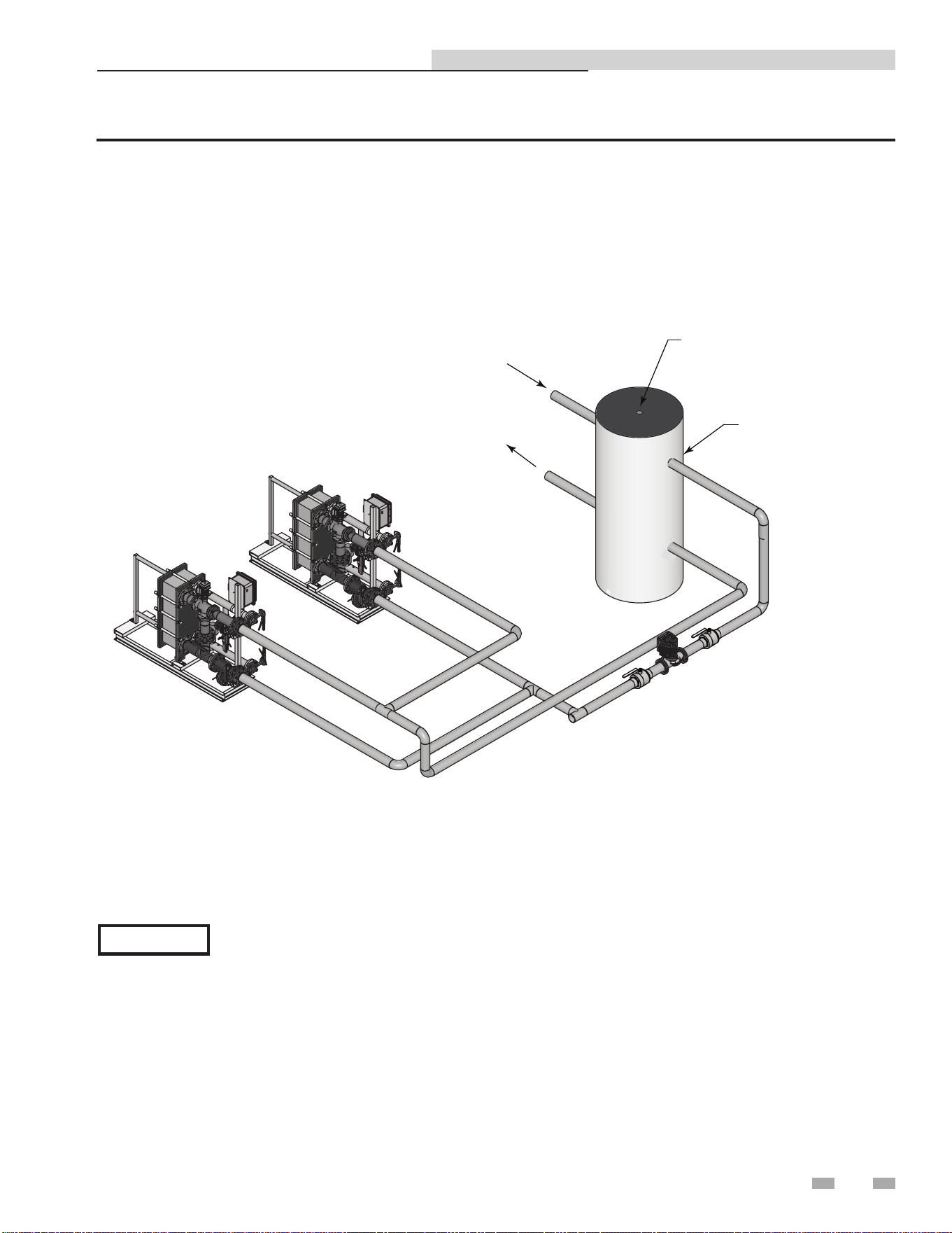
3 Hydronic piping (continued)
DIR #2000577498
BUILDING
RETURN
COLD WATER SUPPLY
HOT WATER SUPPLY
BOILER WATER IN
BOILER WATER OUT
Figure 3-2 Water to Water Heat Exchanger Single Unit
Please note that these illustrations are meant to show system piping concept only, the installer is responsible
for all equipment and detailing required by local codes.
NOTICE
Indirect Plate Water Heater Installation & Service Manual
CAUTION
Mixing valves are required for the protection of low temperature loops.
10
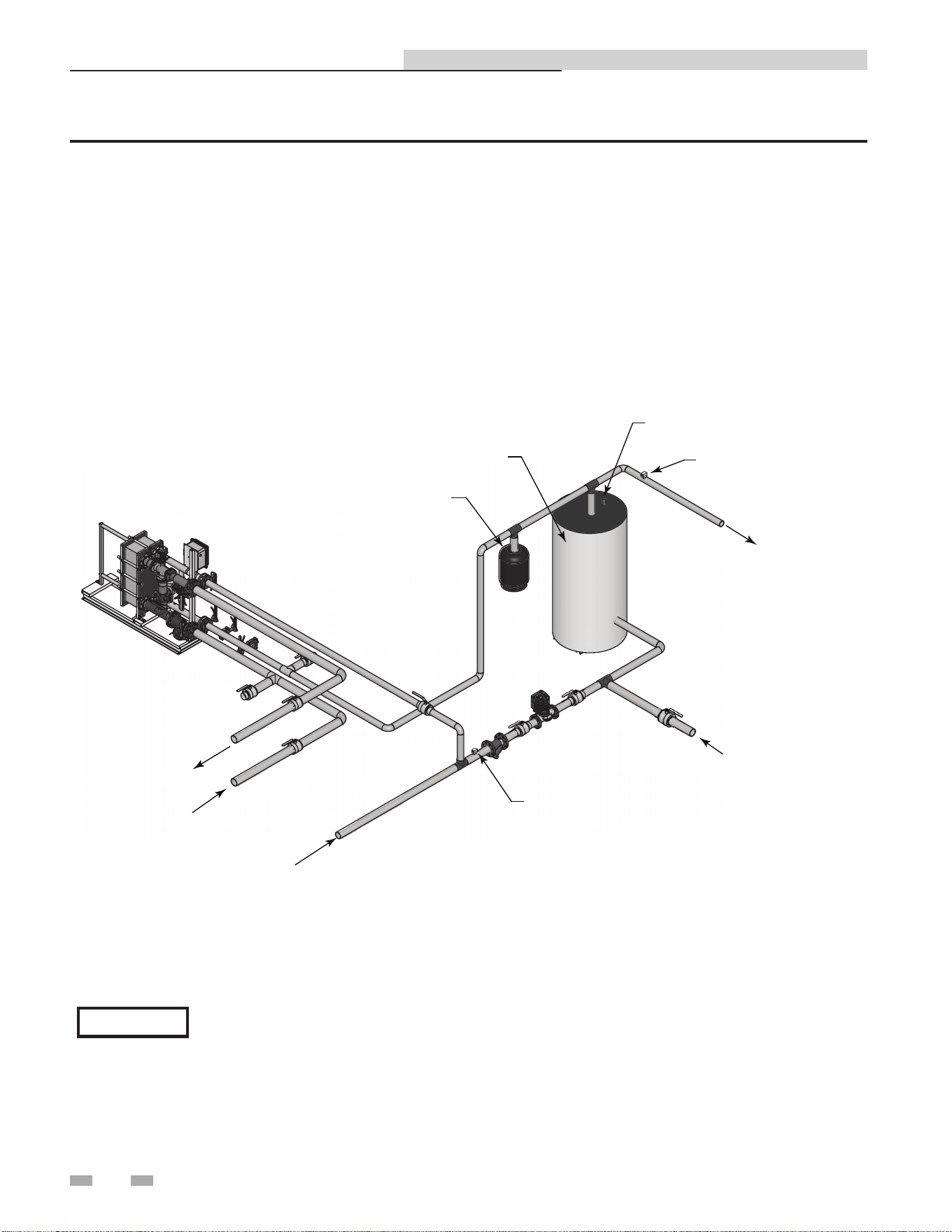
3 Hydronic piping
DIR #2000577516
D
IR
#
2000577516
COLD WATER SUPPLY
FLOW INDICATOR
PUMP
BUILDING RETURN
BOILER WATER
IN
BOILER
WATER
OUT
EXPANSION TANK
RELIEF VALVE
STRATIFIED HOT WATER
STORAGE TANK
TANK HEIGHT TO DIAMETER
RATIO 2:1 MIN., 3:1 PREFERRED
HOT WATER SUPPLY
TEMPERA
TURE GAUGE
Figure 3-3 Water to Water Heat Exchanger Single Unit with Stratified Tank
Please note that these illustrations are meant to show system piping concept only, the installer is responsible
for all equipment and detailing required by local codes.
NOTICE
Indirect Plate Water Heater Installation & Service Manual
11
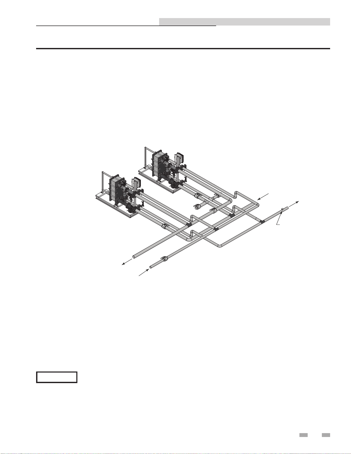
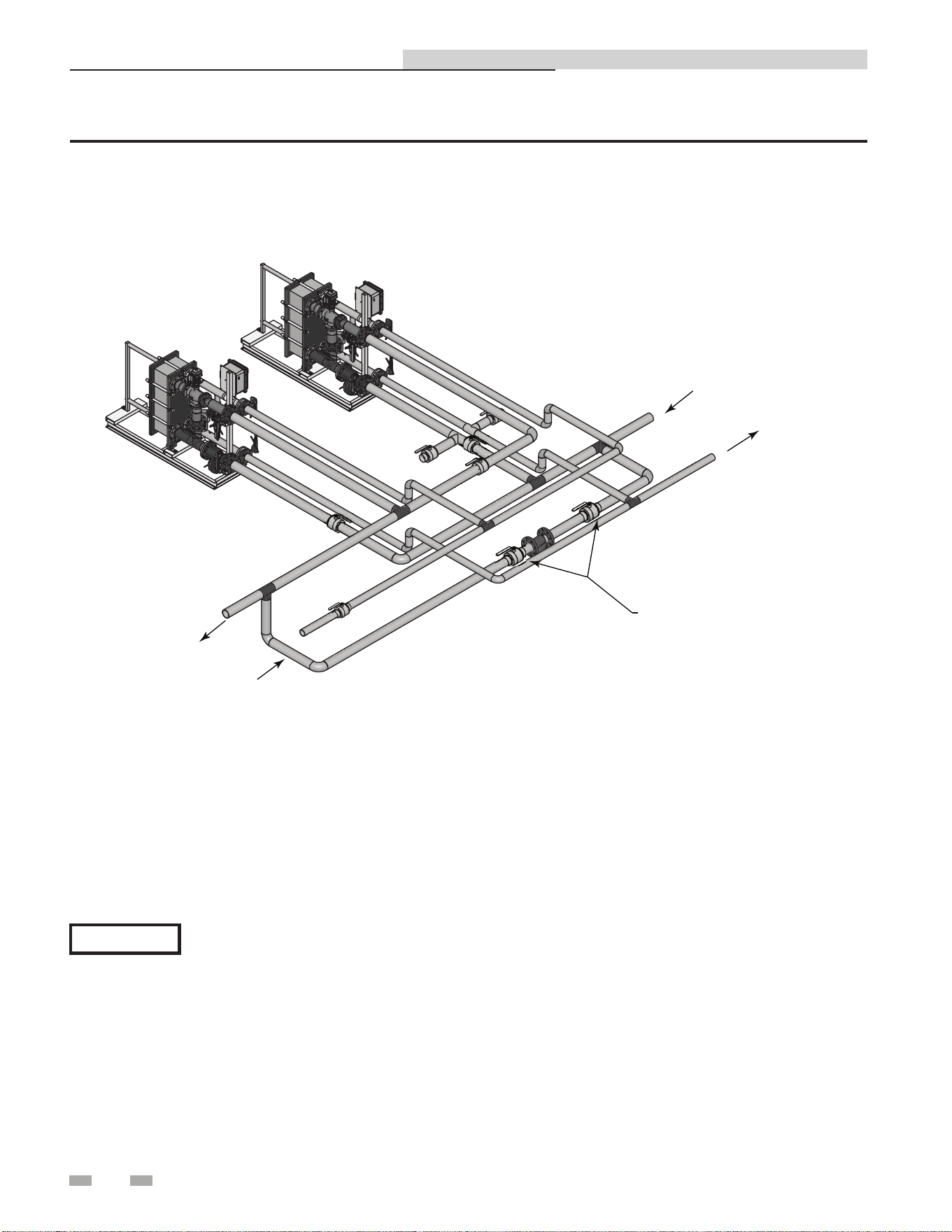
3 Hydronic piping (continued)
DIR #2000577546
HOT WATER
SUPPLY
BOILER WATER
IN
TEMPERATURE
GAUGE
COLD WATER SUPPLY
BOILER WATER OUT
Figure 3-4 Water to Water Heat Exchanger Multiple Units
Please note that these illustrations are meant to show system piping concept only, the installer is responsible
for all equipment and detailing required by local codes.
NOTICE
Indirect Plate Water Heater Installation & Service Manual
12
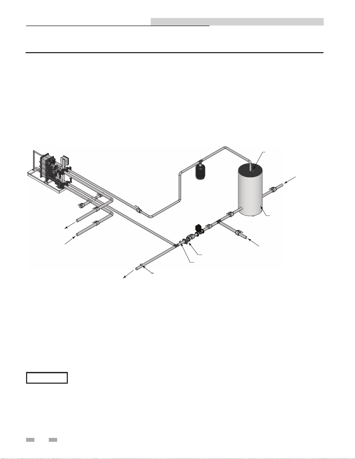
3 Hydronic piping
DIR #20005775360
TEMPERATURE GAUGE
FLOW INDICATOR
BALANCING VALVE
PUMP
EXPANSION
TANK
RELIEF VALVE
ACCUMULATOR
TANK
COLD WATER SUPPL
Y
HOT WATER SUPPLY
BOILER WATER
IN
BOILER WATER
OUT
BUILDING RETURN
Figure 3-5 Water to Water Heat Exchanger Single Unit with Accumulator Tank
Please note that these illustrations are meant to show system piping concept only, the installer is responsible
for all equipment and detailing required by local codes.
NOTICE
Indirect Plate Water Heater Installation & Service Manual
13
DIR #2000577555
ZONE PUMP
BUFFER TANK
AUTOMATIC AIR VENT
ZONE SUPPLY
ZONE RETURN
IPW WATER HEATER
Figure 3-6 Multiple Units with Boiler Side Buffer Tank as a Zone
Please note that these illustrations are meant to show system piping concept only, the installer is responsible
for all equipment and detailing required by local codes.
NOTICE
3 Hydronic piping (continued)
Indirect Plate Water Heater Installation & Service Manual
14
3 Hydronic piping
DIR #2000577549
HOT WATER SUPPLY
BOILER WATER IN
BOILER WATER
OUT
COLD WATER SUPPLY
BYPASS LINE
Figure 3-7 Multiple Units with Conventional Heating System as a Zone
Please note that these illustrations are meant to show system piping concept only, the installer is responsible
for all equipment and detailing required by local codes.
NOTICE
Indirect Plate Water Heater Installation & Service Manual
15
4 Adjustments
This section provides the adjustment procedures for the 3-way
control valve (FIG. 4-1) and the IPW electronic control system.
Prior to shipment from Lochinvar, control valve actuators are
adjusted (auto-stroked) to ensure that they properly position
the control valve from the fully-open to the fully-closed
positions. In addition, the electronic control system is adjusted
to the set point temperature specified on the sales order.
It is recommended that the following procedures be performed
to the extent necessary, prior to placing the water heater
into operation. Also, the applicable procedures MUST be
performed following replacement of the control valve or
electronic control system components to ensure that all
parameters are properly set.
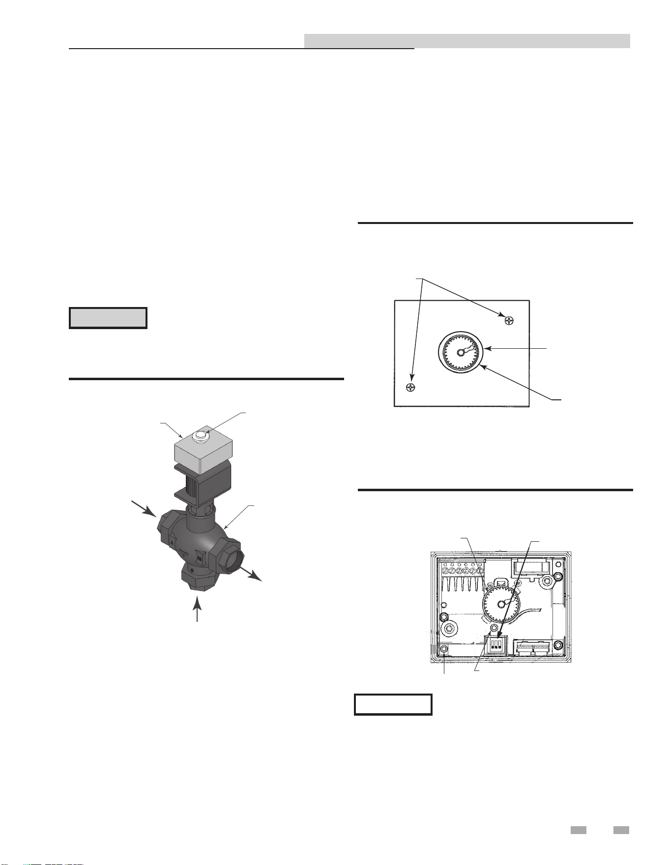
2000527529
HANDWHEEL
ELECTRONIC
MODULE
PORT A
PORT AB
VALVE BODY
PORT B
Figure 4-1 3-Way Control Valve
Control valve calibration and status indications
The control valve actuators are self-calibrating for all valve
sizes; therefore, simply proceed as follows to automatically
adjust the valve actuator:
1. Reference FIG. 4-2 and loosen the two (2) captive screws
securing the cover on the electronic module of the
control valve. Remove hand-wheel ring.
CAUTION
As a precaution, ensure that all heating
fluid (hot boiler water) shutoff valves are
fully closed prior to performing any of the
following adjustment procedures.
3-way control valve adjustment
The 3-way control valves used on all IPW models are powered by
24 VAC. For IPW applications, each 3-way valve is controlled
by a 0 to 10 VDC signal received from the temperature
controller contained in the electronic control system. A 0 VDC
signal places the control valve in the full bypass position from
port B to port AB (valve shaft up). A 10 VDC signal places the
control valve in the full flow position from port A to port AB
(valve shaft down).
COVER
SCREWS (2)
HANDWHEEL
RING
HANDWHEEL
Figure 4-2 Control Valve Electronics Module - Top View
2. Remove the electronics module cover from the valve to
access the internal components as shown in FIG. 4-3.
DIP SWITCHES
LED
AUTO-STROKE BUTTON
HANDWHEEL
Figure 4-3 Control Valve with Electronics Module Cover
Removed
When external 120 VAC power is properly
connected to the control box, 24 VAC power
is supplied to the control valve when the
control box POWER switch is set to the ON
position. The POWER switch is located on
the front of the control box.
NOTICE
3. Ensure that all three (3) DIP switches shown in FIG. 4-3
are in the OFF (Down) position as shown.
Indirect Plate Water Heater Installation & Service Manual
16
4 Adjustments
4. Set the control box POWER switch to the ON position
to apply 24 VAC power to the control valve actuator (pins
1 (G0) and 2 (G)). Ensure the valve is in the AUTO
position, the LED indicator will light green continuously
indicating that valve operation is normal (no faults).
5. Using a pin or paper clip, depress the AUTO-STROKE
button in the opening of the terminal housing (FIG. 4-3).
This will initiate calibration of the control valve.
6. During actuator calibration, the LED indicator (FIG. 4-3)
will flash green for approximately 10 seconds. The
control valve will be briefly closed and fully opened.
7. Upon successful completion of the valve calibration
process, the LED indicator will stop flashing and remain
ON continuously green.
8. The two-color (red/green) indicator is useful in
determining the operating status of the control valve.
Reference Table 4A for descriptions of the possible LED
status displays which may be encountered.
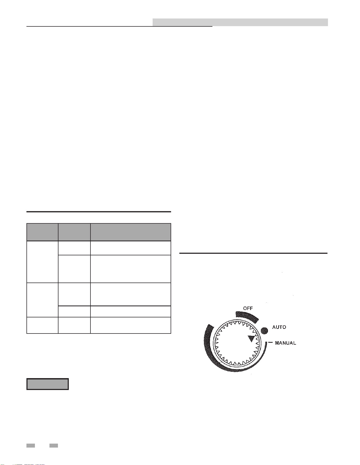
Manual control of 3-way valve - removable handwheel
to hamper tampering
If desired, the control path (A-to-AB) of the control valve can
be opened manually up to 95% of full-stroke. Reference FIG.
4-4 and proceed as follows:
1. Remove the water heater from service prior to using the
Manual Operating Mode.
2. Press the handwheel inward and rotate it clockwise to the
MANUAL position. This will disable the 0 to 10 VDC
control signal from the temperature controller. The valve
can now be mechanically rotated. The temperature control
system is now disabled. Be sure to return to the Auto Mode
prior to returning the system to heating service use (see
Step 4).
3. To disable automatic control of the valve, press the
handwheel inward and rotate it counterclockwise to the
OFF position. This will close the valve.
4. To set the valve for automatic (AUTO) operation, rotate
the handwheel to the AUTO position. The handwheel will
pop up when in the AUTO position, thereby allowing it to
be controlled by the temperature controller.
Table 4A Control Valve LED Status Indicators
LED
Display
Status Description
LED green
On
Continuously
Automatic Mode (normal, no faults)
Flashing
- Mechanically set to MANUAL
- Mechanically set to OFF
- Currently in Auto-Calibrate Mode
LED red
On
Continuously
- General fault
- General calibration fault
- Microprocessor fault
Flashing - Faulty 24 VAC supply (too low)
LED Off
- No 24 VAC supply
- Electronics module fault
9. Turn off power to the control valve by setting the control
box POWER switch to the OFF position.
10. Replace and secure the electronics module cover by
tightening the two (2) captive screws.
⚠WARNING
Manual control operation of the 3-way
valve disables the over-temperature and
power loss safety shutdown features of the
system. Manual operation is only used
for problem diagnosis. Manual operation
may cause over-heating of domestic water
and scalding of water users.
Figure 4-4 Control Valve Auto, Manual, and Off Positions
Indirect Plate Water Heater Installation & Service Manual
17
4 Adjustments (continued)
The control and the high limit are set at factory defaults. If
changes are required, the set point and high limit can be easily
changed. This is accomplished using the controls provided on
the temperature controller and the high limit switch contained
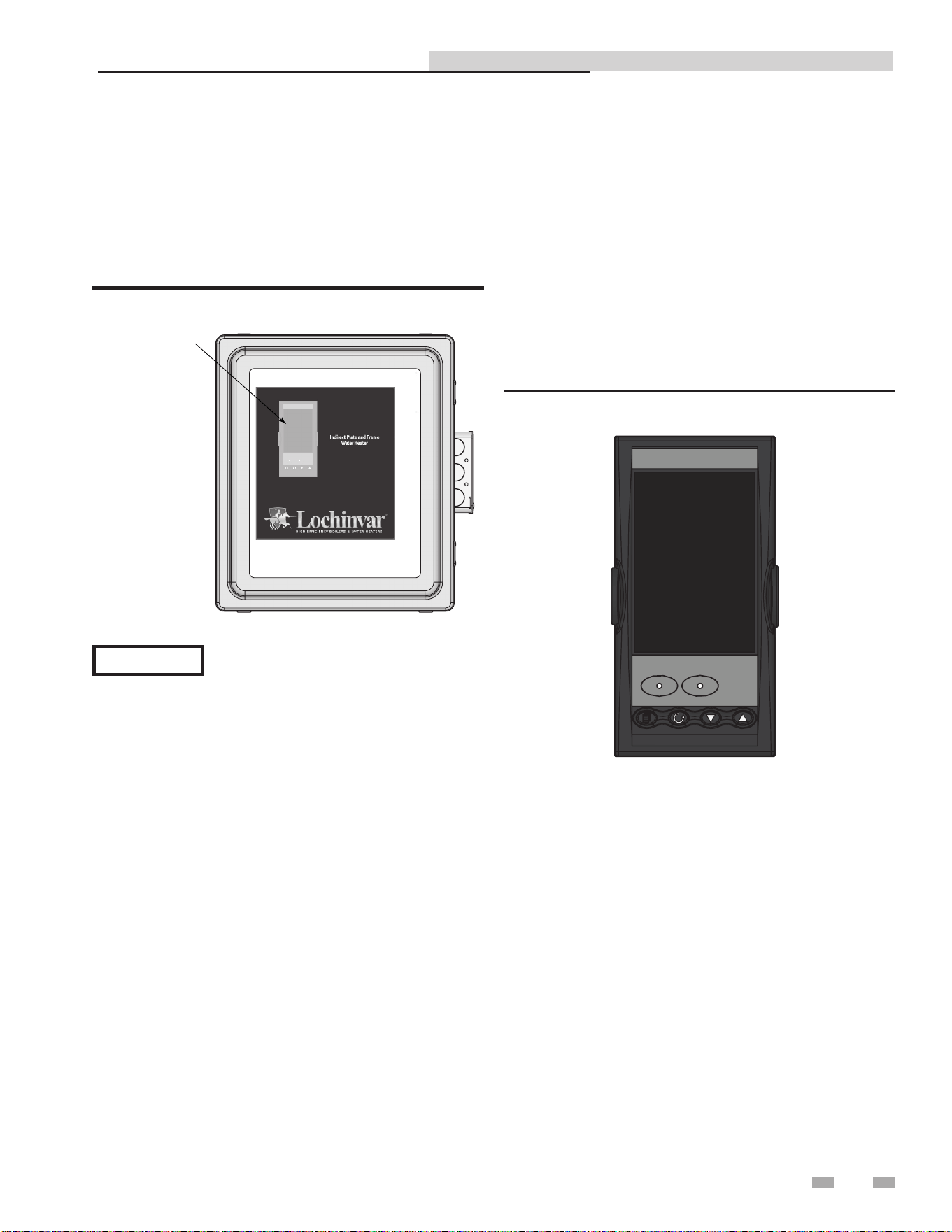
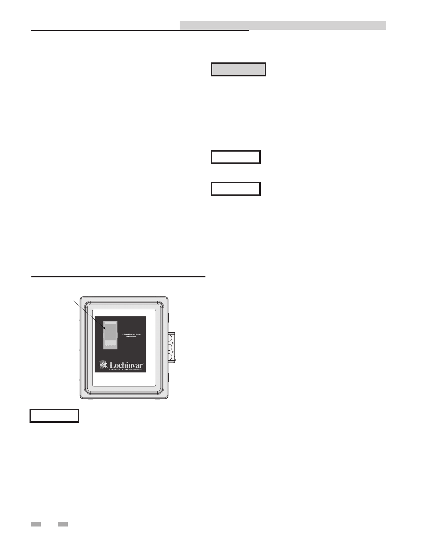
in the control box (see FIG. 4-5). The controller can be viewed
on the front door of the control box. The High Limit is inside
the panel
Figure 4-5 Control Box - Front View
When the power switch on the control box
is set to the ON position, it also energizes the
internal 24 VAC transformer in the control
box. This in turn provides 24 VAC power
to the control valve actuator, provided the
water temperature at the heater outlet is
below the high temperature limit setting.
NOTICE
Set point temperature adjustment
The set point temperature is adjusted using the controls and
displays provided on the temperature controller. These controls
and displays are illustrated and described in FIG. 4-6 and Table
4B on page 18. If necessary, set point temperature adjustment is
accomplished as follows:
1. Set the ON/OFF POWER switch on the right side to the ON
position. The temperature controller will initiate a self-
test for approximately 3 seconds. Following the self-test,
the top display will show the current outlet water temperature
of the heater above the current set point temperature stored
in memory.
2. Ensure that the temperature controller is set to AUTO
(automatic) Mode and the AUTO indicator is lit. If the
MAN indicator is lit, press the AUTO/MAN button to
toggle the mode setting.
3. If the lower display does not show the desired set point
temperature, press the p or q arrow button to
change the display to the desired value.
4. Two seconds after the p or q arrow button is
released, the display will blink to indicate that the
temperature controller (FIG. 4-6) has accepted and stored
the displayed value.
DIR #2000577456
Figure 4-6 Temperature Controller
Indirect Plate Water Heater Installation & Service Manual
DIR #2000577455
TEMPERATURE
CONTROLLER
18
4 Adjustments
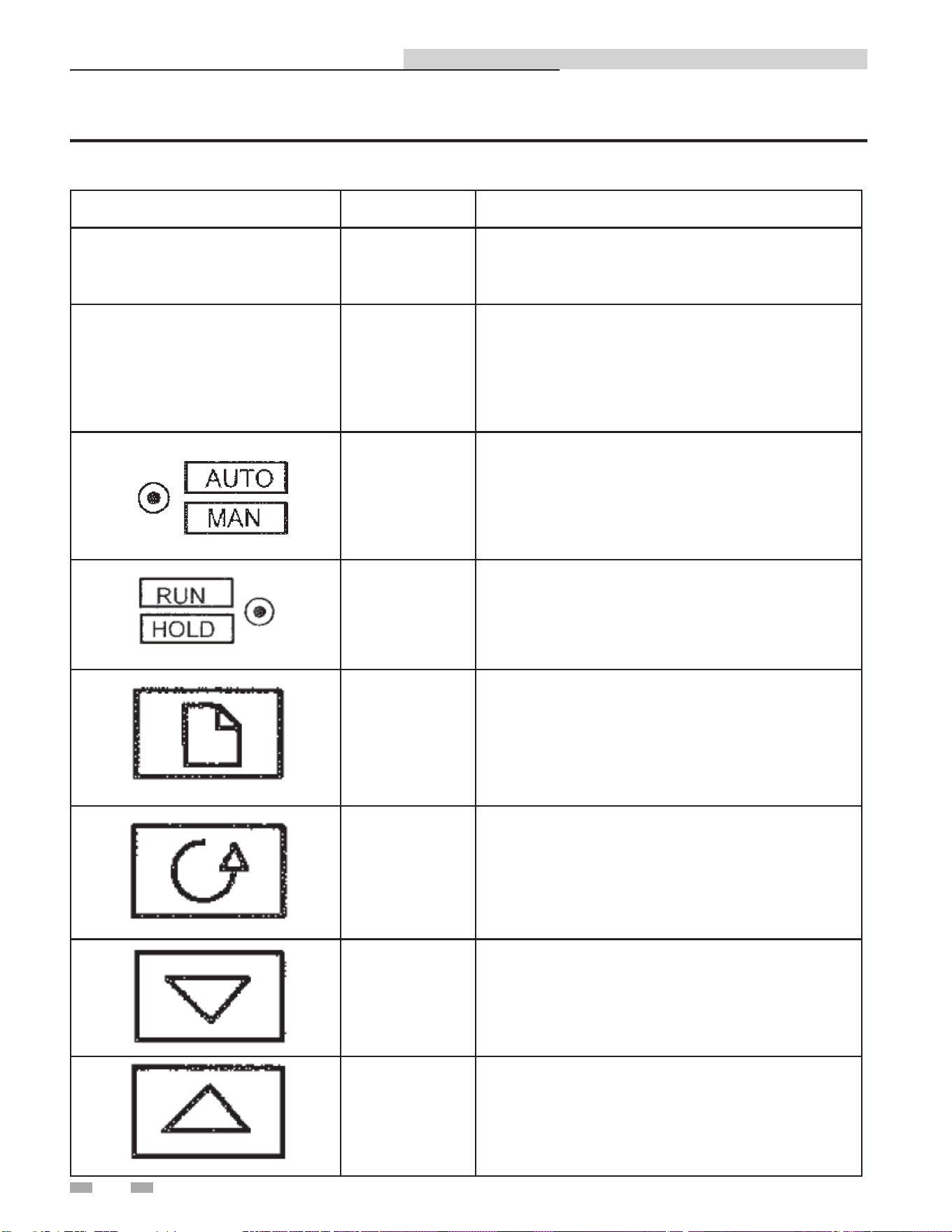
Table 4B Temperature Controller Operating Controls, Indicators and Displays
Indirect Plate Water Heater Installation & Service Manual
CONTROL or INDICATOR MEANING FUNCTION
SP
Set Point
Indicator
SP for multiplier factory set at 0.
REM
Remote Set
Point Active
Illuminates when remote set point is active.
Auto/Manual
Button and
Indicator
Not used. If "MAN" is lit in the top of the screen,
press AUTO/MAN to put the control back into
Auto Mode.
Run/Hold
Button and
Indicators
Not used for IPW applications.
(a) Page Button Press PAGE button to select new page headings.
(b) Scroll Button
Press SCROLL button to select a new parameter
on the page.
(c) Down Button
Press DOWN button to decrease an analogue
value, or to change the state of a digital value.
(d) Up Button
Press UP button to increase an analogue value,
or to change the state of a digital value.

19
5 Operating information
Electronic control overview
The primary control mechanism for the electronic control
system is an electronic process controller which is installed
in the control box. The controller utilizes feed forward and
PID (Proportional Integral Derivative) algorithms to provide
precise control of the water heater outlet temperature. Outlet
temperature control is accomplished by modulating the open/
closed position of the control valve actuator.
The controller continuously monitors the water heater outlet
temperature via an RTD located in the outlet port. The
controller also receives a signal from the temperature sensor
mounted in the mixed water inlet as shown in FIG. 3-1A. The
mixed water sensor monitors flow changes through the water
heater and provides a signal to the controller proportional to
the change in flow. The mixed water temperature provides an
instantaneous response for the specified flow range of the unit.
The controller provides a 0 - 10 VDC output signal to the
control valve actuator. This 0 - 10 VDC signal proportionally
modulates the control valve position from fully closed (0 VDC)
to fully open (10 VDC). The control signal varies as necessary
to maintain the set point temperature programmed into the
controller. Under normal conditions, the IPW water heater
outlet temperature is maintained within + 4°F of the desired set
point based on a load change of 50% or less.
Over-temperature control and safety
features
The control box contains an over-temperature switch which
continuously monitors the outlet water temperature of the
heater. Normally, the over-temperature switch is set to 20°F
above the set point temperature for the water heater. If the
programmed over-temperature limit is exceeded, the over-
temperature switch is activated. This in turn disconnects
power from the control valve actuator moving the control valve
to the full bypass position (B- AB). It should be noted that
the over-temperature switch has a slightly slower response to
temperature changes than the temperature controller.
The control valve actuator also incorporates a "Fail Safe" feature
which automatically closes the valve if there is a loss of the 0 - 10
VDC control signal or loss of input power. The 24 VAC power
supply transformer has an integral 3 amp circuit breaker to
protect the control valve electronics.
An electronic control system coupled with a control valve
results in a highly responsive system which provides virtually
constant hot water flow at the selected set point temperature.
Accessories included with the IPW water heater include:
• Boiler water and domestic water Y-strainers with blow-
down valves
• Pressure & Temperature relief valve
• Isolation valves and domestic water drain valve
• Integral domestic water circulator pump
The following paragraphs provide a top-level functional
overview of system operation.
Sequence of operation
The cold water enters the heat exchanger through the inlet
connection and strainer. Cold water flows through the plate
heat exchanger, where it is heated by hot boiler water, and
then discharged through the Domestic Hot Water (DHW)
outlet connection. A portion of hot water is mixed with the
cold water entering the heater.
Boiler water supplied to the heat exchanger passes through
the inlet connection and strainer. The boiler water heats
the colder domestic water, and is then discharged through
the boiler water outlet connection. The boiler water flow is
controlled by a 3-way valve.
For IPW double-wall heat exchanger models, heat transfer
plates are positioned together to form one assembly with
an air space between them. This protects against leakage
of boiler water into the domestic water. If one of the plates
should develop a leak (boiler water or domestic water,
whichever is leaking), the water will enter the air space and
exit to the atmosphere. It will flow through leak detection
channels alerting an operator that a leak has occurred.
Indirect Plate Water Heater Installation & Service Manual
20
6 Wiring
Electrical wiring connections
The control box and all other electronic control system
components are installed on the IPW water heater prior to
shipment from the factory. Therefore, electrical connections
to the electronic control system basically consist of connecting
external AC power to the electronic control system control
box. The system can be powered by a single-phase AC voltage
of 120 VAC, 60 Hz. However, if the electronic control system
was ordered with the ModBus Communication option,
several additional signal lead connections will need to be
made inside the control box. These signal leads will permit
the electronic control system to be controlled by an external
Energy Management System (EMS), Building Automation
System (BAS), or computer. Proceed as follows:
1. Open the junction box on the side of the control box.
2. Route the power wiring harness into the junction box
through one of the knockouts as shown in FIG. 6-1.
3. Connect 120V power supply to the wires in the junction
box:
• Black - Live
• White - Neutral
• Green - Ground
Use a minimum of 14 AWG wire for AC
power wiring connections to the electronic
control system control box.
NOTICE
4. If ModBus is not used, no further steps are required for
the IPW. If no further connections are required, re-secure
the junction box door (FIG. 6-1).
The complete wiring diagram for the IPW
electronic control system is provided in
Section 11 of this manual.
NOTICE
Lochinvar recommends that shielded,
twisted-pair cable be used for
communication wiring.
NOTICE
Indirect Plate Water Heater Installation & Service Manual
Figure 6-1 Junction Box
DO NOT route ModBus communication
wiring in the same conduit as power
wiring. Attempting to do so may result
in excessive noise on the signal lines.
Also, ensure that the RS232 or RS485
signal cable connections do not exceed
the following lengths:
RS232 Cable: 50 feet maximum
RS485 Cable: 4,000 feet maximum
⚠CAUTION
DIR #2000577455
TEMPERATURE
CONTROLLER
7 ModBus
Indirect Plate Water Heater Installation & Service Manual
Installation Procedure
1. Turn OFF the main electrical power to the appliance.
2. Open the control box door by loosening the screws
clamping the door closed.
3. Connect wires to the control following the diagram in
Figure 7-1.
4. Close the control box door.
5. Turn on the main electrical power.
7. Configure the control per this manual and resume
operation.
Figure 7-1_Harness Connections
A
B
SHIELD
1A
1B
1C
1D
2A
2D
2C
2B
3A
3B
3C
3D
IO Module 3
IO Module 2
IO Module 1
Comms Channel 2
Comms Channel 1
HA
HB
HC
HD
HF
HE
JA
JB
JC
JD
JE
JF
L
V-
V+
VI
AC
AB
AA
N
D8
LB
LC
DIR# 2000535637 00
21
22
7 ModBus
Indirect Plate Water Heater Installation & Service Manual
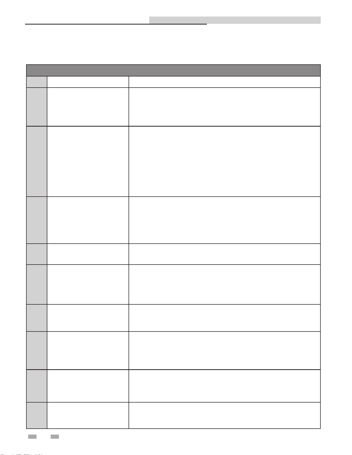
MODBUS Exception Codes
Code Name Meaning
01 ILLEGAL FUNCTION
The function code received in the query is not an allowable action for the server
(or slave). This may be because the function code is only applicable to newer
devices, and was not implemented in the unit selected. It could also indicate that
the server (or slave) is in the wrong state to process a request of this type, for
example because it is unconfigured and is being asked to return register values.
02 ILLEGAL DATA ADDRESS
The data address received in the query is not an allowable address for the
server (or slave). More specifically, the combination of reference number and
transfer length is invalid. For a controller with 100 registers, the PDU addresses
the first register as 0, and the last one as 99. If a request is submitted with a
starting register address of 96 and a quantity of registers of 4, then this request
will successfully operate (address-wise at least) on registers 96, 97, 98, 99. If
a request is submitted with a starting register address of 96 and a quantity of
registers of 5, then this request will fail with Exception Code 0x02 “Illegal Data
Address” since it attempts to operate on registers 96, 97, 98, 99 and 100, and
there is no register with address 100.
03 ILLEGAL DATA VALUE
A value contained in the query data field is not an allowable value for server
(or slave). This indicates a fault in the structure of the remainder of a complex
request, such as that the implied length is incorrect. It specifically does NOT
mean that a data item submitted for storage in a register has a value outside the
expectation of the application program, since the MODBUS protocol is unaware of
the significance of any particular value of any particular register.
04 SLAVE DEVICE FAILURE
An unrecoverable error occurred while the server (or slave) was attempting to
perform the requested action.
05 ACKNOWLEDGE
Specialized use in conjunction with programming commands. The server
(or slave) has accepted the request and is processing it, but a long duration of
time will be required to do so. This response is returned to prevent a timeout error
from occurring in the client (or master). The client (or master) can next issue a Poll
Program Complete message to determine if processing is completed.
06 SLAVE DEVICE BUSY
Specialized use in conjunction with programming commands. The server
(or slave) is engaged in processing a long -- duration program command. The
client (or master) should re-transmit the message later when the server (or slave)
is free.
08 MEMORY PARITY ERROR
Specialized use in conjunction with function codes 20 and 21 and reference type
6, to indicate that the extended file area failed to pass a consistency check. The
server (or slave) attempted to read record file, but detected a parity error in the
memory. The client (or master) can retry the request, but service may be required
on the server (or slave) device.
0A GATEWAY PATH UNAVAILABLE
Specialized use in conjunction with gateways, indicates that the gateway was
unable to allocate an internal communication path from the input port to the
output port for processing as the request. Usually means that the gateway is
misconfigured or overloaded.
0B
GATEWAY TARGET DEVICE
FAILED TO RESPOND
Specialized use in conjunction with gateways, indicates that no response was
obtained from the target device. Usually means that the device is not present on
the network.
ModBus Exception Codes
7 ModBus (continued)
Indirect Plate Water Heater Installation & Service Manual
Primary Data Tables
Table Data Type Read / Write
Input Registers 16-Bit Word Read Only
Holding Registers 16 Bit Word Read / Write
Input Registers
Address Description Default Unit Min. Max. Resolution
30004 Outlet Temperature ---- Degrees Fahrenheit -328 1562 0.1
30006 Inlet Temperature ---- Degrees Fahrenheit -328 1562 0.1
30008 Outlet Voltage (Valve Position) ---- Volts 0 10 0.01
Holding Registers
40002 Setpoint 118 Degrees Fahrenheit 90 180 0.01
Memory Map
23
RS-485 Communication Bus
• Maximum Length = 4000 feet
• Cable Specification = 24 AWG / A,B (twisted pair) and GND Shielded, with characteristic Impedance = 120 ohm
• Maximum Load = 32 units (32 nodes)
NOTE: Cable must be terminated with 120 ohm impedance matching resistor on each end.
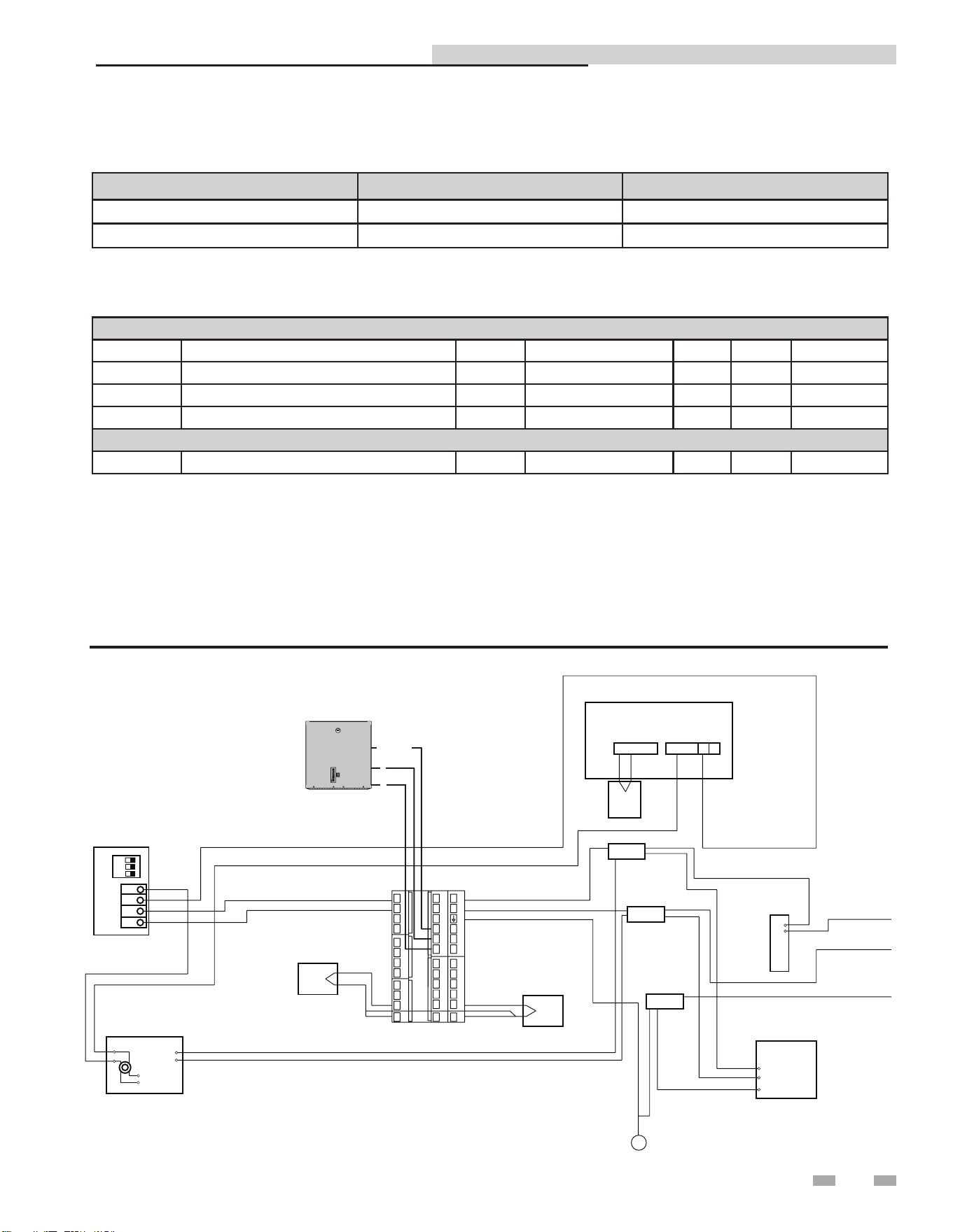
Physical Wiring
Figure 7-2_Wiring Diagram
Mixed Inlet
Temperature
Domestic Water
Outlet Temperature
Auto Reset High Limit
Splice
Splice
Splice
Internal
Recirculation
Pump 120
VAC 60 Hz
S
w
i
t
c
h
RTD
RTD
Ground Lug
BLUE
YELLOW
BLUE
BLACK
WHITE
GREEN
ORANGE
ORANGE
GRAY
BLACK
WHITE
GREEN
GREEN
ORANGE
ORANGE
BLACK
BLACK
WHITE
GREEN
BLACK
G
R
E
E
N
W
H
I
T
E
ON
3
2
1
1
2
3
4
+
_
OUTPUT
INPUT
L
N
L
N
2
1
COM 1
2
WHITE +-RED
THERMO
COUPLE
(OUTLET)
Boiler Water
Modulating Valve
Mounted Inside Control Box
Transformer 120 VAC/ 24 VAC
BUILDING
MANAGEMENT
SYSTEM
A
B
SHIELD
1A
1B
1C
1D
2A
2D
2C
2B
3A
3B
3C
3D
IO Module 3
IO Module 2
IO Module 1
Comms Channel 2
Comms Channel 1
HA
HB
HC
HD
HF
HE
JA
JB
JC
JD
JE
JF
L
V-
V+
VI
AC
AB
AA
N
D8
LB
LC
DIR# 2000535601 00

7 ModBus
Indirect Plate Water Heater Installation & Service Manual
Procedure to change ModBus address
1. Press and hold Page ( ) until "Access Go To
Level 1" appears.
2. Press the button twice to get to Level 3.
3. Wait until "Pass Code 0" appears.
4. Press the button three (3) times to set the pass code
to 3.
5. Wait until " Pass" appears.
6. Press Page ( ) until "Comms H" appears.
7. Press the button five (5) times to access "Address
1."
8. Use the buttons to adjust the address.
9. Press and hold the Page ( ) and Next ( ) buttons
together until the main screen appears.
10. Press and hold Page ( ) until "Access Go To
Level 3" appears.
11. Press the button twice to return to Level 1.
12. Press Page ( ).
Should you encounter problems communicating over
ModBus, the following items should be checked in this order:
1. Physical Layer
2. Communications Configuration and Port Settings
3. ModBus Error Codes
Physical Layer
1. Check that all components have power (IPW, Gateway,
BAS Master)
2. Check all wire lengths. Are any drops too long?
3. Check proper shield grounding
4. Check A, B terminal connections
5. Check for Terminating Resistors (120 ohms)
6. Check for broken wires
Communications
1. Check Baud Rate (19200)
2. Check Parity (NO)
3. Check Slave ID
4. Check Port Setting on Master, Gateway, and Computers
ModBus Error Codes
1. Check ModBus communication for error codes (see page
22 for ModBus Exception Codes)
2. Check ModBus RTU
3. Check Slave ID
4. Check ModBus Command
Troubleshooting
24

25
8 Start-up
Introduction
This section provides the pre-optional checks, initial start-up
and operating procedures for the IPW water heater.
Pre-operational checks and procedures
All IPW installation procedures provided in Section 2
- Prepare Water Heater must be fully completed prior
to performing Pre-Operational checks. In addition, the
following items should be checked:
1. Ensure that external single-phase AC power at 120
VAC/60 Hz is properly connected to the electronic
control system control box.
2. Open the isolation valve in the cold water inlet line to the
IPW water heater.
3. Verify that the electronic control system temperature
controller set point and over-temperature switch alarm
limit have been properly set using the procedures in
Section 4 - Adjustments.
4. The air vent, located in the top of the manifold, allows
air to escape during the fill process (a hissing sound may
be heard). If a hissing sound is not heard through the air
vent, close the air vent cap and then open it two (2) full
turns counterclockwise. DO NOT remove the air vent
cap.
5. When hissing sound from the air vent stops, carefully
open the pressure and temperature (P & T) relief valve to
vent any remaining air.
6. Close the P & T relief valve when the heater is full.
DO NOT operate equipment exceeding
design conditions as specified on the
nameplate.
The IPW must never be subjected to
pressure greater than the maximum
differential pressure specified on the
nameplate.
Sudden rises in pressure may cause leakage
or damage to plates or gaskets of double-
wall models.
Fluids MUST BE gradually introduced
to the unit. Failure to do so can cause
damage to heat exchanger plates. When
the unit is empty or cold, DO NOT admit
hot fluid to the unit suddenly. When unit
is hot, DO NOT shock with cold fluid.
⚠WARNING
⚠ CAUTION
Initial start-up
In order to prevent a possible over-temperature condition
during initial start-up, Lochinvar recommends that the
following steps be performed in the order specified:
1. Set the POWER switch on the front of the box to the
ON position. This will provide power to the complete
electronic control system and control valve. When power is
initially applied, the electronic control system temperature
controller automatically performs a self-test sequence for
approximately three (3) seconds. Proceed immediately to
the next step.
2. Upon completion of the self-test, the temperature controller
will show the present water heater outlet temperature
in the upper display and the set point temperature is
displayed right below that.
3. Open the stop valve in the building recirculation system, if
employed.
4. Open the isolation valve in the hot water outlet line.
Connect a hose to the field-piped hose connection (see
piping diagrams in Section 3- Hydronic Piping or open
several hot water fixtures in the building to ensure water
flow through the heater.
5. Slowly open the isolation valves in the water inlet and
water outlet connections of the heater.
6. When in the AUTO Mode, the electronic control system
will stabilize at the selected set point temperature. Once
stabilized, the electronic control system is set for unattended
operation with no further operator intervention. The
control may take several minutes to stabilize. Temperature
may vary during this time. Stabilized when bottom PV is
near bottom SP (0).
7. Close the hose connection or hot water fixtures opened in
Step 4.
8. During start-up of double-wall models, there may be some
evidence of leakage prior to the plates and gaskets reaching
their working temperature. If leakage continues, contact
the factory for assistance.
Indirect Plate Water Heater Installation & Service Manual

26
8 Start-up
Checking mixed inlet temperature
If desired, the water heater mixed inlet temperature can be
monitored using the controls and displays on the temperature
controller. This is accomplished as follows:
1. Press the PAGE button ( ) until MATH 2 is displayed.
2. Press the UP button ( ) until the right side value is 5.
3. Press the SCROLL button ( ) until INPUT 2 is shown,
this is the mixed inlet.
4. When INPUT 2 is shown in the upper display, the
lower display will show the water heater mixed inlet
temperature. The temperature will be displayed for
several seconds and then the controller will revert to the
default displays (outlet water temperature and set point).
Shutting down the system
To shut down the IPW for a short period of time, simply turn
OFF power and close the isolation valves as described in Steps
1 and 2 below. However, if the IPW will shut down for an
extended period of time, it will be necessary to drain the unit
using the appropriate steps listed below for the type of heat
exchanger used (double-wall). Proceed as follows:
1. Turn OFF the POWER switch on the side of the electronic
control system control box.
2. Close all four (4) of the isolation ball valves.
3. Connect a drain hose to the strainer on the boiler water side
of the piping assembly. Open the valve on the strainer and
drain the water from the heater.
4. Next, connect a hose to the drain valve on the DHW side
of the piping assembly.
5. Open the drain valve to drain the domestic water from the
heater.
6. It is also advisable to separate and clean the plates. Reference
the CD provided with the IPW for detailed instructions on
cleaning the plates.
7. To place the IPW back in service, fill the unit and perform
the pre-operational checks and start-up procedures
described on page 25.
Indirect Plate Water Heater Installation & Service Manual
9 Maintenance
Maintenance and annual startup
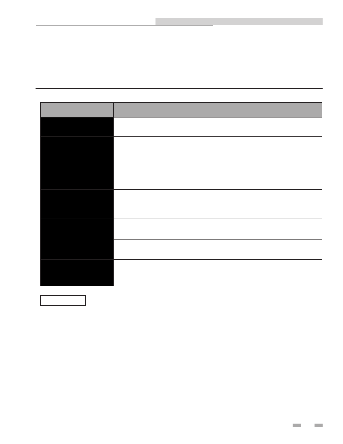
Table 9A Scheduled Maintenance Actions
Interval Maintenance
Weekly
Double-Wall Only: Check plate packs for leakage.
Quarterly
Every 3 months, check the operation of the over-temp switch in the electronic
control system control box.
Quarterly / Semi-
Annually
After the first 3 months, check the operation of the control valve in the boiler
water piping. Then check operation every 6 months.
Semi-Annually
Every 6 months, check the strainers on both the boiler water and domestic water
piping side.
Annually
Once each year, check the temperature sensors.
Once each year, check the operation of the recirculation pump.
Periodic
Periodic cleaning of the heat exchanger may be necessary, depending on
conditions and settings.
27
The IPW water heater requires regular routine maintenance to keep the unit operating at optimum efficiency. Lochinvar
recommends that the tasks listed in Table 9A - Scheduled Maintenance Actions, be performed at the periodic intervals specified.
Indirect Plate Water Heater Installation & Service Manual
NOTICE
For specific maintenance instructions reference the CD provided with the IPW.
9 Maintenance
Indirect Plate Water Heater Installation & Service Manual
Strainers - inspection and replacement
The strainers are installed upstream of the energy source
shutoff valve for the main traps. These strainers must be
blown down periodically (approximately every three (3) to six
(6) months) to prevent the build up of any sediment.
⚠WARNING
The combination of electricity and water
can pose a very dangerous situation. Turn
off / disconnect all electric power before
attempting any maintenance procedure.
1. Follow Steps 1 through 5 of the shutdown procedure
(page 26) to take the unit off-line before attempting to
replace the energy source strainers.
2. The location of the strainers can differ between packages.
3. Carefully break the line connections on the inlet side of
both strainers.
4. Carefully break the line connection on the outlet side of
the strainers.
5. Remove and examine the strainers.
Oiled bearing circulators
1. The circulator shipped with the IPW water heater is
water-lubricated. No oiling is required.
2. Check other circulators in the system. Oil any circulators
requiring oil, following circulator manufacturer’s
instructions. Over-oiling will damage the circulator.
Safety relief valves should be re-inspected
AT LEAST ONCE EVERY THREE YEARS,
by a licensed plumbing contractor or
authorized inspection agency, to ensure
that the product has not been affected by
corrosive water conditions and to ensure
that the valve and discharge line have not
been altered or tampered with illegally.
Certain naturally occurring conditions may
corrode the valve or its components over
time, rendering the valve inoperative. Such
conditions are not detectable unless the
valve and its components are physically
removed and inspected. This inspection
must only be conducted by a plumbing
contractor or authorized inspection agency,
not by the owner. Failure to re-inspect the
water heater relief valve as directed could
result in unsafe pressure buildup, which can
result in severe personal injury, death, or
substantial property damage.
Following installation, the valve lever must
be operated AT LEAST ONCE A YEAR to
ensure that waterways are clear. Certain
naturally occurring mineral deposits may
adhere to the valve, rendering it inoperative.
When manually operating the lever, water
will discharge and precautions must be taken
to avoid contact with hot water and to avoid
water damage. Before operating lever, check
to see that a discharge line is connected to
this valve directing the flow of hot water
from the valve to a proper place of disposal.
Otherwise severe personal injury may result.
If no water flows, valve is inoperative. Shut
down the water heater until a new relief
valve has been installed.
2. After following the above warning directions, if the relief
valve weeps or will not seat properly, replace the relief valve.
Ensure that the reason for relief valve weeping is the valve
and not over-pressurization of the system due to expansion
tank waterlogging or undersizing.
⚠WARNING
⚠WARNING
Periodic cleaning of heat exchanger
For a detailed description of the following
maintenance tasks, reference the CD provided with
the unit:
• De-scaling the heat exchanger
• Heat exchanger replacement
Check water heater relief valve
1. Inspect the relief valve and lift the lever to verify flow.
Before operating any relief valve, ensure that it is piped
with its discharge in a safe area to avoid severe scald
potential. Read Section 3 - Hydronic Piping before
proceeding further.
ISOLATION VA LVES
(4 PLACES)
OUTLET RTD
INLET RTD
P & T RELIEF VALVE
BOILER WATER STRAINER
W/BLOW-DOWN VALVE
DOMESTIC WATER STRAINER
W/BLOW-DOWN VALVE
DIR #2000577647
Figure 9-1 Domestic Water Side - Partial View
28
29
10 Troubleshooting
Table 10A Troubleshooting Chart - No Display
FAULT CAUSE CORRECTIVE ACTION
No Display
No 120 VAC supplied to the unit
- Check external line switch, fuse, or breaker.
- Ensure On/Off switch is in the ON position.
- Check 120 VAC through the On/Off switch.
- Check wiring harness connection between external
power and control module.
No voltage through the switch - Replace switch.
Bad control module - Replace control module.
Low Outlet
Water Temp
Modulating valve lost calibration
- Remove cover on modulating valve electronics and
press the recessed calibration button to re-calibrate
the valve.
Boiler water supply temperature or flow
has dropped below requirement to satisfy
demand
- Ensure ball valves are open fully.
- Ensure boiler water flow matches what is specified in
the sizing table.
- Ensure boiler side Y strainers are not clogged.
Control module not supplying 0 - 10 VDC
control signal to valve
- Ensure the valve is wired correctly by referencing the
wiring diagram on page 32 of this manual.
Modulating valve is not in AUTO Mode - Rotate valve handle until it is in AUTO Mode.
No 24 VAC power supplied to modulating
valve
- Ensure the valve is wired correctly by referencing the
wiring diagram on page 32 of this manual.
- Ensure the transformer is connected to the harness
correctly and its built-in circuit breaker has not tripped.
Heat exchanger is improperly sized for load
- Reduce load on heat exchanger or re-size heat
exchanger.
Heat exchanger scaled on boiler side - Clean and de-scale heat exchanger.
High limit is tripped
- Ensure high limit is set correctly so that power to the
valve will be restored when the temperature returns to
a low enough value.
High Outlet
Water Temp
Modulating valve is not in AUTO Mode - Rotate valve handle until it is in AUTO Mode.
Modulating valve lost calibration
- Remove cover on modulating valve electronics and
press the recessed calibration button to re-calibrate
the valve.
Heat exchanger scaled on DHW side - Clean and de-scale heat exchanger.
Temperature
Swings
Outside
Specified
Range
Pump not functioning
- Ensure pump is wired correctly by referring to the
wiring diagram on page 32 of this manual.
- Replace pump if faulty.
RTD or RTD harness not connected or
malfunctioning
- Ensure harness is connected and wired correctly
by referring to the wiring diagram on page 32 of this
manual.
- Check RTD resistance by using the chart on page 30
to ensure RTD is functional.
- Replace RTD or harness if faulty.
"S.Br"
Displayed
RTD or RTD harness not connected or
malfunctioning
- Ensure harness is connected and wired correctly
by referring to the wiring diagram on page 32 of this
manual.
- Check RTD resistance by using the chart on page 30
to ensure RTD is functional.
- Replace RTD or harness if faulty.
Indirect Plate Water Heater Installation & Service Manual
30
10 Troubleshooting
Table 10B - Resistance vs. Temperature
Temperature
(°F)
Resistance
(Ohms)
-328 18.52
-310 22.83
-292 27.10
-274 31.34
-256 35.54
-238 39.72
-220 43.88
-202 48.00
-184 52.11
-166 56.19
-148 60.26
-130 64.30
-112 68.33
-94 72.33
-76 76.33
-58 80.31
-40 84.27
-22 88.22
-4 92.16
14 96.09
32 100.00
Checking temperature sensors
The temperature sensors (inlet and outlet water) are resistance type devices. The following tables show the correct values for the
sensors at various temperatures. Use an ohmmeter to read the resistance of the sensor at a known temperature. If the resistance
of the sensor does not closely match its corresponding table, replace the sensor.
Indirect Plate Water Heater Installation & Service Manual
Temperature
(°F)
Resistance
(Ohms)
50 103.90
68 107.79
86 111.67
104 115.54
122 119.40
140 123.24
158 127.08
176 130.90
194 134.71
212 138.51
230 142.29
248 146.07
266 149.83
284 153.58
302 157.33
320 161.05
338 164.77
356 168.48
374 172.17
392 175.86
31
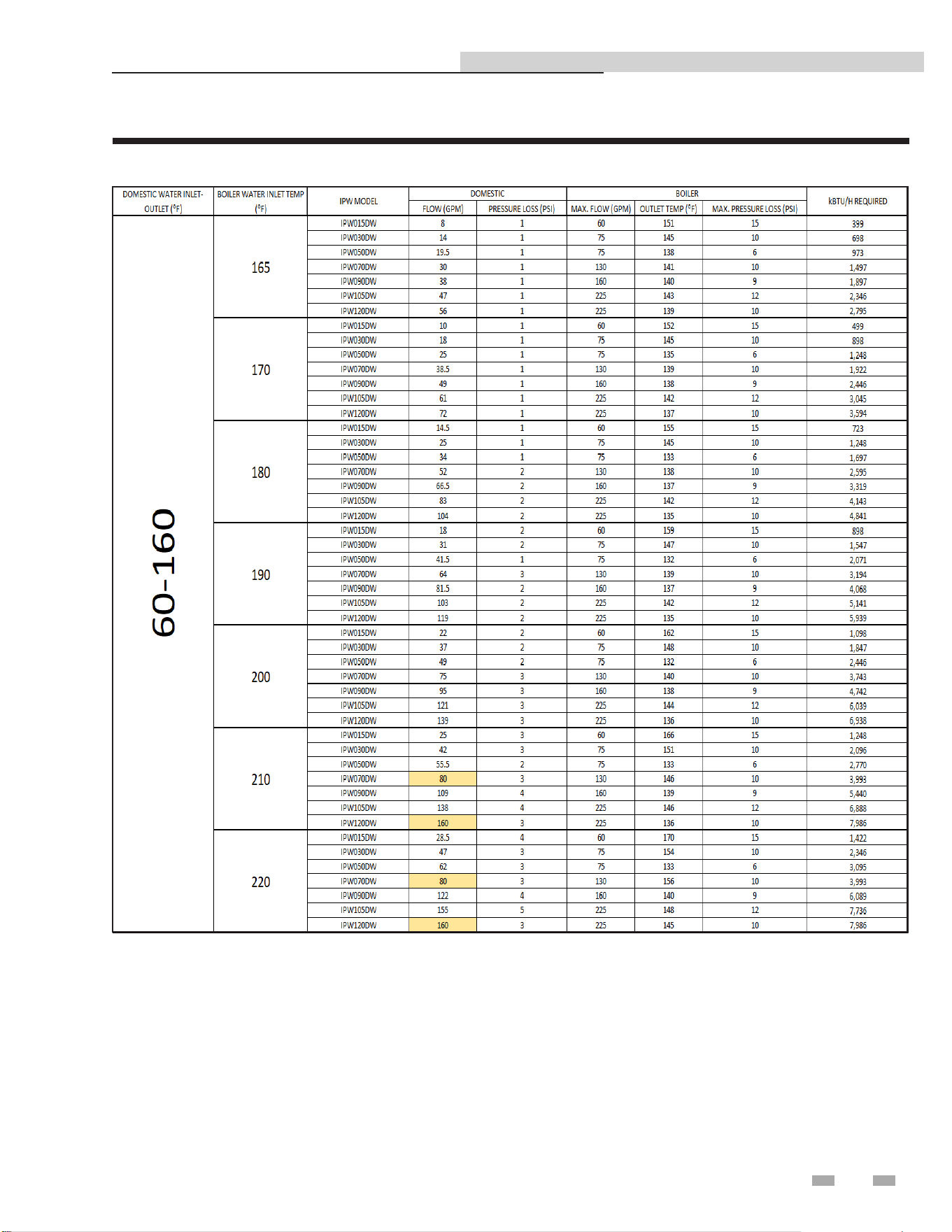
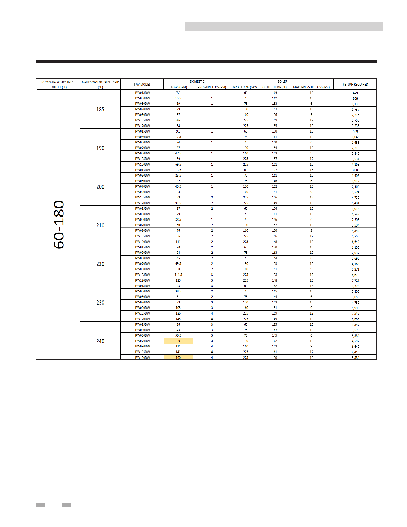
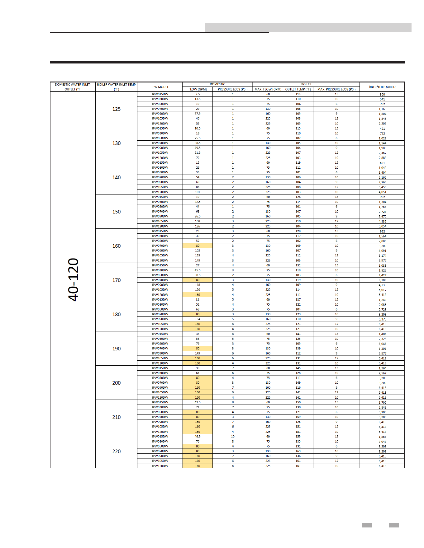
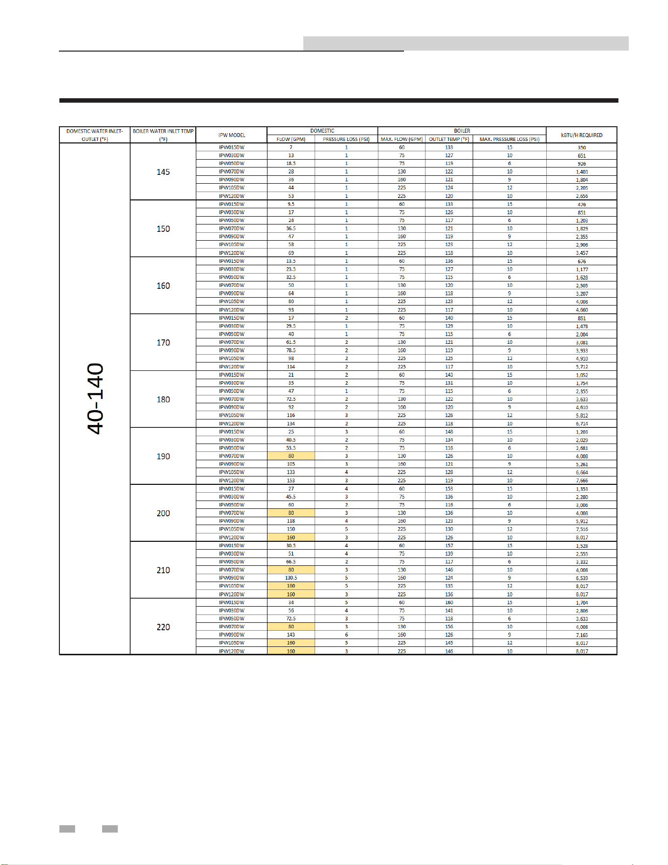
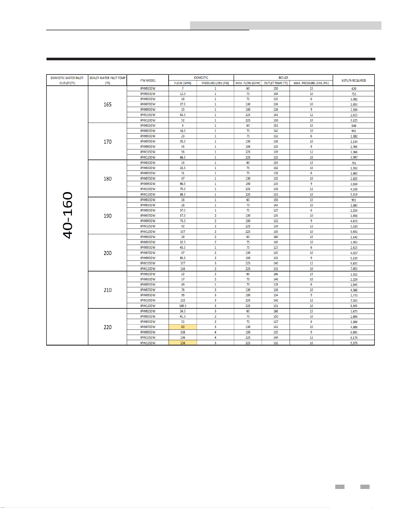
11 Sizing data
Indirect Plate Water Heater Installation & Service Manual
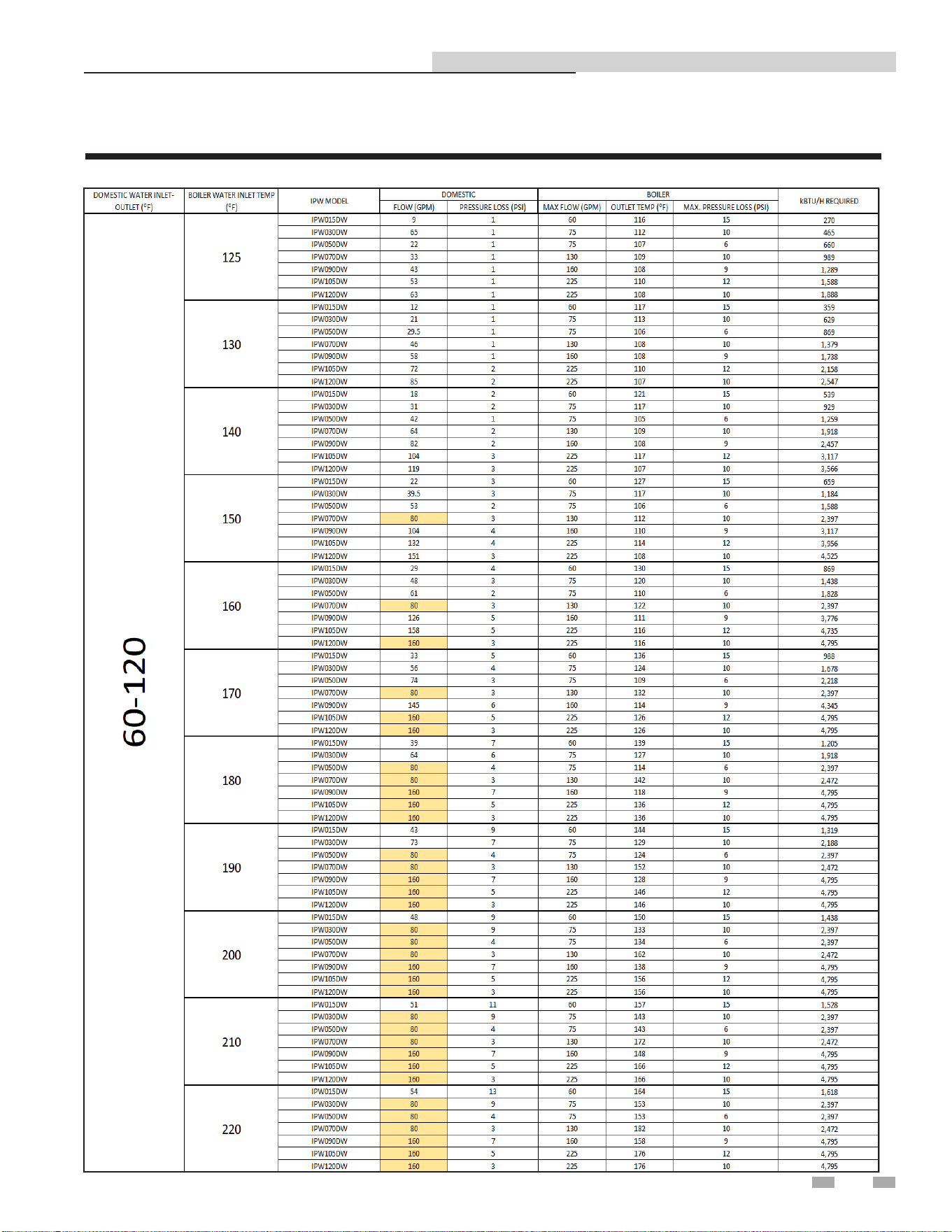
How to Properly Size Your Indirect Plate Water Heater
NOTE: Highlighted items are limited by the maximum ow velocity through the piping.
Table 11A Sizing Chart _ 60 - 120
32
11 Sizing data
Indirect Plate Water Heater Installation & Service Manual
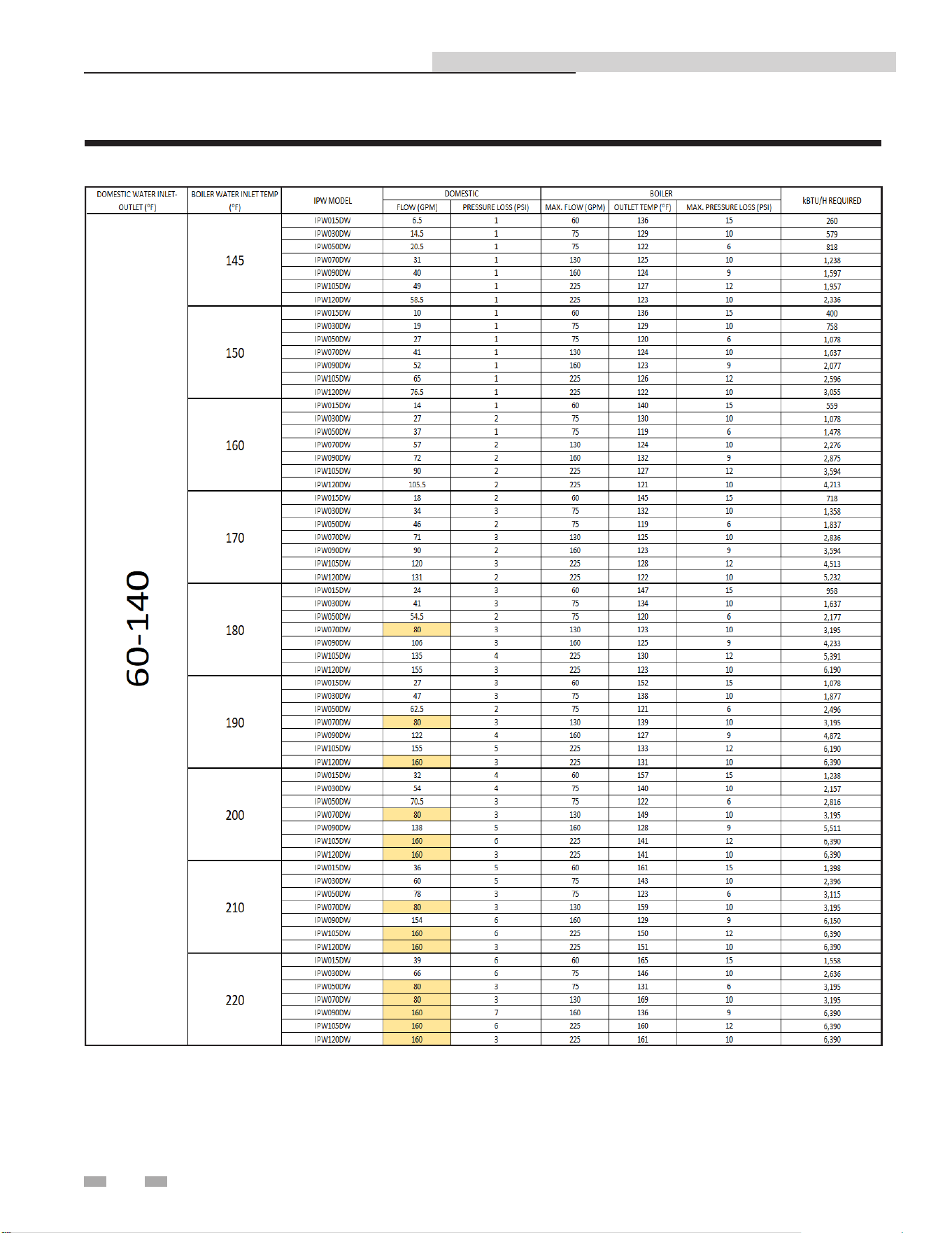
Table 11B Sizing Chart _ 60 - 140
NOTE: Highlighted items are limited by the maximum ow velocity through the piping.
33
11 Sizing data (continued)
Indirect Plate Water Heater Installation & Service Manual
Table 11C Sizing Chart _ 60 - 160
NOTE: Highlighted items are limited by the maximum ow velocity through the piping.
34
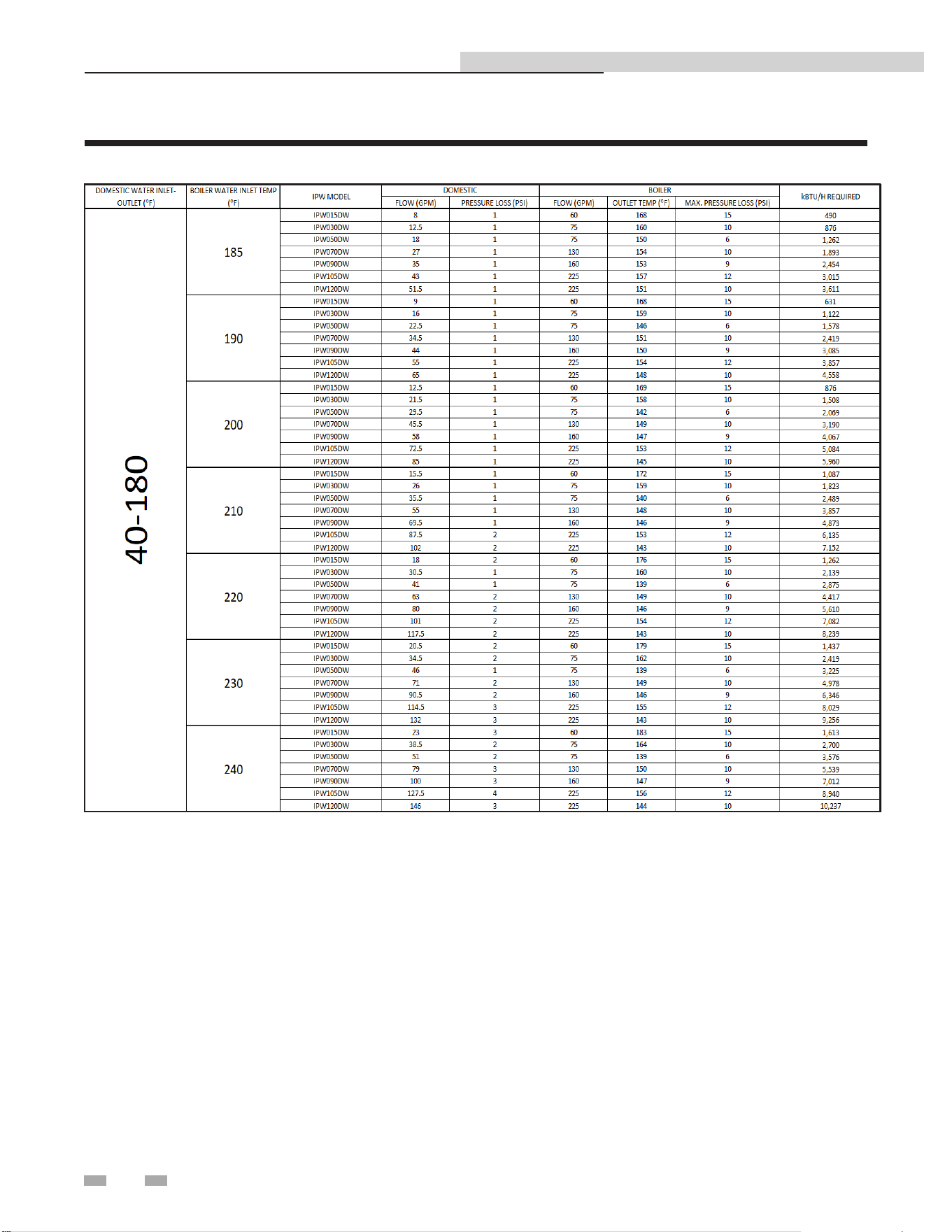
11 Sizing data
Indirect Plate Water Heater Installation & Service Manual
NOTE: Highlighted items are limited by the maximum ow velocity through the piping.
Table 11D Sizing Chart _ 60 - 180
35
11 Sizing data (continued)
Indirect Plate Water Heater Installation & Service Manual
NOTE: Highlighted items are limited by the maximum ow velocity through the piping.
Table 11E Sizing Chart _ 40 - 120
36
11 Sizing data
Indirect Plate Water Heater Installation & Service Manual
NOTE: Highlighted items are limited by the maximum ow velocity through the piping.
Table 11F Sizing Chart _ 40 - 140
37
11 Sizing data (continued)
Indirect Plate Water Heater Installation & Service Manual
NOTE: Highlighted items are limited by the maximum ow velocity through the piping.
Table 11G Sizing Chart _ 40 - 160
38
11 Sizing data
Indirect Plate Water Heater Installation & Service Manual
NOTE: Highlighted items are limited by the maximum ow velocity through the piping.
Table 11H Sizing Chart _ 40 - 180
39
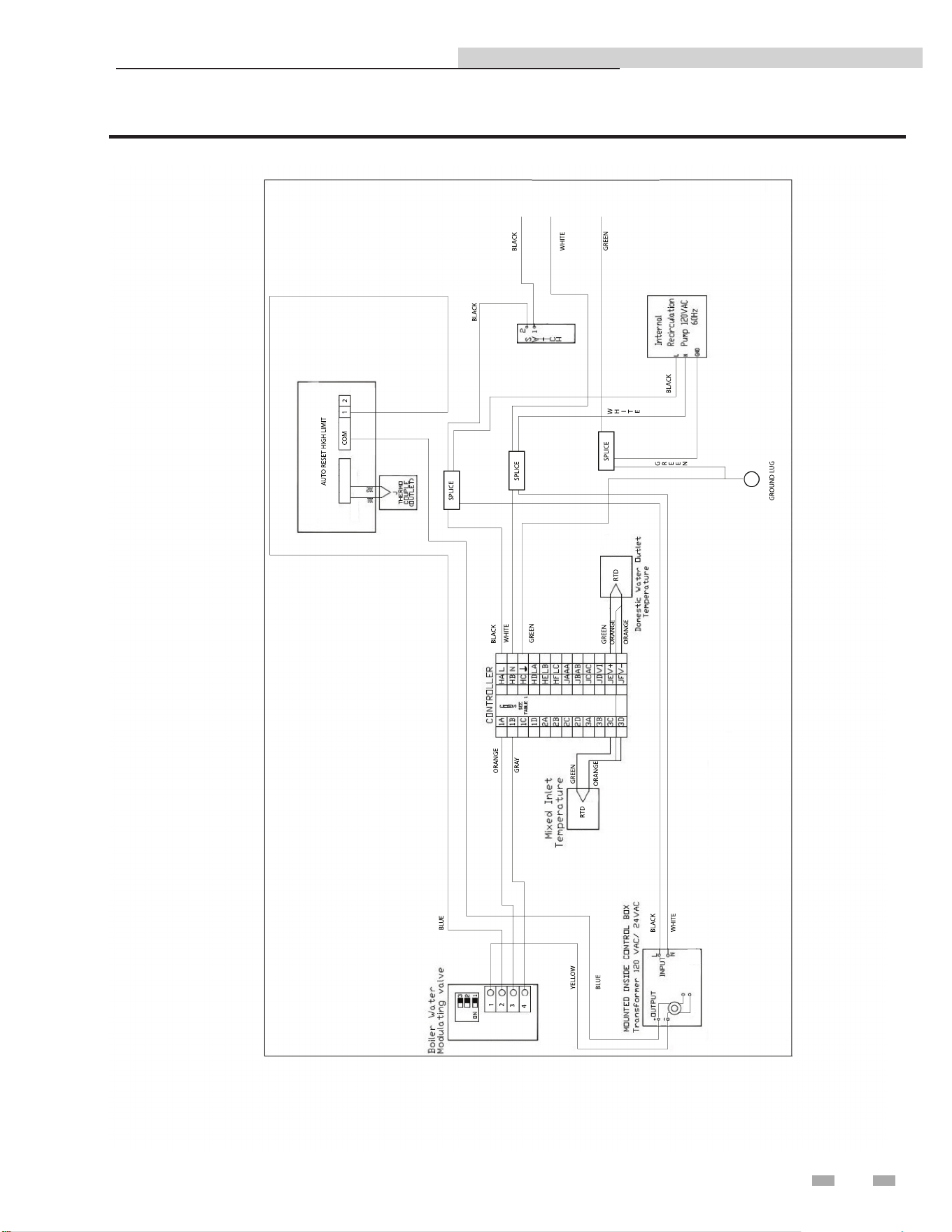
Indirect Plate Water Heater Installation & Service Manual
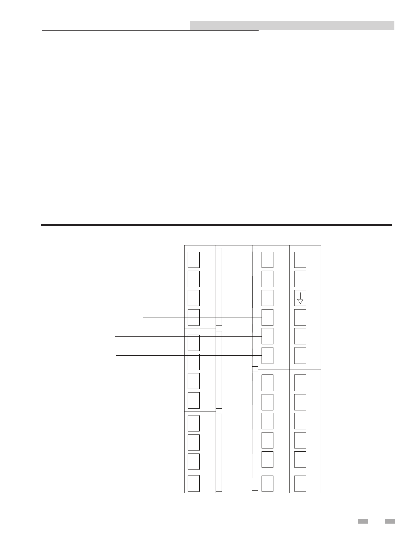
12 Diagrams
Figure 12-1 Wiring Diagram - Electrical Control System Control Box
40
Indirect Plate Water Heater Installation & Service Manual
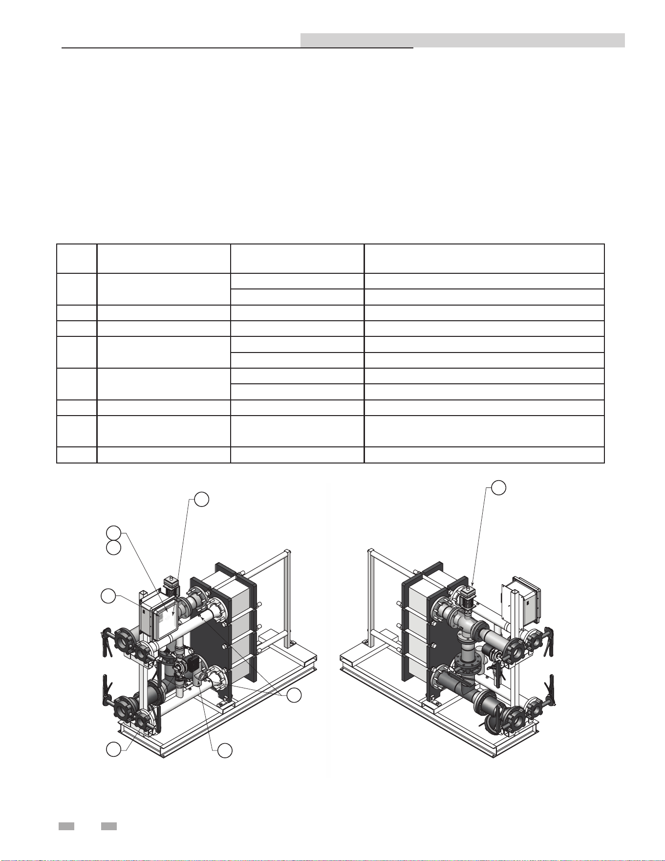
13 Replacement parts list
When ordering replacement parts:
When ordering replacement parts always give the following information:
1. Model, serial, and part number
2. Kit number
3. Parts description
Replacement Parts List
Item
No.
Parts Description Kit # Model
1 Pump
100271293 IPW015DW-070DW
100271294 IPW090DW-120DW
2 Control 100271295 IPW015DW-120DW
3 Sensor 100271296 IPW015DW-120DW
4 T & P Valve
100112873 IPW015DW-050DW
100322498 IPW070DW-120DW
5 Modulating Valve
100271300 IPW015DW-070DW
100271312 IPW090DW-120DW
6 Transformer 100208249 IPW015DW-120DW
7 High Limit
Note: High limit located inside the control
panel.
100402342 IPW015DW-120DW
8 Power Switch 100271316 IPW015DW-120DW
DIR #2000577459
2
8
1
4
3
6
5
7

41
Indirect Plate Water Heater Installation & Service Manual
Notes

42
Indirect Plate Water Heater Installation & Service Manual
Notes

43
Indirect Plate Water Heater Installation & Service Manual
Notes

Revision Notes: Revision A (Process #3000002314_Change
#500002513) initial release.
Revision B (PCP# 3000003781 / CN# 500004056) reflects the addition
of the Modbus chapter on pages 21 through 24.
Revision C (PCP #3000035575 / CN #500024078) reflects updates
made to the manual and the addition of the Series break.
Revision D (PCP #3000048612 / CN #500035892) reflects an update to
Memory Map input and holding register addresses on page 23.
Revision E (PCP #3000054593 / CN #500041076) reflects an update to
the sizing charts on pages 31 through 38.
Revision F (PCP #3000060820 / CN #500046810) reflects the addition
of a dielectric notice on page 8.
Revision G (PCP #3000065254 / CN #500051013) reflects updates to
the table on page 6.
Revision H (PCP #3000070466 / CN #500055929) reflects updates to
figures 4-5 and 6-1, as well as an update to the replacement parts list.
100271422_2000527669_Rev H
02/26