
No. [SI-F-011-DDS26D-01]
Shenzhen Star Instrument Co., Ltd
DDS26D Operation Manual
.

Caution: The user is cautioned that changes or modifications not expressly approved by the
party responsible for compliance could void the user's authority to operate the equipment.
This device complies with Part 15 of the FCC Rules. Operation is subject to the following two
conditions: (1) this device may not cause harmful interference, and (2) this device must accept
any interference received, including interference that may cause undesired operation.
NOTE: This equipment has been tested and found to comply with the limits for a Class B digital
device, pursuant to Part 15 of the FCC Rules. These limits are designed to provide reasonable
protection against harmful interference in a residential installation. This equipment generates,
uses and can radiate radio frequency energy and, if not installed and used in accordance with the
instructions, may cause harmful interference to radio communications. However, there is no
guarantee that interference will not occur in a particular installation.
If this equipment does cause harmful interference to radio or television reception, which can be
determined by turning the equipment off and on, the user is encouraged to try to correct the
interference by one or more of the following measures:
Reorient or relocate the receiving antenna.
Increase the separation between the equipment and receiver.
Connect the equipment into an outlet on a circuit different from that to which the receiver is
connected.
Consult the dealer or an experienced radio/TV technician for help.
FCC Radiation Exposure Statement:
This equipment complies with FCC radiation exposure limits set forth for an uncontrolled
environment. This transmitter must not be co-located or operating in conjunction with any other
antenna or transmitter.
This equipment should be installed and operated with a minimum distance of 20cm between the
radiator and your body.

Change Log
Date
Version
Description of Major Changes
20240607
V1
Adapted from single-phase NH meter according to
requirements
20240615
V2
Updated requirements, corrected parameters
20240618
V2.1
Removed parameters (disconnection reasons) after hardware
adjustment
20240618
V2.2
Synchronized calendar with three-phase meter, adjusted
time-of-use rates
20240619
V2.3
Modified wiring diagram
20240619
V3.0
Corrected errors in prepayment, communication, and load
control
20240619
V3.1
Removed manual disconnection/reconnection operations
20240619
V3.2
Removed descriptions about disconnection reasons and
prepayment
20240619
V3.3
Adjusted structural connection diagrams
20240620
V3.4
Updated based on test feedback
20240628
V3.5
Corrected code 100.8.0 → 19.8.0 in cyclic display

Approval
Signature
Date
Prepared
Verified
Reviewed
Approved
Special Statement
Continuous improvement is the policy of Shenzhen Star Instrument Co., Ltd. We reserve the right
to modify specifications without prior notice. Total or partial reproduction is prohibited without
written authorization.
Preface
General Safety Requirements
This meter facilitates verification, installation, and operation. To prevent risks:
1. Read this manual thoroughly before any operation.
2. Only qualified personnel authorized by our company may perform maintenance.
3. Improper use or use outside specifications voids all manufacturer responsibility.
Safety Information
Signals according to risk level:
Warning! Indicates risk of serious injury or irreparable damage.
Caution! Indicates possible equipment damage, data loss, or minor injuries.
Safety Rules
Respect maximum voltage/current ratings.
Verify measured load capacity.
Safe installation and connection:
Use conductors with adequate cross-section.
No contact with bare cables.
Prohibited use in explosive environments.
Keep equipment surface clean and sealed.
Never immerse the meter in liquids or chemical agents.
Displayed data are illustrative examples.
Always disconnect power during installation/maintenance.
Comply with local regulations: only certified technicians may handle the equipment.
Discard meters with physical damage or impact.
Note: All specifications are subject to change without prior notice.

Corporate Profile of Shenzhen Star Instrument Co., Ltd.
Specialized in R&D, manufacturing, and marketing of energy metering systems, we have:
Certified engineering team.
ISO9001 management system certified by BSI (UK).
Production processes with cutting-edge technology.
For over a decade, we have provided reliable solutions for global customers based on three
pillars:
-Technology as the driver.
-Quality as the foundation.
-Constant innovation.
Committed to "Technical Excellence, Customer Focus," we drive the evolution of the electrical
sector.
Product Line
Single-phase/three-phase meters.
Prepayment systems + commercial management.
Multi-rate meters.
Multifunction meters.
PLC systems (carrier meters + remote collection).
Metrological verification equipment.
Contact STAR
Tel: +86-755-86358888
Fax: +86-755-86359999
Address: 23rd Floor, West Tower, Coastal Building, Haide 3rd Ave., Nanshan, Shenzhen 518054,
China
E-mail: [email protected]om
Web: www.szstar.com

1 Introduction to the Energy Meter....................................................................................... 11
1.1 Technical Summary ...................................................................................................... 11
Mechanical Configuration .........................................................................................11
Main Application..........................................................................................................11
Key Features.................................................................................................................. 12
Compliant Standards.................................................................................................. 12
1.2 Technical Parameters................................................................................................... 13
Electrical Performance ................................................................................................14
Electromagnetic Compatibility ................................................................................ 14
Insulation Performance..............................................................................................15
Usage Environment .....................................................................................................15
Communication Interface..........................................................................................16
1.3 Operating Principle ...................................................................................................... 16
2 Structural Description ............................................................................................................. 17
2.1 Structural Dimensions of the Energy Meter ..........................................................17
2.2 Wiring Diagram............................................................................................................. 19
2.3 Meter Protection Level ................................................................................................ 19
2.4 Flame Resistance Performance................................................................................. 19
3 Measurement Principle ...........................................................................................................20
4 Energy..........................................................................................................................................20
4.1 Basic Energy ....................................................................................................................21
4.2 Incremental Energy ...................................................................................................... 22

Monthly Incremental Energy....................................................................................22
Curve Cycle Incremental Energy............................................................................. 25
5 Demand .......................................................................................................................................26
5.1 Current Demand............................................................................................................26
5.2 Maximum Demand .......................................................................................................27
5.3 Demand Storage and Reset....................................................................................... 29
6 Instantaneous Values.............................................................................................................. 29
6.1 Basic Values .................................................................................................................... 29
6.2 Other Instantaneous Quantities ............................................................................... 30
7 Clock .............................................................................................................................................30
7.1 Clock Accuracy...............................................................................................................30
7.2 Functions ......................................................................................................................... 31
8 Communications...................................................................................................................... 31
8.1 Local Communication ..................................................................................................31
8.2 RS485 Communication ................................................................................................31
8.3 Remote Communication .............................................................................................32
9 HMI ...............................................................................................................................................32
9.1 Display Buttons..............................................................................................................32
Display Buttons............................................................................................................ 32
9.2 Backlight .......................................................................................................................... 33
9.3 LCD Display .....................................................................................................................33
Explanation of LCD Display Content ...................................................................... 33

Automatic Rotation Display ......................................................................................35
Button Display .............................................................................................................. 36
Power-off Display.........................................................................................................38
Display Characteristics ............................................................................................... 38
9.4 LED Indicators................................................................................................................ 39
Pulse Indicator Lights ................................................................................................. 39
Alarm Indicator Light..................................................................................................39
Credit/Power Indicator Light .................................................................................... 40
10 Load Management................................................................................................................ 40
10.1 Limiter ............................................................................................................................ 40
10.2 Monitor ..........................................................................................................................40
10.3 Load Control ................................................................................................................ 41
11 Relay Control ...........................................................................................................................41
11.1 Common Disconnection Reasons..........................................................................42
12 Settlement ................................................................................................................................42
12.1 Monthly Settlement ...................................................................................................42
12.2 Daily Settlement ......................................................................................................... 43
13 Load Curve ...............................................................................................................................43
13.1 Load Curve 1................................................................................................................44
13.2 Load Curve 2................................................................................................................45
14 Events........................................................................................................................................ 45
14.1 Event Grouping ........................................................................................................... 46

14.2 Event Detection ...........................................................................................................46
14.3 Event Reporting .......................................................................................................... 47
14.4 Event Configuration ...................................................................................................47
15 PUSH ..........................................................................................................................................47
15.1 Data Reporting ............................................................................................................47
16 Time-of-Use Tariffs ................................................................................................................ 48
17 Payment Mode ....................................................................................................................... 49
17.1 Post-payment Mode.................................................................................................. 49
18 Common Fault Handling ......................................................................................................49
1 Introduction to the Energy Meter
1.1 Technical Summary
Mechanical Configuration
Main Application
The single-phase post-payment meter DDS26D exchanges data through digital
means. Key functionalities:
✓ Active energy and demand measurement.
✓ Post-payment mode.
✓ Removable interfaces for PLC/4G/RF modules.
✓ Remote reading and parameter configuration.

Key Features
▸ Combined energy: Sum of active + reactive energy.
▸ Load control: Automatic disconnection/reconnection due to overload.
▸ Event recording.
▸ LCD display: Shows energy, demand, rates, alerts.
▸ Touch buttons: Intuitive navigation.
▸ Dual communication:
o PLC/4G/RF for remote reading.
o Recharge management/control via Internet.
▸ Post-payment system:
o Centralized reading.
o Billing in master system.
Compliant Standards
IEC62052-11 Electricity metering equipment(AC)-General
requirements,tests and test conditions- Part11:Metering equipment
IEC62053-21 Electricity metering equipment(a.c.)-Particular
requirements-Part21:Static meters for active energy(classes 1 and 2)

IEC62056-21 Electricity metering - Data exchange for meter reading,
tariff and load control -Part 21: Direct local data exchange
IEC62056-46 Electricity metering --Data exchange for meter
reading,tariff and load control --Part 46:Data link layer using HDLC
protocol
IEC62056-53 Electricity metering --Data exchange for meter
reading,tariff and load control --Part 53:COSEM application layer
IEC62056-61 Electricity metering --Data exchange for meter reading,
tariff and load control --Part 61:Object identification system
IEC62056-62 Electricity metering --Data exchange for meter reading,
tariff and load control --Part 62:Interface classes
1.2 Technical Parameters
Connection
LNNL
Rated Voltage
220/380V
Rated Current (Ib)
5A
Maximum Current (Imax)
80A
Starting Current
Active: 0.4%Ib
Reactive: 0.5%Ib

Rated Frequency
50Hz
Accuracy Class
Active: Class 1
Reactive: Class 2
Pulse Constant
1000 imp/kWh
1000 imp/kvarh
Electrical Performance
Operating Voltage Range
0.7Un - 1.2Un
Starting Current
0.004Ib
Operating Frequency Range
50Hz ±5%
Power Consumption
Voltage line ≤1.5W, 10VA
Current line ≤2.5VA
Electromagnetic Compatibility
No.
Project Name
IEC62053-21
Requirements
1
Electrostatic Discharge Immunity
Contact discharge: 8kV
Air discharge: 15kV
2
High-Frequency Electromagnetic Field
80MHz-2GHz 30V/m

Immunity
3
Fast Transient Burst Immunity
4kV/2.5kHz
4
Radio Interference Test
Class B equipment CISPR
22
5
RF Field Induced Conducted Disturbance
Immunity
150kHz–80MHz 10V/m
6
Surge Immunity
4kV
Insulation Performance
No.
Project Name
IEC62053-21 Requirements
1
Impulse Voltage
Class II insulation: 6kV
2
AC Voltage
Current line to ground (Class II insulation): 4kV
Between auxiliary terminals: 2kV
Usage Environment
No.
Project Name
IEC62053-21 Requirements
1
Temperature
Operating temperature range: -25℃ to 60℃
Limit operating temperature range: -40℃ to 70℃
Storage and transportation temperature range: -40℃ to

80℃
2
Humidity
Annual average: ≤75%
30 days per year: ≤95%
Rest of the time: ≤85%
Communication Interface
Type
Description
Baudrate
Unmodulated
Infrared
Bidirectional serial communication
interface
9600 bps 8N1
RS485
Bidirectional serial communication
interface
9600bps 8N1
RF Module
Bidirectional serial communication
interface
9600bps 8N1
1.3 Operating Principle
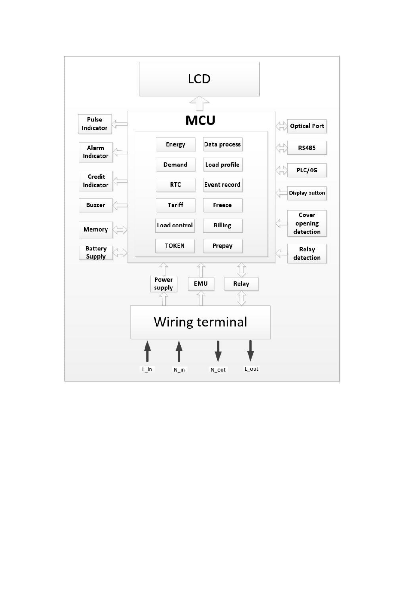
Block diagram of the principle.
2 Structural Description
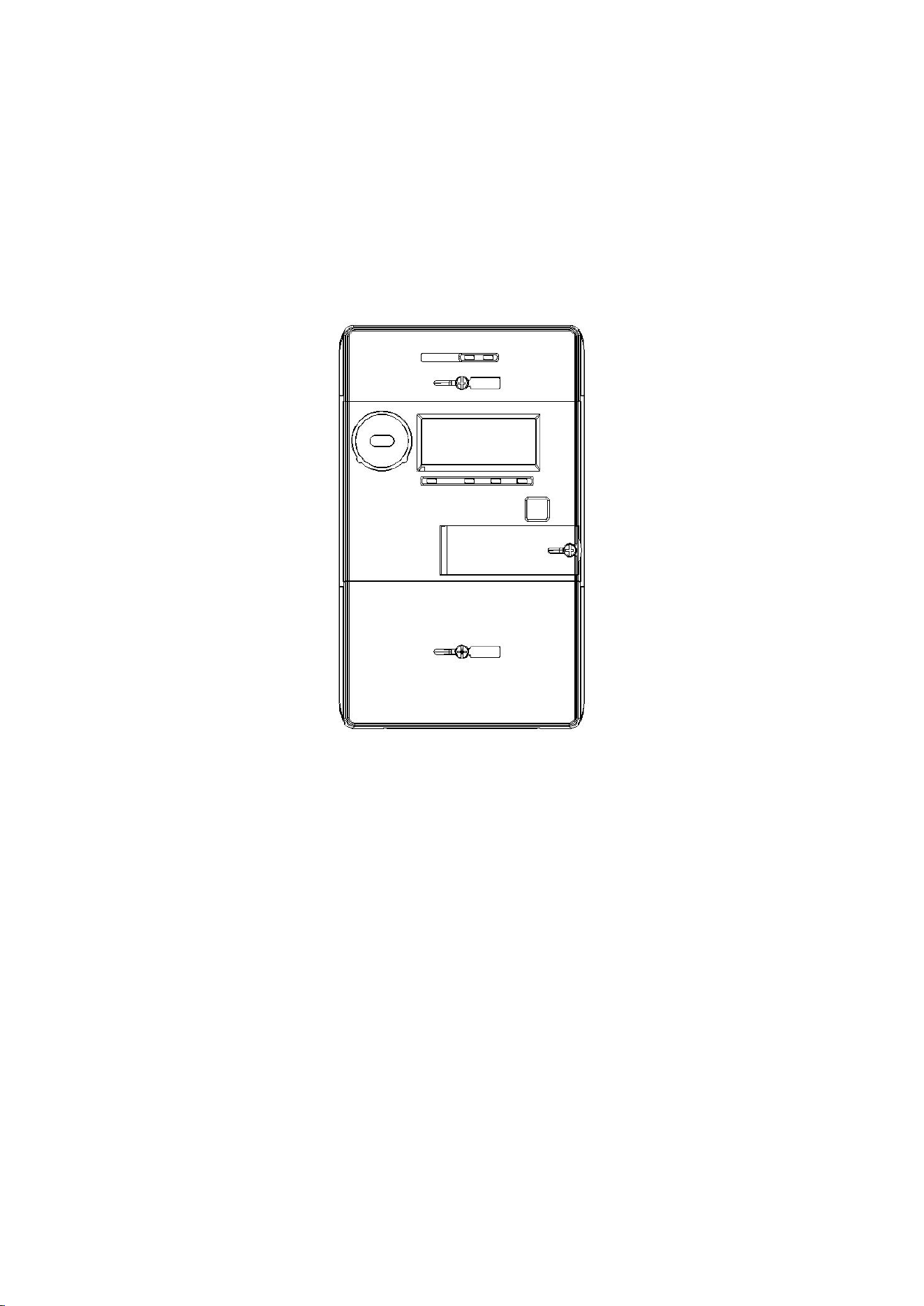
2.1 Structural Dimensions of the Energy Meter
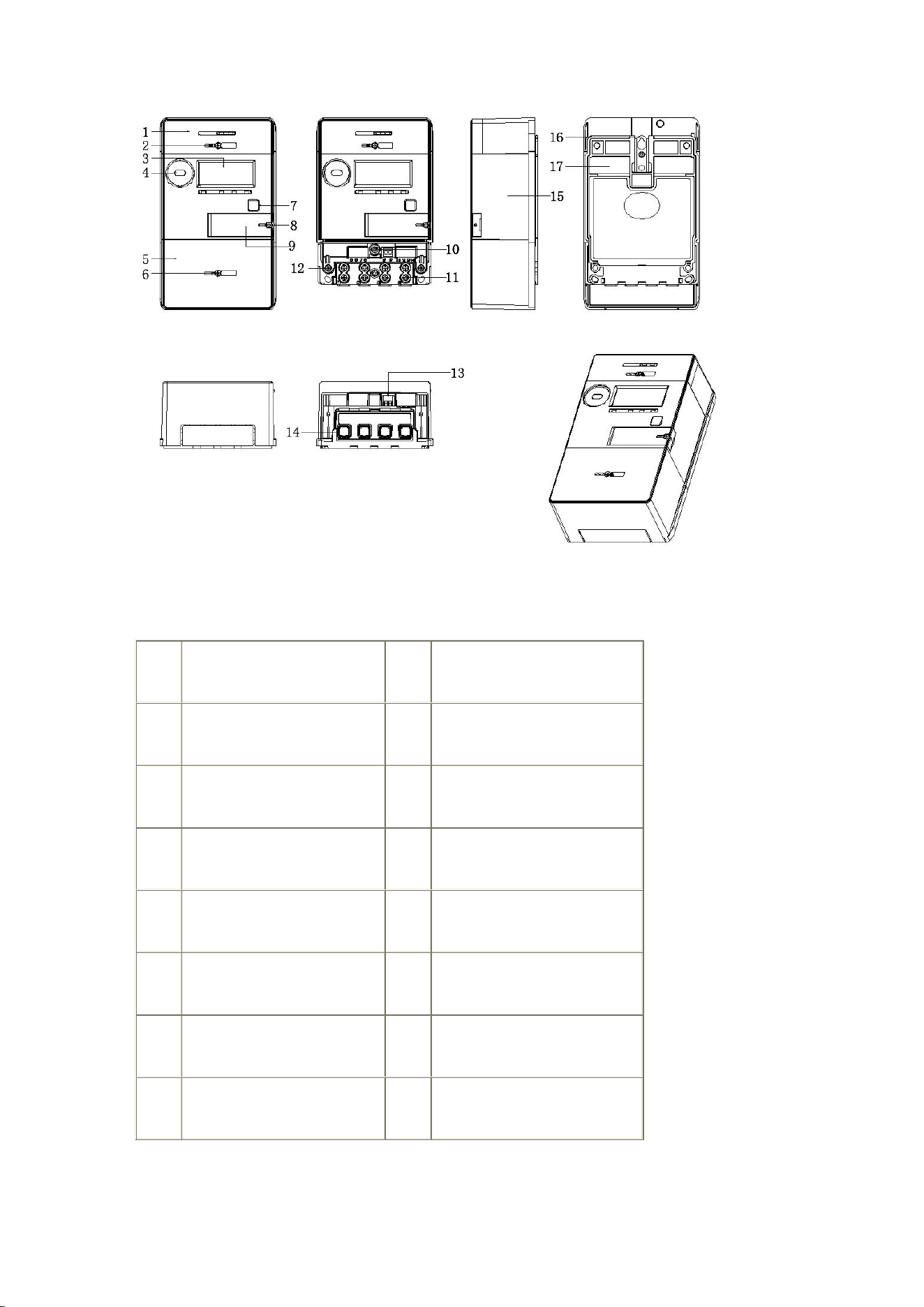
Ref.
Component
Ref.
Component
01
Module Case
02
Module Case Lead Seal
03
LCD Viewing Window
04
Optical Port
05
Terminal Cover
06
Terminal Cover Lead Seal
07
Display Buttons
08
Battery Cover Lead Seal
09
Battery Cover
10
Cover Opening Detection
11
Cable Clamping Screws
12
Top Cover Lead Seal
13
RS485 Output Terminals
14
Current Terminals
15
Top Cover
16
Mounting Hook
17
Bottom Housing
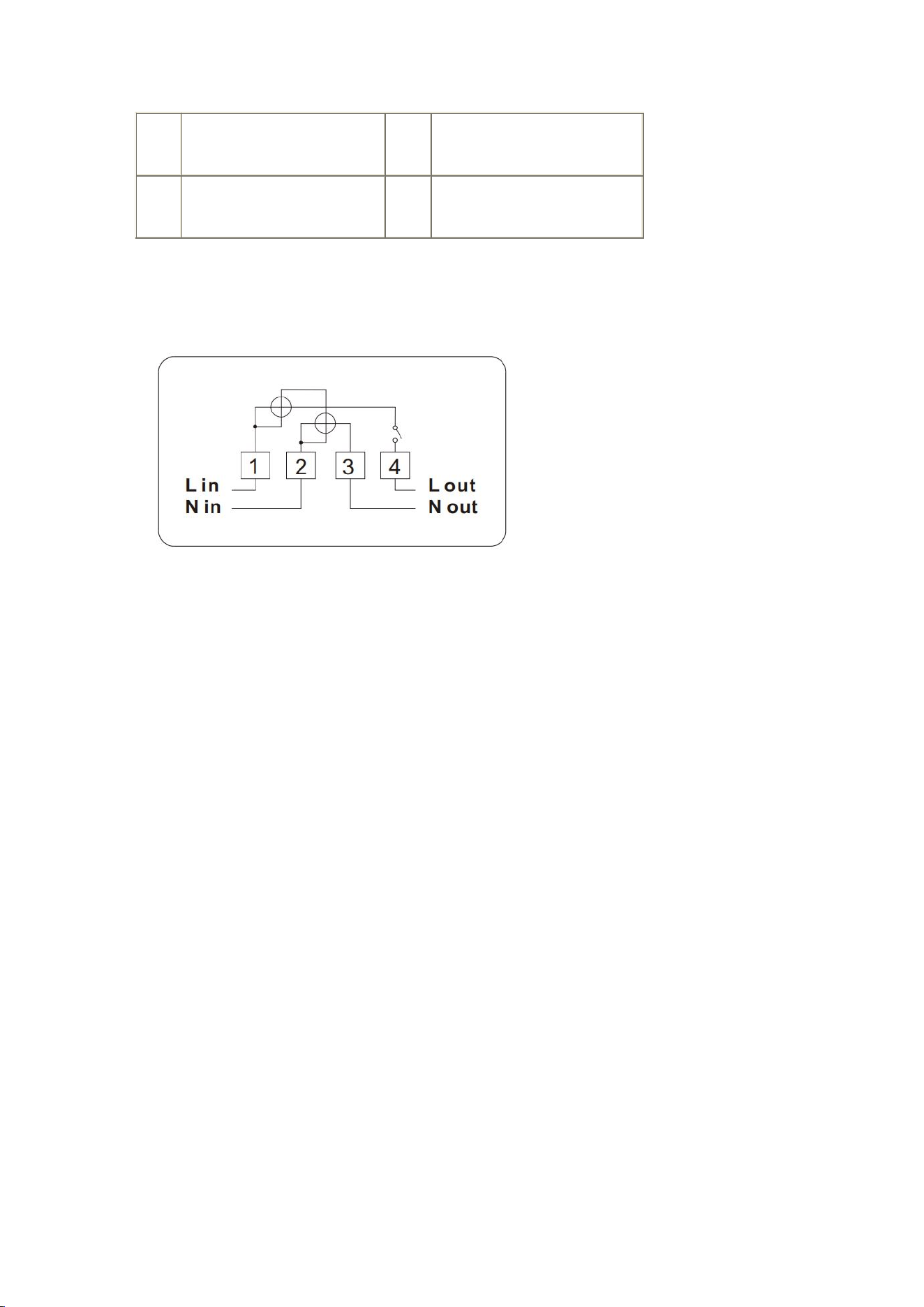
2.2 Wiring Diagram
Terminal description:
1: Phase line L in
4: Phase line L out
2: Neutral line N in
3: Neutral line N out
2.3 Meter Protection Level
According to standard IEC60529 -- 4, the test results of the prepayment meter from
Shenzhen Star Instrument Co., Ltd. are: IP54.
2.4 Flame Resistance Performance
Flame resistance class: V0 (the housing is entirely made of flame-retardant and
heat-resistant material).
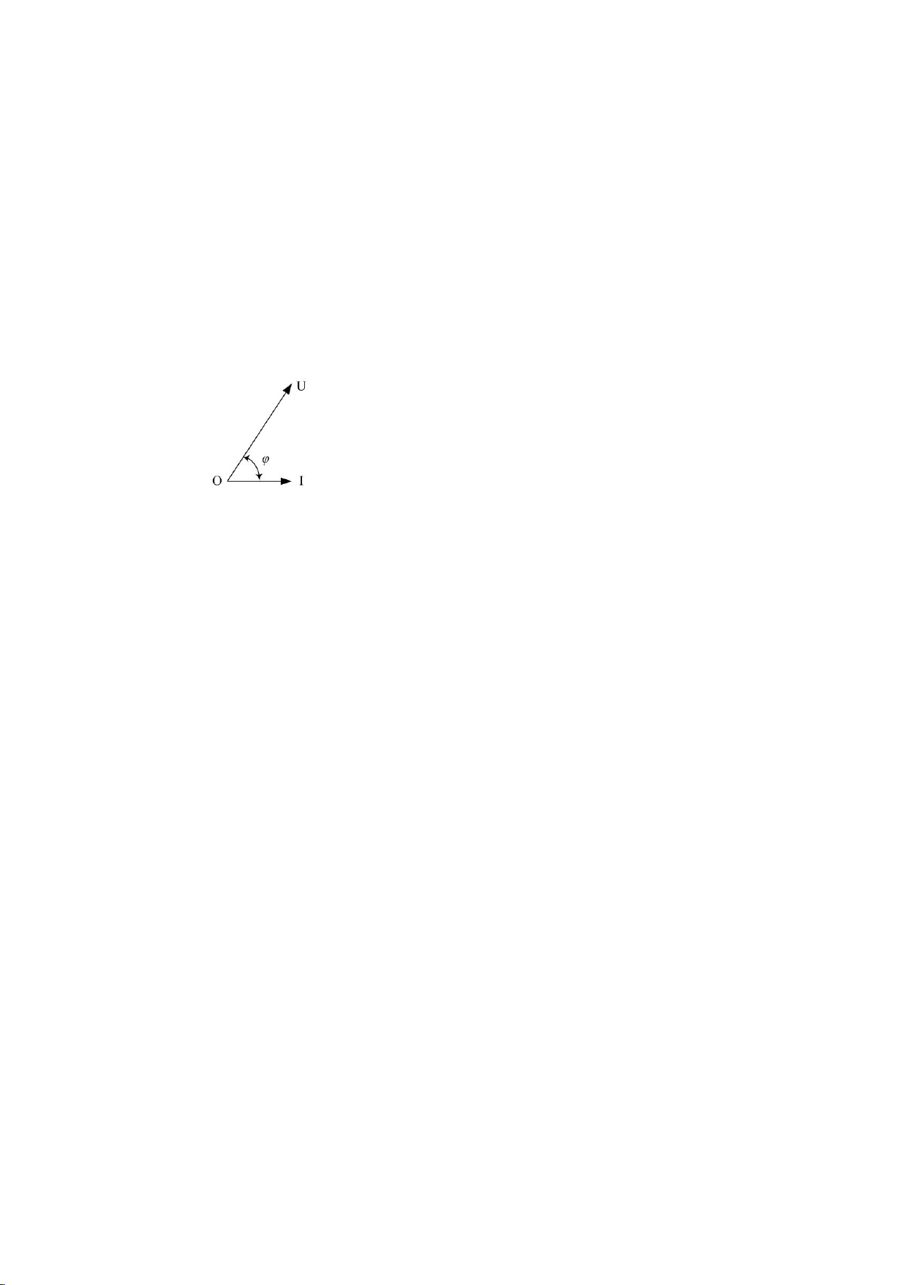
3 Measurement Principle
Vector diagram of energy meter measurement.
● Active Power
P = UI cos φ
● Active Energy:
E
P
= ∫P d t = ∫UI cos φ d t
● Energy direction defined by the meter:
Forward active energy = Active energy of quadrant I + quadrant IV
Reverse active energy = Active energy of quadrant II + quadrant III
Combined active energy = Sum of all four quadrants
4 Energy
The meter supports multiple types of energy measurement:

4.1 Basic Energy
Category
Measurement Object
IC
Identifier
Unit
Active Energy
Total and per tariff forward active
energy
3
1-0:1.8.T.255
(0, Wh)
Total and per tariff reverse active
energy
1-0:2.8.T.255
Total combined active energy per
tariff
1-0:15.8.T.255
Total net active energy per tariff
1-0:16.8.T.255
Reactive
Energy
Total and per tariff forward reactive
energy
1-0:3.8.T.255
(0,
varh)
Total and per tariff reverse reactive
energy
1-0:4.8.T.255
Total quadrant 1 reactive energy
per tariff
1-0:5.8.T.255
Total quadrant 2 reactive energy
per tariff
1-0:6.8.T.255

Total quadrant 3 reactive energy
per tariff
1-0:7.8.T.255
Total quadrant 4 reactive energy
per tariff
1-0:8.8.T.255
Combined reactive energy
1-0:17.8.T.255
Net reactive energy
1-0:18.8.T.255
Total inductive reactive energy per
tariff
1-0:100.8.T.255
Total capacitive reactive energy per
tariff
1-0:104.8.T.255
Apparent
Energy
Total forward apparent energy per
tariff
1-0:9.8.T.255
(0,
VAh)
Total reverse apparent energy per
tariff
1-0:10.8.T.255
Note: "T" identifies the tariff: T=0 for total, T=1~N for specific tariffs.
4.2 Incremental Energy
Monthly Incremental Energy

Incremental monthly energy measurement objects supported by the
energy meter, and their corresponding units/dimensions are shown
in the following table:
Energy
Category
Energy Object
IC
Object
Identifier
Unit/Dimension
Active
Energy
Total and per tariff monthly
incremental forward active
energy
3
1-0:1.9.T.255
(0, Wh)
Total and per tariff monthly
incremental reverse active
energy
1-0:2.9.T.255
Total and per tariff monthly
incremental combined active
energy
1-0:15.9.T.255
Total and per tariff monthly
incremental net active
energy
1-0:16.9.T.255
Reactive
Energy
Total and per tariff monthly
incremental forward reactive
energy
1-0:3.9.T.255
(0, varh)

Total and per tariff monthly
incremental reverse reactive
energy
1-0:4.9.T.255
Total and per tariff monthly
incremental quadrant 1
reactive energy
1-0:5.9.T.255
Total and per tariff monthly
incremental quadrant 2
reactive energy
1-0:6.9.T.255
Total and per tariff monthly
incremental quadrant 3
reactive energy
1-0:7.9.T.255
Total and per tariff monthly
incremental quadrant 4
reactive energy
1-0:8.9.T.255
Apparent
Energy
Total and per tariff monthly
incremental forward
apparent energy
1-0:9.9.T.255
(0, VAh)
Total and per tariff monthly
incremental reverse
1-0:10.9.T.255

apparent energy
Note:
In the object identifiers in the table above, T is the tariff number identifier:
T = 0: Indicates total energy.
T = 1~N: Indicates energy per tariff (where N is the total number of tariffs
supported). For more details on the specific number of tariffs supported, refer
to the chapter "Time-of-Use Tariffs".
Curve Cycle Incremental Energy
Energy
Category
Active Energy
IC
Object
Identifier
Unit/Dimension
Active Energy
Cycle incremental forward active
energy
3
1-0:1.29.0.255
(1, Wh)
Cycle incremental reverse active
energy
1-0:2.29.0.255
Cycle incremental combined active
energy
1-0:15.29.0.255
Cycle incremental net active energy
1-0:16.29.0.255
Reactive
Energy
Cycle incremental forward reactive
energy
1-0:3.29.0.255
(1, varh)
Cycle incremental reverse reactive
energy
1-0:4.29.0.255
Cycle incremental quadrant 1
1-0:5.29.0.255

The meter supports the following curve cycle incremental energy
measurement objects, with their corresponding units:
5 Demand
The meter supports demand calculation, with customizable period and number of
cycles. The ranges and default values are:
Object
Configurable Range
Default Value
Demand Period
1~60 min
15 min
Number of Demand Periods
12
6
5.1 Current Demand
The current demand objects supported by the meter, along with
their units, are:
Demand
Category
Demand Object
IC
Object
Identifier
Unit/Dimension
reactive energy
Cycle incremental quadrant 2
reactive energy
1-0:6.29.0.255
Cycle incremental quadrant 3
reactive energy
1-0:7.29.0.255
Cycle incremental quadrant 4
reactive energy
1-0:8.29.0.255
Apparent
Energy
Cycle incremental forward apparent
energy
1-0:9.29.0.255
(1, VAh)
Cycle incremental reverse apparent
energy
1-0:10.29.0.255

Active Demand
Current forward active demand
(total and per tariff)
5
1-0:1.4.T.255
(0, W)
Current reverse active demand (total
and per tariff)
1-0:2.4.T.255
Reactive
Demand
Current forward reactive demand
(total and per tariff)
1-0:3.4.T.255
(0, var)
Current reverse reactive demand
(total and per tariff)
1-0:4.4.T.255
Current quadrant 1 reactive demand
(total and per tariff)
1-0:5.4.T.255
Current quadrant 2 reactive demand
(total and per tariff)
1-0:6.4.T.255
Current quadrant 3 reactive demand
(total and per tariff)
1-0:7.4.T.255
Current quadrant 4 reactive demand
(total and per tariff)
1-0:8.4.T.255
Apparent
Demand
Current forward apparent demand
(total and per tariff)
1-0:9.4.T.255
(0, VA)
Current reverse apparent demand
(total and per tariff)
1-0:10.4.T.255
Combined
Demand
Current combined active demand
1-0:15.4.T.255
Note:
In the identifiers in the table, "T" represents the tariff code:
T = 0: Total demand.
T = 1~N: Demand per specific tariff (refer to the chapter "Time-of-Use Tariffs"
for the number of tariffs supported, N).
5.2 Maximum Demand

The meter supports the following maximum demand objects, with
their corresponding units:
Demand
Category
Demand Object
IC
Object
Identifier
Unit/Dimension
Active Demand
Maximum forward active demand
(total and per tariff)
4
1-0:1.6.T.255
(0, W)
Maximum reverse active demand
(total and per tariff)
1-0:2.6.T.255
Reactive
Demand
Maximum forward reactive demand
(total and per tariff)
1-0:3.6.T.255
(0, var)
Maximum reverse reactive demand
(total and per tariff)
1-0:4.6.T.255
Maximum quadrant 1 reactive
demand (total and per tariff)
1-0:5.6.T.255
Maximum quadrant 2 reactive
demand (total and per tariff)
1-0:6.6.T.255
Maximum quadrant 3 reactive
demand (total and per tariff)
1-0:7.6.T.255
Maximum quadrant 4 reactive
demand (total and per tariff)
1-0:8.6.T.255
Apparent
Demand
Maximum forward apparent demand
(total and per tariff)
1-0:9.6.T.255
(0, VA)
Maximum reverse apparent demand
(total and per tariff)
1-0:10.6.T.255
Combined
Demand
Maximum combined active demand
1-0:15.6.T.255
Note:
In the identifiers in the table, "T" represents the tariff code:
T = 0: Total maximum demand.

T = 1~N: Maximum demand per specific tariff (refer to the chapter
"Time-of-Use Tariffs" for the number of tariffs supported, N).
5.3 Demand Storage and Reset
When the meter reaches the monthly storage time (monthly settlement), the
monthly maximum demand is automatically stored and then reset to start a new
calculation. For details on the monthly settlement mechanism, refer to the chapter
"Settlement".
(When the energy meter reaches the configured monthly transfer time (monthly
settlement), the monthly maximum demand is automatically transferred and then
cleared to restart calculation. For functions related to monthly settlement, refer to
the chapter "Settlement".)
The meter supports button-activated settlement.
6 Instantaneous Values
The meter supports real-time measurement of instantaneous values.
6.1 Basic Values
Category
Object
IC
Object Identifier
Unit/Dimension
Voltage
Phase A
3
1-0:32.7.0.255
(-1, V)
Current
Phase A
1-0:31.7.0.255
(-2, A)
Neutral
1-0:91.7.0.255

Active Power
Forward (Phase A)
1-0:21.7.0.255
(0, W)
Reverse (Phase A)
1-0:22.7.0.255
Combined
1-0:15.7.0.255
Reactive Power
Forward
1-0:3.7.0.255
(0, var)
Reverse
1-0:4.7.0.255
Quadrant 1
1-0:5.7.0.255
Quadrant 2
1-0:6.7.0.255
Quadrant 3
1-0:7.7.0.255
Quadrant 4
1-0:8.7.0.255
Apparent Power
Forward
1-0:9.7.0.255
(0, VA)
Reverse
1-0:10.7.0.255
Power Factor
Forward
1-0:13.7.0.255
(-3, NULL)
Phase A
1-0:33.7.0.255
Reverse
1-0:84.7.0.255
Grid Frequency
Grid frequency
1-0:14.7.0.255
(-2, Hz)
6.2 Other Instantaneous Quantities
The related objects and their units are shown in the following table:
Category
Object
IC
Object Identifier
Unit/Dimension
Battery Voltage
External battery voltage
3
0-0:96.6.3.255
(-3, V)
7 Clock
7.1 Clock Accuracy
The meter's clock complies with the requirements of standard IEC62054-21:

At reference temperature (23°C): Accuracy ≤ ±0.5 s/day.
In the range of -25°C to +60°C: Accuracy ≤ ±1 s/day.
When the meter loses power, the backup battery maintains clock accuracy.
7.2 Functions
Calendar, timer, and automatic leap year adjustment.
Remote clock adjustment via master software or master station.
Broadcast synchronization.
Supported date range: 2012-01-01 to 2099-12-31.
Support for time zones.
8 Communications
8.1 Local Communication
The meter includes an optical communication port, compatible with the physical
standard IEC62056-21 and the DLMS/COSEM protocol (HDLC mode).
It allows reading energy data, demand, events, and settlements, as well as
configuring parameters via master software.
8.2 RS485 Communication
RS485 port compatible with HDLC protocol, used for concentrator
networks and remote reading.

8.3 Remote Communication
Supports removable communication modules (DLMS/COSEM protocol, Wrapper
and TCP/UDP).
Two AMI connection modes:
4G: Direct connection to master station.
RF: Connection via DCU.
Functions:
Remote data reading.
Meter programming.
Mode change.
Prepayment recharge.
Relay control.
All communications are encrypted.
9 HMI
9.1 Display Buttons
Display Buttons
Automatic mode: Short press to enter manual mode.
Manual mode: Short press to navigate pages.
Inactivity time: 10 seconds (adjustable between 1-60 s) to return to automatic
mode.
9.2 Backlight
Activation: When any button is pressed (lasts 20 s by default, adjustable).
Configuration:
0: Disables backlight.
Other values: Custom off time.
9.3 LCD Display
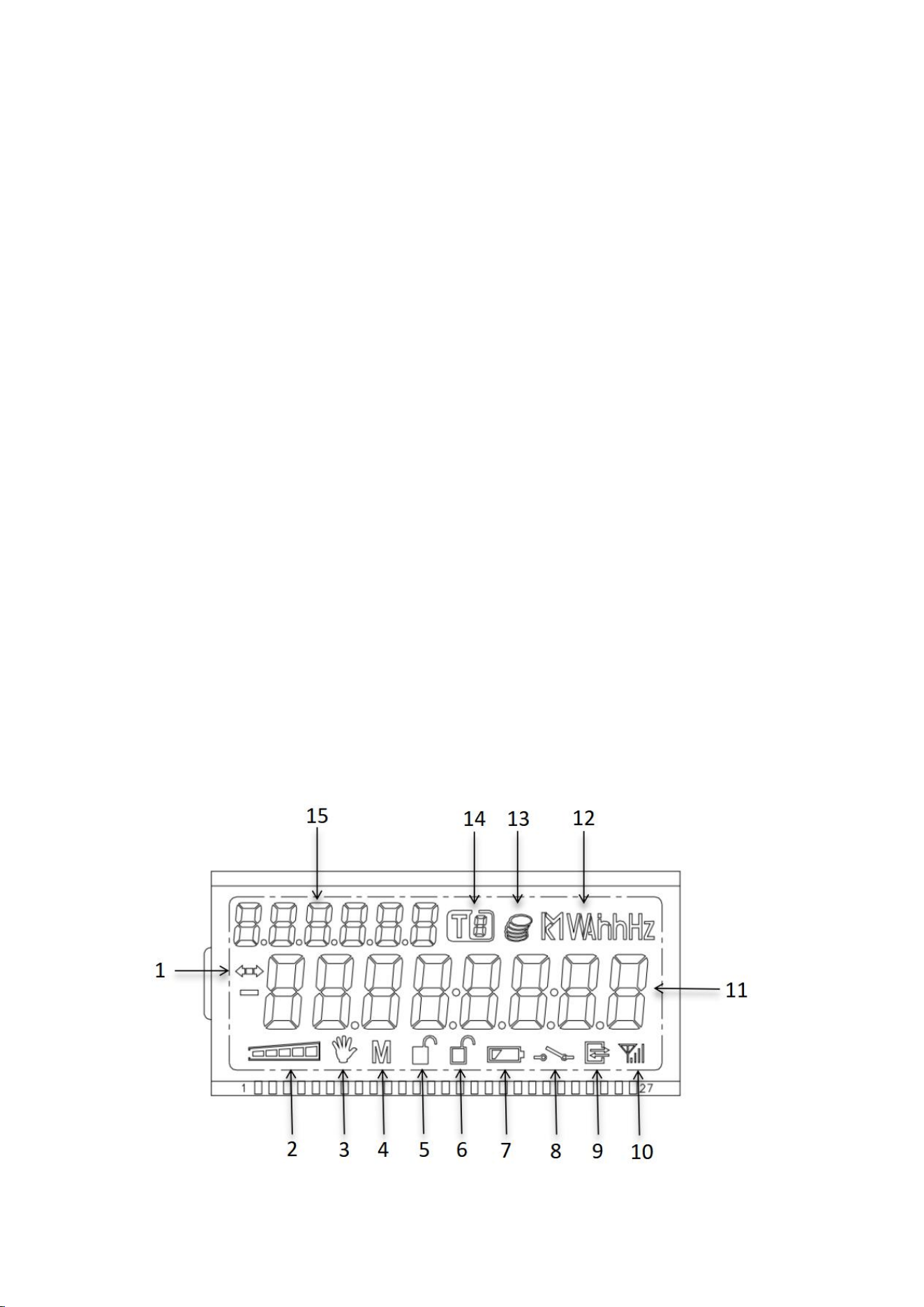
Explanation of LCD Display Content

Ref.
Indicator Name
Description
1
Consumption Direction
Indicator
Right arrow: forward consumption. Left arrow: reverse
consumption. Disappears when no consumption.
2
Balance Level Bar
Shows real-time balance level.
3
Tamper Indicator
Tamper history: activates in case of bypass and persists after its
end.
4
Reserved
Reserved
5
Cover Open Indicator
Activates when the cover is opened and disappears when
closed.
6
Upper Cover Open
Indicator
Activates when the upper cover is opened and disappears
when closed.
7
Battery Indicator
Flashes if voltage <3.0V; disappears if ≥3.0V.
8
Relay Status
Shows "disconnected" when the relay is open; not shown in
closed state.
9
Communication
Indicator
Activates during communications.
10
4G Module Status
Shows signal strength and GPRS connection status.
11
Data Area
Displays data (e.g., date, serial number). Long data (>8
characters) are split into screens.
12
Units
Unit symbols (Wh, varh, V, A, etc.).
13
Currency Symbol
Only in prepayment mode (disabled by default).
14
Current Tariff
Indicates the active tariff code.
15
Data Identifier
Abbreviated object codes (e.g., "15.8.0").
4G Signal Indicator
Symbol
State
Steady Light
Blinking
No display
Module not detected.
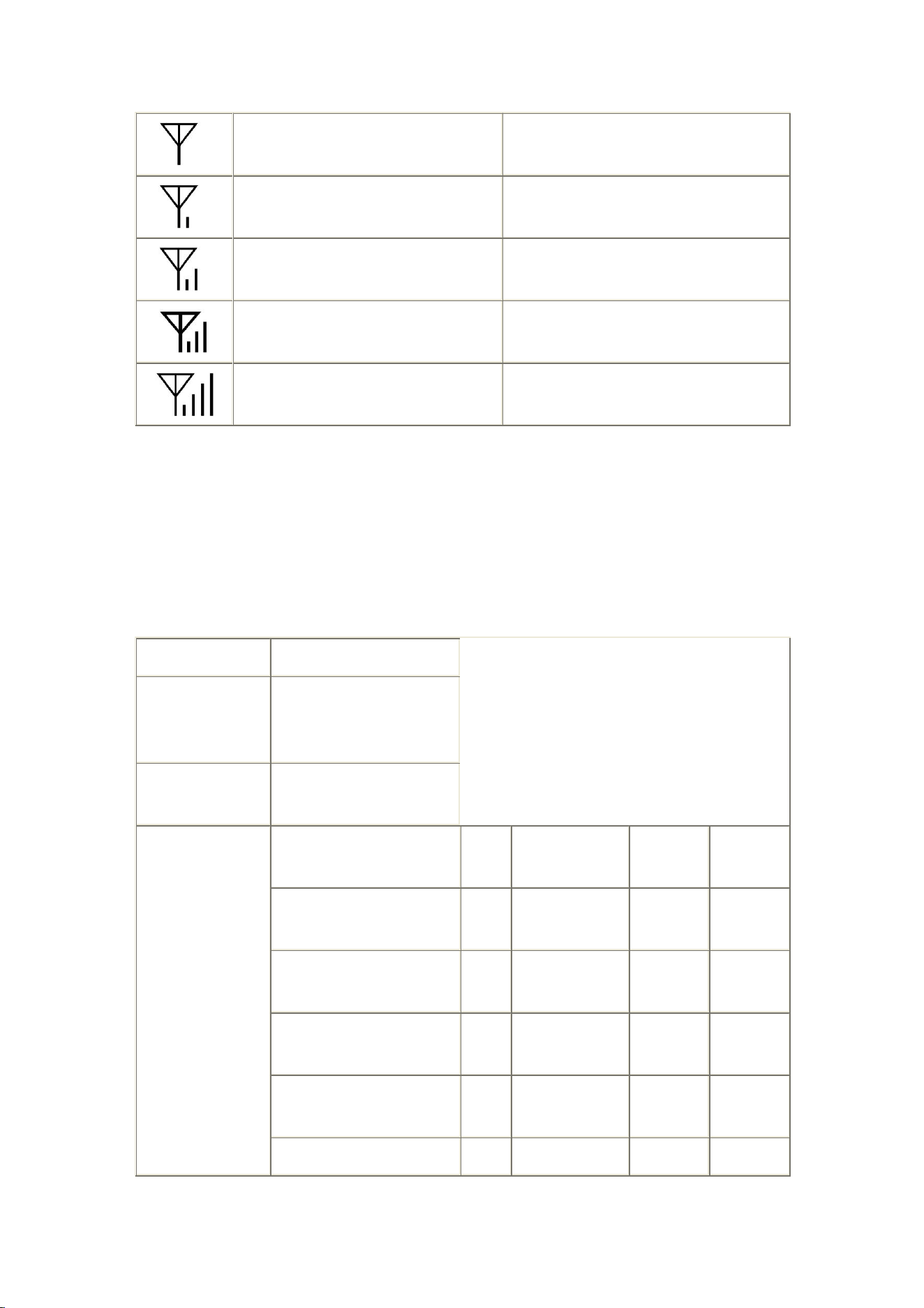
No signal (<-111 dBm)
SIM error
Signal (-111 to -108 dBm): Connection
established
Signal (-111 to -108 dBm): Connection
not established
Signal: -107 to -102 dBm, Connection
established
Signal: -107 to -102 dBm, Connection not
established
Signal: -101 to -92 dBm, Connection
established
Signal: -101 to -92 dBm, Connection not
established
Signal: ≥-91 dBm, Connection
established
Signal: ≥-91 dBm, Connection not
established
Automatic Rotation Display
When powered on with no operation, the meter enters automatic rotation display
mode.
Parameter
Content
Automatic
Rotation Interval
1~60 seconds
configurable, default 8
seconds
Configurable
Display Objects
Maximum 120
Default Display
List
Data Item
Class
OBIS
Attribute
Display
Code
Total Combined Active
Energy
3
1-0:15.8.0.255
2
15.8.0
Total Combined Active
Energy T1
3
1-0:15.8.1.255
2
15.8.1
Total Combined Active
Energy T2
3
1-0:15.8.2.255
2
15.8.2
Total Combined Active
Energy T3
3
1-0:15.8.3.255
2
15.8.3
Total Combined Active
3
1-0:15.8.4.255
2
15.8.4

Energy T4
Total Inductive Reactive
Energy
3
1-0:100.8.0.255
2
100.8.0
L1 Phase Voltage
3
1-0:32.7.0.255
2
32.7.0
L1 Phase Current
3
1-0:31.7.0.255
2
31.7.0
Total Combined Forward
Active Maximum Demand
3
1-0:15.6.0.255
2
15.6.0
Total Combined Forward
Active Maximum Demand
T1
3
1-0:15.6.1.255
2
15.6.1
Total Combined Forward
Active Maximum Demand
T2
3
1-0:15.6.2.255
2
15.6.2
Total Combined Forward
Active Maximum Demand
T3
3
1-0:15.6.3.255
2
15.6.3
Total Combined Forward
Active Maximum Demand
T4
3
1-0:15.6.4.255
2
15.6.4
Total Combined Reactive
Energy
3
1-0:17.8.0.255
2
17.8.0
Total Combined Reactive
Energy T1
3
1-0:17.8.1.255
2
17.8.1
Total Combined Reactive
Energy T2
3
1-0:17.8.2.255
2
17.8.2
Total Combined Reactive
Energy T3
3
1-0:17.8.3.255
2
17.8.3
Total Combined Reactive
Energy T4
3
1-0:17.8.4.255
2
17.8.4
Button Display

In automatic rotation display mode, short press the display button to enter button
display mode.
Parameter
Content
Return to
Automatic
Rotation Time
1~3600 seconds
configurable, default 10
seconds
Configurable
Display Objects
Maximum 100
Default Display List
Data Item
Class
OBIS
Attribute
Display
Code
Total Forward Active Energy
3
1-0:1.8.0.255
2
1.8.0
Total Reverse Active Energy
3
1-0:2.8.0.255
2
2.8.0
Total Forward Reactive
Energy
3
1-0:3.8.0.255
2
3.8.0
Total Reverse Reactive
Energy
3
1-0:4.8.0.255
2
4.8.0
Meter Number
1
0-0:96.1.0.255
2
C.1.0
Date
8
1-0:0.9.2.255
2
0.9.2
Time
8
1-0:0.9.1.255
2
0.9.1
L1 Phase Forward Active
Power
3
1-0:21.7.0.255
2
21.7.0
L1 Phase Reverse Active
Power
3
1-0:22.7.0.255
2
22.7.0
L1 Phase Voltage
3
1-0:32.7.0.255
2
32.7.0
L1 Phase Current
3
1-0:31.7.0.255
2
31.7.0
L1 Phase Power Factor
3
1-0:33.7.0.255
2
33.7.0
Total Forward Active Energy
Maximum Demand
3
1-0:1.6.0.255
2
1.6.0
Total Forward Active Energy
Maximum Demand
Occurrence Time
3
1-0:1.6.0.255
5
1.6.0

Power-off Display
Power-off Constant Display (default not enabled)
The meter does not enable power-off constant display by default.
When battery voltage is greater than 3.3V, the meter displays constantly during
power-off; when battery voltage is below 3.3V, the meter does not display during
power-off.
Power-off constant display hold time is configurable, range 0 seconds to 7 days,
default no display during power-off.
Button Wake-up
The meter supports power-off button wake-up display function.
When battery voltage is below 3.3V and greater than 3.0V, the meter does not
display during power-off.
Pressing the display button wakes up the LCD display; pressing the display button
again switches to the next item in the automatic rotation list.
Wake-up time is configurable, default 60 seconds screen off when no operation.
Display Characteristics

Energy defaults to no decimal, voltage and current default to 2 decimals,
power defaults to 3 decimals, demand defaults to 3 decimals.
9.4 LED Indicators
Pulse Indicator Lights
After no-load delay of 6s: corresponding pulse indicator light turns on.
When applied power exceeds starting power, corresponding pulse light
turns off and starts accumulating energy.
Active light: Red LED, flashes when active power consumption occurs.
Reactive light: Red LED, flashes when reactive power consumption occurs.
Alarm Indicator Light
The meter supports alarm LED indication function.
When an alarm event occurs, the alarm light flashes.
When all alarm events end, the alarm light turns off.
Tamper hand symbol: Bypass event has occurred.
LED alarm events are as follows:
No.
Event
1
Cover opened
2
Upper cover opened
3
Magnetic field interference
4
Bypass

Credit/Power Indicator Light
Post-payment Mode
When powered on, the green light stays on as a power indicator.
10 Load Management
The meter supports load management function.
10.1 Limiter
The meter's Limiter function follows DLMS specifications:
Limiter monitoring object can be set to power or current.
Limiter supports normal threshold, emergency threshold, emergency curve
settings, and supports current active threshold value indication.
Limiter supports out-of-bounds occurrence determination time and end
determination time settings.
10.2 Monitor
The meter's Monitor function follows DLMS specifications:
Monitor object can be set to average power or average current.
Monitor threshold is configurable.
Monitor does not support fixed time settings, depends on the monitoring
object's average period.

10.3 Load Control
The meter supports load control function. Overload (or overcurrent) handling is as
follows:
If overload (or overcurrent) duration reaches 60 seconds, the relay
disconnects, and automatically reconnects after 1 minute (in relay mode 4,
does not automatically reconnect).
If overload (or overcurrent) relay disconnects consecutively for 3 times, the
4th time the relay disconnects, it can only automatically reconnect after 30
minutes (in relay mode 4, does not automatically reconnect).
Overload (or overcurrent) lock time after exceeding times is configurable,
default 30min.
11 Relay Control
The meter's Disconnect control function model follows DLMS specifications. The
logical state, physical state, and control mode of the relay can be read via local
communication and remote communication.
The meter control mode is configurable, default control mode is 4.
The meter supports local disconnection/reconnection, remote
disconnection/reconnection, and manual disconnection/reconnection functions.
All disconnection/reconnection methods in various relay modes follow DLMS
specifications.
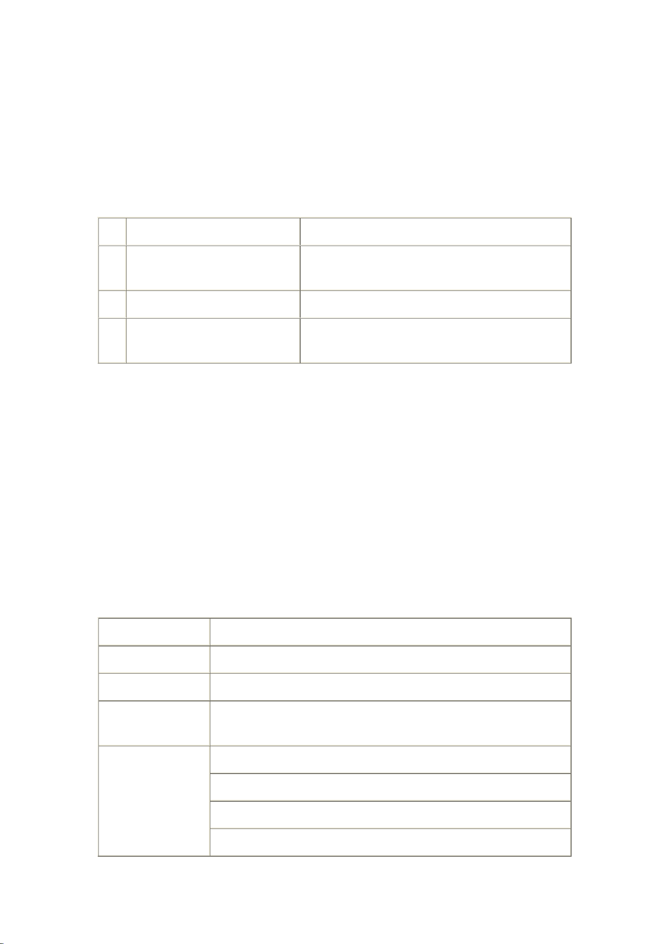
11.1 Common Disconnection Reasons
No.
Disconnection Reason
Solution
1
Overcurrent/Overload
Reduce electrical load or contact power supply
department
2
Overvoltage/Undervoltage
Contact power supply department for handling
3
Meter detects upper cover
opened
Contact power supply department for handling
12 Settlement
The meter supports settlement function, used for electricity information collection
and system billing.
12.1 Monthly Settlement
Note: T for monthly settlement objects: 1-3
Parameter
Content
Storage Capacity
13 times
Settlement Time
Configurable, default 1st of each month 00:00:00
Capture Object
Capacity
Maximum 100
Default Capture
Objects
Time stamp (8, 0-0:1.0.0.255)
Total and per tariff forward active energy (3, 1-0:1.8.T.255)
Total and per tariff reverse active energy (3, 1-0:2.8.T.255)
Total and per tariff forward reactive energy (3, 1-0:3.8.T.255)

Total and per tariff reverse reactive energy (3, 1-0:4.8.T.255)
Total and per tariff combined active energy (3, 1-0:15.8.T.255)
Total forward active energy increment (3, 1-0:1.9.0.255)
Total reverse active energy increment (3, 1-0:2.9.0.255)
Total forward reactive energy increment (3, 1-0:3.9.0.255)
Total reverse reactive energy increment (3, 1-0:4.9.0.255)
Total combined active energy increment (3, 1-0:15.9.0.255)
Total and per tariff forward active maximum demand and occurrence
time (4, 1-0:1.6.T.255)
Total and per tariff reverse active maximum demand and occurrence time
(4, 1-0:2.6.T.255)
12.2 Daily Settlement
Note: T for daily settlement objects: 1-3
Parameter
Content
Storage Capacity
31 days
Settlement Time
Configurable, default daily 00:00:00
Capture Object Capacity
Maximum 100
Default Capture Objects
Time stamp (8, 0-0:1.0.0.255)
Total and per tariff forward active energy (3, 1-0:1.8.T.255)
Total and per tariff reverse active energy (3, 1-0:2.8.T.255)
Total and per tariff forward reactive energy (3, 1-0:3.8.T.255)
Total and per tariff reverse reactive energy (3, 1-0:4.8.T.255)
Total and per tariff combined active energy (3, 1-0:15.8.T.255)
13 Load Curve

The meter's load curve capture period is programmable, different load curves can
be set with different periods.
The meter's load curve capture objects are programmable, different load curves
can be set with different capture objects.
Load curve recorded data can be transmitted to the upper management system via
communication interface or communication module, to draw user's load curve for
more reasonable electricity management.
13.1 Load Curve 1
Parameter
Content
Storage Capacity
8928 records
Capture Period
Configurable, default 15min
Capture Object Capacity
Maximum 100
Default Capture Objects
Time stamp (8, 0-0:1.0.0.255)
Load curve 1 status word (1, 0-0:96.10.1.255)
Forward active power (3, 1-0:1.7.0.255)
Reverse active power (3, 1-0:2.7.0.255)
Forward reactive power (3, 1-0:3.7.0.255)
Reverse reactive power (3, 1-0:4.7.0.255)
Forward active energy (3, 1-0:1.8.0.255)
Reverse active energy (3, 1-0:2.8.0.255)
Forward reactive energy (3, 1-0:3.8.0.255)
Reverse reactive energy (3, 1-0:4.8.0.255)
Total forward active energy increment (3,
1-0:1.9.0.255)

Total reverse active energy increment (3,
1-0:2.9.0.255)
Total forward reactive energy increment (3,
1-0:3.9.0.255)
Total reverse reactive energy increment (3,
1-0:4.9.0.255)
13.2 Load Curve 2
Parameter
Content
Storage Capacity
1560 records
Capture Period
Configurable, default 60min
Capture Object Capacity
Maximum 18
Default Capture Objects
Time stamp (8, 0-0:1.0.0.255)
Load curve 2 status word (0, 0-0:96.10.2.255)
Forward active maximum demand (3,
1-0:1.6.0.255)
Reverse active maximum demand (3,
1-0:2.6.0.255)
Forward reactive maximum demand (3,
1-0:3.6.0.255)
Reverse reactive maximum demand (3,
1-0:4.6.0.255)
14 Events
The meter records the most recent events in each event group, including their
occurrence date/time, in a first-in-first-out manner. Event records can be uploaded
to the upper management computer via communication interface for display,

reporting, and corresponding handling by the power supply management
department.
14.1 Event Grouping
Event grouping, recorded event count, and event capture objects are as follows:
Group
Maximum
Count
Capture Objects
Standard Events
100
Time stamp, event code
Tamper Events
100
Time stamp, event code
Disconnection Events
100
Time stamp, event code
Power Quality Events
100
Time stamp, event code
Communication Events
100
Time stamp, event code
Long Power Failure
Events
100
Time stamp, event code, last long power failure
duration of any phase
14.2 Event Detection
Event
Code
Event Name
Description
Detection
Mechanism
Detection
Threshold
Determination
Time
7
Replace
Battery
Battery needs
replacement
Fixed 3.0V
Fixed 5
seconds
76
Undervoltage
L1
L1 phase
undervoltage
Configurable;
default 90%Un
Configurable;
default 30
seconds
79
Overvoltage
L1
L1 phase
overvoltage
Configurable;
default 110%Un
Configurable;
default 30
seconds
82
Missing
Voltage L1
L1 phase
voltage loss
Configurable;
default 45%Un
Configurable;
default 30
seconds

91
Current
Reversal
Current
reversal
Active power
reverse, and active
power value
greater than
Un*2%Ib
Fixed 10
seconds
/
Power Failure
Long power
failure
Fixed 10%Un
Configurable,
default 180
seconds
14.3 Event Reporting
When the meter is equipped with a communication module, it supports active
reporting of event information to the system end via the module.
The meter supports event supplementary reporting function. After power
restoration, the meter can continue to complete previously unreported events due
to power failure.
14.4 Event Configuration
Event record enable/disable can be configured via upper computer.
Event reporting enable/disable can be configured via upper computer.
15 PUSH
15.1 Data Reporting
The meter supports reporting of the most recent 1 load curve record,
the most recent 1 daily settlement record, and the most recent 1
monthly settlement record.

16 Time-of-Use Tariffs
The meter supports TOU (Time-of-Use) tariff function. TOU parameters can be
configured via upper computer:
Parameter
Maximum
Number
Description
Special Holidays
100
Each special holiday points to a different daily schedule
table.
Season Table
12
Each season table points to a different week table.
Week Table
8
Each week table points to a different daily schedule table.
Daily Schedule
Table
8
Each daily schedule table defines different time periods
corresponding to tariff numbers.
Daily Time
Periods
12
Tariffs
4
Each tariff can independently define different electricity
prices.
The meter supports backup TOU parameters, which can be set via upper computer.
Backup tariff parameter activation time is configurable.
Default tariff:
Season Profile Name
Season Start Time
Week Name
1
FFFF-01-01-00:00:00
01
Week Profile Name
Mon. -> Sun.
01
DT1 DT1 DT1 DT1 DT1 DT1 DT1
day_profile_table_active
00:00
DT1
T1

17 Payment Mode
17.1 Post-payment Mode
The meter normally accumulates energy, does not perform deduction operations,
and does not perform any relay operations. In post-payment mode, the balance
indicator light is green and steady.
In post-payment mode, purchase tokens and clear balance tokens are not
accepted.
18 Common Fault Handling
Fault Phenomenon
Cause Analysis
Handling Method
LCD no display
Power supply
problem
1. Use a multimeter to check if there is voltage on
the meter's voltage terminals.
2. Check if the voltage is connected according to
the rated voltage on the meter nameplate.
LCD display missing
segments, unclear
LCD damaged
Notify the manufacturer or agent to replace the
LCD.
LCD not displaying,
and pulse indicator
light not flashing
Incorrect wiring, or
voltage not within
working range
1. Check if wiring is correct.
2. Check if voltage is within working range.
3. In no-load mode, pulse light stays on; when
applied load exceeds starting power, pulse light
turns off and starts accumulating energy.
Display normal, pulse
indicator light not
flashing when using
electricity
Incorrect wiring or
no load
1. Check if wiring is correct.
2. Confirm if the electricity current is less than
0.4%Ib.
Real-time
measurement values
不符
Voltage and current
wiring does not
match wiring
diagram
Check if voltage and current wiring is correct, if
necessary use a high-precision multimeter and
clamp meter to measure voltage and current
signals;

Also note if current wiring meets requirements, if
incoming and outgoing lines are reversed.
Working beyond
range
The meter's voltage and current measurement
range should not exceed 1.2 times the reference
voltage and maximum current. If the
measurement range seriously exceeds, it may
cause inaccurate processing, and may even burn
the meter. If the meter is found working beyond
range, replace with a larger specification model or
change to a wiring method with transformer ratio;
if a meter with transformer ratio method exceeds
range, consider replacing with a larger ratio
transformer.
Battery symbol
flashing on LCD
Battery
undervoltage
Replace battery.
Communication
unsuccessful
Communication bus
wiring
Please check if the communication bus is reliable
and wiring is correct.
Communication
data information
problem
1. Check if communication settings (e.g., address,
baud rate, parity) are correct.
2. Test by changing normal and abnormal
communication addresses or installation locations
to determine if it's a communication device or
meter fault problem.
3. Check if the communication protocol between
the meter and communication software is
consistent.