JET
427 New Sanford Road
LaVergne, Tennessee 37086 Document No. M-140183
Ph.: 800-274-6848 Edition 2 12/2020
www.jettools.com Copyright © 2020 JET
Operating Instructions and Parts Manual
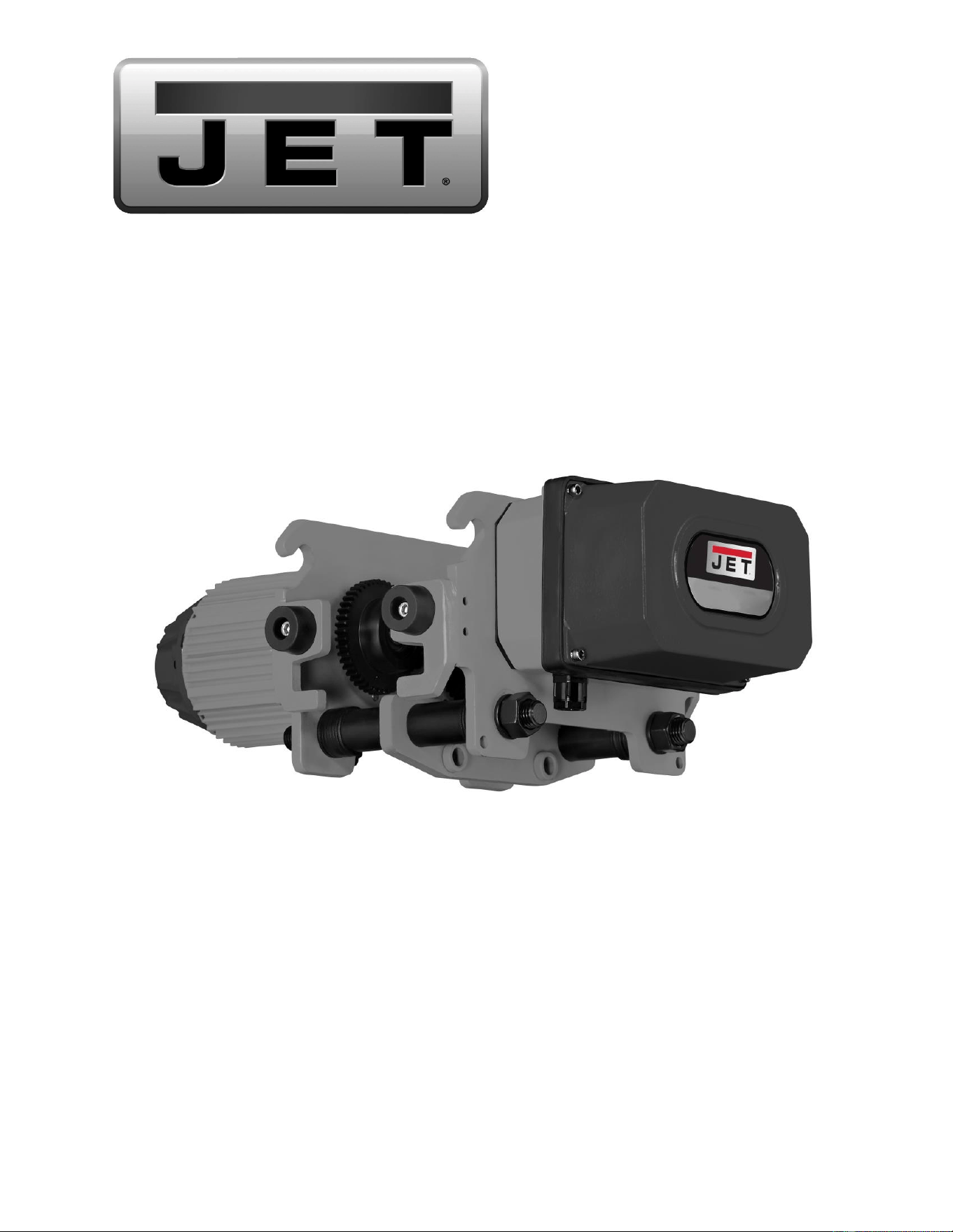
MT Series 2-speed Electric Trolley
2
1.0 IMPORTANT SAFETY INSTRUCTIONS
Read and understand this entire manual
before attempting assembly or operation. You
should also be thoroughly familiar with all
information in the owner’s manual that
accompanied your hoist.
Read and understand the warnings posted on
the machine and in this manual. Failure to
comply with all of these warnings may cause
serious injury.
Replace the warning labels if they become
obscured or removed.
This trolley is designed and intended for use
by properly trained and experienced personnel
only. If you are not familiar with the proper and
safe operation of a trolley, do not use until
proper training and knowledge have been
obtained.
Do not use this trolley for other than its
intended use. If used for other purposes, JET
disclaims any real or implied warranty and
holds itself harmless from any injury that may
result from that use.
Do not install this trolley where explosive
hazards may exist.
Beam must be properly installed and rated for
anticipated loads. Do not install trolley on
beams of unknown capacity.
Do not install trolley on damaged or deformed
beams.
JET trolleys are designed to be used with
hoists of the same rated capacity. Never use a
hoist with a capacity greater than the capacity
of the trolley.
Never subject trolley to a side pull or load.
Load must be centered directly under the
hoist/trolley assembly.
Make sure load is stable and secure before
moving.
Never lift load higher than is necessary to
safely move it.
Do not use to lift people, or loads over people.
Warn others in the vicinity when lifting or
transporting a load. Avoid swinging load and
hook.
Do not use in wet, damp or poorly lit locations.
This trolley is not rated for outdoor use.
Do not exceed the rated capacity of the trolley.
Maintain firm footing when operating the trolley.
The exposed end of the beam or rail must
have a stop installed to contact the frame
sides of the trolley, to prevent the trolley from
sliding off the beam/rail.
Always inspect the trolley for damage prior to
use. If the trolley is damaged, do not use until
it has been repaired or replaced.
Leave all internal maintenance to a qualified
JET service center.
Do not operate this trolley while tired or under
the influence of drugs, alcohol or any
medication.
Thoroughly familiarize yourself with all
instructions that accompanied the hoist you
will be using with this trolley.
Anticipate stopping points and allow the trolley
to come to a smooth stop. Avoid sudden stops
or reversals.
Familiarize yourself with the following safety
notices used in this manual:
This means that if precautions
are not heeded, it may result in minor injury and/or
possible machine damage.
This means that if precautions
are not heeded, it may result in serious injury or
possibly even death.
- - SAVE THESE INSTRUCTIONS - -
WARNING: This product can expose you to
chemicals including lead and cadmium which
are known to the State of California to cause
cancer and birth defects or other reproductive
harm, and phthalates which are known to the
State of California to cause birth defects or
other reproductive harm. For more information
go to http://www.p65warnings. ca.gov.

3
2.0 Table of Contents
1.0 IMPORTANT SAFETY INSTRUCTIONS ....................................................................................................... 2
2.0 Table of Contents ........................................................................................................................................... 3
3.0 Introduction .................................................................................................................................................... 4
4.0 MT Trolley Specifications ............................................................................................................................... 5
4.1 230 volt models .......................................................................................................................................... 5
4.2 460 volt models .......................................................................................................................................... 6
4.3 MT trolley with TS series hoist – dimensions ............................................................................................. 7
5.0 Unpacking ...................................................................................................................................................... 8
5.1 Contents of Shipping Container ................................................................................................................. 8
6.0 Installation & Assembly .................................................................................................................................. 8
6.1 Mount trolley to beam ................................................................................................................................. 8
6.2 Mount hoist to trolley .................................................................................................................................. 8
7.0 Electrical connections .................................................................................................................................. 10
7.1 GROUNDING INSTRUCTIONS ............................................................................................................... 10
7.2 Extension Cords ....................................................................................................................................... 10
7.3 Inspecting trolley motion ........................................................................................................................... 10
8.0 User-maintenance ........................................................................................................................................ 11
8.1 Brake inspection ....................................................................................................................................... 11
8.2 Lubrication ................................................................................................................................................ 11
8.3 Additional servicing .................................................................................................................................. 11
9.0 Pendant controllers for Trolley with TS Hoist ............................................................................................... 11
10.0 Troubleshooting MT Series Trolleys .......................................................................................................... 12
11.0 Replacement Parts ..................................................................................................................................... 13
11.1.1 MT050 and MT100 Trolley Frame – Exploded View ........................................................................... 14
11.1.2 MT050 and MT100 Trolley Frame – Parts List .................................................................................... 15
11.2.1 MT050 and MT100 Trolley Motor – Exploded View ............................................................................ 16
11.2.2 MT050 and MT100 Trolley Motor – Parts List ..................................................................................... 17
11.3.1 MT050 and MT100 Trolley Electricals – Exploded View ..................................................................... 18
11.3.2 MT050 and MT100 Trolley Electricals – Parts List .............................................................................. 18
11.4.1 MT200 Trolley Frame – Exploded View .............................................................................................. 19
11.4.2 MT200 Trolley Frame – Parts List ....................................................................................................... 20
11.5.1 MT200 Trolley Motor – Exploded View ............................................................................................... 21
11.5.2 MT200 Trolley Motor – Parts List ........................................................................................................ 22
11.6.1 MT200 Trolley Electricals – Exploded View ........................................................................................ 23
11.6.2 MT200 Trolley Electricals – Parts List ................................................................................................. 23
11.7.1 MT300 and MT500 Trolley Frame – Exploded View ........................................................................... 24
11.7.2 MT300 and MT500 Trolley Frame – Parts List .................................................................................... 25
11.8.1 MT300 and MT500 Trolley Motor – Exploded View ............................................................................ 26
11.8.2 MT300 and MT500 Trolley Motor – Parts List ..................................................................................... 27
11.9.1 MT300 and MT500 Trolley Electricals – Exploded View ..................................................................... 28
11.9.2 MT300 and MT500 Trolley Electricals – Parts List .............................................................................. 28
12.0 Electrical connections ................................................................................................................................ 29
12.1 MT Trolley wiring .................................................................................................................................... 29
13.0 Warranty and Service ................................................................................................................................. 30

4
3.0 Introduction
This manual is provided by JET covering the safe operation and maintenance procedures for a JET MT Series
Electric Trolley. This manual contains instructions on installation, safety precautions, general operating
procedures, maintenance instructions and parts breakdown.
The JET MT trolley ranges from 1/2 ton to 5 ton and is designed to pair with a TS series JET hoist. The trolley
is made of thick steel elements, including side plates, wheel axles, suspension bolts, and center load plate.
Wheels are hot-forged steel, and hardened steel comprises the gears and pinion, which is driven by a planetary
gear reducer. Extensions are available to accommodate the width of most beam flanges.
This machine has been designed and constructed to provide consistent, long-term operation if used in
accordance with instructions set forth in this manual. If there are any questions or comments, please contact
either your local supplier or JET. JET can also be reached at our web site: www.jettools.com.
Record your purchase information here for quick reference:
Model No.:
Stock No.:
Serial No.:
Purchased From:
Date Purchased:
Date Installed:
Installer:
The specifications in this manual were current at time of publication, but because of our policy of continuous
improvement, JET reserves the right to change specifications at any time and without prior notice, without incurring
obligations.
5
4.0 MT Trolley Specifications
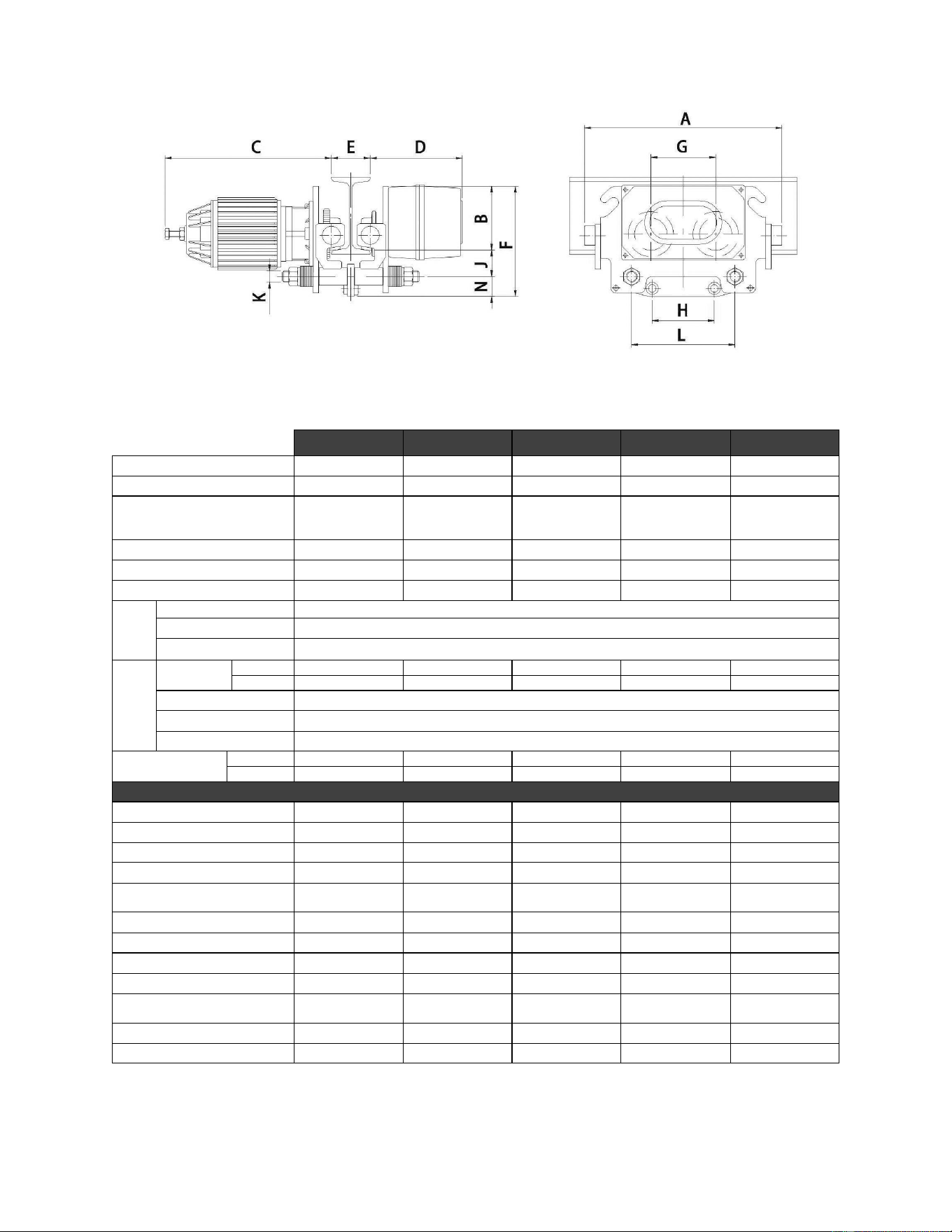
Figure 4-1: Trolley specs
4.1 230 volt models
MT050
MT100
MT200
MT300
MT500
Stock no.
140183
140185
140187
140189
140190
Capacity
1/2 ton (500 kg)
1 ton (1000 kg)
2 ton (2000 kg)
3 ton (3000 kg)
5 ton (5000 kg)
Travel speed
FPM
(MPM)
79 / 20 fpm
(24 / 6 mpm)
79 / 20 fpm
(24 / 6 mpm)
79 / 20 fpm
(24 / 6 mpm)
79 / 20 fpm
(24 / 6 mpm)
79 / 20 fpm
(24 / 6 mpm)
Minimum radius of curve
4.25 ft. (1.3m)
4.25 ft. (1.3m)
5.5 ft. (1.7m)
6.5 ft. (2.0m)
6.5 ft. (2.0m)
Net weight
99 lbs. (45 kg)
99 lbs. (45 kg)
126 lbs. (57 kg)
196.2 lbs. (89 kg)
196.2 lbs. (89 kg)
Shipping weight
143 lbs. (64.8 kg)
143 lbs. (64.8 kg)
170 lbs. (77 kg)
243 lbs. (110 kg)
243 lbs. (110 kg)
Duty
Cycle
Time Rating
30 min
Duty Rating
H4 (40/20%)
Max.starts per hour
240
Motor
Horsepower
High Spd
0.16
0.24
0.5
0.8
0.8
Low Spd
0.04
0.05
0.12
0.2
0.2
Cycle
60 Hz
Phase
3 phase
Voltage
230V
Current Draw
(amperage)
High Spd
0.8
1.2
2.2
3.8
3.8
Low Spd
0.6
0.9
1.7
2.2
2.2
Dimensions (Figure 5-1)
A
15in (382mm)
15in (382mm)
15.4in (392mm)
17.4in (442mm)
17.4in (442mm)
B
4.9in (124.5mm)
4.9in (124.5mm)
4.92in (125mm)
5.3in (135mm)
5.3in (135mm)
C
12.8in (324mm)
12.8in (324mm)
14in (357mm)
15.6in (395mm)
15.6in (395mm)
D
7in (180mm)
7in (180mm)
7.2in (183mm)
7.2in (185mm)
7.2in (185mm)
E*
2.95~4.9in
(75~125mm)
2.95~4.9in
(75~125mm)
3.93~5.9in
(100~150mm)
4.9~6.9in
(125~175mm)
4.9~6.9in
(125~175mm)
F
8.5in (217mm)
8.5in (217mm)
8.7in (221mm)
11.2in (285mm)
11.2in (285mm)
G
4.9in (125.5mm)
4.9in (125.5mm)
6.3in (159mm)
7.3in (185mm)
7.3in (185mm)
H
3.8in (95.5mm)
4.7in (120mm)
2.1in (52.5mm)
2.1in (52.5mm)
2.1in (52.5mm)
J
2in (51.5mm)
2in (51.5mm)
2.4in (60mm)
2.8in (70mm)
2.8in (70mm)
K
7/8”-9UNC
(Ø 22.2mm)
1”-8UNC
(Ø 25.4mm)
1-1/4”-7UNC
(Ø 31.75mm)
1-1/2”-6UNC
(Ø 38.1mm)
1-3/4”-5UNC
(Ø 44.5mm
L
7.9in (200mm)
7.9in (200mm)
9in (230mm)
9.8in (250mm)
9.8in (250mm)
N
1.6in (41mm)
1.6in (41mm)
1.4in (36mm)
2.3in (57.5mm)
2.3in (57.5mm)
Table 1
* The trolley can be extended for greater “E” widths than what are shown in the chart. See the optional
extension kits listed in the appropriate parts list for each machine.
6
4.2 460 volt models
MT050-4
MT100-4
MT200-4
MT300-4
MT500-4
Stock no.
144183
144185
144187
144189
144190
Capacity
1/2 ton (500 kg)
1 ton (1000 kg)
2 ton (2000 kg)
3 ton (3000 kg)
5 ton (5000 kg)
Travel speed
FPM
(MPM)
79 / 20 fpm
(24 / 6 mpm)
79 / 20 fpm
(24 / 6 mpm)
79 / 20 fpm
(24 / 6 mpm)
79 / 20 fpm
(24 / 6 mpm)
79 / 20 fpm
(24 / 6 mpm)
Minimum radius of curve
4.25 ft. (1.3m)
4.25 ft. (1.3m)
5.5 ft. (1.7m)
6.5 ft. (2.0m)
6.5 ft. (2.0m)
Net weight
99 lbs. (45 kg)
99 lbs. (45 kg)
126 lbs. (57 kg)
196.2 lbs. (89 kg)
196.2 lbs. (89 kg)
Shipping weight
143 lbs. (64.8 kg)
143 lbs. (64.8 kg)
170 lbs. (77 kg)
243 lbs. (110 kg)
243 lbs. (110 kg)
Duty
Cycle
Time Rating
30 min
Duty Rating
H4 (40/20%)
Max.starts per hour
240
Motor
Horsepower
High Spd
0.16
0.24
0.5
0.8
0.8
Low Spd
0.04
0.05
0.12
0.2
0.2
Cycle
60 Hz
Phase
3 phase
Voltage
460V
Current Draw
(amperage)
High Spd
0.4
0.6
1.1
1.9
1.9
Low Spd
0.3
0.5
0.8
1.1
1.1
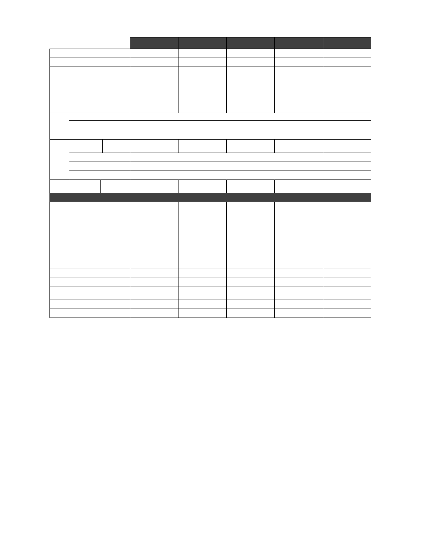
Dimensions (Figure 5-1)
A
15in (382mm)
15in (382mm)
15.4in (392mm)
17.4in (442mm)
17.4in (442mm)
B
4.9in (124.5mm)
4.9in (124.5mm)
4.92in (125mm)
5.3in (135mm)
5.3in (135mm)
C
12.8in (324mm)
12.8in (324mm)
14in (357mm)
15.6in (395mm)
15.6in (395mm)
D
7in (180mm)
7in (180mm)
7.2in (183mm)
7.2in (185mm)
7.2in (185mm)
E*
2.95~4.9in
(75~125mm)
2.95~4.9in
(75~125mm)
3.93~5.9in
(100~150mm)
4.9~6.9in
(125~175mm)
4.9~6.9in
(125~175mm)
F
8.5in (217mm)
8.5in (217mm)
8.7in (221mm)
11.2in (285mm)
11.2in (285mm)
G
4.9in (125.5mm)
4.9in (125.5mm)
6.3in (159mm)
7.3in (185mm)
7.3in (185mm)
H
3.8in (95.5mm)
4.7in (120mm)
2.1in (52.5mm)
2.1in (52.5mm)
2.1in (52.5mm)
J
2in (51.5mm)
2in (51.5mm)
2.4in (60mm)
2.8in (70mm)
2.8in (70mm)
K
7/8”-9UNC
(Ø 22.2mm)
1”-8UNC
(Ø 25.4mm)
1-1/4”-7UNC
(Ø 31.75mm)
1-1/2”-6UNC
(Ø 38.1mm)
1-3/4”-5UNC
(Ø 44.5mm
L
7.9in (200mm)
7.9in (200mm)
9in (230mm)
9.8in (250mm)
9.8in (250mm)
N
1.6in (41mm)
1.6in (41mm)
1.4in (36mm)
2.3in (57.5mm)
2.3in (57.5mm)
Table 2
* The trolley can be extended for greater “E” widths than what are shown in the chart. See the optional
extension kits listed in the appropriate parts list for each machine.
7
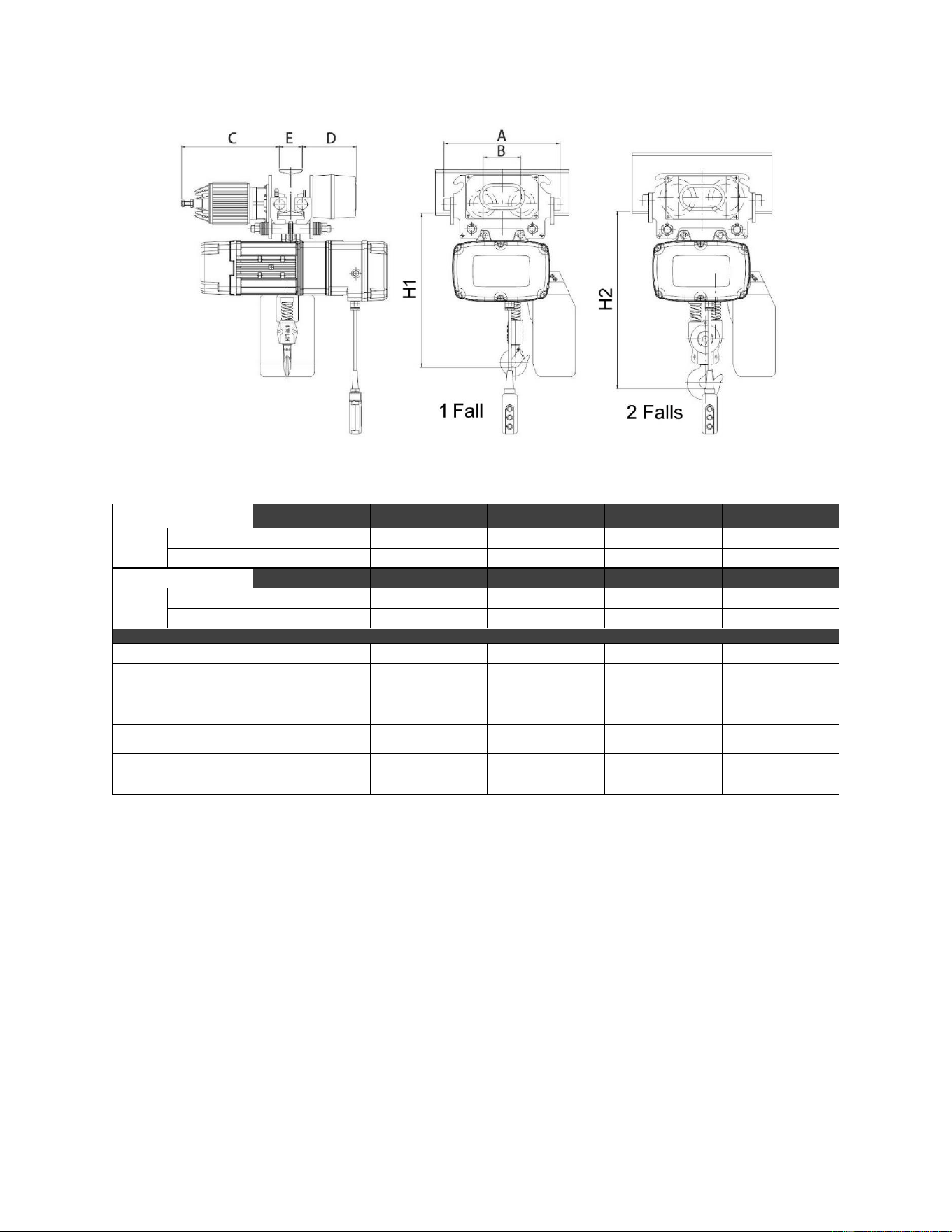
4.3 MT trolley with TS series hoist – dimensions
MT Trolleys are designed to pair with the TS hoists. Voltage of trolley must match voltage of hoist.
Figure 4-2
Hoist model 230V
TS050-230
TS100-230
TS200-230
TS300-230
TS500-230
Trolley
230V
model no.
MT050
MT100
MT200
MT300
MT500
stock no.
140183
140185
140187
140189
140190
Hoist model 460V
TS050-460
TS100-460
TS200-460
TS300-460
TS500-460
Trolley
460V
model no.
MT050-4
MT100-4
MT200-4
MT300-4
MT500-4
stock no.
144183
144185
144187
144189
144190
A
15-3/16" (385mm)
15-3/16" (385mm)
15-9/16" (395mm)
17-1/2" (445mm)
17-1/2" (445mm)
B
4-15/16" (126mm)
4-15/16" (126mm)
6-1/4" (159mm)
7-5/16" (185mm)
7-5/16" (185mm)
C
12-13/16" (325mm)
12-13/16" (325mm)
14-3/16" (360mm)
15-3/4" (400mm)
15-3/4" (400mm)
D
7-1/16" (180mm)
7-1/16" (180mm)
7-5/16" (185mm)
7-11/16" (195mm)
7-11/16" (195mm)
E*
2-15/16~4-15/16"
(75~125mm)
2-15/16~4-15/16"
(75~125mm)
3-15/16~5-7/8"
(100~150mm)
4-15/16~6-7/8"
(125~175mm)
4-15/16~6-7/8"
(125~175mm)
H1
19-11/16" (500mm)
21-1/16" (535mm)
38-3/16" (970mm)
-----
-----
H2
-----
-----
-----
39-3/8" (1000mm)
41-5/16" (1050mm)
Table 3
* The trolley can be extended for greater “E” widths than what are shown in the chart. See the optional
extension kits which are listed in the appropriate parts list for each machine.
8
Read and understand the entire contents of this
manual before attempting assembly or
operation. Failure to comply may cause serious
injury.
5.0 Unpacking
Open shipping container and check for shipping
damage. Report any damage immediately to your
distributor and shipping agent. Do not discard any
shipping material until the Trolley is assembled and
running properly.
Compare the contents of your container with the
following parts list to make sure all parts are intact.
Missing parts, if any, should be reported to your
distributor. Read the instruction manual thoroughly
for assembly, maintenance and safety instructions.
5.1 Contents of Shipping Container
1 Electric Trolley
1 Owner's manual
1 Product registration card
1 Test report
6.0 Installation & Assembly
The MT Series trolley is designed to run on
standard “I” beams, wide-flanged “H” beams, or
curved track with a minimum radius shown in the
chart in sect. 5.0.
6.1 Mount trolley to beam
The trolley is heavy; use an
assistant or a lifting device to help stabilize it
while you assemble it to the beam.
Note: Mount the trolley to the beam first before
mounting a hoist to it.
1. Measure the width of the beam flange on
which the trolley will operate. This is important
as beam flanges may vary in width. See sect.
4.1 for the beam width range for your specific
trolley.
2. Determine the arrangement of spacer washers
between the trolley side frames based upon
the measurement. Spacers must be moved in
sets of two to maintain centerline of trolley.
Distance between trackwheel flanges should
be 1/8- to 2-inches (3 to 5mm) greater than the
beam flange width for straight runway beams,
and 3/16- to 9/32-inches (5 to 7mm) for
sharply curved beams.
3. Loosely assemble side frames, position tubes,
spacer washers and nuts on the stay bolts.
See Figure 6-1.
4. Install the trolley on the beam by sliding one
side plate out enough to allow trackwheels to
clear the beam.
5. Make sure the trackwheels are riding on the
beam, and draw the side plates together.
Tighten the nuts securely.
Note: If the trolley sits at a slight angle, this is
normal. The weight of the hoist or load will
level it to horizontal.
Figure 6-1
End stops must be installed at the exposed ends of
a beam. These will be contacted by the rubber
bumpers on the trolley to help cushion impact.
Open-end beams must have
the proper end stops installed to prevent the
trolley from running off the beam. Failure to
comply may cause serious injury and/or
property damage.
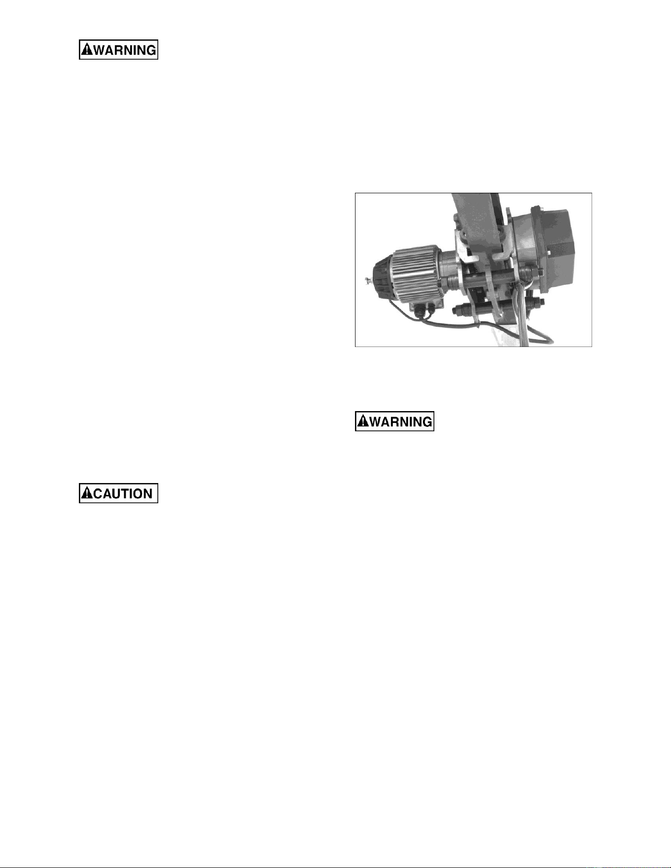
6.2 Mount hoist to trolley
This trolley has been designed to accommodate
the JET TS-Series Hoist. They can be connected
so that one pendant cord and power cord will
operate both trolley and hoist. Make sure the hoist
has been set to the same voltage specifications as
the trolley, and matches the size and load capacity
of the hoist that will be connected to it.
1. The trolley has been assembled to the beam.
However, the trolley should also be stabilized
by an additional support system, such as
chains, until the hoist mounting system is
completed. See Figure 6-2.
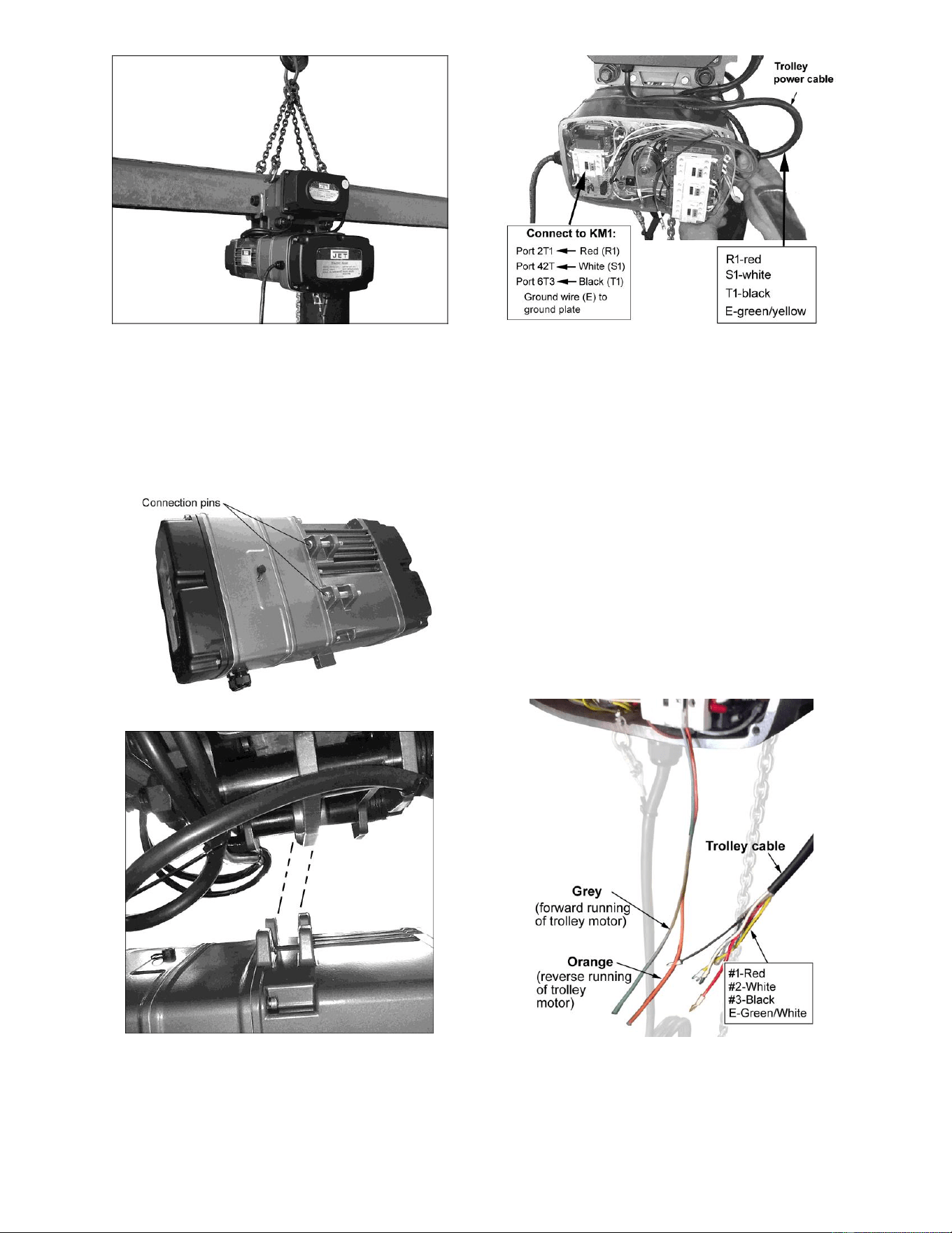
9
Figure 6-2
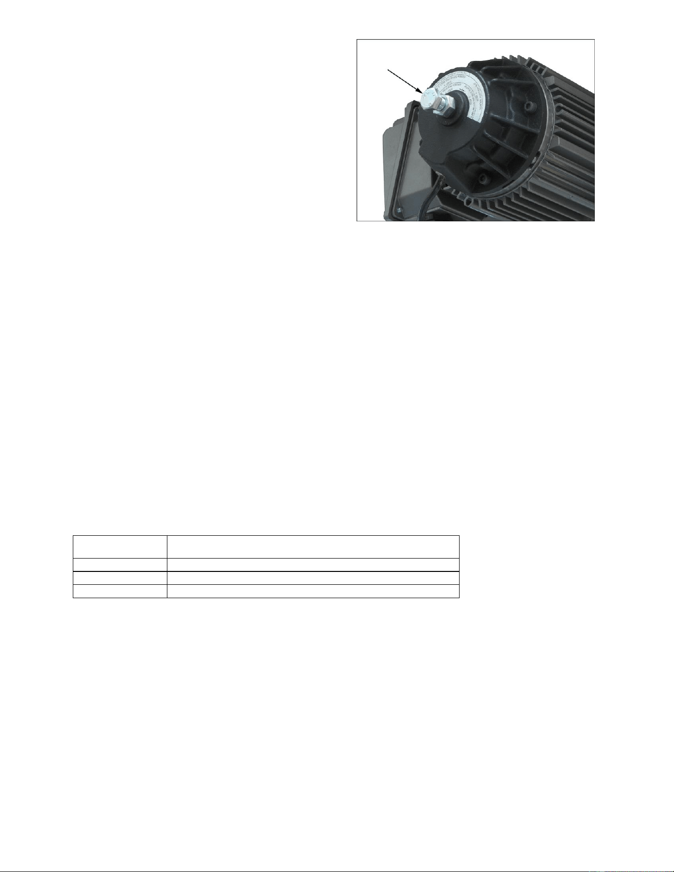
2. Align tabs on top of hoist (Figures 6-3,6-4) to
holes on underside of trolley. Secure with the
existing pins, washers and hex nuts.
The hoist should be oriented so that the
electrical strain reliefs on hoist and trolley are
at the same end. Make sure hoist is securely
mounted.
Figure 6-3
Figure 6-4
3. Bring the trolley power cable into the hoist
through the cable gland. See Figure 6-5.
Connect the four wires from the trolley cable to
the KM1 contactor, as described in Figure 6-5.
Figure 6-5
4. Locate the grey and orange wires in the hoist.
See Figure 6-6. The grey wire will control the
forward movement of the trolley. The orange
wire will control the reverse movement of the
trolley.
5. Bring the trolley control cable through the
second gland on the same side of the hoist,
and connect it as follows.
Connect #1 Red wire to port A2 of the KM3
contactor.
Connect #2 White wire to the grey wire.
Connect #3 Black wire to the orange wire.
Connect E grounding wire to the ground plate.
Note: if you connect the #2 White wire to the
orange wire (instead of the grey), the motor
movement will be reversed.
Figure 6-6
6. Trolley and hoist are now connected. Remove
the chain support from atop the trolley.
7. Proceed to sect. 7.0 for electrical connections.

10
7.0 Electrical connections
Electrical connections must be
made by a qualified electrician in compliance
with all relevant codes. This machine must be
properly grounded to help prevent electrical
shock and possible fatal injury.
7.1 GROUNDING INSTRUCTIONS
In the event of a malfunction or breakdown,
grounding provides a path of least resistance for
electric current to reduce the risk of electric shock.
The trolley power cord must be correctly wired into
the hoist, and the hoist power cord must be fitted
with an appropriate UL/CSA listed plug, or can be
“hard-wired” directly to a control panel. If hard-
wired, make sure a disconnect is available for the
operator.
If a plug is installed, it must have an equipment-
grounding conductor and a grounding prong. The
plug must be plugged into a matching outlet that is
properly installed and grounded in accordance with
all local codes and ordinances. Do not modify the
plug.
Improper connection of the equipment-grounding
conductor can result in a risk of electric shock. The
conductor with insulation having an outer surface
that is green with or without yellow stripes is the
equipment-grounding connector. If repair or
replacement of the electric cord or plug is
necessary, do not connect the equipment-
grounding conductor to a live terminal.
Check with a qualified electrician or service
personnel if the grounding instructions are not
completely understood, or if in doubt as to whether
the tool is properly grounded.
Repair or replace damaged or worn cord
immediately.
7.2 Extension Cords
If an extension cord is necessary, make sure the
cord rating is suitable for the amperage listed on
the trolley’s motor plate. An undersize cord will
cause a drop in line voltage resulting in loss of
power and overheating.
The chart in Table 3 shows the correct size cord to
use based on cord length and motor plate amp
rating. If in doubt, use the next heavier gauge. The
smaller the gauge number, the heavier the cord.
Recommended Gauges (AWG) of Extension Cords
Amps
Extension Cord Length *
25
feet
50
feet
75
feet
100
feet
150
feet
200
feet
< 5
16
16
16
14
12
12
5 to 8
16
16
14
12
10
NR
8 to 12
14
14
12
10
NR
NR
12 to 15
12
12
10
10
NR
NR
15 to 20
10
10
10
NR
NR
NR
21 to 30
10
NR
NR
NR
NR
NR
*based on limiting the line voltage drop to 5V at 150% of the
rated amperes.
NR: Not Recommended.
Table 4
7.3 Inspecting trolley motion
1. Before closing the circuit breaker and testing
the trolley, check that wiring has been
complete. If the trolley cannot be observed
when the circuit breaker is closed, station an
observer within sight of the trolley to report any
movement when power is applied to the trolley.
Be prepared to disconnect power if trolley
motor starts when the power is applied. The
trolley must remain motionless when power is
applied. Find and correct any problems before
continuing.
2. After all assembly and wiring is complete,
operate trolley forward and back a short
distance, then do likewise for the entire length
of the beam. Confirm that all adjustments and
operations are satisfactory.
11
8.0 User-maintenance
The trolley should be inspected on a routine basis,
with particular attention to these:
Tightness of all fasteners
Cables/leads for broken wires, corroded or
loose terminals, damaged insulation.
Contactors and pendant controls for loose or
corroded terminals.
Trackwheels for worn tread, flanges, or
bearings.
Trackwheel gears and pinion for wear.
8.1 Brake inspection
The motor brake should be inspected periodically
for wear of brake lining and disc. If either is worn
so that the brake cannot perform efficiently, they
should be replaced.
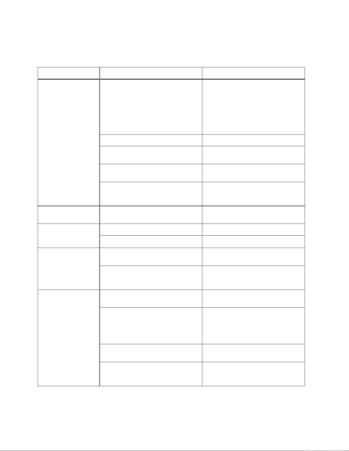
The gap between brake lining and disc can be
adjusted by the bolt shown in Figure 8-1.
Loosen nut and fully tighten adjustment bolt. Then
loosen the bolt two rotations. Retighten nut against
motor housing to secure setting.
Figure 8-1
8.2 Lubrication
Monthly lubricate the track wheel gear and pinion
with grease.
Change out the motor gearbox grease after 100
hours of operation, then every 6 months or 2500
hours of normal service. Use a No. 3 grease, such
as Mobil Cup Grease 3 or equivalent.
8.3 Additional servicing
Any other servicing should be performed by an
authorized service representative.
9.0 Pendant controllers for Trolley with TS Hoist
Part no.
Description
140196
WIRED PENDANT, 4-BTN, TS+MT, for 10FT Hoist
140197
WIRED PENDANT, 4-BTN, TS+MT, for 15FT Hoist
140198
WIRED PENDANT, 4-BTN, TS+MT, for 20FT Hoist
Table 5
12
10.0 Troubleshooting MT Series Trolleys
Table 6
WARNING: Some remedies may required a qualified electrician.
Trouble
Probable Cause
Remedy
Trolley will not
operate, or operates
intermittently.
No incoming power, or low voltage.
Check trolley connections to power
source. Make sure power source
matches specifications on trolley name
plate. If low voltage, have certified
electrician check incoming power.
Voltage that falls outside of +/-10% of
rated power will result in improper
operation and potential motor damage.
Fuse blown or circuit breaker tripped.
Replace fuse/reset circuit breaker.
Improper connections between trolley
and TS model JET hoist.
Inspect wiring connections; review
instructions.
Conductors in pendant cord damaged.
Check for continuity in each conductor.
If faulty, replace entire pendant cord.
Motor damaged.
Have motor inspected and repaired/
replaced by a qualified service
technician.
Trolley performs
slugglishly
Rail/beam is dirty or worn.
Clean rail as part of regular inspection
process.
Trolley continues
movement after brake
applied.
Grease or oil on the brake lining.
Disassemble brake and clean the lining.
Brake pad is worn or damaged.
Replace brake pad.
Hoist moves in wrong
direction.
Two of the three power supply wires are
switched.
Switch any two of the three supply
wires.
Improper connections with hoist. (#2
white wire connected to orange instead
of grey wire.)
Review instructions and rewire.
Motor overheats.
Excessive load or too frequent use.
Operate within rated load and according
to duty cycle rating.
Low voltage.
Have certified electrician check
incoming power. Voltage that falls
outside of +/-10% of rated power will
result in improper operation and
potential motor damage.
Brake is dragging.
Have brake repaired or replaced by a
qualified service technician.
Ambient temperature exceeds normal
range.
Reduce operating times of the trolley.
Use measures to help shield the trolley
from excessive ambient heat.

13
11.0 Replacement Parts
Replacement parts are listed on the following pages. To order parts or reach our service department, call 1-
800-274-6848 Monday through Friday, 8:00 a.m. to 5:00 p.m. CST. Having the Model Number and Serial
Number of your machine available when you call will allow us to serve you quickly and accurately.
Non-proprietary parts, such as fasteners, can be found at local hardware stores, or may be ordered from JET.
Some parts are shown for reference only, and may not be available individually.
NOTE: If an item shows two part numbers, the trolley model on which it is used can be identified by the part
number.
14
11.1.1 MT050 and MT100 Trolley Frame – Exploded View

15
11.1.2 MT050 and MT100 Trolley Frame – Parts List
Index No. Part No. Description Size Qty
1 ................ MT050-A01 ............... Electric Frame Assembly ......................................... ...................................... 1
.................. MT100-A01 ............... Electric Frame Assembly ......................................... ...................................... 1
2 ................ F006035 .................... C-Retaining Ring, Int ............................................... R-40 .............................. 4
3 ................ BB-6203ZZ ................ Bearing ................................................................... 6203ZZ.......................... 4
4 ................ MT050-A04 ............... Plain Wheel ............................................................. Ø 88×28L ....................... 2
5 ................ F006045 .................... C-Retaining Ring, Ext .............................................. S-17 .............................. 4
6 ................ MT050-A06 ............... Gear Wheel ............................................................. M2×46T×33L................. 2
7 ................ MT050-A07 ............... Motor Frame Assembly............................................ ...................................... 1
.................. MT100-A07 ............... Motor Frame Assembly............................................ ...................................... 1
8 ................ MT050-A08 ............... Stay Bolt ................................................................. 7/8"×9UNC×265L .......... 2
.................. MT100-A08 ............... Stay Bolt ................................................................. 1"×8UNC×265L ............. 2
9 ................ MT050-A09 ............... Position Tube .......................................................... Ø 34×Ø 24×56L .............. 4
.................. MT100-A09 ............... Position Tube .......................................................... Ø 38×Ø 28×56L .............. 4
10 .............. MT050-A10 ............... Load Bracket............................................................ ...................................... 1
.................. MT100-A10 ............... Load Bracket............................................................ ...................................... 1
11 .............. MT050-A11 ............... Spacer Washer ....................................................... Ø 40×Ø 24×1/8" ............ 32
.................. MT100-A11 ............... Spacer Washer ....................................................... Ø 46×Ø 27×1/8" ............ 32
12 .............. MT050-A12 ............... Spring Washer ........................................................ 7/8" ................................ 4
.................. MT100-A12 ............... Spring Washer ........................................................ 1" ................................... 4
13 .............. MT050-A13 ............... Hex. Nut .................................................................. 7/8"×9UNC .................... 4
.................. MT100-A13 ............... Hex. Nut .................................................................. 1”x8UNC ....................... 4
14 .............. MT050-A14 ............... Bumper .................................................................... ...................................... 4
15 .............. TS-2361101 .............. Spring Washer ........................................................ M10 ............................... 4
16 .............. TS-1491021 .............. Hex. Head Bolt ....................................................... M10×1.5×20L ................ 4
17 .............. MT050-A17 ............... Motor Assembly....................................3~230V,60Hz,0.12/0.03kW ............... 1
.................. MT100-A17 ............... Motor Assembly....................................3~230V,60Hz,0.18/0.04kW ............... 1
Extension Kit Accessories for MT050 and MT100
Part No. Description “E” width, sect. 4.0
MT050-A08AB ........ Includes #8, #9, #11~#13 .............................. 4.96~8.26 in. (126~210mm) .......... OPTIONAL
MT050-A08AC ....... Includes #8, #9, #11~#13 .............................. 8.3~12.2 in. (211~310mm) ............ OPTIONAL
MT100-A08AB ........ Includes #8, #9, #11~#13 .............................. 4.96~8.26 in. (126~210mm) .......... OPTIONAL
MT100-A08AC ....... Includes #8, #9, #11~#13 .............................. 8.3~12.2 in. (211~310mm) ............ OPTIONAL
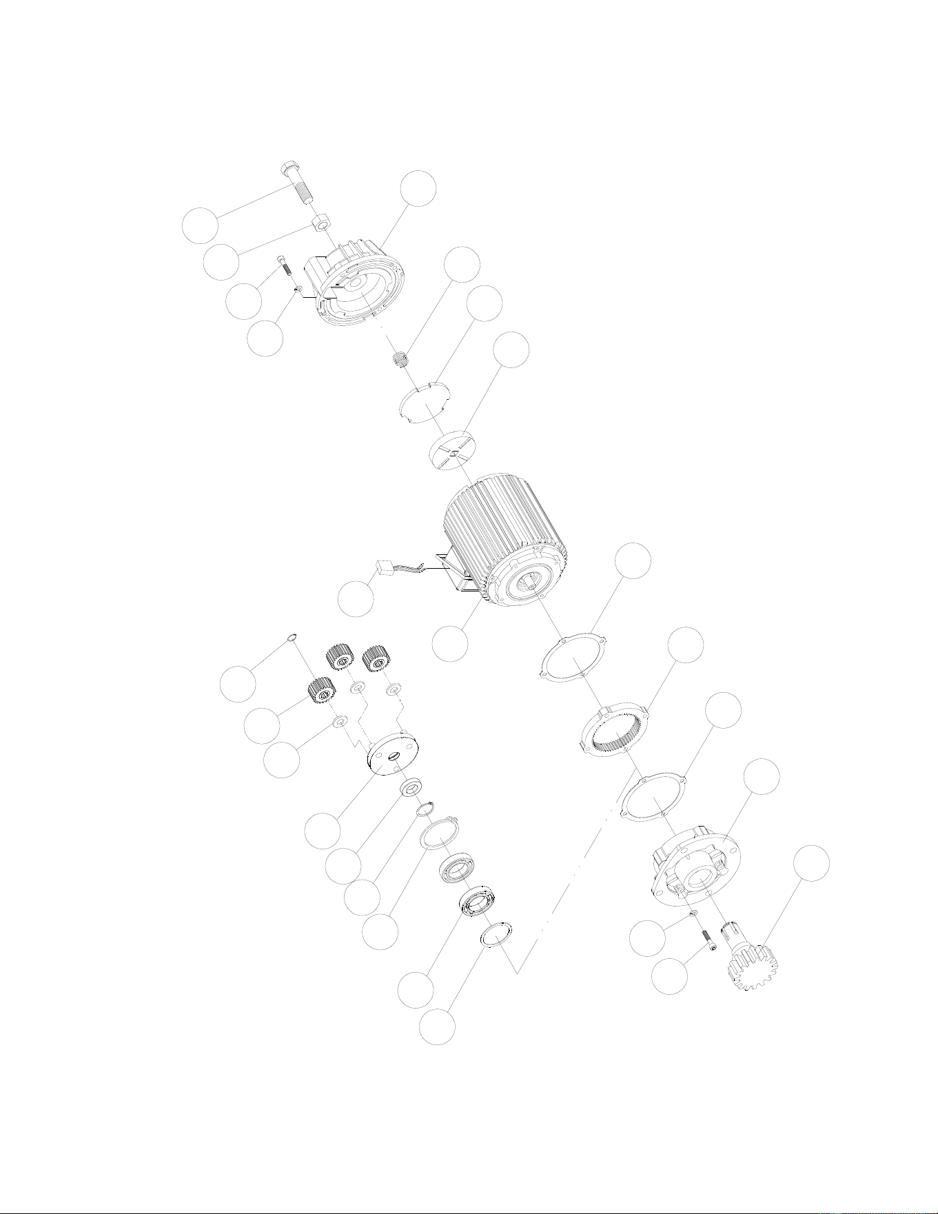
16
11.2.1 MT050 and MT100 Trolley Motor – Exploded View
23
17
18
11
10
20
19
22
21
1
5
2
3
4
6
13
12
24
8
9
7
19
16
15
14
11

17
11.2.2 MT050 and MT100 Trolley Motor – Parts List
Index No. Part No. Description Size Qty
1 ................ MT050-B01 ............... Oil Seal ................................................................... Ø 25×Ø 40×6t ................. 1
2 ................ BB-6204Z .................. Bearing ................................................................... 6204Z ............................ 2
3 ................ F006075 .................... C-Retaining Ring, Int ............................................... R-47 .............................. 1
4 ................ F006047 .................... C-Retaining Ring, Ext .............................................. S-20 .............................. 1
5 ................ MT050-B05 ............... Axle Sleeve .............................................................. ...................................... 1
6 ................ MT050-B06 ............... Reducing Gear Frame Assembly............................. ...................................... 1
7 ................ MT050-B07 ............... Flat Washer ............................................................ Ø 21×Ø 11×2t ................. 3
8 ................ MT050-B08 ............... Planetary Gear......................................................... ...................................... 3
9 ................ F006040 .................... C-Retaining Ring, Ext .............................................. S-10 .............................. 3
10 .............. MT050-B10 ............... Hex. Head Bolt ....................................................... M6×1×60L ..................... 4
11 .............. TS-2361061 .............. Spring Washer ........................................................ M6 ................................. 8
12 .............. MT050-B12 ............... Motor Stator Assembly...........................3~230V60Hz0.12/0.03kW ............... 1
.................. MT050-B12M ............ Motor Stator Assembly .......................... 3~460V60Hz0.12/0.03kW ............... 1
.................. MT100-B12 ............... Motor Stator Assembly ..........................3~230V60Hz0.18/0.04kW ............... 1
.................. MT100-B12M ............ Motor Stator Assembly .......................... 3~460V60Hz0.18/0.04kW ............... 1
13 .............. MT050-B13 ............... Rectifier.................................................................... ...................................... 1
14 .............. TS-1482041 .............. Hex. Head Bolt ........................................................ M6×1.0×20L .................. 4
15 .............. TS-1540081 .............. Nut .......................................................................... M12×1.75 ...................... 1
16 .............. TS-1492021 .............. Hex. Head Bolt ....................................................... M12×1.75×30L .............. 1
17 .............. MT050-B17 ............... Transmission Shaft With Pinion ............................... ...................................... 1
18 .............. MT050-B18 ............... Gear Box.................................................................. ...................................... 1
19 .............. MT050-B19 ............... Gear Box Gasket .................................................... ...................................... 2
20 .............. MT050-B20 ............... Internal Ring Gear .................................................. ...................................... 1
21 .............. MT050-B21 ............... Brake Lining Assembly ............................................ ...................................... 1
22 .............. MT050-B22 ............... Brake Disc ............................................................... ...................................... 1
23 .............. MT050-B23 ............... Brake Spring ............................................................ ...................................... 1
24 .............. MT050-B24 ............... Brake Drum Assembly ............................................. ...................................... 1
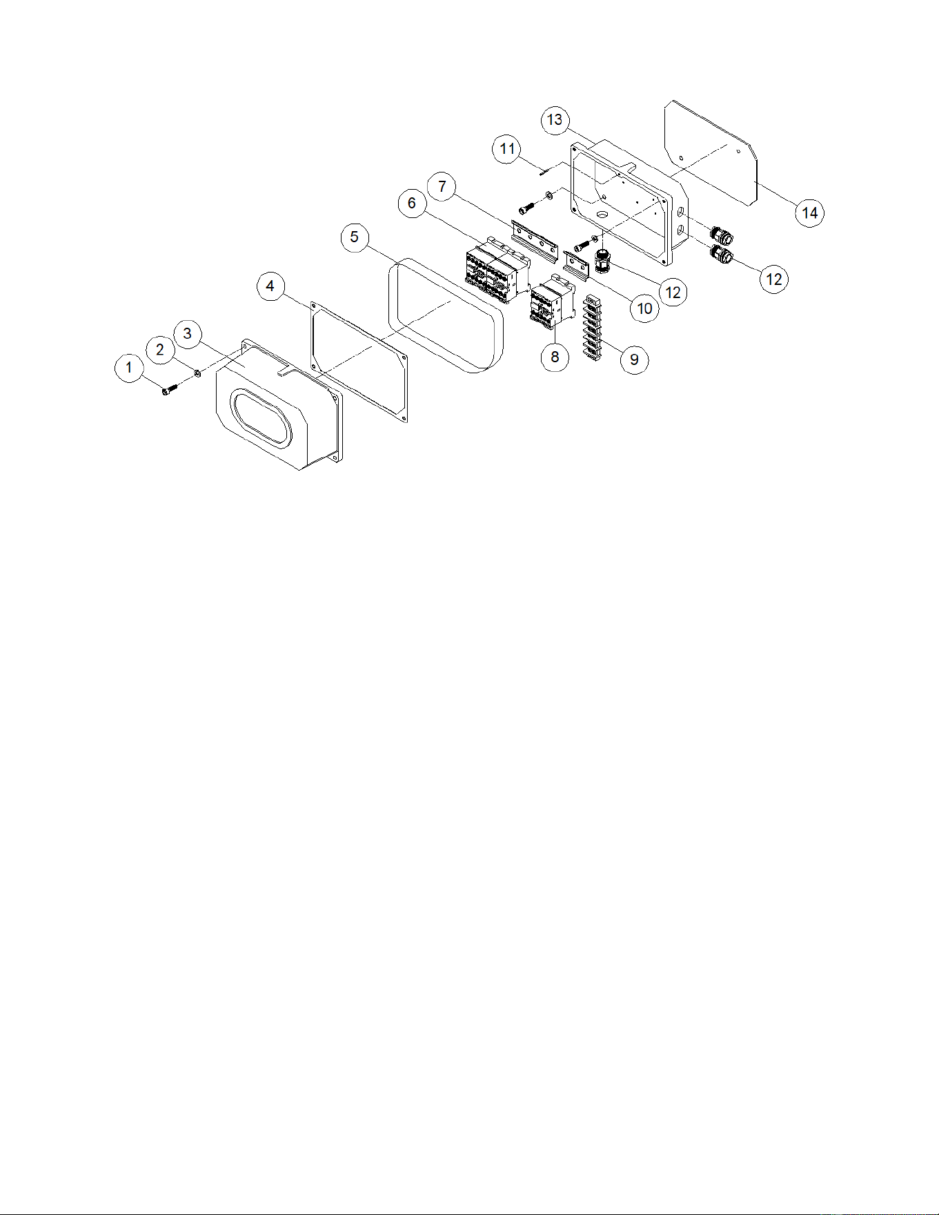
18
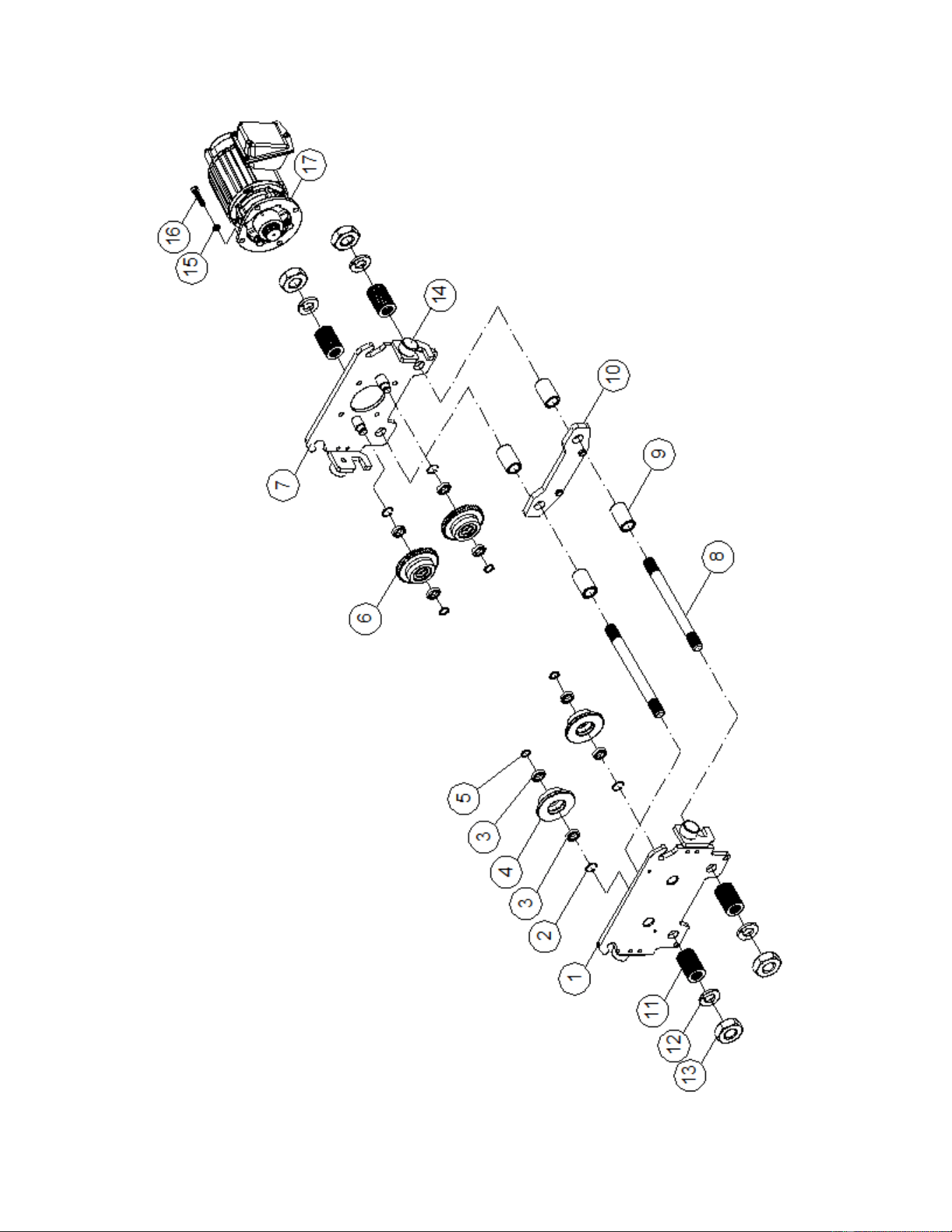
11.3.1 MT050 and MT100 Trolley Electricals – Exploded View
11.3.2 MT050 and MT100 Trolley Electricals – Parts List
Index No. Part No. Description Size Qty
1 ................ TS-1482031 .............. Socket Hd Cap Screw ............................................. M6×1.0×16L .................. 6
2 ................ TS-2361061 .............. Spring Washer ........................................................ M6 ................................. 6
3 ................ MT050-C03 ............... Electric Housing Cover ............................................ ...................................... 1
4 ................ MT050-C04 ............... Gasket ..................................................................... #15 ................................ 1
5 ................ MT050-C05 ............... Rubber Band............................................................ ...................................... 1
6 ................ MT050-C06 ............... Magnetic Contactor 110V ...................................... LC1-D09-F7 .................. 2
7 ................ MT050-C07 ............... Contactor Rail ......................................................... 2PC ............................... 1
8 ................ MT050-C08 ............... Magnetic Contactor 110V ........................................ LC1-D128-F7 ................ 1
9 ................ MT050-C09 ............... Terminal Block ......................................................... ...................................... 1
10 .............. MT050-C10 ............... Contactor Rail ......................................................... 1PC ............................... 1
11 .............. 40317-15 ................... Spring Pin ............................................................... Ø 3×14L ......................... 1
12 .............. MT050-C12 ............... Cable Gland ............................................................ M20 ............................... 3
13 .............. MT050-C13 ............... Electric Housing ....................................................... ...................................... 1
14 .............. MT050-C14 ............... Gasket ..................................................................... #16 ................................ 1
19
11.4.1 MT200 Trolley Frame – Exploded View

20
11.4.2 MT200 Trolley Frame – Parts List
Index No. Part No. Description Size Qty
1 ................ MT200-A01 ............... Electric Frame Assembly ......................................... ...................................... 1
3 ................ BB-6205ZZ ................ Bearing ................................................................... 6205ZZ.......................... 8
4 ................ MT200-A04 ............... Plain Wheel ............................................................. Ø 119×49L ..................... 2
5 ................ F006050 .................... C-Retaining Ring, Ext .............................................. S-25 .............................. 4
6 ................ MT200-A06 ............... Gear Wheel ............................................................. Ø 130×54L ..................... 2
7 ................ MT200-A07 ............... Motor Frame Assembly............................................ ...................................... 1
8 ................ MT200-A08 ............... Stay Bolt ................................................................. 1-1/4"×7UNC×335L ...... 2
9 ................ MT200-A09 ............... Position Tube .......................................................... Ø 48×Ø 34×69L .............. 4
10 .............. MT200-A10 ............... Load Bracket............................................................ ...................................... 1
11 .............. MT200-A11 ............... Spacer Washer ....................................................... Ø 54×Ø 34×1/8" ............ 32
12 .............. MT200-A12 ............... Spring Washer ........................................................ 1-1/4" ............................ 4
13 .............. MT200-A13 ............... Hex. Nut .................................................................. 1-1/4"×7UNC................. 4
14 .............. MT050-A14 ............... Bumper .................................................................... ...................................... 2
15 .............. TS-2361101 .............. Spring Washer ........................................................ M10 ............................... 4
16 .............. TS-1491031 .............. Hex. Head Bolt ...................................................... M10×1.5×25L ................ 4
17 .............. MT200-A17 ............... Motor Assembly......................................3~230V60Hz0.37/0.09kW ............... 1
.................. MT200-A17M ............ Motor Assembly .................................... 3~460V60Hz0.37/0.09kW ............... 1
Extension Kit Accessories for MT200
Part No. Description “E” width, sect. 4.0
MT200-A08AB ........ Includes #8, #9, #11~#13 .............................. 5.94~8.85 in. (151~225mm) .......... OPTIONAL
MT200-A08AC ....... Includes #8, #9, #11~#13 .............................. 8.89~12.2 in. (226~310mm) .......... OPTIONAL
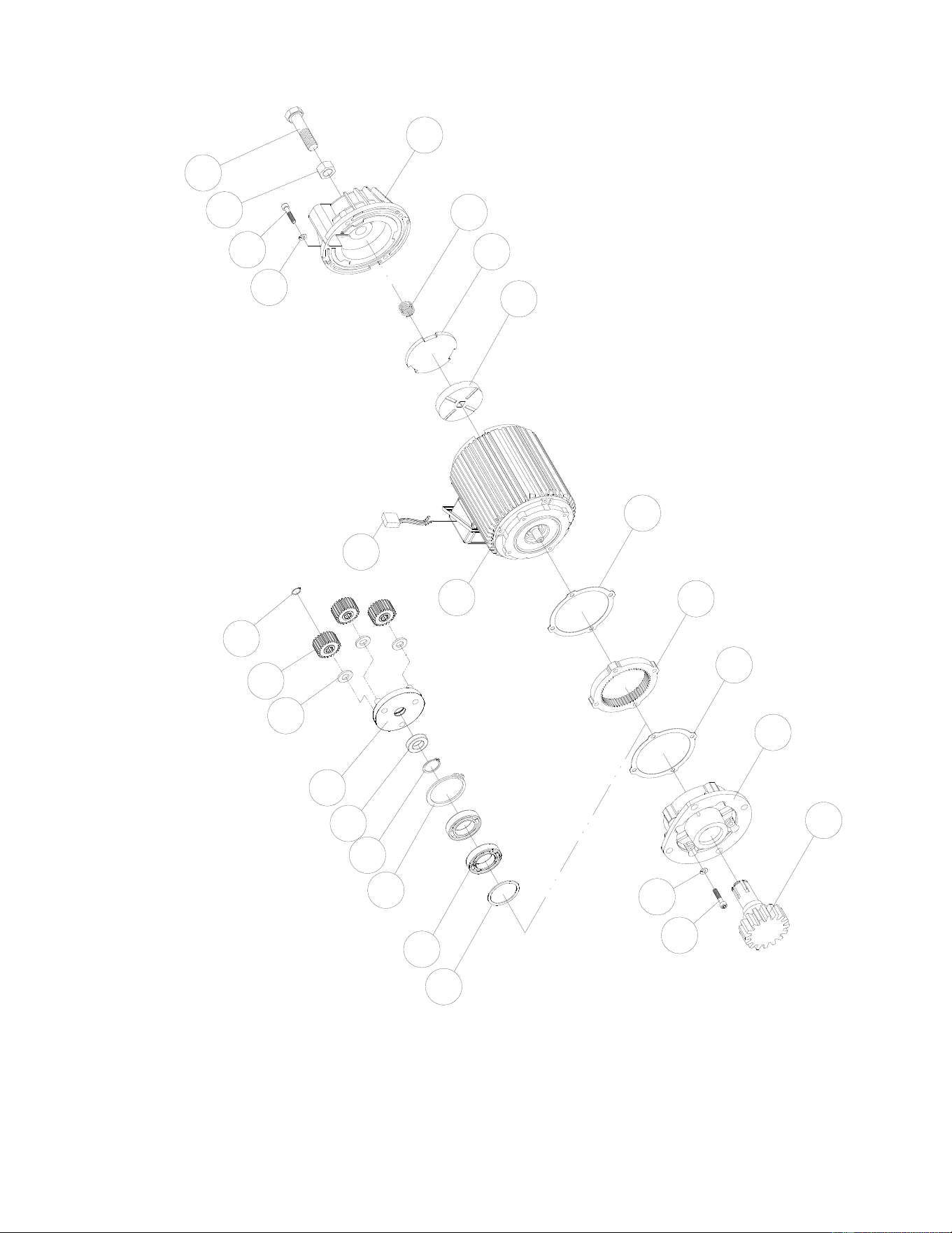
21
11.5.1 MT200 Trolley Motor – Exploded View
23
17
18
11
10
20
19
22
21
1
5
2
3
4
6
13
12
24
8
9
7
19
16
15
14
11

22
11.5.2 MT200 Trolley Motor – Parts List
Index No. Part No. Description Size Qty
1 ................ MT050-B01 ............... Oil Seal ................................................................... Ø 25×Ø 40×6t ................. 1
2 ................ BB-6204Z .................. Bearing ................................................................... 6204Z ............................ 2
3 ................ MT050-B03 ............... Retaining Ring ........................................................ R-47 .............................. 1
4 ................ MT050-B04 ............... Retaining Ring ........................................................ S-20 .............................. 1
5 ................ MT050-B05 ............... Axle Sleeve .............................................................. ...................................... 1
6 ................ MT050-B06 ............... Reducing Gear Frame Ass’y.................................... ...................................... 1
7 ................ MT050-B07 ............... Flat Washer ............................................................ Ø 21×Ø 11×2t ................. 3
8 ................ MT050-B08 ............... Planetary Gear......................................................... ...................................... 3
9 ................ MT050-B09 ............... Retaining Ring ........................................................ S-10 .............................. 3
10 .............. MT050-B10 ............... Hex. Head Bolt ....................................................... M6×1×60L ..................... 4
11 .............. TS-2361061 .............. Spring Washer ........................................................ M6 ................................. 8
12 .............. MT200-B12 ............... Motor Stator Ass’y ................................ 3~230V60Hz0.37/0.09kW ............... 1
.................. MT200-B12M ............ Motor Stator Assembly ..........................3~460V60Hz0.37/0.09kW ............... 1
13 .............. MT050-B13 ............... Rectifier.................................................................... ...................................... 1
14 .............. TS-1482041 .............. Hex. Head Bolt ........................................................ M6×1.0×20L .................. 4
15 .............. TS-1540081 .............. Nut .......................................................................... M12×1.75 ...................... 1
16 .............. TS-1492021 .............. Hex. Head Bolt ....................................................... M12×1.75×30L .............. 1
17 .............. MT200-B17 ............... Transmission Shaft With Pinion ............................... ...................................... 1
18 .............. MT050-B18 ............... Gear Box.................................................................. ...................................... 1
19 .............. MT050-B19 ............... Gear Box Gasket .................................................... ...................................... 2
20 .............. MT050-B20 ............... Internal Ring Gear .................................................. ...................................... 1
21 .............. MT050-B21 ............... Brake Lining Ass’y ................................................... ...................................... 1
22 .............. MT050-B22 ............... Brake Disc ............................................................... ...................................... 1
23 .............. MT050-B23 ............... Brake Spring ............................................................ ...................................... 1
24 .............. MT050-B24 ............... Brake Drum Ass’y .................................................... ...................................... 1
23
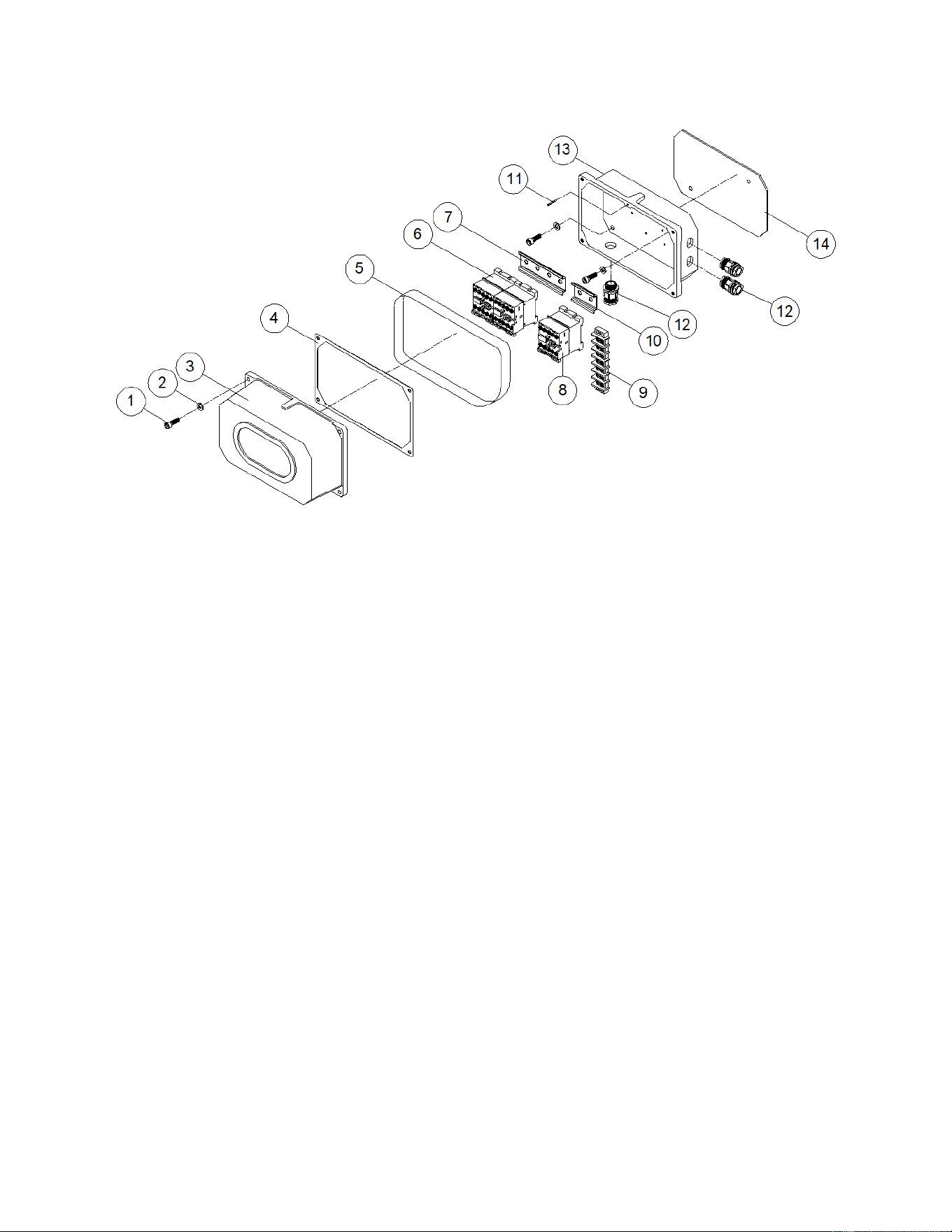
11.6.1 MT200 Trolley Electricals – Exploded View
11.6.2 MT200 Trolley Electricals – Parts List
Index No. Part No. Description Size Qty
1 ................ TS-1503041 .............. Socket Hd Cap Screw ............................................. M6×1.0×16L .................. 6
2 ................ TS-2361061 .............. Spring Washer ........................................................ M6 ................................. 6
3 ................ MT050-C03 ............... Electric Housing Cover ............................................ ...................................... 1
4 ................ MT050-C04 ............... Gasket #15 .............................................................. ...................................... 1
5 ................ MT050-C05 ............... Rubber Band............................................................ ...................................... 1
6 ................ MT050-C06 ............... Magnetic Contactor 110V ....................................... LC1-D09-F7 .................. 2
7 ................ MT050-C07 ............... Contactor Rail ......................................................... 2PC ............................... 1
8 ................ MT050-C08 ............... Magnetic Contactor 110V ........................................ LC1-D128-F7 ................ 1
9 ................ MT050-C09 ............... Terminal Block ......................................................... ...................................... 1
10 .............. MT050-C10 ............... Contactor Rail ......................................................... 1PC ............................... 1
11 .............. MT050-C11 ............... Spring Pin ............................................................... Ø 3×14L ......................... 1
12 .............. MT050-C12 ............... Cable Gland ............................................................ M20 ............................... 3
13 .............. MT050-C13 ............... Electric Housing ....................................................... ...................................... 1
14 .............. MT050-C14 ............... Gasket #16 .............................................................. ...................................... 1
24
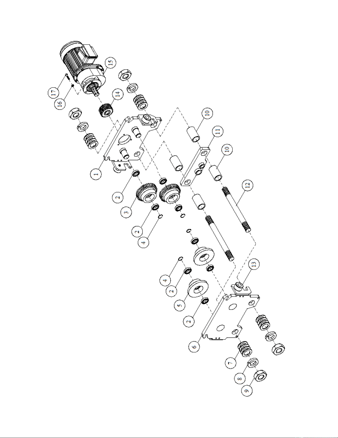
11.7.1 MT300 and MT500 Trolley Frame – Exploded View

25
11.7.2 MT300 and MT500 Trolley Frame – Parts List
Index No. Part No. Description Size Qty
1 ................ MT300-A01 ............... Motor Frame Assembly............................................ ...................................... 1
.................. MT500-A01 ............... ................................................................................. ...................................... 1
2 ................ BB-6207Z .................. Bearing ................................................................... 6207Z ............................ 8
3 ................ MT300-A03 ............... Gear Wheel ............................................................. M3.5×39T×67L.............. 2
4 ................ F006054 .................... C-Retaining Ring, Ext .............................................. S-35 .............................. 4
5 ................ MT300-A05 ............... Plain Wheel ............................................................. Ø 143.5×59L .................. 2
6 ................ MT300-A06 ............... Electric Frame Assembly ......................................... ...................................... 1
.................. MT500-A06 ............... ................................................................................. ...................................... 1
7 ................ MT300-A07 ............... Spacer Washer ....................................................... Ø 60×Ø 40×1/8" ............ 32
.................. MT500-A07 ............... ................................................................................. Ø 60×Ø 47×6.5L ........... 16
8 ................ MT300-A08 ............... Spring Washer ........................................................ 1-1/2" ............................ 4
.................. MT500-A08 ............... ................................................................................. 1-3/4”............................. 4
9 ................ MT300-A09 ............... Hex. Nut .................................................................. 1-1/2"×6UNC................. 4
.................. MT500-A09 ............... ................................................................................. 1-3/4”x5UNC ................. 4
10 .............. MT300-A10 ............... Position Tube .......................................................... Ø 50×Ø 40×83.5L ........... 4
.................. MT500-A10 ............... ................................................................................. Ø 60×Ø 47×83L .............. 4
11 .............. MT300-A11 ............... Load Bracket............................................................ ...................................... 1
.................. MT500-A11 ............... ................................................................................. ...................................... 1
12 .............. MT300-A12 ............... Stay Bolt ................................................................. 1-1/2"×6UNC×390L ...... 2
.................. MT500-A12 ............... ................................................................................. 1-3/4”x5UNCx415L ....... 2
13 .............. MT050-A13 ............... Bumper .................................................................... ...................................... 4
14 .............. MT300-A14 ............... Pinion ...................................................................... M3.5×16T×49L.............. 1
15 .............. MT300-A15 ............... Reducing Gear Motor Assembly .........................3~230V60Hz0.6/0.15Kw .... 1
.................. MT300-A15M ............ Reducing Gear Motor Assembly ......................... 3~460V60Hz0.6/0.15Kw .... 1
16 .............. TS-2361081 .............. Spring Washer ........................................................ M8 ................................. 3
17 .............. TS-1504061 .............. Hex. Bolt .................................................................. M8×1.25×30L ................ 3
Extension Kit Accessories, for MT300 and MT500
Part No. Description “E” width, sect. 4.0
MT300-A12AB ........ Includes #8, #9, #11~#13 .............................. 6.92~9.84 in. (176~250mm) .......... OPTIONAL
MT300-A12AC ....... Includes #8, #9, #11~#13 .............................. 9.88~12.2 in. (251~310mm) .......... OPTIONAL
MT500-A12AB ........ Includes #8, #9, #11~#13 .............................. 6.92~9.84 in. (176~250mm) .......... OPTIONAL
MT500-A12AC ....... Includes #8, #9, #11~#13 .............................. 9.88~12.2 in. (251~310mm) .......... OPTIONAL
26
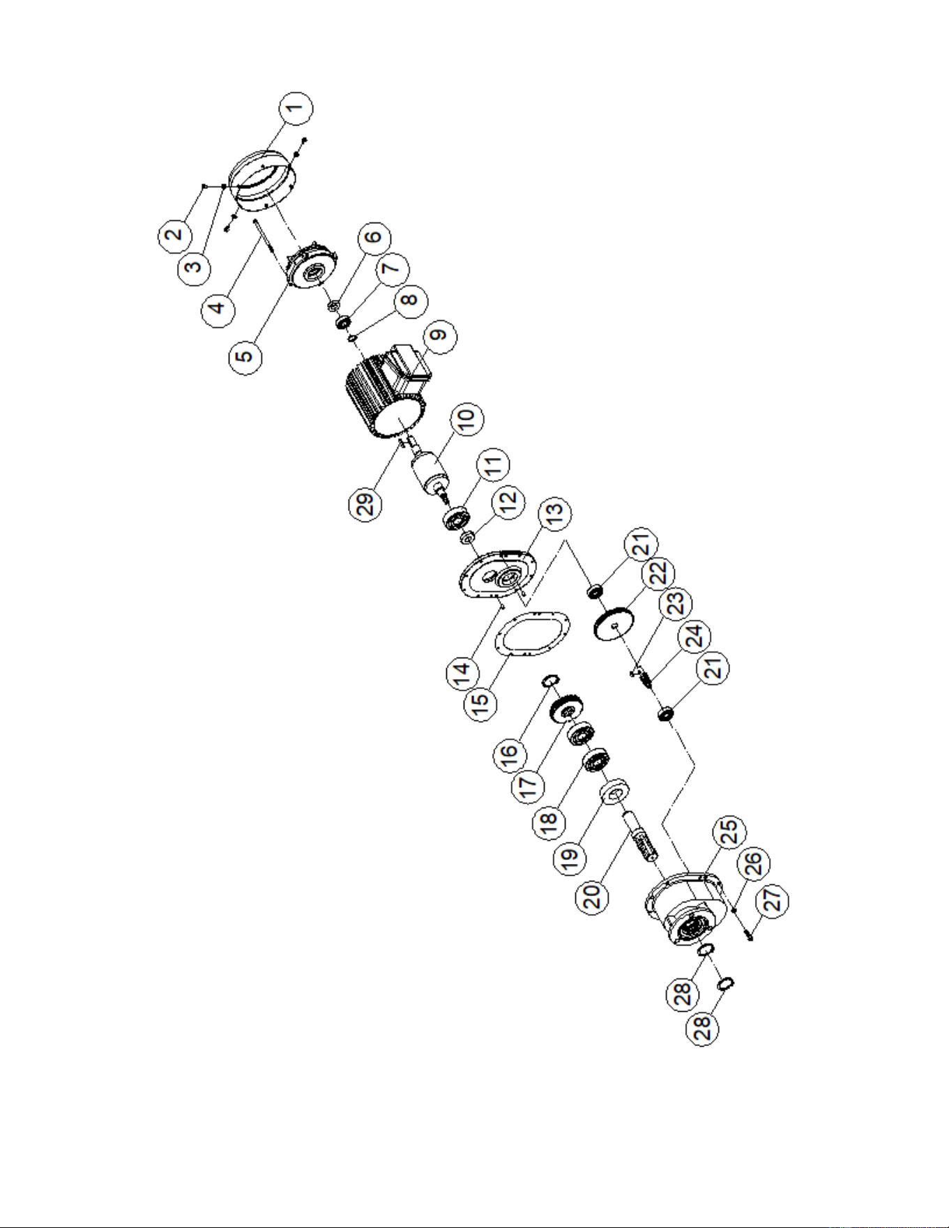
11.8.1 MT300 and MT500 Trolley Motor – Exploded View

27
11.8.2 MT300 and MT500 Trolley Motor – Parts List
Index No. Part No. Description Size Qty
1 ................ MT300-B01 ............... Brake End Cover ..................................................... ...................................... 1
2 ................ F001208 .................... Phillips Pan Hd Mach Screw ................................... M5×0.8×8L .................... 4
3 ................ TS-2361051 .............. Spring Washer ........................................................ M5 ................................. 4
4 ................ MT300-B04 ............... Hex. Bolt ................................................................. M5×0.8×160 .................. 4
5 ................ MT300-B05 ............... Brake Assembly ....................................................... (SBV-YS-071A) ............. 1
6 ................ MT300-B06 ............... Oil Seal ................................................................... Ø 17×Ø 35×8t ................. 1
7 ................ BB-6203ZZ ................ Bearing ................................................................... 6203ZZ.......................... 1
8 ................ F006045 .................... C-Retaining Ring, Ext ............................................. S-17 .............................. 1
9 ................ MT300-B09 ............... Motor Stator Assembly.........................................3~230V60Hz0.6/0.15kw .... 1
.................. MT300-B09M ............ Motor Stator Assembly ...................................... 3~460V60Hz0.6/0.15kw .... 1
10 .............. MT300-B10 ............... Motor Rotor ............................................................. Ø 64×80×228 ................. 1
11 .............. BB-6204ZZ ................ Bearing ................................................................... 6204ZZ.......................... 1
12 .............. MT300-B12 ............... Oil Seal ................................................................... Ø 35×Ø 20×8t ................. 1
13 .............. MT300-B13 ............... Flange ...................................................................... ...................................... 1
14 .............. MT300-B14 ............... Spring Pin ............................................................... Ø 5×16L ......................... 2
15 .............. MT300-B15 ............... Gearbox Gasket....................................................... ...................................... 1
16 .............. F006050 .................... C-Retaining Ring, Ext .............................................. S-25 .............................. 1
17 .............. MT300-B17 ............... 4th Gear .................................................................. M1.75x47T .................... 1
18 .............. BB-6205ZZ ................ Bearing ................................................................... 6205ZZ.......................... 2
19 .............. MT300-B19 ............... Oil Seal ................................................................... Ø 52×Ø 32×11t ............... 1
20 .............. MT300-B20 ............... Transmission Shaft ................................................. Ø 32×147.5 .................... 1
21 .............. BB-6203ZZ ................ Bearing ................................................................... 6203ZZ.......................... 2
22 .............. MT300-B22 ............... 2nd Gear ................................................................. M1.25×71T .................... 1
23 .............. 3K00227 .................... Key, Dbl Rd Hd ........................................................ t6×6×15 ......................... 1
24 .............. MT300-B24 ............... 3rd Gear .................................................................. M1.75×13T .................... 1
25 .............. MT300-B25 ............... Gearbox A................................................................ ...................................... 1
26 .............. TS-2361061 .............. Spring Washer ........................................................ M6 ................................. 8
27 .............. TS-1503041 .............. Socket Hd Cap Screw ............................................. M6×1.0×16 .................... 8
28 .............. F006052 .................... C-Retaining Ring, Ext .............................................. S-30 .............................. 2
29 .............. KS050525 ................. Key, Dbl Rd Hd ........................................................ t5×5×25 ......................... 1
28
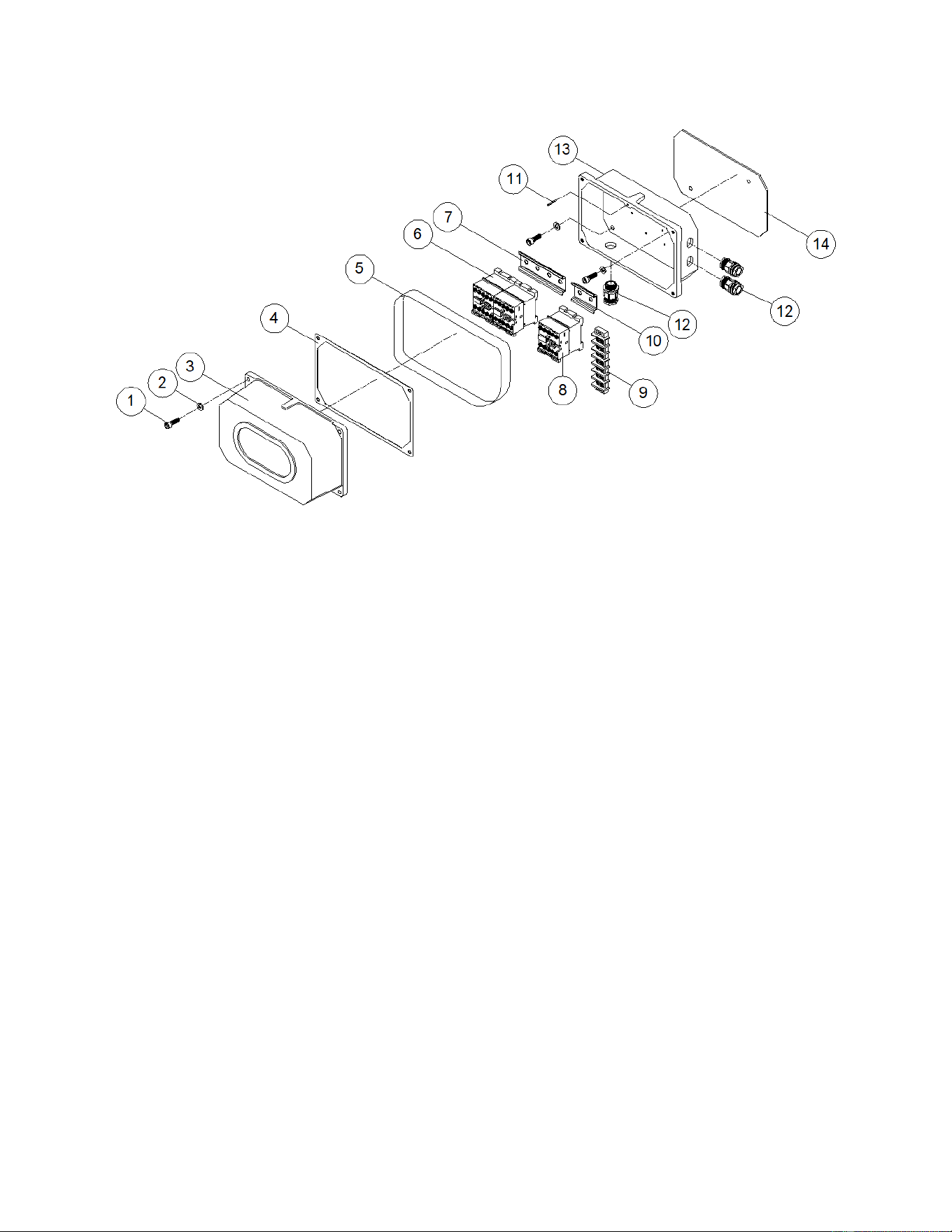
11.9.1 MT300 and MT500 Trolley Electricals – Exploded View
11.9.2 MT300 and MT500 Trolley Electricals – Parts List
Index No. Part No. Description Size Qty
1 ................ TS-1482031 .............. Hex. Recess Bolt .................................................... M6×1.0×16L .................. 6
2 ................ TS-2361061 .............. Spring Washer ........................................................ M6 ................................. 6
3 ................ MT050-C03 ............... Electric Housing Cover ............................................ ...................................... 1
4 ................ MT050-C04 ............... Gasket #15 .............................................................. ...................................... 1
5 ................ MT050-C05 ............... Rubber Band............................................................ ...................................... 1
6 ................ MT050-C06 ............... Magnetic Contactor 110V ...................................... LC1-D09-F7 ................. 2
7 ................ MT050-C07 ............... Contactor Rail ......................................................... 2PC ............................... 1
8 ................ MT050-C08 ............... Magnetic Contactor 110V ........................................ LC1-D128-F7 ................ 1
9 ................ MT050-C09 ............... Terminal Block ......................................................... ...................................... 1
10 .............. MT050-C10 ............... Contactor Rail ......................................................... 1PC ............................... 1
11 .............. MT050-C11 ............... Spring Pin ............................................................... Ø 3×14L ......................... 1
12 .............. MT050-C12 ............... Cable Gland ............................................................ M20 ............................... 3
13 .............. MT050-C13 ............... Electric Housing ....................................................... ...................................... 1
14 .............. MT050-C14 ............... Gasket #16 .............................................................. ...................................... 1
29
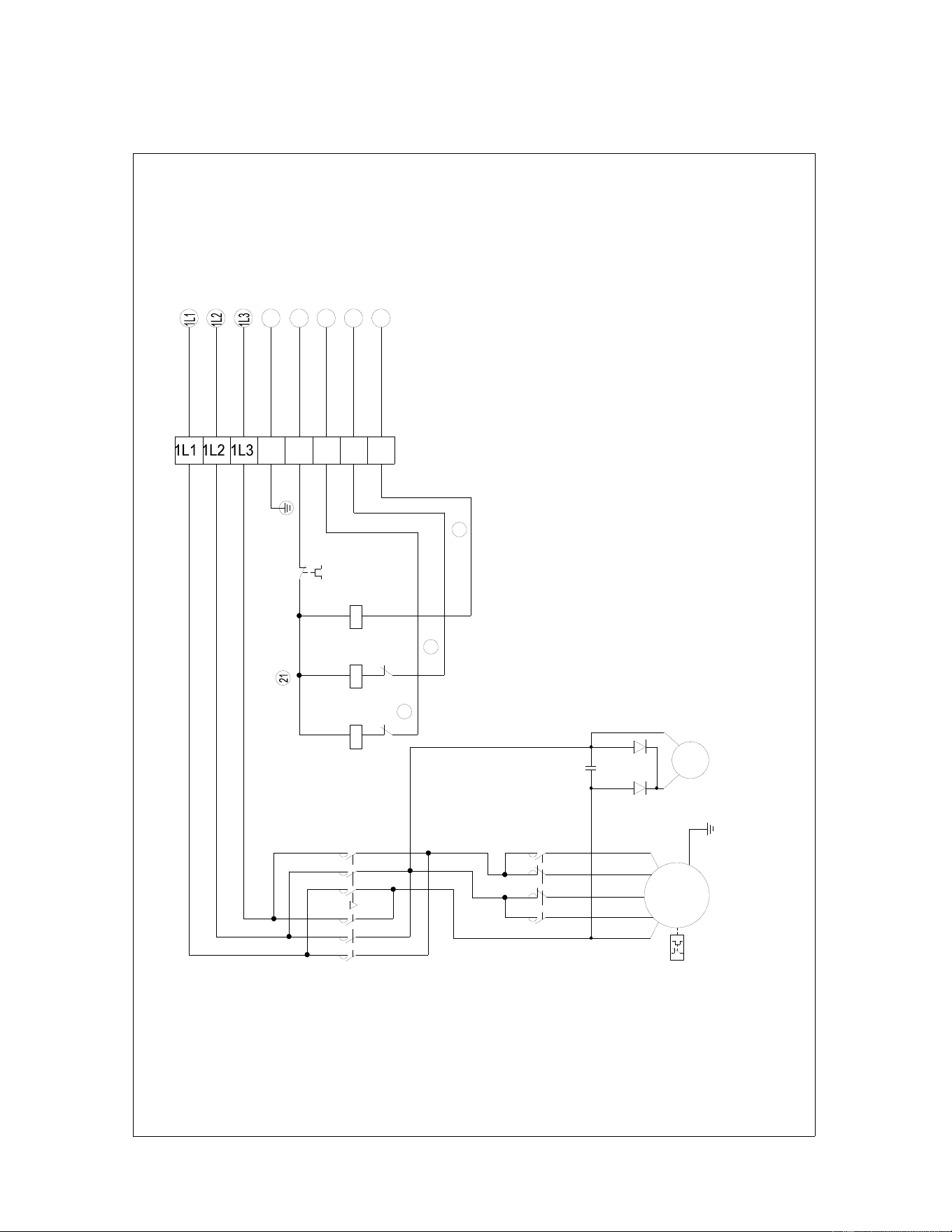
12.0 Electrical connections
12.1 MT Trolley wiring
SF20000968-21101
MT050~MT500
KM6
R1
R3
1
3
M
TRAVERSING
E
MOTOR
2/8P
BRAKE
BC
FR3
M1
M4
M6
M5
M3
2
KM7
R2
R4
4
C
KM5
2
4
2
6
3
1
5
2
6
4
1
3
5
KM5
KM6
3
4
KM7
FR3
2 43
E
1E
2
4
3
1
E
M2
KM6
KM5

30
13.0 Warranty and Service
JET warrants every product it sells against manufacturers’ defects. If one of our tools needs service or repair, please
contact Technical Service by calling 1-800-274-6846, 8AM to 5PM CST, Monday through Friday.
Warranty Period
The general warranty lasts for the time period specified in the literature included with your product or on the official
JET branded website.
JET products carry a limited warranty which varies in duration based upon the product. (See chart below)
Accessories carry a limited warranty of one year from the date of receipt.
Consumable items are defined as expendable parts or accessories expected to become inoperable within a
reasonable amount of use and are covered by a 90 day limited warranty against manufacturer’s defects.
Who is Covered
This warranty covers only the initial purchaser of the product from the date of delivery.
What is Covered
This warranty covers any defects in workmanship or materials subject to the limitations stated below. This warranty
does not cover failures due directly or indirectly to misuse, abuse, negligence or accidents, normal wear-and-tear,
improper repair, alterations or lack of maintenance. JET woodworking machinery is designed to be used with Wood.
Use of these machines in the processing of metal, plastics, or other materials outside recommended guidelines may
void the warranty. The exceptions are acrylics and other natural items that are made specifically for wood turning.
Warranty Limitations
Woodworking products with a Five Year Warranty that are used for commercial or industrial purposes default to a
Two Year Warranty. Please contact Technical Service at 1-800-274-6846 for further clarification.
How to Get Technical Support
Please contact Technical Service by calling 1-800-274-6846. Please note that you will be asked to provide proof
of initial purchase when calling. If a product requires further inspection, the Technical Service representative will
explain and assist with any additional action needed. JET has Authorized Service Centers located throughout the
United States. For the name of an Authorized Service Center in your area call 1-800-274-6846 or use the Service
Center Locator on the JET website.
More Information
JET is constantly adding new products. For complete, up-to-date product information, check with your local distributor
or visit the JET website.
How State Law Applies
This warranty gives you specific legal rights, subject to applicable state law.
Limitations on This Warranty
JET LIMITS ALL IMPLIED WARRANTIES TO THE PERIOD OF THE LIMITED WARRANTY FOR EACH PRODUCT.
EXCEPT AS STATED HEREIN, ANY IMPLIED WARRANTIES OF MERCHANTABILITY AND FITNESS FOR A
PARTICULAR PURPOSE ARE EXCLUDED. SOME STATES DO NOT ALLOW LIMITATIONS ON HOW LONG AN
IMPLIED WARRANTY LASTS, SO THE ABOVE LIMITATION MAY NOT APPLY TO YOU.
JET SHALL IN NO EVENT BE LIABLE FOR DEATH, INJURIES TO PERSONS OR PROPERTY, OR FOR
INCIDENTAL, CONTINGENT, SPECIAL, OR CONSEQUENTIAL DAMAGES ARISING FROM THE USE OF OUR
PRODUCTS. SOME STATES DO NOT ALLOW THE EXCLUSION OR LIMITATION OF INCIDENTAL OR
CONSEQUENTIAL DAMAGES, SO THE ABOVE LIMITATION OR EXCLUSION MAY NOT APPLY TO YOU.
JET sells through distributors only. The specifications listed in JET printed materials and on official JET website are
given as general information and are not binding. JET reserves the right to effect at any time, without prior notice,
those alterations to parts, fittings, and accessory equipment which they may deem necessary for any reason
whatsoever. JET
®
branded products are not sold in Canada by JPW Industries, Inc.
Product Listing with Warranty Period
90 Days – Parts; Consumable items
1 Year – Motors; Machine Accessories
2 Year – Metalworking Machinery; Electric Hoists, Electric Hoist Accessories; Woodworking Machinery used
for industrial or commercial purposes; Air Tools
5 Year – Woodworking Machinery
Limited Lifetime – JET Parallel clamps; VOLT Series Electric Hoists; Manual Hoists; Manual Hoist
Accessories; Shop Tools; Warehouse & Dock products; Hand Tools
NOTE: JET is a division of JPW Industries, Inc. References in this document to JET also apply to JPW Industries,
Inc., or any of its successors in interest to the JET brand.

31