
Instructions on displays of the panel in the standby
mode
B2010 Bluetooth Operating Manual(240408_V1.4)
:
After the power-on initialization is completed, check the panel (press the confirm button, with one time for one of the
followings) which displays the followings circularly.
Display of clock → display of ambient temperature → display of power supply voltage → display of
gear/temperature setting → display of shell temperature → display of the failure code in case of a failure
Instructions on button
operating
Standby mode
Up button: temperature / gear
Power button: short press to power on, and the panel displays ON.
+
Down button: temperature / gear -
Confirm button: cyclically switch the displays.
Setting button: set parameter.
Power on mode
Power button: long press to power off, and the panel displays OFF.
Up button: temperature / gear +
Down button: temperature / gear -
Confirm button: cyclically switch the displays.
Setting button: set parameter.
Instructions on remote control
code matching
Standby mode
Press the setting button and up button at the same time to enter the remote control code matching interface, and the panel
displays -PE-; long press the ON/OFF button on the remote control for code matching. After the code matching is successfully
finished, exit automatically or press the power button again to exit; it will automatically exit in case of no press for 20s.

Manual/constant-temperature/a
utomatic start/stop mode
switching operation instructions
Standby mode/power
on mode
When selecting manual and constant-temperature modes in parameter settings, quick switching can only be performed
between manual and constant-temperature modes.
When selecting the automatic start/stop mode in the parameter settings, quick switching can only be performed between
manual and automatic start/stop modes.
The steps to switch between different modes are as follows:
1. Press and hold the up/down key simultaneously to switch between constant-temperature mode or automatic start/stop mode.
The interface will display "27 ℃" and flash. Press again to switch to manual mode, and the interface will display "P-01"
(default manual mode).
2. When the machine is powered on, press and hold the ON key on the remote controller for 3 seconds to cycle between
manual or constant-temperature modes or manual and automatic start/stop modes. Each switch must be separated by more than
3 seconds before switching again.
Instructions on manual oil
pumping
Standby mode
Press the setting button and the down button at the same time to enter the manual oil pumping interface which displays the
time “020” for example. Press the setting button to set the number, press the up button to add the pumping time, and press the
down button to reduce the pumping time (manual range of up to 999 seconds). Short press the confirm button to start/stop
pumping, while pressing the power button to exit, or the pumping will automatically exit in case of no press for 20s.
Instructions on temperature
display switching
Standby mode/power
on mode
Degrees Celsius is displayed by default, such as "27℃". In the power-on mode, long press the Up button for 3 seconds to
switch the display of Degrees Fahrenheit, and the interface displays "27 ℉";
At this time, any content related to temperature display will be switched to Fahrenheit display;
Ventilation Mode Operation
Instructions
Standby Mode
Long press the Settings button and Power button for 3 seconds. There will be "ON" indicator flashing on the interface,
indicating that the ventilation mode is activated. Press the up/down button to switch between different levels. For example, if it
displays "-P2-" (Level 1-5). Long press the Power button for 3 seconds to exit the ventilation mode, and the "OFF" indicator
will flash on the interface.
Instructions on parameter
setting
(Long press the setting button
in the standby mode to enter the
parameter setting interface)
Clock setting
The initial time display is "00:00" and the first blank flashes. Press the up/down button to set the number. After the clock
setting is finished, short press the confirm button to enter the next blank. The subsequent numbers are set in sequence, and
short press the setting button to enter the next item.
Timed start-up setting
The initial time display is "00:00" and the first blank flashes. Press the up/down button to set the number. After the clock
setting is finished, short press the confirm button to enter the next blank. The subsequent numbers are set in sequence, and
short press the setting button to enter the next item.

Timed shutdown
setting
The initial time display is "00:00" and the first blank flashes. Press the up/down button to set the number. After the clock
setting is finished, short press the confirm button to enter the next blank. The subsequent numbers are set in sequence, and
short press the setting button to enter the next item.
Password input
Initially, it displays “----” and the first blank flashes. Press the up/down button to change the number, and then press the
confirm button to confirm it to enter the next blank. The subsequent numbers are set in sequence, and finally press the confirm
button to enter the next setting when the password is correct.
Display of P1H2 on
the parameter setting
interface
The first "P" indicates the manual mode, the first "t" indicates the constant-temperature mode, and the first "A" indicates the
automatic start/stop mode, which can be cycled. After setting, briefly press the confirmation key to enter the next parameter.
It displays “1” on the second blank for 12V accessories, Press the up/down button to switch to 24V accessories/AU
accessories(Automatic voltage matching). Display "2"/"A" . can be switched cyclically. After the setting, short press the
confirm button to enter the next setting.
It displays “H” on the third blank for 5KW, while “L”/“U” for 2KW/8KW. Press the up/down button to switch to 2KW/8KW.
can be switched cyclically. After the setting, short press the confirm button to enter the next setting.
It displays “2” on the fourth blank for the 22mL pump, “8” for the 28mL pump and “1” for the 16ML pump. Press the up
button to switch to the 28mL pump, while the down button to 16mL pump. The three types can be switched cyclically. After
the setting, short press the power button to exit, or the setting will automatically exit in case of no press for 20s.
Auto-start
temperature setting
Select the automatic start/stop mode, press the power button to enter the startup temperature setting interface, and the initial
display is "ON: 25";
Press the up/down key to adjust the flashing position, briefly press the confirmation key to enter the next parameter, set the
values in sequence, and then briefly press the power button to exit the setting (range: 15 ℃ - 35 ℃); after returning to the main
interface, press the up/down button to modify the automatic shutdown temperature;
Note: Automatic shutdown occurs when the ambient temperature is higher than the shutdown temperature; after automatic
shutdown, when the ambient temperature is lower than the starting temperature, it will start automatically.
Note: After all parameter settings are finished, please press the power button to confirm and save the settings before exiting. No settings will be
saved in case of automatic exit after timeout.
Bluetooth Connection
Instructions
Power On/Standby
Mode
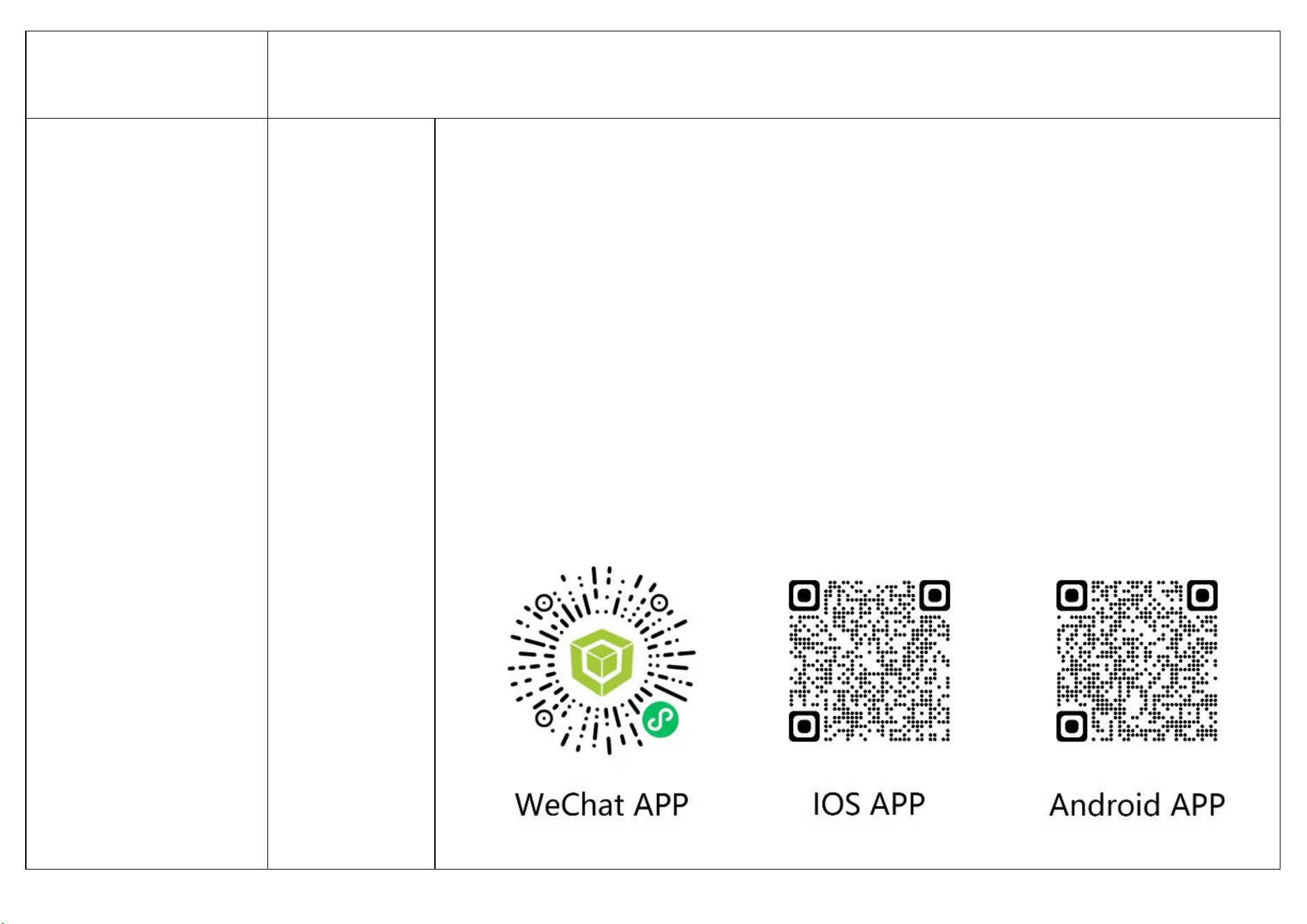
Open the mobile app or WeChat program and navigate to the QR code binding interface.
1. Click on the “Scan QR code” option and scan the corresponding QR code on the panel. If the connection is
successful, it will redirect to the device control interface and prompt that the connection is successful, displaying
specific working parameters.
2.Click on the “Auto-Search Device” option to start automatic searching. If the device is successfully connected, it will
redirect to the device control interface and prompt that the connection is successful, displaying specific working
parameters.
(To disconnect the device, go to the personal center, click on “Device management”, and follow the steps to unbind the
device. Alternatively, long press the Settings button and the Confirm button on the panel for 3 seconds, and the
software will prompt that the Bluetooth is disconnected. For detailed Bluetooth operation instructions, please refer to
the software's personal center.)
Instructions on screen off
Standby mode
The screen will completely turn off after no press for more than 5 minutes.
Power on mode
The screen will turn off after no press for more than 5 minutes If the screen is off, there will be a breathing light prompt and it
will display “ ”. Press any button to wake up the screen.
Instructions on failures and how to
deal with them
Under voltage
E-01
The voltage is too low: for 24V, lower than 18V, and for 12V, lower than 10V.
Over voltage
E-02
The voltage is too high: for 24V, higher than 32V, and for 12V, higher than 17V.
Spark plug failure
E-03/F1
Short circuit of spark plug
E-03/F2
Open circuit of spark plug
Oil pump failure
E-04/F1
Short circuit of oil pump
E-04/F2
Open circuit of oil pump
Overheating
E-05
The shell temperature exceeds 260℃. Check whether the air inlet and outlet are blocked.
Motor failure
E-06/F1
Short circuit of fan
E-06/F2
Open circuit of fan
E-06/F3
Fan speed not recognized by Hall sensor
Disconnection
E-07
Check whether the communication cable or plug between the power button and the controller is open or virtually connected.
Flame failure
E-08
Check whether there is air or wax blockage in the oil circuit, resulting in poor oil supply.
Sensor failure
E-09/F1
Short circuit of case temperature sensor
E-09/F2
Open circuit of case temperature sensor
Ignition failure
E-10
In case of two times of ignition failure, check the reasons such as blocked oil circuit, not smooth oil intake, stuck oil pump or blocked
volatile net due to oil problems.
Failures in ambient
temperature sensors
E-11
Ambient temperature sensors are open or short-circuited.
Controller overheating
E-12
The temperature of the controller exceeds 100
℃
. Check whether the air inlet and outlet are blocked, or whether the ECU is damaged.
This device complies with part 15 of the FCC Rules. Operation is subject to the following two conditions:
(1) This device may not cause harmful interference, and
(2) this device must accept any interference received, including interference that may cause undesired operation.
Any Changes or modifications not expressly approved by the party responsible for compliance could void the user's authority to
operate the equipment.
Note: This equipment has been tested and found to comply with the limits for a Class B digital device, pursuant to part 15 of the
FCC Rules. These limits are designed to provide reasonable protection against harmful interference in a residential installation.
This equipment generates uses and can radiate radio frequency energy and, if not installed and used in accordance with the
instructions, may cause harmful interference to radio communications. However, there is no guarantee that interference will not
occur in a particular installation. If this equipment does cause harmful interference to radio or television reception, which can be
determined by turning the equipment off and on, the user is encouraged to try to correct the interference by one or more of the
following measures:
-Reorient or relocate the receiving antenna.
-Increase the separation between the equipment and receiver.
-Connect the equipment into an outlet on a circuit different from that to which the receiver is connected.
-Consult the dealer or an experienced radio/TV technician for help.
This equipment complies with FCC radiation exposure limits set forth for an uncontrolled environment. This equipment should
be installed and operated with minimum distance 20cm between the radiator & your body.