
MANUFACTURER'S LIMITED WARRANTY
(APPLICABLE ONLY IN THE UNITED STATES AND CANADA)
WARRANTY REGISTRATION:
To register your Jackson Dishmachine’s warranty go to jacksonwws.com/warranty or call 1-888-800-5672. Failure to
register the Dishmachine will void the warranty.
ONE YEAR LIMITED PARTS AND LABOR WARRANTY
For a period of one (1) year from date of original installation of a new Jackson Dishmachine (but in no event to exceed
eighteen (18) months from date of shipment from Jackson’s factory), Jackson WWS, Inc. (Jackson) will repair or replace,
at its discretion, any original part that proves defective in materials or workmanship at the time the Dishmachine was
purchased; provided that (i) the Dishmachine has not been altered, (ii) the Dishmachine has been properly installed,
maintained, and operated under normal use conditions and in accordance with the applicable installation, operation and
service manual available on the Jackson website, and (iii) a warranty claim is reported to a Jackson Authorized Service
Agency within the warranty period. This warranty includes replacement with Jackson specied genuine replacement
parts, purchased directly from a Jackson Authorized Parts Distributor or Service Agency. Use of generic replacement
parts may create a hazard and shall void this warranty.
THIS WARRANTY DOES NOT APPLY OUTSIDE THE UNITED STATES AND CANADA.
Jackson will pay the labor to repair or replace a defective original part as a part of the warranty, provided that a Jackson
Authorized Service Agency performs the labor. Any repair or replacement work by anyone other than a Jackson
Authorized Service Agency is the sole responsibility of the purchaser. Labor coverage is limited to regular hourly rates;
Jackson will not pay overtime premiums or emergency service charges.
Accessory components (such as table limit switches, pressure regulators, and drain water tempering kits) that are not
installed by Jackson at the factory and are shipped with the Dishmachine carry only a (1) one-year parts warranty. Labor
to repair or replace these components is not included in the warranty or covered by Jackson. Booster heaters not
manufactured by Jackson are not covered by this warranty but are warranted by their respective manufacturers.
This warranty is void if any defect or failure is a direct result from shipping, handling, re, water, accident, alteration,
modication, misuse, abuse, ood, acts of God, burglary, casualty, attempted repair by unauthorized persons, use of
replacement parts not authorized by Jackson, improper installation, installation not in accordance with local electrical and
plumbing codes, if the serial number has been removed or altered, if the Dishmachine is used for any purpose other than
originally intended, or if the equipment is installed for residential use.
Jackson does not authorize any other entity or person, including, without limitation, any entity or person who deals in
Jackson Dishmachines, to change this warranty or create any other obligation in connection with Jackson Dishmachines.
TRAVEL LIMITATIONS:
Jackson limits warranty travel time to the customer site within 50 miles of the Jackson authorized service agent’s oce
and during regular business hours. Jackson will not pay for travel time and mileage that exceeds these limits, or any fees
such as those for air or boat travel without prior authorization.
REPLACEMENT PARTS WARRANTY:
For a period of (90) ninety days from the date of installation by a Jackson Authorized Service Agency (but in no event to
exceed (180) one-hundred-eighty days from the date of purchase from a Jackson Authorized Parts Distributor or Service
Agency), Jackson will repair or replace, at its discretion, any Jackson genuine replacement parts that prove defective
in materials or workmanship at the time the replacement parts were installed. This warranty does not include paying
the labor to repair or replace the replacement part. This warranty is subject to all conditions, exclusions and limitations
applicable to the Dishmachine.

MANUFACTURER'S LIMITED WARRANTY (CONT.)
(APPLICABLE ONLY IN THE UNITED STATES AND CANADA)
PRODUCT CHANGES:
Jackson reserves the right to make changes in design and specication of any component of the Dishmachine as
engineering or necessity requires.
DISCLAIMER OF WARRANTIES:
THERE ARE NO WARRANTIES, EXPRESSED OR IMPLIED, INCLUDING, WITHOUT LIMITATION, ANY IMPLIED
WARRANTY OF FITNESS FOR A PARTICULAR PURPOSE OR MERCHANTABILITY, THAT ARE NOT SET FORTH
HEREIN, OR THAT EXTEND BEYOND THE DURATION HEREOF.
LIMITATION OF REMEDIES AND LIABILITIES:
YOUR SOLE AND EXCLUSIVE REMEDY UNDER THIS LIMITED WARRANTY SHALL BE PRODUCT REPAIR OR
REPLACEMENT AS PROVIDED HEREIN.
UNDER NO CIRCUMSTANCES WILL JACKSON BE LIABLE FOR ANY INCIDENTAL OR CONSEQUENTIAL
DAMAGES, OR FOR DAMAGES IN THE NATURE OF PENALTIES. JACKSON’S LIABILITY ON ANY CLAIM OF ANY
KIND WITH RESPECT TO THE GOODS OR SERVICES COVERED HEREUNDER SHALL IN NO CASE EXCEED THE
PRICE OF THE GOODS OR SERVICES OR PART THEREOF WHICH GIVES RISE TO THE CLAIM.
ITEMS NOT COVERED:
THIS WARRANTY DOES NOT COVER (1) ADJUSTMENTS INCLUDING, BUT NOT LIMITED TO, TIMER CAMS,
THERMOSTATS, DOORS, TANK HEATER ADJUSTMENTS OR CLUTCHES; (2) AIR FREIGHT OR OVERNIGHT
FREIGHT; (3) ANY AMOUNT EXCEEDING ORIGINAL PURCHASE PRICE; (4) CLEANING OF DRAIN VALVES,
GAS LINES, RINSE/WASH NOZZLES, STRAINERS, SCREENS, OR SPRAY PIPES; (5) CLEANING OR DELIMING
OF THE DISHMACHINE OR ANY COMPONENT INCLUDING, BUT NOT LIMITED TO, WASH ARMS, RINSE
ARMS AND STRAINERS; (6) CONDITIONS CAUSED BY THE USE OF INCORRECT (NON-COMMERCIAL)
GRADE DETERGENTS; (7) CORROSION FROM CHEMICALS DISPENSED IN EXCESS OF RECOMMENDED
CONCENTRATIONS; (8) COSMETIC DAMAGE, INCLUDING BUT NOT LIMITED TO, SCRATCHES, DENTS, CHIPS,
AND OTHER DAMAGE TO THE DISHMACHINE FINISHES, UNLESS SUCH DAMAGE RESULTS FROM DEFECTS IN
MATERIALS AND WORKMANSHIP AND IS REPORTED TO JACKSON WITHIN (30) THIRTY DAYS FROM THE DATE
OF INSTALLATION; (9) DAMAGE CAUSED BY LABOR DISPUTE; (10) DAMAGES RESULTING FROM IMPROPER
CONNECTION TO UTILITY SERVICE; (11) DAMAGES RESULTING FROM WATER CONDITIONS, INADEQUATE OR
EXCESSIVE WATER PRESSURE, ACCIDENTS, ALTERATIONS, IMPROPER USE, ABUSE, HANDLING, OVERLOADS,
TAMPERING, IMPROPER INSTALLATION OR FAILURE TO FOLLOW MAINTENANCE AND OPERATING
PROCEDURES; (12) DISCOLORATION, RUST OR OXIDATION OF SURFACES RESULTING FROM CAUSTIC
OR CORROSIVE ENVIRONMENTS, INCLUDING, BUT NOT LIMITED TO, HIGH SALT CONCENTRATIONS, HIGH
MOISTURE OR HUMIDITY, OR EXPOSURE TO CHEMICALS; (13) ELECTRIC BOOSTERS, FEED LINES, FLEX HOSE,
FUSES, GARBAGE DISPOSALS, OR GAS PILOTS; (14) EXCESSIVE LIME, MINERAL, OR ALKALINE BUILDUP; (15)
EXPENSES DUE TO DISCONNECTION, DELIVERY, RETURN AND REINSTALLATION; (16) FAILURE OF ELECTRICAL
COMPONENTS DUE TO CONNECTION OF CHEMICAL DISPENSING EQUIPMENT INSTALLED BY OTHERS; (17)
FAILURE OF FACILITY WATER HEATER TO MAKE TEMPERATURE; (18) FAILURE TO MAINTAIN WATER HARDNESS
LOWER THAN 3.0 GRAINS, PH BETWEEN 7.0 AND 8.5 AND TOTAL DISSOLVED SOLIDS BELOW 250 PPM; (19)
FAILURE TO COMPLY WITH LOCAL ELECTRICAL BUILDING CODES; (20) LEAKS OR DAMAGE RESULTING FROM
SUCH LEAKS CAUSED BY THE INSTALLER, INCLUDING THOSE AT MACHINE TABLE CONNECTIONS, OR BY
CONNECTION OF CHEMICAL DISPENSING EQUIPMENT INSTALLED BY OTHERS; (21) OPENING OR CLOSING OF
UTILITY SUPPLY VALVES OR SWITCHING OF ELECTRICAL SUPPLY CURRENT; (22) PERFORMANCE OF REGULAR
MAINTENANCE AND CLEANING AS OUTLINED IN THE OPERATOR’S GUIDE; (23) REMOVAL OR REINSTALLATION
OF INACCESSIBLE DISHMACHINES OR BUILT-IN FIXTURES THAT INTERFERE WITH SERVICING, REMOVAL OR
REPLACEMENT OF THE DISHMACHINE; (24) REPLACEMENT WEAR ITEMS INCLUDING, BUT NOT LIMITED TO,
CURTAINS, DRAIN BALLS, DOOR GUIDES, GASKETS, O-RINGS, SEALS, SQUEEZE TUBES, AND BEARINGS; (25)
RESIDENTIAL USE; (26) USE WITH UTILITY SERVICE OTHER THAN THAT DESIGNATED ON THE RATING PLATE.
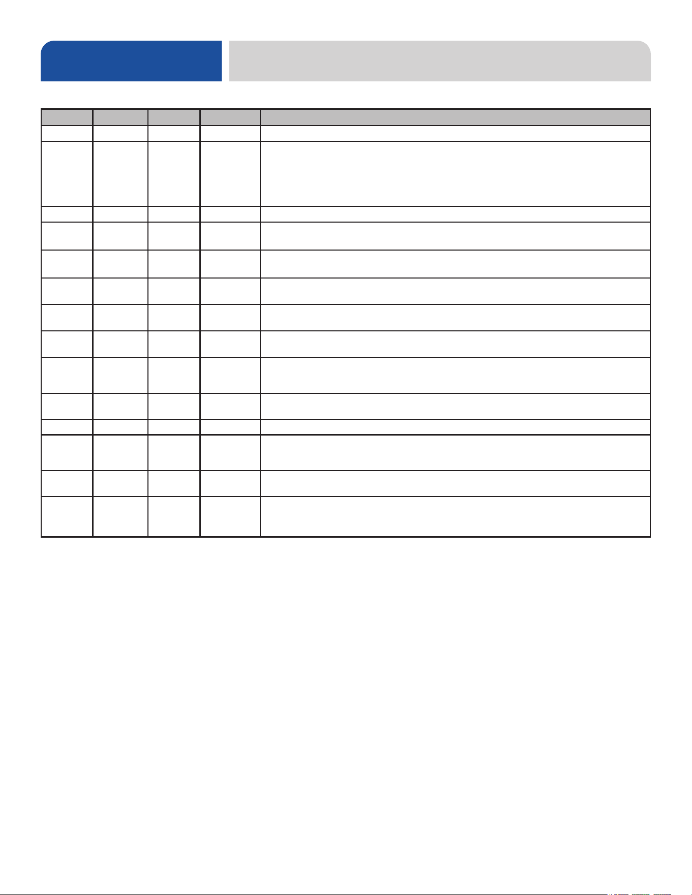
Revision Date Made by Process Details
A 5-25-18 JH 8566 Initial release of the manual.
B 2-25-19 JH
8585
8619
8630
8648
8682
Updated pgs. 2–3. Added note about hot water heaters to pg. 6. Updated references to
adjustable outputs on pg. 11. Added programming instructions and fault codes to pgs. 21–25.
Updated pg. 29 to show panel and membrane together. Corrected P/N of item #20 on pg. 38.
Updated pg. 40. Updated SEER System, pgs. 47-48. Updated drain water tempering kit and
added link to instructions on pg. 51. Updated schematic.
C 4-24-19 JH 19-553 Updated schematic.
D 6-17-20 JH
8664
8709
Revised Programming Chemical Feeder Pumps section. Updated Chemical Feeder Pumps
parts pages. Added wash heater gasket to pg. 51. Updated SEER System pages.
E 11-18-20 JH N/A
Revised drain line size. Updated dimensional drawings. Added F12 in Fault Codes section.
Adjusted quantities and added door spring on pg. 38. Updated Item #3 on pg. 41.
F 2-6-21 JH 8810
Changed Priming Chemical Feeder Pumps section. Added spacer and updated blower wheel
P/N on SEER System pages.
G 7-13-21 JH
8808
20-931
Updated Fault Codes section. Changed pressure regulator on SEER unit. Updated rinse
plumbing assembly.
H 12-22-21 JH N/A
Updated water consumption per Energy Star 3.0 report. Revised Electrical Requirements
section. Added description of Energy Saver Mode.
J 5-5-22 JH
22-1201
22-1202
Removed water hardness test strip. Updated Chemical Feeder Pumps section with black dot
roller and corrected squeeze tube P/Ns. Corrected Rinse Tank section to show plumbing.
Added gasket to SEER System page.
K 6-17-22 JH 8888
Removed universal timer. New electrical panel, chemical feeder pumps, and door interlock.
Updated schematic.
L 7-8-22 JH N/A Changed program number in Programming section.
M 12-2-22 JH
8901
22-1445
22-1503
Updated inlet plumbing hose. Changed chemical tubing. Updated peri-pumps to black
components. Added door handle bolts and washers. Updated schematic.
N 6-6-23 JH 8905
Added all adjustable settings to Programming section. Updated I/O module P/N to kit. Updated
to new door with new start switch. Added relay to door interlock. Updated schematic.
P 12-6-23 JH N/A
Changed wording in Priming Chemical Pumps section to direct user to Programming section to
adjust chemicals. Updated rinse injector P/Ns. Added serial number cuto and earlier manual
link to SEER System section. Updated schematic.
REVISION HISTORY

i
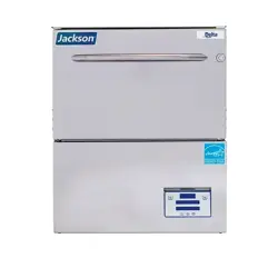
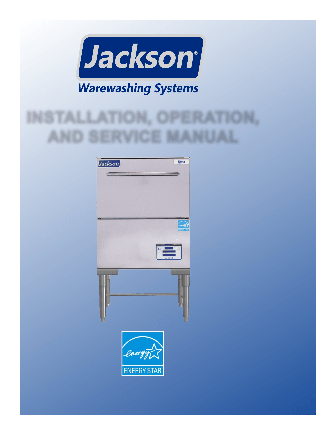
Delta HT-E-SEER-S
Short Stand
Glasswasher dishmachine; high-temperature, hot-water
sanitizing, with a booster tank and detergent
and rinse-aid chemical feeder pumps.
Equipped with Steam Elimination and
Energy Recovery (SEER) system.
6" stand clearance allows
cleaning beneath the machine.
The manufacturer provides
technical support for all of
the dishmachines detailed
in this manual. We strongly
recommend that you refer to
this manual before making a
call to our technical support
sta. Please have this manual
open when you call so that our
sta can refer you, if necessary,
to the proper page. Technical
support is not available on
holidays.
Contact technical support toll
free at 1-888-800-5672.
Technical support is available
for service personnel only.
NOMENCLATURE
Delta HT-E-SEER-T
Tall Stand
Glasswasher dishmachine; high-temperature, hot-water
sanitizing, with a booster tank and detergent
and rinse-aid chemical feeder pumps.
Equipped with Steam Elimination and
Energy Recovery (SEER) system.
14" stand allows storage of
chemicals under the machine.

ii
TABLE OF CONTENTS
GUIDES
Symbols ............................................................................................................................................ 1
Abbreviations & Acronyms ............................................................................................................... 1
SPECIFICATIONS
Dimensions - SEER-S ...................................................................................................................... 2
Dimensions - SEER-T ...................................................................................................................... 3
Operating Parameters ...................................................................................................................... 4
Electrical Requirements ................................................................................................................... 5
INSTRUCTIONS
Installation Instructions ..................................................................................................................... 6
Inspection......................................................................................................................... 6
Unpacking ........................................................................................................................ 6
Plumbing .......................................................................................................................... 6
Water Supply Connections .............................................................................................. 6
Pressure Regulator .......................................................................................................... 7
Shock Absorber ............................................................................................................... 7
Connecting the Drain Line ............................................................................................... 7
Plumbing Check ............................................................................................................... 7
Electrical Power Connections .......................................................................................... 8
Voltage Check .................................................................................................................. 8
Surrounding Area ............................................................................................................. 8
Temperature Setpoints ..................................................................................................... 8
Leveling............................................................................................................................ 8
Chemical Connections ..................................................................................................... 9
Priming Chemical Feeder Pumps .................................................................................. 10
Operating Instructions .................................................................................................................... 11
Preparation .....................................................................................................................11
Power Up ........................................................................................................................11
Filling the Wash Tub .......................................................................................................11
Ware Preparation ........................................................................................................... 12
Washing a Rack of Ware ............................................................................................... 12
Operational Inspection ................................................................................................... 14
Shutdown & Cleaning .................................................................................................... 14
Deliming ......................................................................................................................... 16
Detergent Control........................................................................................................... 17
Energy Saver Mode ....................................................................................................... 17

iii
TABLE OF CONTENTS
MAINTENANCE
Preventative Maintenance .............................................................................................................. 18
TROUBLESHOOTING
Programming .................................................................................................................................. 20
Fault Codes .................................................................................................................................... 22
Troubleshooting .............................................................................................................................. 25
PARTS
Terminal Block Box ......................................................................................................................... 27
Control Kick Panel .......................................................................................................................... 28
Electrical Panel ............................................................................................................................... 29
Chemical Feeder Pump Assembly ................................................................................................. 31
Chemical Feeder Pumps ................................................................................................................ 33
Door ................................................................................................................................................ 34
Door Interlock ................................................................................................................................. 36
Miscellaneous Door Components .................................................................................................. 37
Wash & Motor ................................................................................................................................. 38
Rinse Manifold ................................................................................................................................ 40
Plumbing ........................................................................................................................................ 41
Rinse Plumbing .............................................................................................................................. 43
Scale Prevention System ............................................................................................................... 45
Rinse Tank ...................................................................................................................................... 46
SEER System ................................................................................................................................. 48
Tub & Frame ................................................................................................................................... 50
Miscellaneous Parts ....................................................................................................................... 52
SCHEMATICS
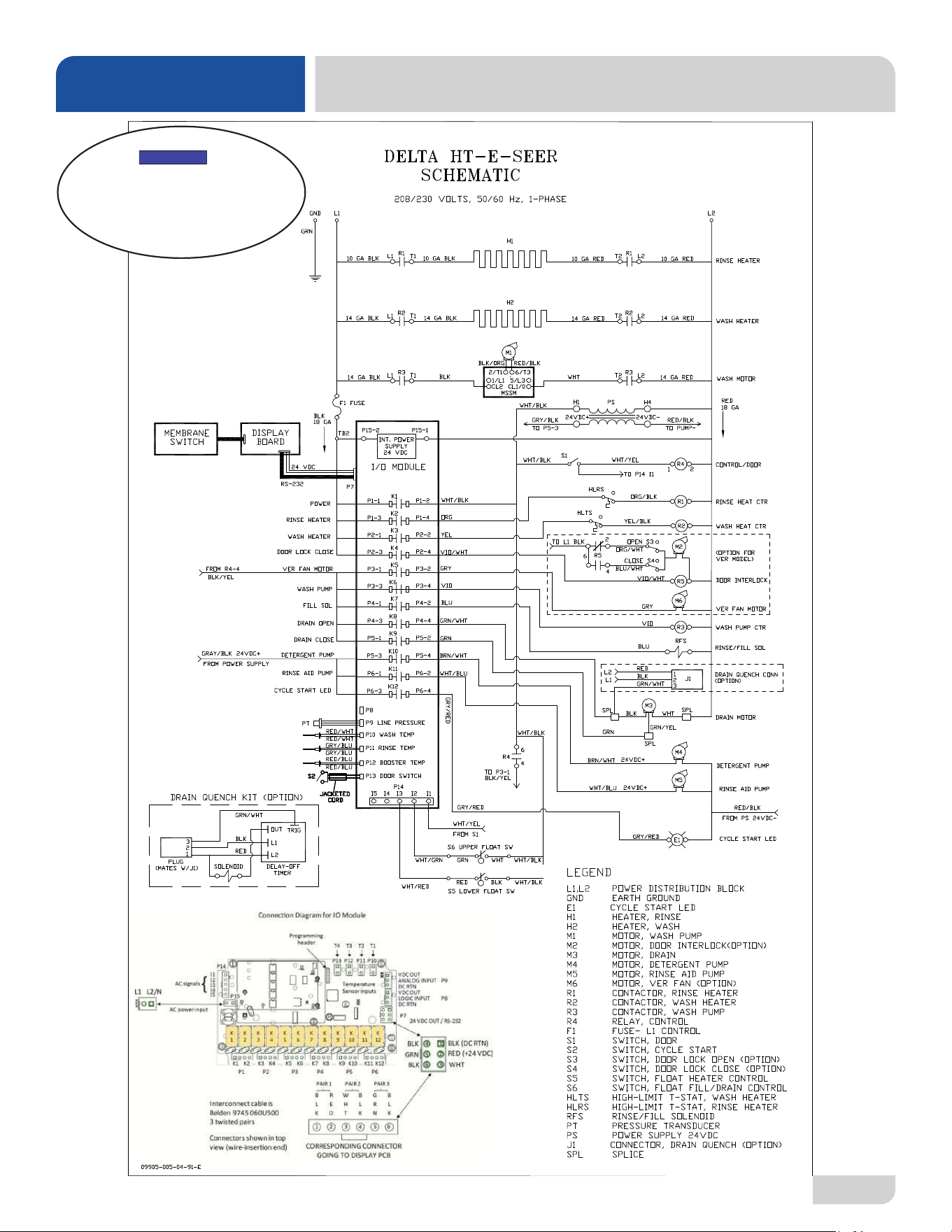
208/230 V, 50/60 Hz, 1 Phase ....................................................................................................... 53
1
07610-004-54-86-P
GUIDES
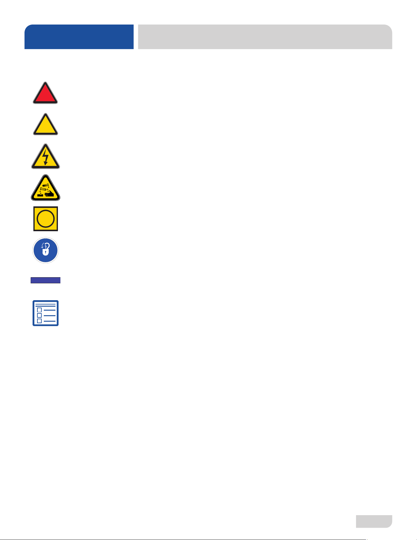
SYMBOLS
ABBREVIATIONS & ACRONYMS
!
CAUTION
!
WARNING
NOTICE
- Risk of Injury to Personnel
- Risk of Damage to Equipment
- Risk of Electrical Shock
- Lockout Electrical Power
- Reference Data Plate
- Important Note
i
- Caustic Chemicals
- Instructions Hyperlink
ANSI - American National Standards Institute
GHT - Garden Hose Thread
GPG - Grains per Gallon
GPM - Gallons per Minute
HP - Horse Power
Hz - Hertz
ID - Inside Diameter
kW - Kilowatts
MCA - Minimum Circuit Ampacity
MOP - Maximum Overcurrent Protection
NFPA - National Fire Protection Association
NPT - National Pipe Thread
OD - Outside Diameter
PRV - Pressure Regulating Valve
PSI - Pounds per Square Inch
V - Volts
07610-004-54-86-P
2
SPECIFICATIONS
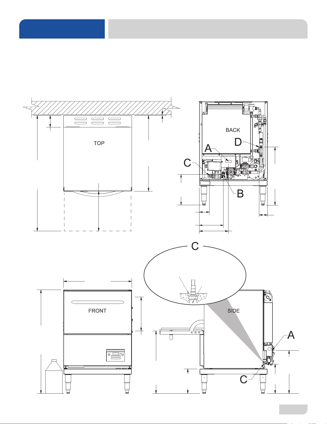
DIMENSIONS - SEER-S
14 7/8
[378 mm]
10
[254 mm]
8 1/4
[210 mm]
20
[508 mm]
36 1/4
[921 mm]
21 7/8
[556 mm]
LEGEND
A - Electrical Connection
B - Water Inlet (with 6' Hose)
(3/4" Male GHT, connect to true
1/2" ID line, 40-90 °F)
C - Drain Connection
(5/8" ID, install into MIN
1 1/2" Drain with Air-gap)
D - Chemical Port
26 7/8
[692 mm]
1/4
[7 mm]
40 7/8
[1037 mm]
4 3/8
[110 mm]
12 [304 mm]
CLEARANCE
3
[76 mm]
14 [356 mm]
DOOR OPEN
24 1/4
[615 mm]
*Back and side views shown with back panel removed.
*
3 5/8
[91 mm]
10 1/4
[261 mm]
8 1/2
[216 mm]
10 3/8
[264 mm]
All dimensions from the floor
can be increased 1” using the
machine’s adjustable feet.
Install Machine
Drain Hose into
1 1/2 [38 mm]
MIN Floor Drain
or Sink
Do NOT install
Drain Hose to
“bottom” of Floor
Drain or Sink.
This can cause
splashback.
*
3
07610-004-54-86-P
SPECIFICATIONS
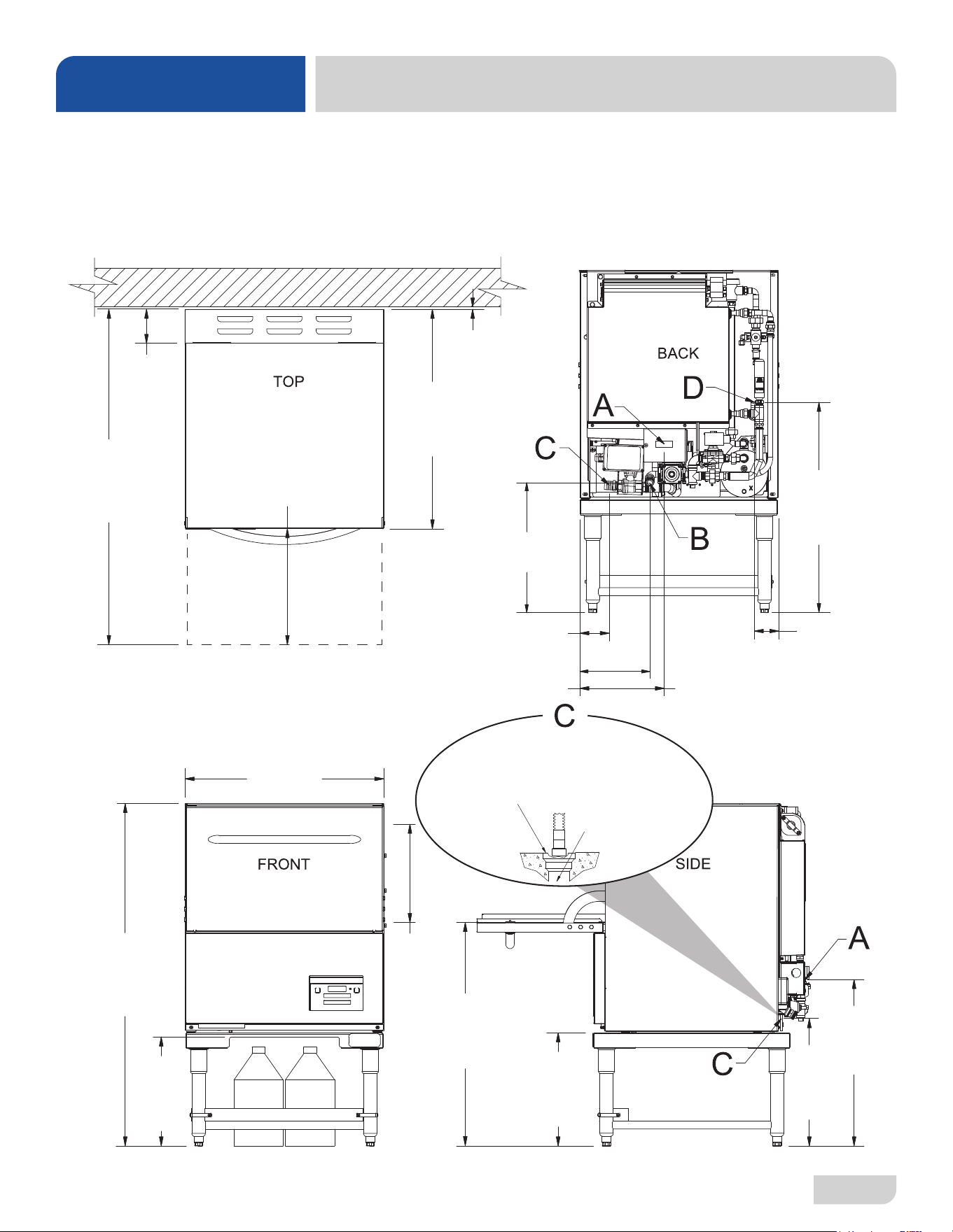
DIMENSIONS - SEER-T
3
[76 mm]
3 5/8
[91 mm]
10 1/4
[261 mm]
14 [356 mm]
DOOR OPEN
24 1/4
[615 mm]
20 3/8
[518mm]
15 1/2
[393 mm]
13 3/4
[349 mm]
25 1/2
[648 mm]
41 3/4
[1059 mm]
27 3/8
[695 mm]
26 7/8
[692 mm]
1/4
[7 mm]
40 7/8
[1037 mm]
4 3/8
[110 mm]
12 [304 mm]
CLEARANCE
13 1/4
[337 mm]
8 1/2
[216 mm]
15 7/8
[402 mm]
*Back and side views shown with back panel removed.
*
LEGEND
A - Electrical Connection
B - Water Inlet (with 6' Hose)
(3/4" Male GHT, connect to true
1/2" ID line, 40-90 °F)
C - Drain Connection
(5/8" ID, install into MIN
1 1/2" Drain with Air-gap)
D - Chemical Port
All dimensions from the floor
can be increased 1” using the
machine’s adjustable feet.
*
Install Machine
Drain Hose into
1 1/2 [38 mm]
MIN Floor Drain
or Sink
Do NOT install
Drain Hose to
“bottom” of Floor
Drain or Sink.
This can cause
splashback.

07610-004-54-86-P
4
SPECIFICATIONS
OPERATING PARAMETERS
Delta HT-E-SEER
Operating Capacity:
Racks per Hour 24 (20)*
Dishes per Hour 600
Glasses per Hour 864
Tank Capacity (Gallons):
Wash Tank 3
Rinse Tank 1.66
Always refer to the machine data plate for specic electrical and water
requirements. The material provided on this page is for reference only and
is subject to change without notice.
Cycle Times (Seconds):
Water Temperatures (°F):
Minimum Wash Temperature 155
Minimum Rinse Temperature 180
Minimum Incoming Water Temperature 40
Maximum Incoming Water Temperature 90
Other Water Requirements:
Water Flow Pressure (PSI) 10
Flow Rate Minimum (GPM) 4.0
Water Line Size (NPT) 3/4" Male GHT
Connect to true 1/2" ID Line
Drain Line Size (NPT) 5/8" ID
Connect to MIN 1 1/2" Drain with
Air-gap
Gallons per Hour (GPH) 14.4 (12.0)**
Gallons per Rack (GPR) 0.60
*Racks per hour calculated with NSF suggested load time of :30 for
front-opening dishmachines.
**Gallons per hour calculated with NSF suggested load time of :30
for front-opening dishmachines.
NOTICE
i
Incoming water is from a
"cold" water line.
Normal
Wash 80
Rinse 9
Dwell 11
SEER 45
Total 145
Heavy
Wash 148
Rinse 9
Dwell 11
SEER 45
Total 213
Extra Heavy
Wash 248
Rinse 9
Dwell 11
SEER 45
Total 313
5
07610-004-54-86-P
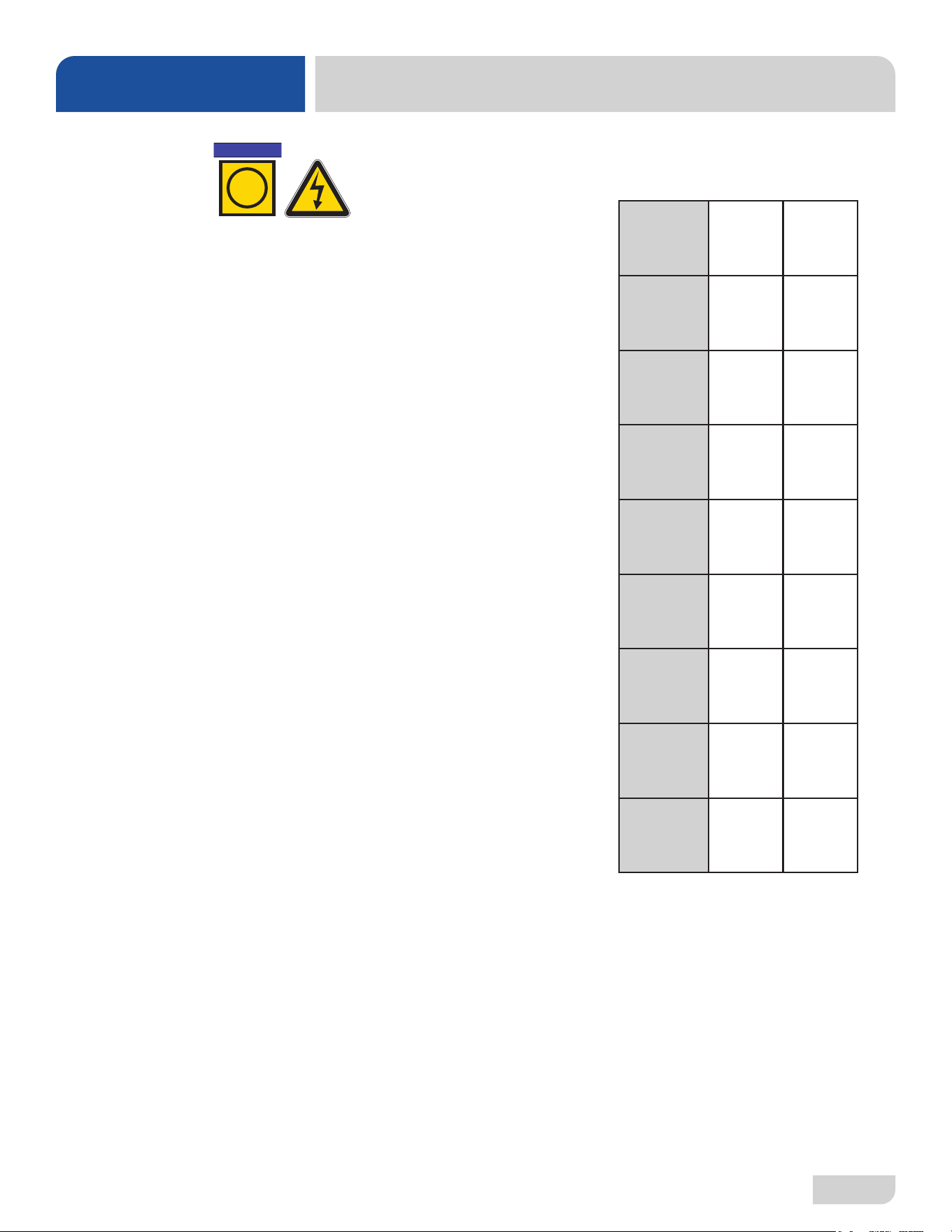
ELECTRICAL REQUIREMENTS
SPECIFICATIONS
*The Delta
®
HT-E-SEER is designed so heaters never run simultaneously. Total Load is based on higher of the two loads.
All electrical ratings provided in this manual are for reference
only. Always refer to the machine data plate to get exact electrical
information for this machine. All electrical work performed on
machines should be done in accordance with applicable local,
state, territorial, and national codes. Work should only be
performed by qualied electricians and authorized service agents.
Amperage loads for motors and heaters are indicated on the
machine data plate.
The electrical congurations are as follows:
Available Electrical Characteristics:
• 208 V, 60 Hz, Single-phase
• 230 V, 60 Hz, Single-phase
Available Wash Motors:
• 3/4 HP
Available Wash Tank Heaters:
• 3.3 kW (208 V)/4.0 kW (230 V)
Available Rinse Tank Heaters:
• 4.1 kW (208 V)/5.2 kW (230 V)
Delta HT-E-SEER
Electrical Characteristics
VOLTS 208 230
PHASE 1 1
FREQ 60 60
WASH
MOTOR
AMPS
6.6 A 6.6 A
WASH
HEATER
AMPS
15.7 A 17.4 A
RINSE
HEATER
AMPS
19.7 A 22.6 A
TOTAL
LOAD
26.3 A* 29.2 A*
MCA 27.9 A 30.8 A
MOP 30 A 35 A
NOTICE
i
07610-004-54-86-P
6
INSTRUCTIONS
INSTALLATION
WATER SUPPLY
CONNECTIONS:
WATER HARDNESS
HIGHER THAN 3 GPG
Before installing the machine, check packaging and machine for damage. Damaged
packaging might be an indication of damage to the machine. If there is any type of
damage to both packaging and unit, do not throw away the packaging. The machine
has been inspected at the factory before shipping and is expected to arrive in new,
undamaged condition. However, rough handling by carriers or others might result in
damage to the machine while in transit. If this occurs, do not return the machine to
the manufacturer. Instead, contact the carrier and ask them to send a representative
to the site to inspect the damage and request that an inspection report be completed.
Contact the carrier within 48 hours of receiving the machine as well as the dealer that
sold you the machine.
The machine should be unpacked and removed from the pallet before installing. Open
the front door and remove all materials from inside. Once unpacked, verify there are no
missing parts. If a part is missing, contact the manufacturer immediately.
All plumbing connections must be made to adhere to local, state, territorial, and
national codes. The installing plumber is responsible for ensuring the incoming
water lines are ushed of debris before connecting to the machine. Note that chips
and materials from cutting processes can become lodged in the solenoid valves
and prevent them from opening or closing. Any valves that are found to be fouled
or defective because of foreign matter left in the water line, and any subsequent
damage, are not the responsibility of the manufacturer.
See the Dimensions page and reference item "B" for water inlet connection location.
The manufacturer does NOT endorse "Tankless On-demand" water heaters
for use with their dishmachines. The manufacturer DOES endorse, and highly
recommends, the standard "Tank" style water heaters, sized to properly handle the
water heating requirements of the facility.
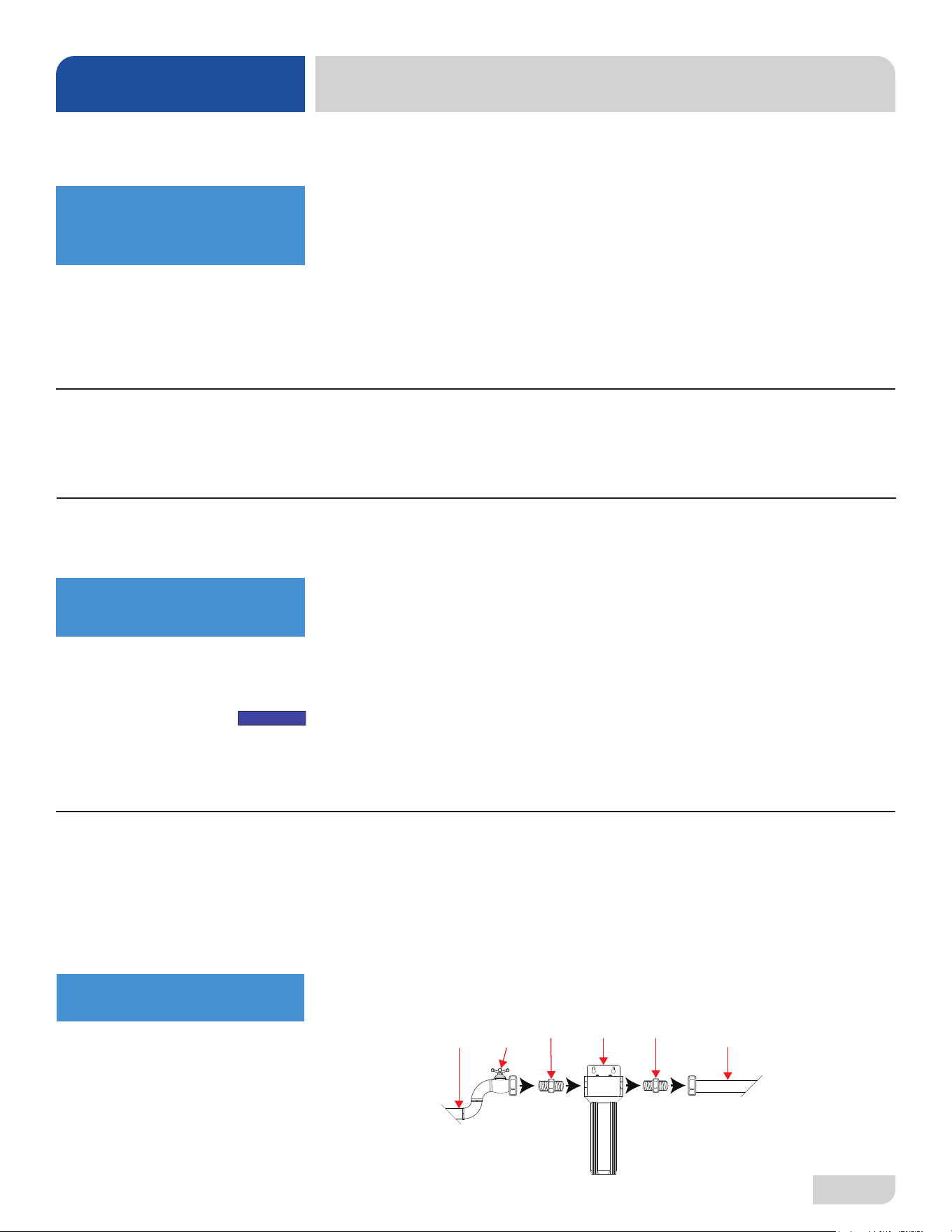
A water hardness test must be performed. If water hardness is higher than 3 GPG and
a water softener is not being used, install the optional Scale Prevention System (SPS)
into the water line between the facility water line and the machine water line (installed
at the factory). See the Scale Prevention System page for more information on the
SPS. Observe proper inlet/outlet water directions. A water shut-o valve should be
installed before installing the SPS to allow access for service. The water supply must
be capable of a minimum of 10 PSI “ow” pressure at the recommended temperature
indicated on the data plate.
INSPECTION
Do not throw away
packaging if damage is
evident!
UNPACKING
PLUMBING
A water hardness test
must be performed.
The plumber must ush
the incoming water line!
Shut-off
Valve
Adapter AdapterSPS Machine
Water Line
Facility
Water Line
* *
*Adapters needed will vary.
Example
NOTICE
7
07610-004-54-86-P
If water hardness tests at 3 GPG or lower, connect the machine water line (installed
at the factory) to the facility water line. A water shut-o valve should be installed in
the water line between the facility supply and the machine to allow access for service.
The water supply line must be capable of a minimum of 10 PSI “ow” pressure at the
recommended temperature indicated on the data plate.
The Delta HT-E-SEER has a pressure regulating valve (PRV) installed at the
factory to accommodate areas where water pressure uctuates or is higher than the
recommended pressure. This machine operates at 10 PSI ow pressure. Take care
not to confuse static pressure with ow pressure: static pressure is line pressure in a
“no ow” condition (all valves and services are closed); ow pressure is the pressure
in the ll line when the valve is opened during the cycle.
A shock absober comes standard on the Delta HT-E-SEER. This prevents water
hammer or hydraulic shock—induced by the solenoid valve as it operates—from
causing damage to the equipment.
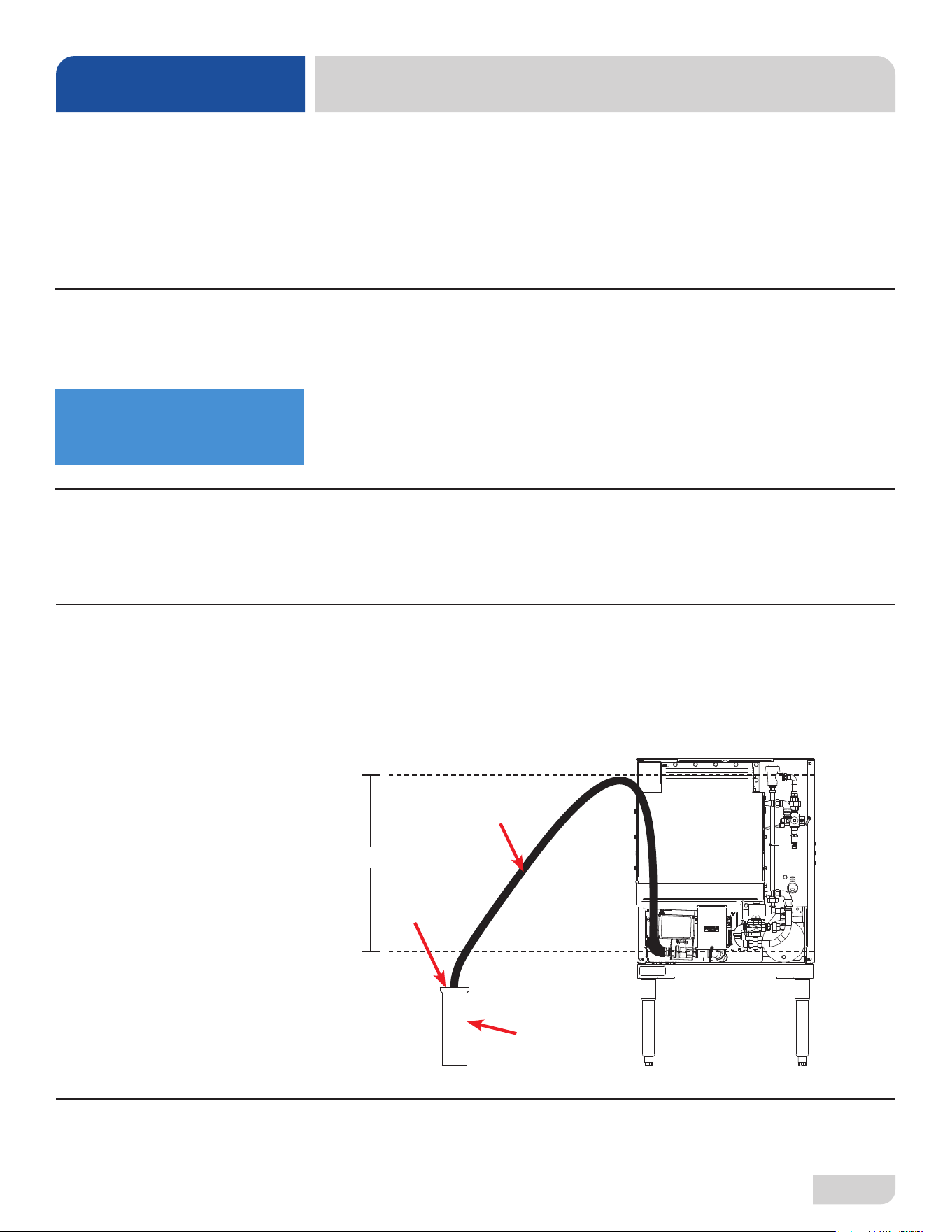
The machine has a pumped (pressure) drain capable of pumping waste water to a
height of 24” above the machine's drain pump and is supplied with a drain hose. There
must be an air-gap between/around the machine drain hose and the oor drain or
sink. The oor drain or sink must be at least 1.5 times larger than the machine drain
hose. If a grease trap is required by code, it should have a ow capacity of 12 GPM.
After installing the incoming ll line and drain hose, turn on the water supply to the
machine. Check for any leaks and repair as required. All leaks must be repaired
before operating the machine.
INSTRUCTIONS
INSTALLATION
WATER SUPPLY
CONNECTIONS:
WATER HARDNESS
LOWER THAN 3 GPG
PRESSURE
REGULATOR
SHOCK ABSORBER
CONNECTING THE
DRAIN LINE
Take care not to confuse
static pressure with
ow pressure!
PLUMBING CHECK
≤24”
Air-gap
Drain Hose
Floor Drain
or Sink
07610-004-54-86-P
8
Electrical and grounding conductors must comply with the applicable portions of the
National Electric Code ANSI/NFPA 70 (latest edition) and/or other electrical codes.
The data plate is located on the left-front of the dishmachine. Refer to the data plate for
machine operating requirements, machine voltage, total amperage, and serial number.
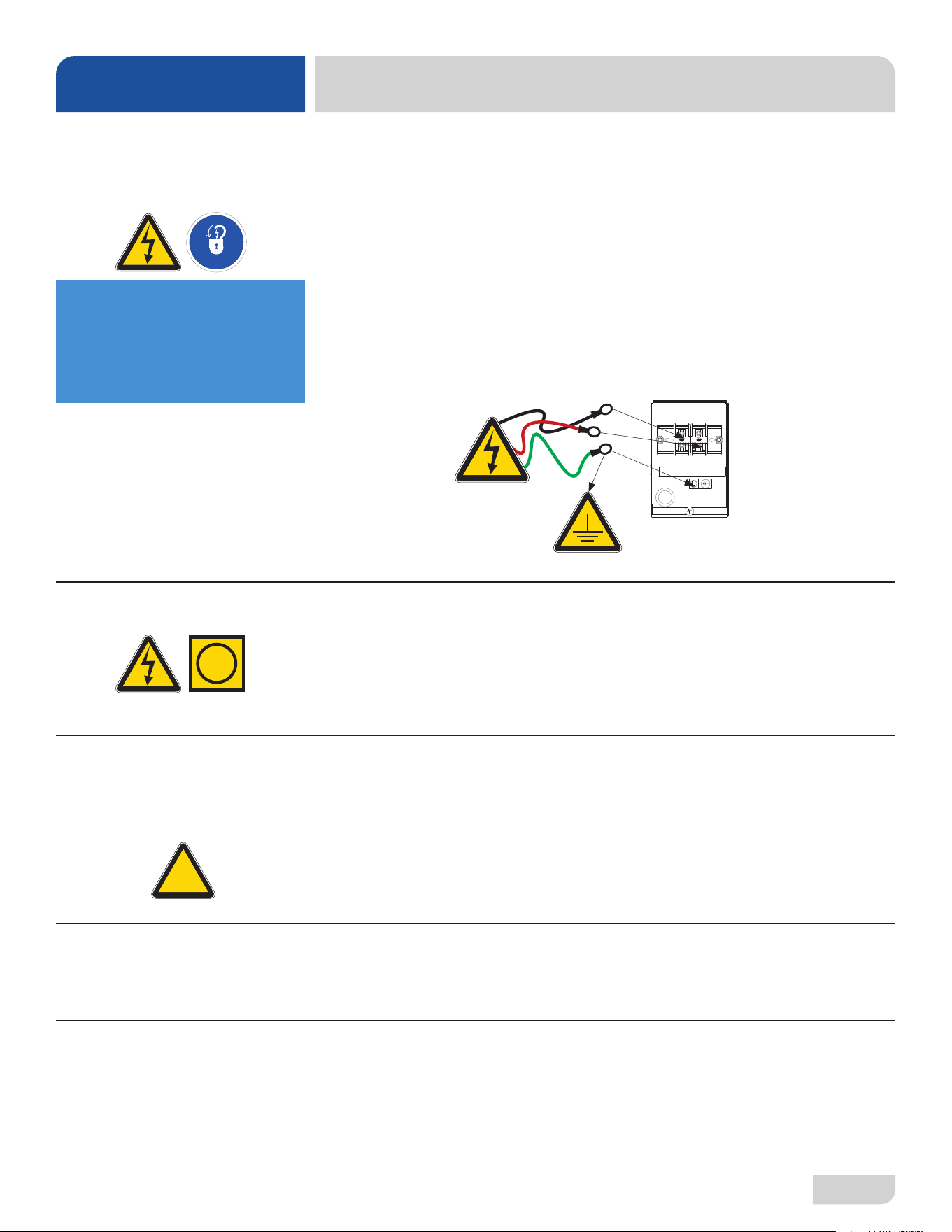
Remove the rear dress panel and set aside. Remove the terminal block box cover. Install
3/4” conduit into the hole in the bottom of the terminal block box. Route power wires and
connect to terminal block. Install the grounding wire onto the lug provided. “DE-OX” or
another similar anti-oxidation agent should be used on all power connections.
Apply power to machine. Check the incoming power at the terminal block and ensure
it corresponds with the voltage listed on the data plate. If not, contact a qualied
service agency to examine the problem. Do not run the machine if voltage is too
high or too low. Advise all proper personnel of the location of the breaker and any
problems. Replace the terminal block box cover and tighten-down the screws.
This is a commercial machine and reaches temperatures that can exceed those
generated by a residential machine. Surrounding countertops, cabinets, ooring
material, and subooring material must be designed and/or selected with these higher
temperatures in mind.
CAUTION! Damage to materials not recommended for higher temperatures will not
be covered under warranty or by the manufacturer.
The temperature setpoints on this unit have been set at the factory. They should only
be adjusted by an authorized service agent.
INSTRUCTIONS
INSTALLATION
ELECTRICAL POWER
CONNECTIONS
Disconnect electrical
power at the breaker or
disconnect switch and
tag-out in accordance with
procedures and codes.
TEMPERATURE
SETPOINTS
SURROUNDING AREA
VOLTAGE CHECK
i
L1 N
Ground
LEVELING
A level machine is important to prevent any damage to the machine during operation
and to ensure the best possible results. The machine comes equipped with adjustable
bullet feet which can be turned using a pair of pliers. Since this machine is a
glasswasher unit, it should be leveled as close as possible to the unit's location before
it is pushed under the counter or into place.
!
CAUTION
9
07610-004-54-86-P
Rinse-aid Detergent
Enjuague Ayuda
Detergente
Détergent
Abrillantador
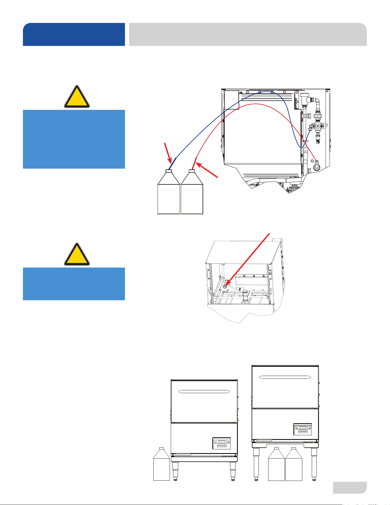
This machine is supplied with detergent and rinse-aid pumps and all necessary
tubing. To connect, simply locate the chemical tubes and place the ends (with tube
stieners) in the appropriate chemical containers (red for detergent and blue for
rinse-aid).
Ensure the detergent tube isn't extending past the port and into the wash chamber.
Chemical containers can be stored under the machine for the Delta HT-E-SEER-T
and nearby for the Delta HT-E-SEER-S. The bottoms of chemical containers cannot
be located any higher than 14” from the oor.
Delta HT-E-SEER-S Delta HT-E-SEER-T
CHEMICAL
CONNECTIONS
INSTRUCTIONS
INSTALLATION
CAUTION! Using deionized
water or other aggressive
uids will result in
corrosion and failure of
components and will void
the warranty.
!
CAUTION
CAUTION! Detergent tube
must not extend past port
into the wash chamber.
!
CAUTION
Rinse-aid
Tube
Stiener
Detergent
Tube
Stiener
07610-004-54-86-P
10
INSTRUCTIONS
INSTALLATION
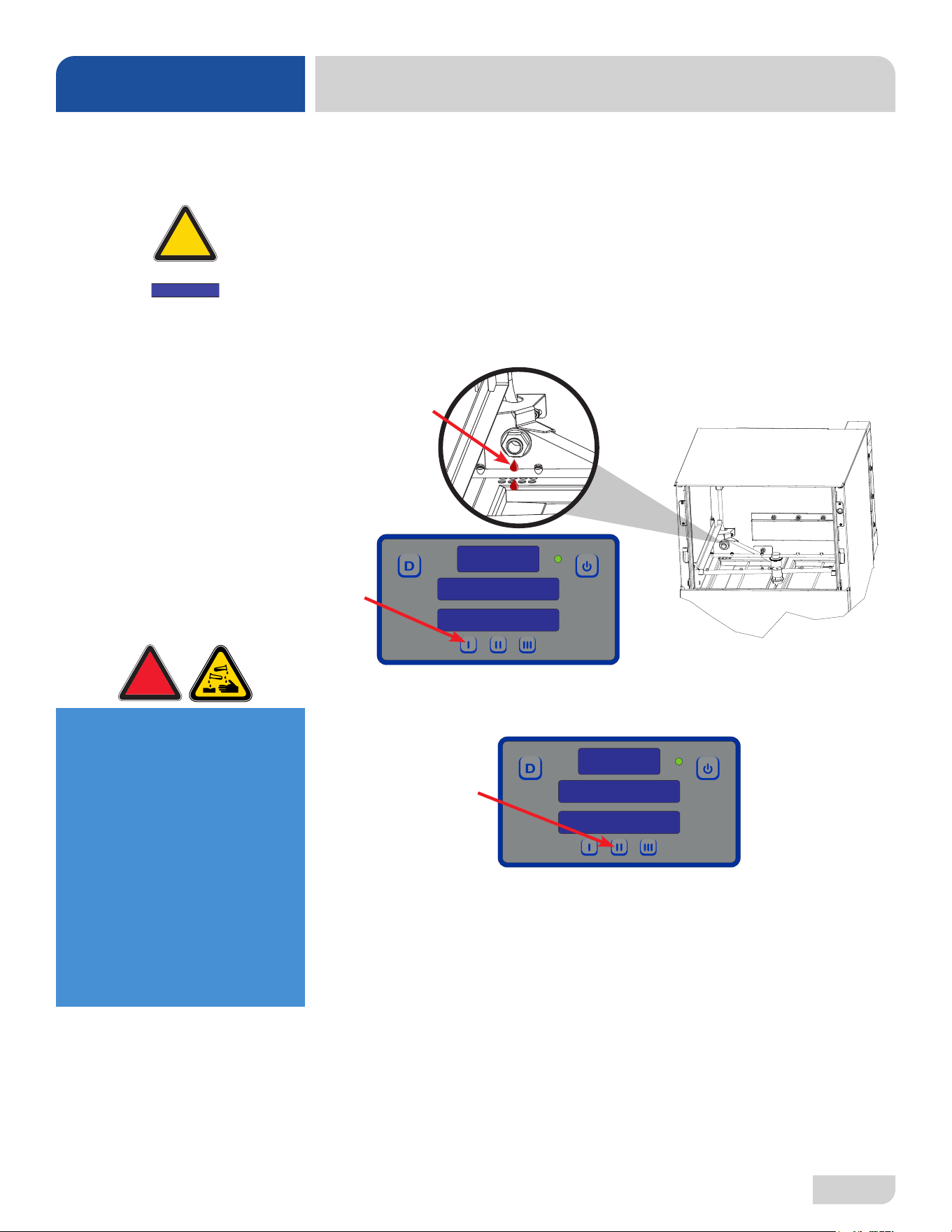
Chemical feeder pumps need priming when the machine is rst installed or if the
chemical lines have been removed and air was allowed to enter.
CAUTION! Water must be in the sump and wash tank before dispensing chemicals.
1. Verify the proper chemical tube stiener inlet is in the proper container.
2. To prime detergent pump, press and hold I button until display shows timer.
Priming cycle defaults to 70 seconds. Observe wash tank during priming cycle.
If too much detergent, press I button to stop priming cycle. If not enough, run
priming cycle again.
3. To prime rinse-aid pump, press and hold II button until display shows timer.
Priming cycle defaults to 180 seconds.
4. The amount of detergent might need adjustment depending on water quality and
type of detergent. The amount of rinse-aid might need adjustment depending on
water hardness and results. Refer to Programming section for instructions on
adjusting amount of chemicals being dispensed.
PRIMING CHEMICAL
FEEDER PUMPS
180
RINSE AID PRIME
70
DETERGENT PRIME
WARNING! Some of the
chemicals used in
dishwashing may cause
chemical burns if they
come in contact with skin.
Wear protective gear when
handling these chemicals.
If any skin comes in
contact with these
chemicals, immediately
follow the instructions
provided with the
chemicals for treatment.
!
WARNING
!
CAUTION
Machines with serial numbers
before 21A390814 prime
dierently. Click here to open
manual with old instructions.
NOTICE
11
07610-004-54-86-P
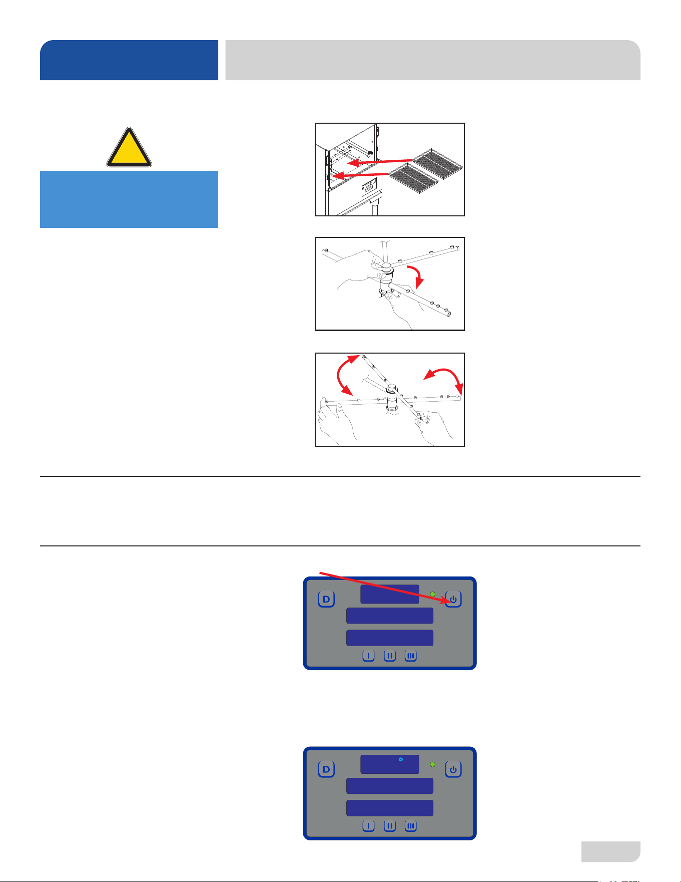
1. Verify strainers are in place and clean.
2. Ensure wash and rinse arms are screwed securely in place and end-caps are tight.
3. Verify wash and rinse arms rotate freely.
4. Conrm chemical levels are correct.
To energize the machine, turn on the power at the service breaker. The voltage should
have been previously veried as correct. If not, the voltage must be veried before
energizing the machine.
1. Press the Power button.
2. The machine will automatically begin the fill cycle.
3. Once the wash tub is filled, the machine displays "HEATING."
4. Wait for wash temperature to display at least 155 °F and for the status to display
"READY" before operating the machine.
OPERATING INSTRUCTIONS
OPERATION
PREPARATION
POWER UP
FILLING THE
WASH TUB
155
F
READY
CYCLE 1
CAUTION! The Preparation
section must be followed
before operating machine!
!
CAUTION
07610-004-54-86-P
12
OPERATING INSTRUCTIONS
OPERATION
Proper ware preparation helps ensure good results and fewer re-washes. If not done
properly, ware might not come out clean and eciency of the dishmachine will be
reduced. Scraps should always be removed from ware before being loaded into
a rack. Pre-rinsing and pre-soaking are good ideas, especially for silverware and
casserole dishes.
Place cups and glasses upside-down in racks so they don't hold water during the
cycle. This machine sanitizes as well as cleans. To do this, ware must be properly
prepared before being placed in machine.
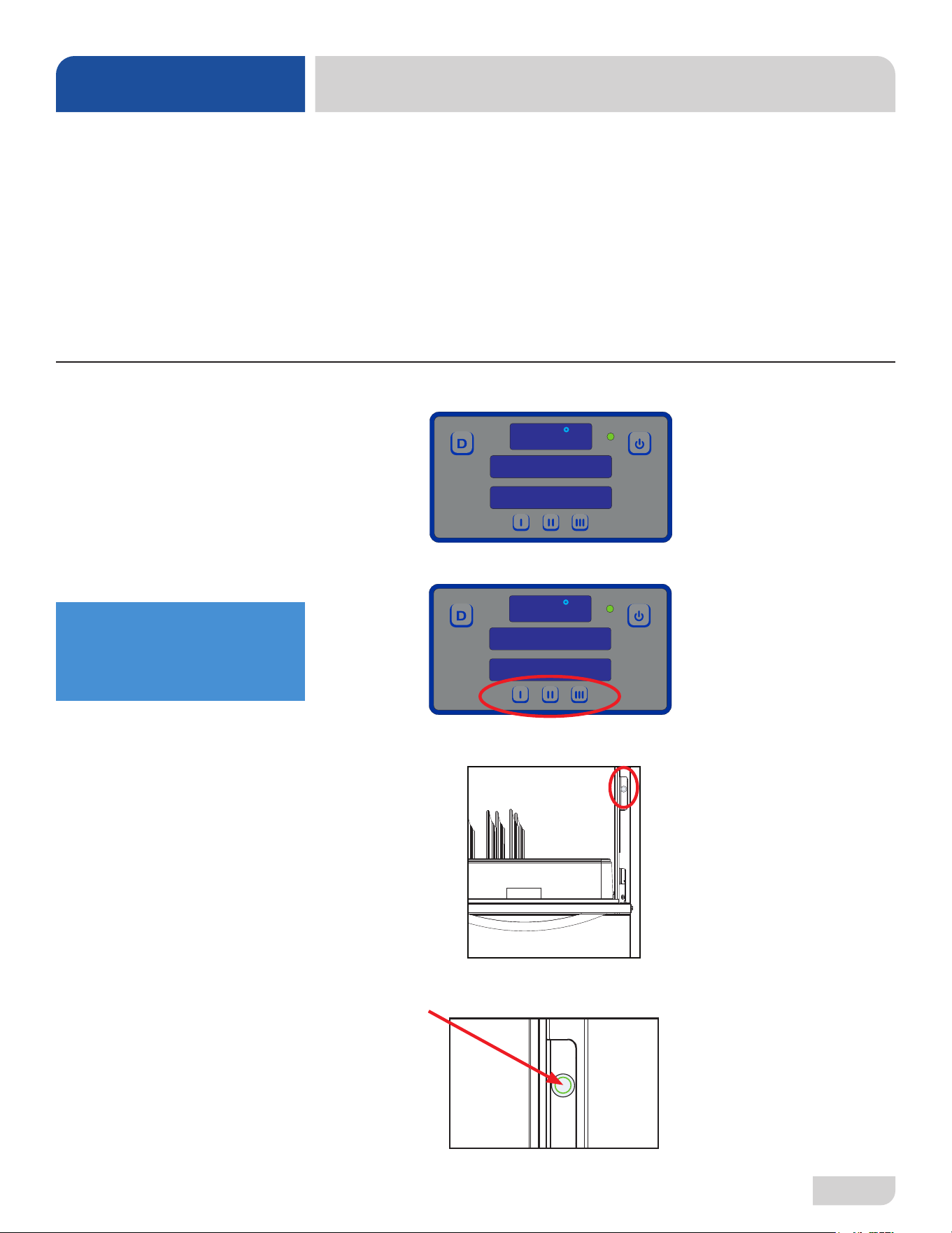
1. Ensure machine is on, at operating temperature, and status displays "READY."
2. Choose cycle.
3. Open door and load rack.
4. Push Start button.
5. LED will turn green. Operator has three seconds to close door before LED goes
out and START button must be pressed again.
WASHING A RACK
OF WARE
WARE
PREPARATION
155
F
READY
CYCLE 1
155
F
READY
CYCLE 1
Cycle I
145 Seconds
Normally-soiled Ware
Cycle II
213 Seconds
Heavily-soiled Ware
Cycle III
313 Seconds
Extremely-soiled Ware
If Cycle II or III is chosen,
machine will stay in
that cycle until
another is chosen.
13
07610-004-54-86-P
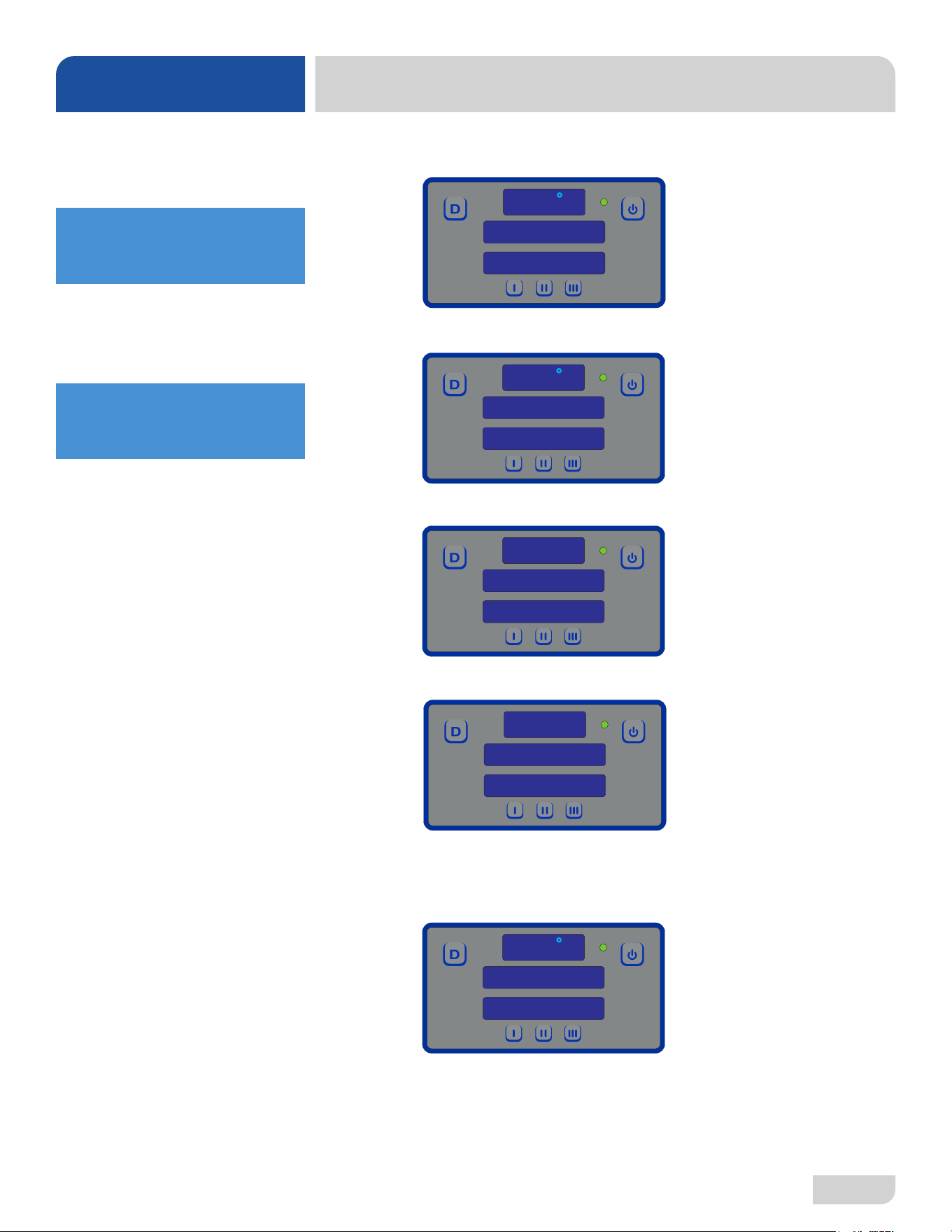
6. Wash cycle automatically starts when door is closed.
7. After the wash cycle is complete, the machine will automatically enter the rinse
cycle.
8. Once the rinse cycle is complete, the machine will automatically enter the sanitize
cycle.
9. After the sanitize cycle is complete, the machine will automatically enter the venting
cycle.
10. After the venting cycle is complete, the machine will automatically go back to
being "READY." Open door and remove rack of ware. To start another cycle, load
another rack of ware, push Start button, and close door.
155
F
WASHING
CYCLE 1
OPERATING INSTRUCTIONS
OPERATION
WASHING A RACK
OF WARE
180
F
RINSING
10 PSI
Temperature shown is
the minimum required
temperature.
Temperature shown is
the minimum required
temperature.
SANITIZE
CYCLE 1
155
F
READY
CYCLE 1
VENTING
CYCLE 1
07610-004-54-86-P
14
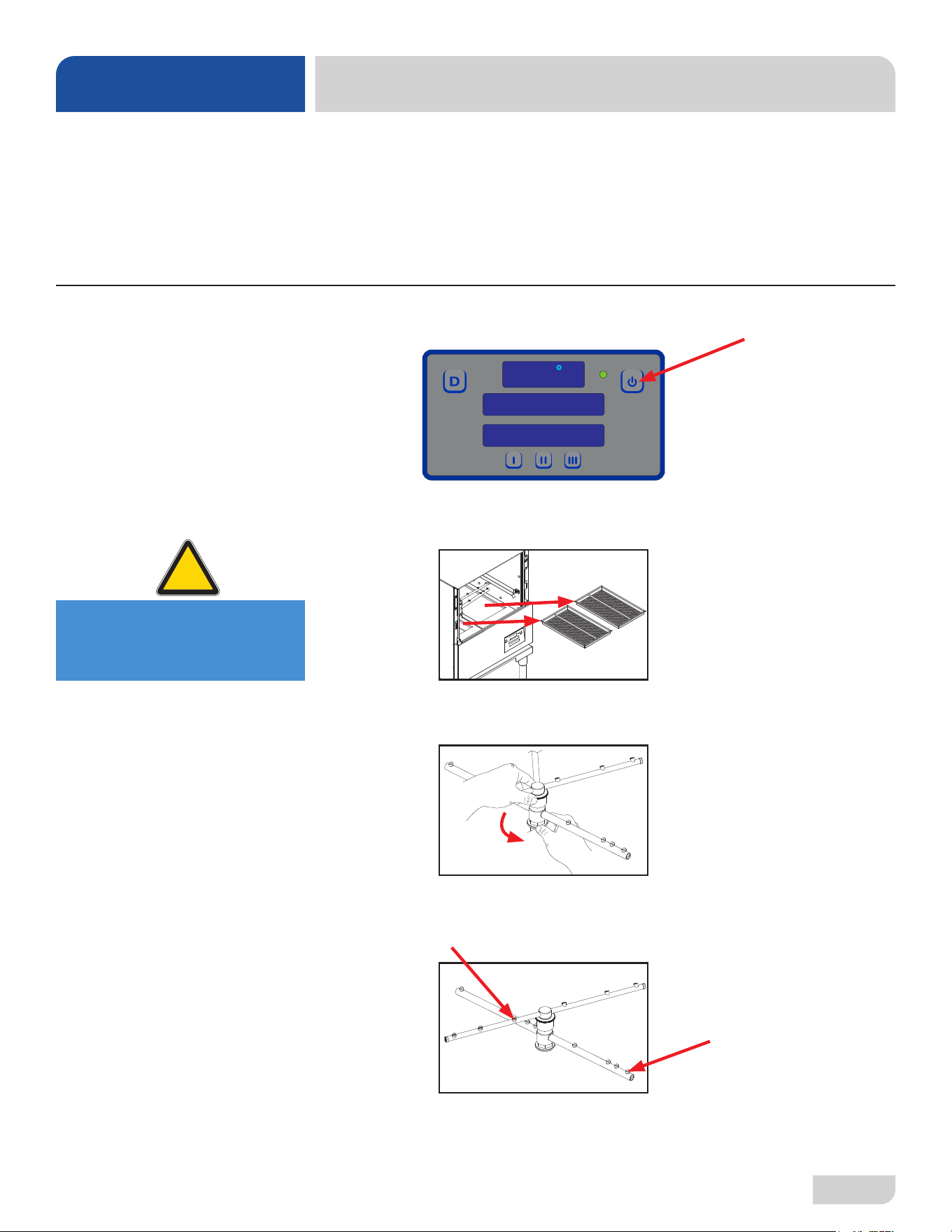
1. Close the door and turn the machine off by pushing the Power button.
2. The drain valve will activate and empty the machine of water.
3. When draining stops, remove and clean the strainers and set aside.
4. Unscrew the wash and rinse arms from their manifolds.
5. Verify the nozzles and arms are free from obstruction. If clogged, remove end-
caps, clean nozzles with a brush, and flush with fresh water.
OPERATIONAL
INSPECTION
SHUTDOWN &
CLEANING
OPERATING INSTRUCTIONS
OPERATION
Based on use, the strainers might become clogged with soil and debris as the
workday progresses. Operators should regularly inspect the strainers to ensure they
have not become clogged. Clogged strainers will reduce the washing capability of
the machine. Instruct operators to clean out the strainers at regular intervals or as
required by workload. Do NOT beat strainers to remove soil and debris!
155
F
READY
CYCLE 1
CAUTION! Do NOT beat
strainers to remove
soil and debris!
!
CAUTION
15
07610-004-54-86-P
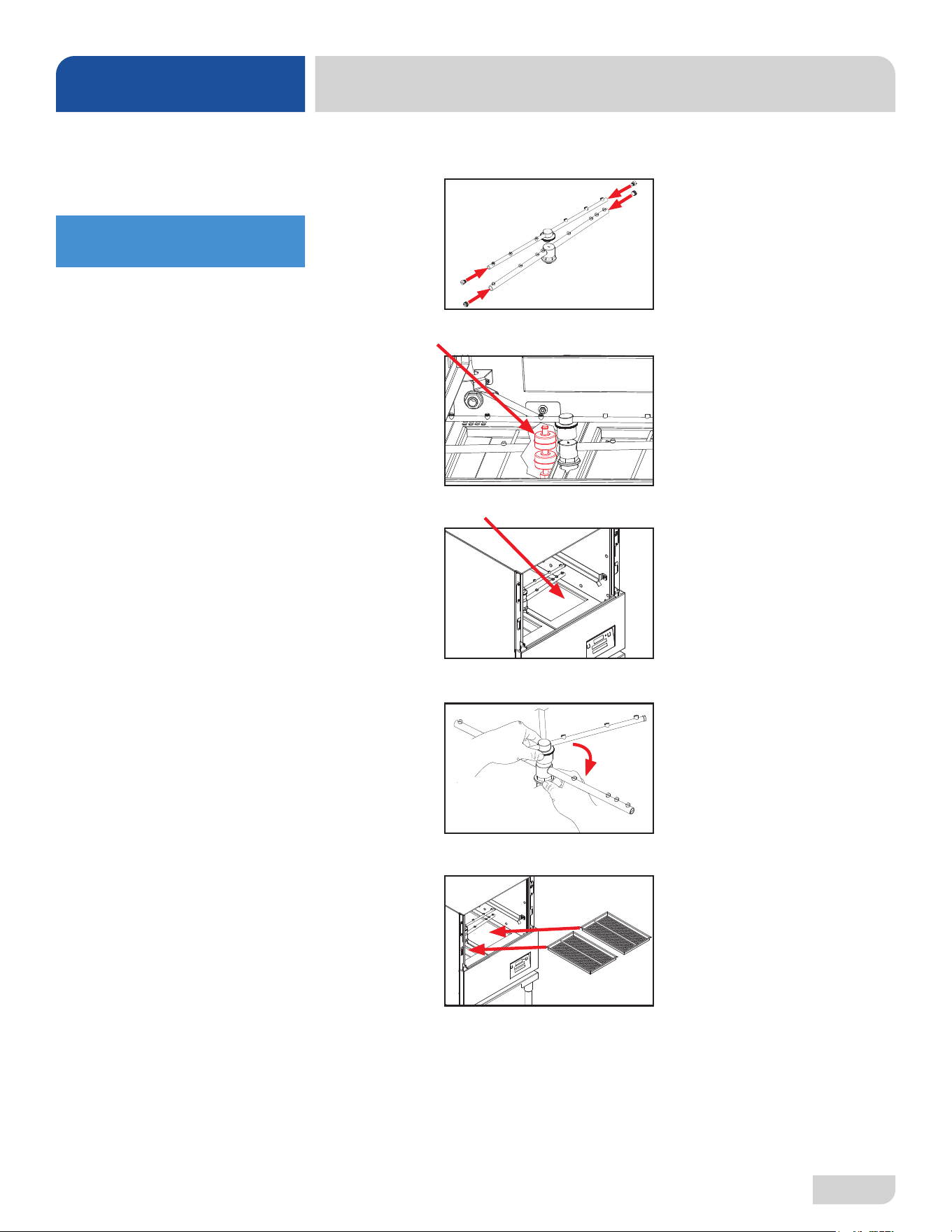
6. Replace end-caps and use a screwdriver to ensure they are tight.
7. Ensure the float (located under left strainer) is free of debris.
8. Spray or wipe out interior of machine.
9. Replace wash and rinse arms.
10. Replace the strainers and ensure they are laying flat.
11. Use stainless steel polish to clean and protect outside of machine.
SHUTDOWN &
CLEANING
OPERATING INSTRUCTIONS
OPERATION
Use a screwdriver to ensure
end-caps are tight.
07610-004-54-86-P
16
OPERATING INSTRUCTIONS
OPERATION
DELIMING
If the machine is equipped
with an SPS and lime is
becoming a frequent
problem, the cartridge
needs to be replaced.
To order a replacement
cartridge, see the Scale
Prevention System page.
In order to maintain machine at its optimum performance level, lime and corrosion
deposits must be removed. The frequency for deliming will be based on water
conditions. A deliming solution is available from your chemical supplier. Read and
follow all instructions on the label.
To delime machine:
1. Remove rinse arms and place in sink with deliming solution (leave for amount of
time recommended by chemical supplier).
2. Replace rinse arms.
3. If machine is full of water, close door, press Power button, and allow machine to
drain and shut-o.
4. Follow Filling the Wash Tub section of this manual.
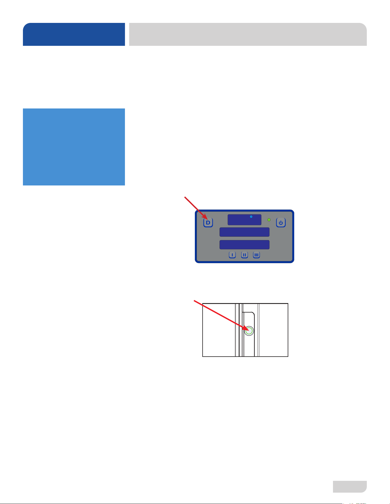
5. Press Delime button on display. Status will display "DELIME."
6. Open door and add amount of deliming solution recommended by chemical
supplier.
7. Press Start button.
8. Close door within three seconds.
9. Machine will delime, drain, and rell.
10. Wait ve minutes, then inspect machine. If machine is not delimed,
run again.
11. When clean, press Delime button. Status will display "READY."
12. Run machine through two regular cycles to remove residual deliming solution.
13. Machine is now ready for normal operation.
155
F
DELIME
ON
17
07610-004-54-86-P
OPERATING INSTRUCTIONS
OPERATION
DETERGENT
CONTROL
i
Detergent usage and water hardness are two factors that greatly contribute to the
machine's operating eciency. Using the proper amount of detergent can become a
source of substantial savings. A qualied water-treatment specialist can determine
what is needed for maximum eciency from the detergent.
• Hard water greatly aects the performance of the machine, causing the amount
of detergent required for washing to increase. If the machine is installed in an
area with hard water, the manufacturer recommends the installation of water
treatment equipment.
• Deposited solids from hard water can cause spotting that will not be removed
with a drying agent. Treated water will reduce this occurence.
• Treated water might not be suitable for use in other areas of operation and it
might be necessary to install a water treatment system for the water going to the
machine only. Discuss this option with a qualied water treatment specialist.
• Properly train operators on how much detergent is to be used per cycle. Meet
with a water treatment specialist and chemical supplier to discuss a complete
training program for operators.
• Water temperature is an important factor in ensuring the machine functions
properly, and the machine's data plate details what the minimum temperatures
must be for the incoming water supply, the wash tank, and the rinse tank. If
minimum requirements are not met, it's possible that dishes will not be clean or
sanitized.
• Instruct operators to observe the required temperatures and to report when they
fall below the minimum allowed. A loss of temperature can indicate a larger
problem.
After no cycle for 30 minutes, Energy Saver Mode initiates and the wash heater
thermostat turns o. This conserves energy while the machine is idle. Pushing the
start button at any time after Energy Saver Mode is activated turns on the wash
heater thermostat, runs a cycle to reheat the wash tank, and resets the timer.
ENERGY SAVER
MODE
07610-004-54-86-P
18
PREVENTATIVE MAINTENANCE
MAINTENANCE
The manufacturer highly recommends that any maintenance and repairs not specically
discussed in this manual only be performed by qualied service personnel.
Performing maintenance on the machine may void a warranty.
By following the operating and cleaning instructions in this manual, users should get
the most ecient results from the machine. As a reminder, here are some steps to
ensure that the machine is used properly:
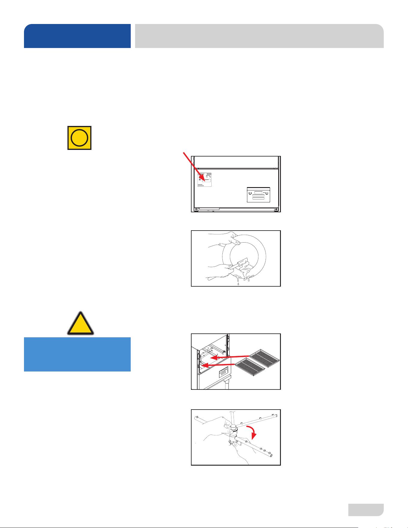
1. Ensure that the water temperatures match those listed on the machine data
plate (on the front-left of machine).
2. Remove as much soil as possible from ware before loading into racks.
3. Ensure that strainers are in place, laying at in the tub, and free of soil and
debris before operating the machine. To clean strainers, wipe them out with a
rag and rinse under a faucet. For stubborn debris, a toothpick can be used. Do
not beat strainers on waste cans; once bent, they will not work properly.
4. Ensure that all wash and rinse arms are secure in the machine before operating.
PREVENTATIVE
MAINTENANCE
i
XXXXXXXXX
ATTENSION:SECONNECTERAUNMINIMUM D’ALIMENTATION 30 AMPERES
DELAI FUSIBLE DE TYPE NON-TEMPS OU LAPROTECTION CONTRE LES SURINTENSITES.
NOTE: WASHAND RINSE HEATER DO NOT OPERATE
AT THE SAME TIME. ELECTRICALLOADS BASED ON WASH
MOTORAND RINSE HEATER (HIGHESTAMP DRAW)
CAUTION: IF THIS MACHINE IS CONNECTED TOACIRCUIT PROTECTED BYFUSES,
USEONLY 30A NON-TIMEDELAY FUSE OR O VERCURRENT
PROTECTION.
SERIALNO.:
60Hz 1 PH 2 WIRE
6.6A
230 VOLT
3/4 HP
MODEL:DELTA HT-E-SEER
Made in the USA
Jackson WWS , Inc
6209 N US HWY25E
Gray, KY40734
(606) 523-9795
09905-004-53-38 B
155°F
180°F
40-90°F
80 SEC
6.6A
17.4A
4 KW
15.9A3.3 KW
28.3A26.3A
WASH MOTOR
RINSE HEATER
TOTALLOAD
OPERATING PARAMETERS
MINIMUM WASH TEMP
MINIMUM RINSE TEMP
MIN/MAX INCOMING WATER TEMP
WASH CYCLE TIME
RINSE CYCLE TIME
WATER FLOW PRESSURE
208 VOLT
9 SEC
3/4 HP
10PSI
WASH HEATER
19.7A
5 KW
21.7A
4.1 KW
MINIMUM CIRCUITAMPACITY
MAXIMUM OVERCURRENT PROTECTION
@208 VOLTS: 28.0AMPS
@230 VOLTS: 30.0AMPS
@208 VOLTS: 30AMPS
@230 VOLTS: 35AMPS
4000897
Conforms to ULStd 921
Conforms to CSA
Std C22.2 No.168
Intertek
4000897
Conforms to NSF Std 3
CAUTION! Do NOT beat
strainers to remove
soil and debris!
!
CAUTION
19
07610-004-54-86-P
PREVENTATIVE MAINTENANCE
MAINTENANCE
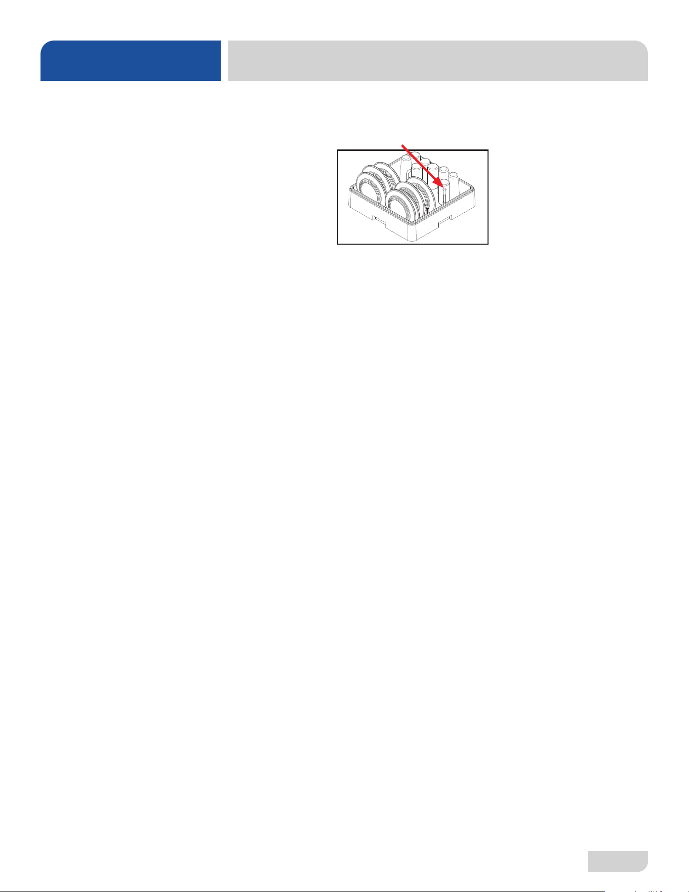
5. Do not overll racks.
6. Ensure that glasses are placed upside-down in the rack.
7. Ensure that all chemicals being injected into the machine have been veried at
the correct concentrations.
8. Clean the machine at the end of every workday (see Shutdown and Cleaning
section).
9. If hard water is present, install an SPS into the water line connecting to the
machine (see the Water Supply Connections section).
10. Always contact a qualied service agency whenever a serious problem arises.
11. Follow all safety procedures, whether listed in this manual or put forth by local,
state, or national codes/regulations.
PREVENTATIVE
MAINTENANCE
07610-004-54-86-P
20
TROUBLESHOOTING
PROGRAMMING
MODEL
CONFIRMATION
A transparent guide to
locating the programming
buttons is included with
machine, behind the kick
panel. Lay the guide over
the display and press
where indicated.
CAUTION! Machine will
not operate properly with
wrong program number!
!
CAUTION
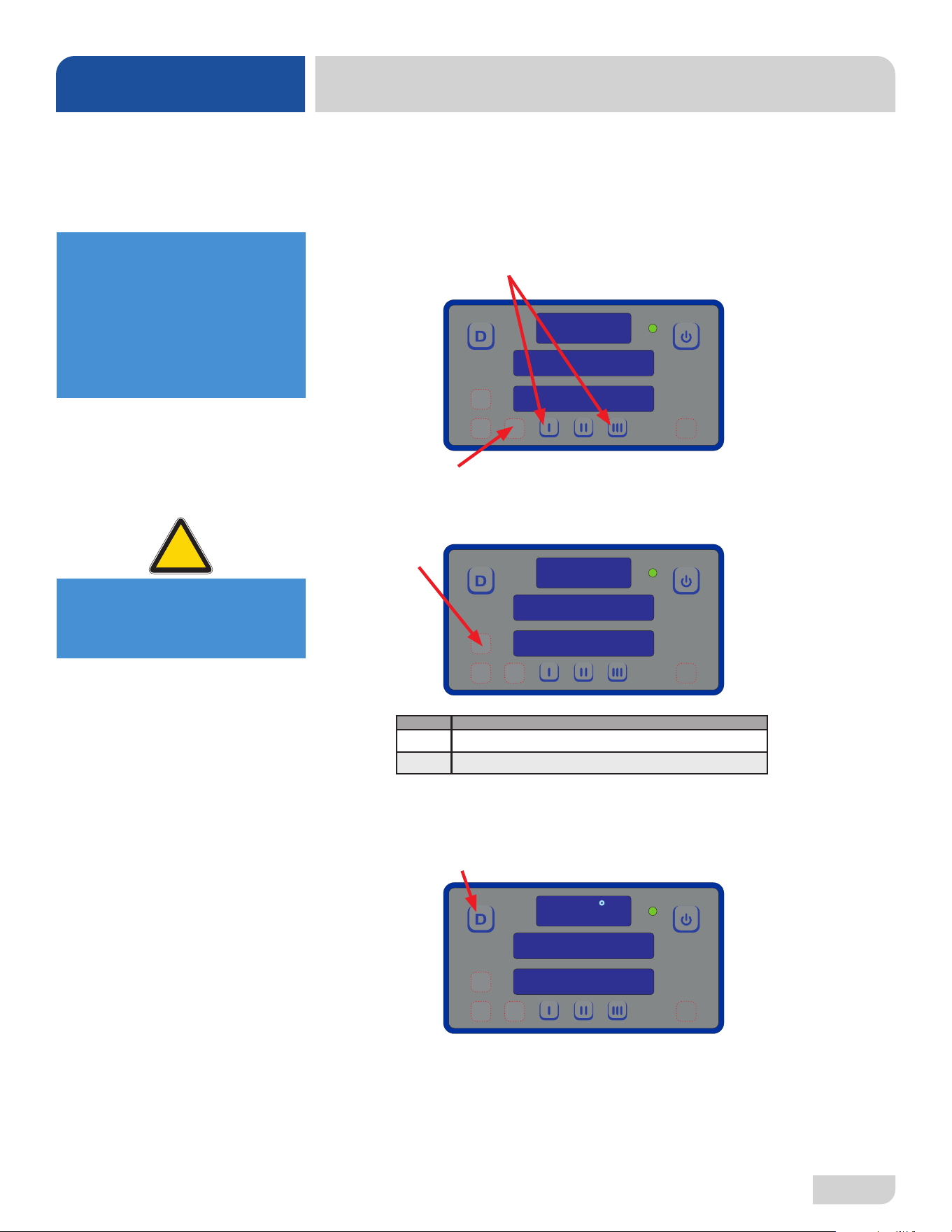
To access programming, machine should be on and not in cycle.
Programming buttons (up-arrow, down-arrow, and select) are hidden
on display and are shown below as red outlines.
Factory Setup (Model Selection)
1. Press and hold I and III buttons until “Program” starts ashing (2–3 seconds).
2. Press select button.
3. Use up-arrow or down-arrow button to change program number to correct
number in table, based on model.
4. Press select button.
5. “Program” will ash.
6. Press delime button to exit.
PROGRAM
PROGRAM
SEE TABLE
READY
CYCLE 1
150
F
Pgrm # Model
7 Delta HT-E-SEER with Serial Number after 23D415452
9 Delta HT-E-SEER with Serial Number before 23D415452
21
07610-004-54-86-P
TROUBLESHOOTING
PROGRAMMING
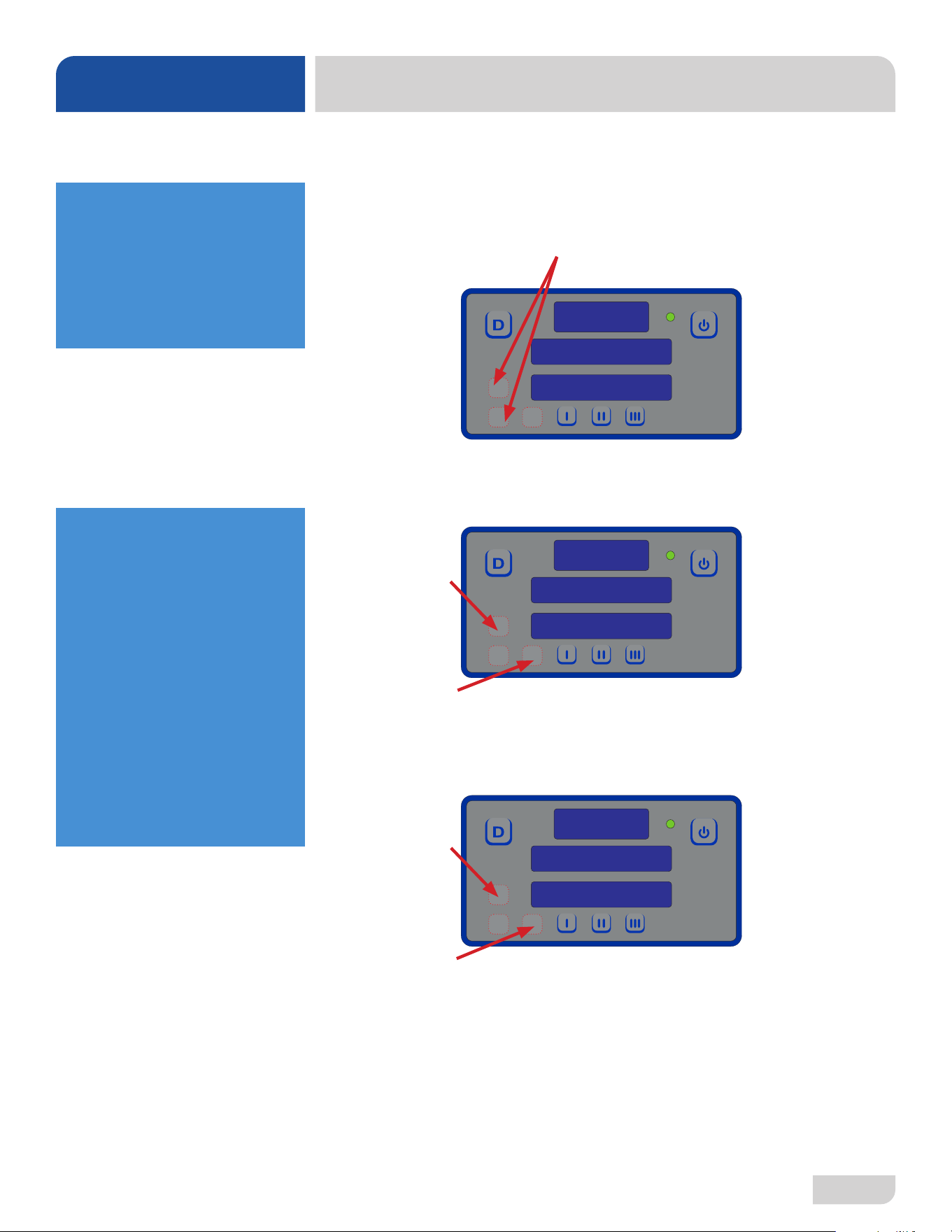
To access programming mode, machine should be on and not in cycle.
Programming buttons (Up-arrow, Down-arrow, and Select) are hidden on display
and are shown below outlined with red dots.
1. Press and hold Up-arrow and Down-arrow buttons until “Setup” ashes (2–3
seconds).
2. Display will then change to “Version” and show rmware versions of the I/O
module and display.
3. Use Up-arrow button to cycle through adjustable settings (will be ashing).
4. Press Select button to choose setting to change.
• Regardless of category, Steps 5–7 remain the same.
5. Use Up-arrow button to change options (will be ashing). Numerical options are
shown in top window.
6. Press Select button to accept changes.
7. Press Delime button to exit.
USER SETUP
SETUP
LANGUAGE
LANGUAGE
ENGLISH
A transparent guide to
locating the programming
buttons is included with
machine, behind the kick
panel. Lay the guide over
the display and press
where indicated.
ADJUSTABLE SETTINGS
Language
Temperature Scale
Wash Temperature
Boost Temperature
Wash Oset
Rinse Oset
Boost Oset
Spare Oset
Detergent Dispense Time
Rinse-aid Dispense Time
Detergent Priming Time
Rinse-aid Priming Time
Saver Wash Temp
Saver Activation Delay
07610-004-54-86-P
22
FAULT CODES
TROUBLESHOOTING
DISPLAY SHOWS POSSIBLE CAUSES REMEDY
“F1 Service needed,”
“No water in Booster”
1. Low or no water pressure.
2. Faulty inlet valve or ll relay.
3. Contactor to booster heater not turning o.
4. Faulty temperature input (P12) on IO
module.
5. Faulty temperature probe (T3).
6. Faulty oat switch allows heaters to
operate with no water in tub.
1. Verify incoming water pressure is 10 ± 2 PSI.
2. Verify that ll relay is supplying voltage to ll solenoid.
Replace faulty component.
3. Check for welded contacts. Verify that output from IO
module turns o when above the set temperature.
4. Substitute a 1.2 kΩ resistor for T3, and verify that booster
heater turns o. If not, replace IO module.
5. Verify that the booster-probe resistance is correct with
respect to temperature (see table on pg. 24). If not, replace
T3.
6. Replace oat switch.
“F2 Service needed,”
“Check booster
thermostat”
1. Contactor to booster heater not turning o.
2. Faulty temperature input (P12) on IO module.
3. Faulty temperature probe (T3).
1. Check for welded contacts. Verify that output from IO
module turns o when above the set temperature.
2. Substitute a 1.2 kΩ resistor for T3, and verify that booster
heater turns o. If not, replace IO module.
3. Verify that the booster probe resistance is correct with
respect to temperature (see table on pg. 24). If not, replace
T3.
“F3 No water in wash
tank,” “Check inlet
water and door”
1. Malfunction of ll solenoid or ll relay.
2. Door is open, which inhibits ll mode.
3. Faulty door switch.
1. Replace faulty component.
2. Close door to activate door switch.
3. Replace or adjust door switch.
"F4 Service needed,"
"Check incoming
power"
1. Incoming power not properly connected.
2. L3 is missing (3-phase machines only).
1. Check connections to heater.
2. Verify that L3 is present and connected properly.
“F5 Service needed,”
“Check booster
thermostat and high
limit”
1. Faulty temperature input (P12) on IO
module.
2. Faulty temperature probe (T3).
3. Faulty high-limit switch.
4. Faulty booster heater.
5. Booster-heater contactor not energizing.
1. Substitute a 1.8 kΩ resistor for T3, and verify that booster
heater turns on. If not, replace IO module.
2. Verify that T3 resistance is consistent with the table on
pg. 24. If not, replace T3.
3. Replace high-limit switch.
4. Check booster heater for proper resistance. Replace if
incorrect.
5. Verify that drive voltage to contactor coil is present
during a call for heat and that contactor closes. If voltage is
present, replace contactor. If voltage is not present, check
wiring.
23
07610-004-54-86-P
“F6 Service needed,”
“No water in wash tank”
1. Low or no water pressure.
2. Faulty inlet valve or ll relay.
3. Contactor to wash heater not turning o.
4. Faulty temperature input (T1) on IO
module.
5. Faulty temperature probe (T1).
6. Faulty oat switch allows heaters to
operate with no water in tub.
1. Verify incoming water pressure is 10 ± 2 PSI.
2. Verify that ll relay is supplying voltage to ll solenoid.
Replace faulty component.
3. Check for welded contacts. Verify that output from IO
module turns o when above the set temperature.
4. Substitute a 1.2 kΩ resistor for T1, and verify that wash
heater turns o. If not, replace IO module.
5. Verify that T1 resistance is correct with respect to
temperature (see table on pg. 24). If not, replace T1.
6. Replace oat switch.
“F7 Service needed,”
“Check wash tank
thermostat”
1. Contactor to wash heater not turning o.
2. Faulty temperature input (P10) on IO
module.
3. Faulty temperature probe (T1).
1. Check for welded contacts. Verify that output from IO
module turns o when above the set temperature.
2. Substitute a 1.2 kΩ resistor for T1, and verify that wash
heater turns o. If not, replace IO module.
3. Verify that T1 resistance is correct with respect to
temperature (see table on pg. 24). If not, replace T1.
“F8 No water in wash
tank,” “Check inlet
water and door”
1. Malfunction of ll solenoid or ll relay.
2. Door is open, which inhibits ll mode.
3. Faulty door switch.
1. Replace faulty solenoid or ll relay.
2. Close door to activate door switch.
3. Replace or adjust door switch.
DISPLAY SHOWS POSSIBLE CAUSES REMEDY
“F9 Service needed,”
“Check incoming
power”
1. Incoming power not properly connected.
2. L3 is missing (3-phase machines only).
1. Check connections to heater.
2. Verify that L3 is present and connected properly.
“F10 Service needed,”
“Check wash tank
thermostat and high
limit”
1. Faulty temperature input (T1) on I/O
module.
2. Faulty temperature probe (T1).
3. Faulty high-limit switch.
4. Faulty wash heater.
5. Wash-heater contactor not energizing.
1. Substitute a 1.8 kΩ resistor for T1, and verify that wash
heater turns on. If not, replace I/O module.
2. Verify that T1 resistance is correct with respect to
temperature (see table on pg. 24). If not, replace T1.
3. Replace high-limit switch.
4. Check wash heater for proper resistance. Replace if
incorrect.
5. Verify that drive voltage to contactor coil is present during
a call for heat and that contactor closes. If voltage present,
replace contactor. If voltage not present, check wiring.
F11 Service needed
–check wash tank
thermostat
Faulty temperature probe (T1). Replace probe that connects to P10.
FAULT CODES
TROUBLESHOOTING
07610-004-54-86-P
24
FAULT CODES
TROUBLESHOOTING
"F12 Service needed,"
"Check booster
thermostat"
Faulty temperature probe (T3). Replace probe that connects to P13.
"F13 Communication
error,"
"Check 6-pin cable"
1. Loose connection in 6-pin cable between
display board and I/O module.
2. Faulty 6-pin cable between display board
and I/O module.
3. Faulty communication port on I/O module
or display board.
1. Fully disconnect 6-pin cable at each end, and reconnect
each end until a click is heard.
2. Inspect for broken wire or unseated terminal by gently
pulling on each wire at each end of the cable. Reseat any
loose terminals by inserting it fully into the housing using
long-nosed pliers. Replace cable if broken wire is found.
3. Temporarily substitute a veried good display board, and
check if F13 message recurs. If so, repeat substitution with
a good I/O module.
"F14 Service needed,"
"Check incoming
water pressure or
pressure switch"
1. Low or no water pressure.
2. Faulty pressure switch.
3. Faulty ll valve or ll valve not receiving
power.
1. Verify correct PSI.
2. Replace pressure switch.
3. Check continuity and replace if faulty.
"F16 LLC violation" Faulty or corroded probe. Clean or replace probe.
"F17 Excessive inlet
temp"
Inlet water supply too hot. Ensure inlet water supply is at required temperature.
DISPLAY SHOWS POSSIBLE CAUSES REMEDY
RESISTANCE-TO-TEMPERATURE VALUES
R (kΩ) °F
11.58 69.8
10.37 75.2
9.30 80.6
7.78 89.6
3.05 140.0
2.54 150.8
2.18 159.8
1.58 179.6
1.45 185.0
1.33 190.4
1.16 199.4
0.96 212.0
25
07610-004-54-86-P
OBSERVATION POSSIBLE CAUSE REMEDY
Water overow
from bottom of
door.
1. Clogged drain.
2. Machine not level.
3. Excessive inlet pressure.
4. Detergent foaming.
5. Wash or rinse arm end-cap missing.
1. Remove obstruction.
2. Level machine or increase height to the front.
3. Install pressure regulating valve or adjust if one is present.
Ensure ow meets data plate specication.
4. Reduce detergent quantity.
5. Replace end-cap.
Wash motor
doesn’t
operate on
wash.
1. Loose or broken wires.
2. Defective Start button.
3. Defective motor contactor.
1. Reconnect or replace wires in motor.
2. Adjust button or replace.
3. Replace.
Little or no water
coming through
the rinse
assemblies.
1. Limed-up rinse heads or piping.
2. Low water pressure.
1. Delime rinse heads.
2. Increase pipe size to machine.
Adjust pressure regulating valve.
Rinse water runs
continuously
with breaker
turned o.
1. Defective plunger in solenoid valve.
2. Defective diaphragm in solenoid valve.
1. Replace plunger.
2. Replace diaphragm.
WARNING! Inspection, testing, and repair of electrical equipment should only be performed by qualied service
personnel. Certain procedures in this section require electrical tests or measurements while power is applied
to the machine. Exercise extreme caution at all times. If test points are not easily accessible, disconnect
power, attach test equipment, and reapply power to test. When replacing electrical parts, disconnect power at
circuit breaker.
!
WARNING
i
TROUBLESHOOTING
TROUBLESHOOTING
07610-004-54-86-P
26
Wash
temperature not
within range.
1. Water level low.
2. RTD setpoint too low.
3. Defective RTD.
4. Wash heater defective.
5. Defective heater contactor.
1. Check water level. If low, run new ll cycle.
2. Adjust setpoint.
3. Replace RTD.
4. Replace heater element.
5. Replace contactor.
Rinse
temperature not
within range.
1. RTD is defective.
2. Incoming rinse water does not
meet minimum temperature on
machine data plate.
3. Rinse heater damaged.
4. Setpoint screens set low.
5. Defective heater contactor.
1. Replace if necessary.
2. Adjust as required.
3. Check amperage. Replace if necessary.
4. Adjust rinse tank setpoint.
5. Replace contactor.
Machine
doesn’t drain
when power
button is
pressed.
1. Drain clogged.
2. Defective drain valve.
3. Defective wash pump.
4. Defective motor contactor.
5. Defective timer.
1. Remove obstruction.
2. Replace drain valve.
3. Replace wash pump.
4. Replace contactor.
5. Replace timer.
Incorrect water
pressure
displayed
during Fill or
Rinse.
1. Water turned o.
2. Transducer disconnected.
3. Pressure transducer defective.
1. Turn water on.
2. Verify wiring.
3. Replace pressure transducer.
TROUBLESHOOTING
TROUBLESHOOTING
OBSERVATION POSSIBLE CAUSE REMEDY
WARNING! Inspection, testing, and repair of electrical equipment should only be performed by qualied service
personnel. Certain procedures in this section require electrical tests or measurements while power is applied
to the machine. Exercise extreme caution at all times. If test points are not easily accessible, disconnect
power, attach test equipment, and reapply power to test. When replacing electrical parts, disconnect power at
circuit breaker.
!
WARNING
i
27
07610-004-54-86-P
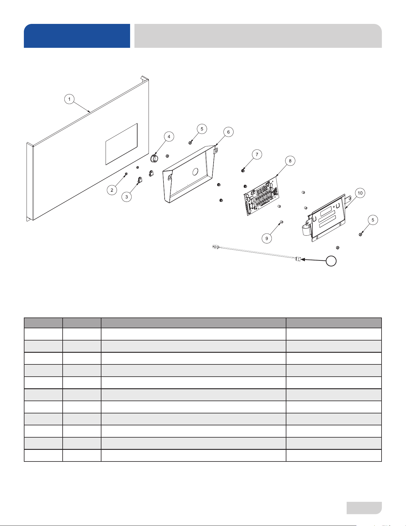
ITEM QTY DESCRIPTION PART NUMBER
1 1 Power Connection Decal 09905-011-47-35
2 1 Terminal Block Box 05700-004-36-47
1 Terminal Box Cover (not shown) 05700-003-27-70
3 1 Strain Relief 05975-003-37-56
4 1 Terminal Block Track 05700-000-43-60
5 2 Terminal Block 05940-500-02-19
6 2 Locknut, 10-24 Hex with Nylon Insert 05310-373-01-00
7 1 Decal, L1, N 09905-011-62-72
8 1 Ground Lug 05940-200-76-00
6
7
5
4
8
1
3
2
TERMINAL BLOCK BOX
PARTS
07610-004-54-86-P
28
CONTROL KICK PANEL
PARTS
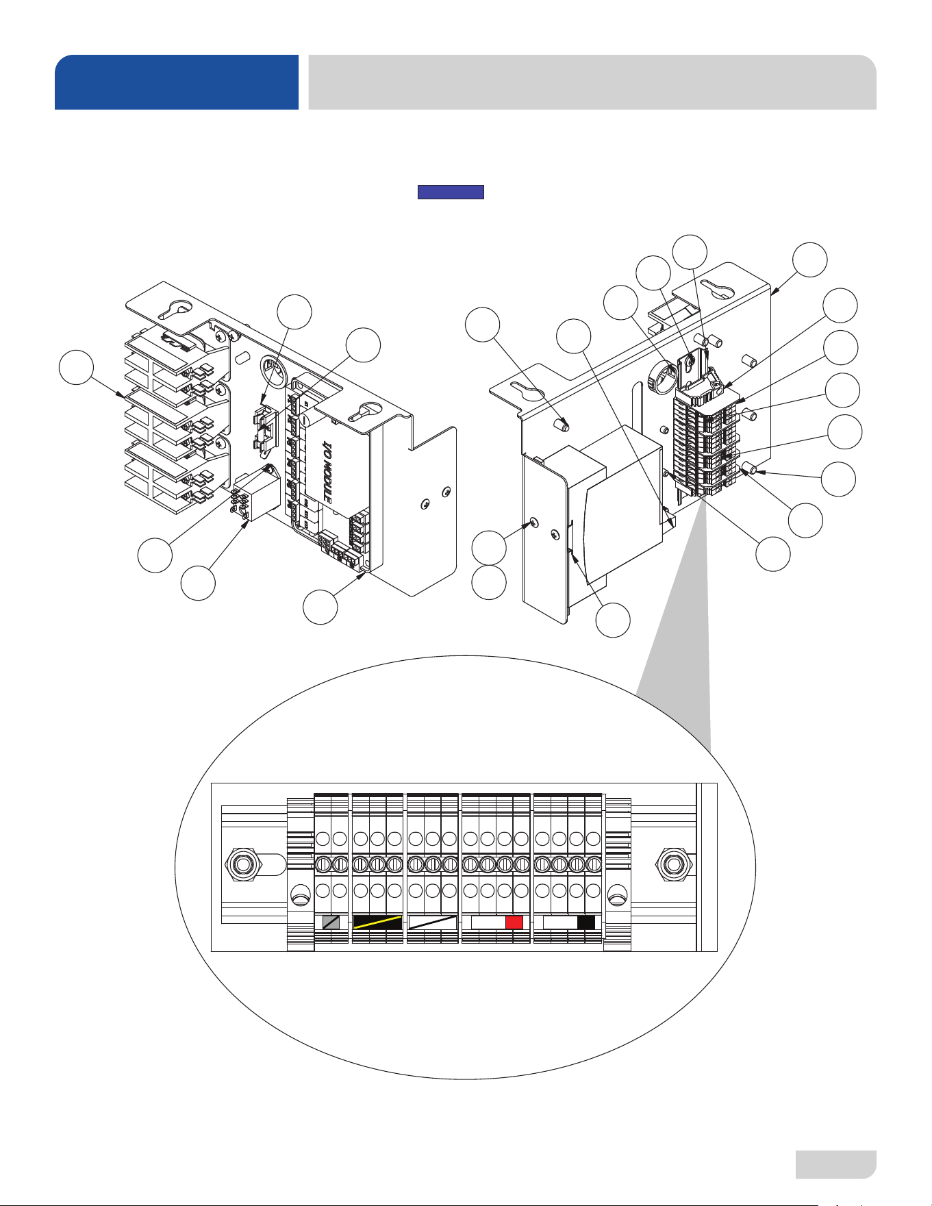
ITEM QTY DESCRIPTION PART NUMBER
1 1 Control Kick Panel 05700-004-52-40
2 2 Locknut, 6-32 Hex with Nylon Insert 05310-373-03-00
3 2 P-clamp, 1/4" ID 05975-002-61-42
4 1 Bushing, Snap 05975-210-09-00
5 4 Locknut, 10-24 Hex with Nylon Insert 05310-373-01-00
6 1 Cover, Display 05700-004-52-43
7 4 Nut, Thumb 6-32 Nylon 05310-002-83-12
8 1 PCB, Digital Display 05700-004-52-37
9 4 Spacer, Unthreaded, 9/32" Nylon 05975-004-47-89
10 1 Panel & Membrane Switch Assembly 05700-004-68-71
11 1 Communication Cable 05700-004-33-64
11
Complete Control Kick Panel Assembly
05700-004-52-41
07610-004-54-86-P
30
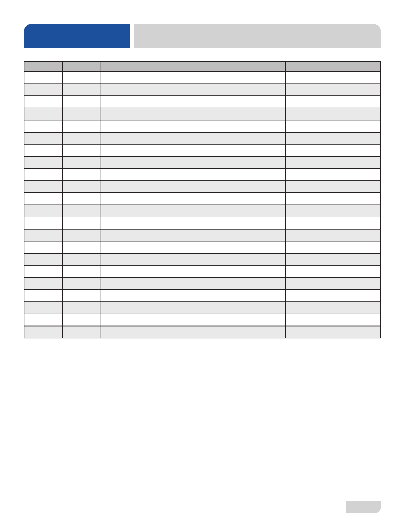
ITEM QTY DESCRIPTION PART NUMBER
1 3 Contactor, 30 A 240 V 05945-002-74-20
2 1 Relay 05945-111-89-75
3 1 Soft Start 05945-004-55-75
4 1 I/O Module 06401-005-05-85
5 1 Dinrail, 5 3/4” 05700-021-72-75
6 16 Terminal Block 05999-004-90-68
7 5 Separator, Terminal Block 05999-004-90-67
8 2 End Bracket, Terminal 05999-004-90-66
9 2 Jumper Bars, 3-pole 05999-004-90-71
10 15 Tag, Marking 05999-004-90-72
11 1 Holder, 6-pole Fuse 05920-002-42-13
12 1 Bushing, Snap, 1 1/8" 05975-210-08-00
13 1 Dinrail, 2” 05700-002-36-09
14 1 Panel, Electrical 05700-004-97-31
15 2 Screw, 10-32 x 1” 05305-002-19-42
16 3 Screw, 6-32 x 3/8” 05305-002-25-91
17 3 Nut, Plated 05340-118-04-00
18 9 Screw, 10-32 x 1/2” 05305-002-80-88
19 11 Fastener 05340-111-58-10
20 2 Screw, 10-32 x 1/4” 05305-173-01-00
21 2 Locknut, 10-32 with Nylon Insert 05310-004-28-70
22 1 Fuse, Time-delay, 8 A, 250 V 05920-004-85-54
ELECTRICAL PANEL
PARTS
07610-004-54-86-P
32
PARTS
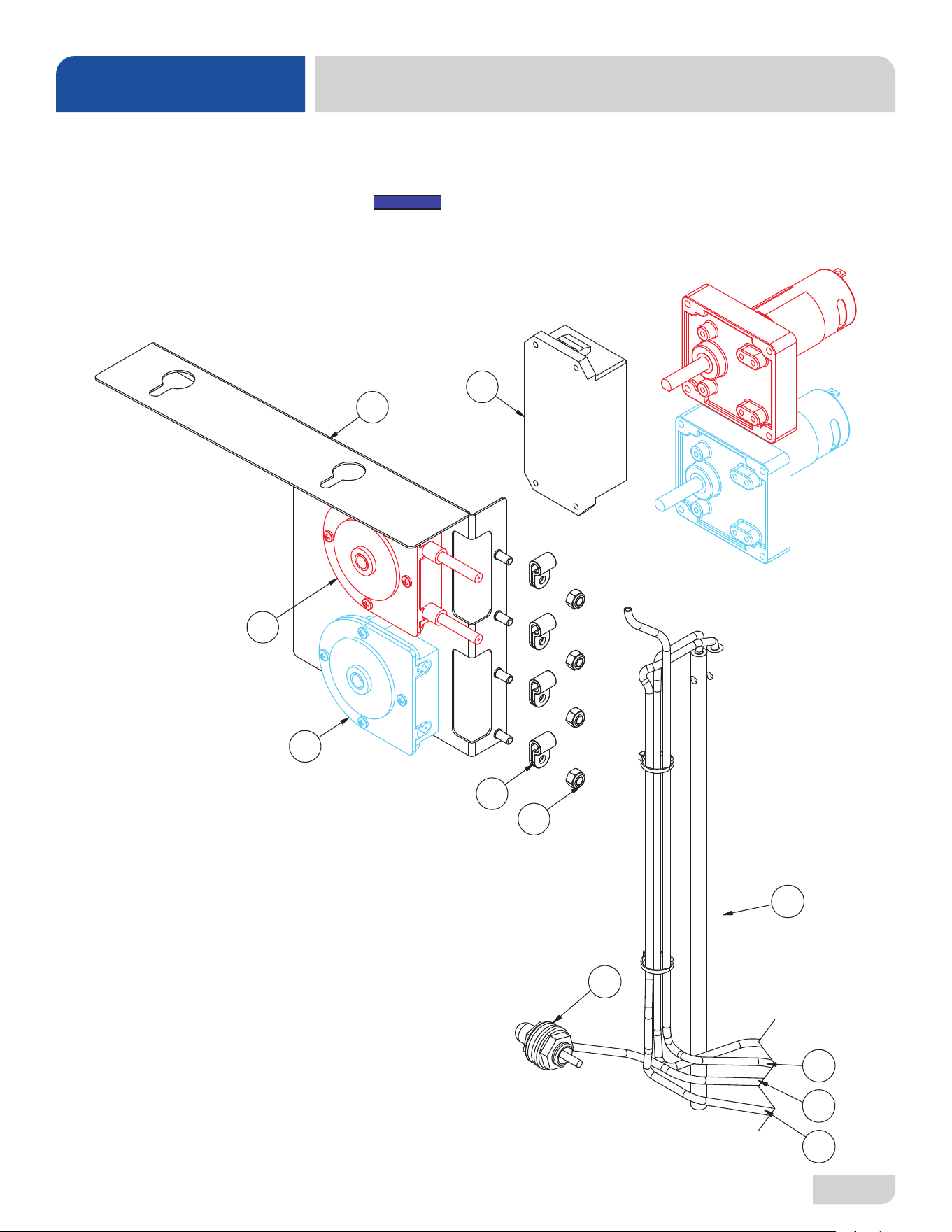
CHEMICAL FEEDER PUMP ASSEMBLY
ITEM QTY DESCRIPTION PART NUMBER
1 1 Power Supply 05950-004-81-79
2 1 Panel, Peri-pump 05700-004-99-72
3 1 Peri-pump Assembly, 14 RPM 05700-004-71-63
4 1 Peri-pump Assembly, 38 RPM 05700-005-00-29
5 4 P-clamp, 1/4" ID 05975-002-61-42
6 4 Locknut, 10-24 Hex with Nylon Insert 05310-373-01-00
7 2 Stiener, Chemical Tube 05700-002-66-49
8 1 Chemical Port Assembly 05700-004-30-86
9 1 Tubing, Blue, 1/4" 04720-604-11-00
10 1 Tubing, Red, 1/4" 04720-601-12-00
11 1 Tubing, Clear, 1/8" 04720-111-58-09
33
07610-004-54-86-P
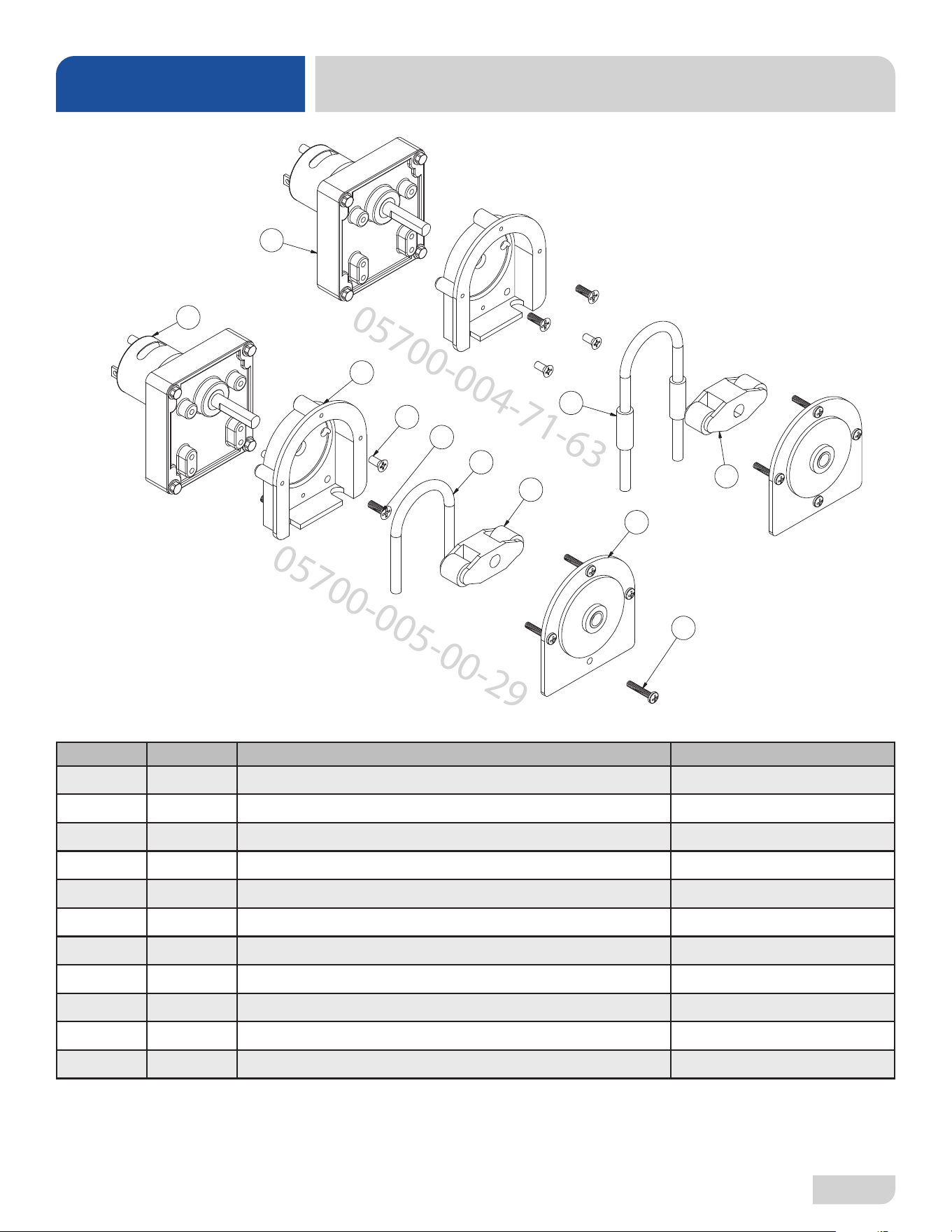
CHEMICAL FEEDER PUMPS
PARTS
0
57
0
0-
005-00-2
9
10
9
8
1
2
6
7
3
4
5
0
5
7
0
0-
004-71-6
3
11
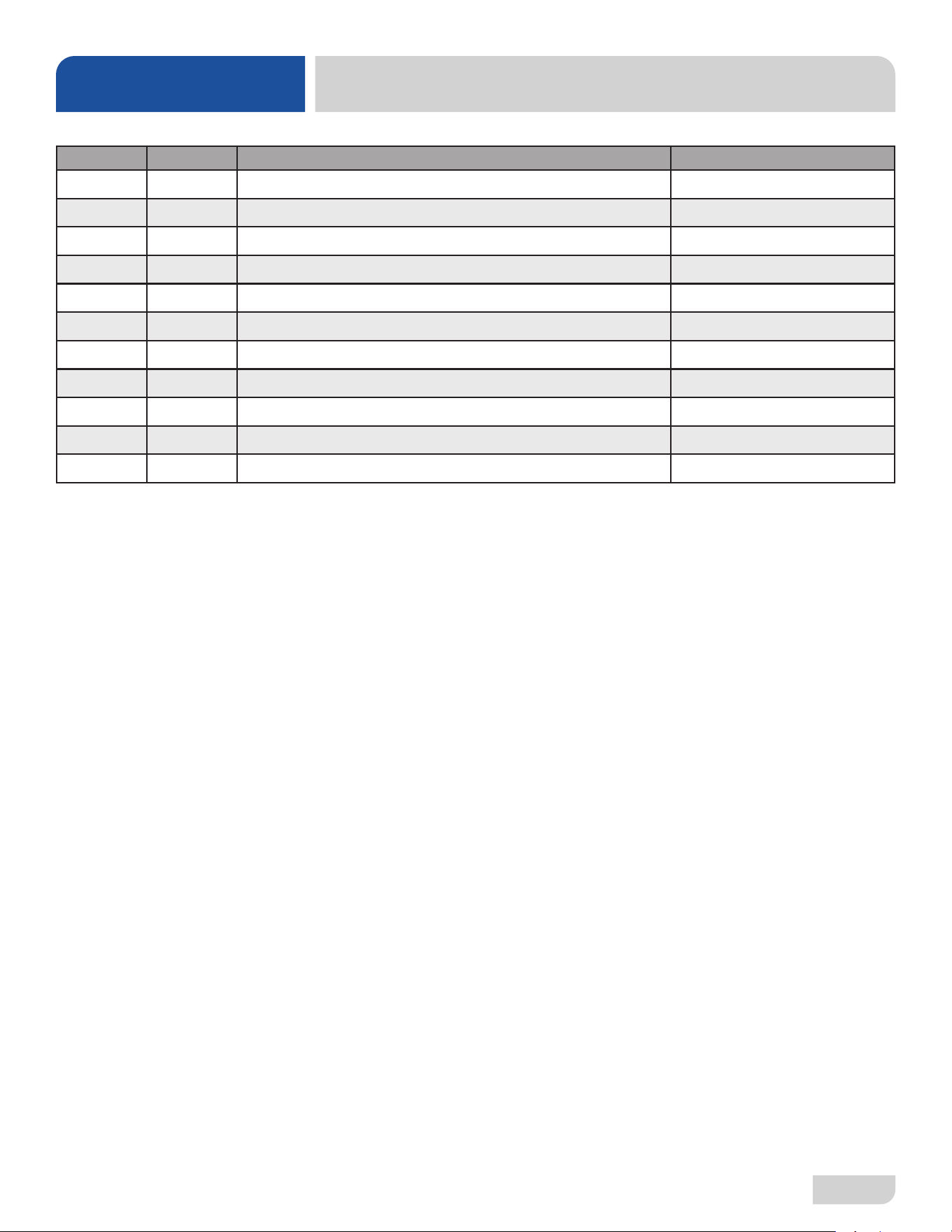
ITEM QTY DESCRIPTION PART NUMBER
1 2 Pump Housing 04320-111-37-09
2 4 Screw, 8-32 x 3/8" Phillips 05305-011-37-07
3 1 Roller, Plastic 04320-002-82-28
4 2 Pump Cover 04320-111-37-08
5 8 Screw, 6-32 x 3/4" Phillips 05305-011-37-05
6 4 Screw, 8-32 x 1/2" Phillips 05305-011-37-06
7 1 Tube, Squeeze, 8" 05700-003-22-89
8 1 Motor, 38 RPM 04320-004-99-36
9 1 Roller, Plastic 04320-111-65-27
10 1 Tube, Squeeze, 9" 05700-011-65-21
11 1 Motor, 14 RPM 04320-011-63-33
35
07610-004-54-86-P
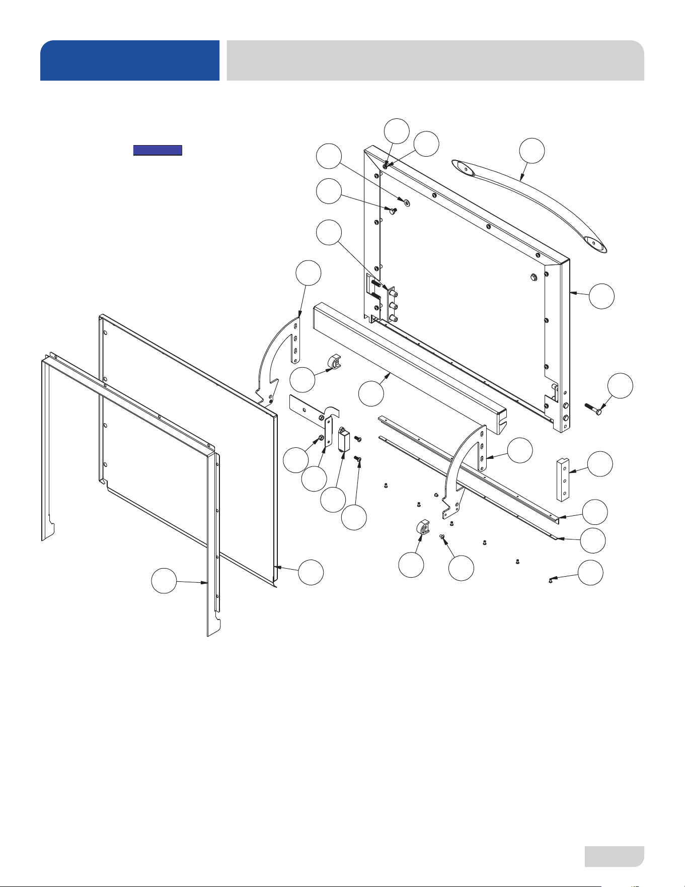
DOOR
PARTS
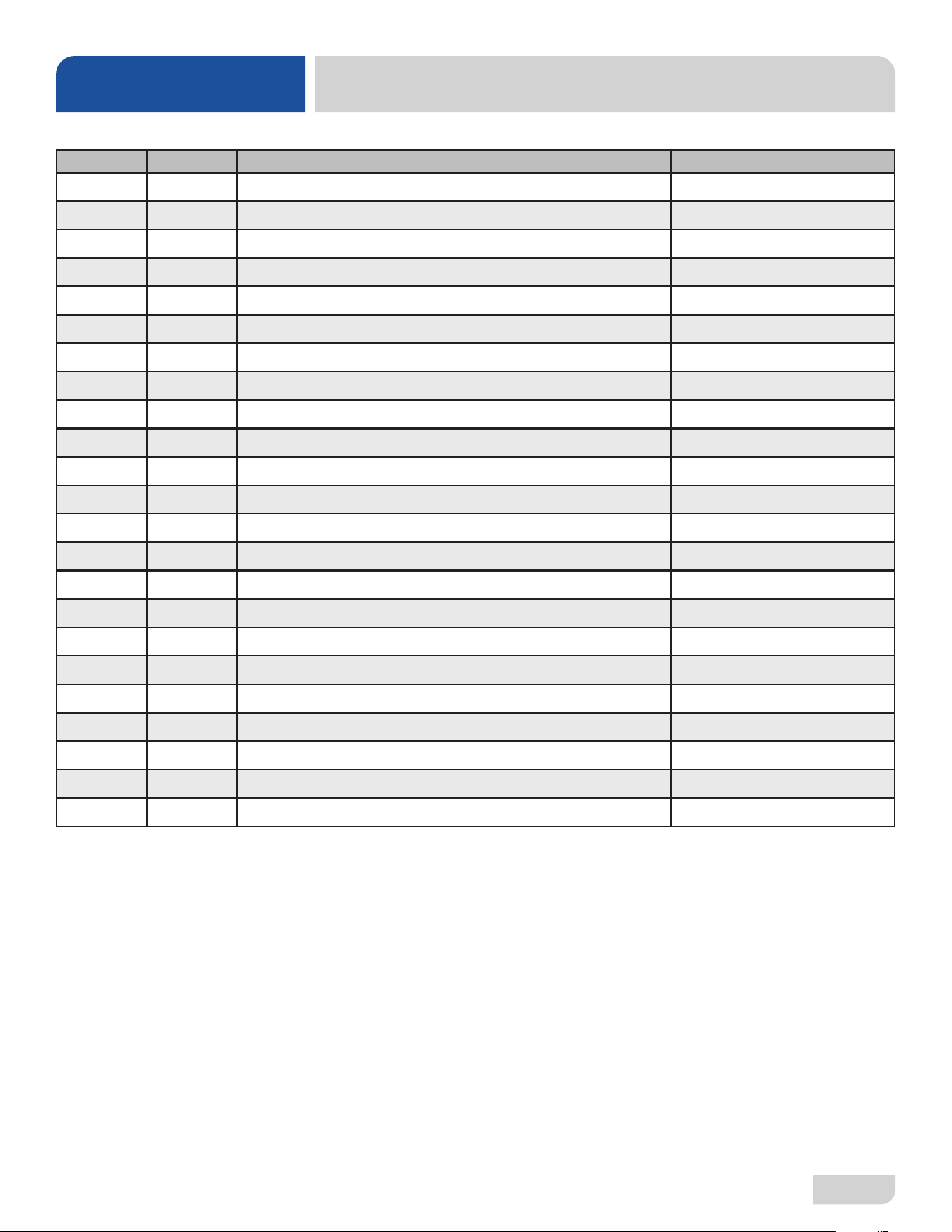
ITEM QTY DESCRIPTION PART NUMBER
1 1 Outer Door Weldment 05700-005-09-56
2 2 Screw, 10-32 x 1/4" 05305-173-01-00
3 2 Bolt, 1/4-20 x 3/8" Hex 05305-274-20-00
4 2 Washer, SS 1/4-20 ID 05311-174-01-00
5 12 Fastener, 10-32 05340-111-58-10
6 1 Door Handle 05700-003-26-62
7 2 Stop, Door Hinge 05700-003-32-55
8 1 Hinge, Left 05700-003-32-71
9 1 Hinge, Right 05700-003-32-72
10 1 Inner Door 05700-003-33-21
11 1 Baffle, Door 05700-003-33-38
12 2 Hinge Spacer 05700-003-33-42
13 2 Retaining Plate 05700-011-44-37
14 1 Channel, Door Seal 05700-003-55-49
15 6 Screw, 1/4-20 x 1 1/2" Hex 05305-274-23-00
16 1 Gasket, Door L 05330-004-36-05
17 1 Gasket Clamp 05700-004-36-56
18 6 Pop Rivet, 1/8" x 3/8" 05320-003-06-98
19 12 Screw, 10-32 x 1/2" Pan Phillips Head 05305-002-32-37
20 2 Locknut, 10-32 with Nylon Insert 05310-373-02-00
21 1 Bracket, Door Magnet 05700-004-52-68
22 1 Magnet, Door 05930-002-88-42
23 2 Screw, 10-32 x 1/2" Pan Phillips Head 05305-011-44-52
07610-004-54-86-P
36
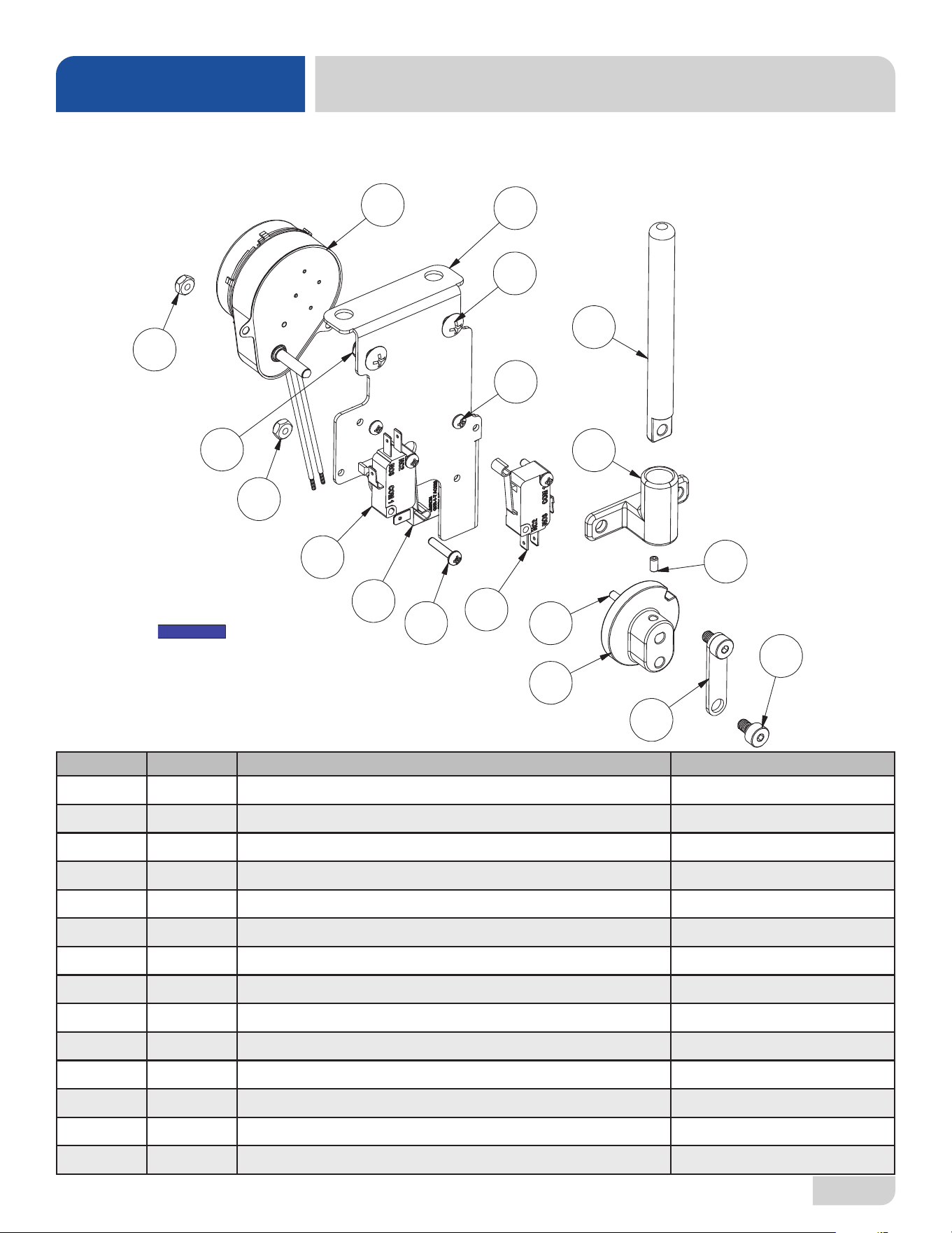
DOOR INTERLOCK
PARTS
Complete Door Interlock Assembly
05700-004-99-58
ITEM QTY DESCRIPTION PART NUMBER
1 6 Screw, 6-32 x 5/8" 05305-011-39-85
2 6 Locknut, 6-32 Hex with Nylon Insert 05310-373-03-00
3 1 Link, Interlock Connector 05700-004-71-37
4 1 Pin, Interlock 05700-004-71-49
5 2 Switch, Interlock 05930-004-71-36
6 1 Synchronous Gearmotor, 6 RPM, 230 V, 60 Hz 06105-004-70-04
7 1 Interlock Guide 05700-004-71-50
8 1 Interlock Cam 05700-004-71-39
9 2 Shoulder Screw, 10-32 05700-004-71-40
10 1 Bracket, Interlock 05700-004-99-63
11 2 Screw, 10-32 x 1/2" 05305-011-39-36
12 2 Locknut, 10-32 with Nylon Insert 05310-373-02-00
13 1 Set Screw, 6-32 x 1/4" 05305-004-71-42
14 1 Relay, 10 A, 220 VAC 05945-004-84-93
2
2
1
5
5
11
4
7
13
3
8
1
1
9
6
10
12
14
Machines with serial numbers before
23D415452 have a dierent interlock.
Click here to open earlier manual.
NOTICE
37
07610-004-54-86-P
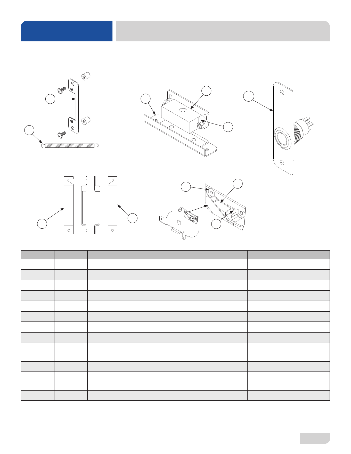
MISCELLANEOUS DOOR COMPONENTS
PARTS
5
Parts are not shown to scale in relation to each other.
4
3
2
1
7
6
8
9
10
11
ITEM QTY DESCRIPTION PART NUMBER
1 1 Switch Mounting Plate Assembly 05700-003-33-54
2 2 Door Spring 05700-003-32-85
3 1 Cover, Left Hinge Weldment 05700-004-36-80
4 1 Cover, Right Hinge Weldment 05700-004-36-81
Hinges secured with Locknut, 1/4-20 Hex with Nylon Insert 05310-374-01-00
5 2 O-ring 05330-003-32-34
6 2 Latch Spring 05700-003-32-32
7 4 Latch Nut 05700-003-32-33
8
2
2
Locknut, 6-32 Hex with Nylon Insert
Screw, 6-32 x 1/4”
05310-373-03-00
05305-171-01-00
9 1 Door Switch 05930-003-31-44
10
1
1
Door Switch Bracket
Door Switch & Bracket Assembly
05700-003-31-43
05700-003-32-21
11 1 Complete Switch Mount Assembly 05700-005-07-45
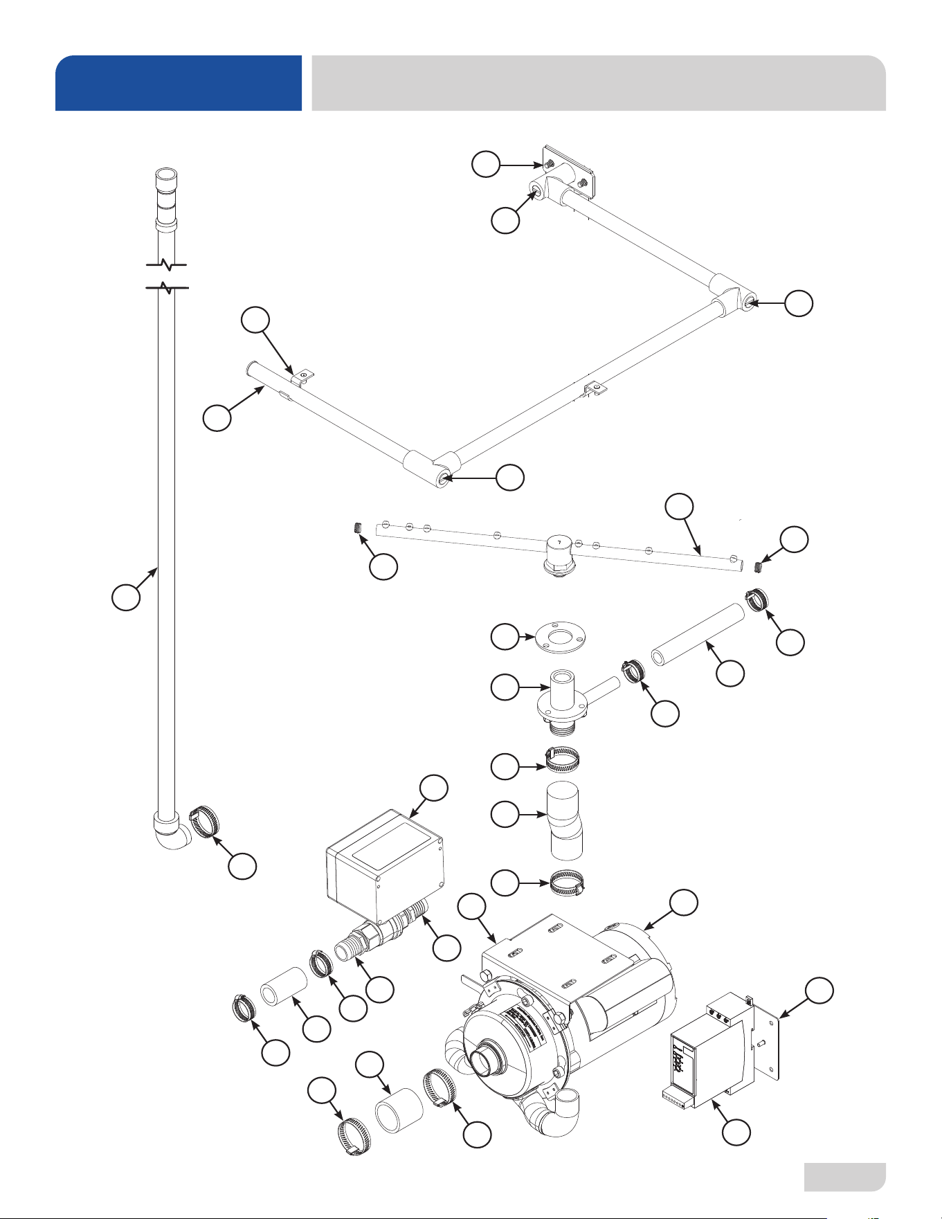
07610-004-54-86-P
38
WASH & MOTOR
PARTS
3
4
5
5
6
5
1
5
5
15
18
8
9
15
15
14
2
10
17
15
11
15
16
16
13
12
13
19
20
15
7
15
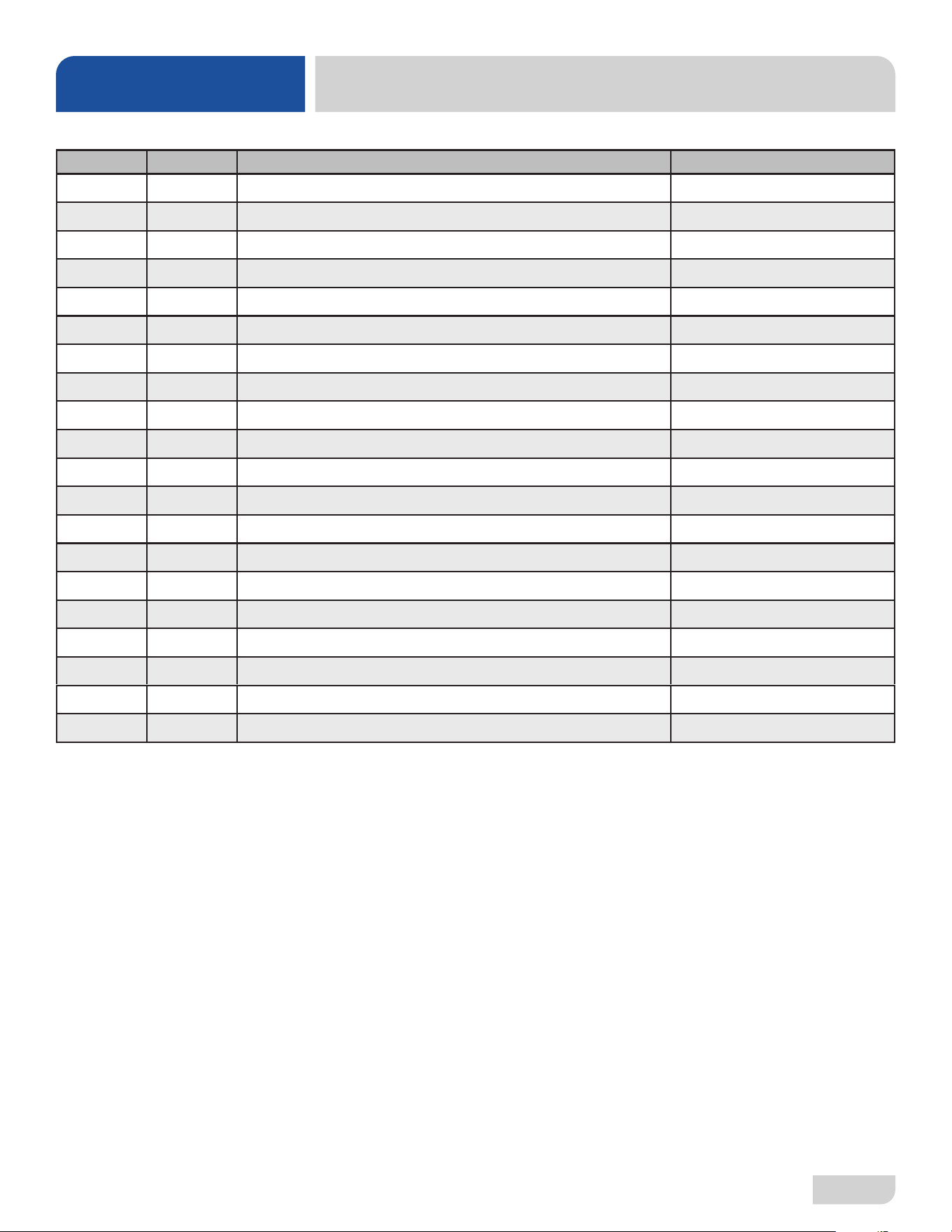
39
07610-004-54-86-P
ITEM QTY DESCRIPTION PART NUMBER
1 1 Wash Arm Assembly 05700-021-39-23
2 1 Motor Support 05700-004-53-96
3 1 Wash Halo 05700-004-42-21
4 2 Pipe Clamp 05700-000-35-06
5 5 Wash Arm End-cap 05700-003-31-59
6 1 Gasket, Manifold 05330-003-75-91
7 1 Hose, 5/8" ID, Blue Silicone 05700-004-53-99
8 1 Gasket, Wash Hub 05330-002-34-77
9 1 Wash Hub 05700-004-43-04
10 1 Pump and Motor 06105-004-50-75
11 1 Hose, 7/8" ID x 8", Blue Silicone 05700-004-43-76
12 1 Hose, Bottom Manifold Pump 05700-001-22-92
13 2 Clamp, 1 1/16" to 2" 04730-719-18-00
14 1 Hose, 1 1/4" ID x 4", Blue Silicone 05700-004-54-00
15 7 Clamp, 13/16" to 1 1/2" 04730-719-06-09
16 2 Hosebarb, 1 3/4" 04730-011-65-86
17 1 Drain Valve Assembly 04730-003-33-64
18 1 Drain Hose 04720-004-32-00
19 1 Bracket, Soft Starter 05700-004-55-94
20 1 Soft Starter 05945-004-55-75
WASH & MOTOR
PARTS
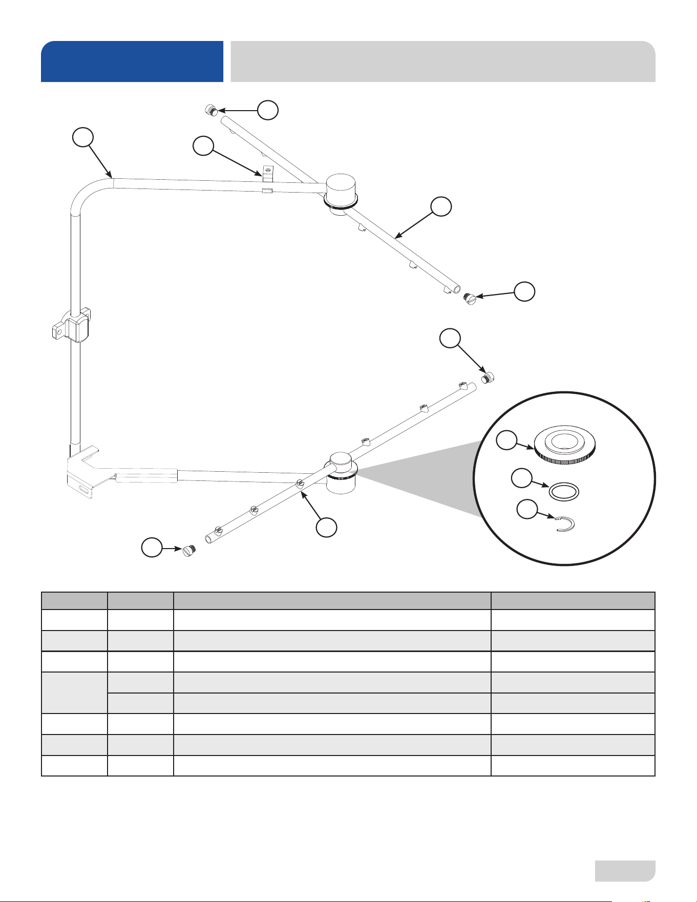
07610-004-54-86-P
40
ITEM QTY DESCRIPTION PART NUMBER
1 1 Complete Rinse Manifold Assembly 05700-004-52-44
2 1 Pipe Clamp 05700-000-35-06
3 4 Rinse Arm End-cap (includes o-ring) 05700-004-34-62
4
2 Complete Rinse Arm Assembly 05700-004-39-39
2 Rinse Arm 05700-004-38-75
5 2 Bearing Assembly, Rinse Arm 05700-004-54-71
6 2 O-ring (included in item #5) 05330-002-60-69
7 2 Retaining Ring 05340-112-01-11
RINSE MANIFOLD
PARTS
1
2
3
4
3
3
3
4
Rinse Arm Bearing Kit
06401-004-57-50
5
7
6
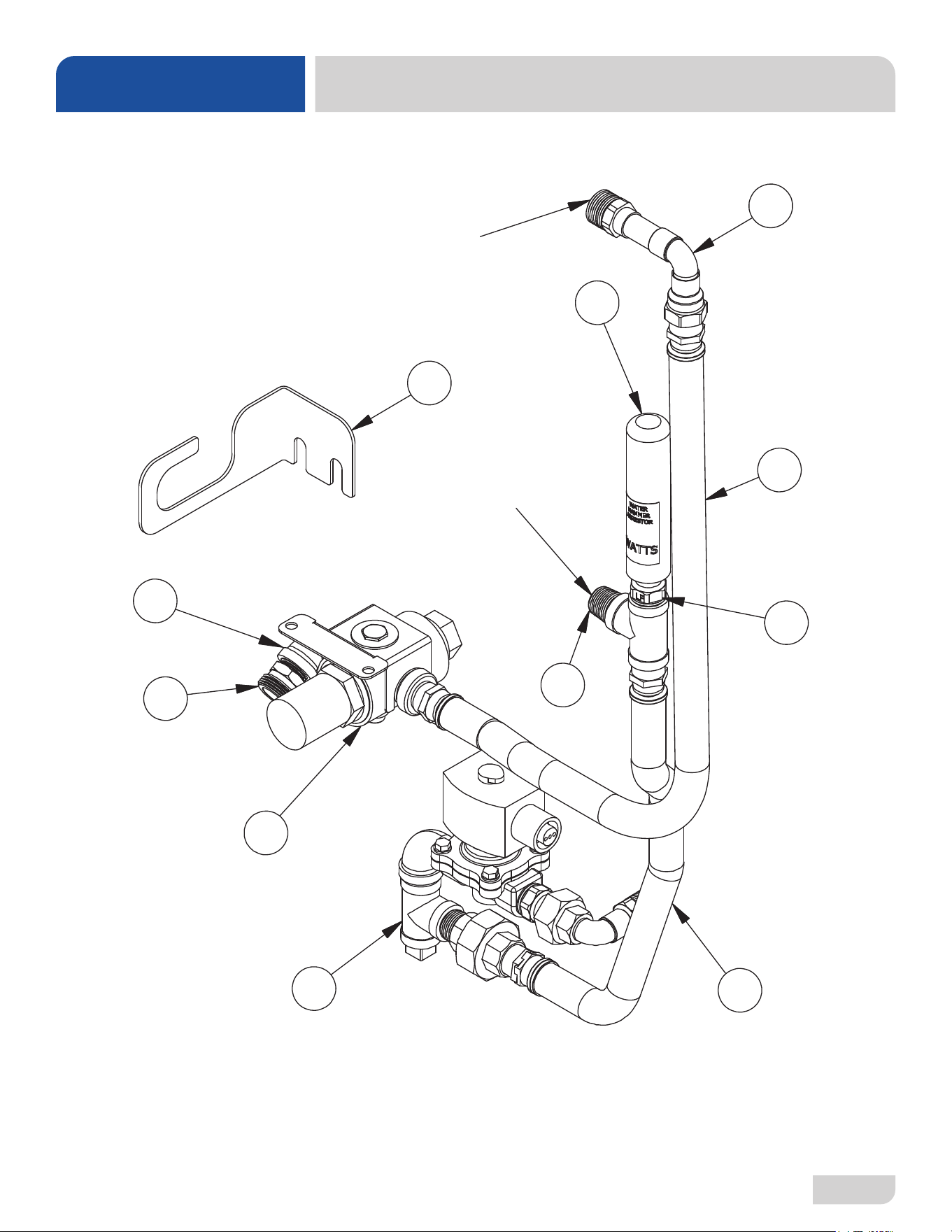
41
07610-004-54-86-P
PLUMBING
PARTS
Complete SEER Plumbing Assembly
05700-004-63-78
3
9
8
7
6
4
5
2
1
10
CONNECTS TO HOT
WATER OUTLET ON
SEER SYSTEM
CONNECTS TO
COLD WATER INLET
ON SEER SYSTEM
11*
*Item not included in part number of complete SEER
plumbing assembly and must be ordered separately.
07610-004-54-86-P
42
PLUMBING
PARTS
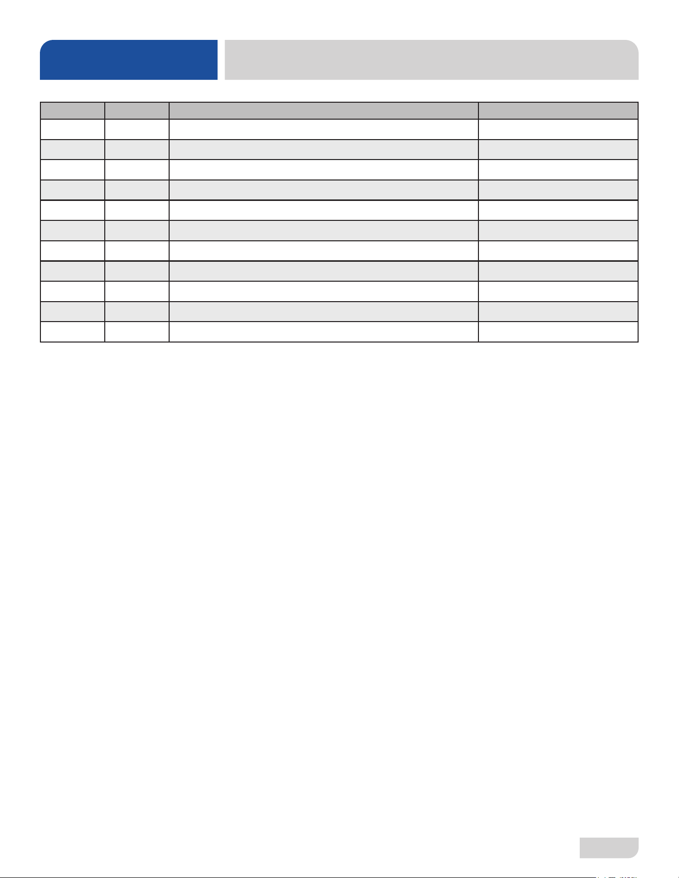
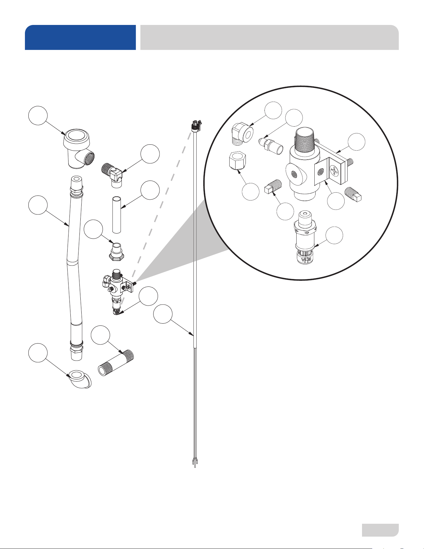
ITEM QTY DESCRIPTION PART NUMBER
1 1 Inlet Plumbing Assembly 05700-004-53-98
2 1 Pressure Regulating Valve Assembly, Dial-set 05700-004-94-35
3 1 Booster Tank Discharge Assembly 05700-004-55-97
4 1 Tee, 1/2" Brass 04730-211-27-00
5 1 Nipple, 1/2" Close Brass 04730-207-15-00
6 1 Water Hammer Arrestor, 1/2" 04730-004-58-56
7 1 SEER Inlet Plumbing Assembly 05700-004-60-46
8 1 Elbow, 90-degree, 1/2" Street Brass 04730-206-08-00
9 1 Adapter, Double Male, 3/4-11.5 x 1/2-14 04720-004-51-55
10 1 Inlet Hose Assembly 05700-004-71-03
11* 1 Bracket, Plumbing Support 05700-004-56-19
*Item not included in part number of complete SEER plumbing assembly and must be ordered separately.
43
07610-004-54-86-P
RINSE PLUMBING
PARTS
1
2
4
5
6
7
3
8
9
8a
8c
8d
8g
8e
8f
8b
Complete Rinse Plumbing Assembly
05700-004-61-32
07610-004-54-86-P
44
RINSE PLUMBING
PARTS
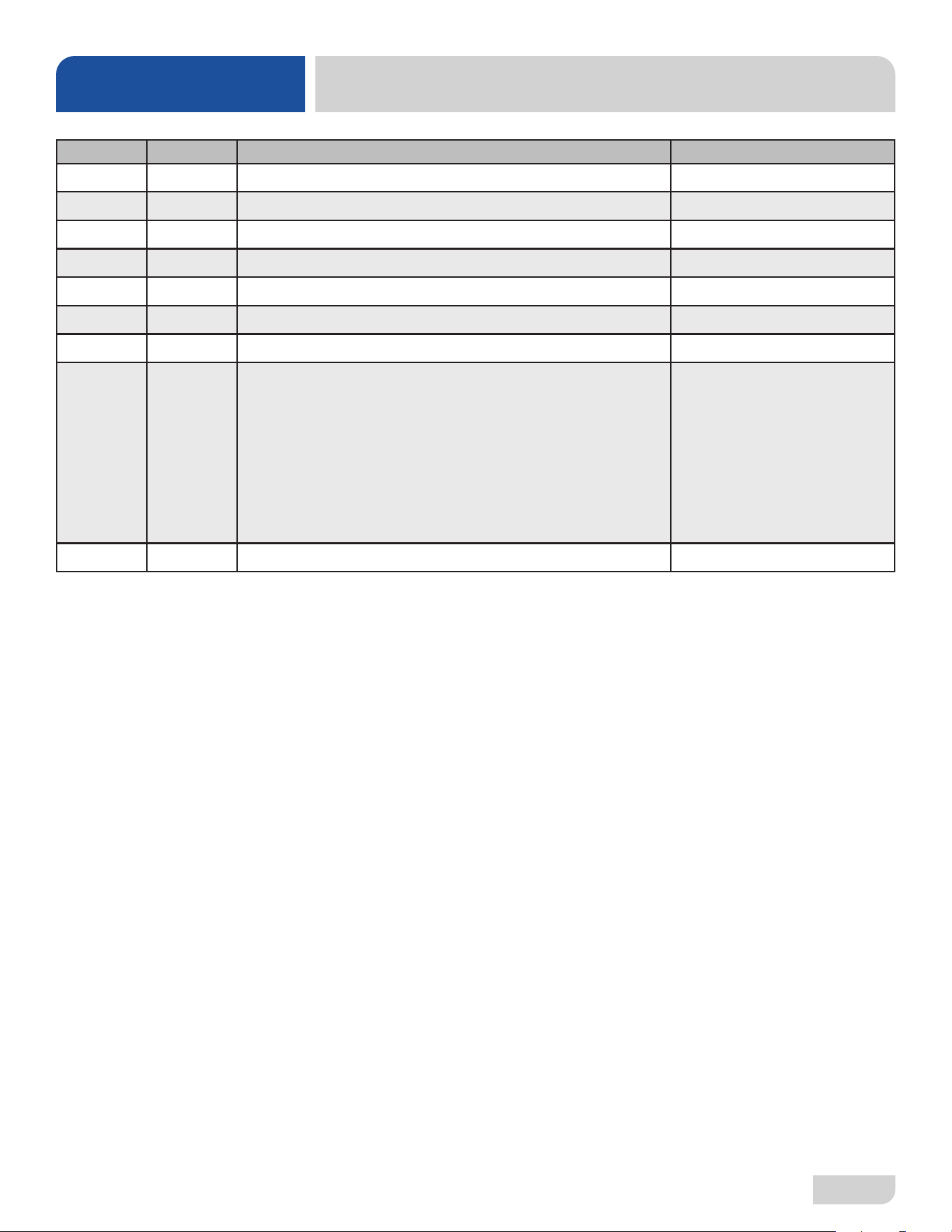
ITEM QTY DESCRIPTION PART NUMBER
1 1 Vacuum Breaker, 1/2" Brass 04820-003-06-13
2 1 Hose, Red, 1/2" ID, 14" 05700-004-99-89
3 1 Nipple, 1/2" x 3", Brass 04730-004-20-10
4 1 Elbow, 1/2", 90-degree, Brass 04730-011-42-96
5 1 Elbow, 90-degree 04730-406-32-01
6 1 Pipe, 3", Copper 05700-001-05-21
7 1 Adapter, 1/2" 04730-002-64-68
8
8a
8b
8c
8d
8e
8f
8g
1
1
1
1
1
1
2
1
Complete Rinse Injector Assembly
Rinse Injector Only
Gasket, Rinse Injector
Check Valve
Fitting, Outlet Elbow
Nut, Tube, 1/8"
Plug, 1/8" Brass
Pressure Transducer
05700-004-43-86
05700-005-12-23
05330-003-75-91
04820-111-51-14
04820-111-51-18
04730-011-59-45
04730-209-07-37
05945-004-84-32
9 1 Harness, Transducer 05700-004-33-62
45
07610-004-54-86-P
SCALE PREVENTION SYSTEM
PARTS
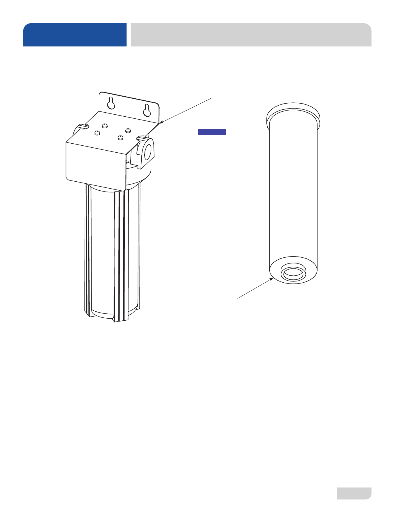
SCALE PREVENTION SYSTEM (SPS) OPTION
Replacement Cartridge
(inspect at least every 6 months)
04730-003-28-04
SPS
04730-003-28-03
Replacement Test Strip
(Not Shown)
06401-003-28-06
Must be installed vertically. The provided
bracket is secured to the wall. Observe
proper inlet/outlet water directions (ow
directions are molded into the top of the
head). Line pressure should be released
before changing cartridges. Machine
should be delimed before installation.
NOTICE
07610-004-54-86-P
46
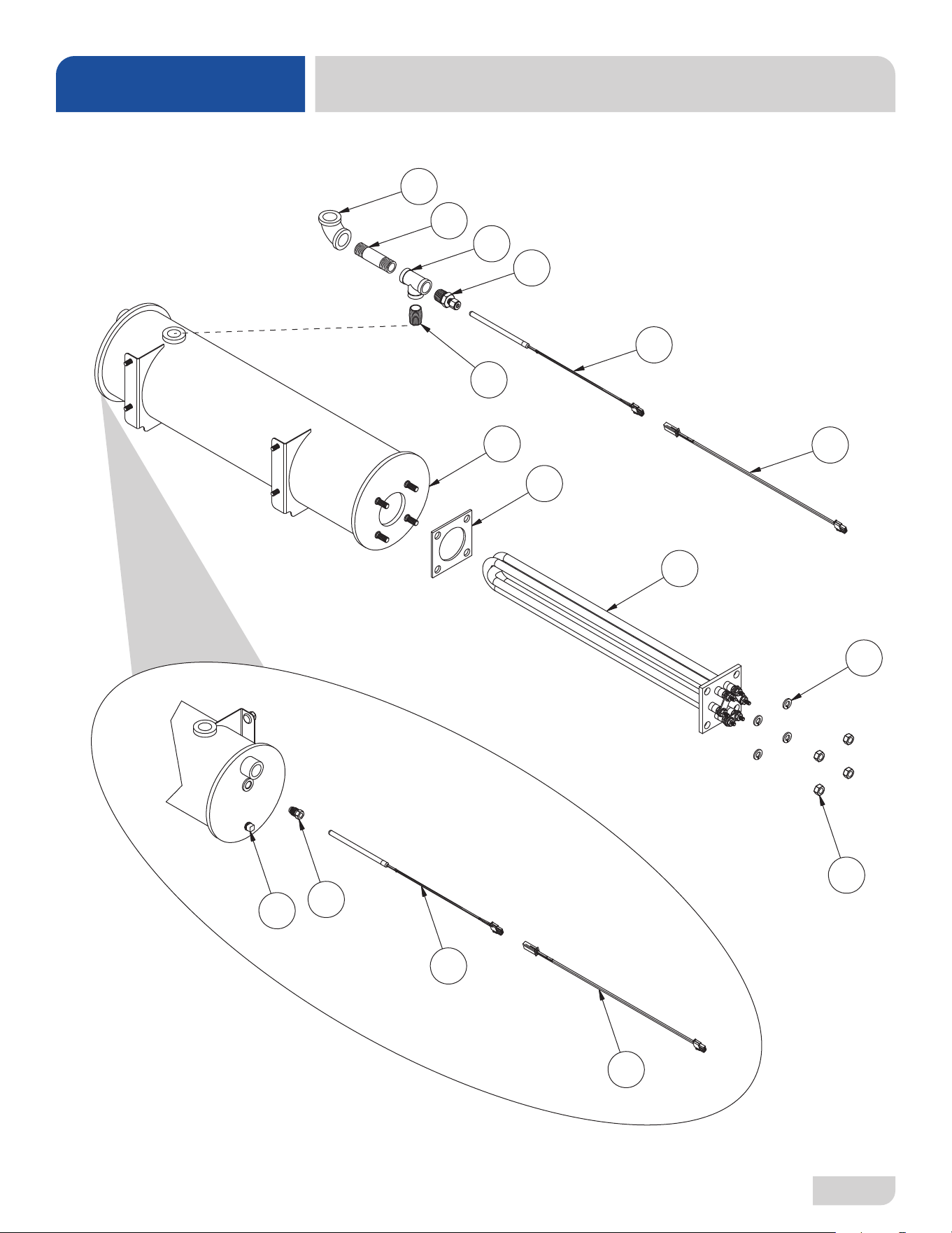
RINSE TANK
PARTS
1
2
3
4
5
6
7
8
9
16
7
11
12
13
10
14
47
07610-004-54-86-P
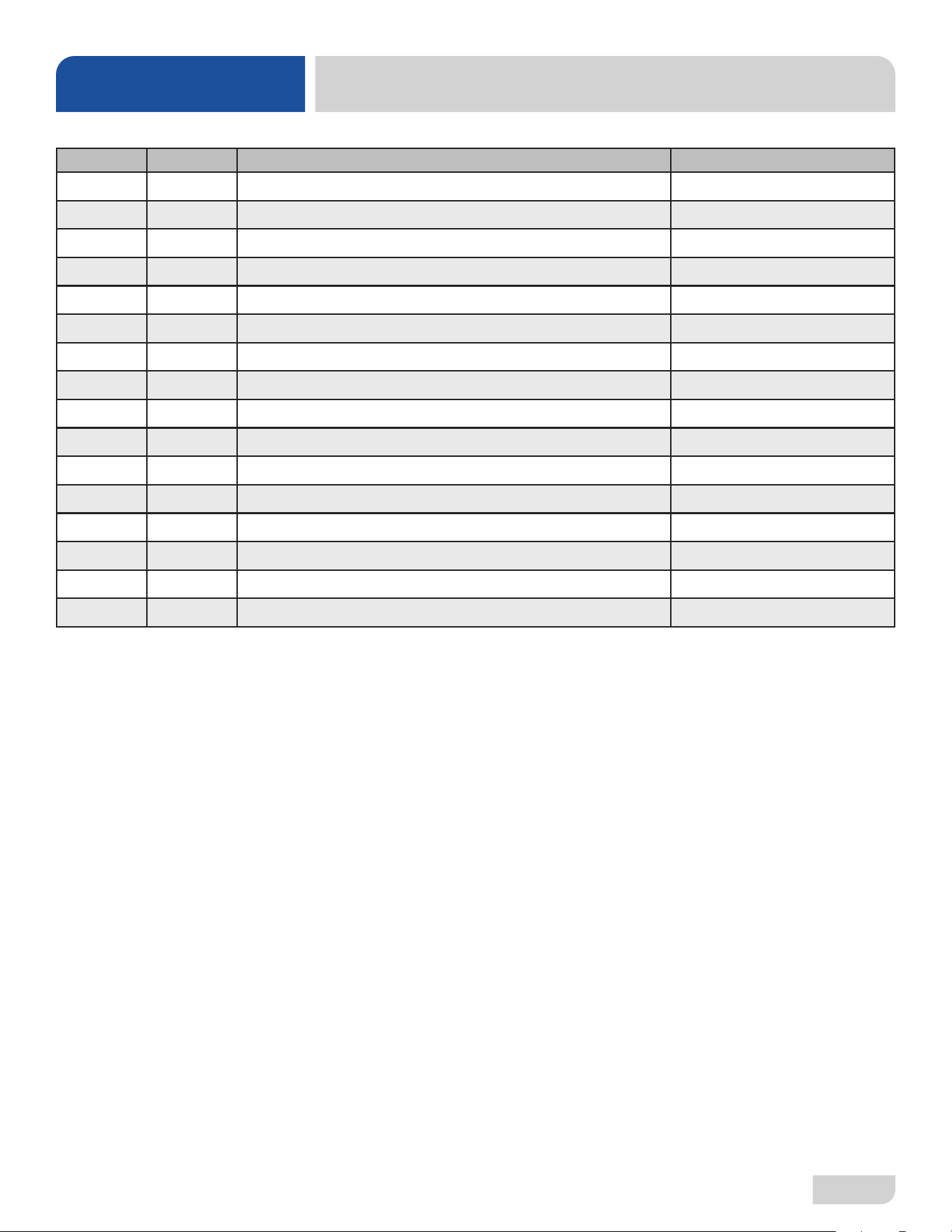
ITEM QTY DESCRIPTION PART NUMBER
1 1 Rinse Tank 05700-004-41-88
2 1 Heater Gasket 05330-011-47-79
3 1 Rinse Heater, 5.45 kW, 208-230 V 04540-004-45-12
4 4 Lockwasher, Split 5/16" 05311-275-01-00
5 4 Nut, Hex 5/16-18 05310-275-01-00
6 2 Cable, Temperature Probe 05700-004-33-23
7 2 Thermistor Probe, 4" with 18" Cable 06685-004-34-58
8 1 Fitting, 1/4", Brass Nut/Sleeve 05310-924-02-05
9 1 Plug, 1/4" Brass 04730-209-01-00
10 1 Nipple, 1/2" Close Brass 04730-207-15-00
11 1 Fitting, 1/2" x 1/4" 05700-004-36-74
12 1 Tee, 1/2" Brass 04730-211-27-00
13 1 Nipple, 1/2" x 3" Brass 04730-004-20-10
14 1 Elbow, 90-degree, 1/2" Brass 04730-011-42-96
15 1 Thermostat, Rinse Tank High-limit (Not Shown) 05930-004-33-12
16 1 Cable, Temperature Probe 05700-004-33-58
RINSE TANK
PARTS
49
07610-004-54-86-P
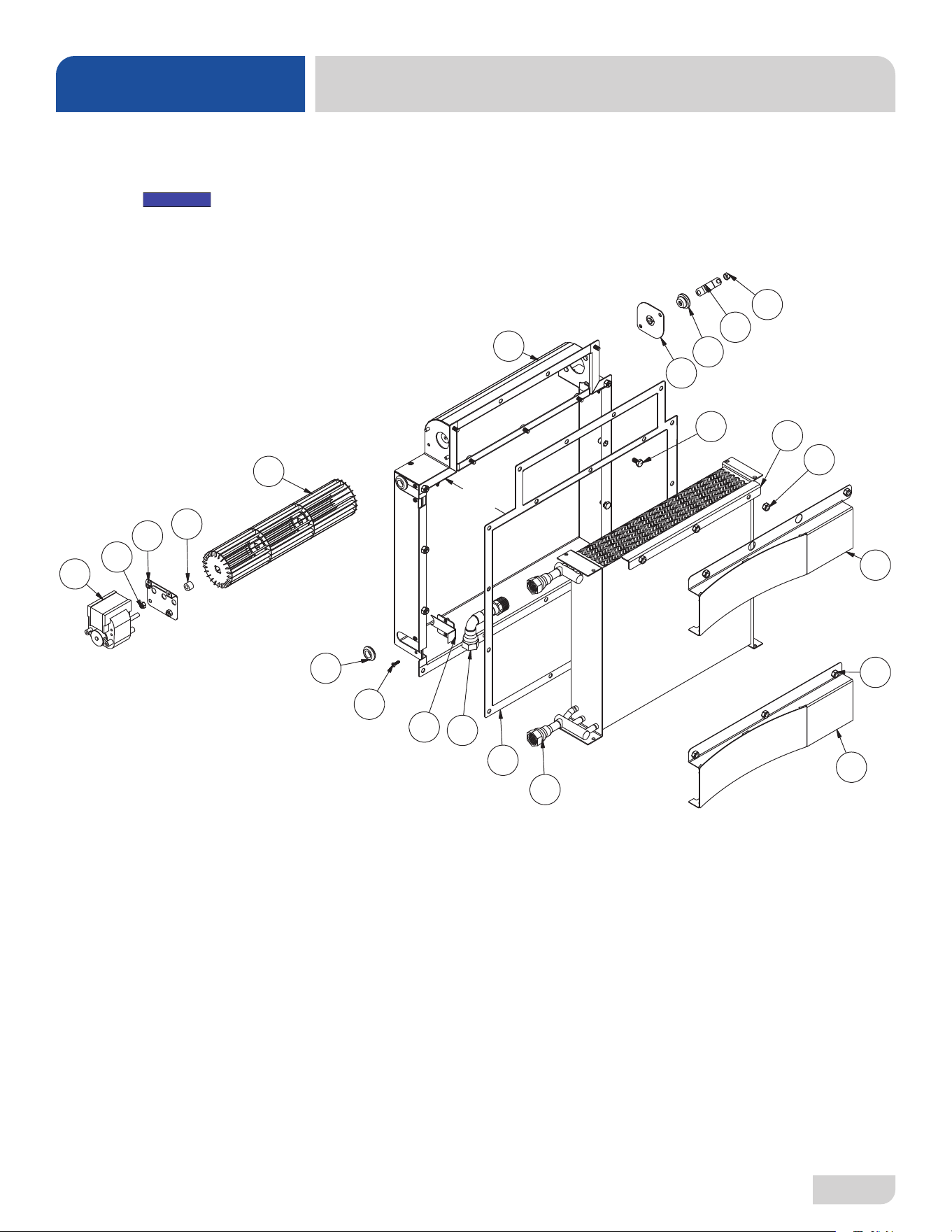
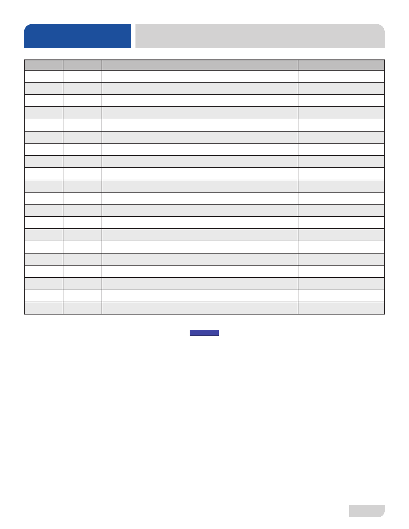
SEER SYSTEM
PARTS
ITEM QTY DESCRIPTION PART NUMBER
1 1 Motor, Fan 05999-004-63-31
2 1 Wheel, Blower 05999-004-59-13
3 1 Bracket, Bearing Boot 05700-004-50-94
4 1 Bushing and Housing Assembly 03120-004-50-88
5 5 Locknut, 10-24 Hex with Nylon Insert 05310-373-01-00
6 1 Bracket, Motor Adjustment 05700-004-58-81
7 2 Grommet, Push-in, 3/4" ID 05330-004-59-14
8 2 Bracket, Enclosure Filler Plate 05700-004-58-93
9 1 Diversion Plate 05700-004-59-04
10 1 Upper Shield 05700-004-58-98
11 1 Heat Exchanger, 3/8" Tubes 04420-004-58-96
12 12 Locknut, 1/4-20 Hex with Nylon Insert 05310-374-01-00
13 8 Screw, 6-32 x 1/2" 05305-004-23-63
14 1 Condenser Assembly 05700-004-58-94
15 2 Bolt, 1/4-20 x 1/2" 05305-274-02-00
16 1 Plumbing, SEER Inlet 05700-004-60-46
17 1 Bracket, Bearing Hard Stop 05700-004-67-53
18 1 Lower Shield 05700-004-63-04
19 1 Spacer, 1/2" OD 1/4" ID Nylon, Black 03120-004-95-13
20 1 Gasket, Exchanger to Tub 05330-004-59-16
NOTICE
Machines with serial numbers
before 19G376587 have an older
version of the SEER System.
Click here to open earlier manual.
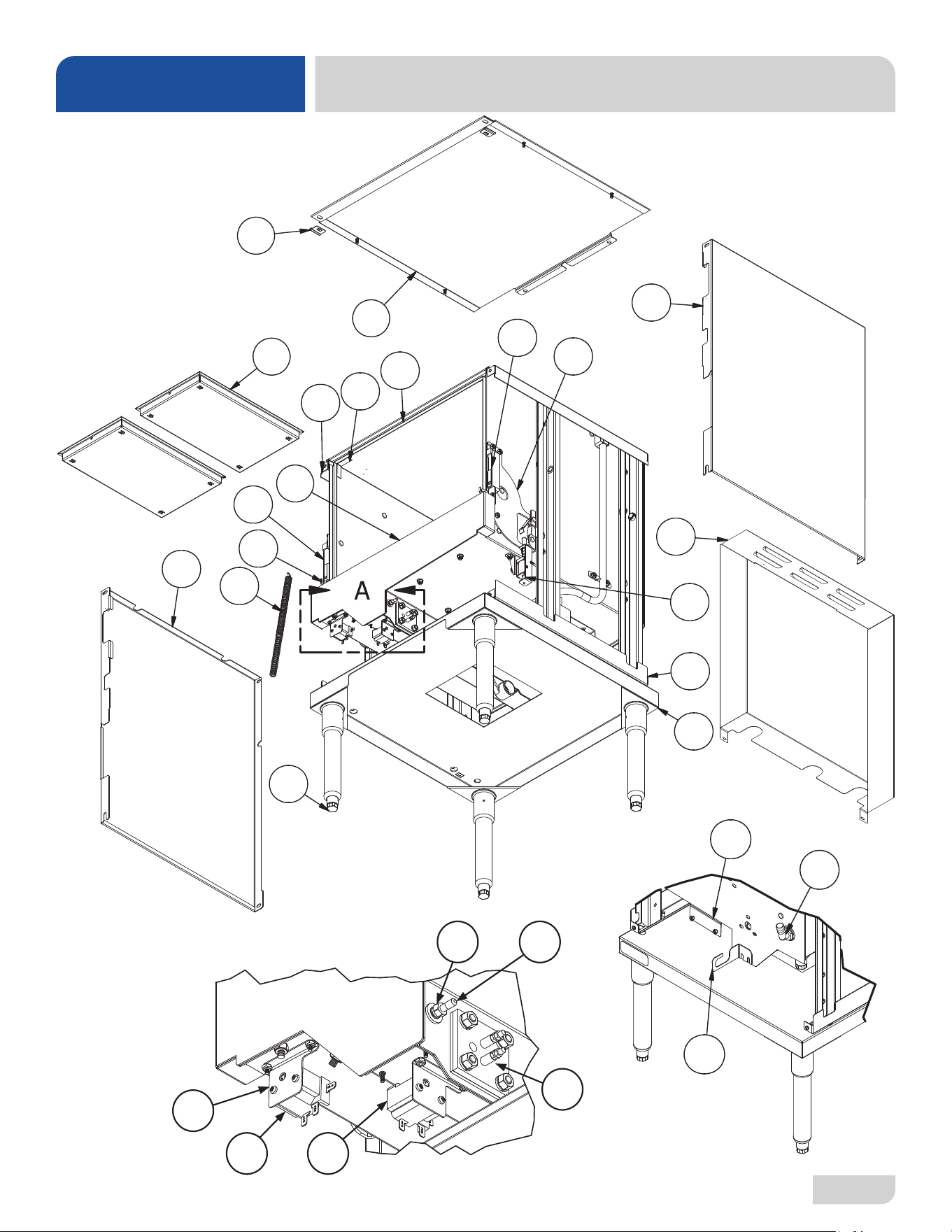
07610-004-54-86-P
50
TUB & FRAME
PARTS
1
2
4
3
6
5
26
27
25
7
8
9
10
11
12
22
23
24
19
21
20
FRONT
BACK
DETAIL A
16 17
18
1514
13
28
51
07610-004-54-86-P
ITEM QTY DESCRIPTION PART NUMBER
1 2 Plug, Shroud 05700-003-32-50
2 1 Top Shroud 05700-003-37-06
3 2 Strainer 05700-004-09-43
4 1 Tub Back 05700-004-55-03
5 2 Channel Back 05700-004-04-24
6 1 Left Frame Assembly 05700-004-52-33
7 1 Tub Front 05700-004-51-79
8 1 Hinge Cover, Left 05700-002-18-41
9 1 Hinge Stop, Left 05700-003-32-61
10 2 Door Spring 05700-003-32-85
11 1 Left Shroud 05700-004-55-00
12 4 Foot, Adjustable 05340-108-01-03
13 2 Bracket, High-limit 05700-004-36-37
14 1 Thermostat, High-limit 05930-004-33-12
15 1 Thermostat, High-limit with Compression Fitting 05930-004-33-15
16 2 Fitting, Brass Sleeve 05310-924-02-05
17 1 Thermistor Probe, 4" with 18" Cable 06685-004-34-58
18
1
1
Wash Heater, 4 kW
Gasket, Wash Heater (Not Shown)
04540-003-99-44
05330-011-61-34
19 1 Bracket, Terminal Box 05700-004-55-90
20 1 Bracket, Rinse Tank Plumbing Support 05700-004-56-19
21 1 Fitting, Bulkhead to 1/2" Hosebarb 04730-011-45-21
22 1 Stand Assembly 05700-004-54-13
23 1 Right Frame Assembly 05700-004-52-32
24 1 Door Interlock Assembly See Door Interlock page.
25 1 Hinge Stop, Right 05700-003-32-60
26 1 Hinge Cover, Right 05700-004-22-66
27 1 Right Shroud 05700-004-52-49
28 1 Rear Dress Panel 05700-004-58-13
TUB & FRAME
PARTS
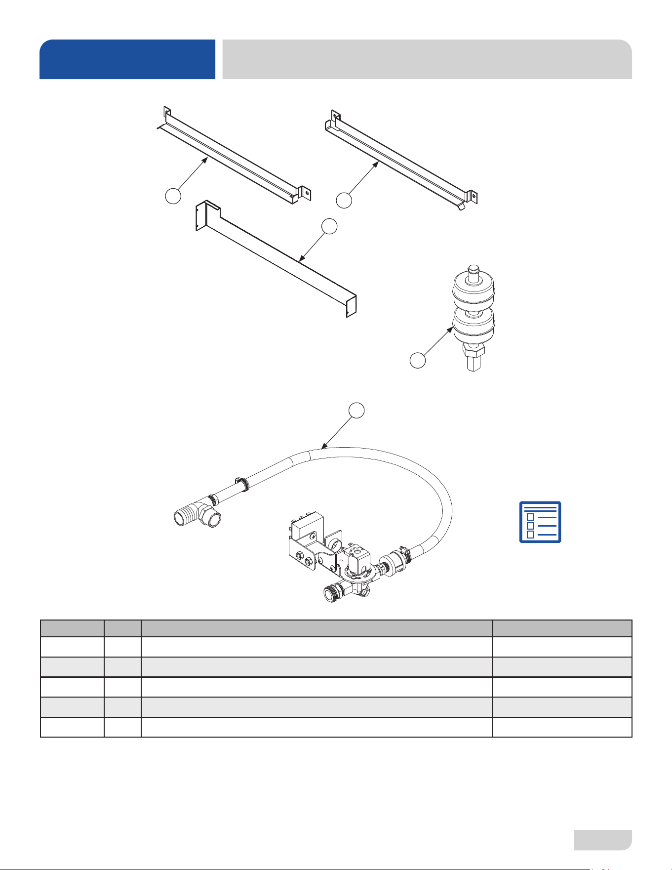
07610-004-54-86-P
52
MISCELLANEOUS PARTS
PARTS
1
2
3
5
ITEM QTY DESCRIPTION PART NUMBER
1 1 Rail, Left Rack 05700-031-37-89
2 1 Rail, Right Rack 05700-031-37-88
3 1 Splash Shield 05700-003-33-51
4 1 Dual Float Switch 06680-004-48-53
5 1 Drain Water Tempering Kit 06401-004-59-11
Parts are not shown to scale in relation to each other.
4
Drain Water Tempering
Kit Install Instructions