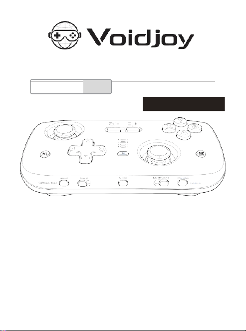
SkyLark S1 Pro Portable Controller
User Manual
* This product includes anenhanced grip attachment.
FirmwareUpdate
Voidjoycontinually improves the software for this accessory to provide the latest features.We
recommendupdatingthe Firmwareor app as soonas a KeyLinkerupdatenotification is
available.
Fordetails,see"FirmwareUpdate"on page23or thesupportinformationon theofficialwebsite.
DearCustomer
Thankyou for purchasing this product.
For best performance and safe operation, read this manual carefully before connecting,
operating, or adjusting this product. Keep this manual for future reference.
Multi-platform
See page 4
Warranty Card Included
GC-P01


Contents
Safety Precautions................................................................................................. 2
About Bluetooth..................................................................................................... 3
Compatibility..........................................................................................................4
Preparation
Accessory List
...............................................................................................
11
Button Layout................................................................................................11
[Preparation] Installation.................................................................................13
Installing/Removing the Enhanced Grip
............................................................
13
Linear Trigger/Quick Trigger Switching.............................................................14
Charging/Checking Remaining Battery Power...................................................15
Controller Power On/Off and USB/2.4 GHz/Bluetooth Connection
.......................
16
Simple Pairing with Switch Console Using One-Cable Pairing.............................18
Pairing with a Switch 2 Console and Using the Wake Function........................... 18
Operation
Basic Operations......................................................................................... 19
·
Selecting the Connection Mode
..................................................................
19
·
TURBO Settings (Rapid Fire/Auto Rapid Fire)
............................................
19
·
Recording Macros with the ML/MR Expansion Buttons
..............................
20
·
Mapping Buttons and Forced Motion Control with the ML/MR Expansion
Buttons
...........................................................................................................
20
· Switch/PlayStation 3 Connection Channel Number Indicator........................ 21
Changing Controller Settings in the App (Advanced Settings)............................. 22
Other
Resetting the Controller (RESET).................................................................... 23
Gyroscope (Motion Control) Calibration............................................................23
About Firmware Update..................................................................................23
Copyright and Trademarks
..............................................................................
24
Specifications................................................................................................25
Warranty Card/After-Sales Terms
....................................................................
27
Removing the Battery When Disposing of This Product
......................................
29
2
To prevent damage, avoid the following:
Operating Precautions
When connecting to a computer or other smart device, use the included USB-C charging cable. If
using another USB-C-compatible cable, first confirm that it supports USB 2.0 data transfer; otherwise,
the device may not recognize the Controller.
Intended Use: This Controller is intended for standard consumer use only. Do not use
the Controller near devices or in environments where radio-frequency interference
may occur, such as airports, hospitals, or laboratories. If the connected device
supports wired operation, use a wired connection instead.
Safety
Precautions -
Please Read
Carefully
■ Do not use flammable sprays, insecticides, or similar aerosol products near the Controller.
■ Keep water, juice, and other liquids away from the Controller. Liquid exposure may cause button
malfunction or damage.
■ Do not connect or disconnect the USB cable with wet hands.
■ Keep foreign objects out of the Controller's USB-C port.
■ Do not use the Controller in humid or high-temperature locations, such as bathrooms.
■ Do not place other objects on the Controller or cover it with cloth while charging.
■ Do not use the Controller where it may fall, in dusty locations such as beaches, or near magnetic
fields.
■ Do not place the Controller on heat exhaust vents, computer cases, or other heat-generating
equipment.
■ Charge the Controller before first use or after an extended period of non-use.
■ The Controller battery may become warm during use or charging. This is normal.
■ Operating instructions and safety precautions may be updated. For the latest information, check
the support website or the latest help content in the app.
■ Do not use excessive force during operation. Excessive force may cause hand fatigue and
accelerate button wear.
■ If your wrists or fingers become sore during use, adjust your posture and reduce the amount of
force used, or stop using the Controller for a while.
■ If the grip or any other part that directly contacts your skin causes discomfort, stop using the
Controller. Continued use may cause a
rash or other allergic reaction.

About Bluetooth®
3
Voidjoyisnotresponsibleforanydataand/orinformationleakagethatoccursduringwireless
transmission.
Frequency Band Used
●
The Controller uses the 2.4 GHz frequency band.
Controller Certification
●
This Controller complies with applicable frequency limits and wireless certification
requirements.
Restrictions on Use
●
Wirelesstransmission and/or useis not guaranteedwith all Bluetooth® devices.
●
All devices mustcomply with standards establishedby Bluetooth SIG,Inc.
●
Depending on thedevicespecificationsand settings,connection may not be possible, orcertain
operations maydiffer.
●
TheControllersupportsBluetooth® security features;however,dependingon theusage
environmentand/or settings, including OTA Firmwareupdates,thissecurity may not besufficient.
Usecautionwhen transmitting datawirelesslyto theController.
OperatingRange
●
The Controller has amaximumoperatingrange of10 meters(33 feet).
●
The rangemaybereduceddepending on theenvironment,obstacles,or interference.
Interference from Other Devices
●
IftheController isplacedtooclosetootherBluetooth® devices ordevices usingthe2.4GHzband,suchas
Wi-Firoutersorcordless phones,radio-waveinterferencemayaffect operation.Symptoms mayincludeinput
delay,repeatedinputs,or noresponse.
●
Ifradiowavesfrom anearbybasestation or similar sourceare toostrong, the Controller may notoperate
correctly.
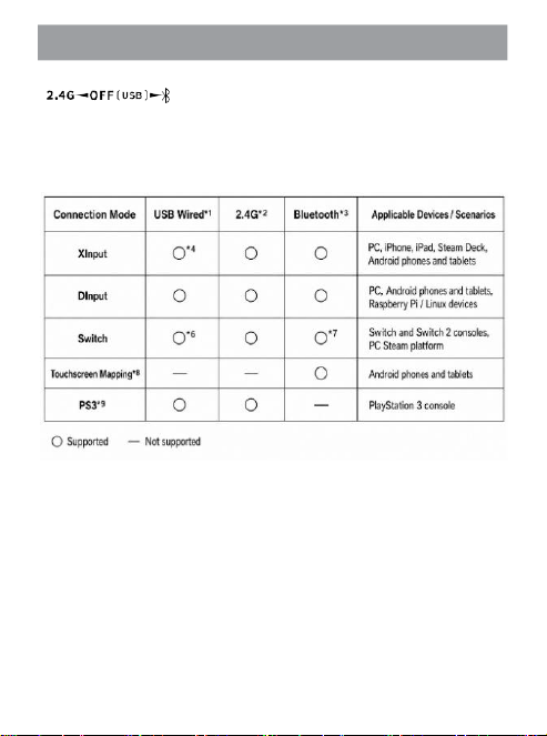
Compatibility Overview
4
This Controllersupportsthreeconnectionmethods:
(Selectthe operatingstate withthe3-positionslideswitch.)
2.4GHz:ConnectstotheincludedReceiver.Pairingis required forfirst-time use.
USB:EnabledwhentheController isconnectedto a compatible devicewhilepowered off.
Bluetooth: Selecta protocolmodeto connecttocompatibleBluetooth-enableddevices.
Controller compatibilityunderdifferent connectionstates (○: Available, -: Notavailable)
*1 USB wired mode supports automatic connection mode detection and selection, as well as manual
mode.
*2 Controller switching requires two Controllers connected to the same 2.4 GHz Receiver.
*3 Bluetooth mode supports switching between two saved devices. It does not support simultaneous
connection to two devices.
*4 Forced Motion Control is not supported during wired connection to help prevent drops or tip-over
damage caused by cable drag.
*5 This product does not support Amiibo peripheral sensing or HD Rumble. Standard Vibration is
supported.
*6 During wired connection, simple Bluetooth Pairing with a Switch console through a cable is
supported.
*7 Switch Bluetooth mode supports the Switch 2 console wake function. See page 18 for details.
*8 Some older MTK processors do not support touchscreen mapping.
*9 PS3 mode supports Vibration and multiple-Controller connection, but does not support Sixaxis
Motion Control.
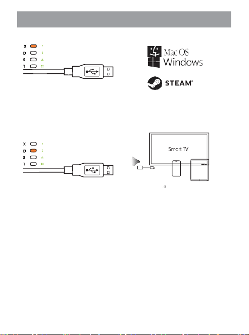
USB Mode Compatibility
5
TheUSBportonthisControllersupportsautomaticdevicerecognitionandmanualmodeselection:
USBwiredconnectiontoaPCinXInputmode
●
SupportsWindowsXP/7/10/11 and macOScomputers usingthe Xbox360 XInput protocol.
●
Supports switching between optical Linear Trigger and Quick Trigger modes.
●
While connected, press and hold the Mode button to switch between XInput and DInput modes.
●
To help prevent accidents caused by cable drag, Motion Control is disabled in wired mode. Use 2.4 GHz or
Bluetooth mode if Motion Control is required.
●
Supports standard dual-rotor vibration. Vibration behavior may vary by system.
●
Supports enhanced settings, including joystick sensitivity, dead zone, button remapping, rapid fire, and macro
recording.
USBwiredconnectiontocomputers,phones,tablets,smartTVs,andotherdevicesinDInputmode
●
When connectingto a phone, tablet, or similar device, a C-to-Ccableor OTG adapter cableis required(soldseparately).
●
Vibration support on Android devices depends on the device manufacturer standard.
●
DInput and XInput modes can be switched while connected by pressing and holding the MODE button.
●
To help prevent accidents caused by cable drag, Motion Control is disabled in wired mode. Use 2.4 GHz or
Bluetooth mode if Motion Control is required.
●
If a game is designed to support touchscreen operation only and does not support Controller input, this mode
cannot be used to control that game. Use Bluetooth touchscreen mapping mode for setup and operation.
●
Supports enhanced settings, including joystick sensitivity, dead zone, button remapping, rapid fire, and macro
recording.
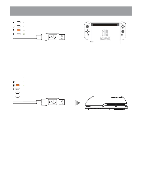
USB Mode Compatibility
6
USBwiredconnectiontoSwitch/SwitchLite/Switch2inProControllermode
●
Switch wake is not supported in2.4 GHzmode.Use Bluetoothmode (recommended).
●
Supportssimple one-cable BluetoothPairing. Bluetooth-mode Pairingis completed whenthecable is connected.
●
SupportsMotionControl and vibration, but does notsupportHD Rumbleor Amiiboperipheralsensing.
●
SupportsPro Controller channelnumber indication,shown withgreen indicators. Seepage21 for details.
●
Supportsenhanced Pro Controller settings including joysticksensitivity/deadzone, button remapping, rapid fire, and
macrorecording.
* In normal indicator status, this shows the Controller channel number assigned by the PS3 console.
USBwiredconnectiontoPlayStation3inDualShock3Controllermode
●
Supportsvibration and LinearTriggerfunctions, butdoes not support Sixaxis.
●
SupportsControllerchannelnumberindication, shownby orangeindicators. See page21 for details.
●
Under standard conditions,up to 2 wiredControllers can be connected toa PS3 consoleat the sametime.
MoreControllersrequirea compatible USB hub.
●
Supportsenhancedsettings,including joysticksensitivity,dead zone, button remapping,rapidfire,and
macrorecording.
●
Thisproduct doesnotprovidefunctions otherthanthosedescribedin this manual.Somesoftwarethat can
beused on a PlayStation3 consolemay not be compatible with thisproduct.
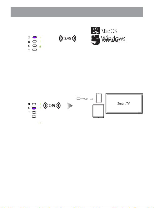
2.4 GHz Mode Compatibility
7
Theincluded2.4GHzReceiversupportsfourmodesandautomaticdevicedetection:
2.4GHzwirelessconnectiontoaPCinXInputmode
●
Supports Windows10/11 and macOS computers using theXboxOne XInput protocol.
●
Supports switchingbetweenopticalLinear TriggerandQuickTrigger modes.
●
Whileconnected, press and hold the MODE buttonto switch between XInput andDInput modes.
●
Supports Forced MotionControl, where Motion Control replaces right joystick input.See page 20for details.
●
Supports standard dual-rotorvibration. Vibration behaviormay vary by system.
●
TwoControllersconnectedto the same2.4 GHz Receivercan exchange control.
●
Supports enhanced settings, includingjoystick sensitivity,dead zone,button remapping,rapid fire,and macro recording.
2.4GHzwirelessconnectiontocomputers,phones,tablets,smartTVs,andotherdevicesinDInputmode
●
Forphones,tablets,and similar devices,the 2.4GHz Receiverrequiresan OTG adaptercable(soldseparately).
●
Vibrationsupporton Androiddevices dependson the device manufacturerstandard.
●
DInput and XInputmodes can be switched whileconnectedby pressing andholdingthe MODE button.
●
Supports Forced MotionControl, where Motion Control replaces right joystick input.See page 20 fordetails.
●
Ifa game is designed tosupporttouchscreenoperation onlyand doesnot support Controller input, this modecannot be
used to control that game.Use Bluetoothtouchscreen mappingmodefor setupandoperation.
●
TwoControllersconnectedto the same2.4 GHz Receivercan exchange control.
●
Supports enhanced settings, includingjoysticksensitivity,dead zone,buttonremapping,rapid fire,and macro recording.
2.4 GHz Mode Compatibility
8
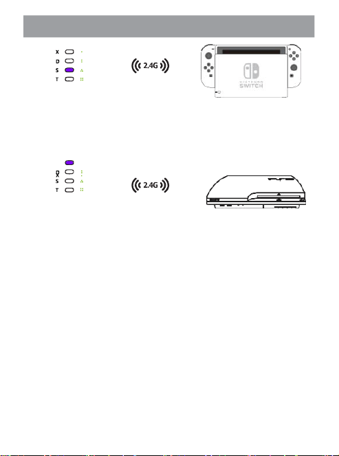
2.4GHzwirelessconnectiontoSwitch/SwitchLite/Switch2inProControllermode
●
Switch wake is not supportedin 2.4 GHz mode.Use Bluetoothmode.
●
Supports Motion Control and vibration, but doesnot support HD Rumble or Amiiboperipheral sensing.
●
Supports Controller channelnumberindication,shownby green indicators.See page 21fordetails.
●
TwoControllersconnectedto the same2.4 GHz Receivercan exchange control.
●
Supports enhanced settings, includingjoysticksensitivity,dead zone,buttonremapping,rapid fire,and macro recording.
* In normal indication status, this is shown as the Controller channel number assigned by the PS3 console.
2.4GHzwirelessconnectiontoPlayStation3inDualShock3Controllermode
●
Supports vibration and Linear Trigger functions, but does not support Sixaxis.
●
Supports Controller channel number indication, shown by purple indicators. See page 21 for details.
●
Under standard conditions, two Receivers can be connected to a PS3 console to connect four Controllers. More
Controllers require a compatible USB hub.
●
Two Controllers connected to the same 2.4 GHz Receiver can exchange control.
●
Supports enhanced settings, including joystick sensitivity, dead zone, button remapping, rapid fire, and macro
recording.
●
This product does not provide functions other than those describedin this manual. Some software that can be used
on a PlayStation 3 console may not be compatible with this product.
Bluetooth Mode Compatibility
9
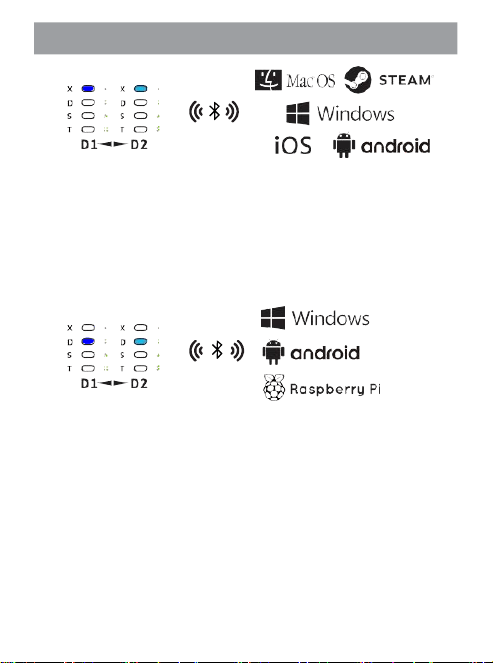
Xmode:ConnectsbyBluetoothtocomputers,Androiddevices,iOSdevices,andotherdevicesasanXbox-
styleController.
●
Supports Windows 8/10/11 and macOS computers using the Xbox One XInputprotocol.
●
Supports compatible app games and applications on Android 5.1.1 orlater that support Xbox Controllers.
●
Supports iPhone/iPad devicesrunning iOS 13.2or later.
●
In XInputmode, the optical Linear Trigger function is active and can be used for racing games and other games that require precise
control. It cannot be used to connect to an Xbox console.
●
Supports Forced Motion Control, where Motion Control replaces right joystickinput. See page 20 for details.
●
Supports standard dual-rotor vibration. Vibrationbehavior may vary bysystem.
●
Supports enhanced settings, includingjoystick sensitivity, dead zone, buttonremapping, rapid fire, and macro recording.
Dmode:ConnectsbyBluetoothtovariousdevicesasageneralController(DInputprotocol).
●
Supports emulator game control on Windows8/10/11 and PC games on Windows XP/Vista/7 systems.
●
Supports Controller connection to Raspberry Pi and other emulation game systems whenthe device supportsBluetooth connection.
●
Supports Bluetooth Controller connection with Android phones, Android tablets, and smart TVs.
●
Supports Forced Motion Control, where Motion Control replaces right joystickinput. See page 20 for details.
●
Supports pressure-sensitiveoperation of the Linear Triggerbuttons. Linear Trigger functionality may beunavailable depending on
system compatibility.
●
Supports standard dual-rotor Vibration. Vibration may be unavailable depending on system compatibility.
●
Supports enhanced settings, includingjoystick sensitivity, dead zone, buttonremapping, rapid fire, and macro recording.
Bluetooth Mode Compatibility
10
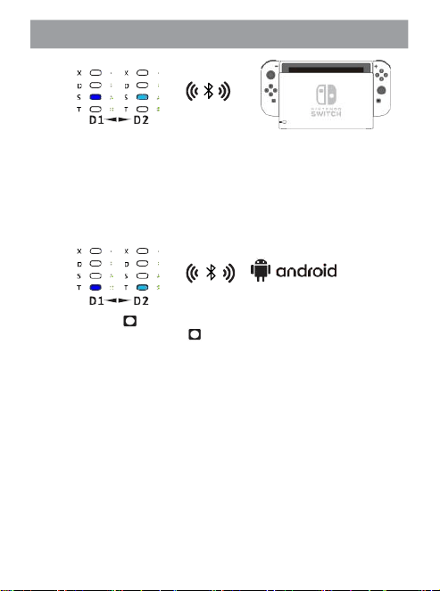
Smode:ConnectsbyBluetoothtoSwitch/SwitchLite/Switch2asProController.
●
Supports Switch wake. Press the Controller power button to turn on the Controller and wake the Switch at the
same time.
●
Supports Motion Control and vibration, but does not support HD Rumble or Amiibo peripheral sensing.
●
Supports a special setup method for Switch 2 wake. See page 18 for details.
●
Supports Controller channel number indication, shown by green indicators. See page 21 for details.
●
Supports enhanced settings, including joystick sensitivity, dead zone, button remapping, rapid fire, and macro
recording.
Tmode:ConnectsbyBluetoothtoAndroiddevicesintouchscreenmappingmode(virtualtouchmode).
●
For Android games that do not support Controllers but use fixed virtual touch controls.
●
Press the Controller [ ] button to open the floating menu and set touch properties for each button, such
as function and coordinates. Press Fn + [ ] on the Controller to display button setting prompts in a
translucent overlay.
●
Supports multiple touchscreen operation settings, including rapid taps and swipes.
●
Supports joystick range control and joystick camera mode settings, as well as Motion Control assist for
camera control.
●
Supports touchscreen macro programming. Each macro can contain up to 16 touch steps. For each touch
point, you can choose tap or slide, and independently set press duration and interval time. Flexible use
enables advanced touchscreen programming effects.
Accessory List
11
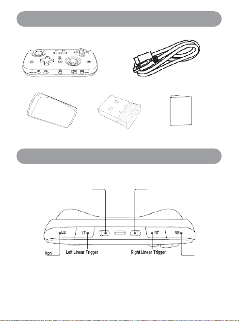
Left Trigger Mode Switch
Right Trigger Mode Switch
Right Shoulder
Button
Left Shoulder Button
Left Linear Trigger
Right Linear Trigger
Button Layout
■ Check that all included
accessories are present.
1
×
Controller
1
×
USB-A-to-USB-C data/charging cable (approx. 80 cm)
1
×
enhanced grip attachment 1
×
2.4 GHz Receiver 1
×
User Manual and Warranty Card
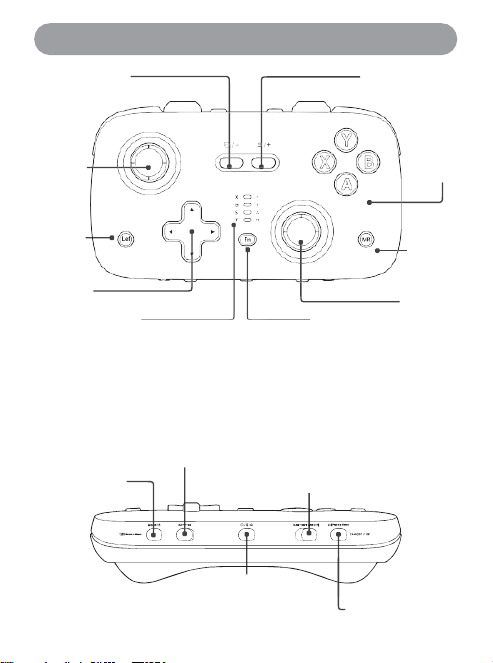
Button Layout
12
Lef
t
ex
pa
nsi
on
but
ton
ML
/
Rig
ht
ex
pa
nsi
on
but
ton
MR
VIEW/-/SELECT MENU/+/START
Left Expansion
Button / ML
Right Expansion
Button / MR
Left Joystick / L3
Right Joystick / R3
D-pad
Fn Combination Key for
TURBO and Macro
Recording
RGB Status Indicator
Green: Switch channel number indicator
Orange: USB wired connection mode
Red: Charging indicator / Battery level indicator / Macro recording &
TURBO function
Purple: 2.4 GHz wireless connection mode
Dark Blue: Bluetooth Device 1
Ice Blue: Bluetooth Device 2
Mode Switch Button
(Press and Hold) /
Battery Level Check (Fn
Key Combination)
Bluetooth
Channel
Switch
Connection Mode Switch: 2.4
GHz / Wired / Bluetooth
Power Switch / Bluetooth
Pairing Button / Home Button
Screenshot Button /
Pop-up Menu
(Bluetooth T Mode)
ABXY
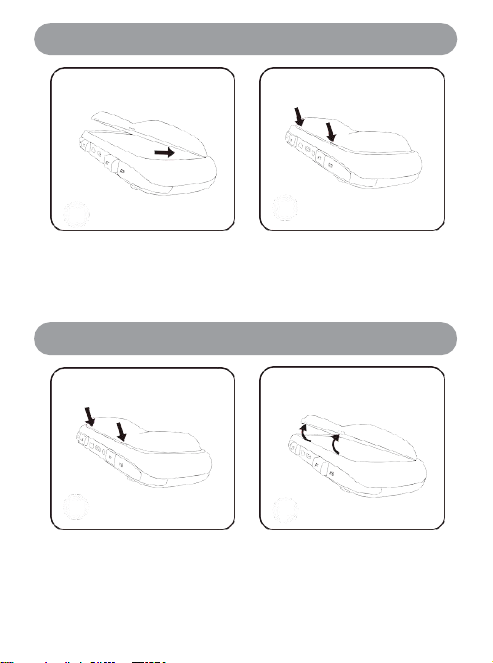
Grip Installation Instructions
13
Grip Removal Instructions
Insert the tabs at the bottom of the grip
into the gap between the rear frame and
rear cover.
Gently press down at an angle until you hear a click,
indicating that the grip is secure.
* The side of the grip edge with two notches should be on the same side as the USB-C port.
*
After the grip is installed, the Controller provides a more comfortable hold and improved
handling.
Press near the latch area at the top rear of
the Controller to disengage the grip latch
from the rear frame.
Lift the grip outward to separate it.
*
After the grip is removed, the Controller is more portable and can be stored easily in a pocket or other small
space.
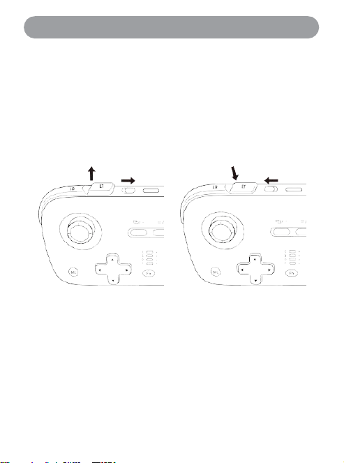
Linear Trigger / Quick Trigger Switching
14
The Controlleruses opticalLinearTriggers for preciseanalog inputwhile maintaininga compact, portable
design.
LinearTriggerfunctionON (longtravel)
Slidethe lockswitch nextto theController LT/RTLinear Triggers towardthe USB-C port. The LT/RT buttons change
to full 4 mm travel and provide high-precision linear control with 256 external levels (1280 internal levels with 5
×
precisionsampling).
* Linear functionality is not available in all connection modes or game software.
LinearTriggerfunctionOFF(short travel)
Slide thelock switch nextto theController LT/RT LinearTriggersbacktoward you.TheLT/RT buttons changeto 2
mmhalf-height travelfor fast actuation.Linearfunctionalityis disabled, makingthis settingsuitableformost games
that requirequickbuttonresponse.
4 mm travel 2 mm travel
* When switching Linear Trigger modes, the LT/RT buttons automaticallyadjust to the corresponding travel
height.
* Do not try to prevent the LT/RT buttons from entering the half-height travel position. Doing so may
damage internal components.
*
The Linear Triggers use optical potentiometers, so they are not affected by strong magnetic fields
and do not interfere with the normal operation of components such as the TMR joysticks or
gyroscope.
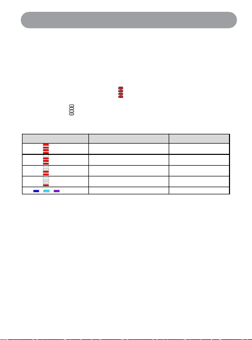
Charging / Checking Remaining Battery Power
15
The rechargeable battery installed in the Controller is not fully charged at first. Charge it before use.
Usethe USB-A-to-USB-Cdata/charging cabletoconnecttheControllertoacomputer,gameconsole,USB
charger,or power bank.
Whilecharging
Duringcharging, theindicator flashesfrom "empty"toward"full"(theredindicatorlights,andtheendof the
remaining-powerindicatorflashes).
Charging complete
Whenchargingiscomplete,all4redindicatorsstayon.
(Chargingcomplete)4indicatorsstayon
⇩USB-Cchargingcabledisconnected
(OFFstatus)Off
CheckingRemainingBatteryPower
DuringController use,press[Fn]and[MODE] to displaytheremainingbatterypower.Thebuilt-in batterylevelis
shownforabout 3 seconds inthefollowingfourstates.
Indicator LED
Indicator LED Status
Battery Level
4 red lights
Above 90%
3 red lights
About 70〜90%
2 red lights
About 40〜70%
1 red light
About 10〜40%
/ /
Mode indicator LED flashes
Below 10%
※
When the target battery level is below 10%, the current mode indicator for Bluetooth 1/Bluetooth
2/2.4GHz flashes as a warning.
●
A slow flash at the end of the red battery indicator indicates that charging has started. When charging is
complete, the red indicator stays on.
●
You can also check remaining power while charging during use by pressing the battery check button.
●
Charge at a room temperature between 10°C and 35°C (50°F to 95°F).
●
When connecting the Controller to a computer or game console using a USB data cable, if the Controller is
powered off (OFF), it connects to the computer or game console in USB wired mode.
●
If the computer/game console is in standby or sleep mode, or is switched to standby or sleep mode, charging
may not be possible or may stop.
TurningControllerPowerOn/OffandUSB/2.4GHz/BluetoothConnection
16
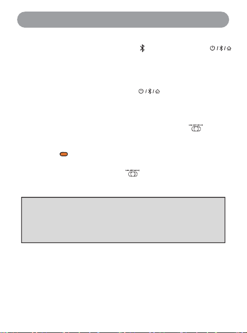
● [X]button:Xbox360Controllerwiredmode(XInputwiredprotocol)
● [A]button:Generic Controllerwired mode(DInputwiredprotocol)
●
[Y]button:ProControllerwiredmode(wiredControllerconnectionmustbeenabled inSwitchconsole settings)
● [B]button:PlayStation 3Controllerwiredmode
Power On
Set the Connection Mode switch to 2.4 GHz or Bluetooth, then press
once. The Controller powers on and connects to the paired 2.4 GHz Receiver or
reconnects via Bluetooth to a previously paired device.
Power Off
[Hardpower-off] Slidethe Connection Modeswitch to OFF.The Controller powersoff.
[Soft power-off] Press and hold the Controller button for more than 7
seconds. The Controller powers off.
* If the Controller is not operated for about 5 minutes, it automatically powers off to conserve power. To
change the auto power-off time, use the app.
USB Connection
Set the Connection Mode switchto OFF.
Connect the includedUSB-Cdatacable. After the Controller automaticallydetectsthemode requiredby the
connecteddevice, the correspondingorange indicator lights.
Automatically recognized device types: Windows PC / Android device / Nintendo Switch / Nintendo Switch 2 /
SonyPlayStation3
If automatic devicerecognitionis incorrect, or if certainsoftwarerequires a specificwired mode,youcanforce
theControllerto connect ina specifiedwired mode. Set theswitchto OFF.
Withno cableconnected, holdone of the A/B/X/Ybuttonswhileconnectingthe USB-C datacable to start the
selectedwiredmode.
* USB wired mode supports switching between XInput and DInput. Press and hold the MODE button to switch.
TurningControllerPowerOn/OffandUSB/2.4GHz/BluetoothConnection
17
Bluetooth device names for each mode: (Each mode can independently remember 2 Bluetooth®
devices.)
● [X]mode:XboxWirelessController
● [D] mode: GC-P01B D-pad/GC-P01K D-pad
● [S] mode:ProController
● [T] mode: GC-P01BD-pad/GC-P01K D-pad
2.4 GHz Connection
Make sure the Connection Mode switch is in the 2.4 GHz position. Insert the included 2.4 GHz Receiver into a PC,
Android device, Switch dock, or PlayStation 3 console, then press the Controller power button to turn on the
Controller.The purpleindicator for the correspondingmodelights.
* When using 2.4 GHz for the first time, Pairing with the Receiver is required. Press and hold the Bluetooth Pairing button
untilthe purpleindicator flashesquickly.
Bluetooth Connection
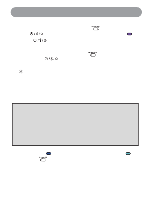
Make surethe ConnectionMode switchis in the Bluetooth position, then press the Controller power button.
Turn on the Controller.A slow-flashing blue indicatormeansBluetoothreconnection is in progress. At this time, press and
hold
the[MODE] buttonon the Controller to cyclethroughconnectionmodes.After selecting the requiredconnectionmode,press
andhold
the[ ] BluetoothPairingbutton tostartBluetoothpairingmode.Release thebutton when the blueindicatorflashesquickly,
then selecttheBluetoothbroadcast namefor thechosen mode onthe device you want to connect.
* The dark blue indicator indicates Bluetoothchannel 1,and the ice blueindicator indicates Bluetooth channel2.
* Use the slideswitch to switch device control betweenBluetoothchannels 1 and 2 at any time.
* Depending on the device Bluetooth implementation and system software, switching Bluetooth channels may cause the
software to show that the Controller currently in use has disconnected. Reconnection to the other device may occur
instantly or may take several seconds. After reconnection, some game software may require you to open settings and
reselect this Controllerbefore use resumes.
EasyPairingwiththeSwitchConsoleviaUSBCable
18
Pairing with a Switch 2 Console and Using the Wake Function
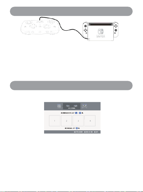
Pairing is required the first time the Controller connects to a Switch console.
Connect the included USB-C data cable to the Switch dock. The Controller automatically recognizes the connected
device and uses Pro Controller wired mode. At the same time, Bluetooth Pairing information for the Controller and
Switch console is saved automatically.After the wired connection is disconnected, the Controller can switch to Bluetooth
wireless mode and automatically connectto the Switch.
※ Switch pairing information can be saved to D1 or D2. Switch 2 wake setup is supported only on Bluetooth
channel D1.
This Controller supports a special method for copying Switch 2 Joy-Con wake information to enable the Switch 2
console wake function. Pairing is required the first time it connects to a Switch 2 console.
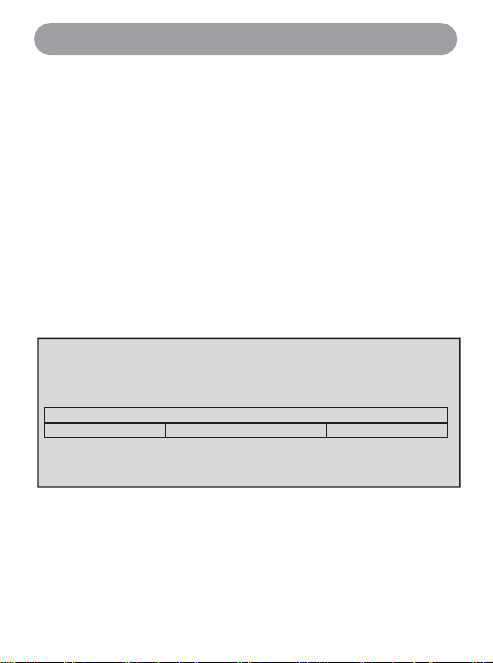
1.
Open the Switch 2 Controller search screen.
2.
Power on the Controller in Bluetooth mode on the D1 channel, then switch to S mode.Press and hold theBluetooth
Pairing button until the dark blue indicator flashes quickly to begin Pairing.
3.
After the Controller shows that connection is complete, remove the second-generation Joy-Con from the console
within 20 seconds. Wake information will be copied automatically, and you can then try waking the Switch 2
console. If wake fails, go to "Settings" - "Controllers & Accessories" - "Disconnect Controllers" on the Switch 2
console to disconnect all connected Controllers, then repeat the steps above.
* Note: Switch 2 wake setup is supported only on Bluetooth channel D1.
Basic Operations
19
TUR B O ind ica tor beh avior: After TURBO is en a ble d, the cur re n t ind ic a to r tu rn s red. W h en a butto n with rapid fire ass ig n ed is pres s ed, the re d ind ica tor sta rt s flash ing an d TU R B O
tak es effec t. Afte r TUR B O a s signme n ts a re clear ed ind iv idu a lly, or all as signme n ts a re cleared by pre s sin g Fn twice , the mo d e in dic ato r return s to the cur re n t mod e in d ic a to r colo r or
gre e n chann e l- numb e r indicatio n.
Connection Mode Selection
USB wired: Connects to gaming devices over a wired connection at a 1 kHz polling rate, with automatic or manual
selection of a supported device mode. Suitable for high-interference environments, precision racing games, and emulator
testing.
2.4 GHz wireless:
Connects to gaming devices wirelessly at a 1 kHz polling rate and automatically selects a
supported device mode. Suitable for most games and competitive scenarios, with special support for controller switching
when two Controllers are connected.
Bluetoothwireless: Connects to gaming devices wirelessly at a 200 Hz polling rate and provides the broadest
compatibility. During power-on reconnection or while connected, press and hold the [MODE] button to switch modes.
[X]mode:ConnectstoPC/iPad/iPhone/Androiddevices(smartTVs) inXInputmode.
[D]mode:ConnectstoPC/Androiddevices(smart TVs)/RaspberryPiinDInputmode.
[S]mode:Connects to Switchconsoles/ connectstothePC SteamplatforminPro Controllermode.
[T]mode:Connects toAndroid devicesin virtualtouchmode(activetouchscreenmapping technology).
※ For details on the features and compatible devices of each mode, see Compatibility on page 4.
TURBOSettings(RapidFire/ AutoRapid Fire)
Rapid fire: Press Fn + a function button to start.
Auto rapid fire: Press Fn + the same function button twice to start.
Rapid-fire speed:
Press Fn + right joystickup/down to adjust the global rapid-fire speed.
Three levels are
available: slow, medium, andfast. To clear all TURBO assignments, press Fn twice.
※ In the app, rapid-fire status can be adjusted separately for each button. Buttons that can be set for rapid fire:
A/B/X/Y/LB/RB/LT/RT/LS/RS/➖/➕.
The flashing frequency of the four red indicators corresponds to the rapid-fire speed.
Slow flash: 5 times/second
Medium speed: 12 times/second
Fast flash: 33 times/second

Basic Operations
20
RecordingMacros with theML/MR ExpansionButtons
Recording: Press Fn + ML/MR to start macro recording. The indicator for the current mode turns red, indicating that
macro recording can begin.
Saving a macro: After entering the button sequence, press ML/MR again to save it. The red indicator turns off. Clearing a
macro: Hold Fn and press ML/MR twice to clear it. (This saves an empty macro.)
※ Macro recording supports recording up to 42 button-sequence entries, including joystick and button timing.
● By default, ML/MR are not assigned to any button at the factory. To use macro button functions, assign them first.
● To prevent accidental input, clear the saved button sequence when macro buttons are not needed.
● Macro button memory is shared across all function modes.
● For later macro editing, use the waterfall chart on the Macrotab in the mobile app to fine-tune parameters precisely.
● This Controller supports cloud macros. Use the mobile app to downloadmove sets for different games and
characters.
● While settings are being configured in the mobile app, the Controller can continue to operate normally.
● When the left/right joystick is pressed, it may be shown as L3/R3 or LS/RS, depending on the platform.
MappingButtonswith the ML/MRExpansionButtons
When only one buttonis recordedto an expansion button, the expansionbutton functions as a mappedbutton.
※ To change mapping for the Controller body function buttons, use the mapping menu page in the app.
Using the ML/MR ExpansionButtonsforForced MotionControl (Replacing theRight Joystick)
When only the [ ] button is recordedto an expansion button, thatexpansion button becomesthe MotionControl activation
button (the gyroscope replaces the right joystick).
● If one [ ] button is recorded, hold the expansion button to enable Motion Control; release it to disable the function.
● If two [ ] buttons are recorded, press the expansion button once to enable Motion Control, then press it again to
disable Motion Control.
※ In Switch mode, the [ ] button is mapped as the screenshot/video capturebutton and does not function as a
Motion Control switch. When 2 or more buttons other than this button are recorded, they are saved as a button
sequence (macro setting).
Basic Operations
21
Switching Control BetweenTwoControllers
Requirementsfor switching betweenControllers:
Use 2.4GHz modewithtwo Controllersconnectedto one 2.4GHzReceiver.
Preparation beforeuse:
1.
Insert the2.4GHzReceiverintothegameconsole(PC/Androiddevice/Switch/PlayStation3).
2.
Set thefirstControllerslideswitchto the2.4 GHzpositionandturnit on. IfPairing isrequired, pressandhold the
Bluetooth Pairingbuttonto pair. Connect thesecondControllerin thesameway.
※ Do not use the Receiver for another Controller of the same model during Pairing with the Receiver.
3.
During a game,press Fn + [ ] to switchcontrolbetween thetwo Controllers.
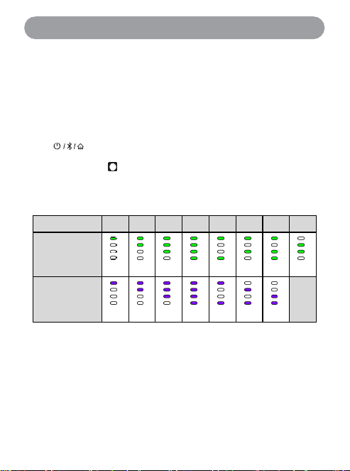
Switch/PlayStation 3 Connection Channel NumberIndicator
AftertheControlleris connectedto a Switch/PS3console,a channelnumberis assignedautomaticallyaccording tothe device
connectionorder,andthemodeindicatorchangesto the correspondingcolor channel-numberindicator.
Controllerchannelindicator numbers are shown inthe tablebelow:
No.
1
2
3
4
5
6
7
8
Switch
PS3
● The initial Controller number varies depending on the connected-device status of the Switch/PS3.
● The Controller channel indicator display matches the assignment shown in the Switch/PS3 control interface.
● The PS3 channel number color matches the operating mode: purple for 2.4 GHz and orange for USB wired.
● Under standard conditions, the Switch dock and PS3 console can connect 2 wired Controllers or 4 2.4 GHz
Controllers at the same time. More Controllers require a compatible USB hub.

Basic Operations
22
● Install the "KeyLinker" smartphone/tablet app.
Thebuttonconfigurationcenterinthisappcanmodifymorethantenfunctionalparameters,includingControllerbutton
mapping,Vibrationintensity,joysticksensitivity,andTriggertravel.Youcanalsosetlightingcolorsandtransition
methods,adjustrecordedmacroparameters,andmore.TheController canremainconnectedtoboththegaming
deviceandtheappduringconfiguration.
Operating System
Android
®
app:Android 5.0 or lateriOS
®
app: iOS10.0or later
SoftwareDownloadand Installation
Android®
IntheGooglePlaystore,searchfor"KeyLinker,"locatetheappicon,then downloadandinstallit.
* Inmainland China,searchfor"KeyLinker"inappstoressuch as TencentMyApp,360AppStore,OPPO,vivo,
ZTE,andHuaweitodownloadit.
iOS®
IntheAppStore,searchfor"KeyLinker"andlocatetheapp.
Downloadandinstallit.
ButtonConfigurationCenterConnection:
Ona smartphone ortablet,
1.
launch "KeyLinker."
2.
From the Bluetoothdevicelist, selectthe displayed devicename "GC-P01B Settings-XXXXXX"or "GC-
P01K Settings-XXXXXX" toconnectthe Controller settings interfacetothe smartphoneby Bluetooth.
3.
Afterconnection iscomplete,tap thegearicon to open the Controllerconfiguration center.
Resetting the Controller (RESET)
23
About Firmware Update
Note: During the update process, do not force quit "KeyLinker" or turn off Bluetooth or power off the phone/tablet.
Otherwise, the OTA update may fail. Even if the firmware update does not complete successfully, the Controller stores
backup firmware and can automatically restore the previous version to maintain normal operation.
Gyroscope (Motion Control) Calibration
Ifthe Controllerbecomes unresponsiveduring operation,press andhold the Controller power button.
After about 7 seconds, the Controller powers off. You can also slide the operating status switch directly to
OFF. A normal forced shutdown does not delete Controller settings, such as device connections, macro
programming, or Vibration level. To restore factory settings, use "Restore Factory" in the app function menu.
Method 1:The USB-Cport on this Controller supports USB firmware updates.Launch the latest firmwareupdater on the
computer.With the Connection Mode switch in the OFF position,press and hold the leftjoystick L3 button, then connect
the USB cable.When theupdate button becomes available,click Firmware Update.
Method 2:When the Controller is connectedto a phone by Bluetooth,update it throughthe "FirmwareUpdate" menu inthe
dedicatedKeyLinker app.
If Motion Control behaves abnormally during Controller use, try recalibrating the built-in gyroscope. To start
calibration: With the Controller powered off, set the operating status switch to 2.4 GHz or Bluetooth. Press and hold
[A + ] at the same time, then turn on the Controller. Mode indicators 1/2 and 3/4 flash alternately in red,
indicating gyroscope calibration mode. Place the Controller on a level surface, such as a table, and press the
[ ] button to start calibration. After about 1 second, calibration completes automatically, the Controller exits
calibration mode, and then powers off.
※ Each Controller is horizontally calibrated before leaving the factory. This operation is not required unless drift
occurs.
Copyright and Trademarks
24
The Bluetooth
®
word mark and logos are registered trademarks owned by
Bluetooth SIG, Inc. Other trademarks and trade names are the property of their
respective owners.
Nintendo Switch/Switch 2 is a registered trademark or trademark of Nintendo Co.,
Ltd.
PlayStation, PS3, PS4, and PS5 are registered trademarks of Sony Interactive
Entertainment (SIE).
Windows, Xbox, Xbox 360, Xbox One, and Xbox Series S/X are registered
trademarks or trademarks of Microsoft Corporation in the United States and/or other
countries or regions.
Android is a registered trademark or trademark of Google Inc.
Mac, macOS, and iOS are registered trademarks or trademarks of Apple Inc. in the
United States and/or other countries or regions.
The Steam gaming platform and its graphic logo are registered trademarks of Valve
Corporation.
QR Code is a registered trademark of DENSO WAVE INCORPORATED.
USB Type-C
®
and USB-C
®
are registered trademarks of USB Implementers
Forum.
Other system names and product names appearing in this document are generally
registered trademarks or trademarks of their respective developers.
Please note that ™ and ® symbols are not shown throughout this document.
Specifications Overview
25
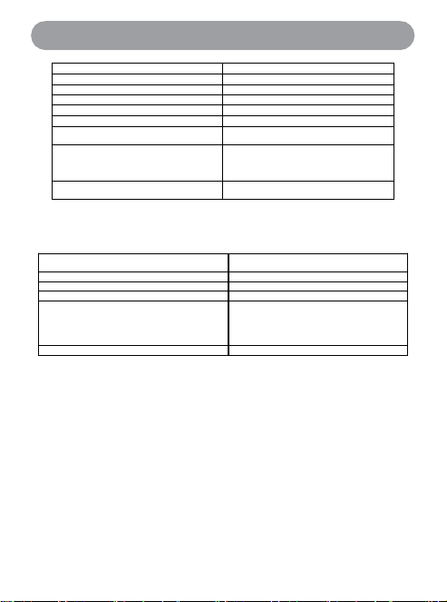
Power supply (USB-C input)
DC 5 V, 480 mA
Built-in battery
Lithium battery 3.7 V (1000 mAh)
Operating time*1
Approx. 10 hours
Charging time*2 (25
°
C)
Approx. 3 hours
Charging temperature range
10
°
C to 35
°
C (50
°
F to 95
°
F)
Operating temperature range
0
°
C to 40
°
C (32
°
F to 104
°
F)
Operating humidity range
35% RH to 80% RH (non-
condensing)
External dimensions (width × depth
×
height)
133 x 75 x 24 mm (trigger
retracted)
133 x 77 x 24 mm (trigger
extended)
Weight
Approx. 104 g (without grip)
Approx. 113 g (with grip)
*1 Shorter depending on game conditions, such as Vibration intensity and frequency, and Controller settings.
*2 Time required to charge from empty to full.
Bluetooth® Section
Bluetooth® system specifications
BLE5.0
Wireless device classification
Class 2
Bluetooth® power consumption
15 mW (typ.)/60 mW (max.)
Frequency band
2402 MHz to 2480 MHz
Supported modes
XInput: Xbox One controller PC mode
DInput: Universal game controller;
Switch: Pro Controller
Touchscreen Mapping: Android
touchscreen mapping
Operating distance
Up to 10 meters (33 feet)
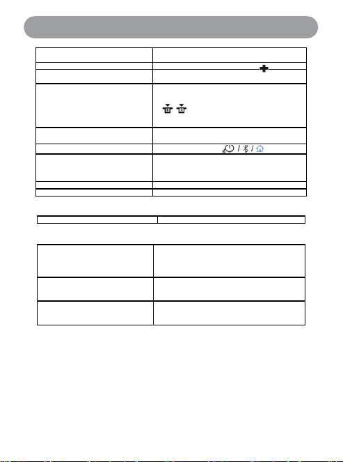
Specifications - Controls
Analog joystick
2 TMR (Tunnel
Magnetoresistance)/Contactless
D-pad
Conductive rubber 8-way D-pad:
Quick trigger
2 optical potentiometers, 4 mm/2 mm button
travel, 1280 steps
Game function buttons
12: A/B/X/Y
LB RB LT RT
VIEW[ ] MENU[ ]L3/R3[]
(L3/R3 are when the left and right joysticks
are pressed, LT/RT are linear triggers)
Macro programming buttons
2: ML/MR
Product function buttons
4: MODE/Fn//Screenshot
Slide switches
2: Two-position channel switch: Bluetooth
device 1/2 selection
Three-position status switch: 2.4
GHz/wired/Bluetooth
Vibration motor
Two symmetrical button-type rotor motors
Motion control
Six-axis motion sensing
Terminal Section
Controller USB-C input
DC 5 V, 480 mA
Accessories Section
Removable enhanced grip
attachment
ABS+PC, about 9 grams
USB receiver
USB-A nano receiver, dual-Controller 2.4
GHz connection
USB-A-to-USB-C charging
cable
Approx. 80 cm (2.6 ft)
SkyLarkS1ProPortableController
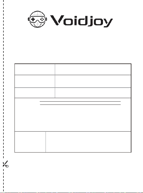
Warranty service (free repair) for Voidjoy peripheral products begins on the date of purchase.
During the warranty period, products may be serviced only at repair shops authorized by
Voidjoy. When requesting warranty service, present this Warranty Card and proof of purchase,
such as the invoice.
(Warrantyterms and productregistrationidentification codeare shownon the back.)
Model
GC-P01B/GC-P01K
Warranty Period
One year for the main unit from the date
of purchase
* Excludes the enhanced grip attachment and charging cable
accessories.
Purchase Date
Year Month Day
Customer Name
ContactAddress
Phone
R e t a i l
S t o r e
Dealer Name/Address
Phone
Voidjoy official website: https://www.voidjoy.cn Voidjoy Interactive
(Shenzhen) Co., Ltd.
Serial number and QR code label area
Warranty Terms
1.
Thankyouforpurchasinga VoidjoyInteractiveproduct.To receive fullafter-salesservice
support, firstscan theQRcodewithWeChattocomplete onlineauthenticity verification and
product registration.
2.
Whenrequestingwarrantyservice,present thiswarrantycertificateandthepurchaseinvoice.Pleasenotethe
following:
a.
Do not remove, smear, or soil the serial number barcode and QR code service label attached to this
warranty certificate.
b.
This warranty certificate will not be reissued if lost. Keep it in a safe place.
c.
This warranty certificate is valid only in mainland China and is not currently valid in Hong Kong, Macao, or Taiwan.
3.
Warrantyserviceis providedforfailuresthatoccurduringnormalusewithin1 yearfrom thedateof purchase.
4.
Evenwithinthewarrantyperiod,thefollowingcasesarenotcovered bywarranty;however,paid repairmaybe
available:
a.
Damage caused by use, maintenance, or storage that does not follow the product instruction manual.
b.
Damage caused by incorrect operation, abnormal power supply, impact, dropping, or similar causes.
c.
Damage caused by disassembly or repair by personnel other than a repair shop authorized by Voidjoy.
d.
Failure to present this warranty certificate and a valid purchase invoice.
e.
The information recorded on the warranty certificate does not match the product identification or has been
altered.
f.
Damage caused by force majeure, such as lightning, earthquake, fire, or flood.
5.
This warrantytermappliesonlywhentheproductispurchasedandusedbyanindividualconsumerforpersonal
use.Itdoesnotapplytobusinessorothercommercialuse.
6.
Faultdescriptionforservice inspection:
□ Cannot power on or start □ Optical Trigger potentiometer damaged (no function or no spring return)
□ Vibration motor abnormal
□ Joystick drift or failure □ Controller housing defect or damage
□ Motion Control abnormal or failed □ Bluetooth wireless connection failure
□ Charging port damaged □ Firmware update failed □ Battery damaged or worn
□ Indicator failure. Check the affected mode indicator: X[ ] / D[ ] / S[ ] / T[ ]
□ Button failure. Mark the button name.
Other fault. Please describe.
Removing the Battery When Disposing of This Product
Rechargeable lithium-ion batteries contain valuable materials. When disposing of this product, remove the
battery installed in the unit and recycle it. After removal, insulate the terminals with clear tape or similar
material, thentakeit to a localrecycling facility.
Do not dispose of lithium-ion batteries with regular household waste. Discarded lithium-ion batteries
may be damaged by waste collection vehicles and cause a short circuit, resulting in fire or smoke.
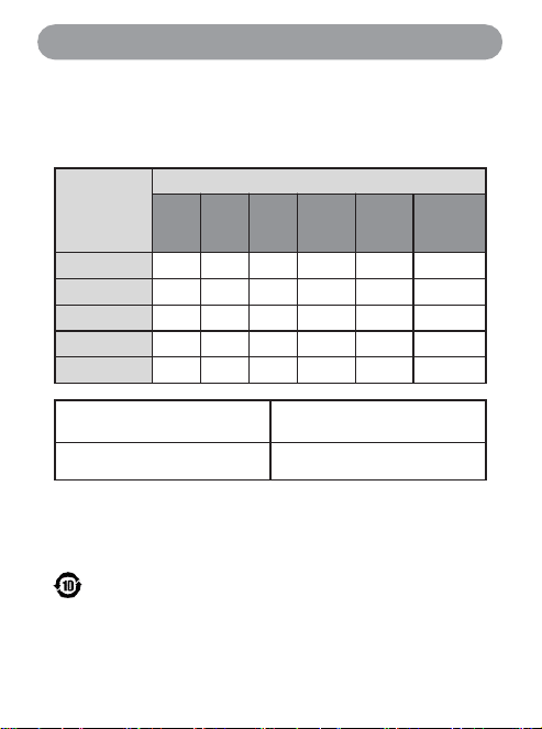
Names and Contents of Hazardous Substances in the Product
Part Name
Hazardous Substances
Lead (Pb)
Mercury
(Hg)
Cadmium
(Cd)
Hexavalent
Chro m ium
(Cr (VI))
Polybrominated
Biphenyls (PBB)
Polybrominated
Diphenyl Ethers
(PBDE)
Housing, Structure
○
○
○
○
○
○
PCB Board
×
○
○
○
○
○
Lithium-ion Battery
○
○
○
○
○
○
USB Charging Cable
○
○
○
○
○
○
Terminal Contacts
○
○
○
○
○
○
Operating temperature range: 0
°
C to
40
°
C
Storage temperature range:
-10
°
C to 50
°
C
Operating humidity range: 35% to
80%
Storage humidity range: 35% to 80%
This table is prepared in accordance with SJ/T 11364.
○: Indicates that the content of this hazardous substance in all homogeneous materials of this part is below the limit
specified in GB/T 26572.
×: Indicates that the content of this hazardous substance in at least one homogeneous material of this part
exceeds the limit specified in GB/T 26572.
Items marked "
×
" are exempt under the EU RoHS Directive.
Thiselectricalandelectronic product containscertainhazardoussubstances.It canbeusedsafelyduringthe
environmentalprotectionuseperiod.Aftertheenvironmental protectionuseperiodexpires,itshould entertherecycling
system.

Producer: Voidjoy Interactive (Shenzhen) Co., Ltd.
Address: A4-1207, Building A, Kexing Science Park, No. 15 Keyuan Road, Nanshan
District, Shenzhen
Manufacturer: Red Technology (Dongguan) Co., Ltd.
Address: Room 101, Building 8, No. 780 Xiecao Road, Xiegang Town, Dongguan City,
Guangdong Province, China
Website: https://www.voidjoy.cn
Scan for Online
After-Sales Service
Country of Origin: China
Issued: June 2026

FCC Statement
This equipment has been tested and found to comply with the limits for a Class B digital device, pursuant to
Part 15 of the FCC Rules. These limits are designed to provide reasonable protection against harmful
interference in a residential installation. This equipment generates uses and can radiate radio frequency
energy and, if not installed and used in accordance with the instructions, may cause harmful interference to
radio communications. However, there is no guarantee that interference will not occur in a particular
installation. If this equipment does cause harmful interference to radio or television reception, which can be
determined by turning the equipment off and on, the user is encouraged to try to correct the interference by
one or more of the following measures:
-- Reorient or relocate the receiving antenna.
-- Increase the separation between the equipment and receiver.
-- Connect the equipment into an outlet on a circuit different from that to which the receiver is connected.
-- Consult the dealer or an experienced radio/TV technician for help.
This device complies with part 15 of the FCC Rules. Operation is subject to the following two conditions: (1)
This device may not cause harmful interference, and (2) this device must accept any interference received,
including interference that may cause undesired operation.
Changes or modifications not expressly approved by the party responsible for compliance could void the
user's authority to operate the equipment.
FCC&ISED Radiation Exposure statement
The device has been evaluatec to meel general RF exposure requirement. The device can be used
in portable exposure condition without restriction.
Déclaration d’exposition aux rayonnements FCC&ISED
Le dispositif a été évalué en fonction des exigences générales d’exposition aux RF. L’appareil
peut être utilisé en condition d’exposition portable sans restriction.
- The device contains licence-exempt transmitter(s)/receiver(s) that comply with Innovation,
Science and Economic Development Canada’s licence-exempt RSS(s). Operation is subject to the
following two conditions:
- (1) This device may not cause interference.
- (2) This device must accept any interference, including interference that may cause undesired
operation of the device.
- L’émetteur/récepteur exempt de licence contenu dans le présent appareil est conforme aux
CNR d’Innovation, Sciences et Développement économique Canada applicables aux appareils
radio exempts de licence. L’exploitation est autorisée aux deux conditions suivantes :
- 1. L’appareil ne doit pas produire de brouillage;
- 2. L’appareil doit accepter tout brouillage radioélectrique subi, même si le brouillage est
susceptible d’en compromettre le fonctionnement.