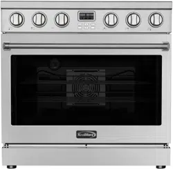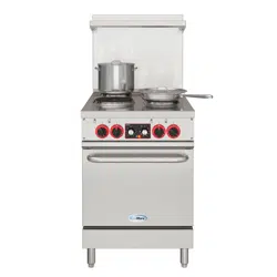
ELECTRIC RANGE
36 Inch Professional All-Electric
Range Stainless Steel with Legs, 4.3
Cu. Ft.
USER MANUAL
Before using, please read the operating instructions carefully to
ensure proper application and achieve satisfactory results.
For any service related issues, please contact us:
718-576-6342
suppor[email protected]
Models: KM-FR36EE-SS
Stay informed with the latest information for your
KoolMore Appliance.
Scan the QR code below to access the most recent user manual
on our website, which is constantly being updated and improved.
If you need any assistance or have questions, our customer support
team is here to help.
Phone- 718-576-6342 Email- suppor[email protected]
Please write down the model number and serial number below for future reference. Both numbers are located on the
rating label on the back of your unit or inside of the unit and are needed to obtain warranty service. You may also
want to staple your receipt to this manual as it is your proof of purchase and may also be needed for service
under warranty.
Model Number:
Serial Number:
Date of Purchase:
To better serve you, please do the following before contacting customer service:
If you received a damaged product, immediately contact the retailer or dealer that sold you the product.
Read and follow this User Manual carefully to help you install, use, and maintain your unit.
Refer to the Troubleshooting section of this manual as it will help you diagnose and solve many common issues.

3
Contents
Safety .............................................................................................. 4
Parts .............................................................................................. 6
Installation Preparation .................................................................. 7
Tools & Parts ................................................................................... 9
Installation ...................................................................................... 10
Electrical Hook-Up .......................................................................... 13
Operation ........................................................................................ 15
Maintenance ................................................................................... 21
Troubleshooting .............................................................................. 23
Warranty .......................................................................................... 24

4
Safety
This manual and your appliance include important safety messages. Always read and follow all
safety instructions carefully.
Safety Alert Symbol
This symbol warns you about potential hazards that could cause serious injury or death.
Every safety message will follow the safety alert symbol and include the words “DANGER” or
“WARNING.”
• DANGER — You can be killed or seriously injured if you don’t immediately follow these instruc-
tions.
• WARNING — You can be killed or seriously injured if you don’t follow these instructions.
Each message tells you what the hazard is, how to reduce the risk of injury, and what could happen
if the instructions aren’t followed.
General Safety
• Remove all packaging materials before using this appliance. Never allow children to play with
packaging. Do not remove the model or serial number plate attached to the unit.
• Ensure your appliance is installed and grounded by a qualied technician in accordance with
the National Electrical Code (ANSI/NFPA 70) and all applicable local codes. In Canada, installa-
tion must comply with CSA Standard C22.1 (Canadian Electrical Code, Part 1) and local codes.
• Install the appliance only according to the instructions in this manual.
WARNING: Risk of Fire or Explosion
If these instructions are not followed exactly, a re or explosion could cause property damage,
injury, or death.
For Your Safety:
• Do not store or use gasoline or other ammable vapors and liquids near this or any other appli-
ance.
• A qualied technician must perform installation and service. Keep the appliance’s power
source accessible and know how to disconnect it in case of an emergency.
• Do not repair or replace any part of this appliance unless instructed to do so in this manual. A
qualied technician should do all other servicing.
• Do not modify, alter, or remove panels, wire covers, or other parts of the appliance.
Prevention of Burns and Fire
• Do not use or store ammable materials such as paper, plastic, towels, or cleaning rags on or
near the appliance.
• Keep the area around the range clear of gasoline and other ammable vapors or liquids.
• Do not store anything inside the oven.
• Do not let children climb, sit, or play on the appliance. Items of interest should not be stored in
cabinets above the range or on its backguard.

5
• Do not touch heating elements or nearby areas while the appliance is in use or cooling down.
These surfaces can remain hot even when not visibly glowing.
• Avoid wearing loose clothing while cooking. Keep ammable materials away from hot surfac-
es.
• Always use dry potholders—moist potholders can cause steam burns. Never use towels or
bulky cloths in place of potholders.
• Never heat unopened containers; pressure buildup could cause them to burst.
• Never use this appliance to heat or warm a room — doing so may cause overheating and dam-
age.
• Watch heating fat or grease closely. If grease ignites, smother ames with a lid, or use baking
soda or a Class B or ABC re extinguisher.
Use a re extinguisher only if:
• You know how to use it.
• The re is small and contained.
• You have called the re department.
• You have a clear escape route.
Surface Use and Maintenance
• Always check which knob controls which heating element. Make sure the heating element is lit
before adjusting the heat setting.
• Clean the appliance regularly to prevent grease buildup, which can cause res. Keep the hood
and lters clean.
• Turn utensil handles inward to prevent accidental spills or burns.
• Do not leave heating elements unattended, especially when set to high heat. Boilovers can
cause smoke and may ignite.
• Do not use aluminum foil to line oven parts. Use foil only to cover food during cooking.
• Use only cookware suitable for high heat, and check manufacturer recommendations.
• Do not use decorative burner covers—they can overheat, melt, and cause burns or damage.
• Use pans that are properly sized with at bottoms, ensuring they fully cover the heating ele-
ment for optimal eciency and safety.
Tip-Over Safety
WARNING: Tip-Over Hazard
To reduce the risk of the range tipping over:
• The range must be secured by a properly installed anti-tip bracket.
• To verify proper installation, carefully slide the range forward and check that the rear foot is
securely under the bracket before sliding it back.
The range will not tip during normal use, but excessive force on the open door can cause it to tip,
resulting in serious injury or death.
Instructions:
• Connect the anti-tip bracket to the rear range foot.
• Reconnect the bracket if the range is moved.
• See the installation section for details.
• Failure to follow these instructions can result in death or severe burns, especially to children or
adults.
6
Parts

7
Proper installation and ventilation are essential to ensure safe and ecient operation of your
range. Please read these guidelines carefully before installation. Always check your local building
codes, as requirements may vary from those described in this document.
It is recommended that a range hood rated for at least 400 CFM be installed above the appliance
to provide adequate ventilation. Follow the hood manufacturer’s instructions for proper mounting
distance.
General Installation Guidelines
• Observe all applicable codes and ordinances. Do not block or obstruct airow for ventilation.
• The installer is responsible for complying with the clearances specied on the model/serial
rating label.
• Install the range in a location convenient for kitchen use.
• Recessed installations must provide a complete enclosure of the sides and rear of the range.
• To prevent burns or re from reaching over-heated surfaces, avoid placing cabinets directly
above the cooking surface. If storage above is unavoidable, install a range hood or microwave
hood combination rated for at least 400 CFM that projects horizontally a minimum of 5” (12.7
cm) beyond the cabinet bottom. (See Figure 1)
• Maintain at least 30” (76.2 cm) of clearance between the cooking surface and the bottom of
the range hood. The hood must be vented directly to the outside or through ues. (See Figure
1)
• Avoid placing cabinetry directly above the range when possible. If used, cabinets above the
cooking surface should be no more than 13” (33 cm) deep. Ensure surrounding walls, counter-
tops, and cabinets can withstand temperatures up to 200°F (93°C). (See Figure 1)
• Cabinet opening dimensions shown in this manual are minimum clearances and must be fol-
lowed. (See Figure 1)
• Maintain at least 18” (45.7 cm) of clearance between countertops and the bottom of cabinets
adjacent to the range.
• Seal all openings in the wall or oor where the range is installed.
• Have a qualied ooring professional verify that your oor covering can withstand tempera-
tures of at least 200°F (93°C).
• If installing over carpet, place an insulated pad or ¼” (0.64 cm) plywood under the range.
• Install the supplied anti-tip bracket securely to the oor. Refer to the “Install Anti-Tip Bracket”
section for instructions.
• A grounded electrical supply is required. See the “Electrical Requirements” section.
Mobile Home Installation
If the range will be installed in a manufactured or mobile home, the installation must conform
to Title 24 CFR, Part 3280 (formerly HUD Standard Part 280), or, when not applicable, to ANSI
A225.1/NFPA 501A or local codes.
In Canada, installation must comply with CAN/CSA-A240 (latest edition) or local codes.
Installation Preparation

8
When installing the range in a mobile home, it must be secured to the oor for transit. Any method
of securing the range is acceptable as long as it meets the applicable standards above.
Warning
To prevent cabinet damage, verify with your builder or cabinet supplier that the materials surround-
ing the range can withstand heat. This oven complies with UL and CSA International standards
and meets the maximum allowable wood cabinet temperature of 194°F (90°C).
Electrical Requirements
Warning – Electrical Shock Hazard
Do not use an extension cord. Failure to follow these instructions can result in death, re, or elec-
trical shock.
• A qualied service technician must perform any additions, changes, or conversions required to
meet installation needs in accordance with the manufacturer’s instructions and all local codes.
• This appliance is not supplied with a plug. If installed with a plug, it must be done by a qualied
technician using a 4-prong, 3-phase plug designed specically for freestanding ranges.
• This appliance may also be connected directly to the main electrical supply (without a plug) as
described in the “Electrical Connection” section.
• Do not operate this appliance using a 2-prong adapter or extension cord. If only a 2-prong out-
let is available, it must be replaced with a properly grounded 4-prong, 240V outlet installed by a
licensed electrician.
• Severe shock or appliance damage may occur if not installed by a qualied technician or elec-
trician.
• Power Supply: 220–240V / 50–60Hz
• Recommended Circuit: 50 Amp dedicated circuit protected by a time-delay fuse or breaker
• Total Input Power: 11.7 kW (48.75 A)
• For personal safety, the appliance must be properly grounded.
• See the “Installation Instructions” included with the appliance for complete electrical and
grounding details.

9
Gather the required tools and parts before starting installation.
Read and follow the instructions provided with any tools listed here.
• Tape measure
• Phillips screwdriver
• Flat blade screwdriver
• 1/8” at blade screwdriver
• Level
• Hand or electric drill
• Wrench or pliers
• 1/8” (3.2 mm) drill bit (for wood oors)
• Marker or pencil
• 3/16” (4.8 mm) carbide-tipped masonry drill bit (for concrete/ceramic oors)
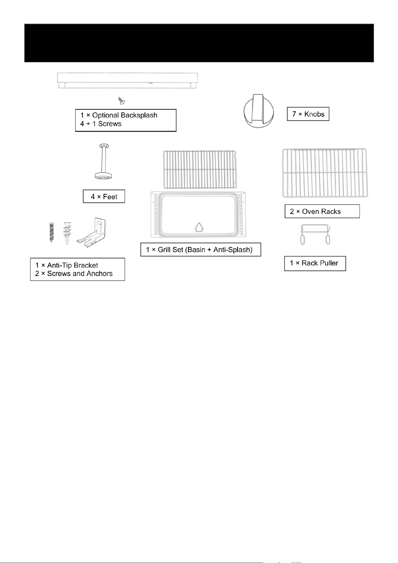
Parts Supplied:
Check that all parts are included.
• 3 - Oven racks
• 1 Anti-tip brackets
• 2 plastic anchors
• 2 screws
The anti-tip bracket must be securely mounted to the oor. Thickness of ooring may require lon-
ger screws to anchor bracket to suboor.
Tools & Parts
10
Installation
11
Unpacking and Installing the Range
Use two or more people to move and install the range.
Failure to follow these instructions can result in death or serious burns.
Unpacking the Range
• Remove all shipping materials from the range. Do not remove the protective lm or tape secur-
ing the drawer.
• Remove the oven racks and accessories from inside the oven.
• Carefully lay the range on its back. Use the four (4) L-shaped cardboard corners from the car-
ton to protect the oor and the appliance. Stack two corners together for extra support and
place them lengthwise behind the range.
• With two or more people, gently lower the range onto the cardboard supports.
• Install the leveling feet one at a time. The feet are located inside one of the oven boxes.
• Place a piece of cardboard or hardboard in front of the range. With two or more people, stand
the range upright on the board.
• Remove the protective lm and tape from the appliance and drawer.
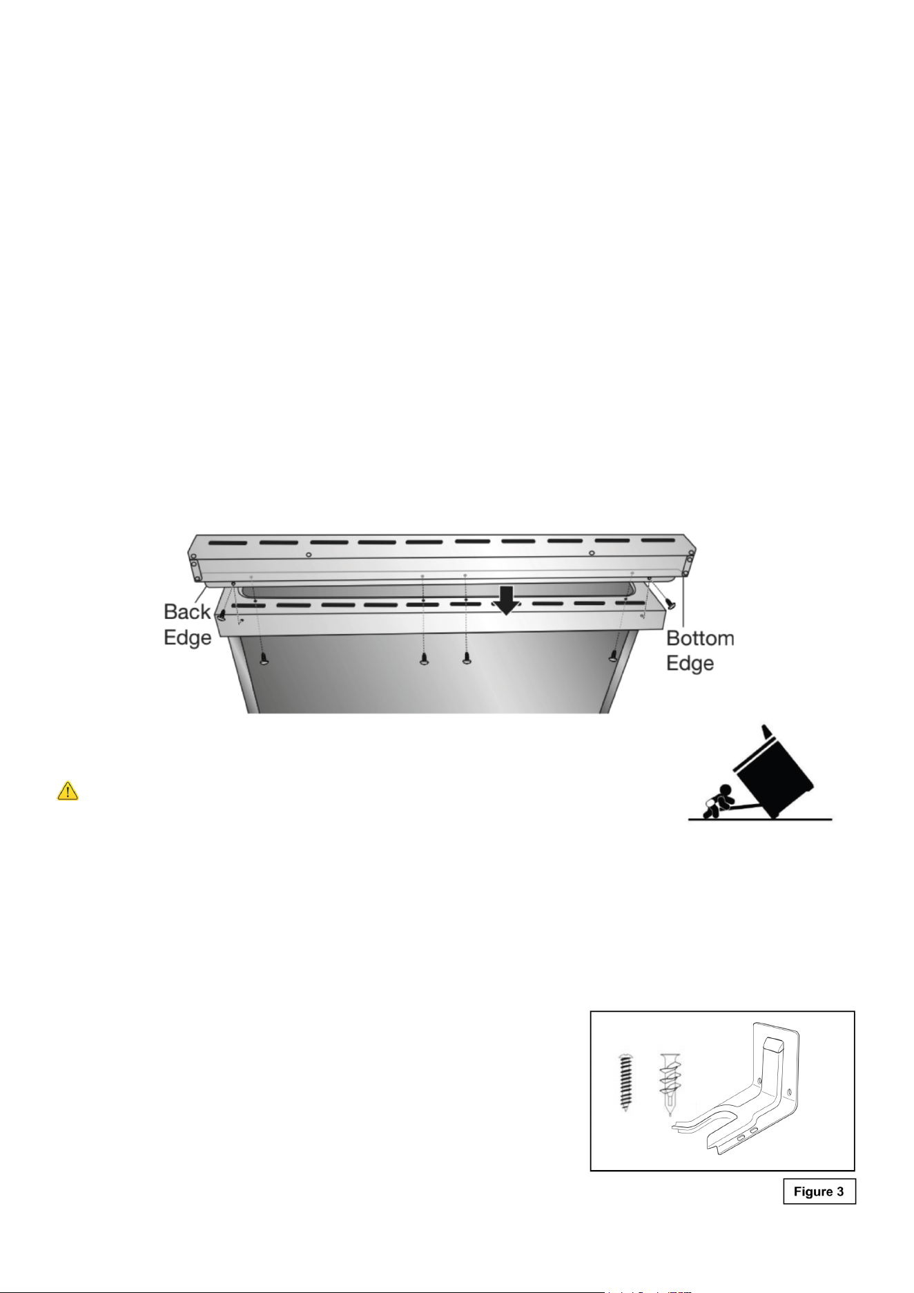
• Install the stainless-steel backsplash:
• Align the holes in the backsplash with the holes on the rear stovetop edge.
• From underneath, insert and tighten the bottom screws.
• Insert and tighten the two side screws through the back edge of the backsplash into the
cooktop.
Installing the Anti-Tip Bracket
Tip-Over Hazard
A child or adult can tip the range and be killed.
• Secure the range using the supplied anti-tip bracket.
• Reconnect the bracket if the range is moved.
Failure to follow these instructions can result in death or serious burns.
Tools Required
• Drill (hand or electric)
• 3/16” (4.6 mm) masonry drill bit for concrete/ceramic oors
• 1/8” (3.2 mm) drill bit for wood oors
• Flat-blade screwdriver
• Hammer
• Measuring tape
• Masking tape
• 2 screws and 2 plastic anchors (provided)
• Anti-tip bracket (provided)
12
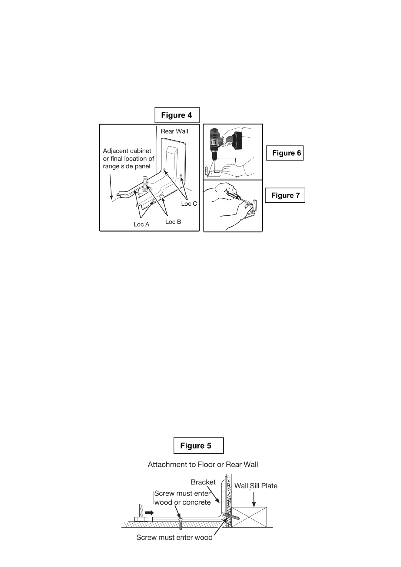
4. Mark and Drill Holes – Mark the holes to be drilled.
• For oor installation, use Loc A or B.
• For rear wall installation, use Loc C.
5. Secure the Bracket:
• Wood Floor: Use the provided screws to secure the bracket through the marked holes (Loc A
or B).
• Concrete Floor: Drill 5/32” pilot holes, 2” deep, and insert anchors. Secure with the provided
screws.
• Rear Wall: Use the two screws provided at Loc C. Screws must enter a solid wood sill plate.
If the wall contains metal studs, secure to the oor instead.
6. Verify Installation:
• Slide the range into position. Ensure the rear leveling leg is fully engaged in the anti-tip bracket
(see Figure 5).
• To conrm proper installation, look under the range to verify engagement. If visual inspection
is dicult, slide the range slightly forward and check that the bracket is rmly attached and the
rear foot is under it.
If the range is moved for cleaning or servicing, always repeat this check before using the appliance
again.
Installation Steps
1. Determine Final Location – Decide where the range will be positioned before installing the
bracket.
2. Position the Bracket – Place the bracket on the oor so the back edge aligns with the rear wall
or the back of the range in its nal position (see Figure 4).
• If the bracket does not reach the wall, it must be fastened to the oor.
3. Align the Bracket – Position the bracket against the adjacent cabinet or align it with the side
of the range. If there’s an overhanging countertop, offset the bracket by the same distance as the
overhang.
13
Electrical Connection
Warning
Electrical Shock Hazard
Do not use an adapter.
Do not use an extension cord.
Failure to follow these instructions can result in death, re, or electrical shock.
Electrical connection must be performed by a qualied service technician in accordance with
the kit instructions and all local codes and requirements.
• This appliance is not supplied with a plug and needs to be connected directly to the electrical
mains.
• If you wish to install this appliance with a plug, it must installed by a qualied service techni-
cian. The plug must be a 4-prong, 3-phase power plug that is designed specically for ranges
and ovens.
Electrical Requirements: 220-240V/50-60Hz. With recommendation to connect to a 50 Amp pow-
er supply.
Electrical Hook-Up
Electrical Specifications
System Wattage
Oven Light
Upper Heating Element
Bottom Heating Element
Grill Heating Element
Convection Heating Element
Ventilator Motor
Cooling Fan
3 x 25 W
2395 W
1960 W
3158 W
2 x 1250 W
2 x 20 W
22.5 W
Before Making The Electrical Connection, Make Sure That:
Warning
• The safety circuit-breaker and the electrical system are able to withstand the load of the appli-
ance. See rating label on back of range.
• Rating plate is located on back of range should you need to verify any of the electrical require-
ments.
14
• The power supply system has a ground connection in good working order in accordance with
the regulations in force.
• The electrical outlet should remain easily accessible once the appliance is installed. In all
cases, the power supply cord must be positioned so that it does not reach a temperature more
than 122°F above the surrounding room temperature at any point.
• The manufacturer is not liable for any direct or indirect damage caused by faulty installation or
connection. It is therefore necessary that all installation and connection operations are carried
out by qualied personnel complying with the local and general regulations in force.
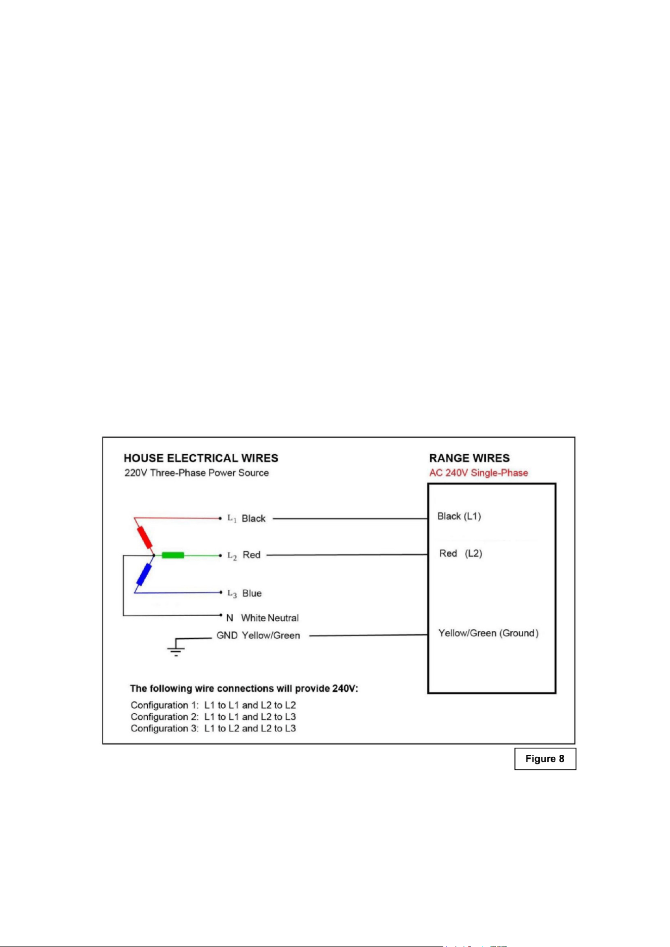
Connection of the Range Wires to the Mains
1. This appliance is equipped with the following wires:
• One black wire (L1 - Live) and one red wire (L2 - Live)
• One yellow /green (Ground)
2. Follow the diagram below to know how to connect the freestanding range wires to the electrical
main wires of the home. (See Figure 8)
3. The black and red wires can be connected to the electrical main wires of the home in one of the
following three congurations:
• Configuration 1: L1 to L1 and L2 to L2
• Configuration 2: L1 to L1 and L2 to L3
• Configuration 3: L1 to L2 and L2 to L3
5. Never use reductions, shunts, or adaptors which can cause overheating or burning.
6. After carrying out the connection to the mains, check that the supplying cable does not come
into contact with parts subject to heating.
15
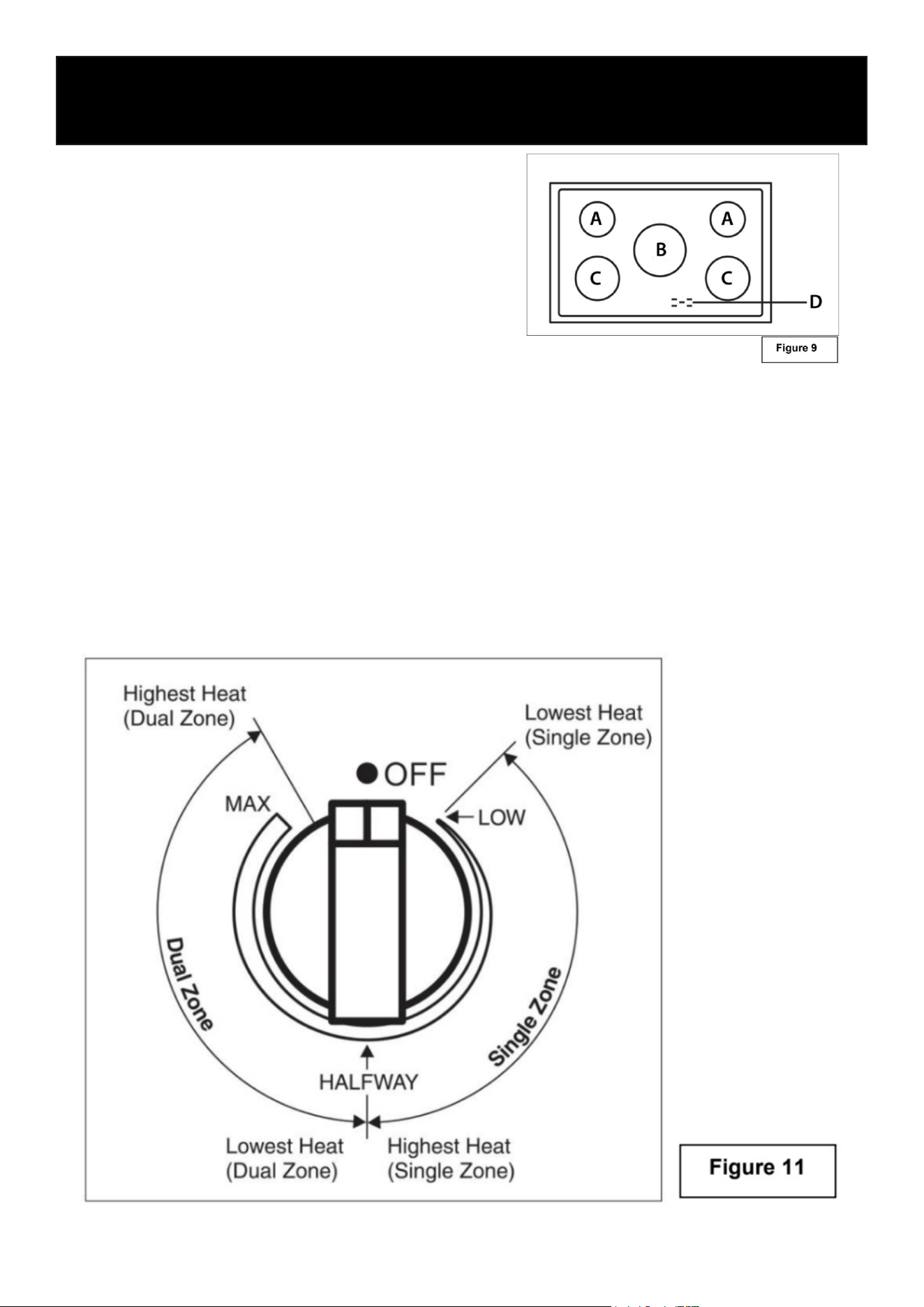
Surface Cooking
Location of the Burners
A. Single cooking zone - 1200W
B. Single cooking zone - 2500W
C. Single cooking zone - 1800W
D. Power & Residual Heat Warning Lights
Before First Use:
• Before using the appliance for the rst time, clean the ceramic glass surface thoroughly. Re-
move any labels, packaging materials, or protective lm.
• Place a saucepan lled with water on each of the front burners and turn them on High for
about 30 minutes.
• After 30 minutes, turn off the front burners. Then place a saucepan of water on each of the rear
burners and the center burner, and turn them on High for another 30 minutes.
• This initial heating process allows any protective oils or moisture from manufacturing to evap-
orate and ensures the electronic control circuits function properly.
Using the Temperature Control Knob
Operation
16
• Turn the control knob to the desired position (low to high). (See Figure 11)
• Adjustment is continuous so the cooking zone will operate at any intermediate setting between
low and high.
• Once the cooking zone is hot, the LED corresponding to the zone illuminates.
• To switch off the cooking zone by turning the knob, in either direction to the “OFF” position.
• The residual heat warning light remains illuminated when the temperature of the ceramic glass
surface is hot and will switch off once the surface temperature has cooled.
Guidelines for Surface Cookware
Do not place plastic items such as salt and pepper shakers, spoon holders, or plastic wrap-
ping on top of the appliance while it is in use. These items can melt or catch re. Potholders,
towels, or wooden utensils may also ignite if placed too close to a heat source.
Note: Always use cookware and utensils only for their intended purpose, and follow the manu-
facturer’s instructions. Some materials are not designed for use in an oven or on a cooktop.
• For best results and energy eciency, use only cookware suitable for electric cooking.
• The bottom of the pan should be thick and completely at.
• Before placing cookware on the burner, make sure both the pan and burner are clean and dry.
• To prevent scratching the ceramic glass surface, never use cast iron cookware or pans with
rough bottoms.
Pot Sizes:
• To avoid wasting energy, ensure the bottom of the pan is no more than ¾ inch larger than the
circle marked on the cook-top.
• The pot sizes listed in the table below are recommended for your ceramic surface. Solid pots
and pans with at bottoms provide the most ecient cooking performance. (See Figure 9.)
Burner Zone Zone Diameter Minimum Diameter of Pan
Cooking Zone A
Cooking Zone B
Cooking Zone C
5
1/2
inches
8
7/8
inches
7 inches
6
1/2
inches
9
13/16
inches
7
7/8
inches
17
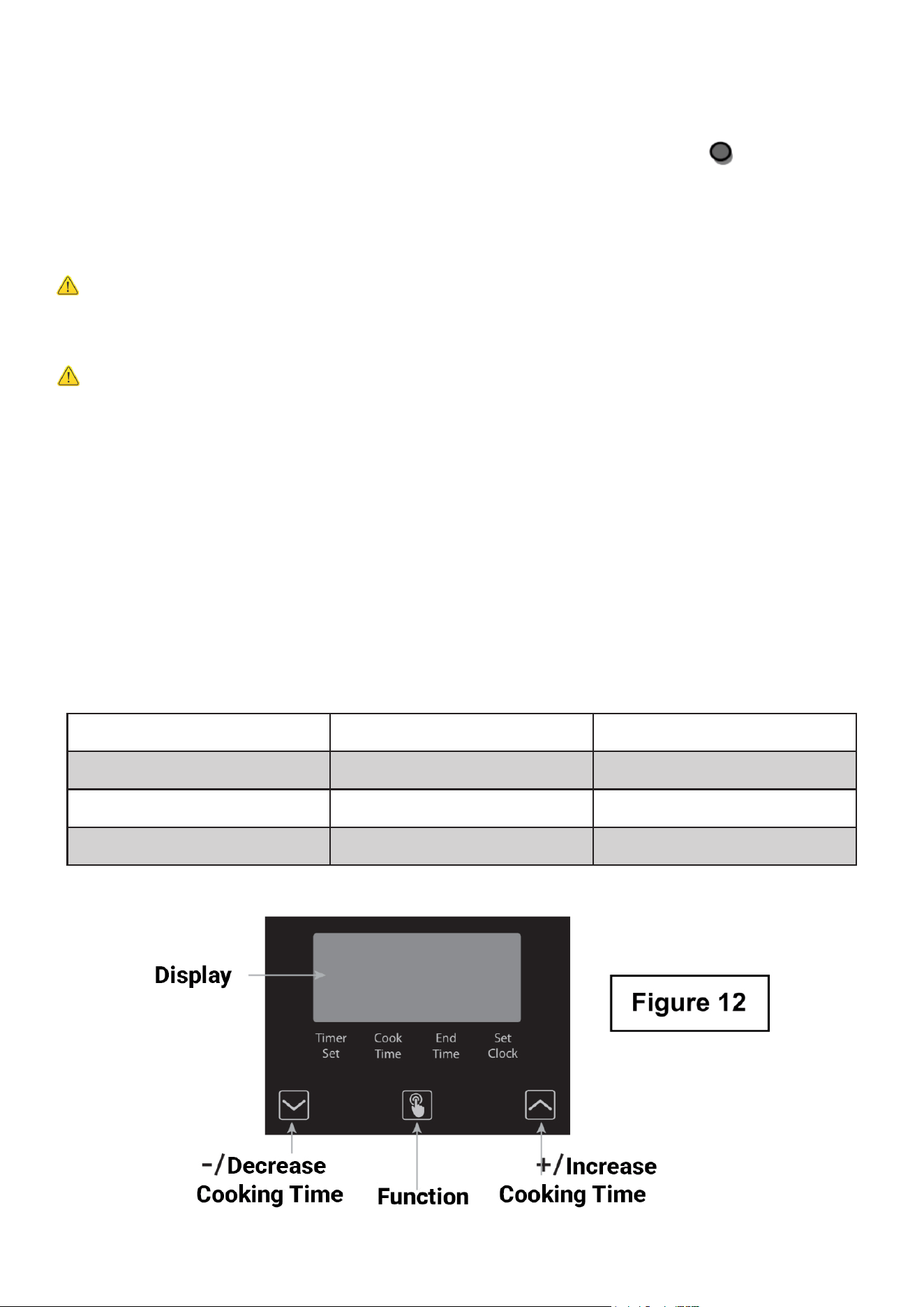
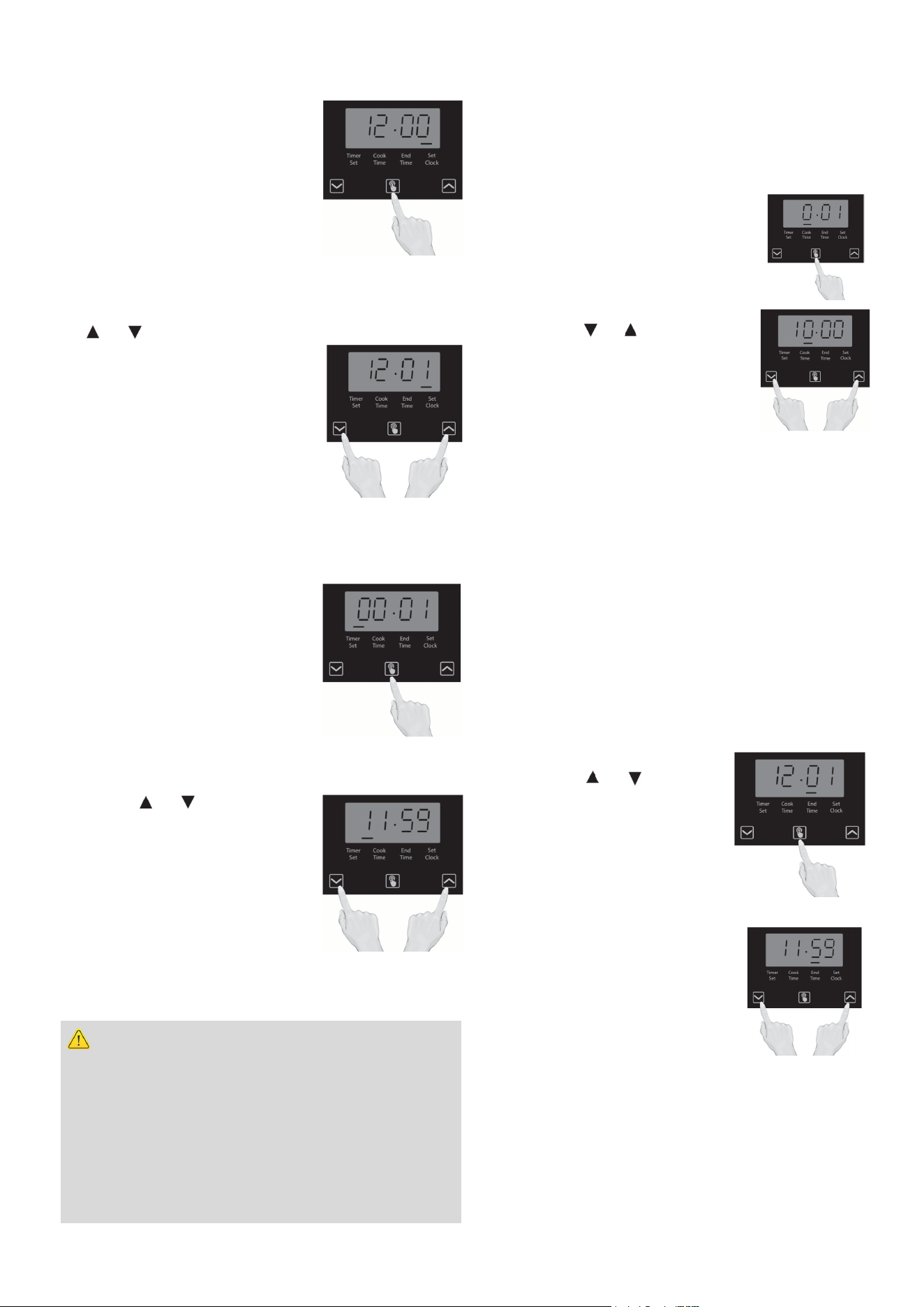
Setting the Clock
1. When rst connected to AC
power or after a power outage,
the display will blink “12:00”
and the clock indicator will
ash. To enter Time Setting
mode manually, press and
release the Function button
until the clock indicator blinks.
2. To set the correct time, press
the or button to move forward or backward
until the correct time is
displayed. When nished, press
the Function button, or wait ve
seconds — the time will then be
set automatically.
Important: The clock must be
set before any oven functions can operate.
Setting the Timer
1. Press the Function button
once to enter Timer Setting
mode. The timer indicator will
light up.
2. Use the or button to set
the desired time by moving
forward or backward. The timer
will begin counting down and
will beep when the set time has
elapsed.
Warning
Use caution when using the timed cooking fea-
ture. It should only be used when cooking cured
or frozen meats, or most fruits and vegetables.
Do not use this function for foods that can spoil
easily, such as milk, eggs, fish, meat, or poultry.
Eating spoiled food can cause illness from food
poisoning.
Oven Cooking
Oven Timed Cooking - Delayed Start Timing
To begin cooking at a later time, set the Timer
to the desired delay before selecting the oven
function and temperature.
1. Press and release the Function
button until the Start indicator
blinks.
2. Press the or button to set
the desired delay time
(up to 10 hours).
3. Set the Temperature and
Cooking knobs as desired, then place the food
in the oven.
Note: The oven will not start until the pro-
grammed start time is reached.To start cook-
ing immediately, cancel the delay start func-
tion.
Programing the End Timing
To set when cooking will automatically stop:
1. Press the Function button until the End indi-
cator blinks.
2. Press the or button to
set the desired end time
(up to 11 hours and 59
minutes), then press the
Function button again to
conrm.
3. When the set time is
reached, the oven will beep.
Turn both the Temperature
and Cooking knobs to OFF,
then press the Function
button to stop the beeping.
18
Setting Oven Controls
• Turn the control knob clockwise to select the desired cooking temperature.
• The indicator light will illuminate while the oven is heating.
• Once the oven reaches the set temperature, the light will turn off.
• The light will ash periodically to indicate that the oven is maintaining the programmed tem-
perature.
Oven Light Indicator
The lamp of the oven is on. During oven operation the lamp will always remain on.
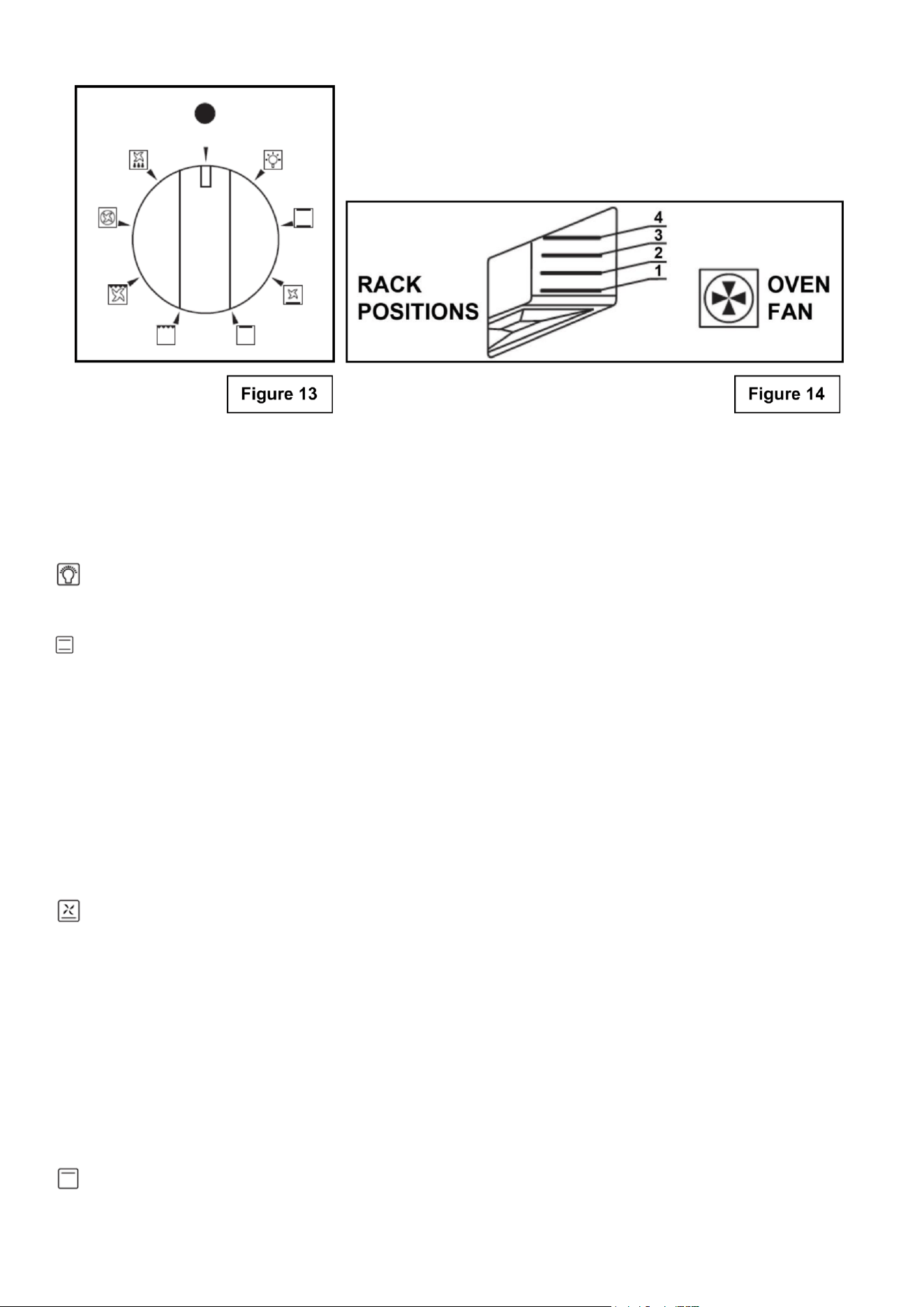
Traditional Cooking (Upper and Lower Elements)
Thermostat Selector Knob: 140°F to MAX
In this mode, heat is generated by both the upper and lower heating elements. Preheat the oven
before placing food inside for best results.
Traditional, or static cooking, provides excellent results for cakes, pizzas, bread, and the slow
cooking of casseroles.
Cooking Characteristics:
Heat is distributed evenly from the top and bottom elements.
Cooking should be done on the middle rack for uniform results.
Place dishes centrally within the oven for optimal heat circulation.
Delicate Cooking (Lower Element and Fan)
Thermostat Selector Knob: 140°F to MAX
This mode is ideal for pastries and cakes with moist toppings, low-sugar desserts, and delicate
baked goods prepared in molds.
It is also excellent for nishing dishes that require extra heat on the bottom, or for recipes that
need gentle, even baking from below.
Cooking Characteristics:
Heat is generated from the lower heating element and evenly distributed by the fan.
Provides gentle, consistent heat — perfect for delicate textures.
For best results, place the baking tray on the bottom rack level.
Broil / Top Heat (Upper Element Only)
Thermostat Selector Knob: 140°F to MAX
This mode is ideal for browning or nishing dishes at the end of the cooking process.
It provides intense top heat, giving foods a golden, crisp surface without overcooking the interior.
Tip: For best results, place the dish on the upper rack level and monitor closely to prevent
over-browning.
Grill Cooking (Grill Element)
Thermostat Selector Knob: 140°F to MAX
This mode is ideal for browning, toasting, or nishing dishes at the end of cooking.
The grill element provides intense, direct heat from above, creating a crisp, golden surface while
preserving tenderness inside.
Fan-Assisted Grill Cooking (Grill Element and Fan)
Thermostat Selector Knob: 140°F to 392°F
This mode is best used for grilling meats, vegetables, and poultry.
Preheat the oven, then place the food on a grill rack or baking tray and position it on the middle
oven rack.
Multiple racks can be used at the same time when cooking with this method.
Convection Cooking (Heating Element and Fan)
Thermostat Selector Knob: 140°F to MAX
This mode provides even heat distribution throughout the oven, allowing for multi-rack cooking of
various dishes at the same time.
Preheat the oven before placing food inside.
Use the “Fan Forced” function to activate this cooking mode.
Defrost (Bottom Fan)
All types of food can be defrosted by circulating air at room temperature, such as cakes, cream, or
fruit.
For items like meat, sh, and bread, set the thermostat between 347°F–392°F for faster, controlled
defrosting.
Suggested Cooking Instructions:
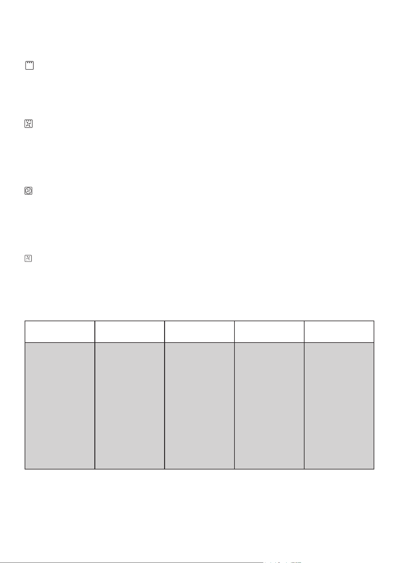
Setting: Food:
Rack Level
(See Figure 13)
Temperature
(Fahrenheit):
Time (mins):
Traditional
Cooking
(add time for
preheat)
Lasagna
Oven-Baked Pasta
Roast Veal
Beef
Pork
Chicken
Duck
Goose/Turkey
Lamb
Fish
Pizza
Short Pastry
Fruit Cake
Browning
2-3
2-3
2
2
2
2
2
1
2
1-2
1-2
1-2
1-2
3-4
410-450
410-450
350-400
410-460
340-400
340-400
340-400
280-340
340-400
340-400
410-450
340-400
340-400
140
30
40
30-40/lb
30-40/lb
30-40/lb
45-60
45-60
45-60
15/lb
Depends on dimension
40-45
15-20
20-30
5
19
20
Setting: Food:
Rack Level
(See Figure 13)
Temperature
(Fahrenheit):
Time (mins):
Convection
Cooking
(add time for
preheat)
Lasagna
Oven-Baked Pasta
Roast Veal
Beef
Pork
Chicken
Duck
Goose/Turkey
Lamb
Fish
Pizza
Sponge Cake
Fruit Cake
Bread
2-3
2
2
2
2
2
2
2
2
2-3
2-3
2-3
2-3
1-2
375-410
375-410
300-350
350-375
300-325
350
325-350
300-325
300-350
300-350
410-475
375-425
350-375
425-475
20-25
25-30
65-90
65-90
70-100
70-90
100-160
160-240
100-130
Depends on dimension
30-50
25-35
40-50
7
Setting: Food:
Rack Level
(See Figure 13)
1
st
Side Cook
Time (mins):
2
nd
Side Cook Time
(mins):
Grill Cooking
Pork Chops
Fillet (Pork)
Fillet (Beef)
Liver
Veal
Chicken
Sausages
Meatballs
Fish Fillet
Toast
4
3
3
4
4
3
4
4
4
4
7-9
9-11
9-11
2-3
7-9
9-14
7-9
7-9
5-6
2-4
5-7
5-9
9-11
2-3
5-7
9-11
5-6
5-6
3-4
2-3

21
Inside Oven
• This appliance does NOT have a self-cleaning feature.
• DO NOT attempt to clean the appliance whenever the oven is still hot.
• Use an appropriate cleaning product designed specically to clean the inside of ovens.
• IMPORTANT: Always follow label instructions on cleaning products.
Storage Drawer
• Make sure drawer is cool and empty before cleaning.
• Use a mild detergent.
Oven Door Exterior
• Use a glass cleaner and a soft cloth or sponge.
• Apply glass cleaner to soft cloth or sponge, not directly on panel.
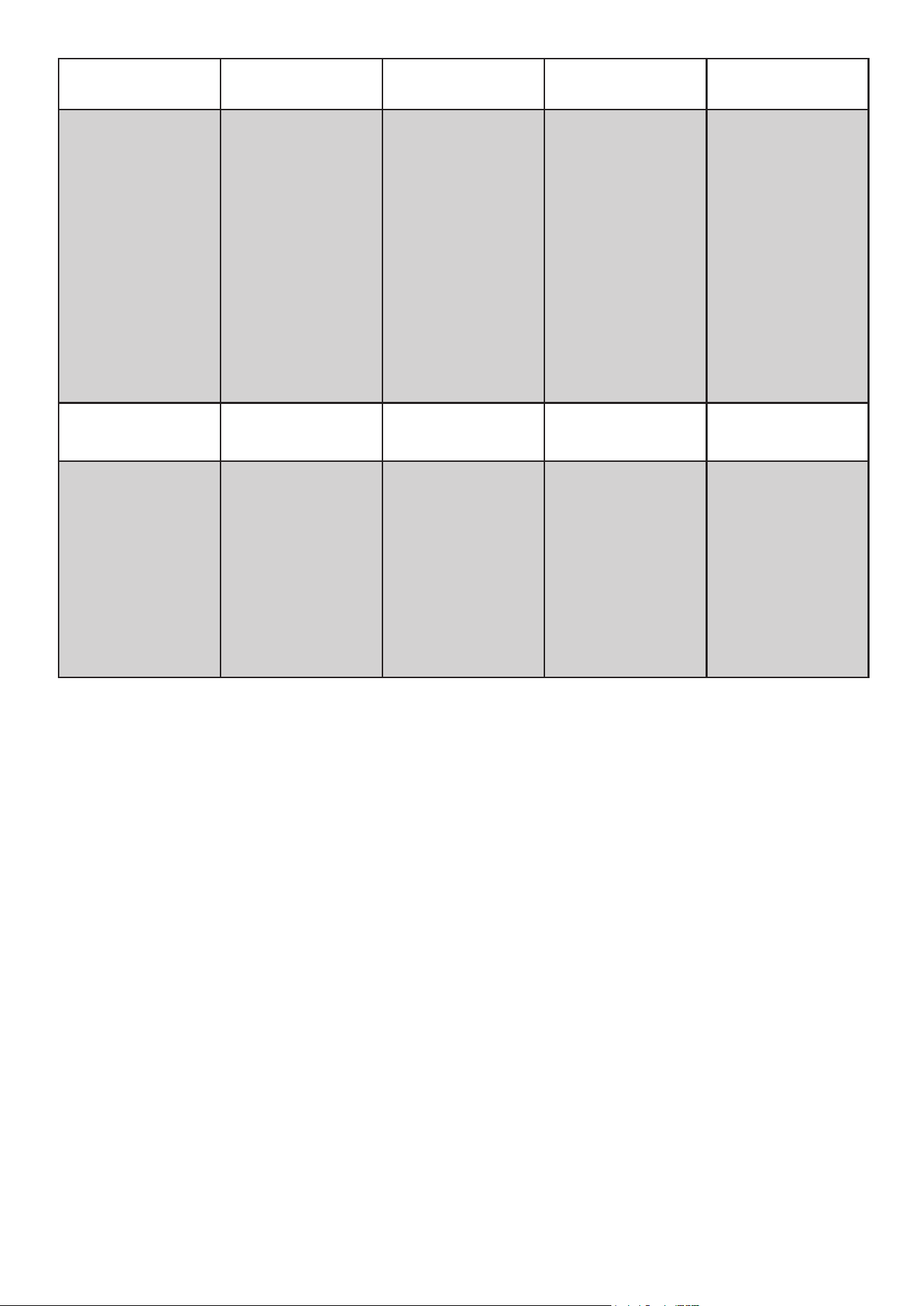
Removing and Cleaning the Oven Door
For normal use, it is not recommended to remove the oven door. However, if removal is necessary,
make sure the oven is turned off and completely cool. The oven door is heavy, so handle it careful-
ly and follow the steps below.
Open the door fully.
• Lift up and push the small levers located on both hinges all the way back.
• While holding the door rmly on both sides, close it slowly until it touches the levers.
• Continue closing the door until it is about 4 inches (10 cm) from being fully closed.
• Pull the door toward you to remove it from the hinge slots. The door will come away from the
oven gently. (See Figure 15.)
Care and Cleaning
Warning
Electrical Shock Hazard
Burn Hazard
To avoid possible burns use care when cleaning the appliance.
DO NOT attempt to clean the appliance whenever the oven or heating elements are still hot.
To avoid possible burns DO NOT attempt any of the following cleaning instructions
before turning OFF ALL of the heating elements and allowing them to cool.
Important: Always follow label instructions on cleaning products.
Control Knobs
• For general cleaning, use hot, soapy water and a cloth.
• For more dicult soils and built-up grease, apply a liquid detergent directly onto the soil. Rinse
with a damp cloth and dry.
• DO NOT use steel wool or acidic cleaners on the knobs as they can scratch.
Stainless Steel
• Clean stainless steel with hot, soapy water and a dishcloth. Rinse with clean water and a cloth.
• Do not use cleaners with high concentrations of chlorides or chlorines. Do not use harsh scrub-
bing cleaners. Only use kitchen cleaners that are especially made for cleaning stainless steel.
Maintenance
22
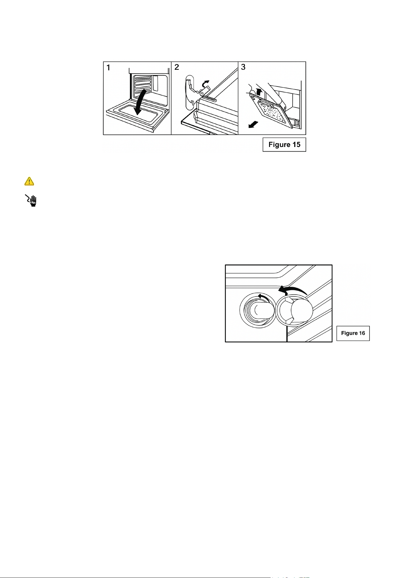
Changing the Interior Oven Light Bulb
Warning
Electrical Shock Hazard
• Ensure that the appliance is switched off before replacing the lamp to avoid possible electric
shock.
• Remove the glass cover by turning counter clockwise. (See Figure 16)
• Replace bulb with a high temperature bulb able to withstand 600 degrees and that meets the
following criteria:
• 240V
• 25W
• Type: E-14
• To reinstall the door, reverse the above procedure.
Note: If the door does not come away easily, do not force it. Check that the hinge levers are fully
open before attempting removal again.
Troubleshooting
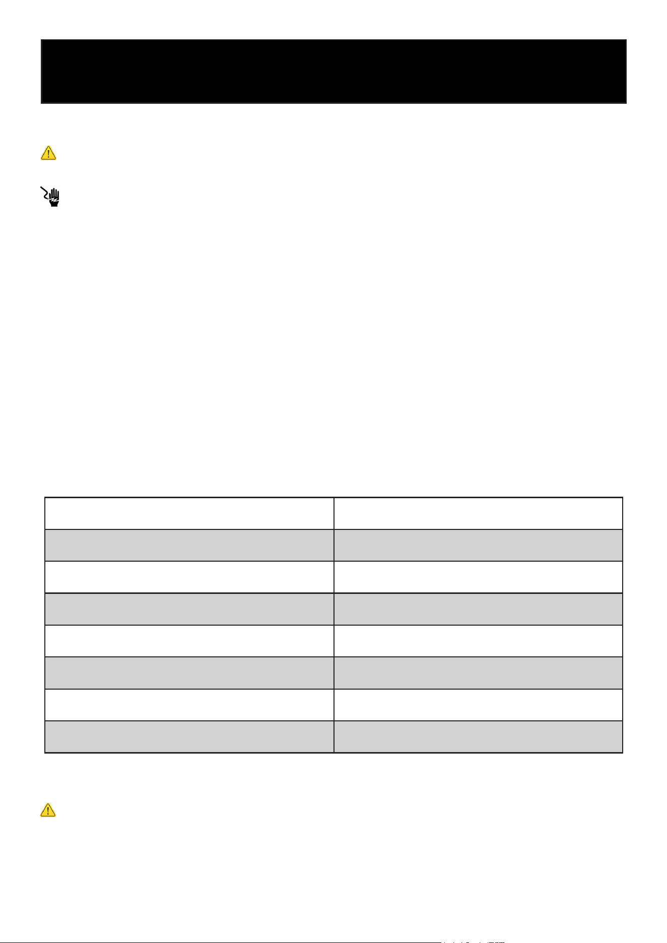
Problem Possible Cause Recommended Action
Appliance Fails to
Operate
• Is the electrical supply discon-
nected?
• Household fuse blown or cir-
cuit breaker tripped?
• Verify that electrical wires are connected to
the mains properly. See “Electrical Con-
nection” section. If the problem continues,
contact a qualied technician.
• Replace the fuse or reset the circuit breaker.
If the problem continues, contact a qualied
technician.
Surface Burners Will
Not Operate
Is the control knob set correctly?
Push in knob before turning to a setting.
Excess Heat Around
Cookware on Cooking
Surface
Is the cookware the proper size?
Use cookware about the same size as the
heating element. Cookware should extend 0.79
inches outside the cooking area.
Cooktop Cooking Re-
sults Not as Expected
• Is the proper cookware being
used?
• Is the control knob set to the
proper heat level?
• Is the range level?
• See “Surface Cooking Utensils” section.
• See “Setting Surface Controls” section.
• Level the range. See the “Unpack Range
/ Install Leveling Feet and Back Panel”
Oven Will Not Operate
• Are the oven controls set cor-
rectly?
• Cooling Fan Runs During Bak-
ing and Broiling
• See “Setting Oven Controls” section.
• It is normal for the fan to automatically run
while the oven is in use and for some time
after as well.
Oven Temperature Too
High Or Too Low
• Was the oven preheated?
• Are the racks positioned prop-
erly?
• Is there proper air circulation
around bakeware?
• Is the batter evenly distributed
in the pan?
• Is the proper length of time
being used?
• Has the oven door been opened
while cooking?
• Are baked items too brown on
the bottom?
• Are pie crust edges browning
early?
• See “Cooking Instructions” section.
• Adjust cooking time.
• Opening the oven door while cooking lets
heat escape, which can increase cooking
time.
• Move rack to higher position in the oven.
• Use aluminum foil to cover the edge of the
Important
Before contacting customer service, review the information below. Many issues can be easily
resolved without a service call. These examples describe normal operating conditions and do not
indicate a product defect.
23

24
LIMITED WARRANTY
KoolMore Supply Inc. extends a limited warranty to the original purchaser, guaranteeing that this KoolMore product is
free from manufacturing defects in material or workmanship for one year from the date of purchase.
Should you discover any such defect within the warranty period, KoolMore Supply Inc. reserves the right to repair or re-
place the product without charge, or to cover the cost of replacement parts and repair labor needed to correct defects
present at the time of purchase or resulting from regular usage, when the appliance has been installed, operated, and
maintained as per the instructions provided.
At its sole discretion, KoolMore Supply Inc. may decide to replace the product. In such an event, your replacement
appliance will carry the warranty for the remaining term of the original unit’s warranty period.
This warranty is valid exclusively to the original purchaser of the product and only applicable within the United States.
The warranty commences from the date of original consumer purchase. Proof of the original purchase date will be
required to obtain service under this warranty.
Under this limited warranty, your sole and exclusive remedy will be product repair, as outlined above. All services must
be provided by a KoolMore designated service company.
To claim warranty or request repair service:
Email [email protected]. Please include your name, address, phone number, warranty repair request, and a copy
of your proof of purchase receipt. Alternatively, visit koolmore.com and use the Contact Us page. A KoolMore custom-
er service representative will promptly arrange service for your appliance.
We thank you for choosing KoolMore.
WARRANTY EXCLUSIONS
This limited warranty will not cover:
1. Failure of the product to perform during power failures or interruptions,
or due to inadequate electrical service.
2. Damage incurred during transportation or handling.
3. Damage caused by accidents, vermin, lightning, winds, re, oods, or acts of God.
4. Damage resulting from accidents, alterations, misuse, abuse, improper installation, repair, or maintenance. This
includes using any external device that alters or converts the voltage or frequency of electricity.
5. Unauthorized product modications, repairs by unauthorized centers, or use of non-approved replacement parts.
6. Abnormal cleaning and maintenance not aligned with the user’s manual.
7. Use of incompatible accessories or components.
8. Any costs associated with repairs or replacements under these excluded circumstances shall be the responsibility
of the consumer.
WARRANTY