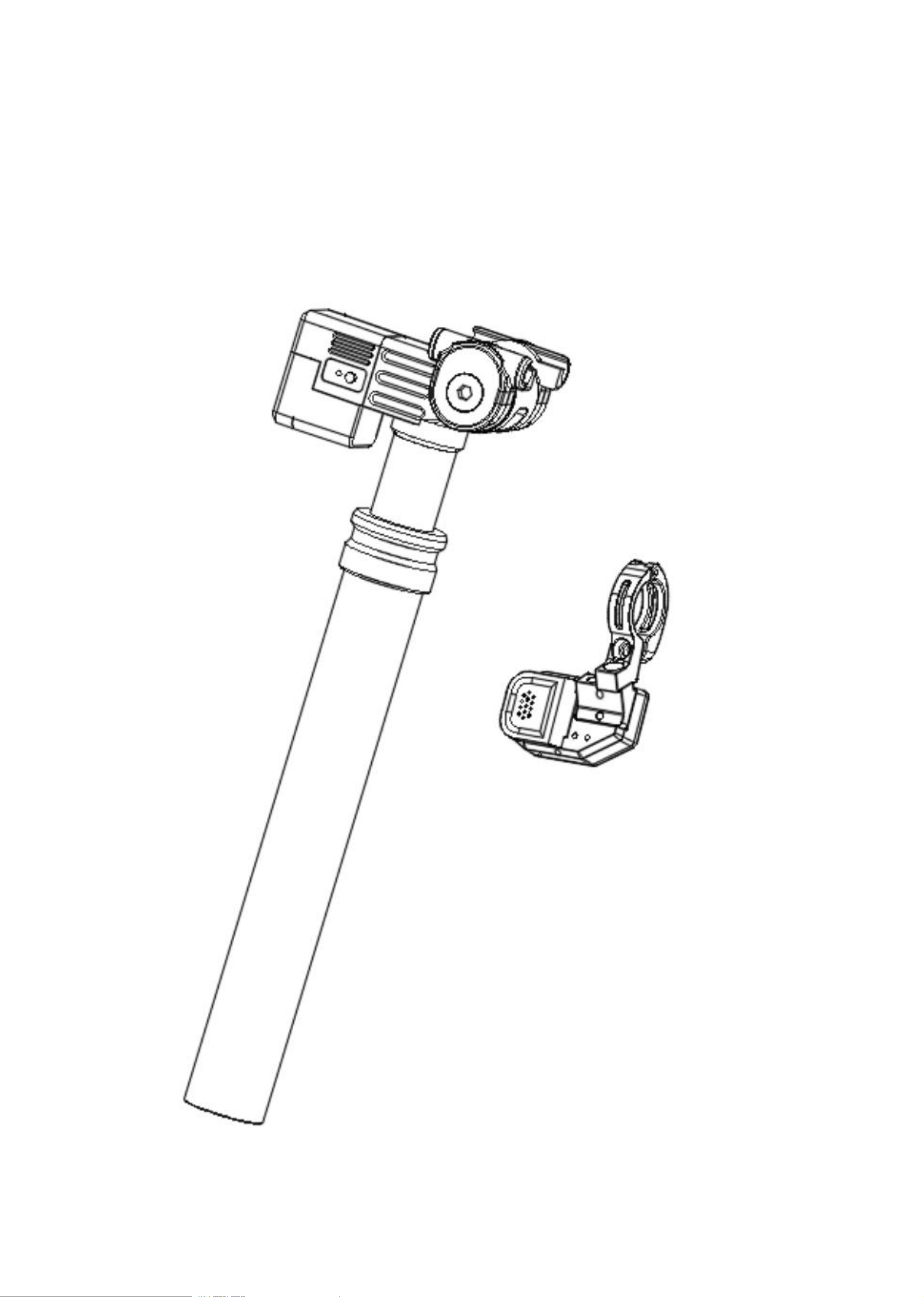
SMART DROPPER
operating instruction
Before using the product,please read the manual carefully and follow the relevant precautions to
ensure the best performance of the equipment and avoid dangerous or illegal situations.
2
A
–
Warning and Safety Information
1.Electrically controlled seatpost products must be installed by qualified bicycle maintenance technicians in accordance with
the official installation specifications for electric seatposts. Improper installation may cause malfunctions, lead to loss of
bicycle control, and result in serious personal injury or even death.
2.Modifying or altering an electronically controlled seatpost product may cause it to malfunction, potentially resulting in
serious injury or even death. Do not modify or alter any part of the electronically controlled seatpost product.
3. Improper maintenance or the installation of non-ECU seat tube replacement parts on an ECU seat tube product may cause
the product to malfunction, resulting in serious personal injury or even death. Do not use high-power cleaners to clean the ECU
seat tube product. The included dial contains a button battery. The only compatible battery type is the CR2032 (nominal battery
voltage: 3 V).
4. Keep new and used batteries out of reach of children. Do not swallow batteries, as they pose a risk of chemical burns. If a
button battery is accidentally swallowed, it can cause severe internal burns within just two hours and may lead to serious
personal injury or even death. If you believe that a battery has been swallowed or has entered any part of your body, seek
medical attention immediately. Please call your local Poison Control Center for information on appropriate treatment. If the
battery compartment is not securely closed, stop using this product and keep it out of reach of children; failure to do so may
result in serious personal injury or even death.
5. Please remove and immediately recycle or dispose of used batteries in accordance with local regulations; store used batteries
out of reach of children. Batteries should not be disposed of together with household waste, nor should they be incinerated.
Even used batteries can cause serious injury or even death. Non-rechargeable batteries should not be recharged. Do not forcibly
discharge, recharge, disassemble, heat (above the rated temperature specified by the manufacturer), or incinerate these batteries;
otherwise, air release, leakage, or explosion may cause chemical burns, resulting in personal injury.
6. Ensure that the positive and negative terminals (+ and –) of the battery are correctly oriented after installation. Do not mix
new and old batteries, nor mix batteries of different brands or types (e.g., alkaline batteries, carbon-zinc batteries, or
rechargeable batteries). In accordance with local regulations, remove any batteries that have not been used for an extended
period from the device and recycle or dispose of them immediately. Always securely fasten the battery compartment. If the
battery compartment is not securely closed, stop using this product, remove the battery, and keep it out of reach of children.
7. Ensure that operating the electric control seat post does not interfere with the normal operation of the brake or the gear shift
lever. If such interference occurs, it may cause the bicycle to lose control, resulting in serious injury or even death.
8. Before using the SEEKRuN seatpost during ridirg. practice using it in a safe and controlled environment tofullyunderstand
its functions Sudden and unexpected movement of the saddle may cause you to lose controlof the bicycle, leading to serious
injury or death.
9.Press the remote button when you want to adjust the saddle height When lowering the saddle, press downon it with your body;
when raising the saddle back to a higher position, guide it wth your body. Release theremote button once the seatpost reaches
your desired position. Always release the remote button first beforeremoving body pressure from the saddle. Before using the
SEEkRuN seatposttortechnically demanding ndingscenarios, practice within your abilityto acquire professional sklls in
operating the SEEKRuN seatpost.
10.Important: Change or modifications not expressly approved by the manufacturer responsible forcompliance could void the
user's authority to operate the equipment.
11.This device complies with part 15 of the FCC Rules. Operation is subject to the following two conditions: (1)This device
may not cause harmful interference, and (2) this device must accept any interference receivedincluding interference that may
cause undesired operation.
▲
WARNING
· INGESTION HAZARD:This product contains a button cell or coin battery.
· DEATH or serious injury can occur if ingested.
· Aswallowed button cell or coin battery can cause Internal Chemical Burns in as
little as 2 hours.
· KEEP new and used batteries OUT OF REACH of CHILDREN
· Seek immediate medical attention if a battery is suspected to be
swallowed or inserted inside any part of the body.
3
1. Please refer to your bicycle user manual. Electrically controlled stem products must be installed by a certified professional
bicycle technician in accordance with the official installation specifications for electric stems. Improper installation of electric
stem products may cause malfunctions, lead to loss of bicycle control, and result in serious personal injury or even death.
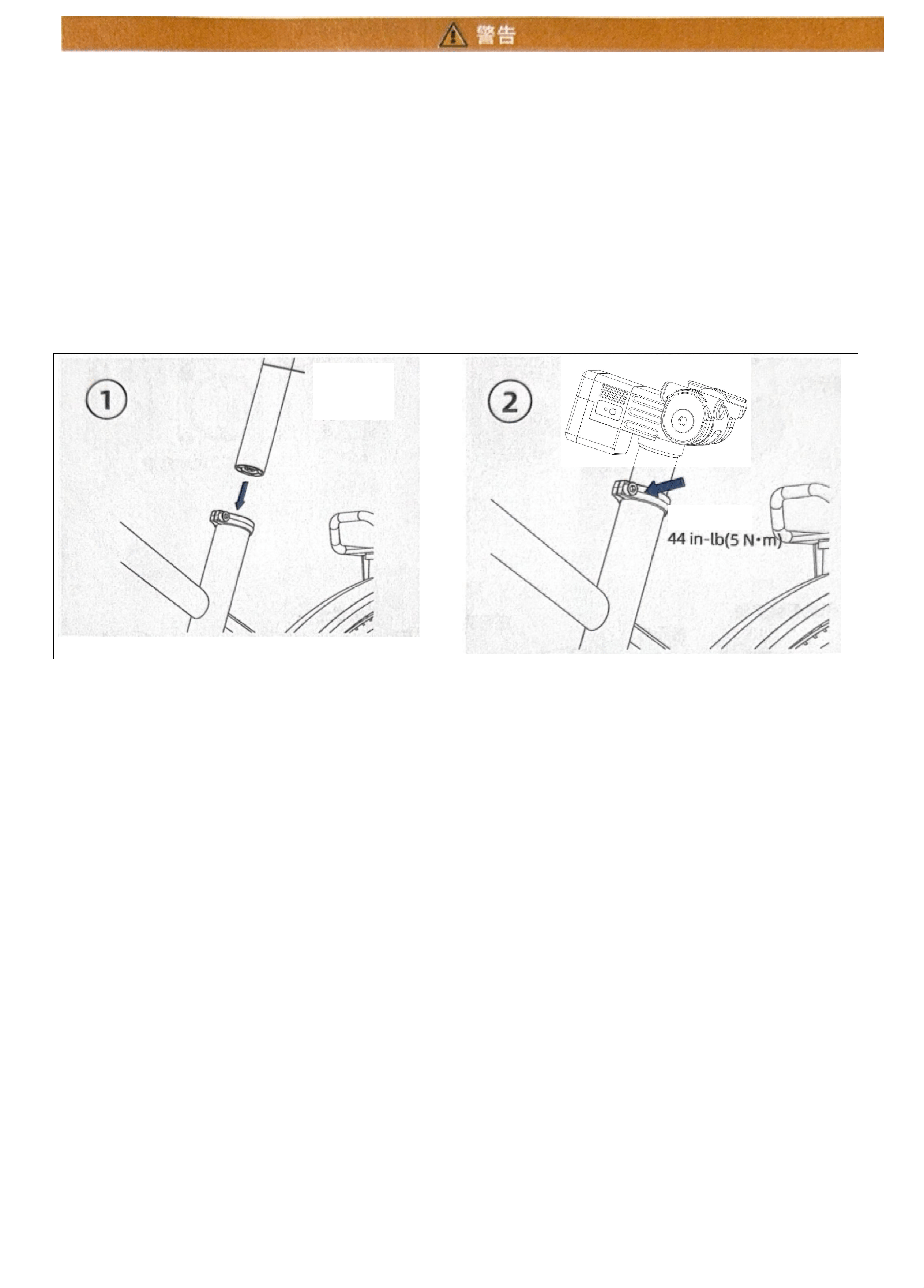
2. Install the seat post into the frame with the correct orientation (for carbon fiber frames, apply a slip-prevention compound as
needed). Ensure the seat post extends beyond the minimum insertion depth mark on your seat post.
3. The electrically controlled seat tube has a directional orientation. When oriented correctly (with the battery facing backward),
use the push-button function to check whether the seat tube can move freely to all positions.
4. Set the base pipe to the desired height, then tighten the base pipe fastening bolt to 44 in-lb (5 N
·
m) (as shown in
the figure). After insertion, ensure that the "Minimum Insertion Depth Mark" on the base pipe extends beyond the
base pipe fastening bolt (as shown in the figure). Again, verify that the base pipe can be moved freely to all
positions.
5. The maximum torque value for the electrically controlled seat post tightening bolt is 44 in·lb (5 Nm). The actual required
torque depends on the rider's weight and the bicycle frame.
As well as the type or brand of the seat tube clamp. The correct torque will properly support the rider without interfering
with the seat tube's functionality. If the torque is too high, the seat tube may not fully retract from any position or may not
move up or down smoothly. If the torque is too low, the seat tube may not adequately support the rider's weight or may fail
to remain stationary on the seat tube. Improper torque applied at the seat tube clamp connection can cause the bicycle to
lose control, resulting in serious injury or even death.
6. Regardless of the original configuration of the bicycle frame tube, to achieve optimal structural support, you should insert the
electrically controlled seat tube at least into the lowest insertion mark on the seat tube and into the minimum insertion point
specified by the bicycle frame manufacturer. Failure to adhere to these two requirements poses a risk of damaging the frame or
the seat tube, which could result in serious personal injury or even death.
Minimum
insertion
depth line
Tighten to
03
4
Note: All images in this manual are schematic diagrams; they may differ slightly from the actual
product – please refer to the actual product for accurate information.
PRODUCT INTRODUCTION
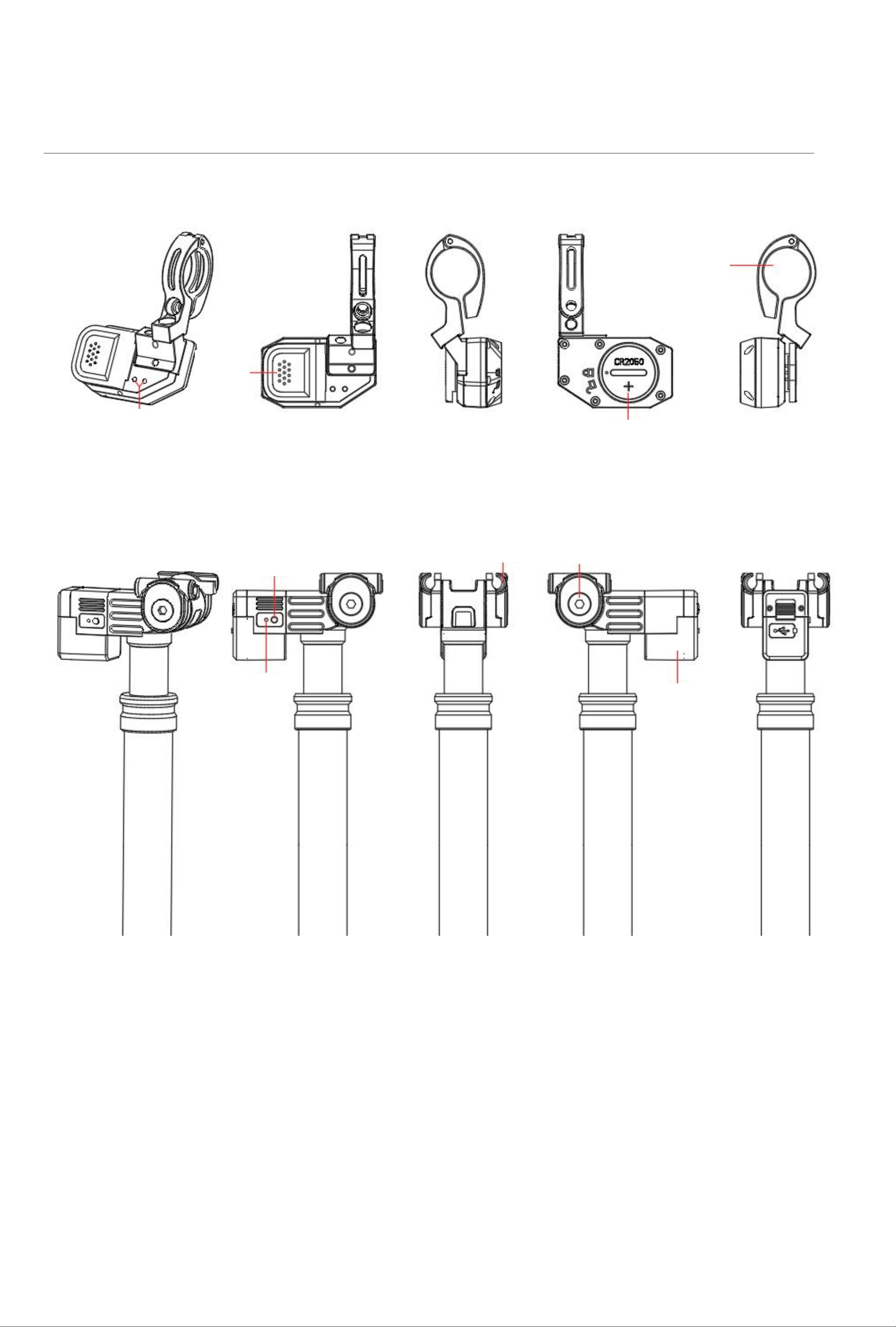
BLUETOOTH REMOTE
WIRELESS DROPPER SEATPOST
Clamp ring
Battery
Control
button
Indicator
Indicator
Control button
Battery
addle clamp
Saddle clamp screw
04
5
Note: All images in this manual are schematic diagrams; they may differ slightly from the actual product – please refer
to the actual product for accurate information.
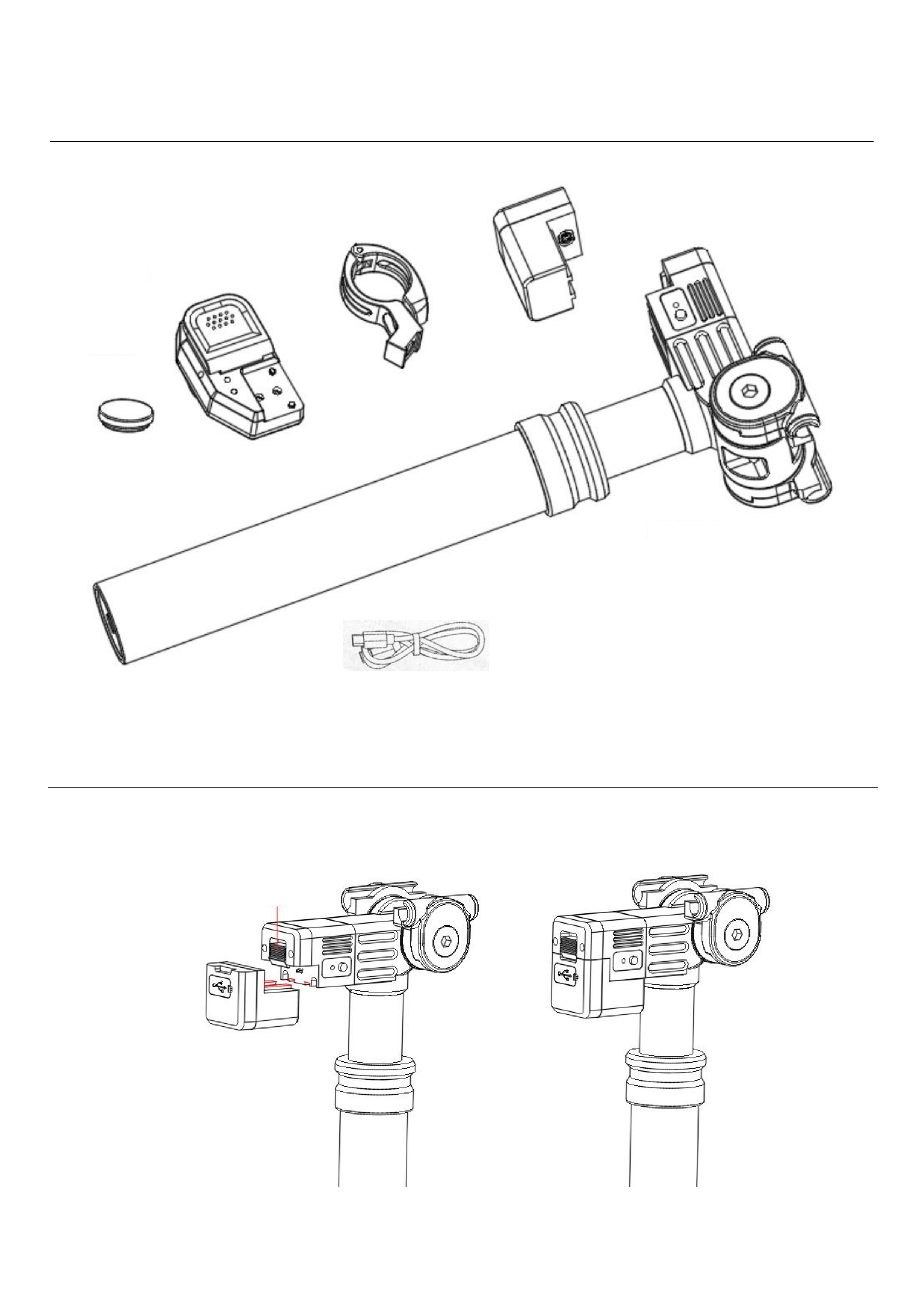
Component List
S e a t T u b e & B l u e t o o t h B u t t o n B a t t e r y I n s t a l l a t i o n
Coin cell battery
(cr2032)
Seatpost battery
Remote clamp ring
Charging base
Wireless Dropper Seatpost
Electric control seat tube battery installation
1.Pull the slider to align the
battery slot with the red slot
and push it to the bottom.
2.Release the slider, the
slider moves downward, and
the battery is locked in place.
slider
06
6
Note: All images in this manual are schematic diagrams; they may differ slightly from the actual product – please refer to the actual product
for accurate information.
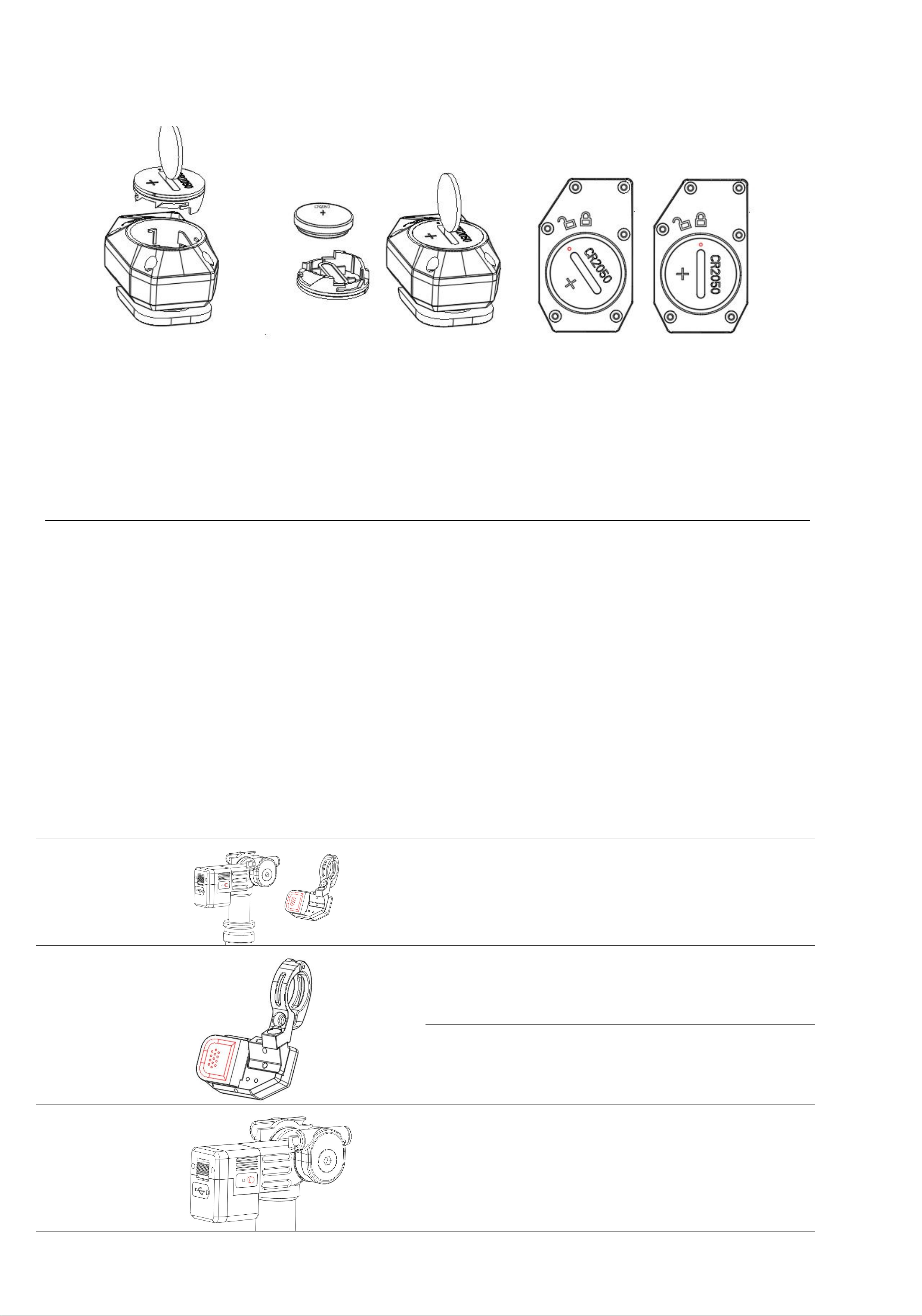
Note: The keypad is powered by a CR2050 button cell battery; the keypad is powered by an already
installed CR2050 button cell battery. The side marked with the "+" symbol indicates the positive terminal of the
battery.
function Introduction
1. Bluetooth pairing: Hold the seat control button for 6 seconds until the red indicator light starts flashing; then
hold the controller button for 6 seconds until the red indicator light starts flashing. Both devices will enter
pairing mode. Once pairing is successful, the hand indicator light will stop flashing – this indicates that pairing
has been completed. Alternatively, you can hold both the seat control button and the controller button
simultaneously for an extended period, and the red light will flash to initiate pairing; once the flashing stops,
pairing is successful. (The device is pre-paired; no re-pairing is required when replacing the battery.)
2. After 15 minutes of inactivity, the controller will automatically enter sleep mode; simply press the button
briefly to power it on and resume normal operation;
3. The seat pipe enters a sleep mode automatically after 90 minutes of inactivity;
4. Resume seat pipe sleep mode: Press and hold the controller's button six times to wake it up; the device will
then function normally.
5. Turn off the device, install the battery, and it will be ready for use.
Button Functions:
Bluetoothpairing
Longpressfor6seconds
(Red light flashing)
Bluetoothpairingmode
Controller
Button
Hold down
(No more than 6 seconds, it will
enter Bluetooth pairing)
Turn on Journey Adjustment
(BlueLight)
Release
Close the travel adjustment / lock
theseatpost
Seat post button
Hold down
(No more than 6 seconds, it will
enter Bluetooth pairing)
Turnon/Closethetravel
adjustment
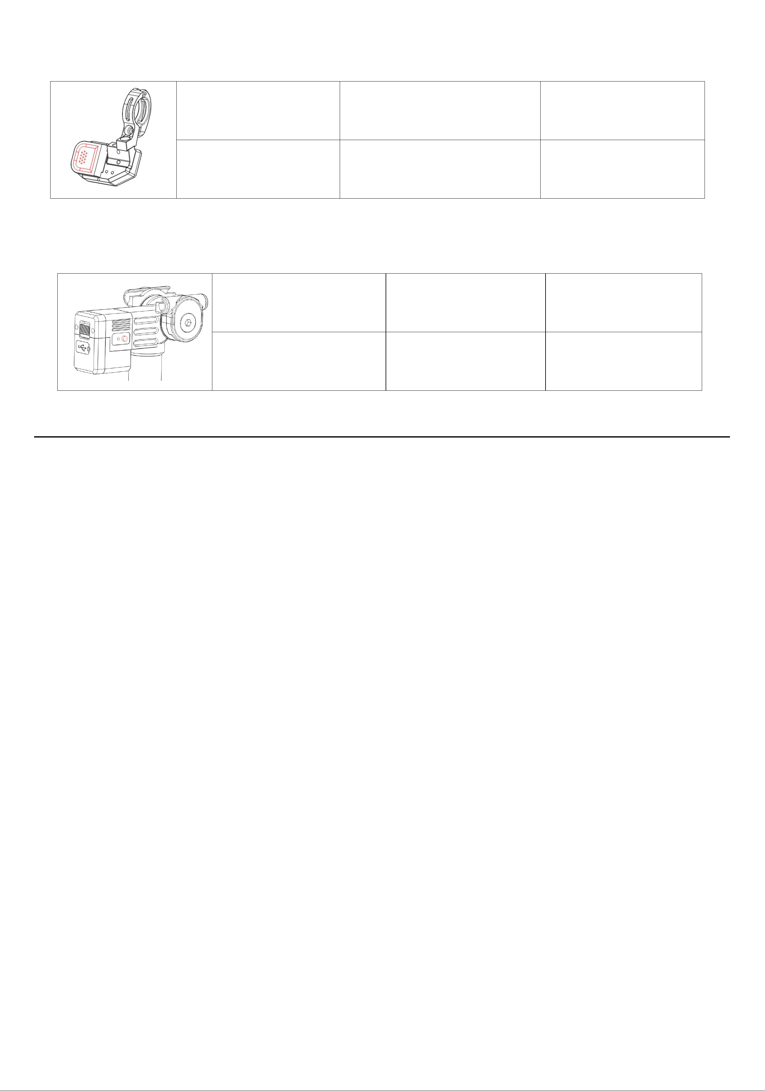
Electric control seat tube battery installation
1.Use a CR2032 battery or other
suitable toolto rotate the compartment
cover counterclockwise to remove it;
2.Insert the CR2032 battery into the battery
compartment with the positive terminal
(marked“+”)facing outward;
3.As shown in the figure, the red circle
corresponds to the locking position. Use the
appropriate tool to press and rotate the hatch
cover counterclockwise to the red circle
corresponding to the locking position.
06
7
Note: All images in this manual are schematic diagrams; they may differ slightly from the actual product – please
refer to the actual product for accurate information.
Controller Indicator Light Instructions:
Battery level> 10%
Short press the control button
Green light flashes once
B a t t e r y le v e l ≤ 2 0 %
Short press the control button
Red light flashes once
Note: To ensure optimal device performance, it is recommended to consider replacing the battery as soon as the
battery level falls below 10% (the indicator light will flash red).
Seat Pipe Indicator Light Instructions:
Note: To ensure optimal device performance, it is recommended to charge the device as soon as the
battery level drops below 20% (when the red indicator light starts flashing).
Note: 1. It is recommended that users adjust the seatpost height again based on their actual riding experience after
installation; however, please ensure that the seatpost is inserted to its minimum depth.
2. Apply the seat tube clamp to the recommended locking force (≤5 N·m). Excessive
tightening may cause excessive deformation of the lifting seat tube, potentially leading to
issues such as uneven lifting motion; therefore, do not over-tighten the clamp.
3. When the seat post will not be used for an extended period, raise it to its maximum height and
remove the battery.
FCCW ARNING
Thisdevicecomplieswithpart15oftheFCCRules.Operationissubjecttothefollowingtwo
This device complies with part 15 of the FCC Rules. Operation is subject to the following two conditions: (1)
This device may not cause harmful interference, and (2) this device must accept any interference received,
including interference that may cause undesired operation.
Note: This equipment has been tested and found to comply with the limits for a Class B digital device, pursuant
to part 15 of the FCC Rules. These limits are designed to provide reasonable protection against harmful
interference in a residential installation. This equipment generates, uses and can radiate radio frequency energy
and, if not installed and used in accordance with the instructions, may cause harmful interference to radio
communications. However, there is no guarantee that interference will not occur in a particular installation. If
this equipment does cause harmful interference to radio or television reception, which can be determined by
turning the equipment off and on, the user is encouraged to try to correct the interference by one or more of the
following measures:
—Reorient or relocate the receiving antenna.
—Increase the separation between the equipment and receiver.
—Connect the equipment into an outlet on a circuit different from that to which the receiver is connected.
—Consult the dealer or an experienced radio/TV technician for help.
Note: The Grantee is not responsible for any changes or modifications not expressly approved by the
party responsible for compliance. such modifications could void the user's authority to operate the equipment.
The device has been evaluated to meet general RF exposure requirement.
This equipment complies with FCC's RF radiation exposure limits set forth for an uncontrolled environment. This
device and its antenna(s) must not be co-located or conjunction with any other antenna or transmitter.
B a t t e r y l e v e l > 2 0 %
Sh o r t pr e s s t h e
s e a t c o n t r o l b u t t o n
G r e e n l i g h t
f l a s h e s on c e
B a t t e r y l e v e l ≤ 2 0 %
Sh o r t pr e s s t h e
s e a t c o n t r o l b u t t o n
R e d l i g h t fl a s h e s
on c e

07
8
Note: All images in this manual are schematic diagrams; there may be slight discrepancies between these images and
the actual product. Please refer to the actual product for accurate information.
The clip is compatible with the following bow mounting track specifications: 7 mm circular track / 7x9 mm elliptical
track
Note: Both the tension adjustment screw and the saddle clamp screw require a 5 mm T-Head Hex Socket
Wrench; simply follow the above procedure for the specific installation steps.
During initial installation, the mounting position may not be ideal for operation; however, after using the
device for a while, users can adjust the mounting position according to their preferences.
Seat-mounted battery charging
When the seat tube battery status indicator light flashes red, it indicates that the seat tube battery's charge
level is too low and needs to be charged.
During charging, the ambient temperature should be maintained at 50°C; it is recommended to use a power
adapter with a rated output voltage of 5 V and a rated output current of no less than 1 A.
During charging, the ambient temperature should be maintained between 0°C and 45°C; additionally,
avoid using this product in humid environments.
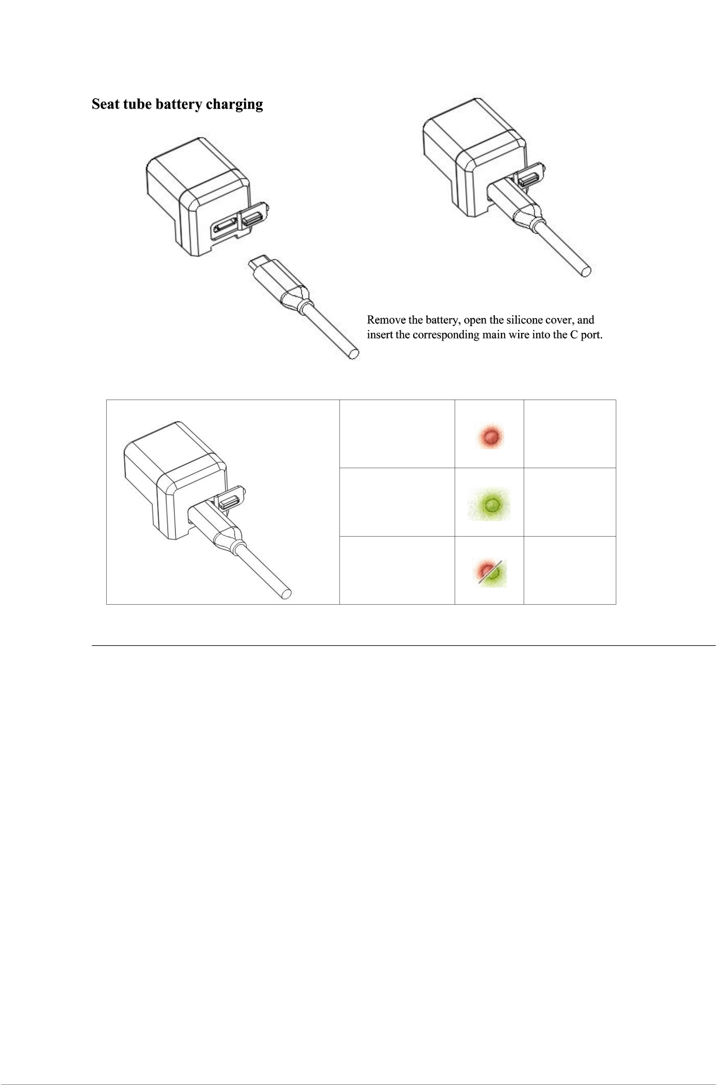
Note: All images in this manual are schematic diagrams; they may differ slightly from the
actual product
–
please refer to the actual product for accurate information.
Charging Base Indicator Light Instructions
Red indicator light
stays on
continuously
Battery
charging in
progress
Indication light
remains constantly
green.
charge
complete
The indicator light
flashes alternately
in red and green.
Charging故障
matters need attention
1. This product has an IP65 protection rating. Note: This rating applies only to the saddle
head (when the battery is properly installed) and the push-button controller; it does not
cover the tube body.
2. Operating temperature range: Discharging – –10°C to 50°C; Charging – 0°C to 45°C;
3. Do not immerse the battery in water or any other liquid;
4. The battery charging port should be kept dry. If the port is damp, please ensure it is
thoroughly dried before charging;
5. It is prohibited to disassemble, impact, or compress the battery of the base unit without
authorization, or to place it near a fire source or in any environment with high
temperatures;
6. If the battery exhibits any abnormal symptoms, such as significant swelling or bulging,
stop using it immediately;
7. Do not store the battery in high-temperature environments or near heat-generating
devices (e.g., direct sunlight, microwave ovens, ovens, etc.).
8. Do not store batteries in areas where infants or young children can reach them, to
prevent injury resulting from swallowing, chewing, or accidental handling;
9. Do not connect metal conductors to the battery terminals or touch the battery's ends;
10. Please dispose of batteries in accordance with local regulations; do not dispose of
batteries as general household waste.
11. For long-term storage, the battery should be charged every three months using the
charging base for 0.5–1 hour to maintain the battery pack at a charge level of 40%–60%.

Related certifications: CE, FCC Related
certifications: CE, FCC
Note: All images in this manual are schematic diagrams; they may differ slightly from the actual
product
–
please refer to the actual product for accurate information.
Product Warranty Information
I. Warranty Scope and Duration
Applicableregions:Chinesemainland,EuropeanUnion,UnitedStates
Effectivedate:Fromthedateofpurchase
The authorized distributor provides the following limited warranty for this product:
Note: This warranty is valid only for the original purchaser and is non-transferable.
Should you require any after-sales service in accordance with this
warranty, please contact the retailer who sold you the electronic seat post
product or an authorized service center.
The product must be returned, and the original purchase receipt must be
provided. All warranty claim requests for electronically controlled seat tubes
shall be evaluated by the authorized service centers for such seat tubes. If
Where the authorized dealer has agreed to the warranty and after-sales service
terms, the authorized dealer may independently decide whether to repair,
replace, or refund the product. Within the limits permitted by local law, any
claim arising under this warranty must be filed within the warranty period and
within one year from the date on which such claim arises.
put forward.
II. Non-Warranty Regulations
1. Unauthorized repair, misuse, impact, negligence, abuse, introduction of foreign substances,
accident, modification, incorrect use of components not supplied with this product, or tearing
or altering labels or anti-counterfeiting markings;
2. The warranty period has expired;
3. Damage caused by force majeure;
4. Cases where the product does not exhibit any performance-related faults as
listed in the Product Fault List;
5. When performance failures listed in the "Product Failure List" arise in
the product or its accessories due to human error.
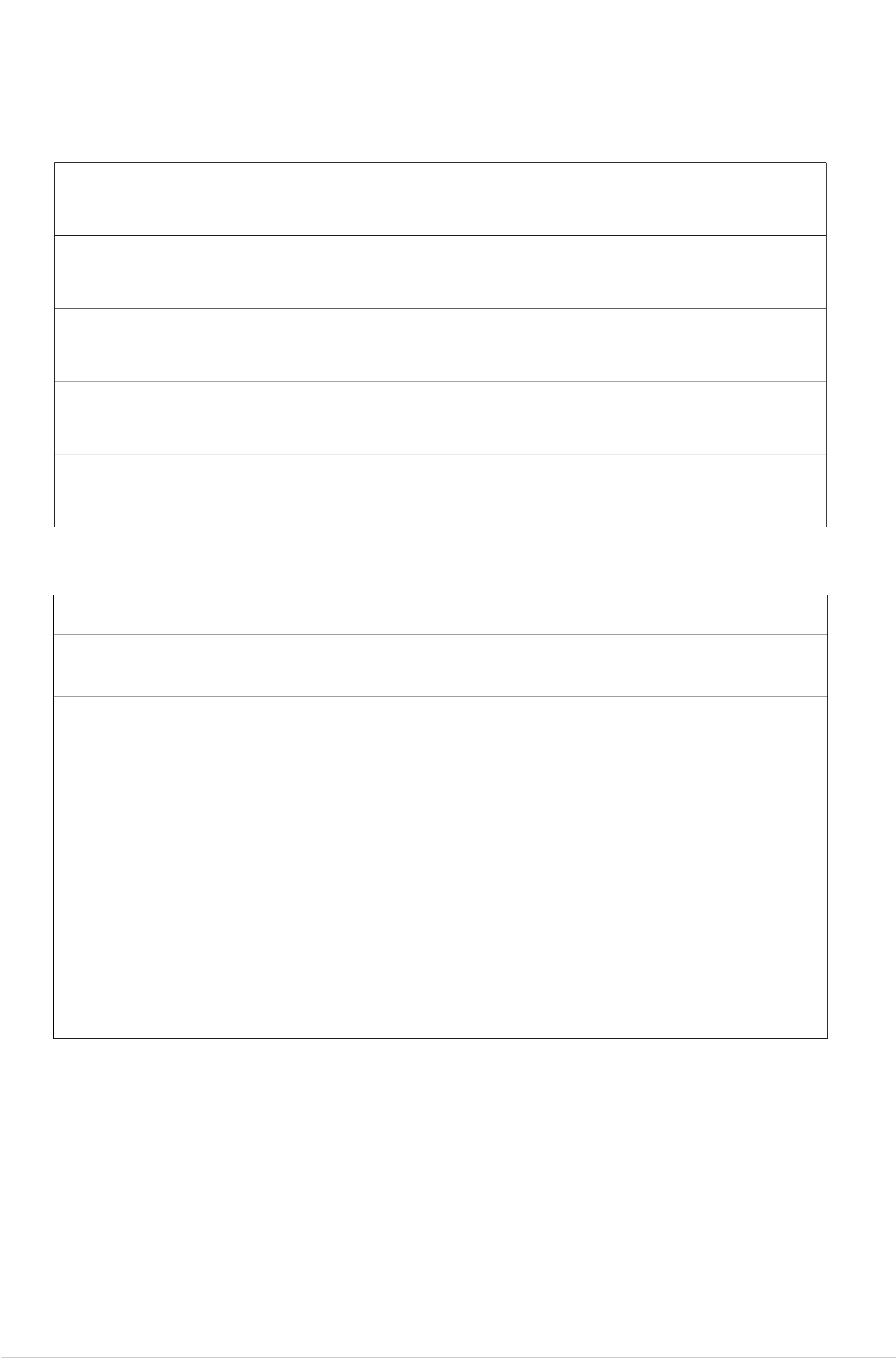
component
Warranty Period
Seat Pipe
12 months
cell
12 months
controller
12 months
Note: All images in this manual are schematic diagrams; they may differ slightly from
the actual product – please refer to the actual product for accurate information.
III. Product Malfunction
compo
nent
hitch
Seat
Pipe
Material defects, fracture, deformation
The seat tube cannot be adjusted for upward or downward
travel.
Electrical system not operating
Battery/Char
ging Base
runner block
controller
Not working
Note: To ensure the safe transportation of your products, it is recommended that you retain the packaging
box for at least 30 days from the date of receipt.
maintenance period
Maintenance Content
After each ride
Wipe away dust or sand from the telescopic
section of the seat tube using a damp cloth.
Annual; every 500 hours of riding; or
every 10,000 rides
Replace lubricant
Every two years / After 1,000 hours
of riding / After 20,000 rides
We recommend sending the
product to an authorized after-
sales service center for
comprehensive disassembly and
maintenance, including the
replacement of all wear parts.
Reminder: For those participating in downhill hiking (DH), park cycling, or extreme free riding, or when
riding in extremely wet/muddy or dry conditions...
For riders operating their bikes in dusty environments, it is recommended to perform maintenance
earlier than the above-mentioned schedule, as needed. If you hear, see, or notice any abnormality,
please stop riding immediately and contact an authorized service center for proper repair.