&
Assembly Instructions
OWNER’S MANUAL
v. S2CCO-102418
S2CCO
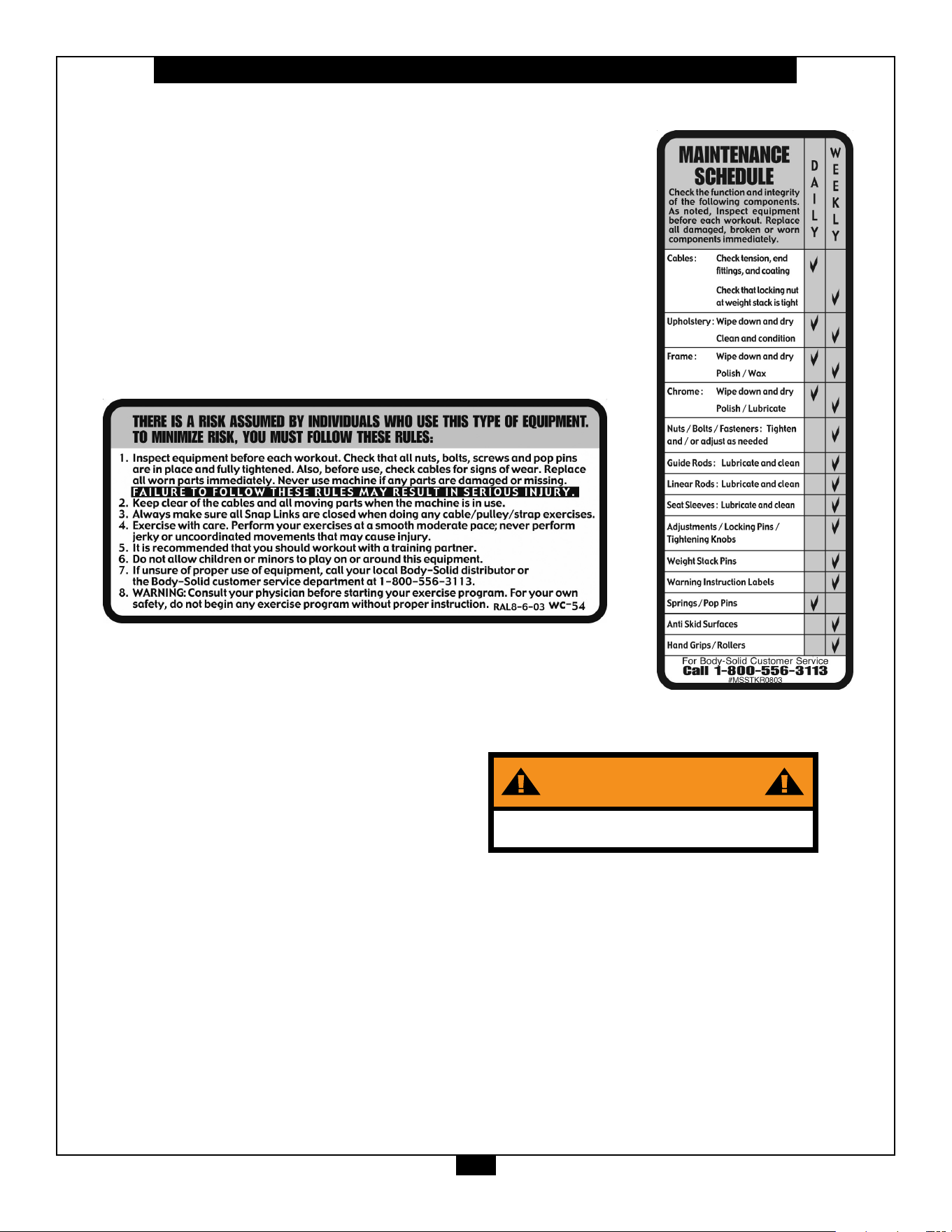
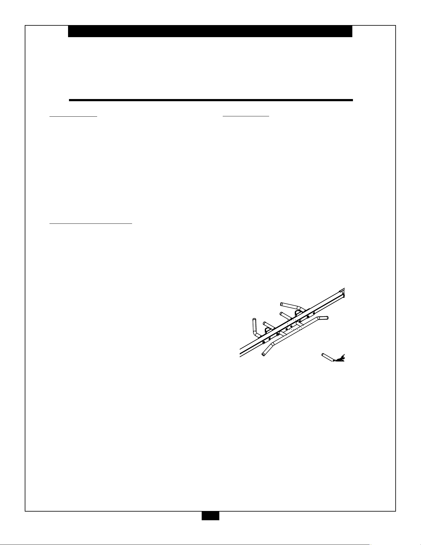
Warning, Safety & Maintenance
2
Be sure that all users carefully read and understand all
warning, safety and maintenance labels on the machine
before each use. Failure to do so may result in death or
serious injury.
It is imperative that you retain this Owner’s Manual and be
sure all warning labels are legible and intact. Replacement
Owner’s Manuals and warning labels are available from your
local Body-Solid dealer.
If you have any questions about the operation, set up or
maintenance of this machine please call our customer service
department at 1 (800) 556-3113.
Warning, Safety & Maintenance
Be sure that all users carefully read and understand all
warning, safety and maintenance labels on the machine
before each use. Failure to do so may result in serious injury.
It is imperative that you retain this Owner’s Manual and be
sure all warning labels are legible and intact. Replacement
Owner’s Manuals and labels are available from your local
Body-Solid dealer. If you have any questions about the
operation, set up or maintenance of this machine please call
our customer service department at 1 (800) 556-3113.
#DWRULE-4
Warning Label for Rules
#DWSM-5
Warning Label for Maintenance
Although Body-Solid provides the highest quality of materials and
workmanship in its products, the fact remains that component parts eventually wear
out over time and with use. This is particularly true with reference to pliable
moving parts such as cables. In spite of any expressed and/or implied warranties,
intervening factors such as improper use, unusually heavy use, improper installation,
improper alignment, poor maintenance, etc. serve to drastically reduce the usable
life and safety of cables.
Be advised that dangerous conditions can arise even during warranty
periods and that any expressed and/or implied warranties Do Not Negate the
owner’s responsibility to thoroughly, carefully and daily inspect all cables on this
machine.
Serious injury can occur if you are struck by falling weights or moving parts.
The risk that you assume by using this type of equipment can be reduced by
following a few simple steps:
Cable inspection should be performed daily. Inspect all cables, the
nylon coating on all cables and the area near the fittings at each end of each cable.
Replace any damaged or worn cables immediately. Do not allow the machine to
be used until damaged or worn cables are replaced.
Important: Cables are wear items. It is your responsibility to prevent
unexpected breakage. The actual wire strands, the fittings and the nylon coating
itself must all be scrutinized. Using or allowing a machine to be used with a suspect
cable can result in serious injury.
The nylon coating on a cable is essential for cable life and safety. Visually
inspect all cables and pulleys. Look at the cables as they travel around the cams
and pulleys. A cable that is wearing may exhibit a “ballooned” or broken coating in
the area that passes over the pulley. Damage to the coating is an early warning
signal. A cable should be replaced if the nylon coating is missing, is damaged in
anyway, has pulled or shrunk from the fittings at the end of the cables, or if it is
discolored. Discoloration of the cable coating is an early indication of internal
problems such as wear or fraying.
Annual cable replacement (semiannual in multi-user settings) is strongly
recommended as an additional precaution. The rate at which cables wear depends
on many factors including: number of users, number of repetitions, weight setting,
misuse, abuse, etc. Because of this, periodic cable replacement is not a sufficient
safeguard against unexpected breakage.
Nothing short of a thorough, careful, daily inspection constitutes an
adequate safety program.
Warning
Safety and Maintenance of Cables
WARNING
Bolt machine to the ground before use

Table of Contents
3
• SAFETY INSTRUCTIONS.............................. PAGE 4
• PREPARATION............................................... PAGE 5
• HARDWARE LIST........................................... PAGE 6
• HARDWARE ILLUSTRATION......................... PAGE 8
• PART / LIST ILLUSTRATION......................... PAGE 14
• ASSEMBLY INSTRUCTIONS........................ PAGE 24
• EXPLODED VIEW......................................... PAGE 48
• CONTACT PAGE........................................... PAGE 52

Important Safety Instructions
4
Beforebeginninganytnessprogram,youshouldobtainacompletephysicalexaminationfromyourphysician.
Il est conseille de subir un examen medical complet avant d’entreprendre tout programme d’exercise.
Si vous avez des etourdissements ou des faiblesses, arretez les exercices immediatement.
Antes de comenzar cualquier programma de ejercicios, deberias tener un examen sico con su doctor.
When using exercise equipment, you
should always take basic precautions,
including the following:
m ReadallinstructionsbeforeusingtheS2CCO.
Theseinstructionsarewrittentoensureyoursafety
andtoprotecttheunit.
m Do not remove any safety labels from the
machine.
m Donotallowchildrenonorneartheequipment.
m Usetheequipmentonlyforitsintendedpurpose
asdescribedinthisguide.Donotuseaccessory
attachmentsthatarenotrecommendedbythe
manufacturer.Suchattachmentsmightcause
injuries.
m Wearproperexerciseclothingandshoesforyour
workout,nolooseclothing.
m Keephands,limbs,looseclothing,andlonghairwell
outofthewayofallmovingparts.
m Usecarewhengettingonorotheunit.
m Donotoverexertyourselforworktoexhaustion.
m Ifyoufeelanypainorabnormalsymptoms,stop
yourworkoutimmediatelyandconsultyour
physician.
m Neveroperateunitwhenithasbeendroppedor
damaged.Returntheequipmenttoaservice
centerforexaminationandrepair.
m Neverdroporinsertobjectsintoanyopeningin
theequipment.
m Alwayschecktheunitanditscablesbeforeeach
use.Makesurethatallfastenersandcablesare
secureandingoodworkingcondition.
m Donotusetheequipmentoutdoorsornearwater.
Personal Safety During Assembly
m Beforebeginningassembly,pleasetakethetime
toreadtheinstructionsthoroughly.
m Readeachstepintheassemblyinstructionsand
followthestepsinsequence.Donotskipahead.
Ifyouskipahead,youmaylearnlaterthatyou
havetodisassemblecomponentsandthatyou
mayhavedamagedtheequipment.
m Assembleandoperatethe S2CCOonasolid,level
surface.Locatetheunitafewfeetfromthewalls
orfurnituretoprovideeasyaccess.
TheS2CCO isdesignedforyourenjoyment.Byfollowing
theseprecautionsandusingcommonsense,youwill
havemanysafeandpleasurablehoursof
healthfulexercisewithyourBody-Solid Pro Club
Cable Crossover Machine.
Afterassembly,youshouldcheckallfunctionsto
ensurecorrectoperation.Ifyouexperienceproblems,
rstrechecktheassemblyinstructionstolocateany
possibleerrorsmadeduringassembly.Ifyouareunable
tocorrecttheproblem,callthedealerfromwhomyou
purchasedthemachineorcall1-800-556-3113forthe
dealernearestyou.
Obtaining Service
PleaseusethisOwner’sManualtomakesurethatall
partshavebeenincludedinyourshipment.When
orderingparts,youmustusethepartnumberand
descriptionfromthisOwner’sManual.Useonly
Body-Solidreplacementpartswhenservicingthis
machine.Failuretodosowillvoidyourwarrantyand
couldresultinpersonalinjury.
Forinformationaboutproductoperationorservice,
checkouttheocialBody-Solidwebsiteat
www.bodysolid.comorcontactanauthorized
Body-SoliddealeroraBody-Solidfactory-authorized
servicecompanyorcontactBody-Solidcustomer
serviceatoneofthefollowing:
Toll Free: 1-800-556-3113
Phone: 1-708-427-3555
Fax: 1-708-427-3556
Hours: M-F 8:30-5:00 CST
E-Mail: [email protected]
Or write to: Body-Solid, Inc.
Service Department
1900 S. Des Plaines Ave.
Forest Park, IL 60130 USA
Retain this Owner’s Manual for future
reference. If you need to order replacement
parts please be prepared to provide the
following information when contacting us so
that we can assist you better.
1. Model Number
2. Place of Purchase
3. Serial Number (S/N)
4. Part # and Description
Preparation
5
Thankyouforpurchasingthe
S2CCO
.ThismachineispartoftheBody-Solidlineofqualitystrengthtraining
machines,whichletsyoutargetspecicmusclegroupstoachievebettermuscletoneandoverallbody
conditioning. To maximize your use of the equipment please study this Owner’sManual thoroughly.
Body-Solidcontinuallyseekswaystoimprovetheperformance,specicationsandproductmanualsinordertoensurethatonly
superiorproductsarereleasedfromourfactories.Pleasetakethetimetocarefullyreadthroughthismanualthoroughly.Instructions
containedinthisdocumentarenotintendedtocoveralldetailsorvariationspossiblewithBody-Solidequipment,ortocoverevery
contingencythatmaybemetinconjunctionwithinstallation,operation,maintenanceortroubleshootingoftheequipment.Even
thoughwehavepreparedthismanualwithextremecare,neitherthepublishernortheauthorcanacceptresponsibilityforanyerrors
in,oromissionfrom,theinformationgiven.Shouldadditionalinformationberequired,orshouldsituationsarisethatarenotcovered
bythismanual,themattershouldbedirectedtoyourlocalBody-Solidrepresentative,ortheServiceDepartmentatBody-SolidInc.
inForestPark,Illinois.
Required Tools
Thebasictoolsthatyoumustobtainbeforeassembling
theS2CCOincludebutarenotlimitedto:
m MetricAllenKeySet
m StandardAllenKeySet
m StandardWrenchSet
m MetricWrenchSet
m AdjustableWrench
m Screwdriver(standardand/orphillips)
Installation Requirements
Followtheseinstallationrequirementswhenassembling
theS2CCO:
SetuptheS2CCOonasolid,atsurface.Asmooth,at
surfaceunderthemachinehelpskeepitlevel.A
levelmachinehasfewermalfunctions.
Provideamplespacearoundthemachine.Open
spacearoundthemachineallowsforeasieraccess.
Insertallboltsinthesamedirection.Foraesthetic
purposes,insertallboltsinthesamedirectionunless
specied(intextorillustrations)todootherwise.
Leaveroomforadjustments.Tightenfastenerssuchas
bolts,nuts,andscrewssotheunitisstable,butleave
roomforadjustments.Donotfullytightenfasteners
untilinstructedintheassemblystepstodoso.
Fill out and mail the warranty card.
Assembly Tips
Readall“Notes”oneachpagebeforebeginningeach
step.
WhileyoumaybeabletoassembletheS2CCOusing
theillustrationsonly,importantsafetynotesandother
tipsareincludedinthetext.
Somepiecesmayhaveextraholesthatyouwillnotuse.
Useonlythoseholesindicatedintheinstructionsand
illustrations.
NOTE: Withsomanyassembledparts,proper
alignmentandadjustmentiscritical.While
tighteningthenutsandbolts,besuretoleave
roomforadjustments.
NOTE: Thebottlesthataremarked“Poison”isyour
touchuppaint.Keepawayfromchildren.
CAUTION: Obtainassistance!Ifyoufeellikeyoucan’t
assembletheS2CCObyyourselfthendo
notattempttodosoasthiscouldresultin
injury.Reviewtheinstallationrequirements
beforeproceedingwiththefollowingsteps.
YourS/N#can
befoundhere
↑

6
S2CCO Hardware List
Part# Size Description Quantity
1
2
3
4
5
6
7
8
9
10
11
12
13
14
15
16
17
18
M12X110mm
M12X105mm
M12X35mm
M10X100mm
M10X90mm
M10X55mm
M10X50mm
M10X30mm
M8X100mm
M8X25mm
M6X16mm
M8X8mm
3/8”X2.0”
10-32X1/8”
5/16”X1.25”
M10X25mm
M5X20mm
M10X105mm
HEX HEAD BOLT
HEX HEAD BOLT
HEX HEAD BOLT
HEX HEAD BOLT
HEX HEAD BOLT
HEX HEAD BOLT
HEX HEAD BOLT
HEX HEAD BOLT
HEX HEAD BOLT
BUTTON HEAD CAP SCREW
PHILLIPS HEAD SCREW
SET SCREW
SOCKET HEAD CAP SCREW
SET SCREW
SHOULDER BOLT
BUTTON HEAD CAP SCREW
BUTTON HEAD CAP SCREW
HEX HEAD BOLT
8 PCS.
8 PCS.
16 PCS.
4 PCS.
4 PCS.
2 PCS.
14 PCS.
24 PCS.
2 PCS.
8 PCS.
6 PCS.
8 PCS.
2 PCS.
40 PCS.
2 PCS.
2 PCS.
2 PCS.
16 PCS.

Part# Size Description Quantity
7
S2CCO Hardware List
40
41
42
43
44
45
46
50
51
52
53
54
55
56
M12
M10
M8
5/16”-18
1/2”
1/2”
M5
M12
M10
M8
M6
3/8”
M10
M5
NYLON LOCK NUT
NYLON LOCK NUT
NYLON LOCK NUT
NYLON LOCK NUT
FLANGE HEX NUT
HEX NUT
NYLON LOCK NUT
FLAT WASHER
FLAT WASHER
FLAT WASHER
FLAT WASHER
LOCK WASHER
LOCK WASHER
FLAT WASHER
32 PCS.
40 PCS.
10 PCS.
2 PCS.
4 PCS.
2 PCS.
2 PCS.
64 PCS.
108 PCS.
20 PCS.
6 PCS.
2 PCS.
2 PCS.
2 PCS.
45
8
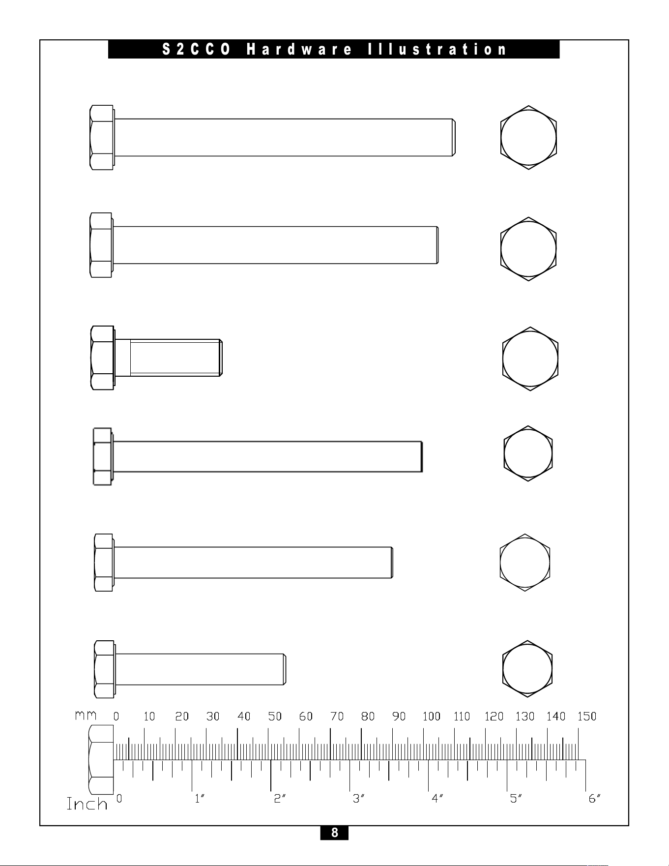
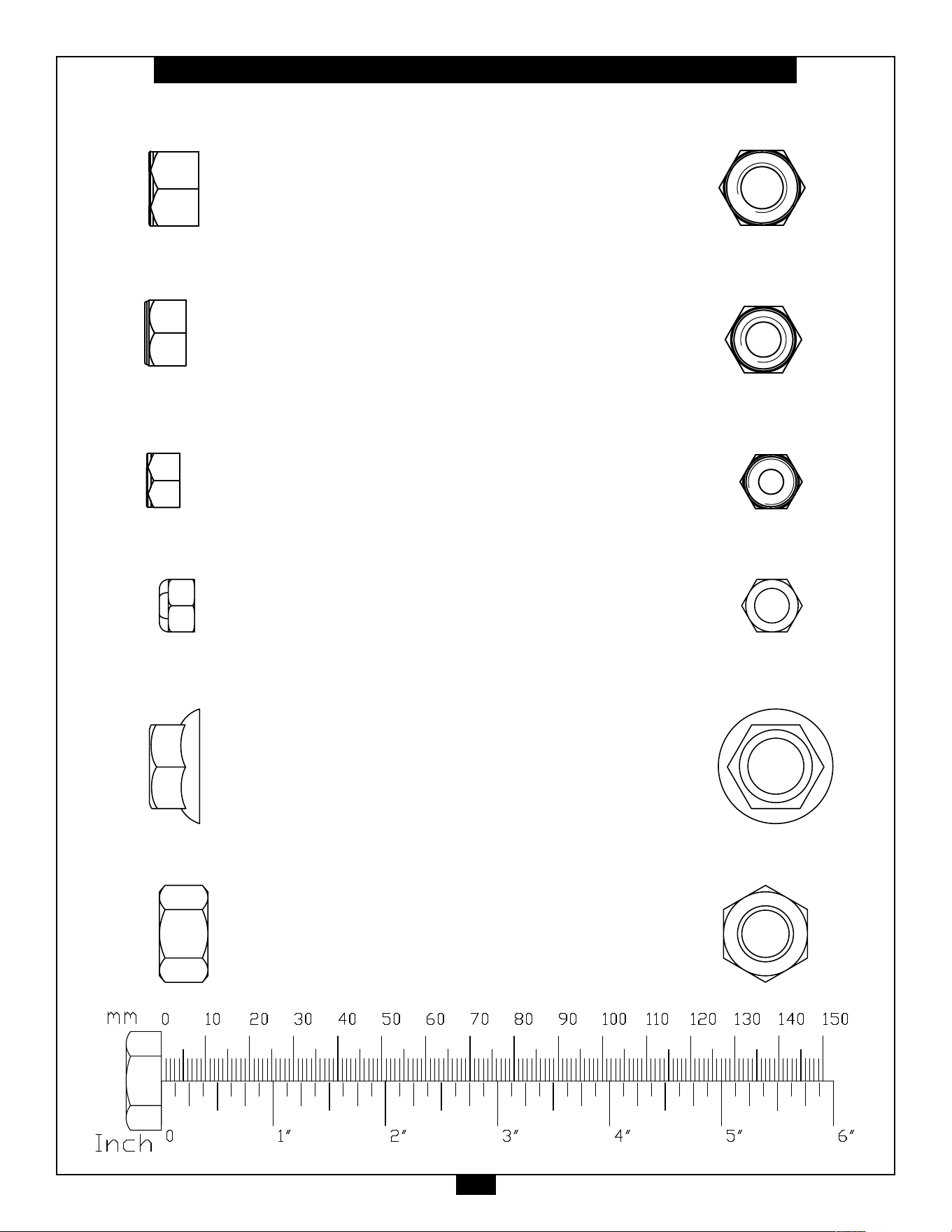
S2CCO Hardware Illustration
Part#1 HEX HEAD BOLTM12X110mm QTY.8
Part#2 HEXHEADBOLTM12X105mm QTY.8
Part#3 HEXHEADBOLTM12X35mm QTY.16
Part#4 HEXHEADBOLTM10X100mm QTY.4
Part#5 HEXHEADBOLTM10X90mm QTY.4
Part#6 HEXHEADBOLTM10X55mm QTY.2
PART #1 FLAT HEAD CAP SCREW M10X25 FULL THREAD-NL QTY.2
PART #3 HEX HEAD BOLT M10X100 PARTIAL THREAD QTY.1
PART #6 HEX HEAD BOLT M10X30 FULL THREAD QTY.3
PART #2 HEX HEAD BOLT M10X35 PARTIAL THREAD QTY.1
PART #4 HEX HEAD BOLT M10X50 PARTIAL THREAD QTY.8
PART #5 HEX HEAD BOLT M12X35 PARTIAL THREAD
QTY.8
PART #7 SOCKET HRAD CAP SCREW M8X20 FULL THREAD QTY.1
PART #8 ALLEN SCREW M4X8 FULL THREAD QTY.1
Part #1 HEX HEAD BOLT M10X105mm PARTIAL QTY. 4
Part #2 HEX HEAD BOLT M10X35mm PARTIAL QTY. 1
Part #3 HEX HEAD BOLT M10X45mm PARTIAL QTY. 2
Part #4 HEX HEAD BOLT M10X50mm PARTIAL QTY. 8
Part #5 HEX HEAD BOLT M10X65mm PARTIAL QTY. 3
Part #6 HEX HEAD BOLT M10X75mm PARTIAL QTY. 5
Part #7 HEX HEAD BOLT M10X80mm PARTIAL QTY. 2
PART #1 FLAT HEAD CAP SCREW M10X25 FULL THREAD-NL QTY.2
PART #3 HEX HEAD BOLT M10X100 PARTIAL THREAD QTY.1
PART #6 HEX HEAD BOLT M10X30 FULL THREAD QTY.3
PART #2 HEX HEAD BOLT M10X35 PARTIAL THREAD QTY.1
PART #4 HEX HEAD BOLT M10X50 PARTIAL THREAD QTY.8
PART #5 HEX HEAD BOLT M12X35 PARTIAL THREAD
QTY.8
PART #7 SOCKET HRAD CAP SCREW M8X20 FULL THREAD QTY.1
PART #8 ALLEN SCREW M4X8 FULL THREAD QTY.1
45
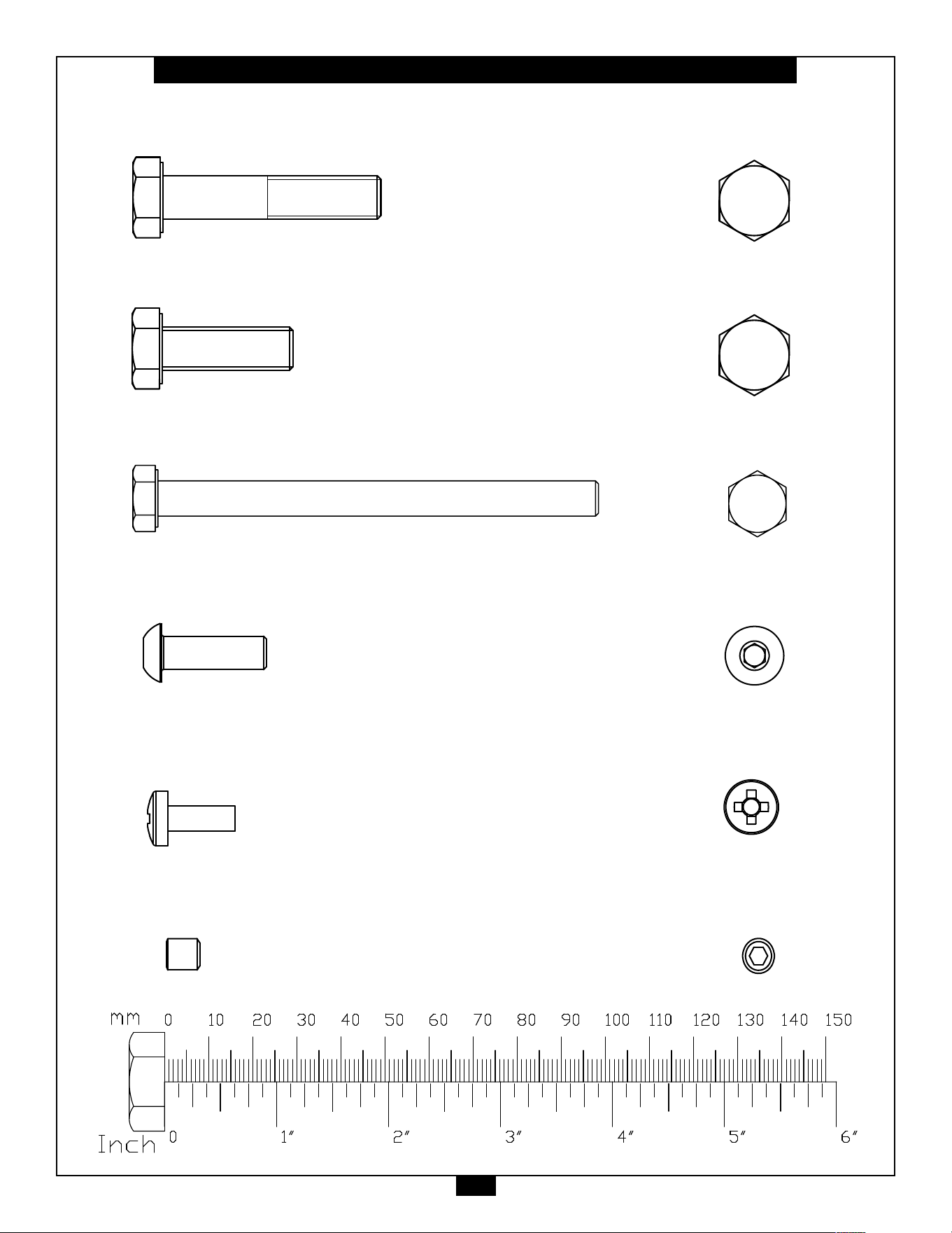
9
S2CCO Hardware Illustration
Part#7 HEXHEADBOLTM10X50mm QTY.14
Part#8 HEXHEADBOLTM10X30mm QTY.24
Part#9 HEXHEADBOLTM8X100mm QTY.2
Part#10 BUTTONHEADCAPSCREWM8X25mm QTY.8
Part#11 PHILLIPSHEADSCREWM6X16mm QTY.6
Part#12 SETSCREWM8X8mm QTY.8
PART #1 FLAT HEAD CAP SCREW M10X25 FULL THREAD-NL QTY.2
PART #3 HEX HEAD BOLT M10X100 PARTIAL THREAD QTY.1
PART #6 HEX HEAD BOLT M10X30 FULL THREAD QTY.3
PART #2 HEX HEAD BOLT M10X35 PARTIAL THREAD QTY.1
PART #4 HEX HEAD BOLT M10X50 PARTIAL THREAD QTY.8
PART #5 HEX HEAD BOLT M12X35 PARTIAL THREAD
QTY.8
PART #7 SOCKET HRAD CAP SCREW M8X20 FULL THREAD QTY.1
PART #8 ALLEN SCREW M4X8 FULL THREAD QTY.1
PART #10 PHILIP BOLT M6X16 FULL THREAD QTY.3
PART #13 BUTTON HEAD CAP SCREW M8X25 FULL THREAD QTY.4
PART #15 ALLEN SCREW 10-32*3.2 FULL THREAD QTY.8
PART #9 ALLEN SCREW M8X8 FULL THREAD QTY.4
QTY.2
PART #11 FLAT PHILIPS SCREW M5X16 FULL THREAD
PART #12 BUTTON HEAD CAP SCREW M6X40 FULL THREAD QTY.1
PART #14 SOCKET HRAD CAP SCREW 3/8”-16X50.8 FULL THREAD QTY.1
45
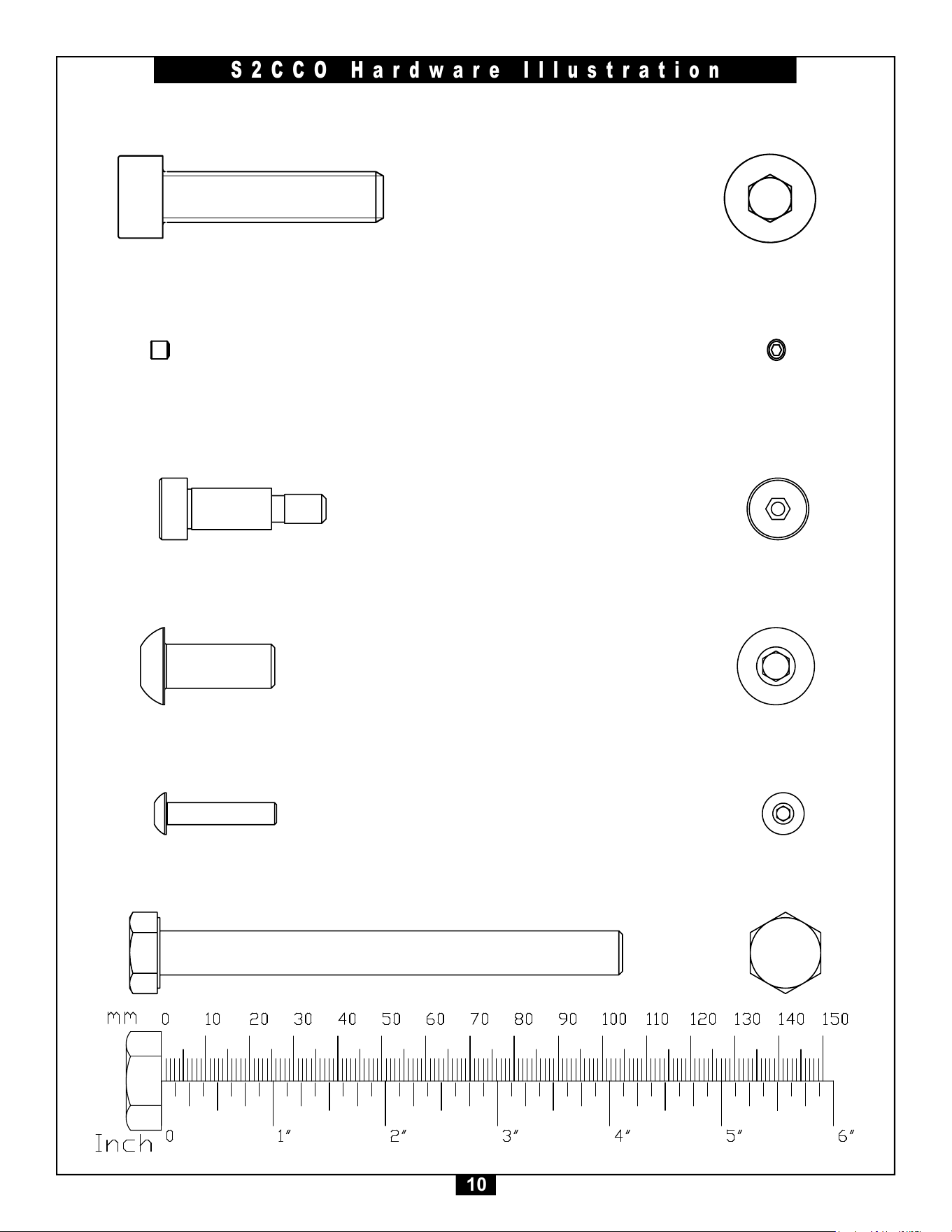
10
S2CCO Hardware Illustration
Part#13 SOCKET HEAD CAP SCREW3/8”X2.0” QTY.2
Part#14 SETSCREW10-32X1/8” QTY.40
Part#15 SHOULDERBOLT5/16”X1.25” QTY.2
PART #10 PHILIP BOLT M6X16 FULL THREAD QTY.3
PART #13 BUTTON HEAD CAP SCREW M8X25 FULL THREAD QTY.4
PART #15 ALLEN SCREW 10-32*3.2 FULL THREAD QTY.8
PART #9 ALLEN SCREW M8X8 FULL THREAD QTY.4
QTY.2
PART #11 FLAT PHILIPS SCREW M5X16 FULL THREAD
PART #12 BUTTON HEAD CAP SCREW M6X40 FULL THREAD QTY.1
PART #14 SOCKET HRAD CAP SCREW 3/8”-16X50.8 FULL THREAD QTY.1
Part#16 BUTTON HEAD CAP SCREWM10X25mm QTY.2
Part#17 BUTTON HEAD CAP SCREWM5X20mm QTY.2
Part#18 HEX HEAD BOLTM10X105mm QTY.16
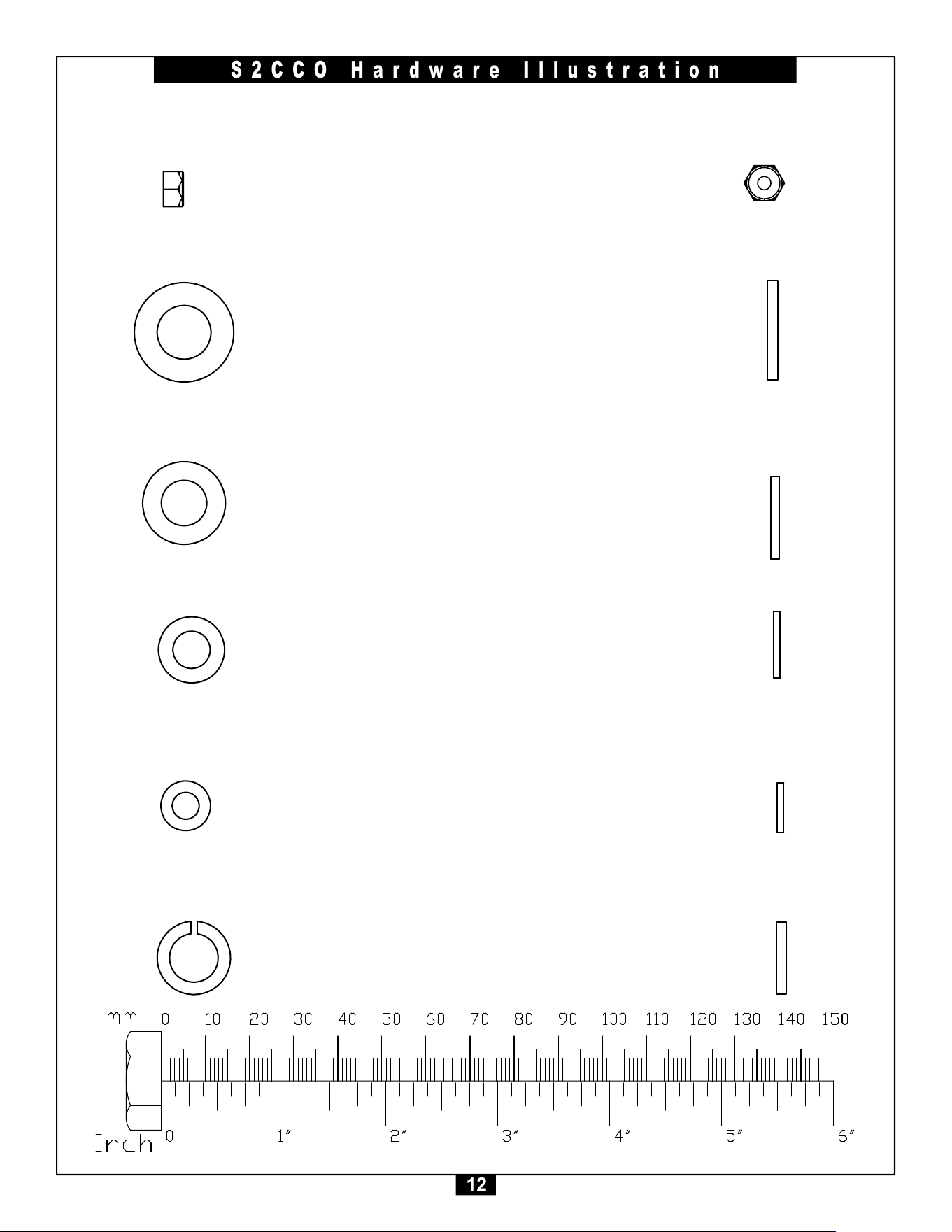
11
S2CCO Hardware Illustration
Part#40 NYLON LOCK NUT M12 QTY.32
Part#41 NYLON LOCK NUT M10 QTY.40
Part#42 NYLON LOCK NUT M8 QTY.10
45
PART #41 NYLON LOCK NUT M10 QTY.8
PART #42 NYLON LOCK NUT M12 QTY.8
PART #44 NYLON LOCK NUT M8 QTY.4
PART #45 HEX NUT 1/2"-13X11 QTY.1
PART #43 NYLON LOCK NUT M6 QTY.1
PART #40 FLANGE NUT M16 QTY.1
PART #41 NYLON LOCK NUT M10 QTY.8
PART #42 NYLON LOCK NUT M12 QTY.8
PART #44 NYLON LOCK NUT M8 QTY.4
PART #45 HEX NUT 1/2"-13X11 QTY.1
PART #43 NYLON LOCK NUT M6 QTY.1
PART #40 FLANGE NUT M16 QTY.1
PART #41 NYLON LOCK NUT M10 QTY.8
PART #42 NYLON LOCK NUT M12 QTY.8
PART #44 NYLON LOCK NUT M8 QTY.4
PART #45 HEX NUT 1/2"-13X11 QTY.1
PART #43 NYLON LOCK NUT M6 QTY.1
PART #40 FLANGE NUT M16 QTY.1
PART #41 NYLON LOCK NUT M10 QTY.8
PART #42 NYLON LOCK NUT M12 QTY.8
PART #44 NYLON LOCK NUT M8 QTY.4
PART #45 HEX NUT 1/2"-13X11 QTY.1
PART #43 NYLON LOCK NUT M6 QTY.1
PART #40 FLANGE NUT M16 QTY.1
PART #41 NYLON LOCK NUT M10 QTY.8
PART #42 NYLON LOCK NUT M12 QTY.8
PART #44 NYLON LOCK NUT M8 QTY.4
PART #45 HEX NUT 1/2"-13X11 QTY.1
PART #43 NYLON LOCK NUT M6 QTY.1
PART #40 FLANGE NUT M16 QTY.1
PART #41 NYLON LOCK NUT M10 QTY.8
PART #42 NYLON LOCK NUT M12 QTY.8
PART #44 NYLON LOCK NUT M8 QTY.4
PART #45 HEX NUT 1/2"-13X11 QTY.1
PART #43 NYLON LOCK NUT M6 QTY.1
PART #40 FLANGE NUT M16 QTY.1
Part#43 NYLON LOCK NUT5/16” QTY.2
Part#45 HEXNUT1/2” QTY.2
Part#44 FLANGENUT1/2” QTY.4
45
12
S2CCO Hardware Illustration
Part#52 FLATWASHERM8 QTY.20
Part#53 FLATWASHERM6 QTY.6
Part#54 LOCKWASHER3/8” QTY.2
PART #51 FLAT WASHER ij11Xij20X2 QTY.19
PART #52 FLAT WASHER ij13Xij24X2.5 QTY.16
PART #53 FLAT WASHER ij6.6Xij12X1.6 QTY.3
PART #54 FLAT WASHER ij9Xij16X1.6 QTY.8
PART #56 SPRING WASHER 1/2" QTY.1
PART #50 SPRING WASHER ij10 QTY. 5
PART #55 SPRING WASHER 3/8"
QTY.1
PART #51 FLAT WASHER ij11Xij20X2 QTY.19
PART #52 FLAT WASHER ij13Xij24X2.5 QTY.16
PART #53 FLAT WASHER ij6.6Xij12X1.6 QTY.3
PART #54 FLAT WASHER ij9Xij16X1.6 QTY.8
PART #56 SPRING WASHER 1/2" QTY.1
PART #50 SPRING WASHER ij10 QTY. 5
PART #55 SPRING WASHER 3/8"
QTY.1
PART #51 FLAT WASHER ij11Xij20X2 QTY.19
PART #52 FLAT WASHER ij13Xij24X2.5 QTY.16
PART #53 FLAT WASHER ij6.6Xij12X1.6 QTY.3
PART #54 FLAT WASHER ij9Xij16X1.6 QTY.8
PART #56 SPRING WASHER 1/2" QTY.1
PART #50 SPRING WASHER ij10 QTY. 5
PART #55 SPRING WASHER 3/8"
QTY.1
PART #51 FLAT WASHER ij11Xij20X2 QTY.19
PART #52 FLAT WASHER ij13Xij24X2.5 QTY.16
PART #53 FLAT WASHER ij6.6Xij12X1.6 QTY.3
PART #54 FLAT WASHER ij9Xij16X1.6 QTY.8
PART #56 SPRING WASHER 1/2" QTY.1
PART #50 SPRING WASHER ij10 QTY. 5
PART #55 SPRING WASHER 3/8"
QTY.1
PART #51 FLAT WASHER ij11Xij20X2 QTY.19
PART #52 FLAT WASHER ij13Xij24X2.5 QTY.16
PART #53 FLAT WASHER ij6.6Xij12X1.6 QTY.3
PART #54 FLAT WASHER ij9Xij16X1.6 QTY.8
PART #56 SPRING WASHER 1/2" QTY.1
PART #50 SPRING WASHER ij10 QTY. 5
PART #55 SPRING WASHER 3/8"
QTY.1
PART #51 FLAT WASHER ij11Xij20X2 QTY.19
PART #52 FLAT WASHER ij13Xij24X2.5 QTY.16
PART #53 FLAT WASHER ij6.6Xij12X1.6 QTY.3
PART #54 FLAT WASHER ij9Xij16X1.6 QTY.8
PART #56 SPRING WASHER 1/2" QTY.1
PART #50 SPRING WASHER ij10 QTY. 5
PART #55 SPRING WASHER 3/8"
QTY.1
Part#50 FLAT WASHER M12 QTY.
Part#51 NYLON LOCK NUT M10 QTY.108
PART #51 FLAT WASHER ij11Xij20X2 QTY.19
PART #52 FLAT WASHER ij13Xij24X2.5 QTY.16
PART #53 FLAT WASHER ij6.6Xij12X1.6 QTY.3
PART #54 FLAT WASHER ij9Xij16X1.6 QTY.8
PART #56 SPRING WASHER 1/2" QTY.1
PART #50 SPRING WASHER ij10 QTY. 5
PART #55 SPRING WASHER 3/8"
QTY.1
PART #51 FLAT WASHER ij11Xij20X2 QTY.19
PART #52 FLAT WASHER ij13Xij24X2.5 QTY.16
PART #53 FLAT WASHER ij6.6Xij12X1.6 QTY.3
PART #54 FLAT WASHER ij9Xij16X1.6 QTY.8
PART #56 SPRING WASHER 1/2" QTY.1
PART #50 SPRING WASHER ij10 QTY. 5
PART #55 SPRING WASHER 3/8"
QTY.1
PART #51 FLAT WASHER ij11Xij20X2 QTY.19
PART #52 FLAT WASHER ij13Xij24X2.5 QTY.16
PART #53 FLAT WASHER ij6.6Xij12X1.6 QTY.3
PART #54 FLAT WASHER ij9Xij16X1.6 QTY.8
PART #56 SPRING WASHER 1/2" QTY.1
PART #50 SPRING WASHER ij10 QTY. 5
PART #55 SPRING WASHER 3/8"
QTY.1
PART #51 FLAT WASHER ij11Xij20X2 QTY.19
PART #52 FLAT WASHER ij13Xij24X2.5 QTY.16
PART #53 FLAT WASHER ij6.6Xij12X1.6 QTY.3
PART #54 FLAT WASHER ij9Xij16X1.6 QTY.8
PART #56 SPRING WASHER 1/2" QTY.1
PART #50 SPRING WASHER ij10 QTY. 5
PART #55 SPRING WASHER 3/8"
QTY.1
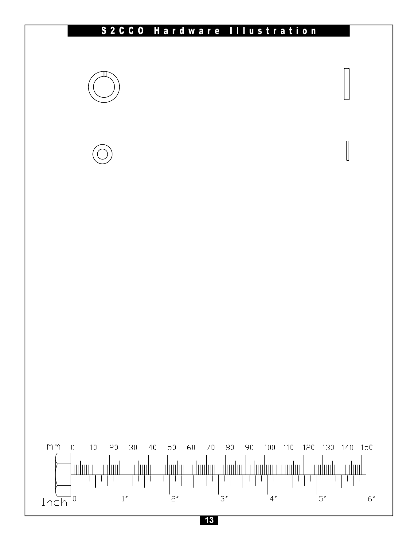
Part#46 NYLONLOCKNUTM5 QTY.2
45
13
S2CCO Hardware Illustration
Part#55 LOCK WASHER M10 QTY.2
Part#56 FLAT WASHER M5 QTY.2
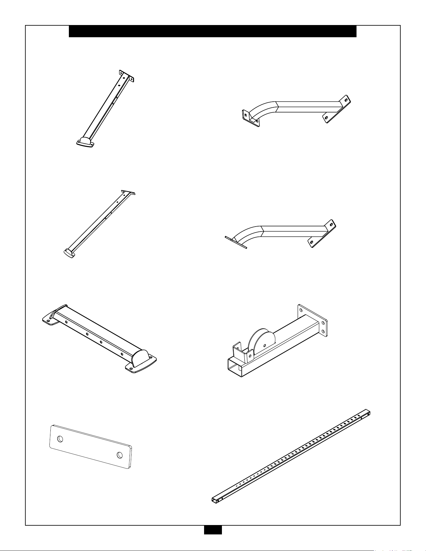
14
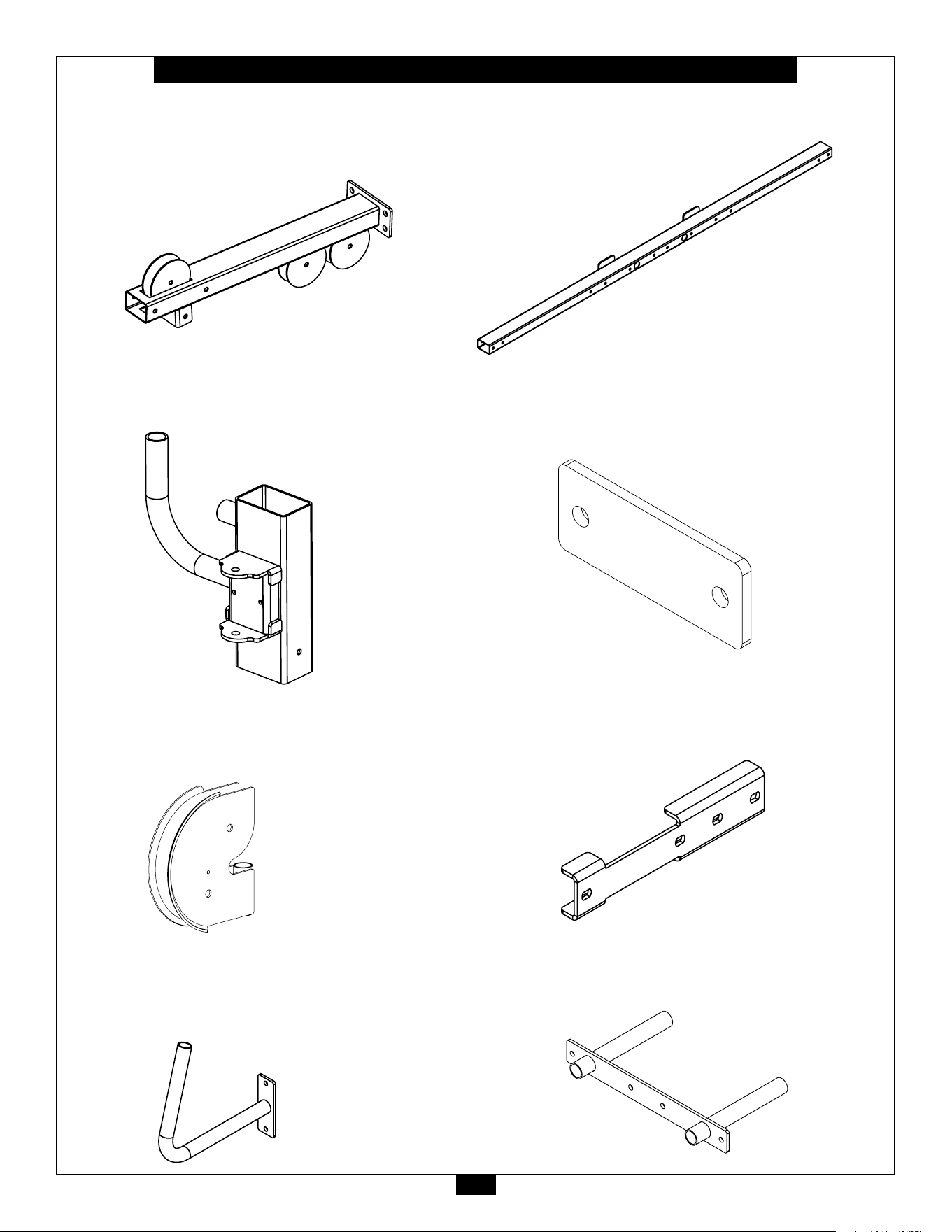
S2CCO Parts List/Illustration
PART A - LEFT BASE FRAME, 2PCS.
PART B - RIGHT BASE FRAME, 2PCS.
PART C - REAR BASE FRAME, 2PCS.
PART D - STEEL PLATE, 4PCS.
PART F - RIGHT BRACE , 2PCs.
PART G - LEFT BRACE, 2PCS.
PART H - FRONT BASE FRAME , 2PCS.
PART J - GUIDE POST, 1PC.
15
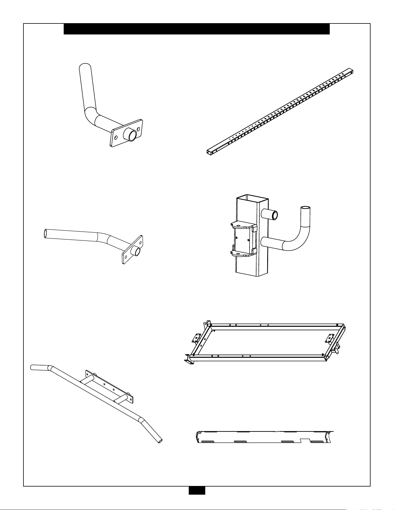
S2CCO Parts List/Illustration
PART K - TOP FRAME , 2PCS.
PART L - SWIVEL ADJUSTER , 1PC.
PART M - PULLEY HOLDER, 2PCS.
PART N - HANDLE, 2PCS.
PART P - CROSS MEMBER , 1PC.
PART Q - STEEL PLATE, 2PC.
PART R - BRACKET, 4PCS.
PART S - PULL UP BAR, 1PC.
16
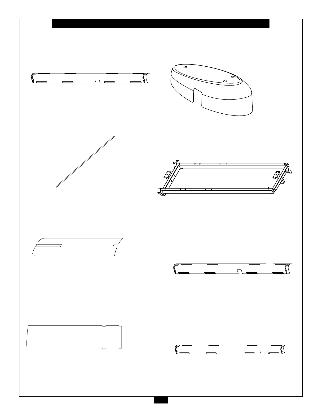
S2CCO Parts List/Illustration
PART T - RIGHT CHIN UP HANDLE, 1PC.
PART U - LEFT CHIN UP HANDLE, 1PC.
PART V - CENTER PUL UP BAR, 1PC.
PART WA - WEIGHT STACK FRAME, 1PC.
PART WB - SHORT SIDE SHROUD, 1PC.
PART X - GUIDE POST, 1PC.
PART W - SWIVEL ADJUSTER, 1PC.
17
S2CCO Parts List/Illustration
PART WD - CHROME GUIDE ROD, 4PCS.
PART WC - LONG SIDE SHROUD, 1PC.
PART WE - FRONT SHROUD, 1PC.
PART WF - REAR SHROUD, 1PCS.
PART WG - FRONT SHROUD, 1PCS.
PART WH - WEIGHT STACK FRAME, 1PC.
PART WJ - SHORT SIDE SHROUD, 1PC.
PART WK - LONG SIDE SHROUD, 1PC.
18
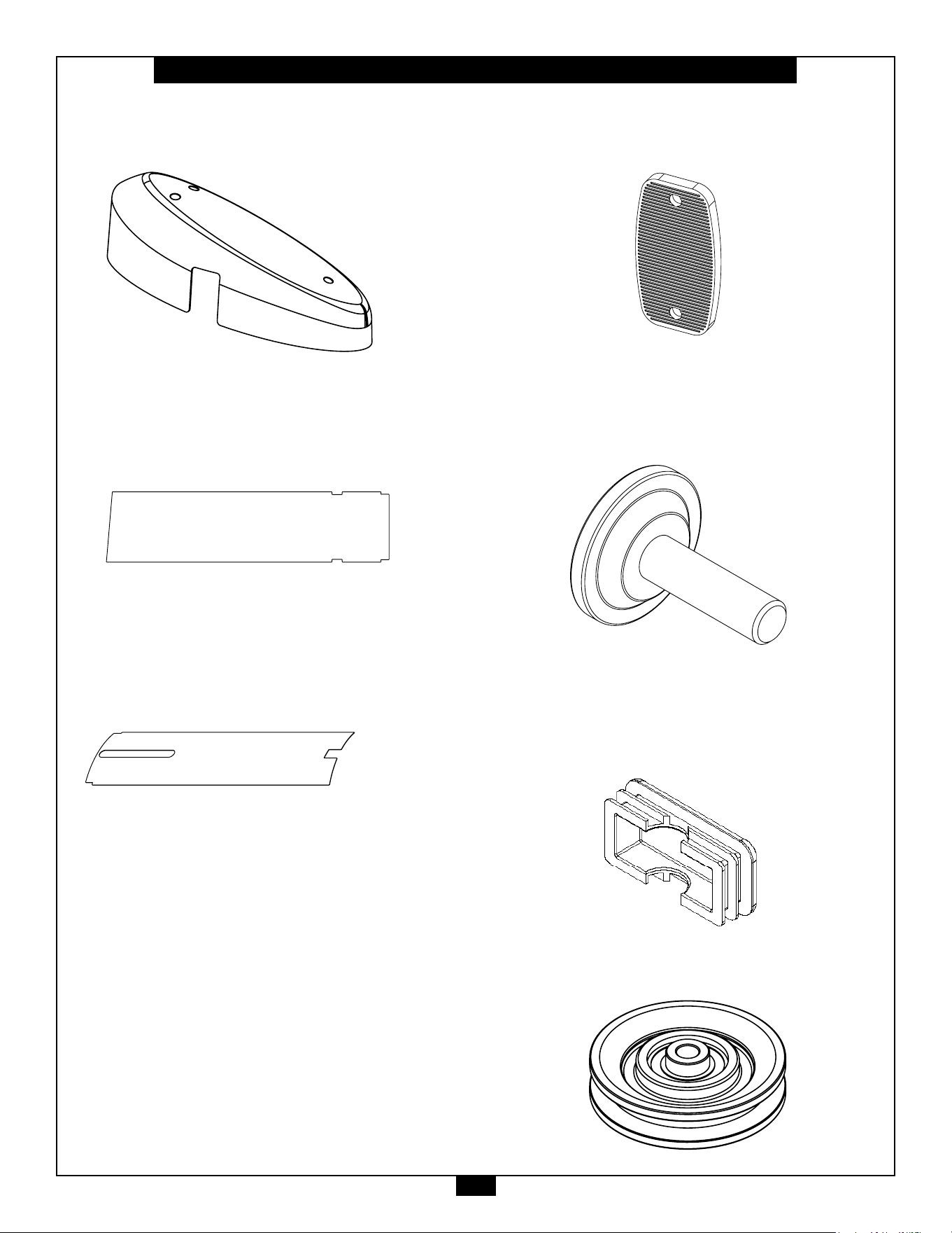
S2CCO Parts List/Illustration
PART WL - TOP SHROUD, 1PCS.
PART #60 - FOOT PAD, 8PCS.
PART #61 - ADJUSTABLE LEVELER,
2PCS.
PART #62 - PLASTIC END CAP, 4PC.
75x50mm
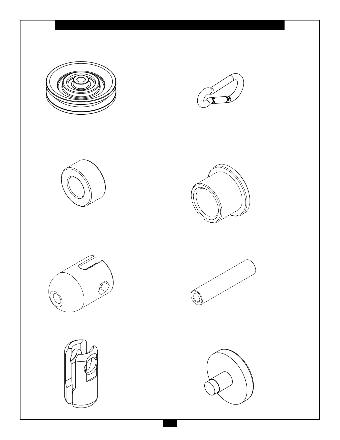
PART #63 - LARGE PULLEY, 8PCS.
PART WM - REAR SHROUD, 1PC.
PART WN - FRONT SHROUD, 1PC.
19
S2CCO Parts List/Illustration
PART #64 - SMALL PULLEY, 8PCS.
PART #65 - RUBBER SLEEVE, 4PCS.
PART #66 - CABLE BUMPBER, 2PCS.
PART #67 - CABLE CONNECTOR, 2PCS.
PART #68 - SNAP LINK, 2PCS.
PART #69 - BUSHING, 4PCS.
ø28xø22x18mm
PART #70 - STEEL TUBE, 2PCS.
ø16xø8.5x75mm
PART #71 - PLASTIC STOPPER, 4PCS.
20
S2CCO Parts List/Illustration
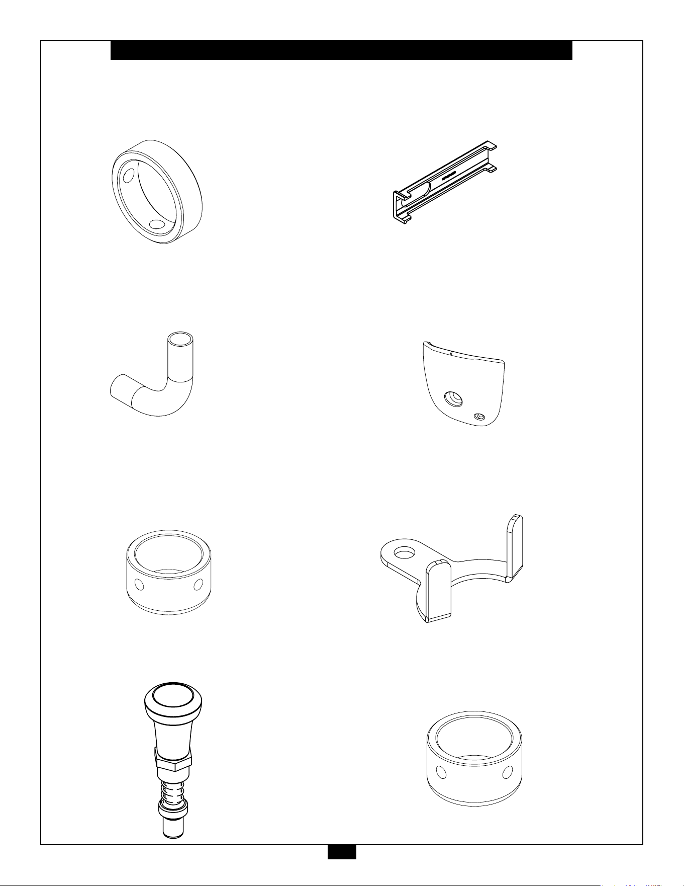
PART #72 - HANDLE END RING, 2PCS.
ø33xø26x9.5mm
PART #73 - HANDLE GRIP, 2PCS.
PART #74 - HANDLE END CAP, 2PCS.
ø33xø26x19mm
PART #75 - POP PIN, 2PCS.
PART #76 - PLASTIC BUSHING, 4PCS.
PART #77 - ROCK CLIMBING GRIP, 2PCS.
PART #78 - BRACKET, 2PCS.
PART #79 - HANDLE END CAP, 10PCS.
ø39.5xø32.5x19mm
21
S2CCO Parts List/Illustration
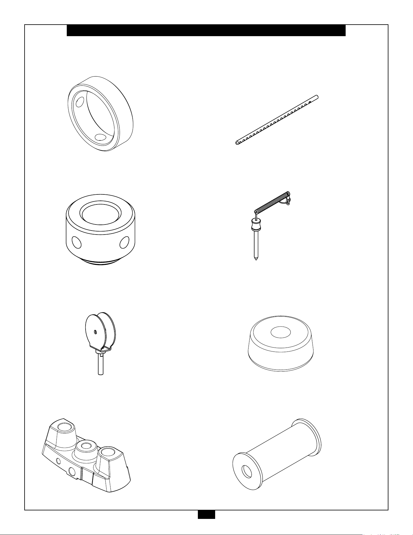
PART #80 - HANDLE END RING, 8PCS.
ø39.5xø32.5x9.5mm
PART #81 - SHAFT COLLAR, 4PCS.
PART #82 - SWIVEL PULLEY BRACKET,
2PCS.
PART #83 - TOP PLATE, 2PCS.
PART #84 - SELECTOR ROD, 2PCS.
PART #85 - SELECTOR PIN, 2PCS.
PART #86 - RUBBER DONUT, 4PCS.
PART #87 - WEIGHT RISER, 4PCS.
22
S2CCO Parts List/Illustration
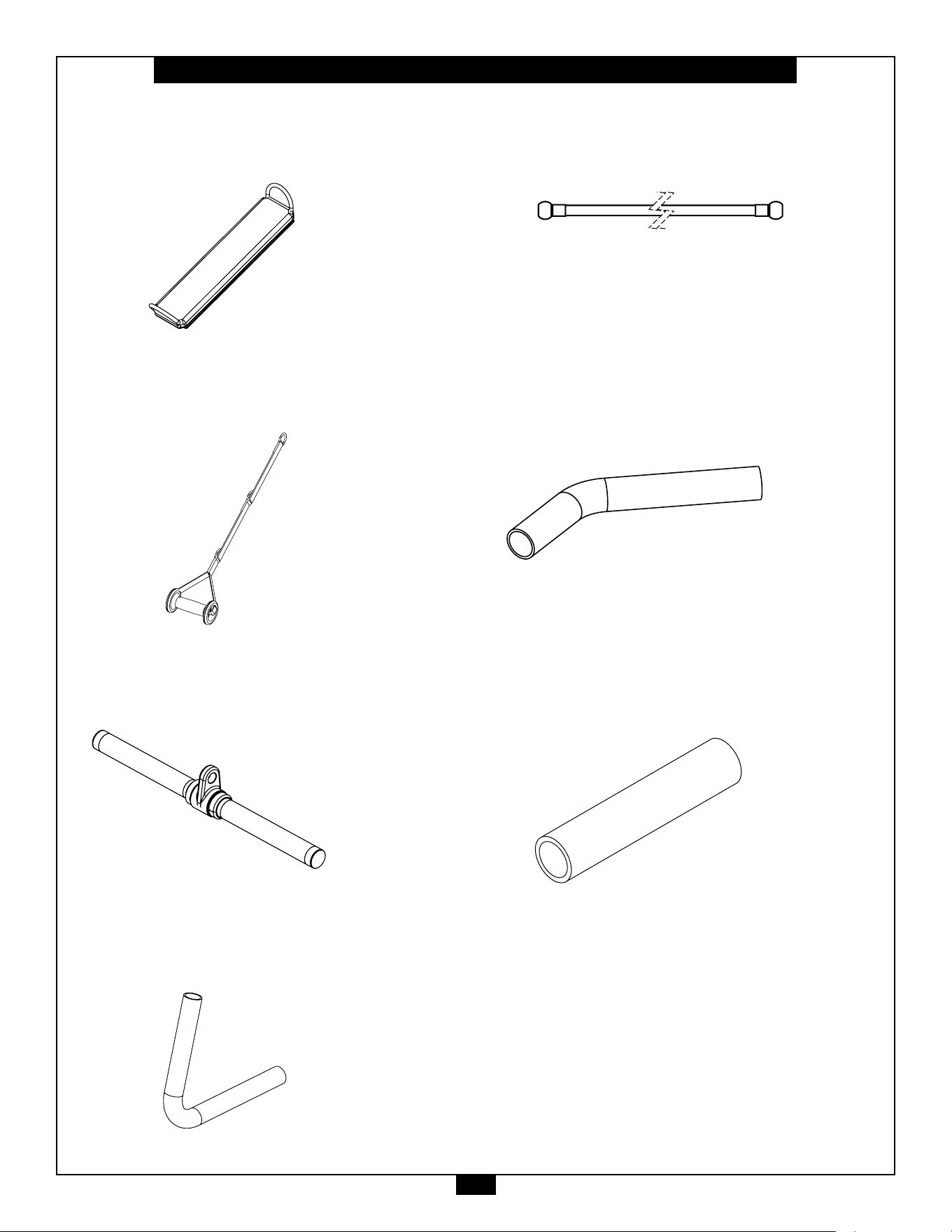
PART #93 - CHIN UP GRIP, 2PCS.
PART #89 - STRAP HANDLE, 2PC.
PART #94 - PULL UP GRIP, 2PCS
PART #91 - HANDLE GRIP, 4PCS.
PART #92 - CABLE, 2PC.
3$5738//(<63&6
3$57&$%/(3&6
3$57&$33&6
3$57+$1'/((1'&$33&6
3$57+$1'/(5,1*3&6
6$&3DUWV/LVW,OOXVWUDWLRQ
PP
3$57%86+,1*3&6
PART #88 - ANKLE CUFF, 1PCS.
PART #90 - LOW ROW BAR, 1PC

23
Note

24
STEP
1
Be careful to assemble all components
in the sequence they are presented.
NOTE:
Finger tighten all hardware in this step. DO NOT wrench tighten unless instructed.
Some components may be pre-assembled. Nylon lock nuts will not fully screw onto
bolts, they must be wrench tighten to fully go on.
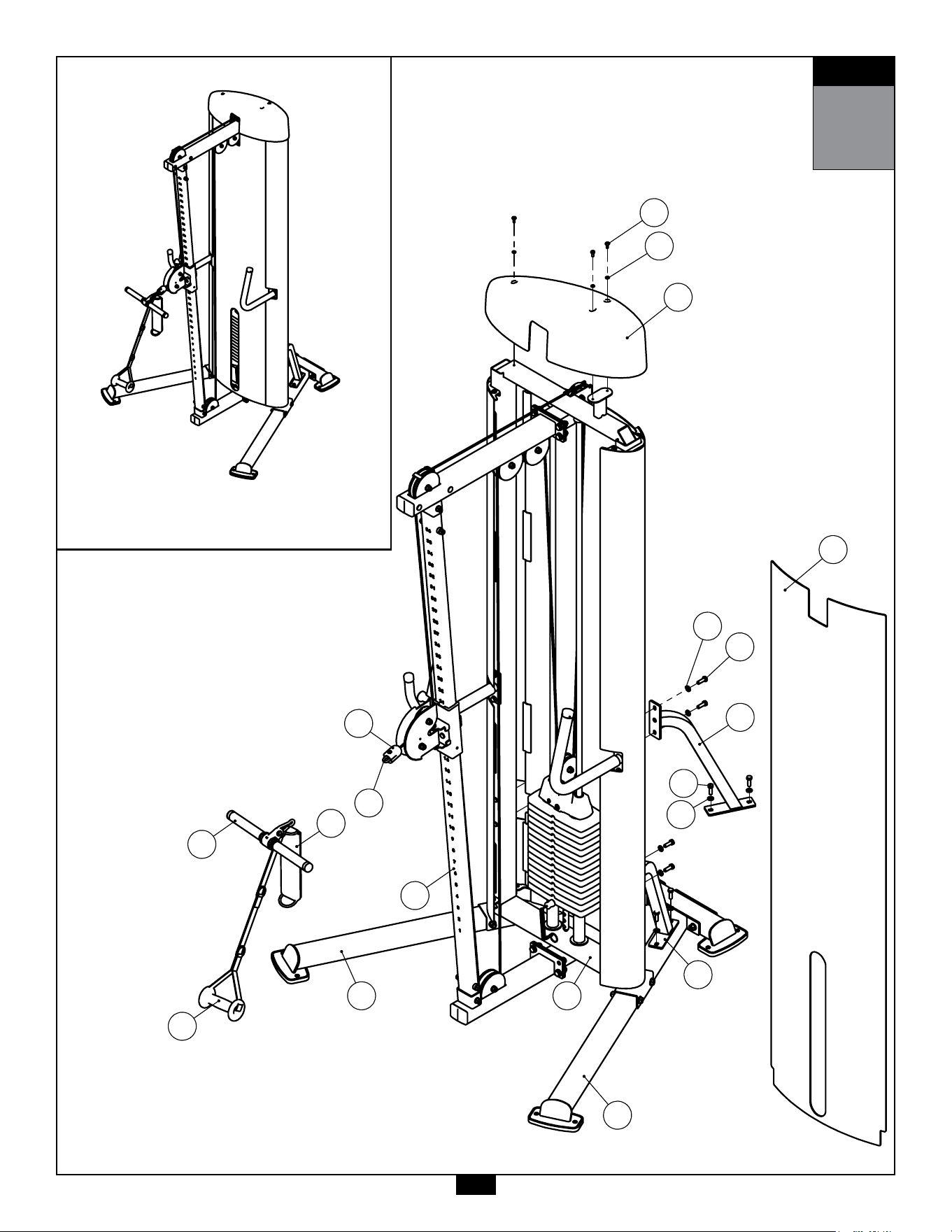
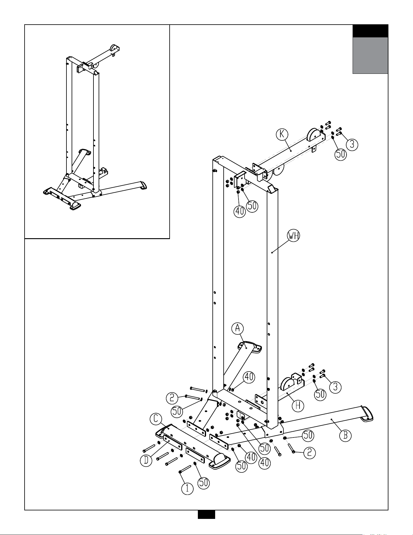
1A. AttachLeft&RightBaseFrames(A & B)toRearBaseFrame(C)using:
4 - (#1) M12X110mm Hex Head Bolt
8 - (#50) M12 Flat Washer
4 - (#40) M12 Nylon Lock Nut
2 - (D) Steel Plate
1B. AttachWeightStackFrame(WA)toLeft&RightBaseFrame(A & B)
using:
4 - (#2) M12X105mm Hex Head Bolt
8 - (#50) M12 Flat Washer
4 - (#40) M12 Nylon Lock Nut
1C. AttachFrontBaseFrame(H)toWeightStackFrame(WA)using:
4 - (#3) M12X35mm Hex Head Bolt
8 - (#50) M12 Flat Washer
4 - (#40) M12 Nylon Lock Nut
1D. AttachTopFrame(K)toWeightStackFrame(WA)using:
4 - (#3) M12X35mm Hex Head Bolt
8 - (#50) M12 Flat Washer
4 - (#40) M12 Nylon Lock Nut
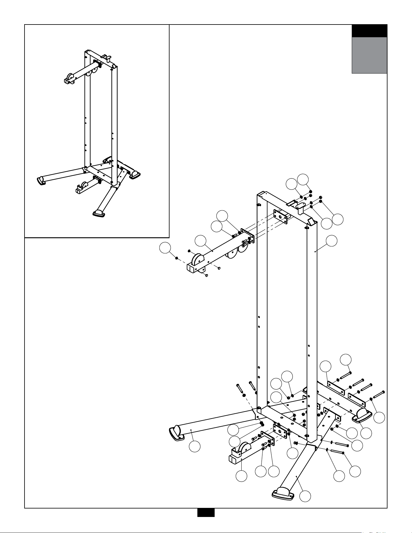
STEP
1
AboveshowsStep1assembledandcompleted.
25
K
77
H
A
B
2
50
3
50
WA
3 50
D
1
50
C
STEP
1
50
50
40
50
40
50
40
40
50
40
40
50
K
77
H
A
B
2
50
3
50
WA
3 50
D
1
50
C
STEP
1
50
50
40
50
40
50
40
40
50
40
40
50

26
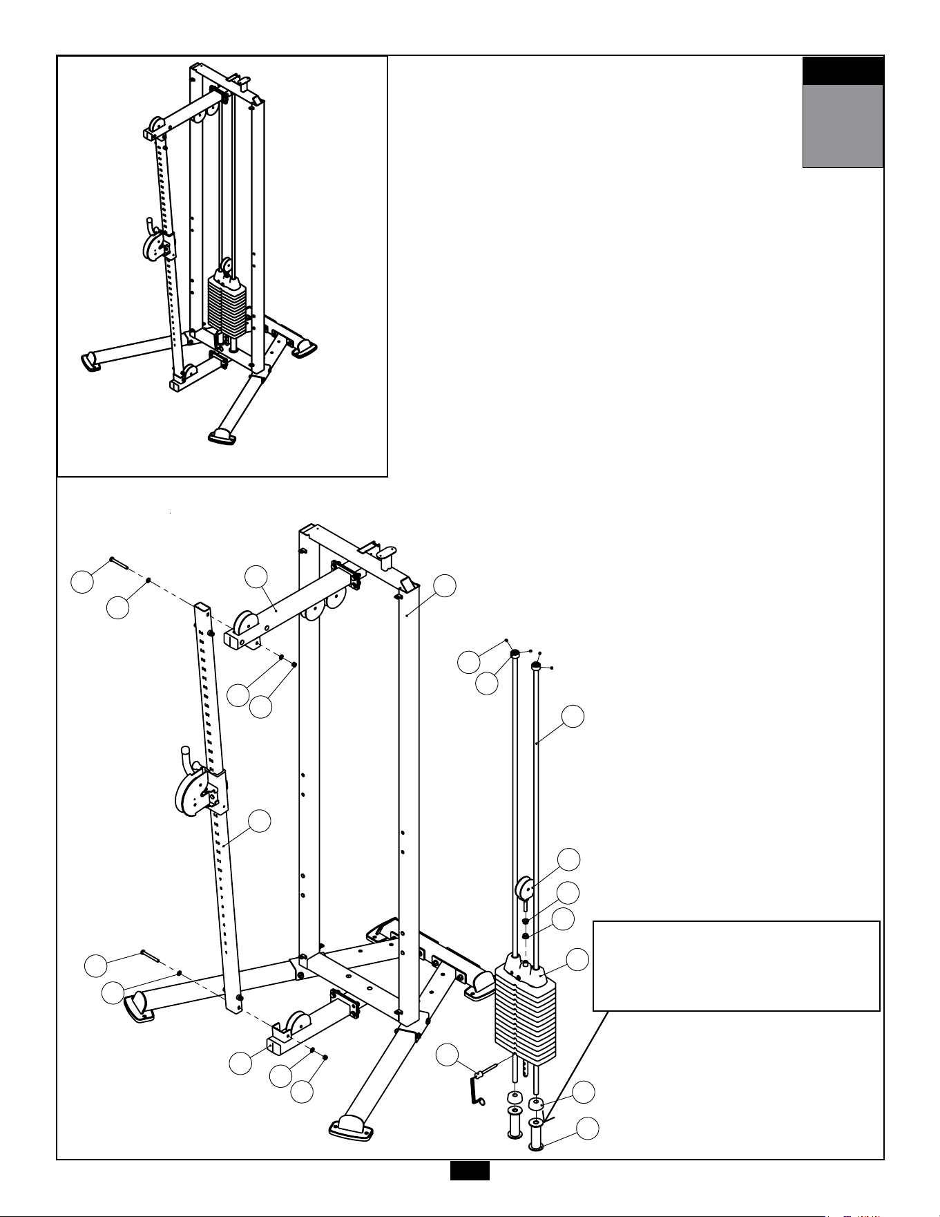
STEP
2
Be careful to assemble all components
in the sequence they are presented.
NOTE:
Finger tighten all hardware in this step. DO NOT wrench tighten unless instructed.
Some components may be pre-assembled. Nylon lock nuts will not fully screw onto
bolts, they must be wrench tighten to fully go on.
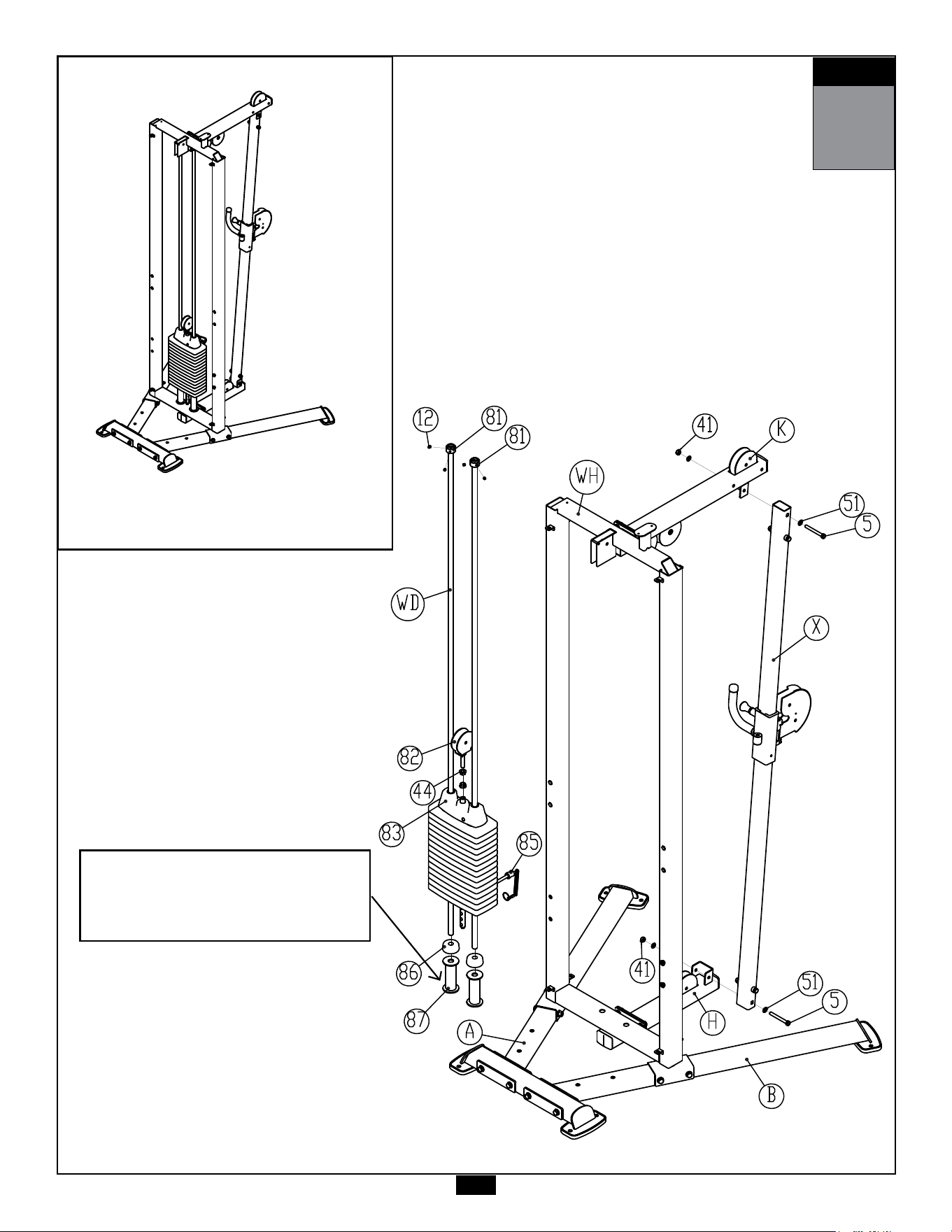
2A. AttachGuidPost(J)toTop&BaseFrame(H & K)using:
2 - (#5) M10x90mm Hex Head Bolt
4 - (#51) M10 Flat Washer
2 - (#41) M10 Nylon Lock Nut
2B. InstallChromeGuideRods(WD)intotheholesintheWeightStackFrame(WA).
2C. InstallWeightRisers(#87) & RubberDonuts(#67)andslidetothebottom
oftheGuideRods
Important Notes:
1. Install the rod ends with side holes into the bottom section of the Weight
Stack Frame.
2. If 20pcs of weight plates are to be installed, do not install Weight Risers (87)
2D. TiltGuideRods(WD) awayfromtheWeightStackFrame(WA) andinstall15pcs
ofweightplates.Becarefultoholdguiderodssteadilywheninstalling
weightplates.
2E. InstallTopPlate&SelectorRodAssembly(#83)ontotheGuideRods(WD) .
2F. InstallWeightStackPin(#85)usingthekeyringendthroughtheSwivelPully
Bracket(#82).
2G. InstallTwo1/2”FlangeHexNut(#44) &SwivelPulleyBracket(#82)ontotheGuide
Rods(WD) .
2H. InstallShaftCollars(#81)ontotheGuideRodssotheyaredirectlybelowtheguide
rodholesintheuppersectionoftheWeightStackFrame.
2J. SlideShaftCollars(#81)upwardsotheylocktheguiderodsinto
positionbytighteningthefourM8x8mmSetScrews(#12)
27
STEP
2
AboveshowsStep2assembledandcompleted.
STEP
2
5
51
51
41
5
51
51
41
85
87
86
83
WD
81
12
82
44
44
WA
K
H
J
STEP
2
5
51
51
41
5
51
51
41
85
87
86
83
WD
81
12
82
44
44
WA
K
H
J
Note:
Risers(#87)arenotnecessaryif
20pcsofweightplatesaretobe
installed

28
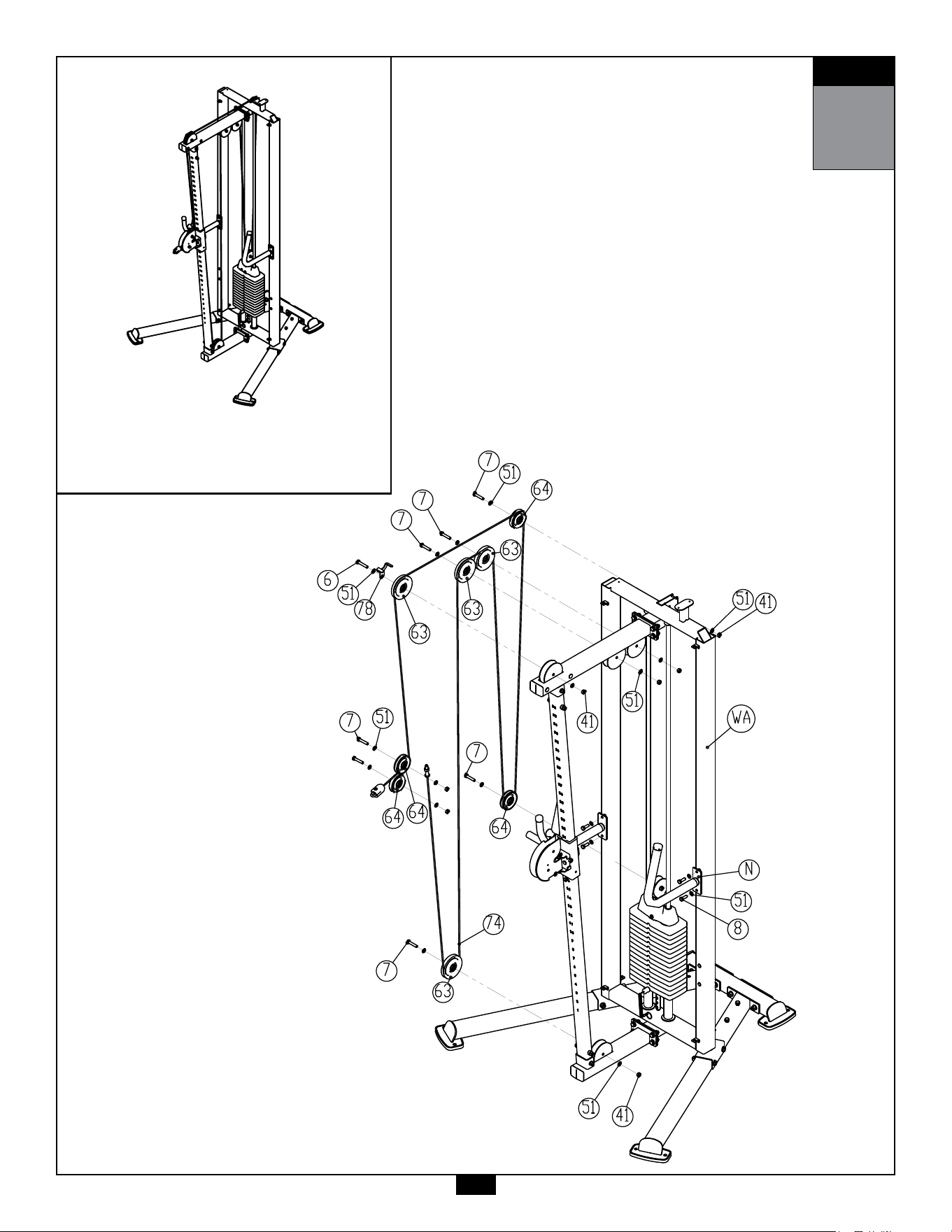
STEP
3
Be careful to assemble all components
in the sequence they are presented.
NOTE:
Finger tighten all hardware in this step. DO NOT wrench tighten unless instructed.
Some components may be pre-assembled. Nylon lock nuts will not fully screw onto
bolts, they must be wrench tighten to fully go on.
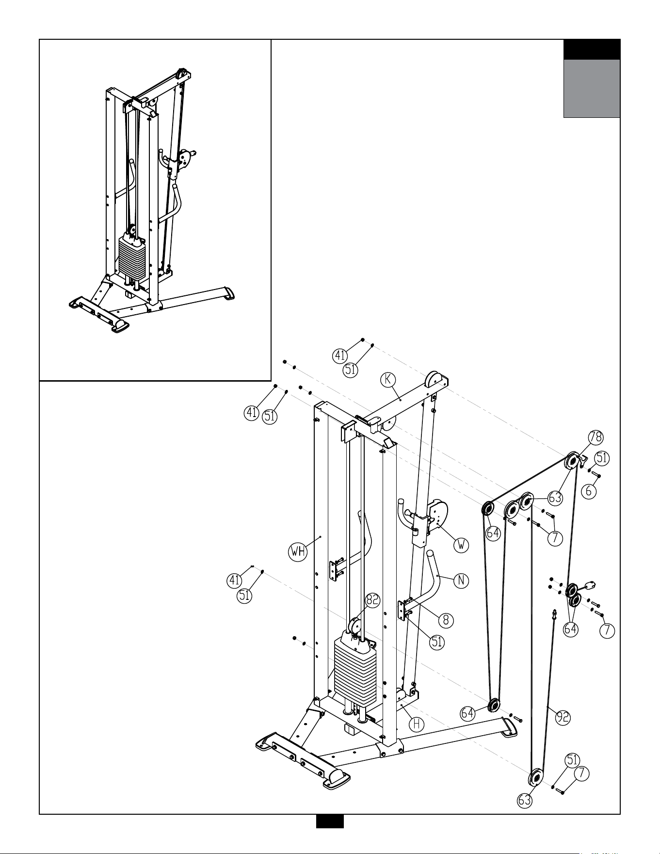
3A. InstallCable(#92)whileinstallingFourLargePulleys(#63)and
FourSmallPulleys(#64) intoFramesasshownin
Step3Drawingusing
1 - (#6) M10X55mm Hex Head Bolt
7 - (#7) M10X50mm Hex Head Bolt
16 - (#51) M10 Flat Washer
8 - (#41) M10 Nylon Lock Nut
1 - (#78) Bracket
3B. AttachTwoHandles(N)toWeightStackFrame(WA)using:
4 - (#8) M10X30mm Hex Head Bolt
4 - (#51) M10 Flat Washer
29
STEP
3
AboveshowsStep3assembledandcompleted.
7
51
64
6
51
78
63
64
64
7
51
63
64
8
51
N
41
51
51
41
7
7
63
63
41
51
7
7
WA
92
STEP
3

30
STEP
4
Be careful to assemble all components
in the sequence they are presented.
NOTE:
Finger tighten all hardware in this step. DO NOT wrench tighten unless instructed.
Some components may be pre-assembled. Nylon lock nuts will not fully screw onto
bolts, they must be wrench tighten to fully go on.
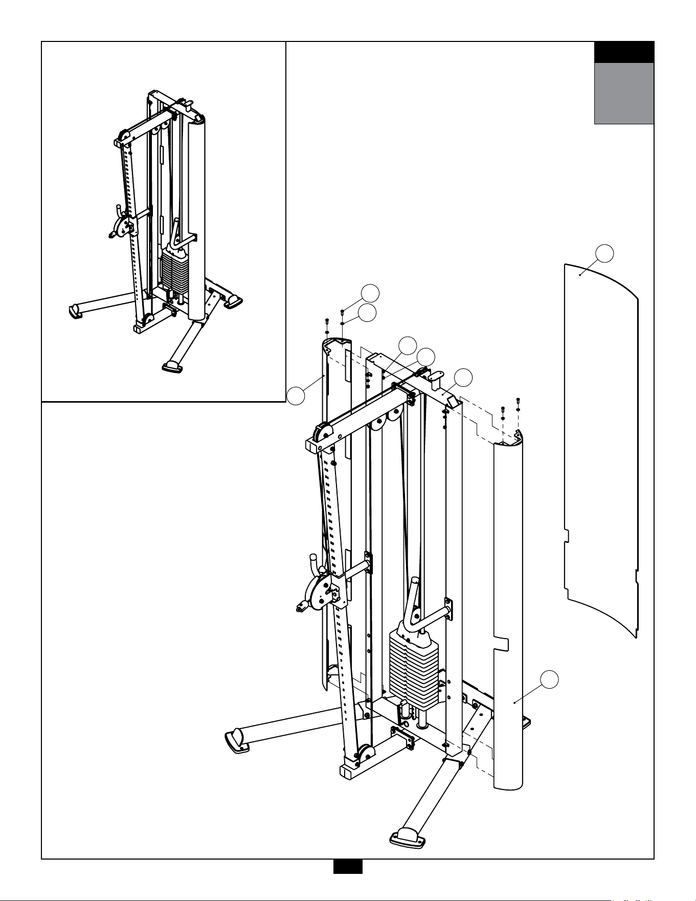
4A. AttachShortMetalShrouds(WB)andLongMetalShrouds(WC) to
WeightStackFrame(WA)using:
4 - (#10) M8X25mm Button Head Cap Screw
8 - (#52) M8 Flat Washer
4 - (#42) M8 Nylon Lock Nut
4B. BendthePlasticShrouds(WF)andinsertthemtotheside
slotsoftheMetalShrouds(WB & WC).
31
STEP
4
STEP
4
WF
WC
WB
10
52
52
42
WA
AboveshowsStep4assembledandcompleted.
STEP
4
WF
WC
WB
10
52
52
42
WA

32
STEP
5
Be careful to assemble all components
in the sequence they are presented.
NOTE:
Wrench tighten ALL hardware at the end of Step 5A. Some components may be
pre-assembled. Nylon lock nuts will not fully screw onto bolts, they must be wrench
tighten to fully go on.
5A. AttachLeft&RightBraces(G & F)toWeightStackFrame(WA)and
Left&RightBaseFrame(A & B)using:
8 - (#8) M10X30mm Hex Head Bolt
8 - (#51) M10 Flat Washer
5B. BendthePlasticShrouds(WE)andinsertthemtotheside
slotsoftheMetalShrouds(WB & WC).
5C. AttachTopShroud(WG)toWeightStackFrame(WA)using:
3 - (#11) M6X16mm Phillips Head Screw
3 - (#53) M6 Flat Washer
33
STEP
5
AboveshowsStep5assembledandcompleted.
WG
11
53
WE
G
F
51
8
51
8
A
B WA
90
89
88
68
66
J
STEP
5
WG
11
53
WE
G
F
51
8
51
8
A
B WA
90
89
88
68
66
J
STEP
5

34
STEP
6
Be careful to assemble all components
in the sequence they are presented.
NOTE:
Finger tighten all hardware in this step. DO NOT wrench tighten unless instructed.
Some components may be pre-assembled. Nylon lock nuts will not fully screw onto
bolts, they must be wrench tighten to fully go on.
6A. AttachLeft&RightBaseFrames(A & B)toRearBaseFrame(C)using:
4 - (#1) M12X110mm Hex Head Bolt
8 - (#50) M12 Flat Washer
4 - (#40) M12 Nylon Lock Nut
2 - (D) Steel Plate
6B. AttachWeightStackFrame(WH)toLeft&RightBaseFrame(A & B)
using:
4 - (#2) M12X105mm Hex Head Bolt
8 - (#50) M12 Flat Washer
4 - (#40) M12 Nylon Lock Nut
6C. AttachFrontBaseFrame(H)toWeightStackFrame(WH)using:
4 - (#3) M12X35mm Hex Head Bolt
8 - (#50) M12 Flat Washer
4 - (#40) M12 Nylon Lock Nut
6D. AttachTopFrame(K)toWeightStackFrame(WH)using:
4 - (#3) M12X35mm Hex Head Bolt
8 - (#50) M12 Flat Washer
4 - (#40) M12 Nylon Lock Nut
STEP
6
AboveshowsStep6assembledandcompleted.
35

36
STEP
7
Be careful to assemble all components
in the sequence they are presented.
NOTE:
Finger tighten all hardware in this step. DO NOT wrench tighten unless instructed.
Some components may be pre-assembled. Nylon lock nuts will not fully screw onto
bolts, they must be wrench tighten to fully go on.
7A. AttachGuidPost(X)toTop&BaseFrame(H & K)using:
2 - (#5) M10x90mm Hex Head Bolt
4 - (#51) M10 Flat Washer
2 - (#41) M10 Nylon Lock Nut
7B. InstallChromeGuideRods(WD)intotheholesintheWeightStackFrame(WA).
7C. InstallWeightRisers(#87) & RubberDonuts(#67)andslidetothebottom
oftheGuideRods
Important Notes:
1. Install the rod ends with side holes into the bottom section of the Weight
Stack Frame.
2. If 20pcs of weight plates are to be installed, do not install Weight Risers (87)
7D. TiltGuideRods(WD) awayfromtheWeightStackFrame(WA) andinstall15pcs
ofweightplates.Becarefultoholdguiderodssteadilywheninstalling
weightplates.
7E. InstallTopPlate&SelectorRodAssembly(#83)ontotheGuideRods(WD) .
7F. InstallWeightStackPin(#85)usingthekeyringendthroughtheSwivelPully
Bracket(#82).
7G. InstallTwo1/2”FlangeHexNut(#44) &SwivelPulleyBracket(#82)ontotheGuide
Rods(WD) .
7H. InstallShaftCollars(#81)ontotheGuideRodssotheyaredirectlybelowtheguide
rodholesintheuppersectionoftheWeightStackFrame.
7J. SlideShaftCollars(#81)upwardsotheylocktheguiderodsinto
positionbytighteningthefourM8x8mmSetScrews(#12)
37
STEP
7
AboveshowsStep7assembledandcompleted.
Note:
Risers(#87)arenotnecessaryif
20pcsofweightplatesaretobe
installed

38
STEP
8
Be careful to assemble all components
in the sequence they are presented.
NOTE:
Finger tighten all hardware in this step. DO NOT wrench tighten unless instructed.
Some components may be pre-assembled. Nylon lock nuts will not fully screw onto
bolts, they must be wrench tighten to fully go on.
8A. InstallCable(#92)whileinstallingFourLargePulleys(#63)and
FourSmallPulleys(#64) intoFramesasshownin
Step3Drawingusing
1 - (#6) M10X55mm Hex Head Bolt
7 - (#7) M10X50mm Hex Head Bolt
16 - (#51) M10 Flat Washer
8 - (#41) M10 Nylon Lock Nut
1 - (#78) Bracket
8B. AttachTwoHandles(N)toWeightStackFrame(WA)using:
4 - (#8) M10X30mm Hex Head Bolt
4 - (#51) M10 Flat Washer
39
STEP
8
AboveshowsStep8assembledandcompleted.

40
STEP
9
Be careful to assemble all components
in the sequence they are presented.
NOTE:
Finger tighten all hardware in this step. DO NOT wrench tighten unless instructed.
Some components may be pre-assembled. Nylon lock nuts will not fully screw onto
bolts, they must be wrench tighten to fully go on.
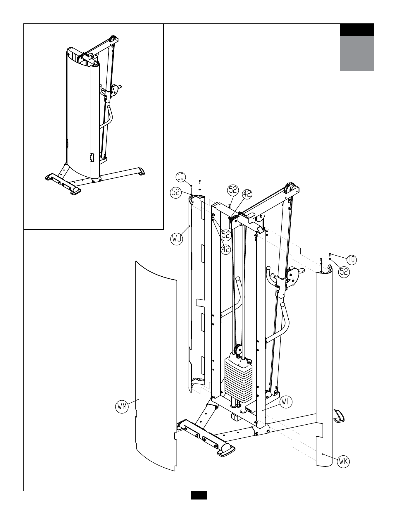
9A. AttachShortMetalShrouds(WJ)andLongMetalShrouds(WK) to
WeightStackFrame(WH)using:
4 - (#10) M8X25mm Button Head Cap Screw
8 - (#52) M8 Flat Washer
4 - (#42) M8 Nylon Lock Nut
9B. BendthePlasticShrouds(WM)andinsertthemtotheside
slotsoftheMetalShrouds(WJ & WK).
41
STEP
9
AboveshowsStep9assembledandcompleted.

42
STEP
10
Be careful to assemble all components
in the sequence they are presented.
NOTE:
Wrench tighten ALL hardware at the end of Step 5A. Some components may be
pre-assembled. Nylon lock nuts will not fully screw onto bolts, they must be wrench
tighten to fully go on.
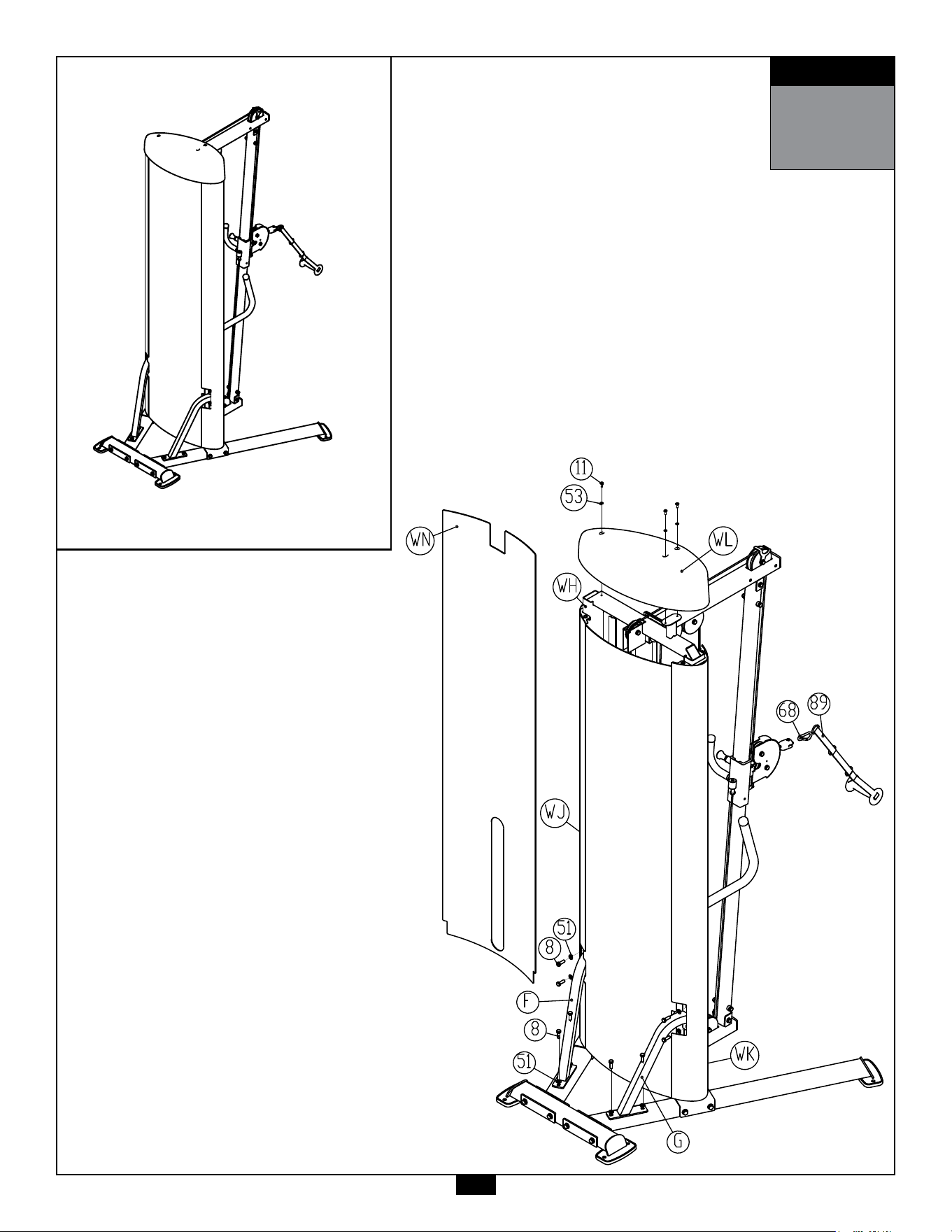
10A. AttachLeft&RightBraces(G & F)toWeightStackFrame(WA)and
Left&RightBaseFrame(A & B)using:
8 - (#8) M10X30mm Hex Head Bolt
8 - (#51) M10 Flat Washer
10B. BendthePlasticShrouds(WN)andinsertthemtotheside
slotsoftheMetalShrouds(WJ & WK).
10C. AttachTopShroud(WL)toWeightStackFrame(WA)using:
3 - (#11) M6X16mm Phillips Head Screw
3 - (#53) M6 Flat Washer
43
STEP
10
AboveshowsStep10assembledandcompleted.

44
STEP
11
Be careful to assemble all components
in the sequence they are presented.
NOTE:
Wrench tighten ALL hardware at the end of each step. Some components may be
pre-assembled. Nylon lock nuts will not fully screw onto bolts, they must be wrench
tighten to fully go on.
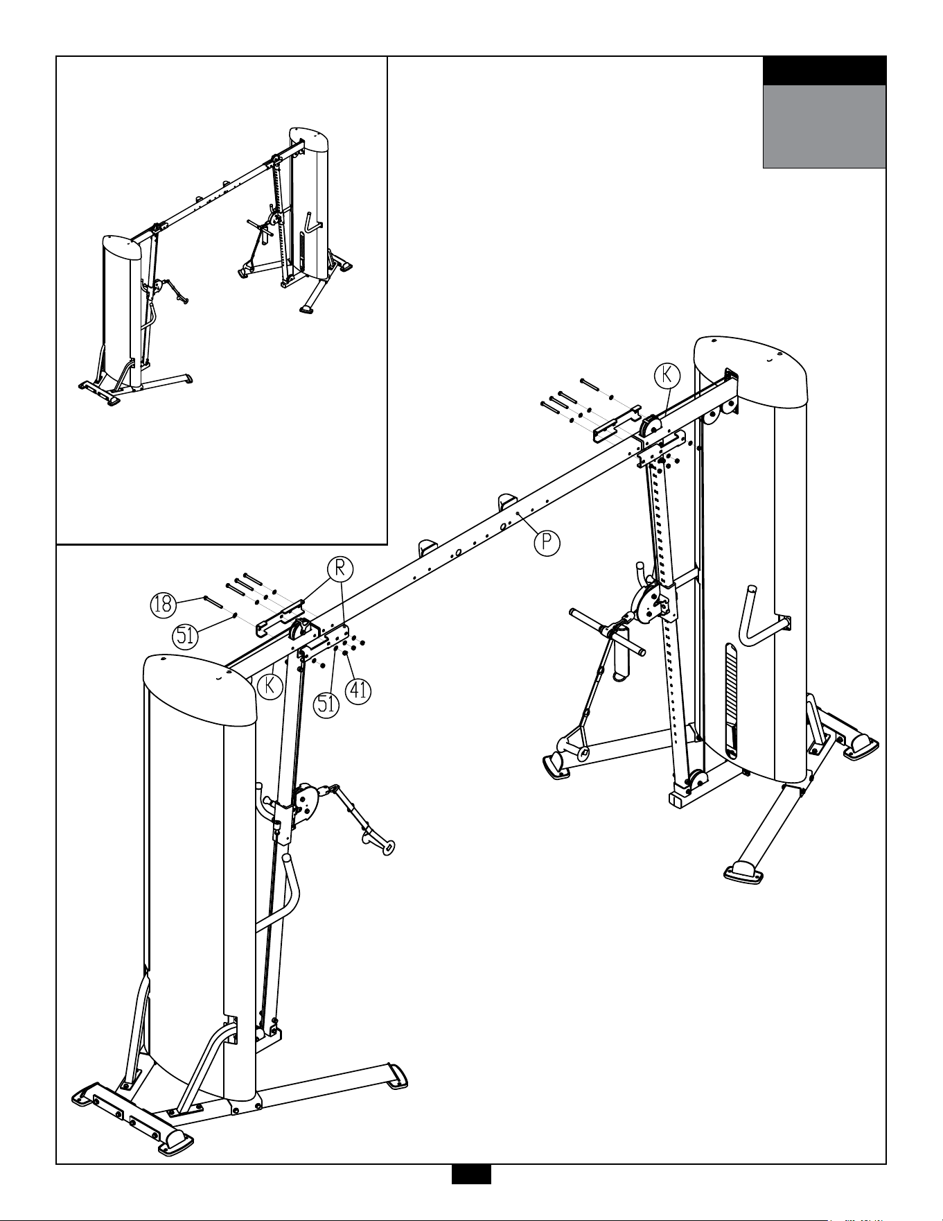
11A. AttachCrossMember(P)toTopFrames(K) ofthemachinesusing:
8 - (#18) M10X105mm Hex Head Bolt
16 - (#51) M10 Flat Washer
8 - (#41) M10 Nylon Lock Nut
4 - (R) Bracket
45
STEP
11
Aboveshows Step11 assembledandcomplet-

46
STEP
12
Be careful to assemble all components
in the sequence they are presented.
NOTE:
Wrench tighten ALL hardware at the end of each step. Some components may be
pre-assembled. Nylon lock nuts will not fully screw onto bolts, they must be wrench
tighten to fully go on.
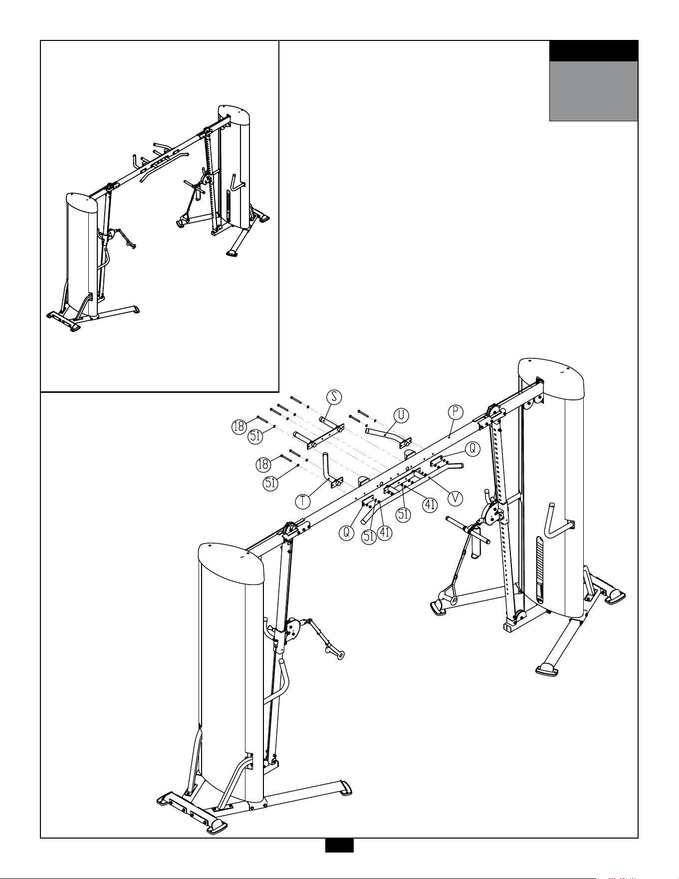
12A. AttachPullUpBars(S & V)toCrossMember(P)using:
4 - (#18) M10X105mm Hex Head Bolt
8 - (#51) M10 Flat Washer
4 - (#41) M10 Nylon Lock Nut
12B. AttachChinUpBars(T & U)toCrossMember(P)using:
4 - (#18) M10X105mm Hex Head Bolt
8 - (#51) M10 Flat Washer
4 - (#41) M10 Nylon Lock Nut
2 - (#Q) Steel Plate
47
STEP
12
AboveshowsStep12assembledandcomplet-
48
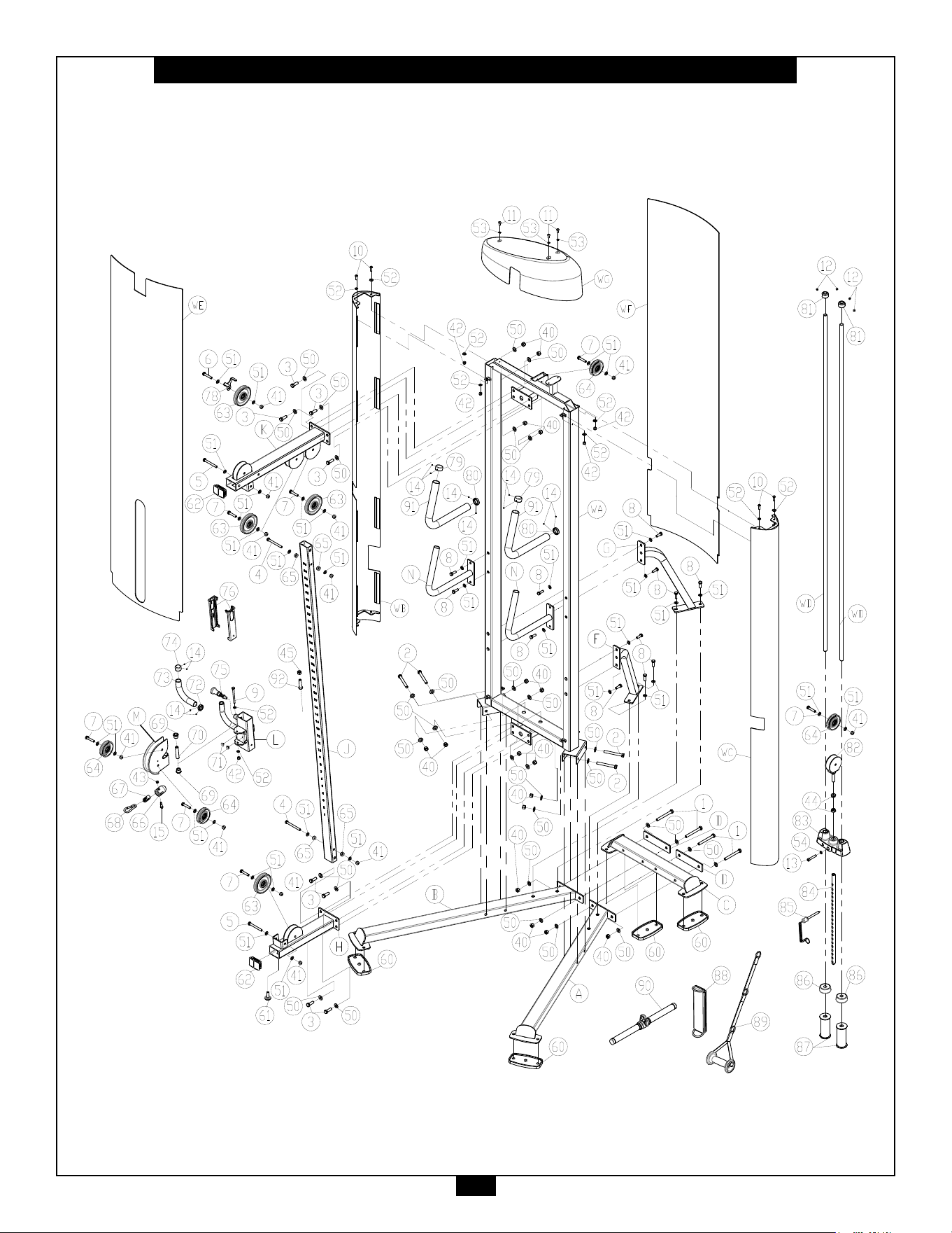
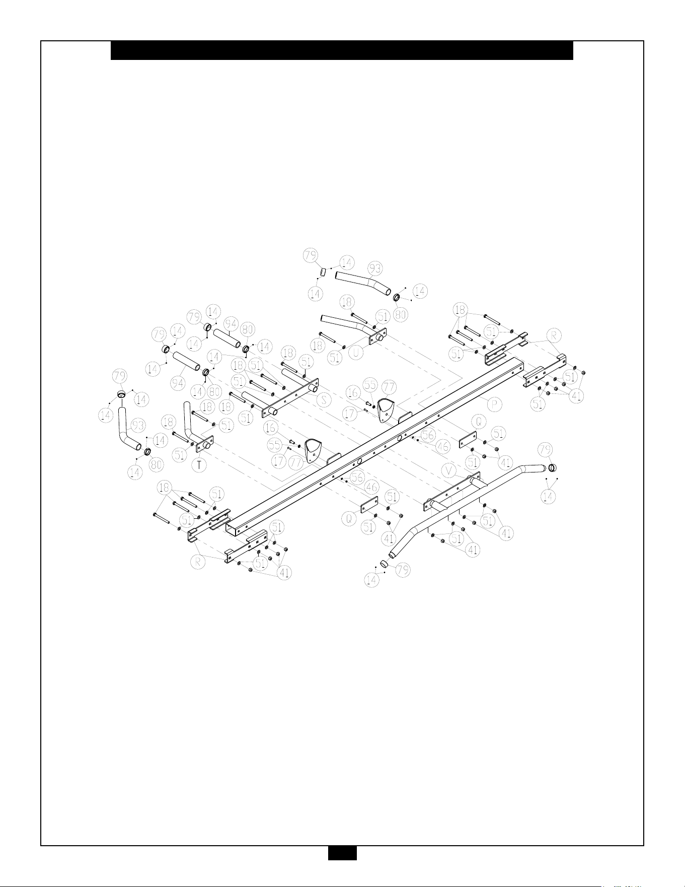
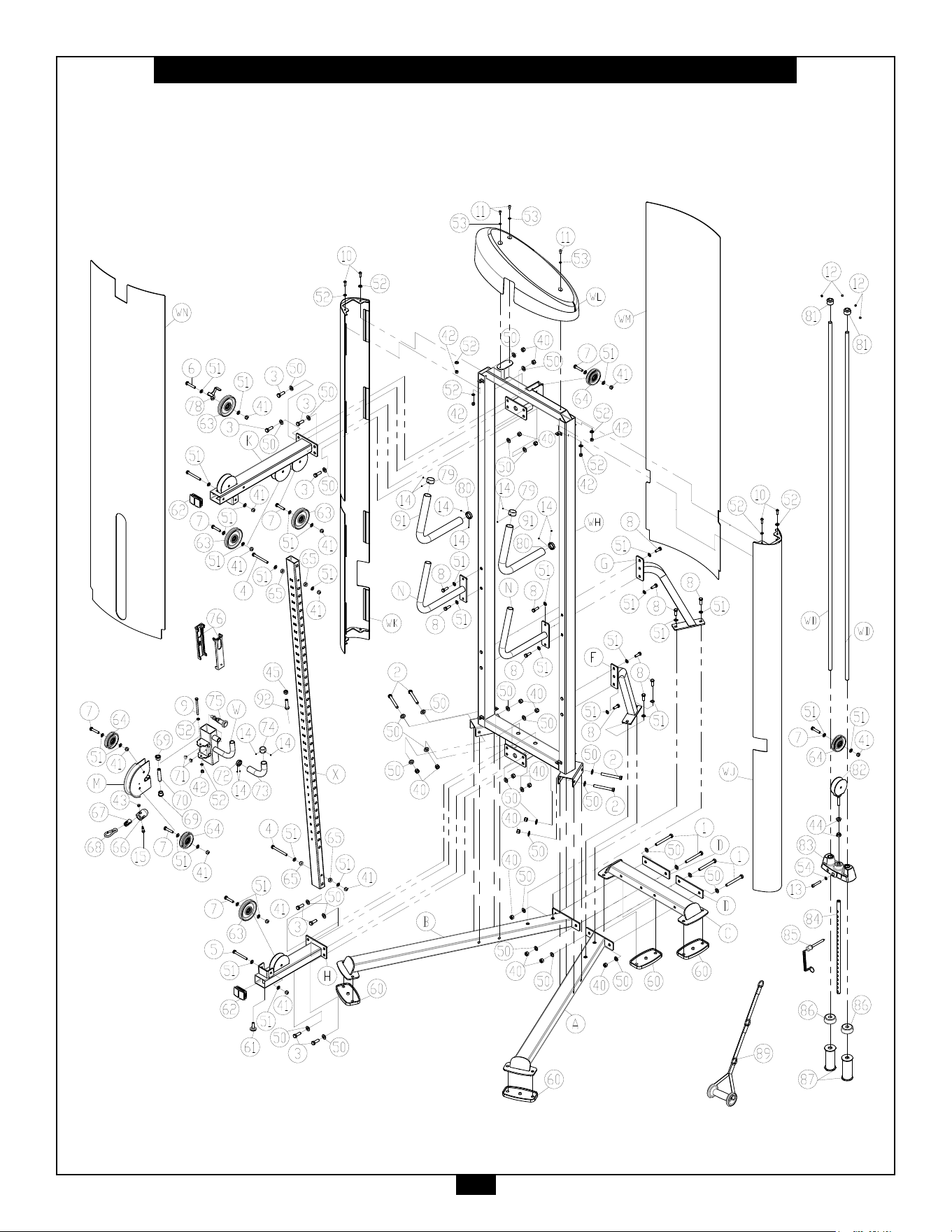
S2CCO Exploded View
49
S2CCO Exploded View (Continue)
50
S2CCO Exploded View (Continue)

51
Notes
PCL Badge Location

1900S.DesPlainesAve.
ForestPark,Il60130
Phone:(708)427-3555
Fax:(708)427-3556
Hours:M-F8:30-5:00CST
www.bodysolid.com
Copyright 2009. Body-Solid. All rights reserved. Body-Solid reserves the right to change design and specications when we feel it will improve the product.
Body-Solid machines maintain several patented and patent pending features and designs. All rights reserved on all design patents and utility patents.
PLEASE WRITE YOUR SERIAL NUMBER IN THE BOXES BELOW
S/N# 011861-��-��-����-����
S2CCO