
Operator’s Manual
www.mechmaxx.com
WARRANTY


MAX Performance, MAX Value, MAX Support
that’s Flail Mower
Enhanced design features come standard
Engineered for the best user experience
Quality metal parts are used instead of plastic
A robust warranty supports all products
Budget-friendly prices make it practical
TABLE OF CONTENTS
TABLE OF CONTENTS
SPECIFICATIONS
SAFETY SIGNS
IMPORTANT SAFETY INFORMATION
1
2
TRANSPORTING
MOWING INSTRUCTIONS
13
13
OPERATING INSTRUCTIONS
13
LEVELING THE MOWER
CUTTING HEIGHT ADJUSTMENT
14
14
3-POINT HITCH ADJUSTMENTS
14
MAINTENANCE
15
KNIFE REPLACEMENT
15
V-BELT INSTALLATION
15
BOLT TORQUE
18
ENGLISH TORQUE SPECIFICATIONS
18
METRIC TORQUE SPECIFICATIONS
19
STORAGE
15
LUBRICATION
15
SAFETY AT ALL TIMES
LOOK FOR THE SAFETY ALERT SYMBOL
BE AWARE OF SIGNAL WORDS
4
4
4
FOR YOU PROTECTION
4
SHUTDOWN AND STORAGE
4
USE SAFETY LIGHTS AND DEVICES
4
TRANSPORT MACHINERY SAFELY
5
KEEP RIDERS OFF MACHINERY
5
PRACTICE SAFE MAINTENANCE
5
PREPARE FOR EMERGENCIES
5
WEAR PROTECTIVE EQUIPMENT
5
AVOID HIGH PRESSURE FLUIDS HAZARD
5
APPLICATION
USING THIS MANUAL
TERMINOLOGY
DEFINITIONS
OWNER ASSISTANCE
SERIAL NUMBER PLATE
3
4
6
6
6
6
TRACTOR REQUIREMENTS
PACKING DESCRIPTION
ASSEMBLY
7
7
7
9
6
6
6
DRIVELINE INSTALLATION 11
INTRODUCTION
ASSEMBLY AND SET-UP
13
OPERATING INSTRUCTIONS
14
ADJUSTMENTS
15
MAINTENANCE AND LUBRICATION
17
TROUBLESHOOTING
18
APPENDIX
20
WARRANTY
21
PARTS ILLUSTRATION
22
VAM FLAIL MOWER PARTS LIST
Your new Flail Mower offers quality construction, and is
easy and safe to operate. With proper use and care, it is
designed to give you many years of dependable service.
Prepare to experience the durability to take on any job
with the ease, portability, and convenience of your new
Flail Mower !
1
www.mechmaxx.com
TABLE OF CONTENTS

SPECIFICATIONS
2
www.mechmaxx.com
SPECIFICATIONS
Power Required
Working Width
Overall Width
Blade Ground Clearance
Max. Cutting Diameter
Offset Distance From The Center (Maximum)
Tilt-Up Angle
Tilt-Down Angle
Number Of Blades
Blade Type
Size of Blades
Blade Weight
Blade Material
Rotor Bearing
Rotor Diameter
Blade Swing Diameter
Rotor Thickness
Rotor Shaft Speed
Hydraulic Fittings Size
Hydraulic Hoses Quantity
Drive Type
Spline End
Driveline Shaft Length
PTO Shaft Speed
Deck Thickness
Side Plate Thickness
3-Point Hitch
Gearbox Oil Type
Number of Belts
Belt Size
Finish
Warranty
Dimensions (L x WxH)
Weight (N.W./G.W.)
25-50 hp
48 in
56 in
0.65 in-2 in
1.5 in
69 in
90°
60°
20
Hammer
3.5x3.2x1.6 in
0.9 Ibs
Cast Steel
SKF Bearing
4.3 in
14 in
0.3 in
2356 rpm
G1/2 in
4
Belt Drive
1.375 in Z6
T6-LF-63 With Shear Bolt; 63-77 in [05B-1600]
540 rpm
0.16 in
0.25 in
CAT 1
85W-90
3
V Belt 17x991
Powder Coating
1 Year
56x27.5x28 in
613/696 Ibs
25-60 hp
60 in
64 in
77 in
24
30-60 hp
65 in
72 in
85 in
28
64 x 27.5 x 28in
673/738 lbs
72 x 27.5 x 28 in
701/820 lbs
Model VAM48 VAM60 VAM65

3
www.mechmaxx.com
SAFETY SIGNS
The rating plate on your machine may show symbols. These represent important information about the product or instruc-
tions on its use.
SAFETY SIGNS
The PTO Driveline MUST be
measured and cut (if required) as
per the Owner's Manual.
Failure to do so will result in
damage to both the tractor
and the implement.
ENGAGE TRACTOR
CLUTCH SLOWLY
DURING START UP OR
DAMAGE WILL OCCUR.
KEEP PTO SHAFT
WITH 25°OF LEVEL
DURING OPERATION.
All driveline guards, tractor, and equipment
shields in place.
ROTATING DRIVELINE
CONTACT CAN CAUSE DEATH
KEEP AWAY!
DO NOT OPERATE WITHOUT :
DO NOT go under frame when rotor is turning or engine
is running. Keep others away.
ROTATING KNIVES HAZARD
Disconnect & lockout power source BEFORE adjusting
or servicing.
Keep hands, feet, hair, and clothing away from moving
parts.
Do not open or remove safety shields while
engine is running.
Drivelines securely attached at both ends.
Driveline guards that turn freely on driveline.
ROTATING
BLADES
KEEP HANDS
AWAY
Read and understand
operators manual
before using this
machine.
High Pressure Fluid Hazard.
High pressure fluid leak will pierce skin.
Release pressure before working on system.
Fluid injected into skin will injure or kill.
Detect leaks with wood or cardboard.
Wear sturdy gloves and goggles.
NEVER use fingers.
Fluid injected in skin must be surgically
removed by trained doctor immediately or
gangrene will result.
To prevent serious injury or death from rotating knives:
Read and understand Operator's manual before using.
Operate with guards installed and in good condition.
Operate only with tractor equipped with ROPS and
seatbelts.
Keep away from moving parts.
Stop engine, set brake and wait for all moving parts to
stop before dismounting.
Be sure lights and reflectors required by law are clean
and in good working order before transporting.
Do not allow children to operate mower.
Travel with SMV and lights that follow local codes.
Clean debris from mowing area.
Do not operate in the raised position.
Support securely before working beneath unit.
Review safety instructions annually.
Do not permit riders on the tractor or mower. Never carry
child on tractor seat.
To Prevent Serious Injury Or Death:
PINCH POINT
HAZARD
Keep clear
GUARD MISSING
WHEN THIS IS VISIBLE
DO NOT OPERATE
ENTANGLEMENT HAZARD
BELT DRIVE:
HAND AND ARM
ENTANGLEMENT
HAZARD.
FLYING OBJECTS
HAZARD
Keep clear.
Relieve pressure before disconnecting lines.
Do Not use hands to check for leaks.
Consult physician immediatly if skin
penetration occurs.
HIGH PRESSURE FLUID
HAZARD

4
www.mechmaxx.com
SAFETY AT ALL TIMES
LOOK FOR THE SAFETY ALERT SYMBOL
BE AWARE OF SIGNAL WORDS
FOR YOU PROTECTION
DANGER
IMPORTANT SAFETY INFORMATION
SAFETY
Thoroughly read and understand the instructions given in
this manual before operation. Refer to the "Safety Decal",
read all instructions noted on them.
A signal word designates a degree or level of hazard
seriousness. The signal words are:
Do not allow anyone to operate this equipment who has
not fully read and comprehended this manual and who has
not been properly trained in the safe operation of the
equipment.
Indicates an imminently hazardous situation
which, if not avoids, will result in death or
serious injury. This signal word is limited to the
most extreme situations, typically for machine
components that, for functional purpose,
cannot be guarded.
• Operator should be familiar with all functions of the
unit.
• Operate implement from the driver's seat only.
• Make sure all guards and shields are in place and
secured before operating the implement.
• Do not leave tractor or implement unattended with
engine running.
• Dismounting from a moving tractor could cause serious
injury or death.
• Do not stand between tractor and implement during
hitching.
• Keep hands, feet, and clothing away from power-driven
parts.
• Wear snug fitting clothing to avoid entanglement with
moving parts.
• Watch out for wires, trees, etc., when raising imple-
ment. Make sure all persons are clear of working area.
• Turning tractor too tight may cause implement to ride
up on wheels. This could result in injury or equipment
damage.
The SAFETY ALERT SYMBOL indicates there is a potential
hazard to personal safety involved and extra safety
precaution must be taken. When you see this symbol, be
alert and carefully read the message that follows it. In
addition to design and configuration of equipment, hazard
control and accident prevention are dependent upon the
awareness, concern, prudence and proper training of
personnel involved in the operation, transport, mainte-
nance and storage of equipment.
• Thoroughly read and understand the "safety label"
section, read all instructions noted on them.
SHUTDOWN AND STORAGE
• Lower machine to ground, put tractor in park, turn off
engine, and remove the ignition key.
• Detach and store implements in a area where children
normally do not play. Secure implement by using
USE SAFETY LIGHTS AND DEVICES
• Slow moving tractors, self-propelled equipment, and
towed implements can create a hazard when driven on
public roads. They are difficult to see, especially at
night.
• Flashing warning lights and turn signals are recom-
mended whenever driving on public roads. Use lights
and devices provided with implement.
WARNING
Indicates a potentially hazardous situation
which, if not avoided, could result in death or
serious injury, and includes hazards that are
exposed when guards are removed. It may also
be used to alert against unsafe practices.
CAUTION
Indicates a potentially hazardous situation
which, if not avoided, may result in minor or
moderate injury. It may also be used to alert
against unsafe practices.

5
www.mechmaxx.com
SAFETY
• Comply with state and local laws.
• Maximum transport speed for implement is 20 mph. Do
not exceed. Never travel at a speed which does not
allow adequate control of steering and stopping. Some
rough terrain require a slower speed.
• Sudden braking can cause a towed load to swerve and
upset. Reduce speed if towed load is not equipped with
brakes.
• Use the following maximum speed - tow load weight
ratios as a guideline: 20 mph when weight is less than
or equal to the weight of tractor. 10 mph when weight
is double the weight of tractor.
• IMPORTANT: Do not tow a load that is more than double
the weight of tractor.
• Riders obstruct the operator’s view, they could be
struck by foreign objects or thrown from the machine.
• Never allow children to operate equipment.
• Understand procedure before doing work. Use proper
tools and equipment. refer to Operator's Manual for
additional information.
• Work in a clean dry area.
• Lower the implement to the ground, put tractor in park,
turn off engine, and remove key before performing main-
tenance.
• Allow implement to cool completely.
• Do not grease or oil implement while it is operation.
• Inspect all parts. Make sure parts are in good condition
and installed properly.
• Remove buildup of grease, oil or debris.
• Remove all tools and unused parts from implement
before operation.
• Be prepared if a fire starts.
• Keep a fist aid kit and fire extinguisher handy.
• Keep emergency numbers for doctor, ambulance, hospi-
tal and fire department near phone.
TRANSPORT MACHINERY SAFELY
KEEP RIDERS OFF MACHINERY
PRACTICE SAFE MAINTENANCE
• Escaping fluid under pressure can penetrate the skin
causing serious injury.
• Avoid the hazard by relieving pressure before discon-
necting hydraulic lines.
• Use a piece of paper or cardboard, not body parts, to
check for suspected leaks. Wear protective gloves and
safety glasses or goggles when working with hydraulic
systems.
• If an accident occurs, see a doctor immediately. Any
fluid injected into the skin must be treated within a few
hours or gangrene may result.
AVOID HIGH PRESSURE FLUIDS HAZARD
PREPARE FOR EMERGENCIES
• Protective clothing and equipment should be worn.
• Wear clothing and equipment appropriate for the job.
Avoid loose fitting clothing.
• Prolonged exposure to loud noise can cause hearing
impairment or hearing loss. Wear suitable hearing
protection such as earmuffs or earplugs.
• Operating equipment safely requires the full attention
of the operator. Avoid wearing radio headphones while
operating machinery.
WEAR PROTECTIVE EQUIPMENT

6
www.mechmaxx.com
APPLICATION
USING THIS MANUAL
TERMINOLOGY
INTRODUCTION
INTRODUCTION
MechMaxx welcomes you to the growing family of new
product owners. This implement has been designed with
care and built by skilled workers using quality materials.
Proper assembly, maintenance, and safe operating
practices will help you get years of satisfactory use from
the machine.
The Flail Mowers are designed for Category 1- three point
hitch or Quick-Hitch System mounting. These Fixed Bar
Flail Mowers are ideal for ripping, leveling, finish grading,
and backfilling applications at feedlots, outdoor arenas,
building sites, and maintenance operations on farm and
ranch lanes or roadways.
SERIAL NUMBER PLATE
For prompt service always use the serial number and
model number when ordering parts from your dealer. Be
sure to include your serial and model numbers in corre-
spondence also.
• This Operator's Manual is designed to help familiarize
you with safety, assembly, operation, adjust-
ments,troubleshooting, and maintenance. Read this
manual and follow the recommendations to help ensure
safe and efficient operation.
• The information contained within this manual was
current at the time of printing. Some parts may change
slightly to assure you of the best performance.
• To order a new Operator's or Parts Manual contact your
authorized dealer.
" Right" or "Left" as used in this manual is determined by
facing the direction the machine will operate while in use
unless otherwise stated.
DEFINITIONS
OWNER ASSISTANCE
Note: A special point of information that the operator
must be aware of before continuing.
Important: A special point of information related to its
preceding topic. The intention is that this information
should be read and noted before continuing.
The Warranty Registration card should be filled out by the
dealer at the time of purchase. This information is neces-
sary to provide you with quality customer service. If
customer service or repair parts are required contact a
dealer.
A dealer has trained personnel, repair parts and equip-
ment needed to service the machine.The parts on your
machine have been specially designed and should only be
replaced with genuine parts.
7
www.mechmaxx.com
ASSEMBLY AND SET-UP
ASSEMBLY AND SET-UP
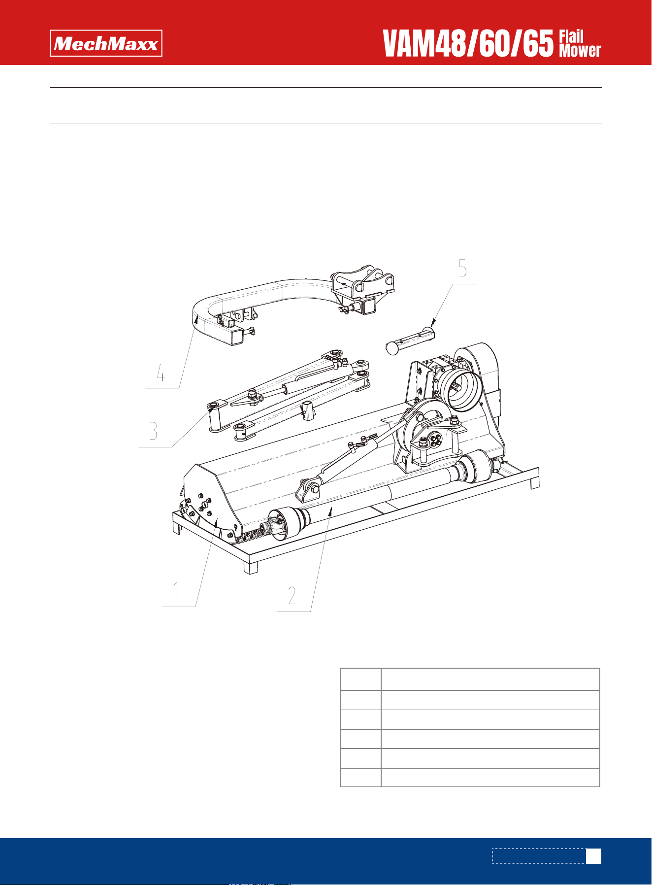
Item Description
1
2
3
4
5
Main body of the mower
W-02-05B-1600A with safety drive shaft
Swing arms sub-assembly
Suspension components
Support Leg assembly
TRACTOR REQUIREMENTS
This mower is designed with a 3-Point category I hitch. Tractor horse power rating should not exceed 80 PTO horse power.
1. Remove and check
Remove the packing, check goods without defect and omission.
2. Packing List
The detailed packing list of the mower and
accessory as the following table.
Figure 1-1: The Mower and Accessory in Package
PACKING DESCRIPTION
8
www.mechmaxx.com
ASSEMBLY AND SET-UP
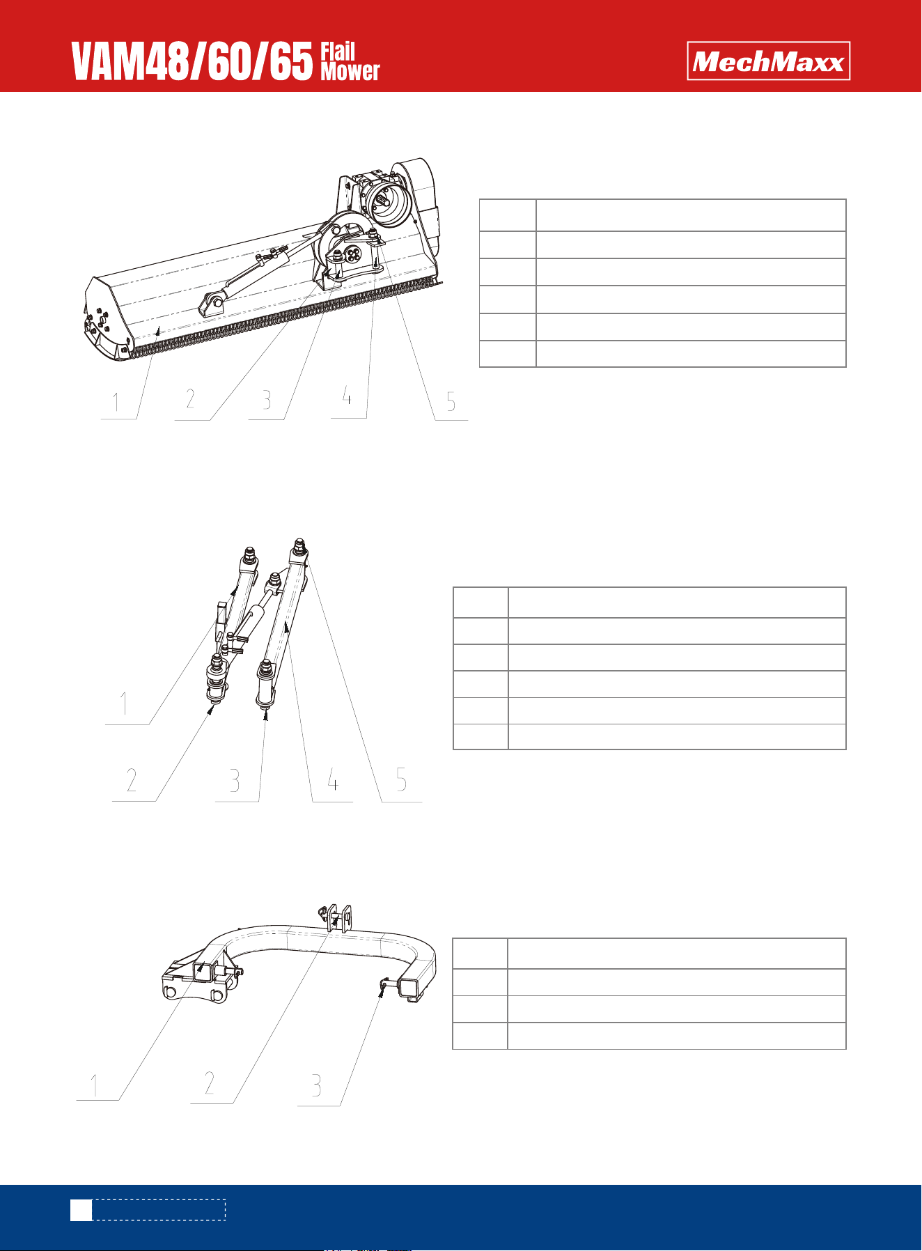
The detailed description of main body of the mower and fittings
The detailed description of swing arms sub-assembly and fittings
The detailed description of hitch tube amendment and fittings
Figure 1-2: Main Body of The Mower and Fittings
Figure 1-3: Swing Arms Sub-Assembly and Fittings
Figure 1-4: Hitch Tube Amendment and Fittings
Item Description
1
2
3
4
5
Main body of the mower
AGL165COS.8A Flip Frame Welding Assembly
AGL165.6 short shafts
AGL165.2AGL165.2B
B-G00889A-24 Nut M24
Item Description
1
2
3
4
5
AGL165.4 Small Rotating Arm Welding Assembly
AGL165.2B Long Sales 2
AGL165.2 Long Sales
AGLJA125.3 Large Rotating Arm Welding Assembly
B-G00889A-24 Nut M24
Item Description
1
2
3
AGL165COS.1A Suspension Frame Welding Assembly
Hanging pin on NCM175.17
B-G043290-10 locking pin 10
9
www.mechmaxx.com
ASSEMBLY AND SET-UP
INSTALLATION WIZARD
The installation wizard will guide you to finish the final assembly of your new mower easily.
1. TOOL REQUIRED
2. TORQUE APPLICATION
3. ASSEMBLY
Air impact wrench with 46mm sleeve
T type socket wrench 13mm
T type socket wrench 18mm
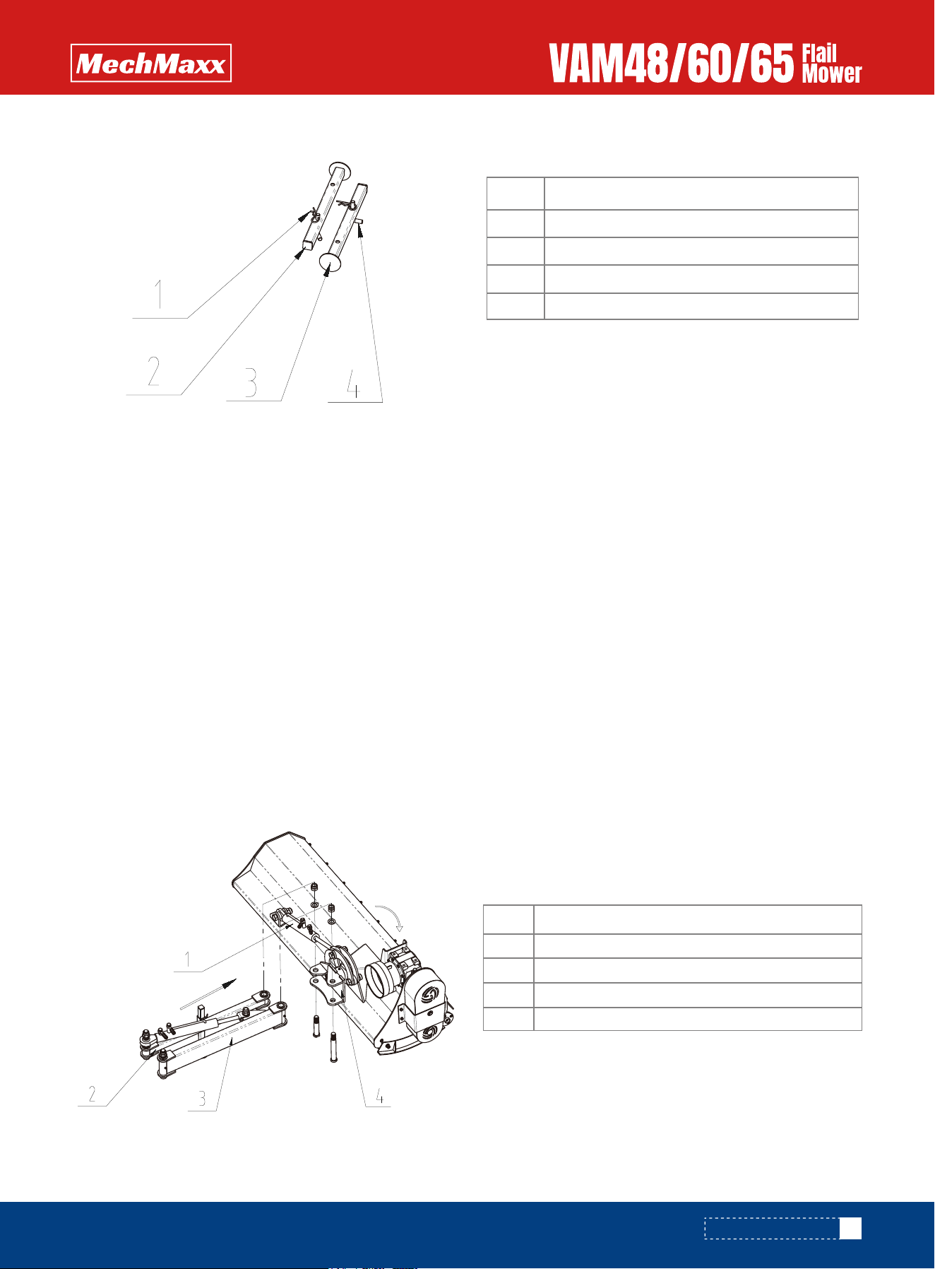
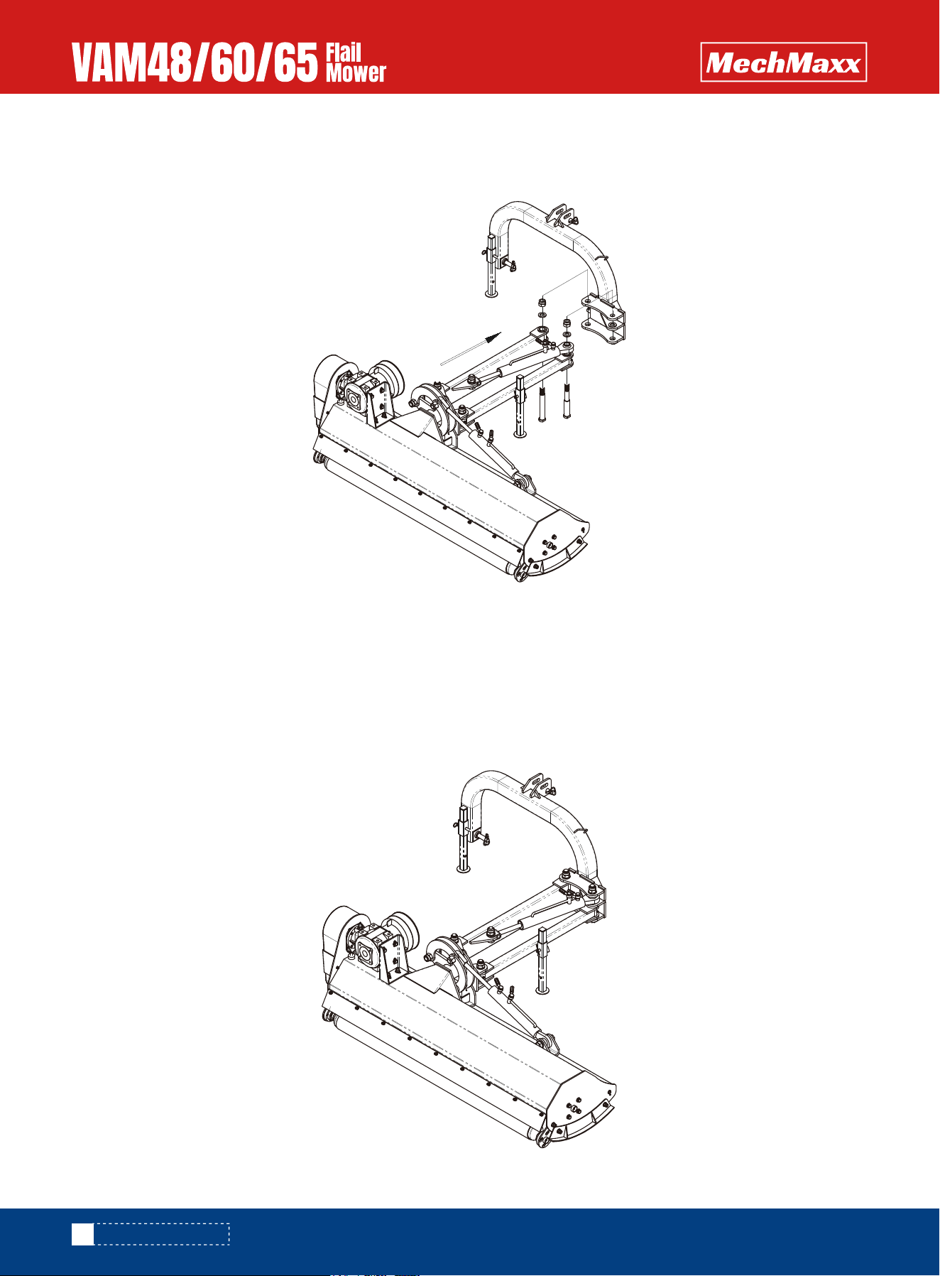
Step1: Installing Swing Arms Sub-Assembly
Remove the packaging of swing arms sub-assembly and fittings. Push swing arms sub-assembly into the overturning
bracket assembly as shown in figure1-6. Fix it with 2pcs of swing arm pins-longer, 2pcs of knockout M30x2. Tighten
knockout completely
Refer to bolt torque in Section 7 Appendix.
The detailed description of Support Leg Assembly
Figure 1-5: Support Leg Assembly
Item Description
1
2
3
4
EFGC125.110 R Sales 3.2
W-08-F40 square rubber cover 40
AGL165.5 support foot welding assembly
EFGC175.37 support foot pin
Item Description
1
2
3
4
AGL165.12A Flip Cylinder
AGL165.4 Small Rotating Arm Welding Assembly
AGLJA125.3 Large Rotating Arm Welding Assembly
AGL165COS.8A Flip Frame Welding Assembly
Figure 1-6: Installing Swing Arms Sub-Assembly
10
www.mechmaxx.com
ASSEMBLY AND SET-UP
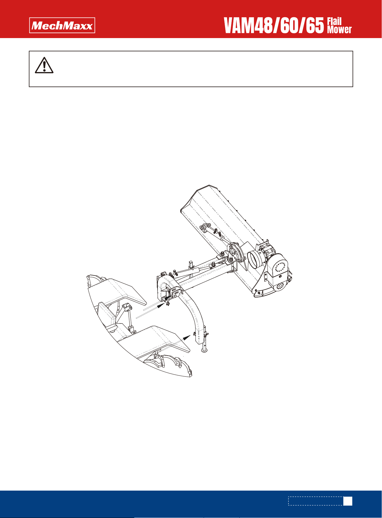
Step2: Installing Hitch Tube Amendment and Fittings
Remove the packaging of hitch tube amendment and fittings. Fix hitch tube amendment to swing arms sub-assembly
with 1pcs of swing arm pin-shorter, 1pcs of knockout M30x2. Tighten knockout completely.
Step3: Installing Rake Sub-Assembly
Remove the packaging of rake sub-assembly. Insert rake amendment-longer into the tube on swing arm amendment-l as
well as rake pin and insert R pin into the hole on rake pin. Insert rake short-termism into the tube on hitch tube amend-
ment as well as rake pin and insert R pin into the hole on rake pin. Pass all oil pipes through the guide ring and fix them
with oil pipe clamps.
Note: The length of oil pipes between oil cylinders and pipe clamps shall be reserved with allowance to prevent oil pipes
from being damaged during swing arms moving left and right and main body of the mower turning up and down.
Figure 1-7: Installing Hitch Tube Amendment and Fittings
Figure 1-8: Installing Rake Sub-Assembly and Oil Pipes Fixation
11
www.mechmaxx.com
ASSEMBLY AND SET-UP
WARNING
TRACTOR HOOK-UP
DRIVELINE INSTALLATION
1. Be certain that tractor draw bar will not interfere. Move draw bar ahead or remove if required. Draw bar should also be
checked for clearance when unit is being raised for the first time.
2. Align lower link arms of tractor to hitch clevises on mower. Insert lower hitch pins into lower ball swivels and attach
link pins.
3. Attach tractor top link to upper floating hitch on mower with pin supplied. Secure with lock pin.
4. Adjust tractor top link in or out to place upper hitch pin vertically above or slightly behind lower hitch pins to allow
mower flotation. The mower should be run with the back 15 degrees lower than the front.
1. Slide driveline end with extended safety cone over spline shaft of gearbox and secure with attaching device.
2. Slide driveline over tractor’s spline PTO shaft and secure with locking device of driveline.
3. Driveline should now be moved back and forth to ensure that it is secure on the PTO shaft of the tractor and mower
gearbox.
4. Attach chain from the driveline shield to one of the upper hitch braces to ensure that the shield does not rotate.
Fill the gearbox with proper amount of gear oil before operation. Ensure that the height of the rotation
axis from the ground is greater than 700mm,otherwise one side of the mower will touch the ground
in advance, resulting in damage to the connecting plate and hinging bracket. Refer to figure 1-6.
Figure 1-9: Tractor Hook-up

12
www.mechmaxx.com
ASSEMBLY AND SET-UP
5. Should driveline require shortening:
a. Hold the half-shafts next to each other in the shortest working position andmark them.
b. Shorten inner and outer guard tubes equally.
c. Shorten inner and outer sliding profiles by the same length as the guard tubes.
d. Proper overlap is a minimum of one-half the length of each tube, with both tubes being of equal length.
e. Round off all sharp edges and remove burrs. Grease sliding profiles.
CAUTION
Tractor PTO shield and all mower guards must be always in place during operation!

13
www.mechmaxx.com
OPERATING INSTRUCTIONS
OPERATING INSTRUCTIONS
When traveling on public roads, whether
at night or during the day, use accessory
lights and devices for adequate warning to
operators of other vehicles. Comply with
all Federal, State, and local laws.
CAUTION
TRANSPORTING
MOWING INSTRUCTIONS
OPERATING INSTRUCTIONS
NOTE: Always disengage PTO before raising mower to
transport position.
Before beginning to mow, the following inspection should
be performed:
1.When raising the mower to transport position, be sure
that driveline does not contact tractor or mower. Adjust
and set the tractor's 3-point hitch lift height so that the
driveline does not contact mower deck in the fully
raised position.
2.Be sure to reduce tractor ground speed when turning,
leaving enough clearance so that the mower does not
contact buildings, trees, or fences.
3.Select a safe ground travel speed when transporting
from one area to another. When traveling on roadways,
transport in such a way that faster moving vehicles may
pass safely.
4.When traveling over rough or hilly terrain, shift tractor to
a lower gear.
1.Check oil level in gearbox.
2.Check that all plugs in gearbox have been replaced and
tightened properly.
3.Be sure all mower knives, bolts and nuts are tight.
4.Be certain all guards and shields are in place and
secure.
5.Grease driveline shaft and all other grease fittings.
6.Clear area to be mowed of rocks, branches and other
foreign objects.
7.Lower mower to ground. Set tractor throttle at approxi-
mately 1/4 open. Engage PTO to start blades rotating.
8.Operate with 540 rpm PTO tractor.
9.At first begin mowing at a slow forward speed and shift
up until the desired speed is achieved - maintaining 540
PTO rpm.
10.Mower knives will cut better at a faster blade speed
than at reduced throttle.
11.After mowing the first 50 feet, stop and check to see
that the mower is adjusted properly.
12.Do not make sharp turns or attempt to back up while
mower is on the ground.
13.Do not engage PTO with mower in the fully raised
position. Do not engage PTO at full throttle.
1.Clear area to be mowed of objects and debris that might
be picked up and thrown by the mower blades.
2.Grass is best cut when it is dry. Mowing wet grass can
cause plugging resulting in grass clumps behind the
mower.
3.Grass should be mowed frequently as shorter clippings
deteriorate faster.
4.If mowing extremely tall grass, it is best to raise
cutting height and mow the area, then lower cutting
height and mow a second time at the desired height.
Proper servicing and adjustments are the key to the long
life of any machine. With careful and systematic inspec-
tion of the mower, costly maintenance, time and repair
can be avoided.
THE GEARBOX AND TRANSMISSION ARE SHIPPED WITH-
OUT OIL.
ADD OIL BEFORE FIRST USE!
Gear Oil 85w/90
MUST ADD OIL BEFORE FIRST USE.

14
www.mechmaxx.com
ADJUSTMENTS
ADJUSTMENTS
Engage parking brake, shut off tractor,
remove key and disengage PTO before
making any height adjustments!
CAUTION
Excessive tension on the belt may lead to
premature failure of belt and drive compo-
nents. Excessive tension on the belt may
also lead to a safety hazard to the opera-
tor or bystanders.
CAUTION
Belt drive system under spring tension;
use care to avoid bodily harm!
CAUTION
LEVELING THE MOWER
NOTE: Tractor and mower should be on level ground.
Leveling can be adjusted at the tractor's 3-point arms and
center link.
CUTTING HEIGHT ADJUSTMENT
3-POINT HITCH ADJUSTMENTS
The machines cutting height depends upon the position of
the rear roller.
1.Remove the bolts that fix the roller on both sides.
2.Lift or lower both sides of roller in equal measurements.
3.Replace bolts and re-tighten.
1.Tension on the belt can be adjusted with the belt
tension bolt. Turn the bolt until desired tension is
achieved. When the belt has the correct tension the
gearbox should be adjusted so that the gearbox exten-
sion is running straight (parallel) with the flail mower.
Loosen bolts at the bottom of the gearbox and move
gearbox until gearbox extension is running straight.
2.Excessive tension on the belt may lead to premature
failure of belt and drive components.
The 3-point hitch system on this mower has been
designed for front to back flotation when mowing on
uneven terrain. Adjust tractor's top center link to place
the upper hitch pin vertically above or slightly behind the
lower hitch pins. The mower should be run with the back
15 degrees lower than the front.The hitch can also be
adjusted from side to side by turning the adjustment
handle. Turn handle until you have achieved your desired
location.
The Belt tension should be checked after the first 20
hours of use. And then every 40 hours of use.
15
www.mechmaxx.com
MAINTENANCE AND LUBRICATION
MAINTENANCE AND LUBRICATION
For safety reasons, each maintenance
operation must be performed with tractor
PTO disengaged, mower lowered com-
pletely to ground and tractor engine shut
off with ignition key removed.
• After using the mower for several hours,
check all bolts to be sure they are tight
and check drive belt tension.
• Replace any worn, damaged or illegible
safety decals by obtaining new decals
from dealer.
CAUTION
MAINTENANCE
Proper servicing and adjustment is the key to the long life
of any farm implement. With careful and systematic
inspection, you can avoid costly maintenance, time and
repair.
Driveline Shaft U-Joints
Type of Lubrication: Multi-purpose Grease
KNIFE REPLACEMENT
LUBRICATION
25
HOURS
IMPORTANT: Make sure that the knife is the same length
as the others on the mower. This will keep the rotor
rotation balanced.
V-BELT INSTALLATION
STORAGE
Belt drive system under spring tension; use care to avoid
bodily harm!
At the end of the working season or when the mower will
not be used for a long period, it is good practice to clean
off any dirt or grease that may have accumulated on the
mower and any of moving parts.
1.Remove bolt and nut.
2.Remove old knife.
3.Install new knife and existing bolt.
4.Secure with nut.
1.Clean as necessary.
2.Check knives for wear and replace if necessary.
3.Inspect mower for loose, damaged or worn parts and
adjust or replace as needed.
4.Store unit inside if possible for longer life.
5.Repaint parts where paint is worn or scratched to
prevent rust.
6.Replace all damaged or missing decals.
1.Remove belt guard fender and belt cover.
2.Disengage belt tension by loosening belt tension bolt
until belt can be removed.
3.With tension relieved from belt remove old belt from
pulleys.
4.Tighten belt tension bolt.
5.Reinstall belt guard and belt guard fender.
Roller Bearing (Both Ends)
Type of Lubrication: Multi-purpose Grease
25
HOURS
Cutter Rotor Bearing (Both Ends)
Type of Lubrication: Multi-purpose Grease
25
HOURS
Gearbox
Type of Lubrication: 85w/90
AS
REQUIRED
16
www.mechmaxx.com
MAINTENANCE AND LUBRICATION
20
HOURS
IMPORTANT: Mower should be level when checking oil in
gearbox!
Driveline Profiles
Type of Lubrication: Multi-purpose Grease
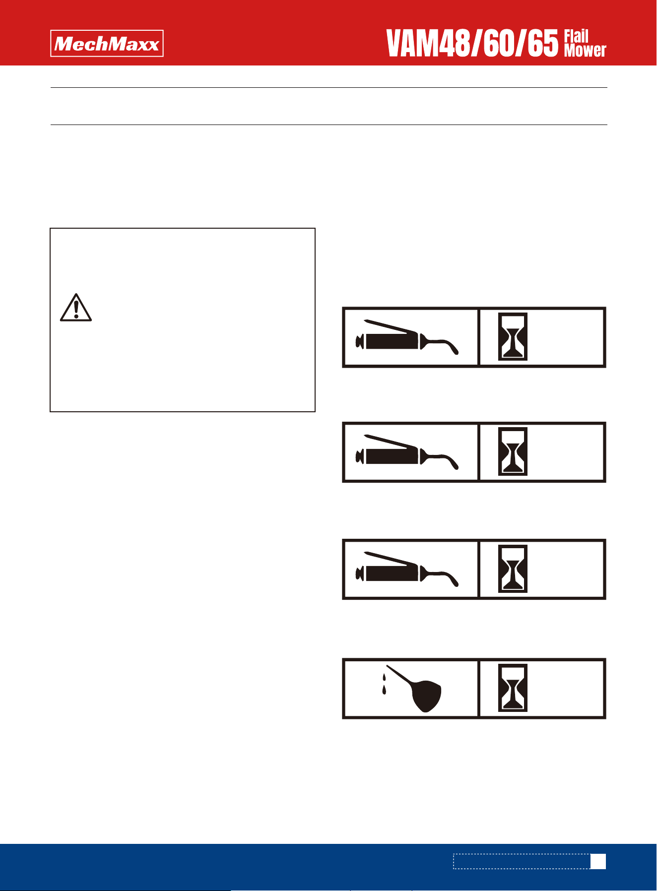
CHECK GEARBOX OIL
Type of Lubrication: SAE85W/90 Gear Lube
Check oil level in gearbox by removing the plug located on
the right hand side. Oil should be level with bottom of
plug hole. Add oil if necessary by removing top fill plug and
side plug. Add oil until it flows from side plug hole.
Do not overfill!

17
www.mechmaxx.com
TROUBLESHOOTING
TROUBLESHOOTING
Do not try to clean rear discharge area when mower is running. Bodily harm may
occur!
CAUTION
Solution
Problem
Belt slipping
Patches of uncutgrass
Excessive vibration
Knives scalping grass
Tractor loaded down
by mower
Uneven cut
Gearbox noisy
Unplug and clean mower deck.
Remove belt guard shields and clean sheaves.
Replace belt.
Mow at full throttle (540 PTO rpm), check PTO speed and tractor engine.
Shift transmission to a lower gear.
Tighten belts.
Check lubricant level.
Replace knives.
Replace drive belt.
Replace pulleys or align.
Remove belt guard shields & clean debris from belt area & sheaves.
Raise cutting height by adjusting roller.
Change mowing pattern.
Reduce speed turns.
Shift to a lower gear.
Level mower.
Replace missing knives.
Mow at full throttle (540 PTO rpm).
Shift to a lower gear.
Clean mower.
Replace missing knives.

18
www.mechmaxx.com
APPENDIX
APPENDIX
Bolt Diameter
SAE 2
N.m lb-ft N.m lb-ft N.m lb-ft
SAE 5 SAE 8
Bolt Torque
1/4"
5/16"
3/8"
7/16"
1/2"
9/16"
5/8"
3/4"
7/8"
8
13
27
41
61
95
128
225
230
6
10
20
30
45
60
95
165
170
12
25
45
72
110
155
215
390
570
9
19
33
53
80
115
160
290
420
17
36
63
100
155
200
305
540
880
12
27
45
75
115
165
220
400
650
The tables shown below give correct torque values for various bolts and cap screws. Tighten all bolts to the torques spec-
ified unless otherwise noted. Check tightness of bolts periodically, using bolt torque chart as a guide. Replace hardware
with the same strength bolt.
Bolt Torque
ENGLISH TORQUE SPECIFICATIONS

Bolt Diameter
8.8
N.m lb-ft N.m lb-ft
10.9
Bolt Torque
M3
M4
M5
M6
M8
M10
M12
M14
M16
M20
M24
M30
M36
0.5
3
6
10
25
50
90
140
225
435
750
1495
2600
0.4
2.2
4
7
18
37
66
103
166
321
553
1103
1917
1.8
4.5
9
15
35
70
125
200
310
610
1050
2100
3675
1.3
3.3
7
11
26
52
92
148
229
450
744
1550
2710
Torque figures indicated above are valid for non-greased or non-oiled threads and heads otherwise specified. Therefore,
do not grease or oil bolts or cap screws unless otherwise specified in this manual. When using locking elements, increase
torque values by 5%.
METRIC TORQUE SPECIFICATIONS
19
www.mechmaxx.com
APPENDIX

WARRANTY
Mechmaxx warrants to the original purchaser that this product will be free from defects in material and workmanship
beginning on the date of purchase by the end user according to the following schedule when used as intended and under
normal service and conditions for personal use. Overall Unit and Drive line: One year Parts and Labor Gearbox: One year on
all components. Blades and Belts: Considered wear items. This warranty covers the replacement of any defective part
by MechMaxx and the installation of that part by an authorized dealer. It does not cover common wear items, including
blades, belts, and tines. MechMaxx reserves the right to inspect any part claimed to be defective before issuing a replace-
ment. MechMaxx reserves the right to inspect any equipment or parts which are claimed to have been defective in materi-
al or workmanship. This warranty does not apply to any part or product which in MechMaxx's judgment shall have been
misused or damaged by accident or lack of normal maintenance or care, or which has been repaired or altered in a way
which adversely affects its performance or reliability, or which has been used for a purpose for which the product not
designed. Misuse also specifically includes failure to properly maintain oil levels, grease points, and drive line shafts.
Claims under this warranty must be made to the dealer which originally sold the product and all warranty adjustments
must be made through such dealer. MechMaxx reserves the right to make changes in materials or design of the product
at any time without notices. This warranty shall not be interpreted to render MechMaxx liable for damages of any kind,
direct, consequential, or contingent to property. Furthermore, MechMaxx shall not be liable for damages resulting from
any cause beyond its reasonable control. This warranty does not extend to loss of crops, any expense or loss for labor,
supplies, rental machinery or for any other reason. No other warranty of any kind whatsoever, express or implied, is made
with respect to this sale; and all implied warranties of merchantability and fitness for a particular purpose which exceed
the obligations set forth in this written warranty are hereby disclaimed and excluded from this sale.
20
www.mechmaxx.com
WARRANTY
21
www.mechmaxx.com
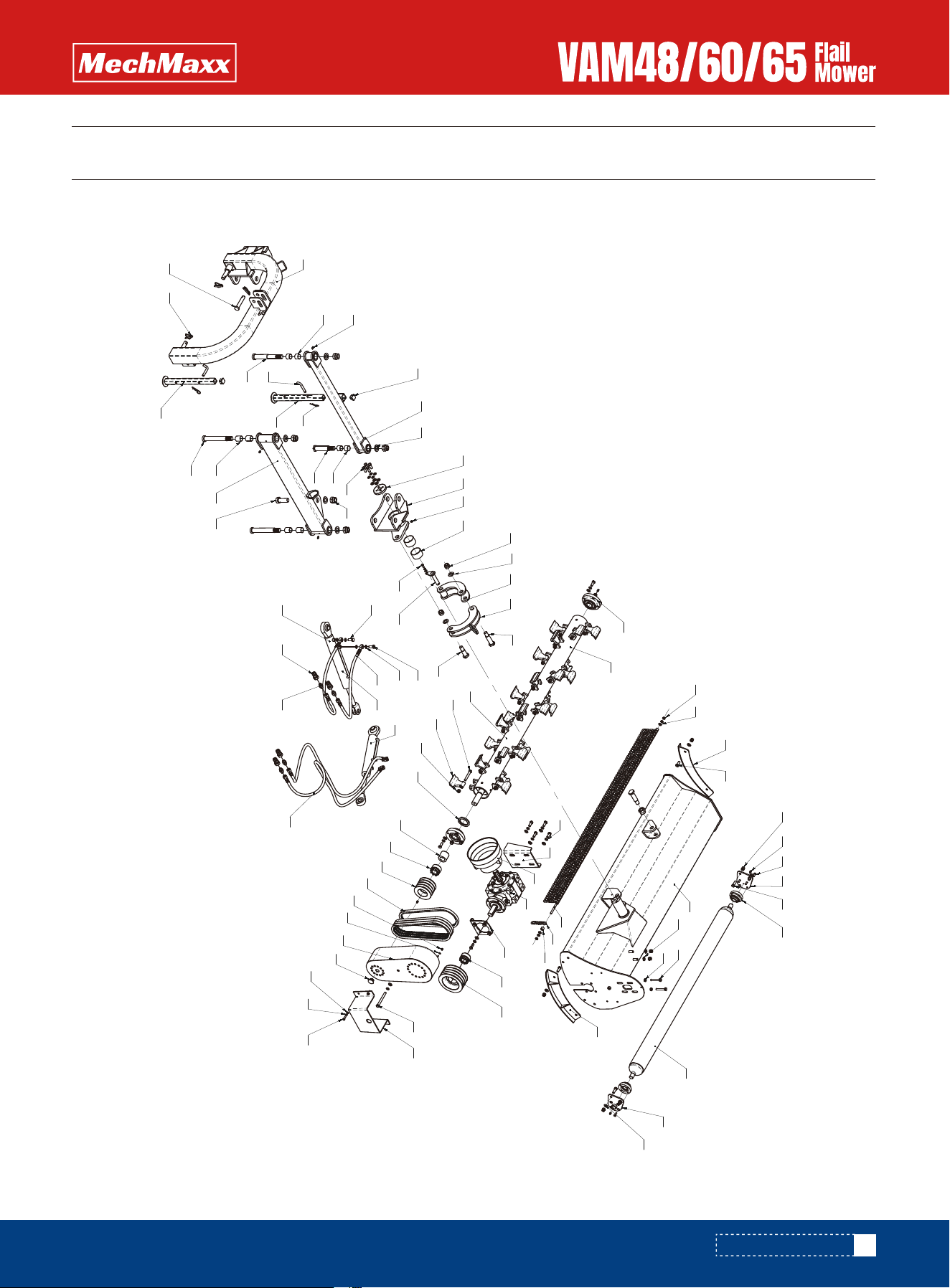
PARTS ILLUSTRATION
PARTS ILLUSTRATION
1 2
3
4
5
6
7
8
9
10
9
11
12
13 14
74
22
23
24
25
26
27
28
29
30
32
32-2
32-3
32-4
33
34
35
36
37
38
39
40
41
42 43
44
45
46
47
48
49
50
5152
5354
55
56
57
58
59
60
61
54
59
62
63
64
65
66
67
68 69
21
70
71 72
62
73
31
14
73-1
73-2
73-3 73-4
73-8 73-7
73-5
73-6
73-9
32-1
17
18
19
15
16

22
www.mechmaxx.com
VAM FLAIL MOWER PARTS LIST
VAM FLAIL MOWER PARTS LIST
No. PART NUMBER DESCRIPTION QTY
1
2
3
4
5
6
7
8
9
10
11
12
13
14
15
16
17
18
19
B-G00889A-12
B-J07940A-8*1A
B-G00070C-8*25
AGL165.19
B-G057830-12*35
EFGC175.19B
AGL125.21
AGL145.21
AGL165.21
AGL165.20
B-G00097A-12
AGL125.13
AGL145.13
AGL165.13
B-G057830-12*70
GB/T6172.1
AGL165.15
B-G057830-12*30
B-G06172A-10
B-G00097A-10
LM180.15
AGL165.30
AGL125.25
AGL145.25
AGL165.25
Nut M12
Oil cup M8*1-304
Bolt M8*25
Roller hanging plate welding weldment (R)
Bolt M12*35
UC205 bearing assembly
Roller weldment
Roller hanging plate welding weldment (L)
Plain washer 12
Hood welding assembly
Bolt M12*70
Nut M12
Sliding plate welding assembly (L)
Bolt M12*30
Nut M10
Plain washer 10
Spacer sleeve
chain
Barrier hanging rod
8
4
8
1
2
2
1
1
1
1
29
1
1
1
2
2
1
24
4
21
57
66
76
56
65
75
1
1
1

23
www.mechmaxx.com
VAM FLAIL MOWER PARTS LIST
No. PART NUMBER DESCRIPTION QTY
21
22
23
24
25
26
27
28
29
30
30
31
32
32-1
32-2
32-3
32-4
33
34
35
B-G00889A-24
AGLJA125.25
B-G00889A-20
B-G000930-12
AGL165.16
FM150.120
W-01-T101L
AGL165.17
B-J7934Z3-33*60
EFGC155.31
EFGC175.31
EFGC175.25A
AGL125.22A
AGL145.22A
AGL165.22A
AGL125.22
AGL145.22
AGL165.22
B-G057820-12*80
AGL165.39
B-G00889A-12
B-G13871A-FB55*80*8
EFGC155.26
EFGC175.26
B-J7934Z3-35*60
Locking nut M24
AGLJA125.25
Locking nut M20
Spring washer 12
Gearbox assembly
Drive shaft cover
Gearbox (50HP)
Gearbox adjustment plate welding assembly
Swellable sleeve Z3-33*60
Big belt ptlley
Reverse installation of bearing UCU207
Knife shaft component
Blade shaft welding assembly
Bolt M12*80
Hammers(400g)
Nut M12
Oil seal FB55*80*8
Oil-sealing sleeve
Swellable sleeve Z3-35*60
5
2
3
21
1
1
1
1
1
1
1
2
1
1
1
1
1
1
20
24
28
20
24
28
20
24
28
1
1
1
1

24
www.mechmaxx.com
VAM FLAIL MOWER PARTS LIST
No. PART NUMBER DESCRIPTION QTY
36
37
38
39
40
41
42
43
44
45
46
47
48
49
50
51
52
53
54
55
56
57
58
59
60
61
62
EFGC155.27
EFGC175.27
GB/T12732
B-G00889A-6
B-G00097A-6
AGL145.18SDMH
AGL165.18SDMH
W-08-Y25
B-G057820-12*110
B-G057820-12*130
AGL165.24A
AGL165.24B
B-G00097A-8
B-G000930-8
B-G057830-8*25
AGLJA125.10
AGLJA125.11
B-G057820-24*100
B-G057830-24*80
AGL165.23
B-G057830-8*20
W-06-SF-2-6340
B-J07940A-8*1A
AGL165COS.8A
AGL165.9
B-G00097A-24
AGL165.4
W-06-SF-2-3025
AGL165.6
W-08-F40
AGL165.5
1
1
3
4
1
1
1
1
1
1
1
1
1
5
5
4
1
1
1
1
1
1
2
5
1
1
6
1
4
1
2
2
Small belt ptlley
Tooth shaped V-belt AV17 * 991
Nut M6
Washer 6
Pulley cover weldment
Circular rubber cover with a diameter of 25
Bolt M12*110
Bolt M12*130
Belt pulley cover guard
Plain washer 8
Spring washer 8
Bolt M8*25
Upper lunar plate welding assembly
Lower Moon Plate Weldment
Bolt M24*100
Bolt M24*80
Pin welding assembly
Bolt M8*20
Bushing SF-2-68 * 63 * 40
Straight-through oil filler cup M8 * 1
Tilting and welding assembly
round clamp
Plain washer 24
Small rotating arm welding assembly
Bushing SF-2-34 * 30 * 25
Short pin
Square rubber cover □ 40
Leg welding assembly

No. PART NUMBER DESCRIPTION QTY
63
64
65
66
67
68
69
70
71
72
73
73-1
73-2
73-3
73-4
73-5
73-6
73-7
73-8
73-9
74
EFGC125.110
EFGC175.37
AGL165.2B
W-06-SF-2-3040
AGL165.2
AGLJA125.3
B-G057830-24*70
AGL165COS.1A
EFGC175.33
B-G043290-10
AGL165.26
AGL165COS.26B.3
B-J009820-12
AGL165.26-2
AGL165.7A
AGL165.12A
AGL165.26-1
W-05-GE10LR1/2ED
B-G058620-L-G1/2
B-J009990-12*1.25*30
AGL165.14
2
2
1
4
2
1
1
1
1
3
1
2
8
2
1
1
2
4
4
2
1
R pin 3.2
Supporting pin
Long pin 2
Bushing SF-2-34 * 30 * 40
Long pin
Big rotating arm welding assembly
Bolt M24*70
Hanging weldment
Upper suspension pin
Locking pin 10
Hydraulic Components
Hinge bolt with throttle hole
Combination washer 12
Swing cylinder oil pipe
Swing cylinder
Tilting cylinder
Tilting cylinder oil pipe
End straight connector G1/2-M16 * 1.5
Quick change male connector G1/2
Hinge bolt M12 * 1.25 * 30
Sliding plate welding assembly (R)
25
www.mechmaxx.com
VAM FLAIL MOWER PARTS LIST