DANGER · FLAMMABLE GAS UNDER PRESSURE.
LEAKING LP-GAS MAY CAUSE A FIRE OR EXPLOSION IF IGNITED
CAUSING SERIOUS BODILY INJURY OR DEATH.
CONTACT LP GAS SUPPLIER FOR REPAIRS, OR DISPOSAL OF THIS
CYLINDER OR UNUSED LP-GAS.
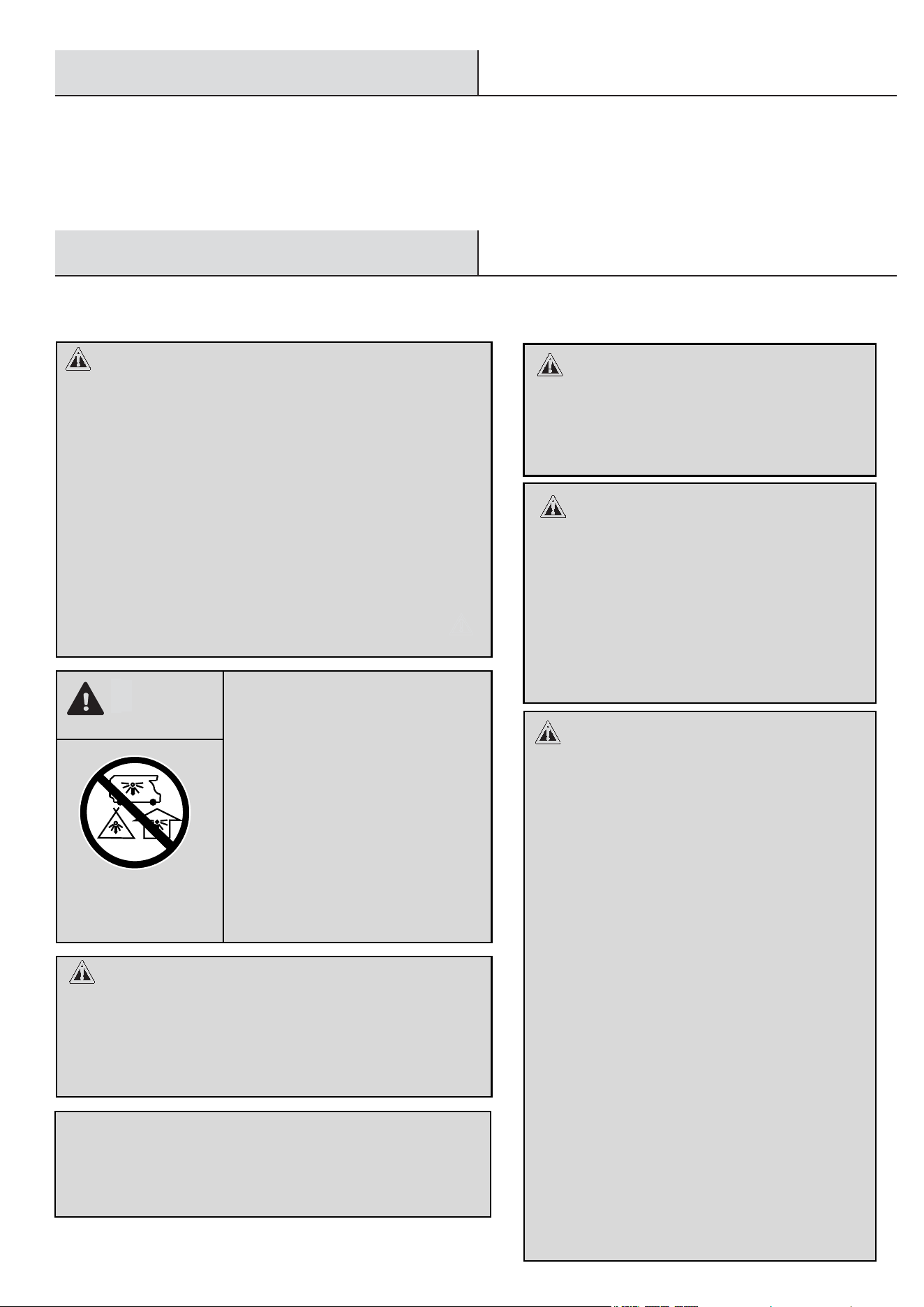
WARNING · FOR OUTDOOR USE ONLY.*
DO NOT USE OR STORE CYLINDER IN A BUILDING,
GARAGE OR ENCLOSED AREA.
WARNING:
Know the odor of LP-gas. If you hear, see or smell
leaking LP-gas, immediately get everyone away
from the cylinder and call the Fire Department.
Do not attempt repairs.
Caution your LP-gas supplier to:
Be certain cylinder is purged of trapped air prior
to first filling.
Be certain not to over fill the cylinder.
Be certain cylinder requalification date is checked.
Do not use, store or transport cylinder where it would
DO NOT REMOVE, DEFACE, OR OBLITERATE THIS LABEL
*EXCEPT AS AUTHORIZED BY ANSI/NFPA 58.
DANGER. Do not store a spare LP cylinder under or near a barbecue grill, or other
heat sources. NEVER fill an LP cylinder beyond 80% full: a fire causing death or
serious injury may occour.
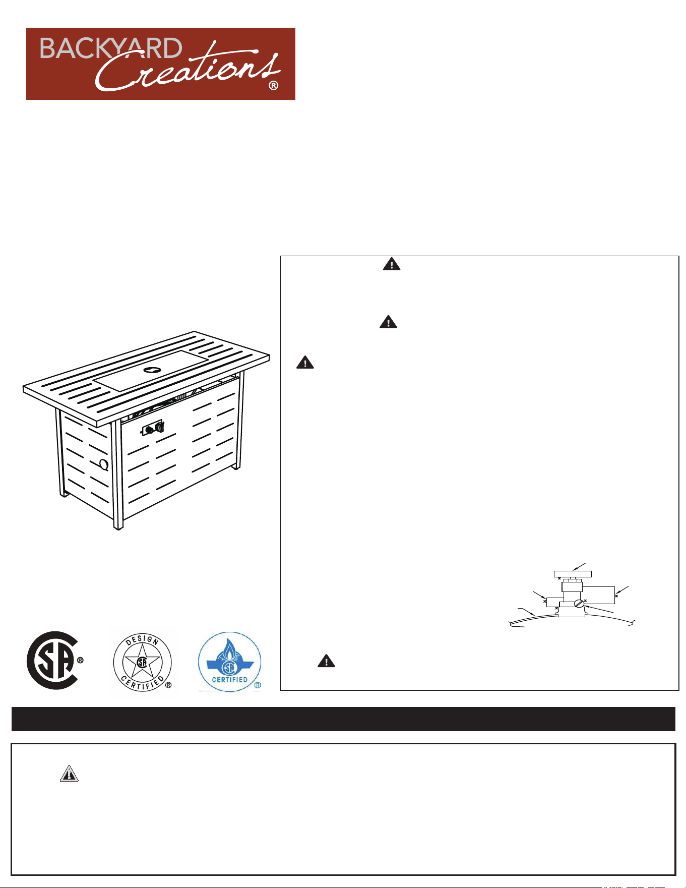
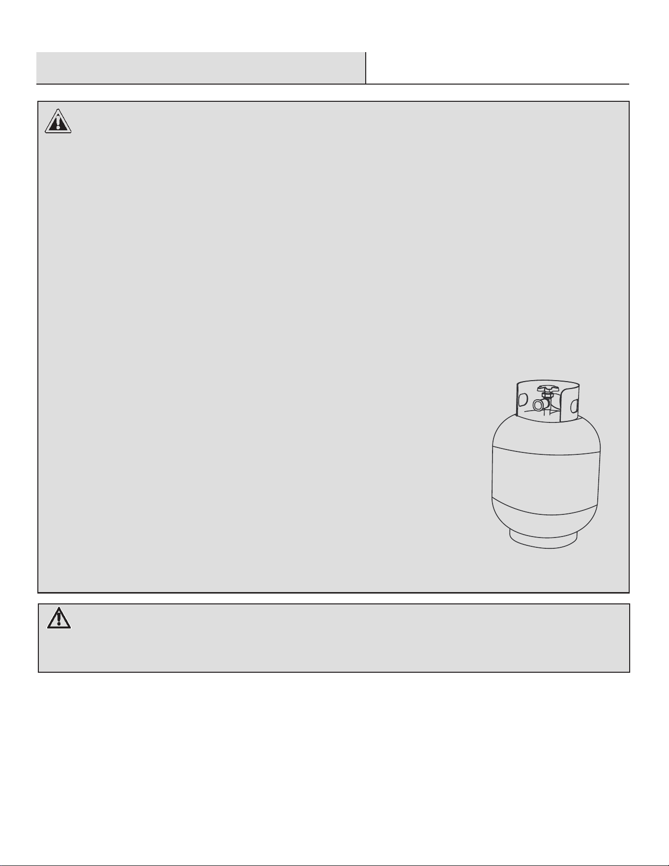
WHEN CONNECTING FOR USE:
Use only in compliance with appliable codes.
Read and follow manufacturer’s instructions.
Consult manufacturer’s instructions
concerning the cylinder connection provided
with your appliance.
Be sure regulator vent is not pointing up.
Turn off all valves on the appliance.
Do not check for gas leaks with a match or
open flame. Apply soapy water at areas
marked ”X”. Open cylinder valve. If bubble
appears, close valve and have LP-gas
service person make needed repairs. Also,
check appliance valves and connections to
make sure they do not leak before lighting
appliance.
Light appliance(s) following manufacturer’s
instructions.
When appliance is not is use, keep the
cylinder valve closed.
X
X
X
X
X
Cylinder
Pressure relief valve
Cylinder valve hand wheel
Point of connection
Liquid level indicator
(optional)
·
·
·
·
LP-gas is heavier than air and may settle in low
places when dissipating.
·
Contact with the liquid contents of cylinder will
cause freeze burns to the skin.
Do not allow children to tamper or play with cylinder.
·
When not connected for use, keep cylinder valve
turned off. Self contained appliances shall be limited to
a cylinder of 20 lb capacity or less.
·
be exposed to high temperatures. Relief valve may
open allowing a large amount of flammable gas to
escape.
·
When transporting, keep cylinder secured in
an upright position with cylinder valve turned off.
·
·
·
·
·
·
·
·
Please keep this instruction manual for future reference
Questions, problems, missing parts? Before returning to the store, email Yayi at
WARNING:
READ INSTRUCTION MANUAL BEFORE ATTEMPTING TO ASSEMBLE
OR OPERATE THIS PRODUCT.
C
US
R
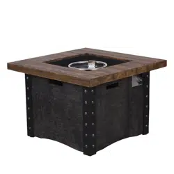
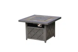
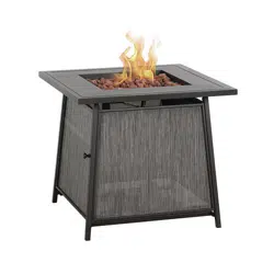
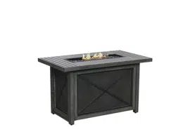
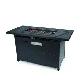
Item # 2595305
45" ACADIA GAS FIRE TABLE
Assembly Instructions
DANGER:
• Shut off gas to the appliance.
• Extinguish any open flame.
• If odor continues, leave the area immediately
After leaving the area, call your gas supplier
or fire department.
WARNING: For Outdoor Use Only!
Do not store or use gasoline, or other flammable
vapors and liquids, in the
vicinity of this or any
An LP-cylinder not connected for
shall not be stored in the vicinity of this or
any other appliance.
2
FIRE OR EXPLOSION HAZARD
If you smell gas:
•
Failure to follow these instructions could result in
fire or explosion, which could cause property
damage, personal injury, or death.
Safety Information
DANGER
CARBON MONOXIDE HAZARD
This appliance can produce
carbon monoxide which has no
odor.
Using it in an enclosed space
can kill you.
Never use this appliance in an
enclosed space such as a
camper, tent, car or home.
Installation and service must be
performed by a qualified installer,
service agency, or the gas supplier
INSTALLER: leave this manual with the appliance.
CONSUMER: Retain this manual for future
reference.
WARNING:
WARNING:
FOR YOUR SAFETY:
If the information in this manual is not
followed
exactly, a fire or explosion may
result causing property damage,
personal injury or loss of life.
WHAT TO DO IF YOU SMELL GAS:
Do not try lighting any appliance.
Do not touch any electrical switch; do
NOT use any phone in your building.
Immediately call your gas supplier from
a neighbor’s phone.
Follow the gas supplier’s instructions.
If you cannot reach your gas supplier.
Call the fire department.
Installation and service must be
performed by a qualified installer, service
agency or gas supplier. Save these
instructions for future reference. If you
are assembling this unit for someone
else, give this manual to him or her to
read and save for future reference.
other appliance.
use
Read before use. This appliance must be installed in accordance with such
regulations as are enforced.
Safety Information..
.........................................................2-4
Warranty.........................................................................5
Pre-Assembly...……………………...…………………….
5
Operating Instructions .........................................12-14
Maintenance...........................................................15
Care and Cleaning ................................................15
Troubleshooting
....................................................16
Table of Contents
..………………...…………………….
6
Package Contents
Assembly..………………………………………....…7-11
Table of Contents ................................
..........................2
Service Parts
...........................
......................
17
WARNING:
Improper installation, adjustment,
alteration, service or maintenance can
cause property damage, personal injury
or loss of life.
Read the installation, operating, and
maintenance instructions thoroughly
before installing or servicing this
equipment.
3
Safety Information (continued)
.
WARNING:
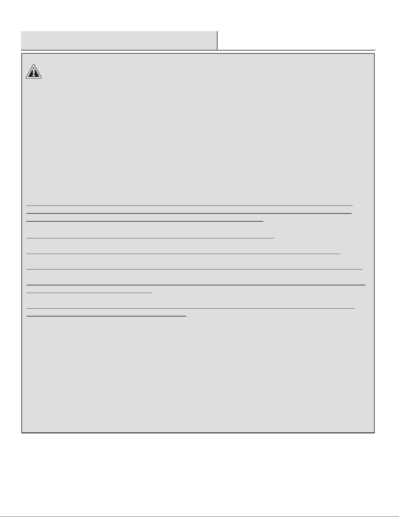
You must provide propane gas and propane cylinder. Use a standard 20 lb. propane cylinder only.
Use this heater only with a propane vapor withdrawal supply system. See Chapter 5 of the Standard for Storage and
Handling of Liquefied Petroleum Gas, ANS/NFPA 58. Your local library or fire department should have this book.
The pressure regulator and hose assembly supplied with the appliance must be used.
The installation must conform with local codes, or in absence of local codes, with National Fuel Gas Code, ANSI Z223.1.
A dented, rusted, or damaged propane cylinder may be hazardous and should be checked by your cylinder supplier.
Never
use a propane cylinder with a damaged valve connection.
The LP-gas supply cylinder must be constructed and marked in accordance with the U.S. Department of Transportation
(D.O.T) Specifications for LP-Gas Cylinders, or the standard for Cylinders, Spheres and Tubes for Transportation of
Dangerous Good and Commission, CAN/CSA-B339, as applicable.
The LP-gas supply cylinder must be provided with a cylinder connection device compatible with the connection for the
appliance.
The cylinder used must include a collar to protect the cylinder valve.
The LP-gas supply cylinder must be provided with a listed overfill protection device (OPD).
Do not store a spare LP gas cylinder under or near this appliance.
Never fill the cylinder beyond 80 percent full.
For appliances designed to use a CGA No. 791IQCC connection.
Place the dust cap on the cylinder valve outlet whenever the cylinder is not in use.
Note: Gas supply pressure: 25 PSI to 250 PSI.
Standard 20 lb tank
WARNING: FUELS USED IN LIQUID PROPANE GAS APPLIANCES, AND THE PRODUCTS OF
COMBUSTION OF SUCH FUELS, CAN EXPOSE YOU TO CHEMICALS INCLUDING BENZENE, WHICH IS
KNOWN TO THE STATE OF CALIFORNIA TO CAUSE CANCER AND CAUSE BIRTH DEFECTS OR OTHER
REPRODUCTIVE HARM. For more information go to: www.P65Warnings.ca.gov.
4
Safety Information (continued)
WARNING:
Solid fuels shall not be burned in this appliance.
The installation must conform with local codes or, in the absence of local codes, ANSIZ223. 1/NFPA54, NFPA58 Natural
Gas and Propane Installation Code, CSA B149.1, or Propane Storage and Handling Code, B149.2.
Prior to use, check for damaged parts such as hoses, regulators, pilots, or burners.
Inspect the fuel supply connection for signs of leakage (including the hose for the LP models) before each use of the
appliance.
All leak tests should be done with a soapy solution. NEVER USE AN OPEN FLAME TO CHECK FOR LEAKS.
Children and adults should be alerted to the hazards of high surface temperatures and should stay away from the
appliance to avoid burns or clothing ignition. This appliance comes with a heat shield which is an important safety
component preventing contact with the fire bowl when adjusting the propane valve.
Young children should be carefully supervised when they are in the area of the heater.
Clothing or other flammable materials should be not be hung from the heater, or placed on or near the heater.
Any guard or other protective device removed for servicing the heater, must be replaced prior to operating the heater.
Installation and repair should be done by a qualified service person. The heater should be inspected before use and at
least annually by a qualified service person.
More frequent cleaning may be required as necessary. It is imperative that the control compartment, burners, and
circulating air passageways of the heater be kept clean.
Keep the appliance area clear and free from combustible materials, gasoline, and other flammable vapors and liquids.
DO NOT OBSTRUCT the combustion process or air ventilation flow.
Keep the ventilation opening(s) of the cylinder enclosure free and clear from debris.
The appliance should be used in a well-ventilated space and not in a building, garage or any other enclosed area.
An appliance may be installed within a shelter if the shelter meets one of the following conditions:
The shelter has walls on all sides, but with no overhead cover.
The shelter is within a partial enclosure which includes side walls. These side walls may be parallel, as in a breezeway,
or at right angles to each other.
This appliace must be isolated from the gas supply piping system by closing its individual manual shutoff valve during
any pressure testing of the gas supply piping system at test pressures equal to or less than 1/2 psi (3.5 kPa).
Max. gas supply 6791.3 in wc (1725 kPa). Manifold pressure 11 in wc (2.74 kPa).
Warranty
Pre-Assembly
NOTE:
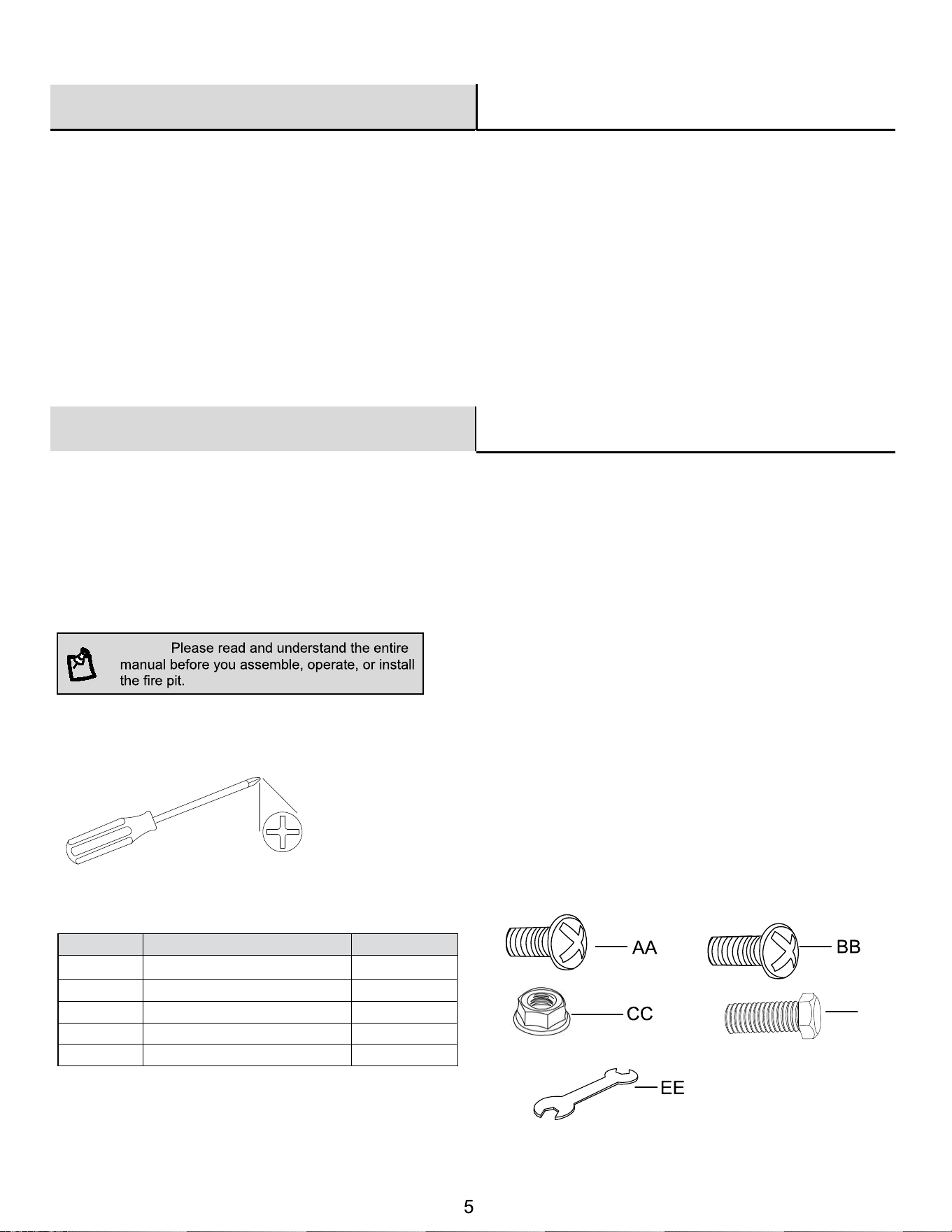
HARDWARE INCLUDED
Part Description Quantity
M6 Nut
8
Wrench
Part
DD
TOOLS REQUIRED
Phillips
screwdriver
(NOT INCLUDED)
25
2
1
1
1
YEAR LIMITED WARRANTY
WHAT IS NOT COVERED
It remains the
customer’s responsibility for freight and packaging charges to and from our service center. This warranty
does not cover commercial use, acts of nature, fire, freezing and abusive use. In addition, purchased parts are not
covered under this warranty. We reserve the right to make substitutions with similar merchandise, if the model in
question is no longer in production.
Contact the Customer Service Team at [email protected].
• We warrant the metal frame and burner to be free of manufacturing defects to the original purchaser for one year.
• Proof of purchase (dated register receipt) is required for warranty claims.
PLANNING ASSEMBLY
Carefully remove all pieces from the carton and make sure that you have all parts (refer to the hardware and package contents list).
If you are missing parts, please contact the customer service team at [email protected] for further assistance.
YOUR OWNER’S MANUAL
Keep and store this Owner’s Manual for future reference. It contains important instructions and procedures for safety and
maintenance.
M6 x 20 mm Bolt
M6 x 10 mm Bolt
M6 x 12 mm Bolt
AA
BB
CC
DD
EE
6
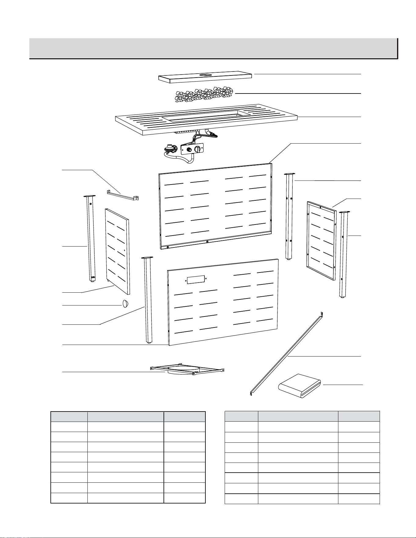
Package Contents
Part
Quantity
A
1
B
1
C
Back Leg C
1
D
1
E
1
Description
Front Leg A
Front Leg B
Back Leg D
Metal Lid
F
1
Lava Rock
G
Table Top with Burner
1
B
C
D
A
E
F
G
H
I
J
K
L
M
N
H
Back Panel
1
O
P
Part
Quantity
I
1
J
1
K
1
L
1
Description
Door Panel
Side Panel with Window
Gas Tank Support
Connection Bar 1
M
Door Knob
1
N
1
Side Panel
1
Connection Bar 2
O
1
Protective Cover
P
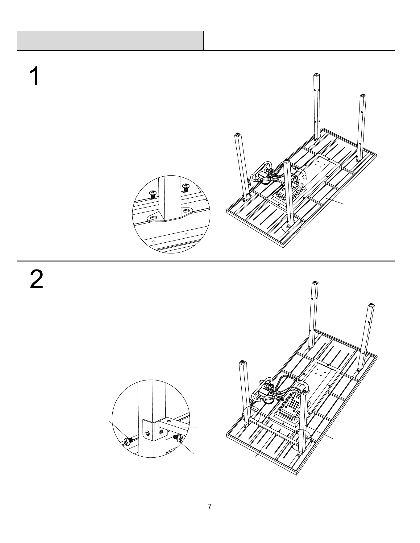
Assembling the connection bar 2
□
□
Assembly
Assembling the legs
□
□
A
B
C
D
G
AA
A
B
C
D
O
BB
BB
O
Attach Connection Bar 2 (O) to the Legs (A,B)
using four (4) M6 x 12mm bolts (BB).
Do not tighten the bolts at this step.
Place Table Top with Burner (G) upside down on a
flat, protected surface.
Attach the Legs (A,B,C,D) to the Table Top with
Burner(G)using eight (8) M6 x 10 mm bolts (AA).
Do not tighten the bolts at this step.
3
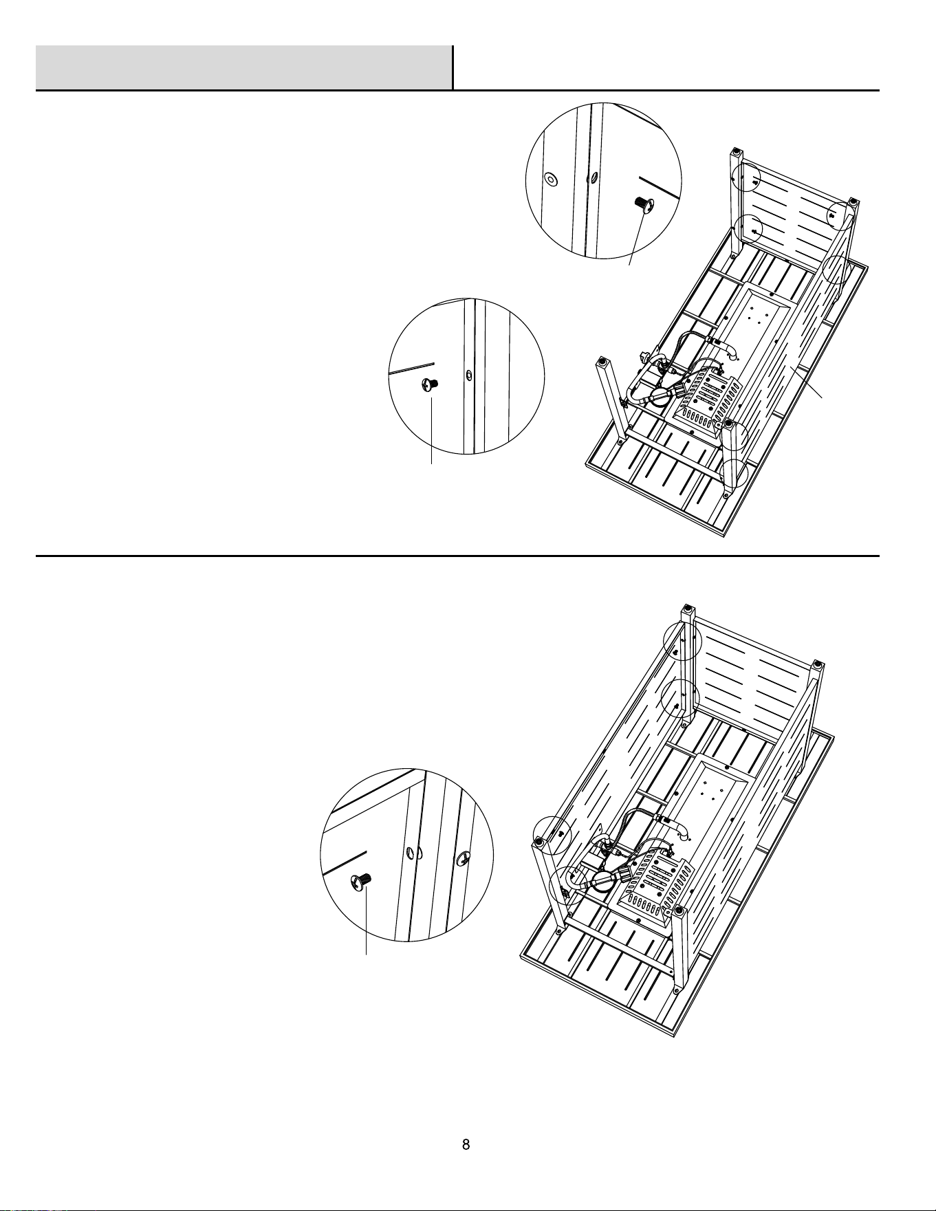
Assembling the panels
□ Attach the Back Panel (H) to Legs (C,D) using
four (4) M6 x12mm bolts (BB), attach Side
Panel (I) to Legs (A,D) using four (4) M6 x 12mm
bolts (BB).
□ Do not tighten the bolts at this step.
4
Assembling the side panel with window
□ Attach Side Panel with Window (K) to Legs
(B,C) using four (4) M6 x 12mm bolts (BB).
□ Do not tighten the bolts at this step.
Assembly (continued)
B
C
D
H
I
BB
BB
BB
K
B
C
9
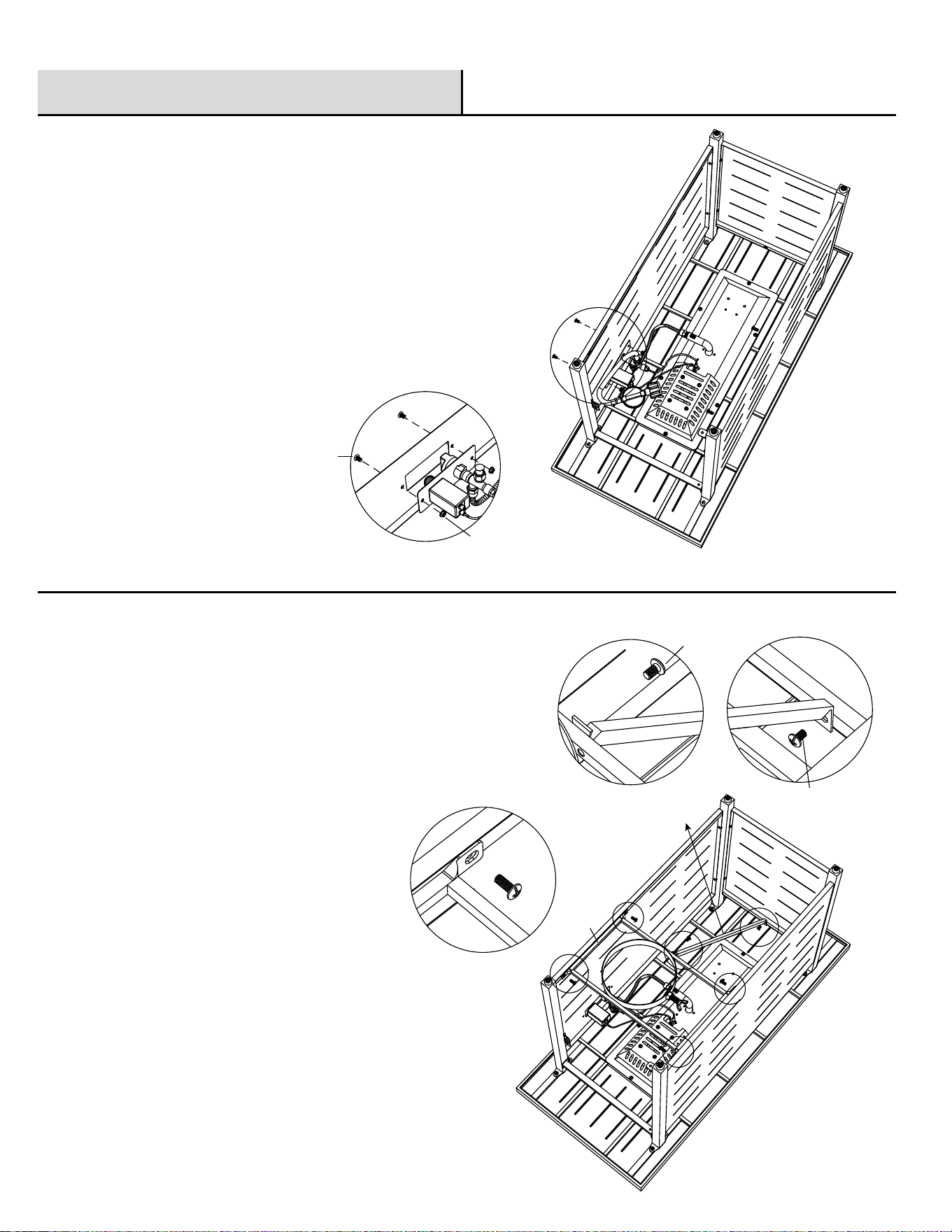
5
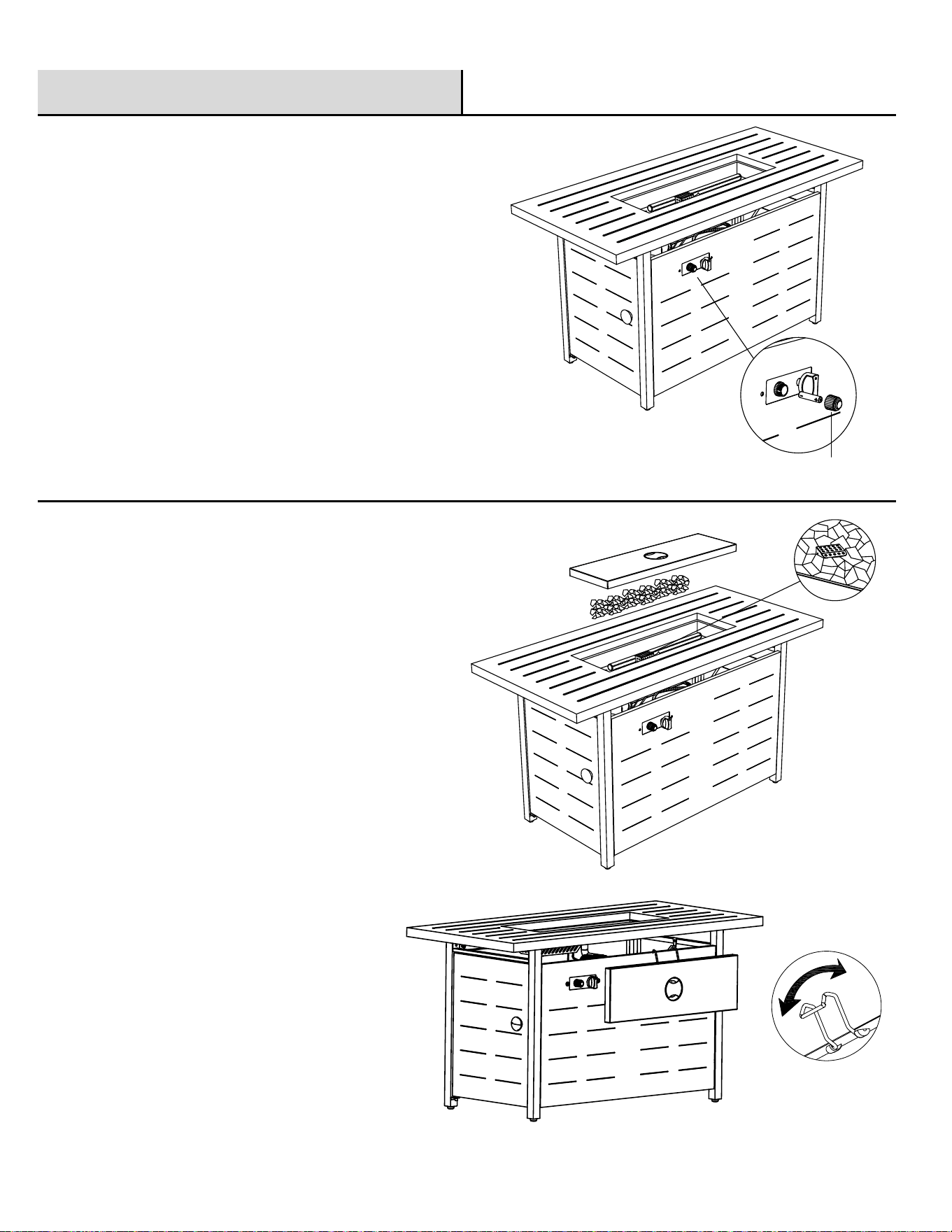
Assembling the control panel
6
Assembling the gas tank support
□
□
Attach Gas Tank Support (L) to Side Panel (I) and Side
Panel with Window (K) using four (4) M6 x 12mm
bolts (BB).
Attach Connection Bar 1 (M) to Gas Tank Support (L) and
Back Panel (H) using two (2) M6 x 12mm bolts (BB).
Assembly (continued)
BB
CC
K
L
M
H
a x4
a
a
a
a
b
b
c
c
BB
BB
BB
□ Do not tighten the bolts at this step.
□ Attach the Control Panel to the Side Panel with
Window (K) using two (2) M6 x 12 mm Bolts (BB)
and two (2) M6 nut (CC).
□ Tighten the bolts with a Phillips screwdriver.
10
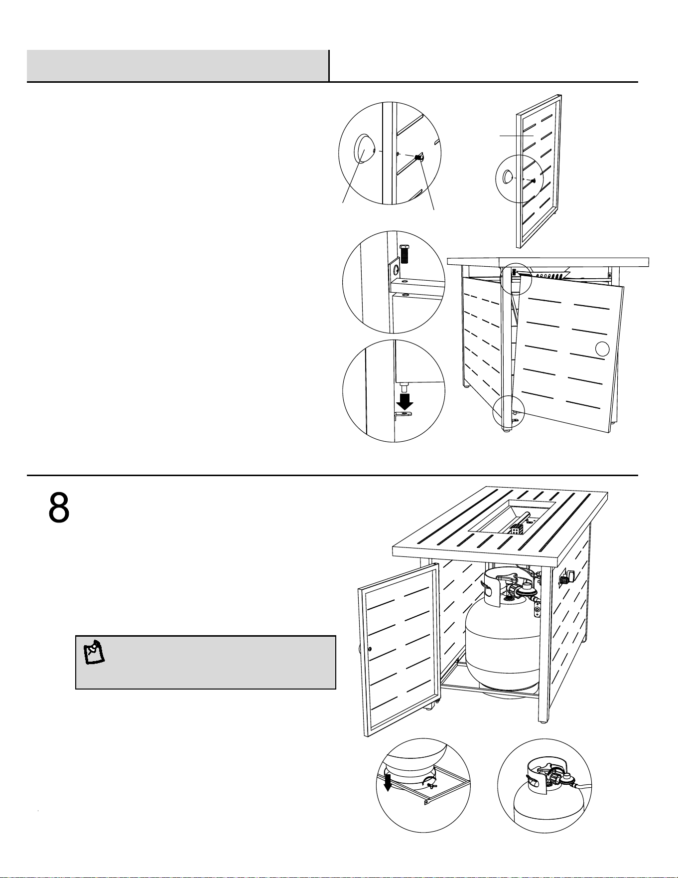
Assemblng the cylinder
□ Put the cylnder into the Gas Tank Support (L), and
secure the cylinder by tightening the screw in the
gas tank suppport. Connect the hose and regulator
to the cylinder.
Assembly (continued)
Assembling the door
□
Attach Door Knob (N) to Door Panel (J) using
one (1) M6*12 mm bolt (BB).
Please fully tighten all bolts at this step.
DD
NOTE: The propane cylinder is sold separately.
Use a standard 20 lb. propane cylinder only.
7
N
BB
J
A
□
□
Orient the unit so that Table Top with Burner (G)
is facing up.
Attach Door Panel (J) to Front Leg A (A) using
one (1) M6*20 mm bolt (DD), tighten the bolt
using Wrench (EE).
11
9
10
Installing the AAA battery
Assembly (continued)
Place the lava rock
□
□
Open the igniter and place AAA battery (not
included) into the igniter. Then tighten
clockwise.
□
Put the Lava Rock (F) into the fire bowl. Ensure
lava rock is not placed on the ignition portion of
the burner.
Place the Metal Lid (E) over the top.
The Metal Lid (E) must be removed when the
burner is in operation.
The lid can be hung on the side of the panel
using the lid hanger.
Wait until the unit cools before placing the
cover (P.)
igniter cover
□
Operating
WARNING: Never use this appliance for other than the intended use. DO NOT use this appliance to prepare
food.
Initial Lighting: When lit for the first time, the appliance emits a slight odor. This is a normal temporary condition caused
by the “burn-in ” of internal paints and lubricants used i n the manufacturing process and does not occur again. Simply run
the main burner on high for approximately one-half hour.
WARNING:
Children and adults should be alerted to the hazards of high surface temperatures and should stay away from the
appliance to avoid burns or clothing ignition. The appliance comes with a heat shield which is an important safety
component preventing contact with the fire bowl when adjusting the propane valve.
Children should be carefully supervised when they are in the area of the appliance.
Clothing or other flammable materials should not be hung from the appliance, or placed on or near the appliance. The
area above the fire pit may be extremely hot. Direct contact with these surfaces should be avoided in order to prevent
burns or clothing ignition.
Any guard or protective device removed for servicing the appliance must be replaced prior to operating the appliance.
Installation and repair should be done by a qualified service person.
The appliance should be inspected before each use and at least annually by a qualified service person. It is imperative
that the control compartment, burners and circulating air passageways of the appliance be kept clean.
WARNING:
Never use the appliance while it is raining. Always turn the appliance off when raining.
Never use the appliance if the burner is damaged. Inspect the burner before each use. Ensure that no debris such as
leaves; grass or other objects have entered or are on the appliance. If the burner is damaged it must be replaced prior
to using this appliance with a replacement burner specified by your dealer.
Inspect the hose assembly before each use. If there is evidence of excessive abrasion or wear, or if the hose is
damaged it must be replaced prior to using the appliance with a replacement hose assembly specified by your dealer.
WARNING: Any modification to the appliance may compromise the safety of this appliance.
Special concern is as follows:
Do not bypass the thermocouple safety.
Do not operate the appliance if any parts have been under water. Immediately call a qualified service technician to
inspect the appliance and replace any part of the control system, and any gas control, which has been under water.
12
13
Operating (continued)
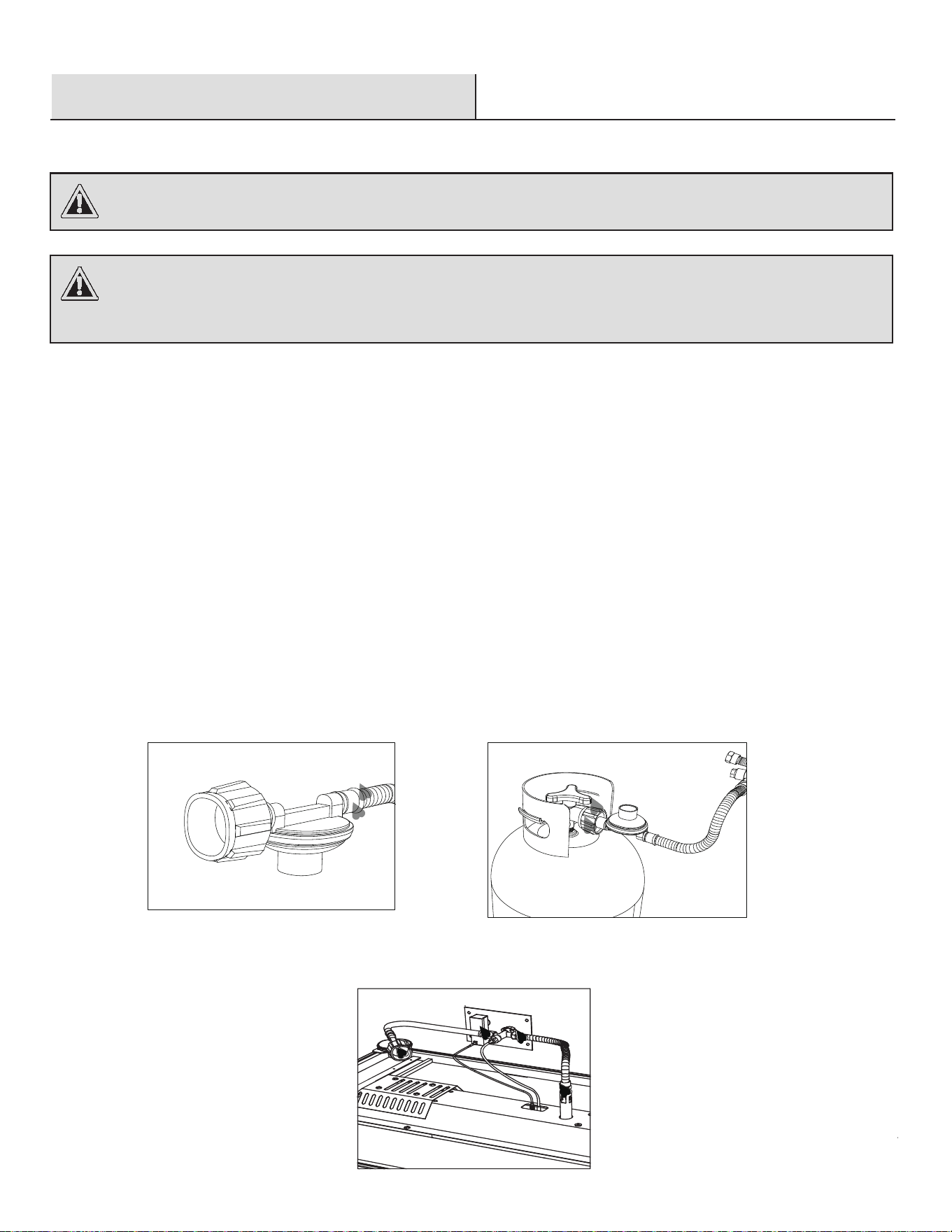
WARNING: A leak test must be performed annually or if a part of the gas system is replaced.
LEAK TESTING OPERATION
WARNING: Never use an open flame to check for gas leaks. Be certain no sparks or open flames are in the area
while you check for leaks. Sparks or open flames will result in a fire or explosion, damage to property, serious
bodily injury, or death.
LEAK TESTING:
1, Make 2-3 oz. of leak detection solution by mixing one part liquid dishwashing soap with three parts water.
2, Make sure all fire pit and light valves are OFF.
3, Apply several drops of solution where hose attaches to regulator.
4, Apply several drops of solution where regulator connects to cylinder.
5, Turn cylinder valve ON.
If bubbles appear at any connection, there is a leak.
1, Turn cylinder valve OFF.
2, If leak is at hose/regulator connection: tighten connection and perform another leak test. If bubbles continue appearing,
Please contact customer service at [email protected] for assistance.
3, If leak is at regulator/cylinder valve connection: disconnect, reconnect, and perform another leak test. If you continue
to see bubbles after several attempts, cylinder valve is defective, and contact customer service at
[email protected] for assistance.
If NO bubbles appear at any connection, the connections are secure.
NOTE: Whenever gas connections are loosened or removed, you must perform a complete leak test .
Hose/Regulator
Connection
Regulator/Cylinder
Connection
Operating (continued)
CAUTION: Keep the outdoor gas appliance area clear and free from combustible materials, gasoline and
other flammable vapors and liquids.
LIGHTING INSTRUCTIONS
CAUTION: Do NOT obstruct the flow of combustion and ventilation air.
CAUTION: Check and clean burner/venturi tubes for insects and insect nests. A clogged tube can lead to
a fire.
Shut Down
1. To extinguish burner depress control knob and turn it clockwise to “OFF”
2. Turn cylinder valve clockwise to “OFF” and disconnect regulator when fire pit is not in use.
14
WARNING: Surface of the fire pit can remain extremely hot for a period after use. Allow 45 minutes
to cool
before repeating the procedure.
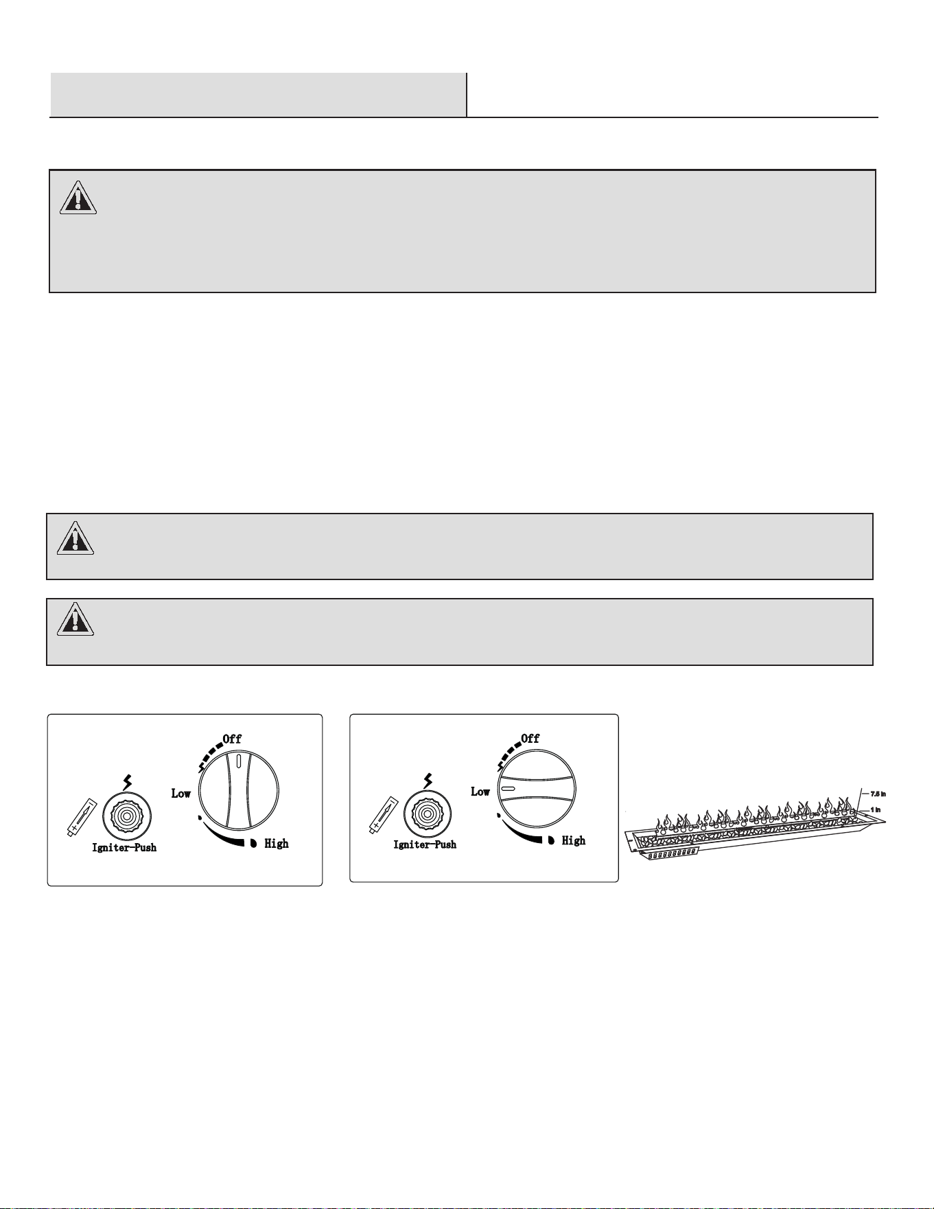
1. Make sure all labels, packaging and protective films have been removed from the outdoor fire pit.
2. Control knob must be in the “OFF” position (Figure 1).
3. Full open LP cylinder valve.
4. Press and hold electronic igniter button.
5. Press the control knob, turn counterclockwise to “Low” position, press and hold. When the burner lights, release the
electronic igniter button (Figure 2).
6. Continue to depress the gas control knob for 30 seconds and then release. If the flame goes out, repeat the procedure.
7. Adjust the flame to the desired height with the gas control knob. Visually check the burner flames as pictured below
(Figure 3).
8. If the burner will not light with the electronic igniter, hold a lit long match or lit long butane lighter to the ignition area of
the burner and continue with step 5.
Figure 3
WARNING: If the burner does not light within 10 seconds,turn the valve off and wait 5 minutes for gas
to dissipate before repeating the procedure.
Figure 1
Figure 2
15
Maintenance
Storage between uses:
Storage during periods of extended inactivity or wh
en transporting:
□
□
□
□
Care and Cleaning
NOTE: Wait until heater is cool before covering.
NOTE: Wait until heater is cool before covering.
Whenever conduct hose/regulator inspection, pull out the door using handle on the door panel to gain access.
Keep exterior surface clean.
Use warm soapy water for cleaning. Never use flammable or corrosive cleaning agents.
While washing your unit, be sure to keep the area around the burner dry at all times. If the gas control is exposed to
water, do NOT try to use it. It must be replaced.
Keep the appliance area free and clean from combustible materials, gasoline or other flammable vapors and liquids.
At least once a year, the unit should be inspected for the presence of spiders, spider webs or other insects.
Air flow must be unobstructed. Keep controls, burner, and circulating air passageways clean. Signs of possible
blockage include:
Gas odor with extreme yellow tipping of flame.
Heater does NOT reach the desired temperature.
Heat glow is excessively uneven.
Heat makes popping noises.
Spider and insects can nest in burner or orifices. This dangerous condition can damage heater and render it unsafe for
use. Clean burner holes by using a heavy-duty pipe cleaner. Compressed air may help clear away smaller particles.
Carbon deposits may create a fire hazard. Clean reflector, thermocouple, and emitter screen with a dry cloth if any
carbon deposits develop.
The burner is made from stainless steel, but extreme heat and a corrosive environment can cause surface corrosion to
occur. This can be removed with a brass wire brush. Inspect the burner at least annually for cracks, insect nests,
excessive corrosion or any other damage. If the burner is damaged, it must be replaced with a burner specified by the
manufacturer before the appliance is put into operation.
□ Turn the control knob to “OFF” position.
□ Disconnect LP source.
□ Store heater upright in an area sheltered from direct contact with inclement weather (such as rain, sleet, hail, snow, dust
and debris).
□ If desired, cover heater to protect exterior surfaces and to help prevent build up in air passages.
To enjoy years of outstanding performance from your heater, make sure you perform the following
maintenance activities on a regular basis:
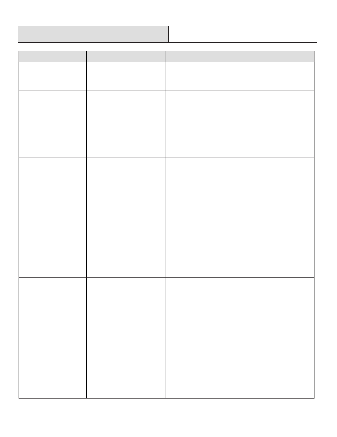
Troubleshooting
PROBLEM
PROBLEM CAUSE SOLUTION
The flame and heat are
low when the valve is
turned to high.
The propane lighting
procedure was not followed
correctly.
Ensure lighting procedure is followed carefully. The valve
must be in the off position when the tank valve is turned on.
Turn the tank on slowly to allow pressure to equalize. See
Lighting Instructions in the Operating section.
Burners burn with yellow
flame, accompanied by
the smell of gas.
There is possibly a spider web
or other debris.
Thoroughly clean the burner venturi. See the Maintenance
section.
The burner will not light
with the igniter, but will
light with a match.
The battery is either dead or
installed incorrectly.
There is a loose electrode wire
or switch terminal wires.
Check the installation or replace with a new battery.
Check that the electrode wire is firmly pushed onto the
terminal on the back of the igniter. Check that the lead wires
from the module to the ignition switch (if equipped) are firmly
pushed onto their respective terminals.
The burner will not stay lit
when control knob is
released.
The knob is not being held in
long enough.
It is too windy outside.
Lava rock or debris are in the
ignition area of the burner
preventing the thermocouple
from being fully engulfed in
flame.
Either the thermocouple or
thermocouple connection is
dirty.
Either the thermocouple or
valve is faulty.
The thermocouple must have time to heat up. Hold the knob
in for 30 seconds after the burner lights, then release.
The unit will shut down if winds are greater than 10 mph
(16 km/h). Either locate the fire pit to a different area or use
when it is less windy.
Ensure there is no lava rock or other debris in the ignition
area, and that the small hole below the thermocouple is
unobstructed.
Clean the thermocouple and clean the connection between
the valve and thermocouple. Ensure the connection is
properly tightened.
Replace thermocouple and/or valve.
The regulator is humming.
This is a normal occurrence
on hot days.
This is not a defect. It is caused by internal vibrations in the
regulator and does not affect the performance or safety of
the gas heater.
Humming regulator will not be replaced.
The valve is set to high
but there is low heat
output. There is also a
rumbling noise and a
fluttering blue flame at the
burner surface.
There is not enough gas.
The supply hose is pinched.
The burner orifice is either
dirty or clogged.
There are spider webs or other
matter in venturi tube.
The propane regulator is in a
“low flow” state.
Check the gas level in the propane cylinder.
Reposition the supply hose as necessary.
Clean the burner orifice.
Clean out the venturi tube.
Ensure the lighting procedure is followed carefully. All
valves must be in the off position when the tank valve is
turned on. Turn tank on slowly to allow pressure to
equalize. See the Lighting Instructions in the Operating
section.
16
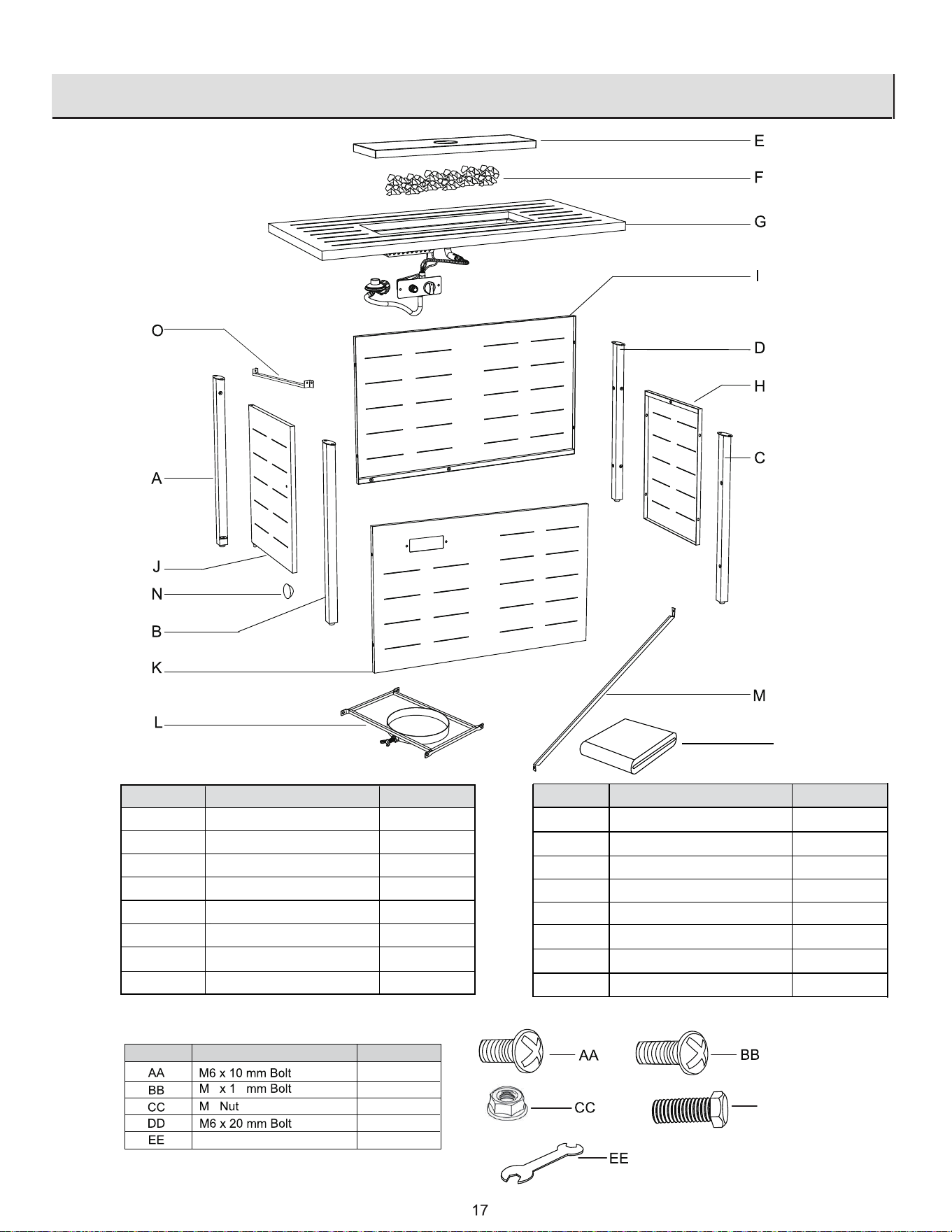
Service Parts
P
HARDWARE INCLUDED
Description Quantity
6 2
6
8
25
Wrench
DD
Part
Part
Quantity
A
1
B
1
C
Back Leg C
1
D
1
E
1
Description
Front Leg A
Front Leg B
Back Leg D
Metal Lid
Part
Quantity
I
1
J
1
K
1
L
1
Description
Door Panel
Side Panel with Window
Gas Tank Support
Connection Bar 1
F
1
Lava Rock
G
Table Top with Burner
1
M
Door Knob
1
N
1
Side Panel
H
Back Panel
1
1
Connection Bar 2
O
1
Protective Cover
P
2
1
1