
1
ACS
Series Intelligent Charger
Product Manual
We extend our sincerest appreciation for your purchase decision. For the best possible
functioning of this machine, it is essential to carefully study and keep this manual safe for
consultation whenever needed before commencing usage. (Version No. 1.0.5)

2
Contents
Chapter I. Warning Message ............................................................................................... 2
Chapter II. Overview ........................................................................................................... 1
1. Features ........................................................................................................................ 2
2. Key Features of the Charger ...................................................................................... 2
3. Normal Operating Conditions .................................................................................... 2
Chapter III. Key Technical Data ......................................................................................... 4
Chapter IV. Protective Features .......................................................................................... 5
Chapter V Dimensions of Brush Board and Brush Block ................................................. 6
Chapter VI Operating Instructions ................................................................................... 11
1. Overall Appearance of the Machine ........................................................................ 11
2. Diagrams of Telescopic and Floating Mechanisms ................................................. 14
3. Overall Diagram ........................................................................................................ 15
4. Panel Diagram ........................................................................................................... 15
5. Instructions for Emergency Stop Button ................................................................. 16
6. Instructions for Warning Light ................................................................................ 16
7. Instructions for Main Interface ................................................................................ 17
8. Wired Charging Mode Setup ................................................................................... 20
Chapter VIII Advanced Parameters Setup Procedure .................................................... 22
Chapter IX Debugging and Commissioning ..................................................................... 24
Chapter X WIFI Debugging .............................................................................................. 25
Chapter XI Modbus-RTU Protocol (Refer to the Modbus-RTU Protocol for Modbus-
TCP Protocol Resource Addresses) ................................................................................... 28
Chapter I.
1
Chapter I. Warning Message
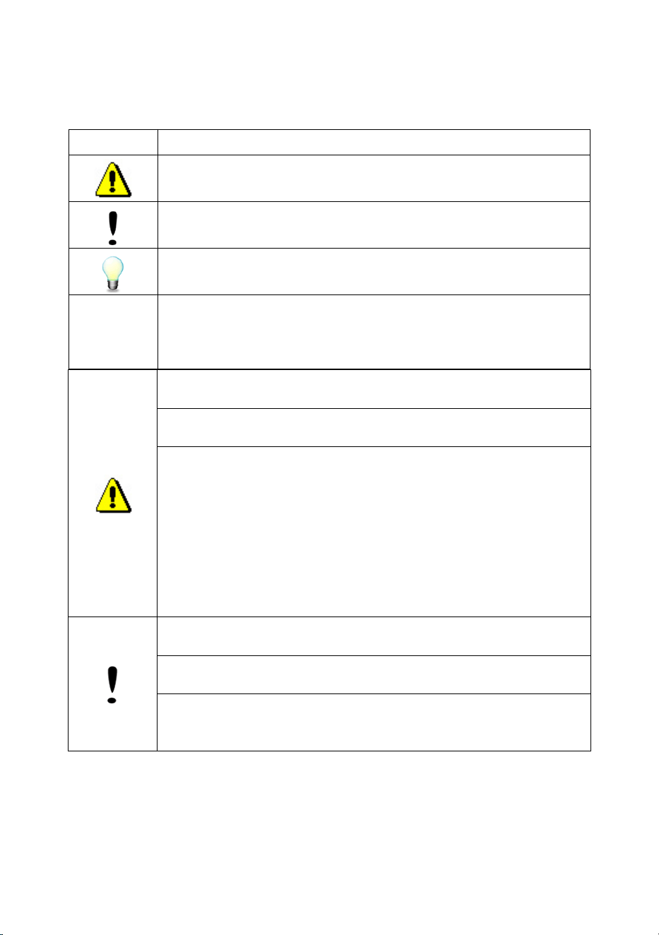
The following symbols are used to represent warnings and notes in this manual:
Symbols
Connotations
Danger: Risk of personal injury!
Caution: Risk of damage to charger or battery.
Note: Practical hints or useful information.
Prompt: Functional settings.
Only a duly certified professional electrical technician should install,
maintain, and repair this device!
The grounding of the charging station must be reliable and secure to
prevent anomalies from causing harm to individuals or property!
Since batteries may produce flammable and corrosive gases during the
charging process, it’s imperative to:
Stringently prohibit any open flames!
Avoid placing flammable or explosive materials around the charger
or battery!
Adequate ventilation is required in on the charging yard!
Do not disconnect the charging plug until the charger is switched
off. Otherwise, the resulting spark could ignite a fire or lead to an
explosion!
Under no circumstances should the charger be situated in an area prone
to water splashes, rainfall, or vapor exposure!
Mismatching the charged battery’s capacity and voltage with the
charger’s specifications may result in battery damage!
It is advisable to keep the charger as separate from the battery as
possible, or at a minimum, keep a distance of 1 meter or more to enhance
the charger’s durability!
We will not be liable for any outcomes due to non-compliance with operational
guidelines or unapproved technical alterations.
Should there be enhancements to the product’s performance, parameters, electrical
diagrams, or appearance that cannot be pre-announced, the actual product takes
precedence!
Chapter II. Overview

2
1. Features
The ACS series of intelligent chargers feature a modular design that integrates high-
frequency soft switch with DSP digitalization, offering high conversion efficiency and power
factor. The main circuit module, designed through parameter optimization, provides
continuously adjustable charging currents for a variety of AGV vehicles The ACS chargers
are designed with WIFI or infrared diffuse reflection and infrared direct transmission for smart
charging, resulting in a completely automated charging process. The chargers are equipped
with a variety of communication interfaces, allowing for data exchange with the majority of
lithium battery BMS and upper computers, etc.
The chargers feature a side-mounted automatic telescopic mechanism for quick and
convenient installation; it has a compact size and multiple redundant charging modules
connected in parallel for simple construction and safe and reliable operation.
Equipped with a 7/4.3-inch touchscreen, the charger allows for control of the charging
process, display of charging status, recording of charging data, and logging of fault
information. The charger also offers a professional configuration interface, enabling advanced
users to customize charging curves based on their specific needs.
2. Key Features of the Charger
1. The charger features an integrated design for charging station, complete with an
automatic telescopic mechanism for quick and convenient installation. (A separate version is
also available with split structure, where the ACS is not furnished with a telescopic mechanism)
2. Space is reserved for the installation of third-party equipment, providing the capability
for system integration.
3. The modular design allows for adaptability to a variety of AGV solution requirements.
4. The charger is designed with protective features against short circuit, overvoltage,
overcurrent, and overtemperature.
5. Both automatic and manual charging is available (reversing the connections is strictly
prohibited during forced charging).
6. The charger has various communication interfaces, including dry contact, CAN,
Ethernet, RS485, and WIFI (optional, to be configured to customer requirements).
7. The management background can perform real-time data queries on the charger
through various data interfaces such as CAN, RS485, and WIFI (optional, to be configured
based on specific customer requirements).
3. Normal Operating Conditions

3
(1) The height above sea level does not exceed 1000 m;
(2) The ambient medium temperature is within the range of -10°C to +45°C (inclusive);
(3) The relative humidity of the air should not exceed 95% (without condensation) when
the storage temperature is between -40°C and 75°C;
(4) The operating environment is free from conductive dust and explosive hazards;
(5) The operating environment is free from gases and vapors that may corrode metals or
insulation;
(6) Locations protected from rain and snow intrusion;
(7) Areas with a vertical surface tilt of no more than 5 degrees, and free from severe
vibration and shock.
4
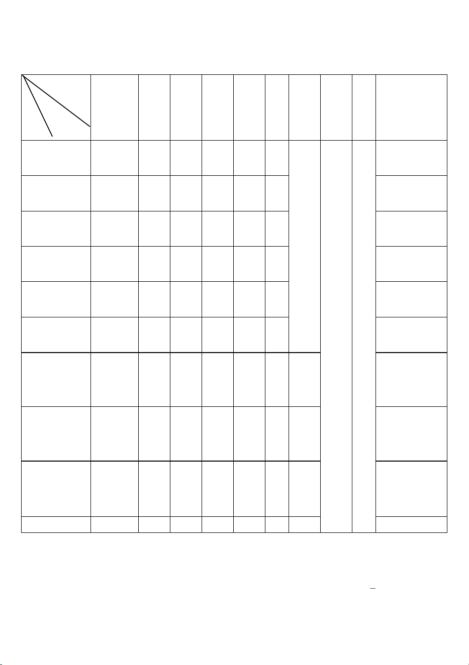
Chapter III. Key Technical Data
Items
Specifications
Parameters
Rated input
power supply
50 Hz
Rated
Input
power
kVA
Maximu
m input
Current
A
Rated
output
current
A
Output
voltage
range
V
Net
weig
ht of
main
devi
ce
kg
Net
weight
of side
charging
mechani
sm
kg
Means
of
commun
ication
Prot
ectio
n
Clas
s
Overall dimensions
ACS-E29.2V/100A
Single-phase
220
3.2
14.7
100
24-32
56
/
(Other
means
of
commun
ication
are
optional
)
IP20
710×400×1263
ACS-E58.4V/100A
Single-phase
220
6.5
29.5
100
48-60
60
710×400×1263
ACS-D58.4V/100A
Three-phase
380
6.3
9.5
100
48-100
60
710×400×1263
ACS-D58.4V/200A
Three-phase
380
13.4
20.4
200
20-120
94
772×500×1262
iACS-E58.4V/50A
Single-phase
220
3.2
14.7
50
48-68
72
710×400×1263
iACS-D100V/200A
Three-phase
380
21.5
32.7
200
20-120
130
772×500×1432
sACS-E29.2V/200A
Single-phase
220
6.5
29.5
200
24-32
63
41
710×400×1263/
(Dimensions of side
charging mechanism:
703×370×514)
sACS-E58.4V/50A
Single-phase
220
3.2
14.7
50
48-68
72
28
710×400×1263/
(Dimensions of side
charging mechanism:
390×595×343)
sACS-D29.2V/200A
Three-phase
380
6.5
9.9
200
24-32
67
55
710×400×1263
(Dimensions of side
charging mechanism:
768.5×500×850)
Note: The calculation method for custom specification parameters is as follows:
Input Power S (KVA) = Current * Voltage / Module Coefficient (depending on the
configured power module);
Input Current (A) = S / Power Supply Input Voltage (Single-phase);
Input Current (A) = S / (Power Supply Input Voltage (Three-phase)*
√
3).

5
Chapter IV. Protective Features
Items
Yes/no
Contents
Remarks
Input
undervoltage
Option
±15% of the rated input voltage
Protection: The fault
indicator light goes ON
when the device stops
working
Resumption: Operation
resumed after input voltage
returns to normal
Input
overvoltage
Output
overvoltage
Yes
Maximum charging voltage +2V
Protection: The fault
indicator light goes ON
when the device stops
working
Output
overcurrent
Yes
120% of rated current
(As above)
Reverse polarity
protection
Yes
When the charger is initiated for charging, if the
output polarity is detected to be reversed, the
charger will not start
Check the cause of the
protection activation
Short circuit
protection
Option
When the charger is initiated for charging, if an
output short circuit is detected, the charger will not
start
(As above)
Overtemperature
protection
Yes
If the temperature of the plug (brush) head is
greater than 90°C, an alarm will be triggered; the
alarm will be restored after the temperature drops
by 5°C.
When the temperature is
higher than 90℃, an alarm
will be triggered and the
machine will stop working.
The machine will resume
working after the
temperature drops by 5℃.
Ground
protection
Yes
/
The housing is fitted with
yellow-green lines for
ground protection
6
Chapter V Dimensions of Brush Board and Brush Block
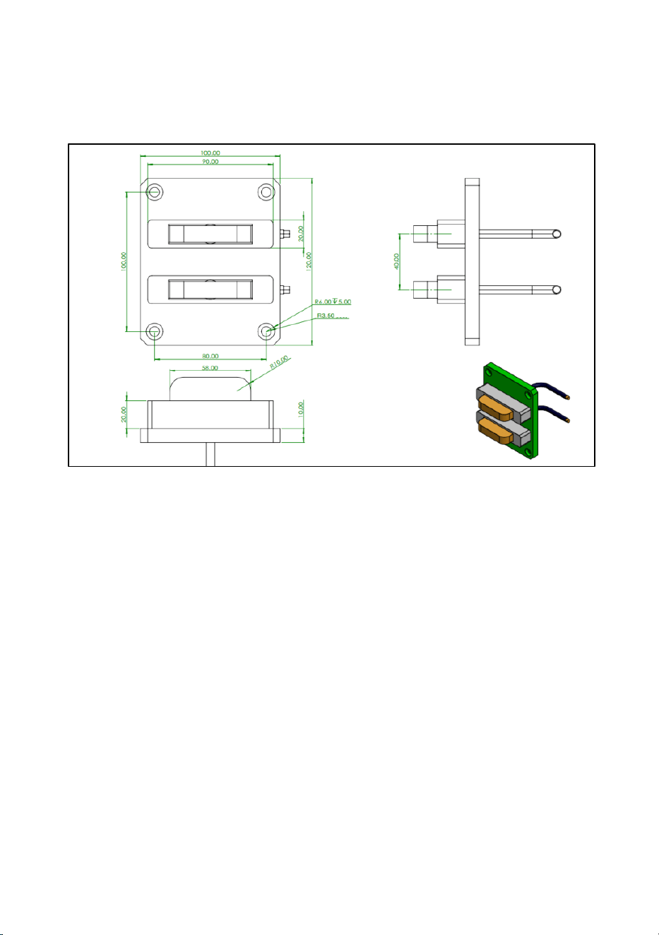
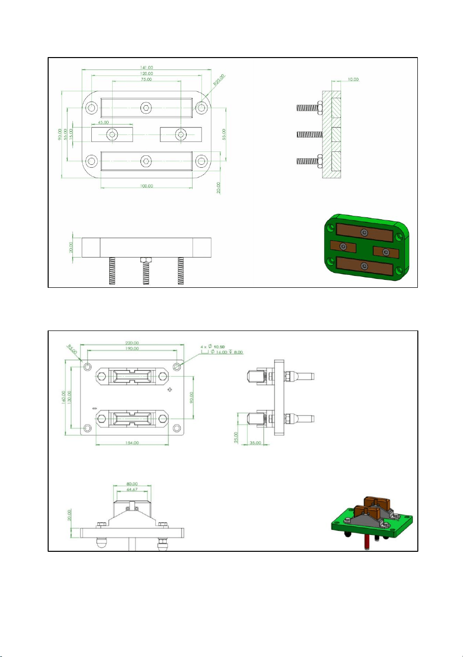
1. Dimensions of 100A Brush Block and Brush Board
100A
brush
block
100A brush board
Penetration
7
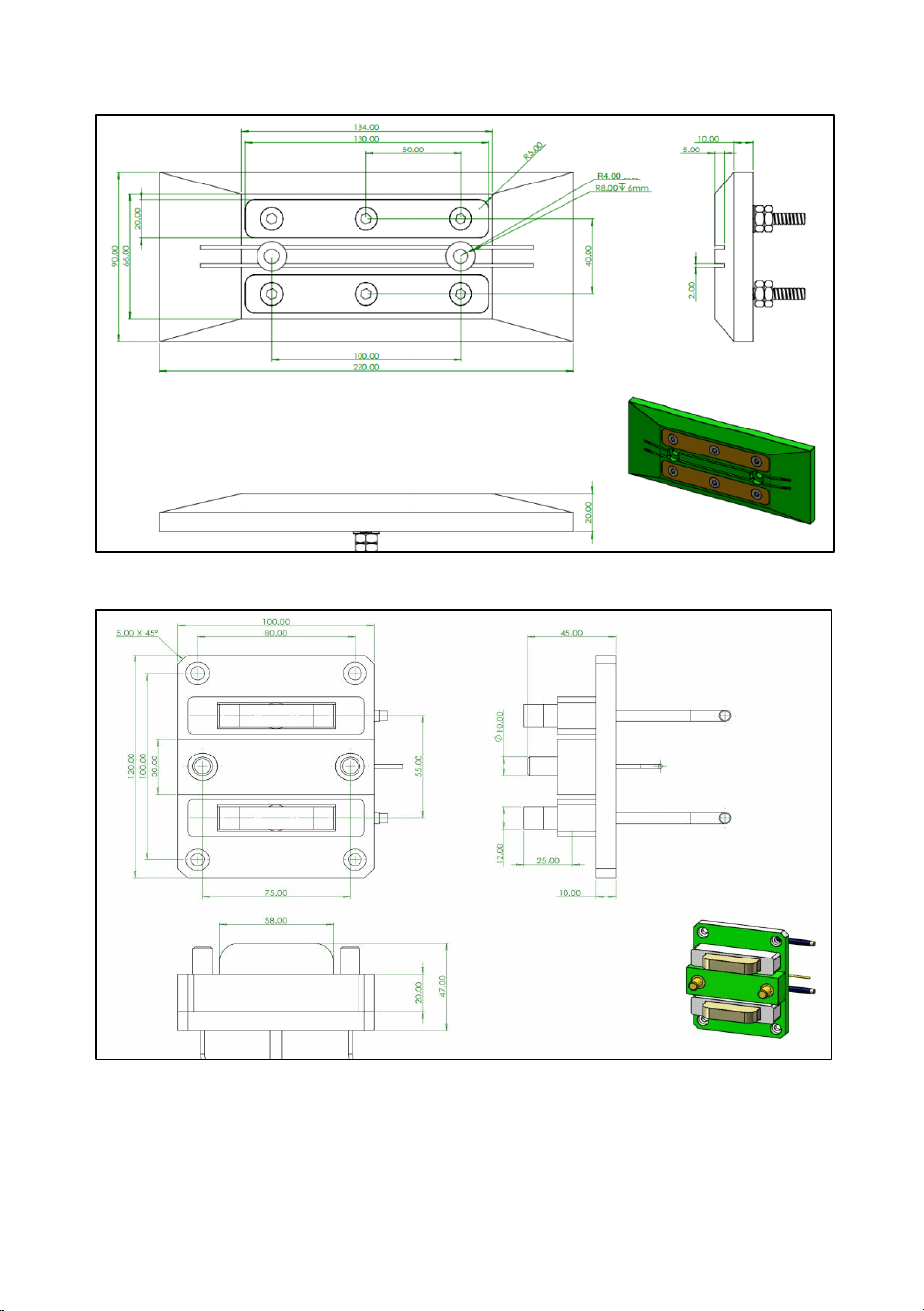
100A brush block, 4-pole contact
100A brush board, 4-pole contact
Penetration
8
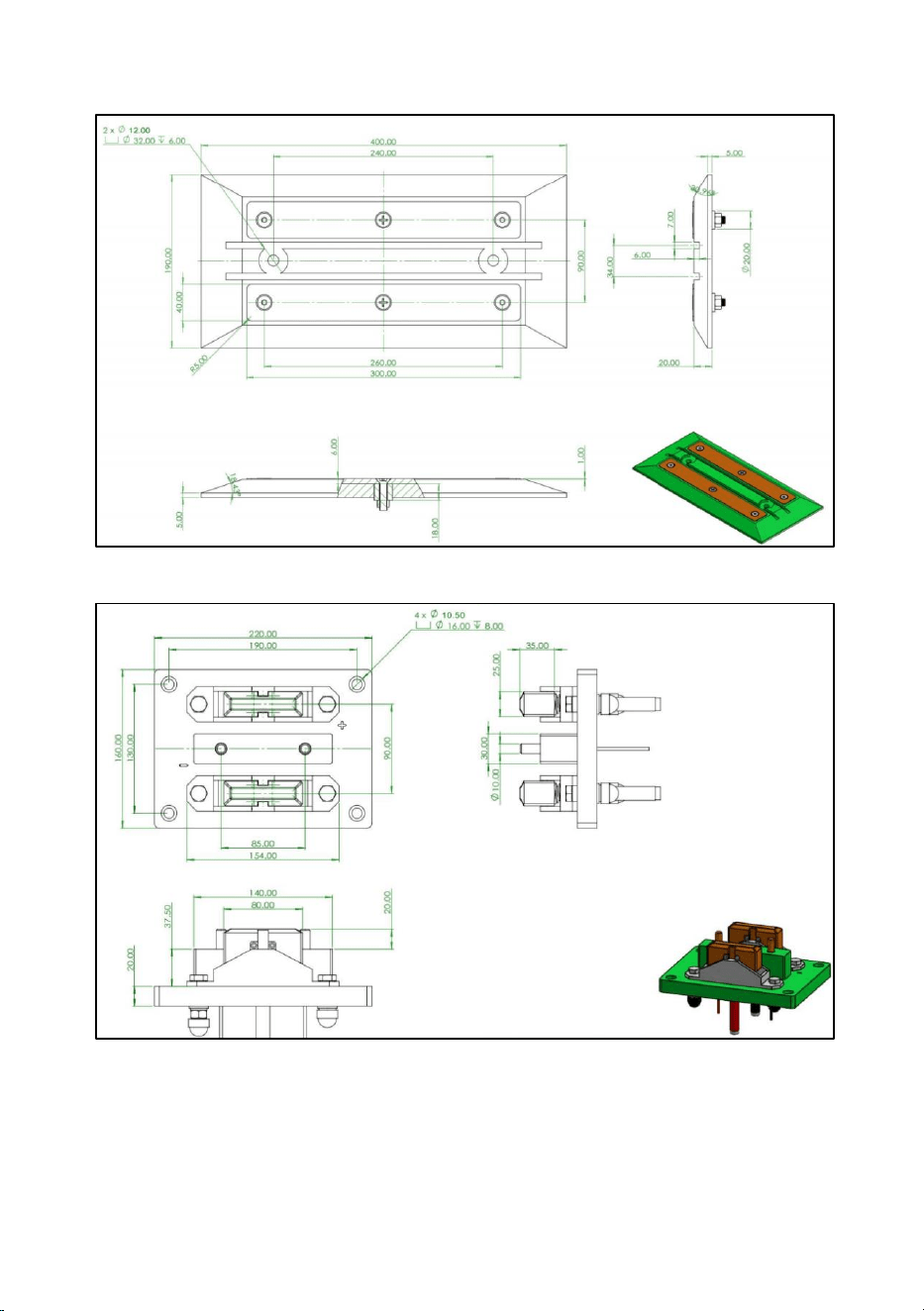
2. Dimensions of 200A Brush Block and Brush Board
200A brush block
200A brush board
Complete penetration
9
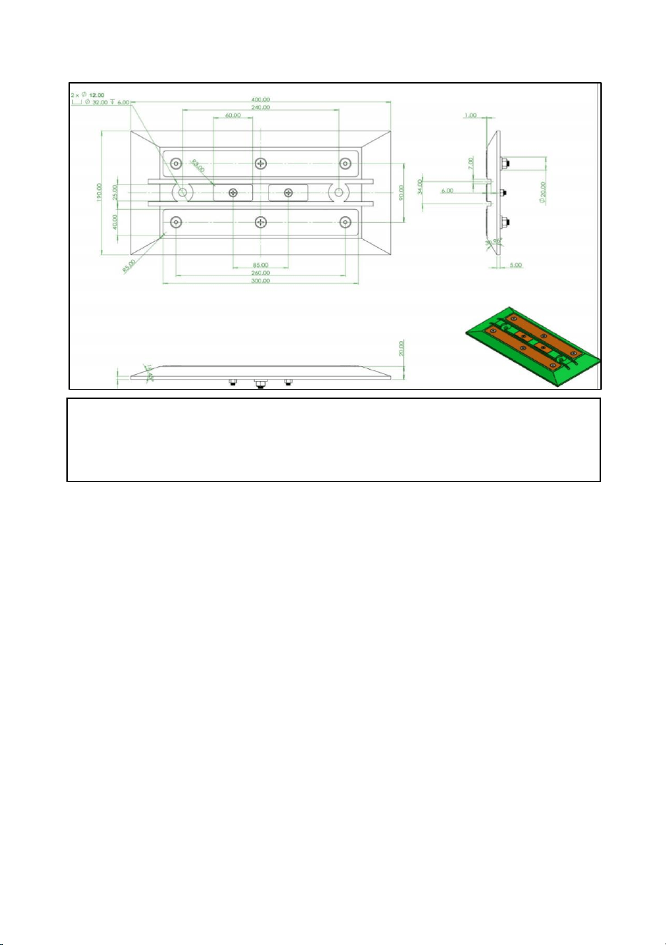
200A brush block, 4-pole contact
200A brush board, 4-pole contact
Complete penetration
Complete penetration
10
Precautions
The brush board and brush block must be used in pairs; do not use brush
boards and brush blocks that are not matched in size!
Complete penetration
11
Chapter 6 Operating Instructions
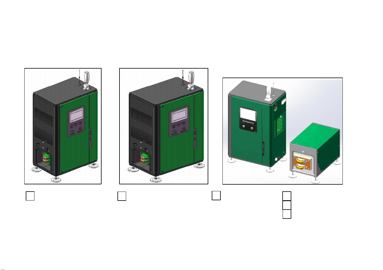
1. Overall Appearance of the Machine (Reference dimensions for standard edition are attached in mm; please refer
to the actual product)
710*400*1263 772*500*1262 710*400*1263 703*370*514
390*595*343
768.5*500*850
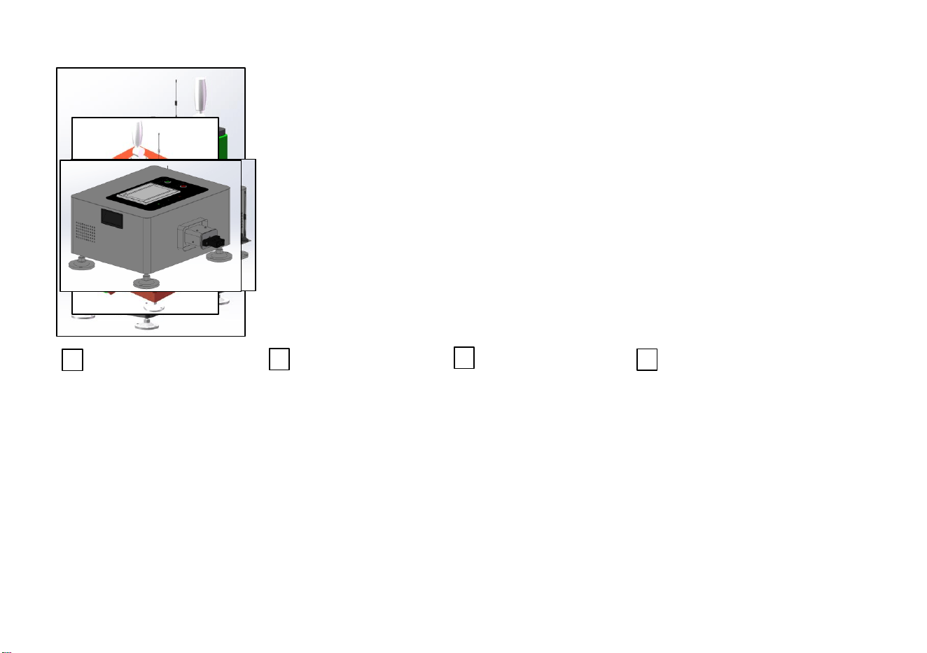
12
730*422*1000 530*615*796 545*570*276 545*570*276 (floating)
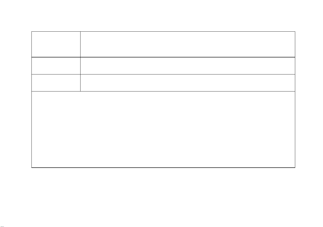
13
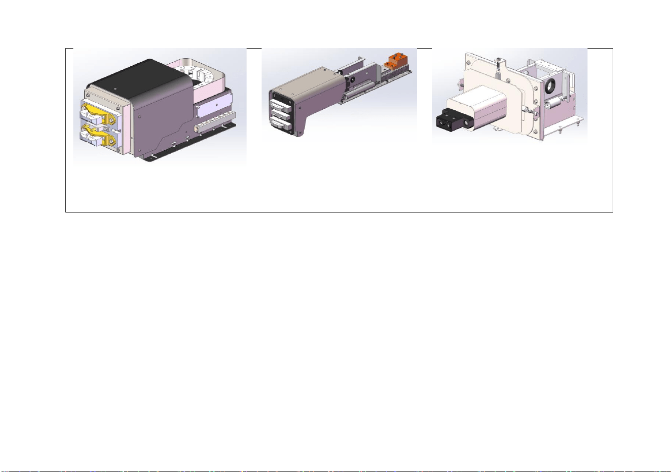
2. Schematic Diagram of Telescopic and Floating Mechanisms
Telescopic
Mechanism-1
Brush block: 50~200A available
Telescopic travel: Available in 200 mm and 300 mm
Telescopic speed: Available in 24 mm/s and 48 mm/s
Telescopic
Mechanism-2
Brush block: 30~50A available
Telescopic range: Customizable within the specified range
Floating mechanism
Plug: 30~50A available
Floating range: ±10 mm vertical; ±10 mm horizontal
14
Telescopic Mechanism-1
Telescopic Mechanism-2 Floating Mechanism
13
15
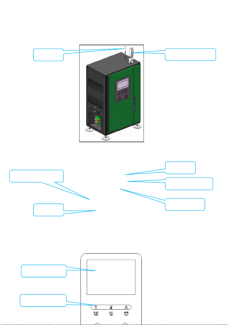
3. Overall Diagram
4. Panel Diagram
Antenna
Optical communication
Brush block
Tri-color indicator light
Touchscreen
Indicator light panel
Start/stop button
1. LCD touchscreen
2. Indicator light
16
1). LCD touchscreen - The human-machine interface of the charger, displaying the parameters
and status of the charging process, and offering the operation to set up the charger’s
parameters.
2). Charging status indicator light -
⚫ Power: The light is on when the indicator light’s power supply is functioning properly.
⚫ Run: The light is on when the charger is in the working state.
⚫ Fault: The light is on when the charger malfunctions; check the screen for the displayed fault.
3). Stop - This button is used to stop the charging station from charging.
4). Start - Where the charging station has the manual startup confirmation enabled, you need
to press this button once before the charging will initiate.
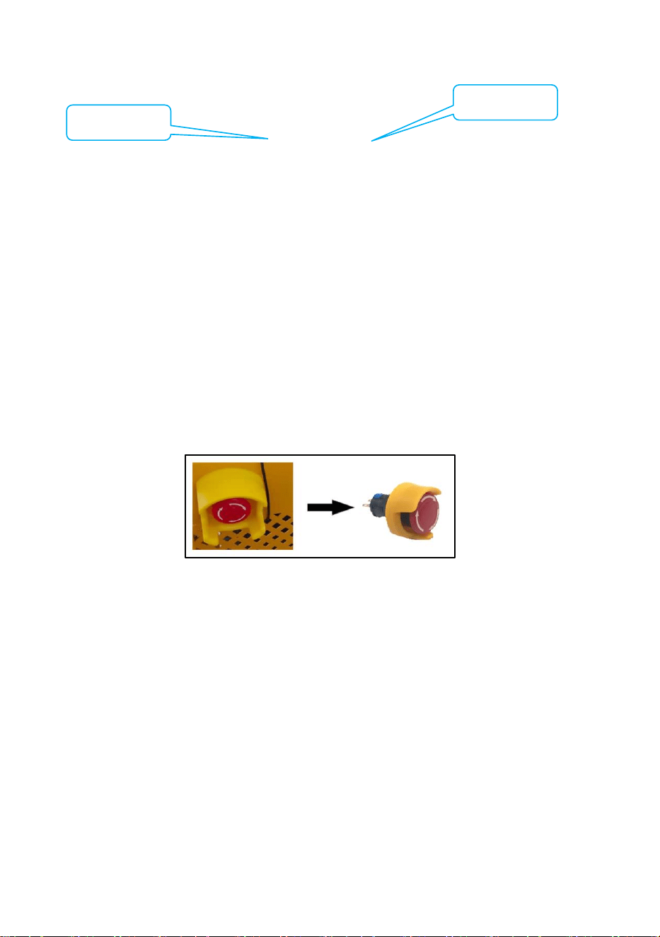
5. Instructions for Emergency Stop Button
⚫ Emergency stop button operation: In case of an emergency that requires immediate
cessation of charging, the operator is allowed to press the emergency stop button.
⚫ Emergency stop button reset: The depressed stop button does not automatically reset.
The operator must rotate the red button until it pops out, allowing the charger to be
powered on properly.
Precautions: The emergency stop switch is intended for emergency shutdown to prevent
exceptional electrical shocks or fires. Do not press this button during normal operation, since
this may lead to unnecessary repeated actions that may affect proper functioning.
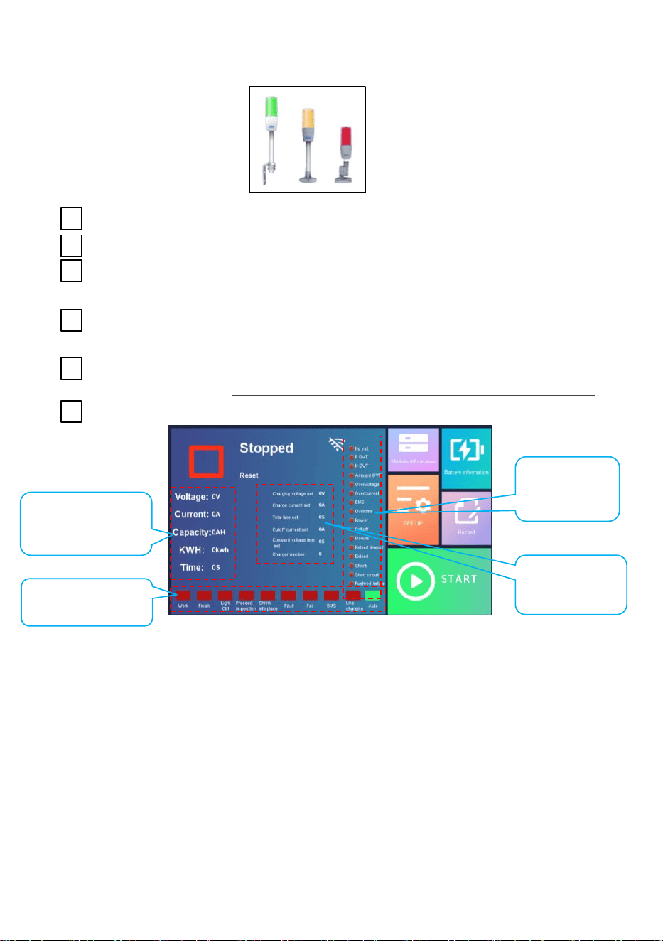
6. Instructions for Warning Light
3. Stop button
4. Start button
17
Definition 1: Red: Running Green: Full Yellow: Standby
Definition 2: Red: Fault Green: Running Yellow: Standby
Definition 3: Red: Fault, with buzzer activated Green: Flashing indicates “running”;
steady light indicates “full” Yellow: Standby
Definition 4: Red: Standby Green: Running Yellow: Flashing indicates fault, with
buzzer activated
Definition 5: Red: Running Green: Full & standby Yellow: Extending or retracting
Definition 6: (Optional)
7. Instructions for Main Interface
a. Current operating
state
b. Display
common settings
d. Fault
indicator light
c. State indicator light

18
Content
Supplementary description
a
Display
Voltage/Current/Capacity/Power
Consumption/Charging Time
b
Voltage Setting/Current
Setting/Charging Time Setting/Cut-off
Current Setting/Constant Voltage
Time Setting/Display Charging
Station Number
c
Work Light
The charger is currently working
Completion Light
Charging is complete.
Infrared Light Control Light
The charger has received an infrared signal
Pressed in Place Indicator Light
The mechanical arm extends and the brush
block is pressed in place
Retracted in Place Indicator Light
The mechanical arm retracts and reaches the
fully retracted position
Fault Indicator Light
All existing faults are indicated
Fan Indicator Light
Indicates the internal fan of the charger is
operating
Communication Indicator Light
Indicates communication with the BMS
Manual Charging Indicator Light
Indicates manual charging
Auto Charging Indicator Light
Indicates the charger is in automatic
charging mode
d
No voltage
Battery voltage detection timeout
Positive overtemperature
Charging positive brush block overheating
Negative overtemperature
Charging negative brush block overheating
Cyclic overtemperature
Excessively high ambient temperature of
charger
Overvoltage
Output overvoltage
Overcurrent
Output overcurrent
BMS
BMS reporting failure
Timeout
Communication with BMS timed out
Power
Input power failure

19
Disconnect
The brush block gets detached from the
brush board during the charging
Module
No charging modules are available
Extension timeout
The mechanical arm extends for longer than
the set time without pressing against the
brush board
Extended
Mechanical arm failed to extend
Retracted
Mechanical arm failed to retract
Short circuit
Charger output is short-circuited
20
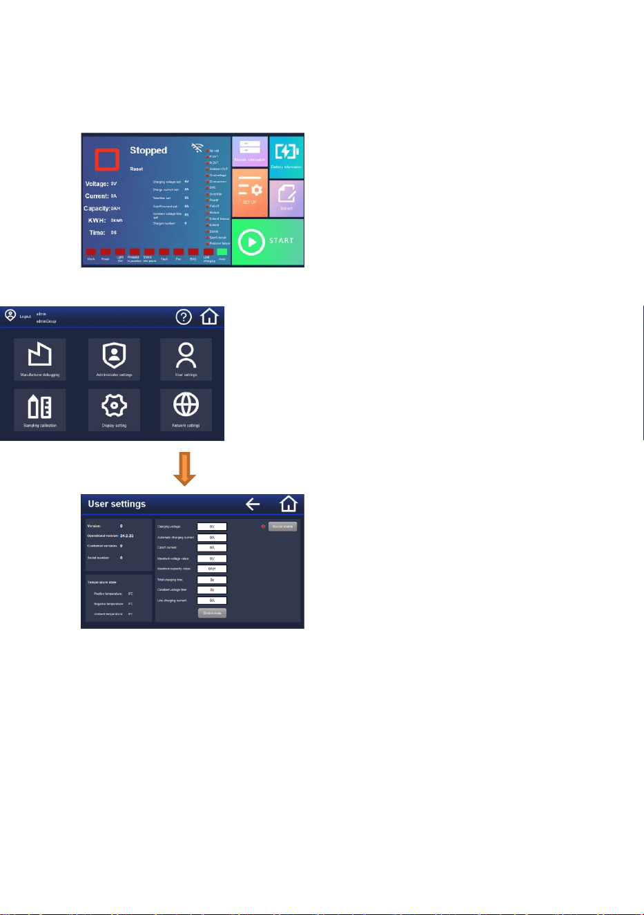
8. Wired Charging Mode Setup
[Click on Settings, and then click on Login in the top left corner – Select - User - Enter the
password 1234 – User Settings - Change to wired charging mode automatically]
21
Chapter VII Fault Description and Remedial Actions
Maintenance must be performed by professional electrical
technicians!
Fault
type
Fault
Code
Cause
Remedy
Charger
failure
E1
Battery voltage detection
timeout
Check whether the brush board is electrified or if there
is any poor contact
E2
Charging positive
overtemperature
Check for poor contact or whether the temperature
sensor is damaged
E3
Charging negative
overtemperature
Check for poor contact or whether the temperature
sensor is damaged
E4
Excessively high ambient
temperature
Check if the ambient temperature is too high or if the
temperature sensor is damaged
E5
Output overvoltage
Check if the battery malfunctions or if there is a sudden
drop in load
E6
Output overcurrent
Charging module malfunctions or gets damaged
E9
Input power failure
Check whether the power grid incoming line and the
corresponding wiring are correct.
E10
Battery disconnected
Check if the battery suddenly disconnects during
charging operation
E11
No charging modules are
available
Module damage or poor module communication
contact
E12
mechanical arm extension
timeout
Check if the telescopic mechanism’s wiring is in good
condition and if the auxiliary power supply is
functioning properly
E13
Mechanical arm failed to
extend
Check if the telescopic mechanism’s wiring is in good
condition and if the auxiliary power supply is
functioning properly
E14
Mechanical arm failed to retract
Check if the telescopic mechanism’s wiring is in good
condition and if the auxiliary power supply is
functioning properly
E15
Output short circuit
There is output short-circuit during charging operation
BMS
Fault
E7
BMS failure
Contact the manufacturer of battery
E8
BMS communication timed out
22
Chapter VIII Advanced Parameters Setup Procedure
Regular users do not need to set anything up here.
This setting interface is provided solely for users with special requirements; use the
following setup features with caution.
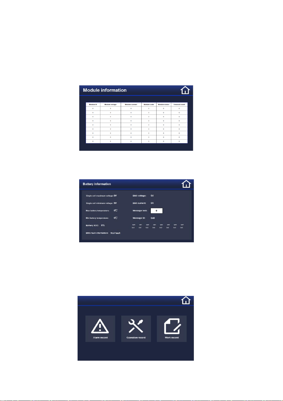
8.1.1 Module Information Interface
Click on “Module Information,” and the interface will display the module information
This interface shows the operating status of the charging module, including voltage, current, module operation
code, module state, module timeout counter, and other information.
8.1.2 Battery Information Interface
Click on “Battery Information,” and the interface will display the battery information
Indicates various types of information sent by the battery BMS, principally including:
Cell voltage information (maximum cell voltage, minimum cell voltage), battery temperature, SOC status, and
the voltage and current settings sent by the BMS.
The system features message capture and display. By entering the corresponding number for the locked message
ID, you can view the various data contained in the messages sent by the BMS.
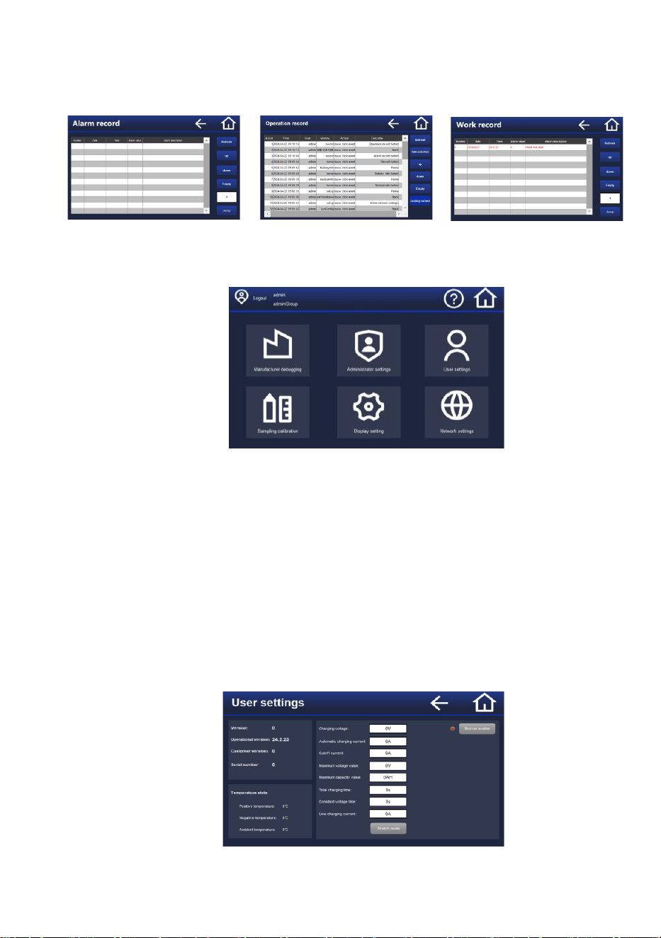
8.1.3 Record Interface
Click on “Record,” and you will enter the interfaces for “Alarm Record,” “Operation Record,” and “Work Record”
This interface provides a detailed record of various events and their occurrence times during the charging
23
operation, making it convenient for users to learn about the various operations performed by the charger and its
output status throughout the charging process.
Alarm Record Operation Record Work Record
8.1.4 Settings
Click “Settings” to get into the “Settings” interface
Click the login button in the top left corner, select the corresponding account in the pop-up information box, and
enter the password to complete the user login.
Regular user password (1234): You can only access the User Settings interface.
The Time Settings interface does not require login permissions.
The Sampling Calibration and Network Settings interfaces also require permissions above that of an
administrator.
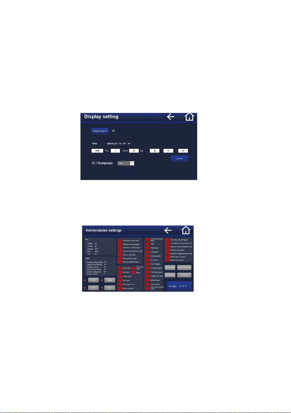
a) User Settings Interface
The User Settings interface allows you to view version information, temperature information, charging voltage,
24
self-charging current, cut-off current, maximum voltage value, maximum capacity value, total charging time,
constant voltage time, and wired charging current, etc.
You can switch between telescopic mode and wired charging mode (also known as manual blind charging). In
the wired charging mode, it is important to confirm the charging voltage value and the wired charging current
value. The charging voltage must not exceed the highest allowable charging voltage for the battery, and it should
be set with reference to the highest allowable charging voltage for the battery.
b) The Time Settings Interface and the Chinese-English Switching Interface
This interface is used to set the system time and to switch between Chinese and English.
Chapter IX Debugging and Commissioning
1. Operating Procedure for Manual Telescopic Mechanical Structure
1) Enter the administrator settings interface and enable manual extension & retraction
2) Click the manual extension button, and the mechanical telescopic mechanism will extend
3) Click the manual retraction button, and the mechanical telescopic mechanism will retract
2. Instructions for Setup of the Forced Start Mode
This mode is typically used when the battery protection board is locked due to
overdischarge protection, preventing the charging station from detecting the battery voltage.
Before using forced charging, it is necessary to confirm the charging voltage setting value;
it should not exceed the highest allowable charging voltage for the battery, and it should be
25
set with reference to the highest allowable charging voltage for the battery.
Ensure that the battery is not reversed and that the telescopic mechanism has reliable
contact before clicking the forced start button. The charging station will then skip the voltage
detection and directly start the forced charging.
Chapter X WIFI Debugging
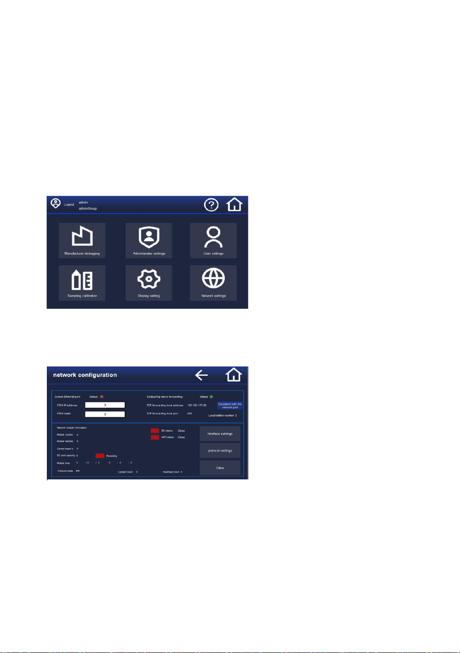
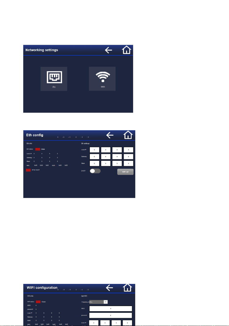
1. Go to the configuration page and click on Network Settings
2. The upper part is for network port configuration, which is part of the built-in
Modbus TCP port forwarding feature of the screen. The lower part is the
information page for the charger’s WiFi module
(1) Click on Interface Settings to enter the network port and WiFi connection settings
(2) In Protocol Settings, you can choose between MODBUS TCP protocol and the charger’s MODBUS TCP
port, with the charger acting as a slave
(3) Clicking on Other Settings allows you to enable WiFi module logging and SSH
(4) Connotations of the rectangular indicator lights: Red (off/not started/not connected); green
(on/started/connected)
the module time values should all maintain continuous growth
26
3. You can choose to connect via the network port or WiFi
4. In the network port settings, the left side displays the current network port information area,
and the right side is the area for setting and filling in the information
(1) If you want the charger to use the network port for connection, configure the IP, gateway, and subnet
mask of the network port, and then click Set. The Set button will turn blue and wait to turn gray before the setting
is successful. Check if the left side of the network port information area matches the current settings
(2) If DHCP is enabled, the local IP or gateway mask on the left may not match the settings area on the
right.
(3) Note the mask, gateway, or local IP settings; incorrect settings may lead to networking failure
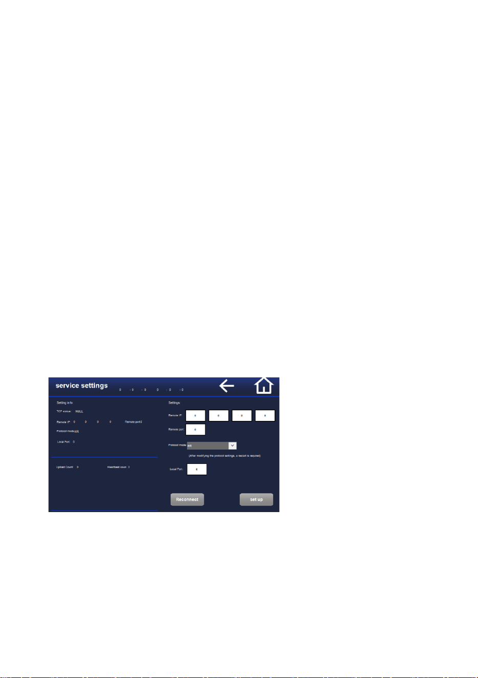
5. In the WiFi settings, the left side displays the current WiFi information area, and the right
side is the area for setting and filling in the information
27
(1) To enable the charger to connect using WiFi, configure the SSID, password, local IP, gateway, and
subnet mask, and then click Set. The Set button will turn blue and wait to turn gray before the setting is successful.
Check whether the left side of the WiFi information area matches the current settings
(2) If DHCP is enabled, the local IP or gateway mask on the left may not match the settings area on the
right.
(3) Note the mask, gateway, or local IP settings; incorrect settings may lead to networking failure
(4) The band can be set to ‘5G Only,’ ‘2.4G Only,’ or a specific band. If the band connected on the left side
of the information area is different from the one set, you can restart the charger to search for the specified WiFi
signal again. (If the current environment lacks a specified band, the charger may not connect to the band as set)
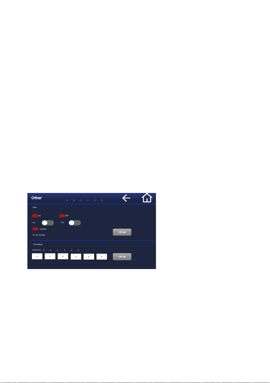
6. Protocol Settings (MODBUS TCP protocol to be chosen in normal
circumstances)
28
(1) The left side displays the current information area, and the right side is the area for setting and filling in the
information
(2) After setting the port, click the Set button. The button will turn blue and wait to turn gray before the setting
is successful, then check the left side for information
(3) The Disconnect and Reconnect button can break the current TCP connection, which is only used for
debugging purposes
(4) If the TCP status fails to connect for a long time, check whether there is an error in the WiFi settings
(5) After switching the protocol mode, click Set, and the charger needs to be restarted for the changes to take
effect
to connect to the charger’s IP and port number, and send modbustcp messages
MODBUSTCP message case:
00 01 00 00 00 06 01 05 00 03 ff 00 Start charging
00 02 00 00 00 06 01 05 00 07 ff 00 Reset
00 03 00 00 00 06 01 04 00 0d 00 01 Read the charging status, corresponding to resource list 3x14
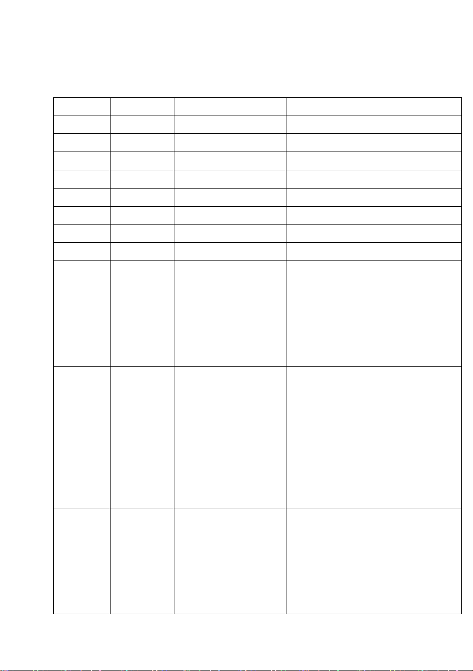
7. Other Settings
(1) The log switch can enable log recording, which requires inserting an SD card into the internal WiFi
module of the charger
(2) The SSH switch can enable SSH for the charger’s WiFi module, allowing for remote connection to the
WiFi module
(3) Upon completion of the setup, click the right side Set button, which will turn blue and wait for the button
to turn gray to indicate a successful setting
Chapter XI Modbus-RTU Protocol (Refer to the Modbus-RTU
23

29
Protocol for Modbus-TCP Protocol Resource Addresses)
1) Communication baud rate
a) 115200, 38400, 9600, and 4800 are optional
b) None Parity, data bit 8, stop bit 1
c) Parameter read interval ≥50 ms
2) Data format
Address code
Function code
Data Area
Error-Checking Code
8Bits
8Bits
N×8Bits
16Bits
3) CRC check
unsigned short CRC16puchMsg, usDataLen)
unsigned char"puchMsg ;/ Message to be CRC checked
unsigned short usDataLen ;/ Number of bytes in the message
{
unsigned char uchCRCHi = OxFF ;/ High CRC byte initialization
unsigned char uchCRCLo = OxFF ;// Low CRC byte initialization unsigned undex;/
Index in CRC loop
while (usDataLen--) / Transmission message buffer
{
ulndex = uchCRCHi^uchMsgg++ ;/ Computing CRC */
uchCR CHi = uchCRCLo ^ auchCRCHi[ulndex};
uchCRCLo = auchCRCLo[ulndex] ;
}
return (uchCRCHi << 8|uchCRCLo) ;
30
}
4) Resource list
3x01
u16
disp.vol
Voltage display with one decimal place, unit: V
3x02
u16
disp.cur
Current display with one decimal place, unit: A
3x03
u32
disp.cap
Capacity display with two decimal places, unit: AH
3x05
u32
disp.kwh
Quantity display with two decimal places, unit: kWh
3x07
u32
disp.ctimer1s
Charging time, unit: Second
3x09
s16
disp.temp1
Positive temperature, unit: °C
3x10
s16
disp.temp2
Negative temperature, unit: °C
3x11
s16
disp.temp3
Ambient temperature, unit: °C
3x12
u16
disp.version
Software version number
3x13
u16
disp.input_sigs
Input signal:
Bit0: Dry contact enabled
Bit1: Infrared reception
Bit2: Pressure block in place
Bit3: Retracted in place
Bit7: WiFi connection
3x14
u16
disp.output_sigs
Output signal quantity:
Bit0: Infrared transmission
Bit1: Wait for charging
Bit2: Fault
Bit3: Full
Bit4: Working
Bit5: Fan
Bit9: Output relay
3x18
u16
disp.event
Events:
21~24: Charging stage
41: Stop charging with total voltage
42: Stop charging with cut-off current
43: Stop charging with capacity
44: Stop charging with total time
26

31
45: Stop charging with stage time
46: Stop charging with bms
47: Manual suspension
3x20
u16
disp.errors
Fault:
bit0:E1 Battery voltage detection timeout
bit1:E2 Charging positive overtemperature
bit2:E3 Charging negative overtemperature
bit3:E4 Excessively high ambient temperature
bit4:E5 Output overvoltage
bit5:E6 Output overcurrent
bit6:E7 BMS fault
bit7:E8 BMS communication timed out
bit8:E9 Input power failure
bit9:E10 Reserved
bit10:E11 No charging modules are available
bit11:E12 Mechanical arm extension timeout (non-
manual control)
bit12:E13 Mechanical arm failed to extend
bit13:E14 Mechanical arm failed to retract:
4x24
u16
cmp.cv_specS
Charging voltage setting, with one decimal place, unit:
V
4x25
u16
cmp.cv_specS
Charging current setting, with one decimal place, unit:
A
4x27
u16
cmp.end_curS
Charging cut-off current setting, with one decimal place,
unit: A
4x32
u16
cmp.max_time1S
Charging time setting, unit: s
4) Principal Operation Example
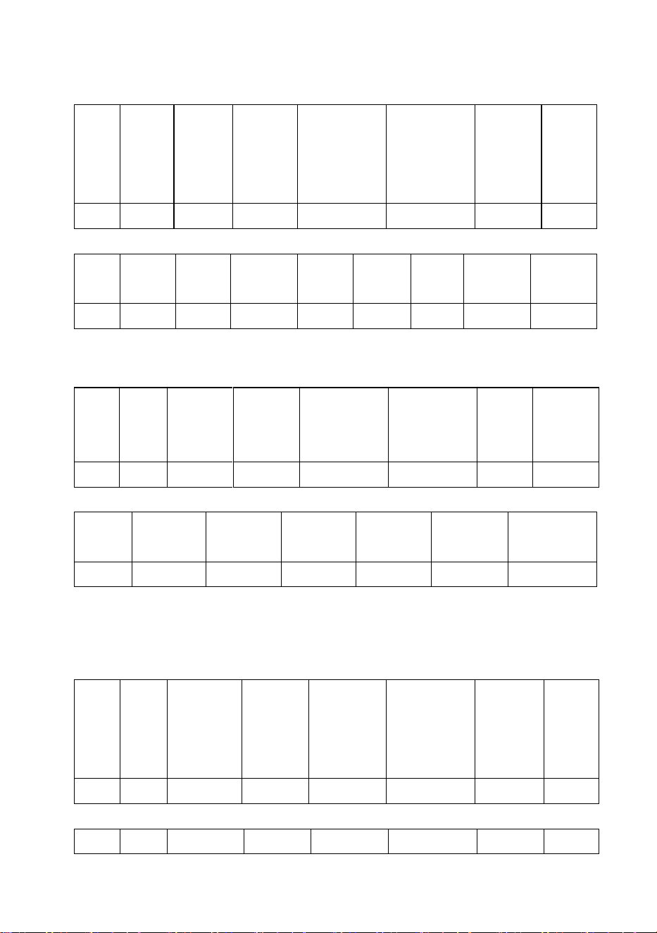
a) Read the current voltage and current: (Read 3x read-only resources, function code 04, the
address for sending the command = resource address - 1)

32
33
PLC sending:
Station
number
Function
code
Head
address
(High byte)
Head address
(Low byte)
Read WORD count
(High byte)
Read WORD count
(Low byte)
CRC check
(Low byte)
CRC
check
(High
byte)
0x01
0x04
0x00
0x00
0x00
0x02
0x71
0xCB
Charging station reply: For example, the current voltage is 58.4V, 200.0A
Station
number
Function
code
Byte count
Data I
High byte
Data I
Low byte
Data II
High byte
Data II
Low byte
CRC check
(Low byte)
CRC check
(High byte)
0x01
0x04
0x04
0x02
0x48
0x07
0xD0
0x79
0x86
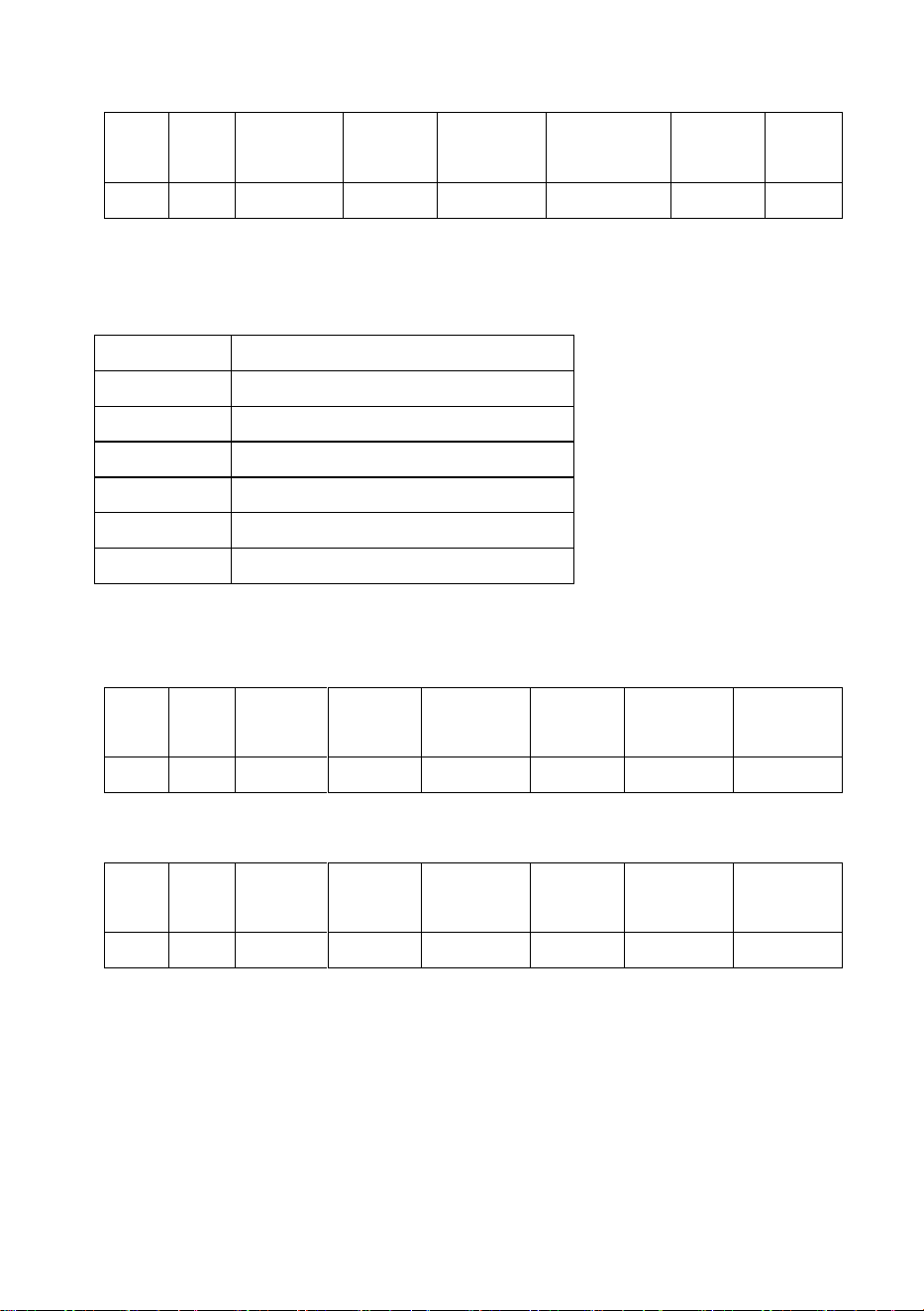
b) Read the charging voltage Settings: (Read 4x read-only resources, function code 03, the
address for sending the command = resource address - 1)
Station
number
Function
code
Head address
(High byte)
Head address
(Low byte)
Read WORD count
(High byte)
Read WORD count
(Low byte)
CRC
check
(Low byte)
CRC check
(High byte)
0x01
0x03
0x00
0x17
0x00
0x01
0x34
0x0e
Charging station reply: For example, the current voltage is set to 58.4V
Station
number
Function code
Byte count
Data I
High byte
Data I
Low byte
CRC check
(Low byte)
CRC check
(High byte)
0x01
0x03
0x02
0x02
0x48
0xb9
0x12
c) Set charging voltage: (Write 4x read-only resources, function code 06, the address for
sending the command = resource address - 1)
Assuming the written voltage to be 83.4V
Station
number
Function
code
Head address
(High byte)
Head address
(Low byte)
Write into
WORD
(High byte)
Write into WORD
(Low byte)
CRC check
(Low byte)
CRC
check
(High
byte)
0x01
0x06
0x00
0x17
0x03
0x42
0xb9
0x0f
Charging station reply
Station
Function
Head address
Head address
Write into
Write into WORD
CRC check
CRC check
34
number
code
(High byte)
(Low byte)
WORD
(High byte)
(Low byte)
(Low byte)
(High byte)
0x01
0x06
0x00
0x17
0x03
0x42
0xb9
0x0f
d) Operation button
0x address (address starting from bit1)
0x01
Manual extension button
0x02
Manual retraction button
0x03
Forced start button
0x04
Start button
0x05
Pause button
0x07
Stop button
0x08
Reset
Operate above-noted buttons:
Write: Stop the charging station Function code 0x05 The bit address also needs to be
reduced by 1
Station
number
Function
code
Head address
(High byte)
Head address
(Low byte)
High byte written
Low byte
written
CRC check
(Low byte)
CRC check
(High byte)
0x01
0x05
0x00
0x04
0xff
0x00
0xcd
0xfb
Reply
Station
number
Function
code
Head address
(High byte)
Head address
(Low byte)
High byte written
Low byte
written
CRC check
(Low byte)
CRC check
(High byte)
0x01
0x05
0x00
0x04
0xff
0x00
0xcd
0xfb
Note: 0xff00 is for requesting the coil ON, while 0x0000 is for requesting the coil OFF.
Suggestions for operation shutdown: 1. Stop charging by pressing the manual suspension
button; 2. Press the Reset button after detecting the retracted-in-place signal in the
disp.input_sigs address 3x13

35
Please take attention that changes or modification not expressly
approved by the party responsible for compliance could void the
user’s authority to operate the equipment.
This device complies with Part 15 of the FCC Rules. Operation is
subject to the following two conditions:
(1) This device may not cause harmful interference, and
(2) This device must accept any interference received, including
interference that may cause undesired operation.
This equipment complies with FCC radiation exposure limits set
forth for an uncontrolled environment. This equipment should be
installed and operated with minimum distance 20cm between the
radiator & your body.