1

2
Table of Contents
Preface ........................................................................................................................... 4
1.1 Copyright ................................................................................................... 4
1.1.1 Copyright 2025-2026 ......................................................................... 4
1.1.2 Trademarks ......................................................................................... 4
1.2 Safety Warnings ........................................................................................ 4
1.3 Introduction .............................................................................................. 5
1.4 Technical support ...................................................................................... 5
1.5 Disclaimer .................................................................................................. 5
1.6 Your comments .......................................................................................... 5
2 Product Overview ................................................................................................... 6
2.1 Introduction .............................................................................................. 6
2.2 Product package ........................................................................................ 6
3 Installation .............................................................................................................. 8
3.1 Overview ................................................................................................... 8
3.2 Steering system inspection ....................................................................... 8
3.3 Original steering wheel removal ............................................................... 8
3.4 Steering wheel installation ....................................................................... 9
3.5 Receiver installation ................................................................................ 11
3.6 Tablet installation .................................................................................... 12
3.7 Camera installation ................................................................................. 12
3.8 Wiring connection ................................................................................... 13
4 Main interface ....................................................................................................... 16
5 Quick guide ........................................................................................................... 19
5.1 Power On ................................................................................................. 19
5.2 Boot guide ............................................................................................... 19
5.3 Software registration .............................................................................. 19
5.4 GNSS settings .......................................................................................... 20
5.5 Vehicle settings ....................................................................................... 21
5.6 Calibration ............................................................................................... 24
5.6.1 Steering calibration .......................................................................... 24

3
5.6.2 Installation error calibration ............................................................ 25
5.7 Implement settings ................................................................................. 26
5.8 Basic guidelines ....................................................................................... 27
5.8.1 AB line .............................................................................................. 27
5.8.2 A+ line .............................................................................................. 28
5.8.3 Free curve ........................................................................................ 29
5.9 Engage and disengage automatic steering ............................................. 31
5.10 Power Off ................................................................................................ 31
6 Maintenance ......................................................................................................... 32

4
Preface
1.1 Copyright
1.1.1 Copyright 2025-2026
CHCNAV and CHC Navigation are trademarks of Shanghai Huace Navigation
Technology Ltd. All other trademarks are the property of their respective owners.
1.1.2 Trademarks
All product and brand names mentioned in this publication are trademarks of their
respective holders.
1.2 Safety Warnings
When using the CHCNAV NX600 Series GNSS Automatic Steering System, please
observe the following safety warnings:
Before using the system, carefully read and understand the operating instructions in
the user manual to ensure proper use of the system.
During system operation, strictly follow local traffic regulations and safety standards
to ensure safe operation in safe environments and conditions.
Regularly check the condition and performance of the system and equipment when
using the system to ensure normal operation and high-precision navigation
performance.
Maintain concentration and alertness during system operation, avoid fatigue and
distraction, and prevent accidents.
Avoid using the system in hazardous areas such as steep or cliff edges, water puddles,
or muddy ground to prevent personal injury or equipment damage.
Stop using the system immediately and contact the system manufacturer or supplier
for technical support and maintenance services when the system experiences
abnormality or failure.
Protect the equipment from physical damage or weather factors when operating the
system to ensure long-term stability and reliability.
Observe the relevant maintenance and upkeep requirements of the system and
equipment during operation to prolong the life of the equipment and ensure normal
operation.
Pay attention to the safety of the surrounding environment and other personnel
when using the system to avoid accidents and stop the machine promptly to handle
any abnormal situations.
The above is for reference only, and specific safety warning content may vary slightly

5
depending on the device model and local regulations and standards. When using the
CHCNAV NX600 Series GNSS Automatic Steering System, please carefully read and
observe the relevant safety warnings and usage instructions to ensure the safety and
normal operation of the system.
1.3 Introduction
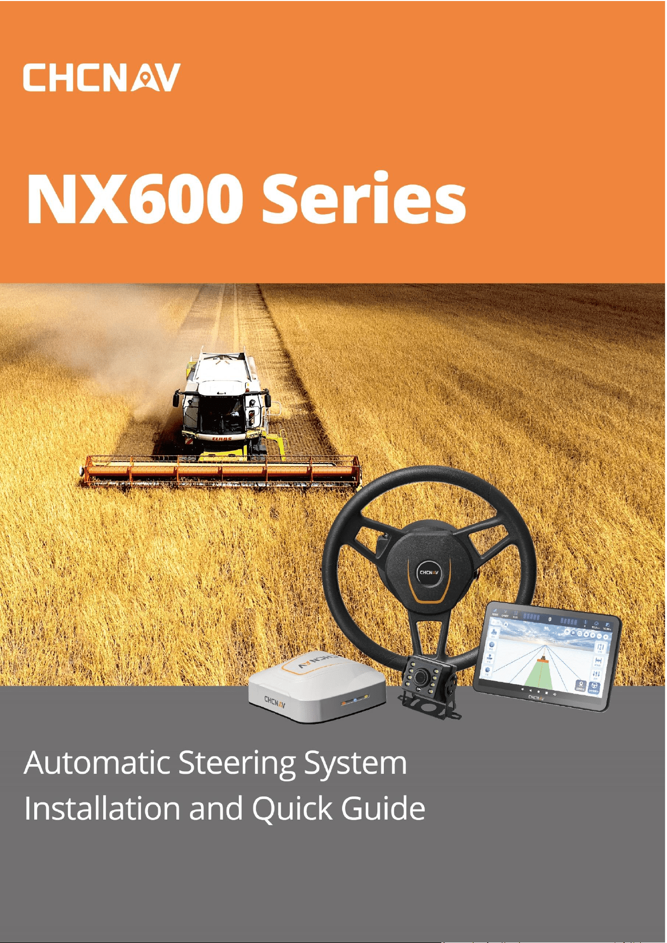
The CHCNAV NX600 Series user manual describes how to install and use the
CHCNAV® NX600 Series system. In this manual, “the system” refers to the NX600
Series agricultural system unless otherwise stated. Even if you have used other
agricultural products before, CHCNAV recommends that you spend some time
reading this manual to learn about the special features of this product.
1.4 Technical support
If you encounter a problem and cannot find the required information in this manual
or on the CHCNAV website (www.chcnav.com), please contact your local CHCNAV
dealer from whom you purchased the system.
If you need to contact CHCNAV technical support, please contact us by email
support_ag@chcnav.com
1.5 Disclaimer
Before using the system, please make sure that you have read and understood this
User Guide, as well as the safety information. CHCNAV holds no responsibility for the
wrong operation by users and for the losses incurred by the wrong understanding
about this User Guide. However, CHCNAV reserves the rights to update and optimize
the contents in this guide regularly. Please contact your local CHCNAV dealer for new
information.
1.6 Your comments
Your feedback about this user guide will help us to improve it in future revision.
Please email your comments to support_ag@chcnav.com.
6
2 Product Overview
2.1 Introduction
The NX600 Series is an automatic steering system that can be easily retrofitted to
many types of vehicles, providing a compact, modern, all-in-one solution at an
affordable price. It delivers significant productivity gains, operates in all visibility
conditions, and reduces operator fatigue.
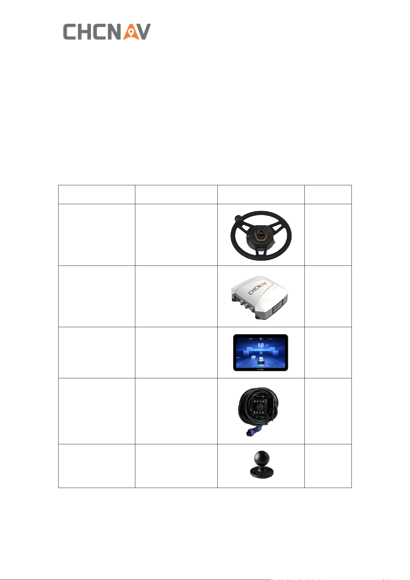
2.2 Product package
All components are in one box.
Device name Model Image Quantity
Electric steering
wheel
CES-T6
1
Receiver PA-5
1
Tablet
CB-H12(T)
CB-H10 Pro(T)
1
Camera X-MC011A
1
Ball holder
2
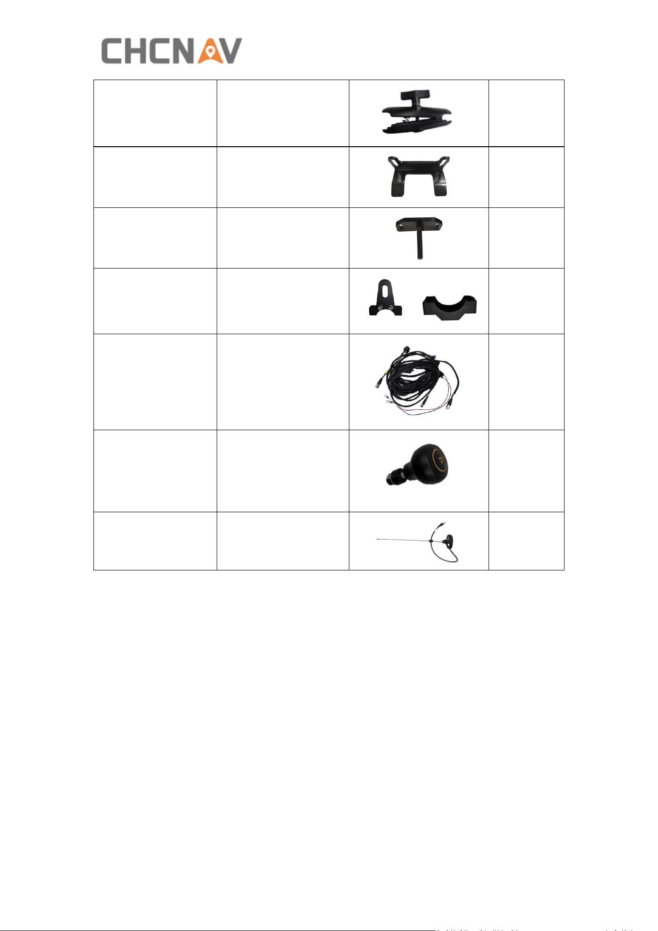
7
Double socket arm
1
Standard bracket
1
T-bracket
1
T mount kit (A&B)
B A
1
Integrated main
cable
1
Handle ball
1
Radio Antenna
1
8
3 Installation
3.1 Overview
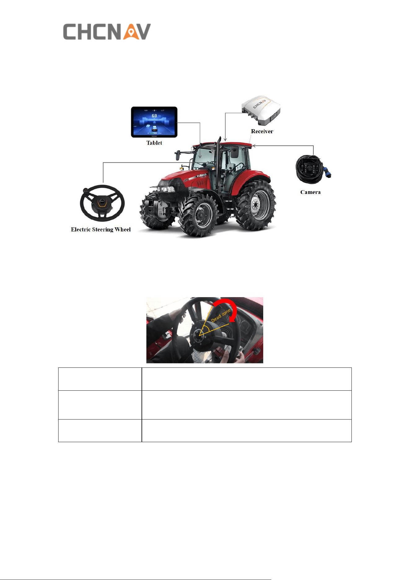
3.2 Steering system inspection
Before installation, please check whether the vehicle steering gear is normal,
whether the dead zone (steering clearance) is appropriate.
Dead zone<20°
Available range
20°<Dead zone<70°
Available to install NX600 Series but necessary to modify
the dead zone to 10~30 degrees.
Dead zone >70°
Repair the vehicle first.
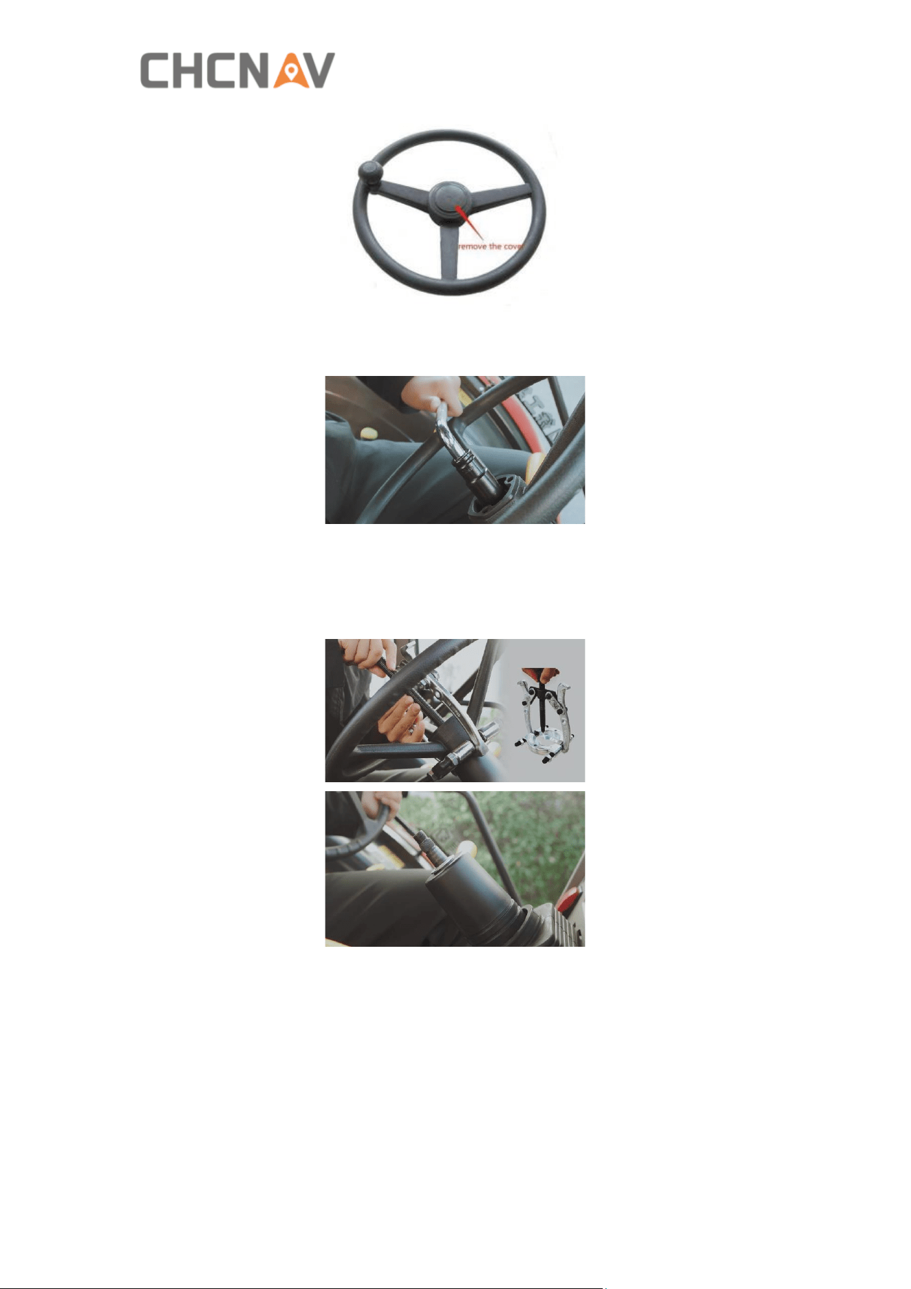
3.3 Original steering wheel removal
a) Remove the protective cover of the original steering wheel.
9
b) Stabilize the steering wheel, use the sleeve tool to loosen the original vehicle
spline screws, and remove the original vehicle spline screws.
c) Pull out the steering wheel forcefully. If it is difficult to remove, it is necessary to
strike the spline shaft to loosen it with a hammer and to be careful to avoid the
steering wheel damage, or use of high-quality puller tool to avoid damage on original
steering wheel and shaft.
3.4 Steering wheel installation
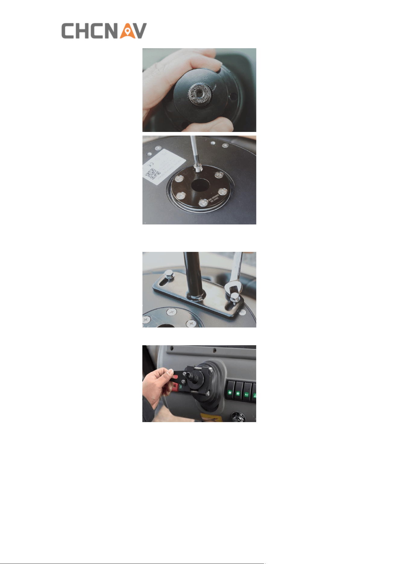
a) If the sleeve can fit the shaft, place the sleeve in electric steering wheel, and fix
the sleeve with M5*11 Phillips screws (6 pcs).
10
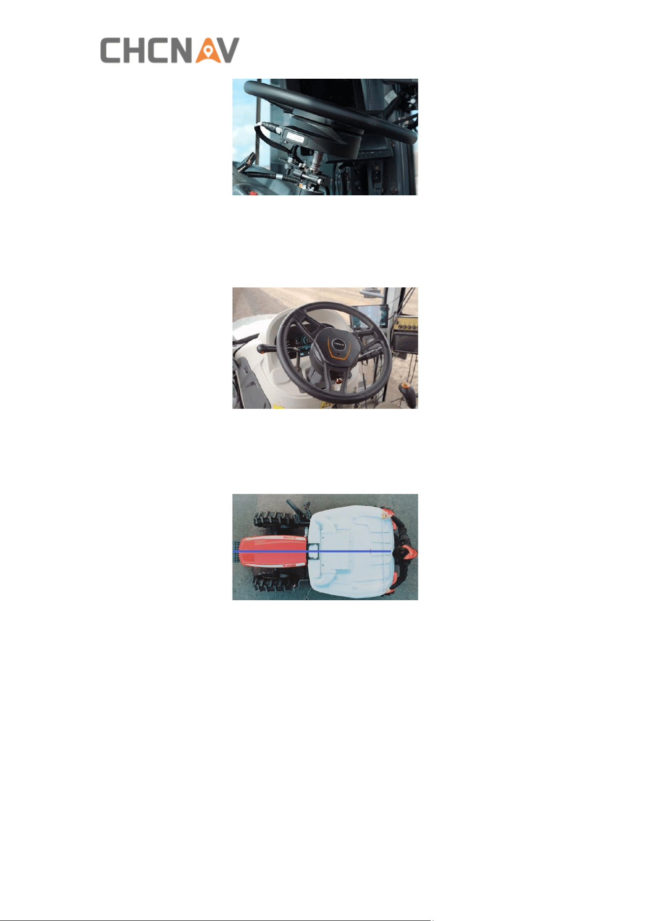
b) Install T bracket or standard bracket on the motor with M5*16 hexagon screws (2
pcs).
c) Fix the T mount kit to the shaft with M8*60 hexagon screws (2 pcs).
d) Insert T bracket through T mount kits.
11
e) Hold the steering wheel and tighten the spline screws with tools.
f) Screw the T bracket to the T mount kit tightly with M10 nuts (2 pcs).
g) Finally shake the steering wheel, check whether it’s tight, and check again whether
the steering clearance is too large.
3.5 Receiver installation
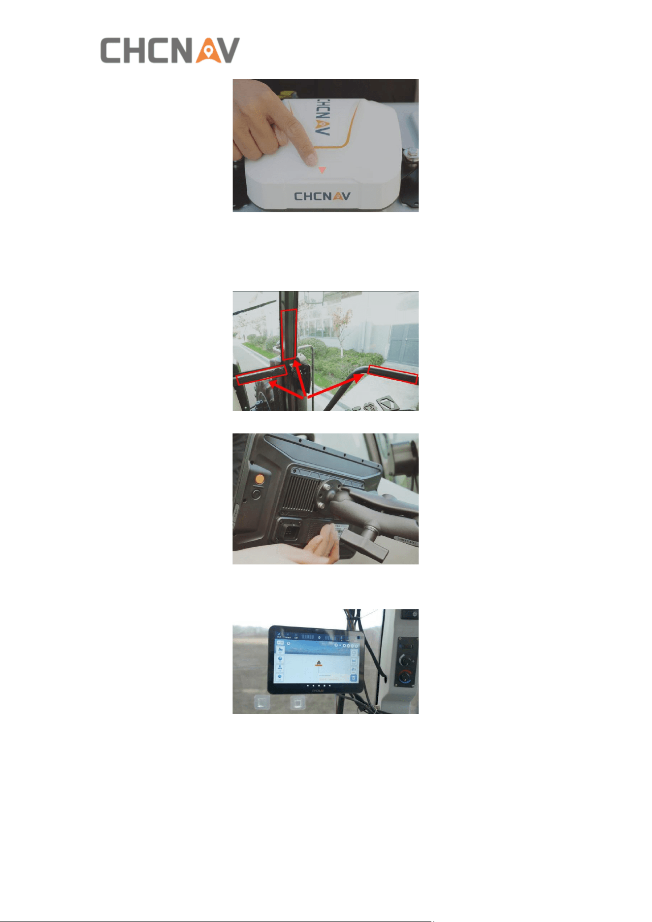
a) The receiver needs to be installed on the central axis of the vehicle roof, and the
installation direction should be parallel to the vehicle heading.
b) After confirming the installation position, wipe the roof clean and make sure the
bracket installation is spotless.
c) Fix the receiver using 3M adhesive or self-tapping screws.
d) Adjust the receiver bracket to make sure the receiver is placed horizontally (the tilt
angle must be less than 5°) and the receiver arrow must face forward.
12
3.6 Tablet installation
a) The tablet should be installed in a location convenient for user operation. It is
recommended to mount the ball base on the handrail using the U-shaped brackets.
b) Secure the tablet using a rotating mount.
c) After completing the installation, it is available to adjust the tablet to a suitable
position.
3.7 Camera installation
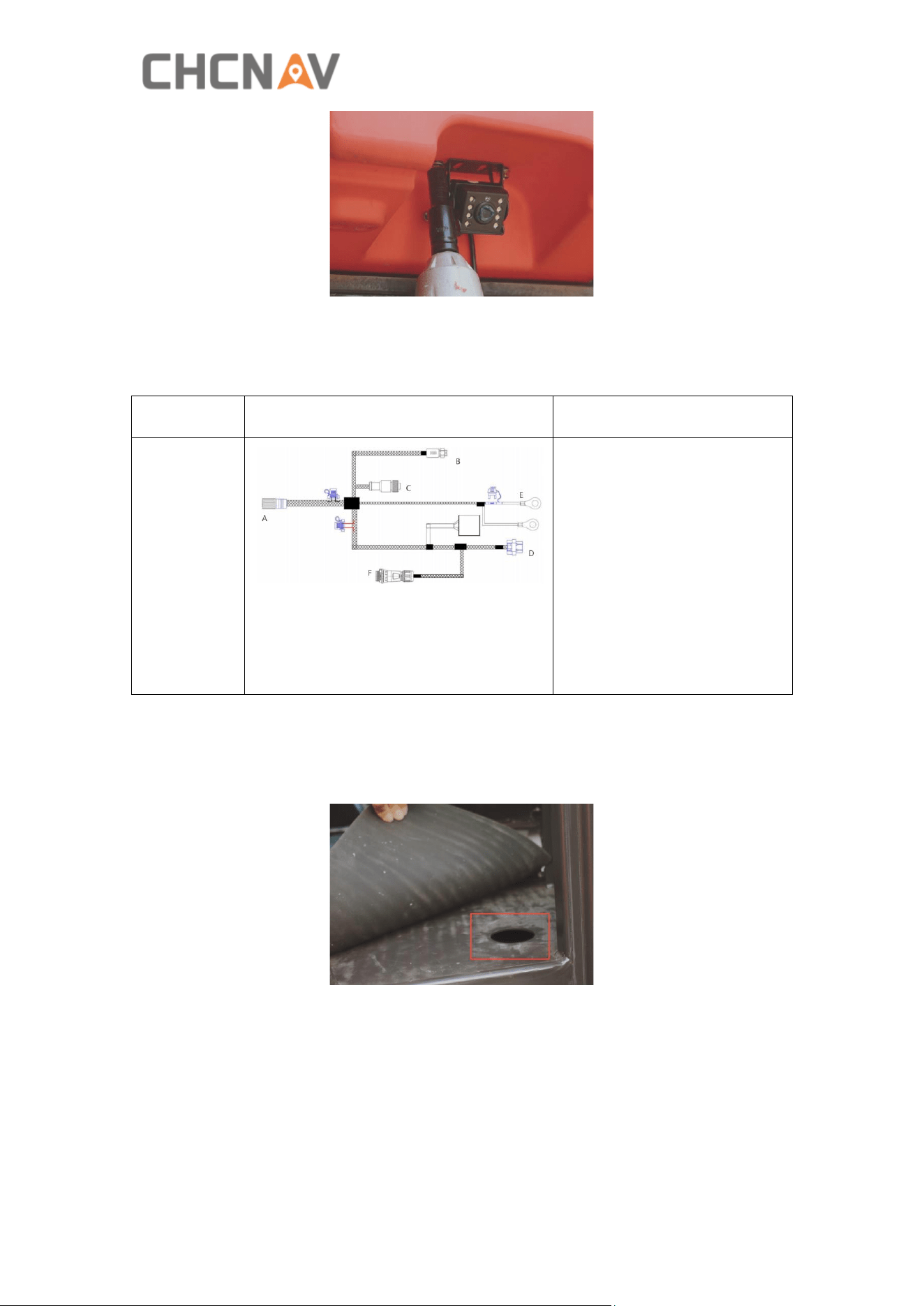
a) The camera can be mounted anywhere at the rear of the vehicle to monitor
real-time working conditions.
b) Fix the camera with 3M adhesive or self-tapping screws.
13
3.8 Wiring connection
Name
Cable diagram
Connection
Integrated
main cable
A → Receiver
B → Electric steering wheel
C → Wheel angle sensor
cable (Optional)
D → Tablet Port
E → Battery
F → Camera
G: Rocker switch
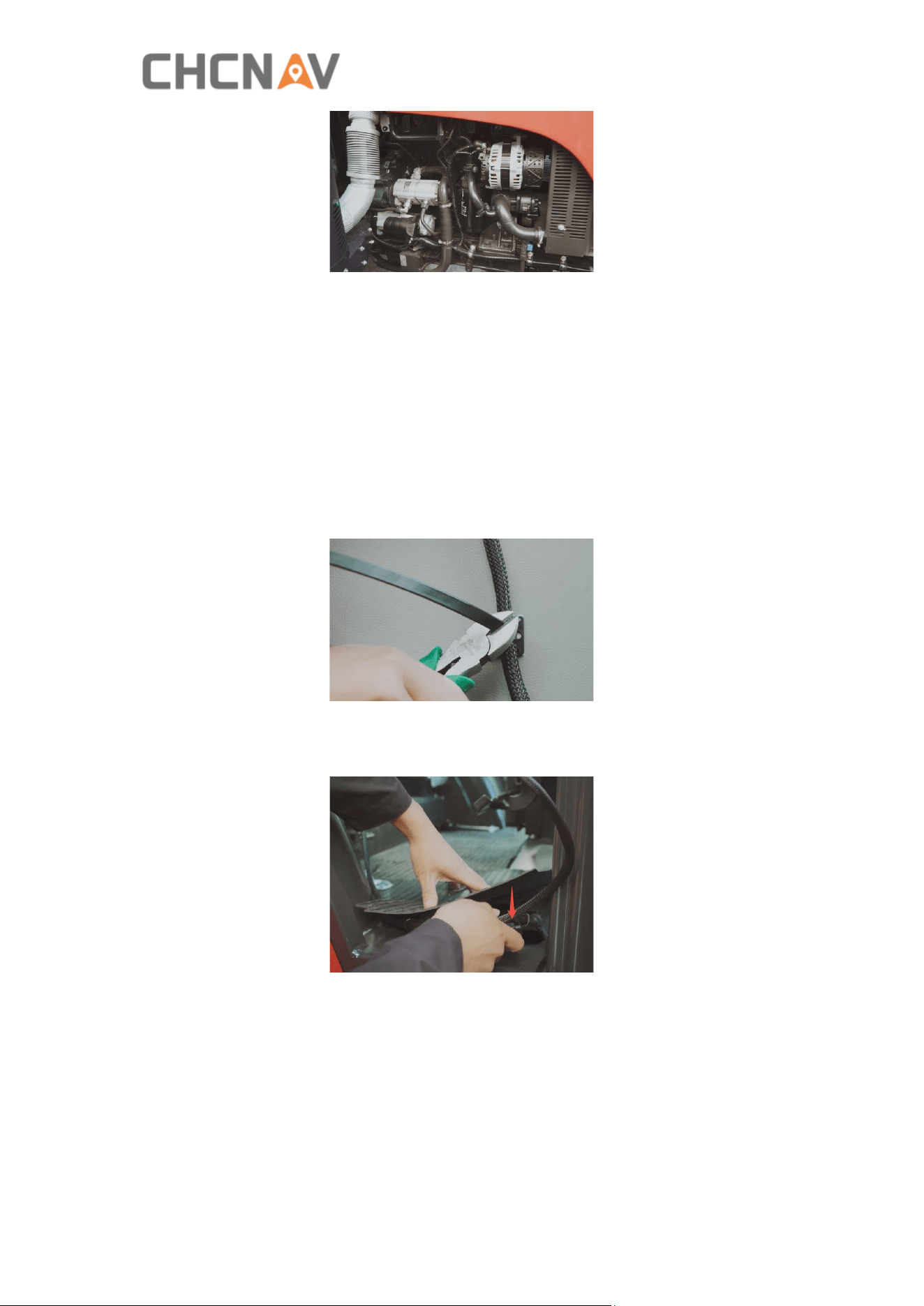
a) Wiring precautions
· When wiring, first confirm the location of the threading holes, and thread the
wiring harnesses outside through the threading holes in sequence.
· When wiring, pay attention to avoid high temperature, oily, sharp and abrasive
areas, fans, exhaust pipes and other nearby areas.
14
· When wiring, keep a certain length to avoid over-tightening and loosening; the
wiring harnesses layout should be smooth and cannot be twisted.
· When wiring, leave enough length in case of wheel turning to right/left all the way
because the wheel angle sensor will rotate together with steer wheel.
· When wiring, first arrange the outer wiring harnesses, then arrange the wiring
harnesses in the cab.
· After wiring, cut off the extra length of cable ties.
· After completing the installation, please store the original vehicle accessories
properly and clean up the garbage.
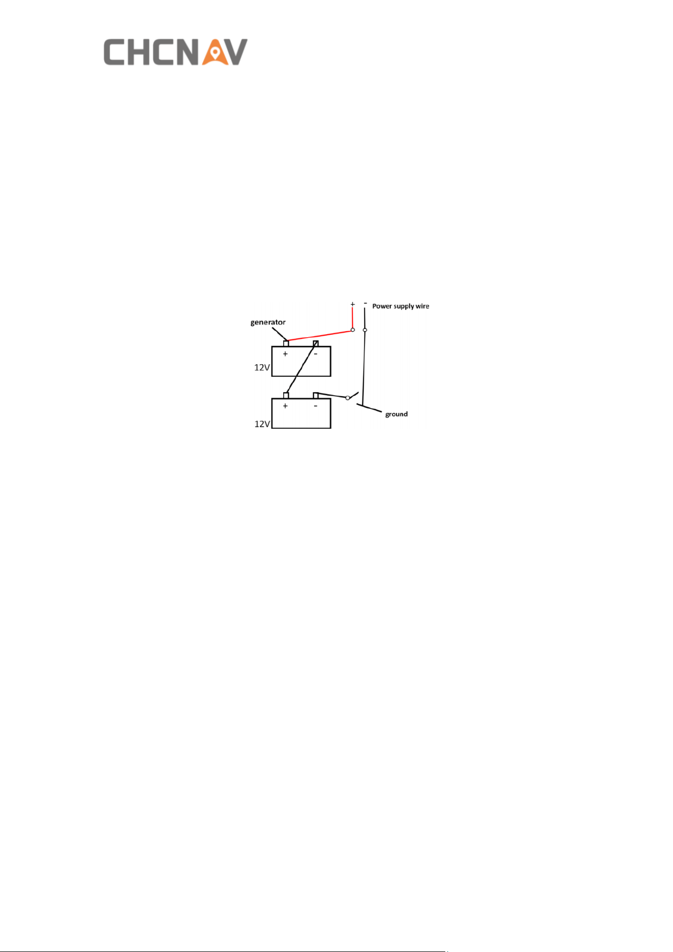
b) Electrical connection method and precautions
· Before connecting to receiver, display, and steering wheel connectors, please
connect to battery first to avoid damage caused by direct power-on or multiple
power-offs.
· In the process of connecting the power cord to the battery, first connect to the
positive electrode then to the negative electrode.
15
· Pay attention to the use of the wrench when connecting the positive electrode, and
it is strictly forbidden to bond (when the wrench contacts the positive electrode of
the battery, the other end of the wrench is strictly prohibited from touching any
conductive items, especially the metal parts of the original vehicle).
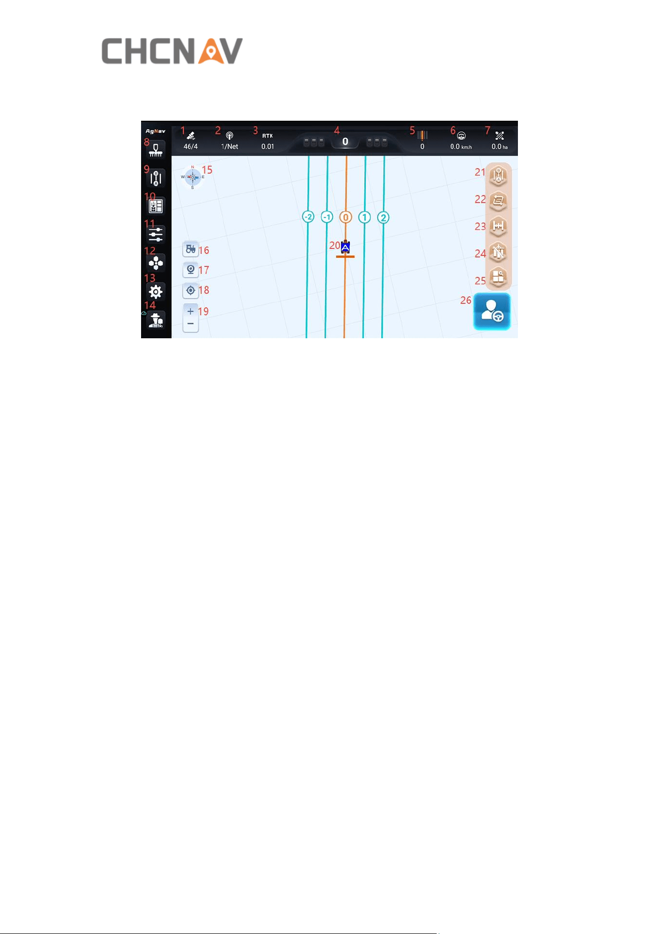
· 12V / 24V battery, when using the original battery power supply, please connect
the positive wire to the positive electrode and the negative wire to the negative
electrode.
· 12V / 24V battery, when additional battery is connected in series, connect the
positive wire to the positive electrode and the negative wire to the negative
electrode of the other battery, as shown in the diagram below.
16
4 Main interface
1. Satellite status
There are two numbers displayed in the form of X / Y.
X represents the number of tracked satellites.
Y represents the RTK status:
1: Single/Autonomous 2: DGPS/SBAS 4: Fix 5: Float
2. Base station status
There are two numbers displayed in the form of X / Y.
X represents the signal latency. The smaller the X, the more stable the signal is,
usually the recommended value is less than 10 in automatic steering mode for better
performance.
Y is the current radio channel number if it’s radio mode; Y will change to NET if it’s
network mode.
3. GNSS mode and position accuracy
4. Lateral deviation
The real-time deviation between the current vehicle location and the marked
guideline.
5. Guideline number
The current guideline number where the vehicle is located (The original number is 0).
6. Vehicle speed
Real-time vehicle speed.
7. Worked area
Display real-time work area, ha is the default unit.
8. Implement
It consists of Implement parameter, Implement menu, Center offset and ISOBUS

17
switch.
9. Guideline
Click this button, then select the type of guideline to create.
10. Field managers
It is accessible to manage boundaries, guidelines, tasks, and landmarks quickly.
11. Parameter adjustment
P Gain: Motor Adjustment speed ratio. The smaller the value, the slower the
adjustment.
D Gain: The higher the frequency, the more obvious the vibration of the motor
movement; the smaller the frequency, the more stable the motor movement.
12. UI style
Includes Day/Night and 2D/3D mode switch.
13. Settings center
Includes three modules: Agriculture management, System settings and Data transfer.
14. About
Includes Help, Me and Equipment modules.
Help interface: Includes Remote assistant, One click log upload, Parameters and
Reverse heading features.
Me interface: Cloud service login interface.
Equipment interface: It is possible to view the device's basic information and version
information.
15. Compass
Click it once to check the basic information. Click it seven times continuously to show
the debugging information.
16. Vehicle speed
Vehicle speed in demonstration mode. You can adjust the vehicle speed and direction
in the demonstration mode.
17. Camera switch
Turn the camera on or off.
18. View switch
Switch between map orientation or vehicle orientation.
19. Zoom in/out
Click to zoom in/out on the screen.
20. Vehicle and guideline
Display vehicle and guideline positions.
21. Quick creation
Quickly create AB line, Free curve or Boundary.
22. Guideline switching button
Click the button to quickly switch guidelines when the field has multiple guidelines.
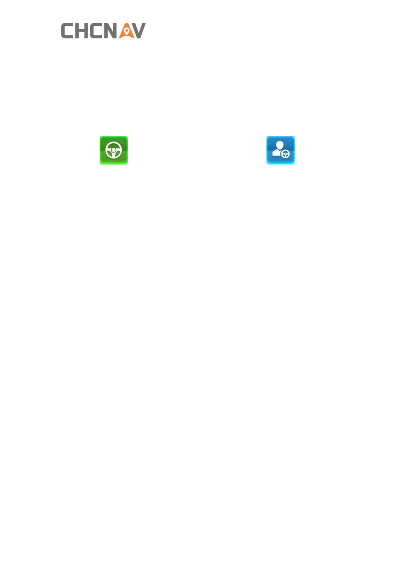
18
23. Line offset
Shift guidelines as needed.
24. Work coverage track
Turn on track recording.
25. All shortcuts
View all shortcuts or configure shortcuts.
26. Engage or Disengage
Automatic: Manual:
19
5 Quick guide
5.1 Power On
Press and hold the orange button for 3 seconds to power on the system.
Note: Please do not turn the steering wheel manually when turning on the system
because the motor will initialize internally.
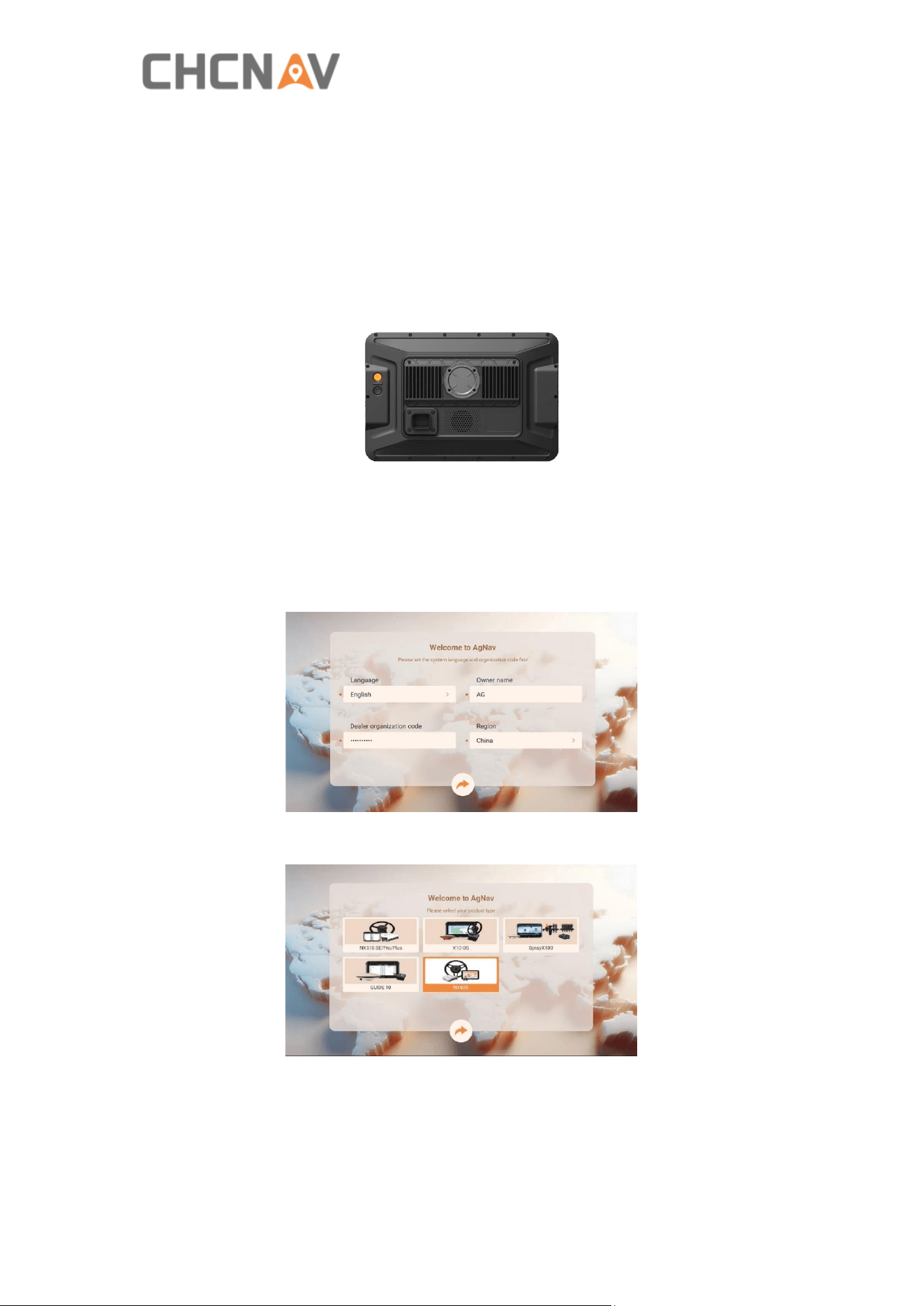
5.2 Boot guide
1. On this page, select the language and region, then enter the username and dealer
organization code (obtained from the local dealer).
2. Select the correct automatic steering system: NX600.
5.3 Software registration
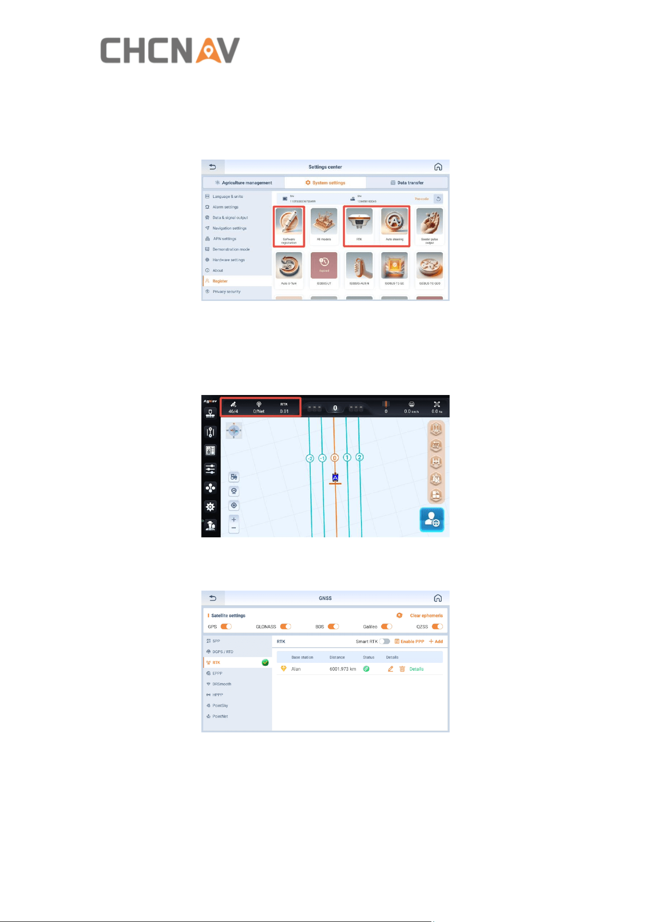
Navigate to [Settings center - System settings - Register] to check whether the
20
software is registered. It is necessary to register for Software registration, RTK, and
Auto steering at least. Please contact CHCNAV technicians when it shows that they
are Not activated and provide the tablet SN to get the online registration. Advanced
U-Turn, ISOBUS, PointSky and other features require a paid subscription.
5.4 GNSS settings
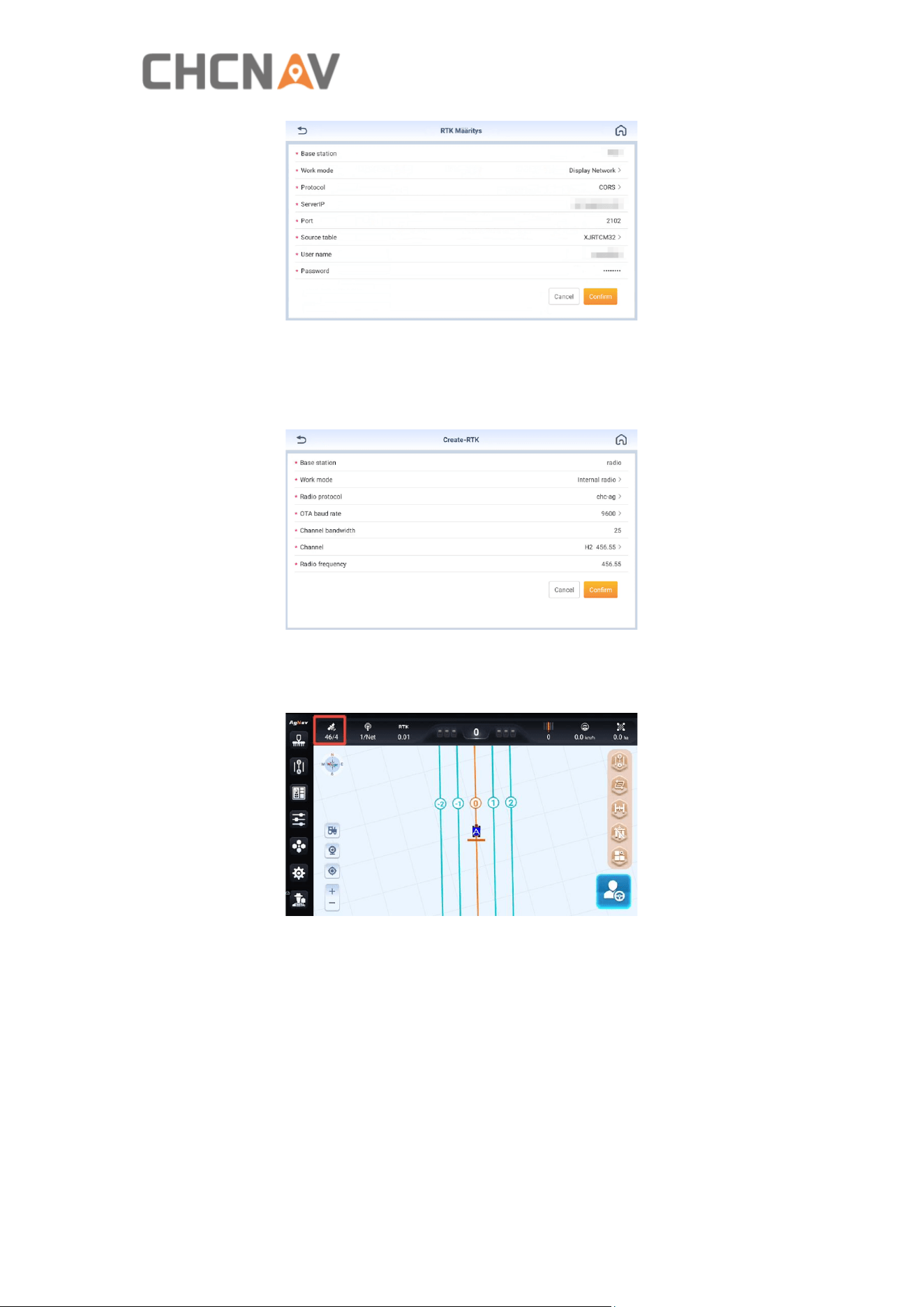
1. Tap the satellite status icon on the main interface to enter the GNSS settings
screen.
2. Select CORS, radio, PPP, or other positioning modes based on the actual working
environment.
3. If the work area has network access and CORS coverage, click Add, select Tablet
Network/Controller Network, then enter the CORS account information and log in.
21
4. If the work area has no network but there is a radio base station, click Add, select
the Internal radio, then enter the same configuration information as the base station
to complete the connection.
5. Return to the main interface to check the status bar. When the GNSS solution is
getting Fix with number 4, the system is ready to use.
5.5 Vehicle settings
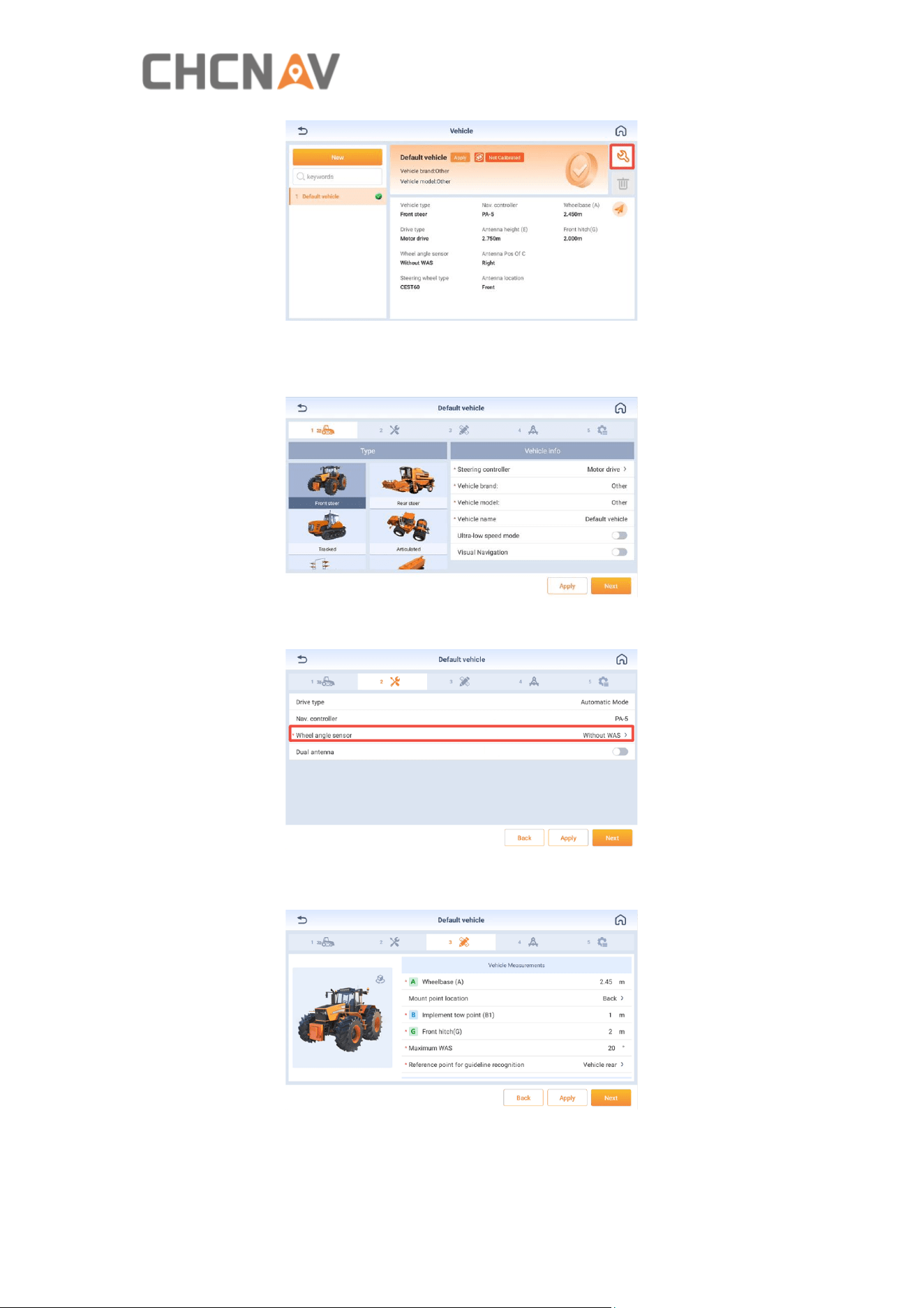
1. Navigate to [Settings center - Agriculture management - Mechanical calibration -
Modify] to set the vehicle parameters.
22
2. Select the vehicle type and input the vehicle information. (Note: If the working
speed is between 0.1 and 1 km/h, ultra-low speed mode must be activated.)
3. Select sensor mode, default to WAS mode.
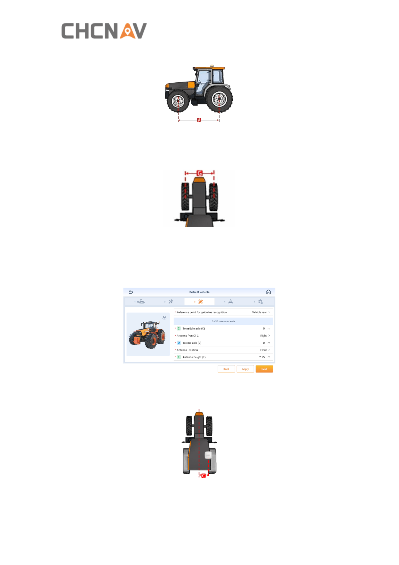
4. Measure and record vehicle parameters according to the diagram.
Wheelbase(A): Measure the distance between front wheel rotation axis and rear
23
wheel rotation axis. Note that the tape measure needs to be parallel to the ground.
Implement Tow Point(B): Use the default value of 0 and it will be used in the futural
development.
Front hitch(G): Measure the distance between the two front wheels.
Maximum WAS: The default is 25, which represents the maximum angle the vehicle
can turn.
Reference point for guideline recognition: You can select between Vehicle head and
Vehicle rear.
To Middle Axle(C): If the receiver is not mounted on the central axis, measure the
distance from the receiver to the central axis. If it is on the central axis, enter 0.
Antenna Pos of C: Fill in according to the receiver position.
24
To Rear Axle(D): Measure the horizontal distance from the antenna center to the
rear wheel center. (It is convenient and accurate to project the antenna center and
the rear wheel center onto the ground, then measure it.)
Antenna location: The relative position between the antenna center (the position of
the antenna center should be referred to the blue indicator) and the rear axis. Select
Front if the antenna is in front of the rear axis, select Rear if the antenna is behind
the rear axis.
Antenna height(E): Measure the vertical height from the antenna center to the
ground.
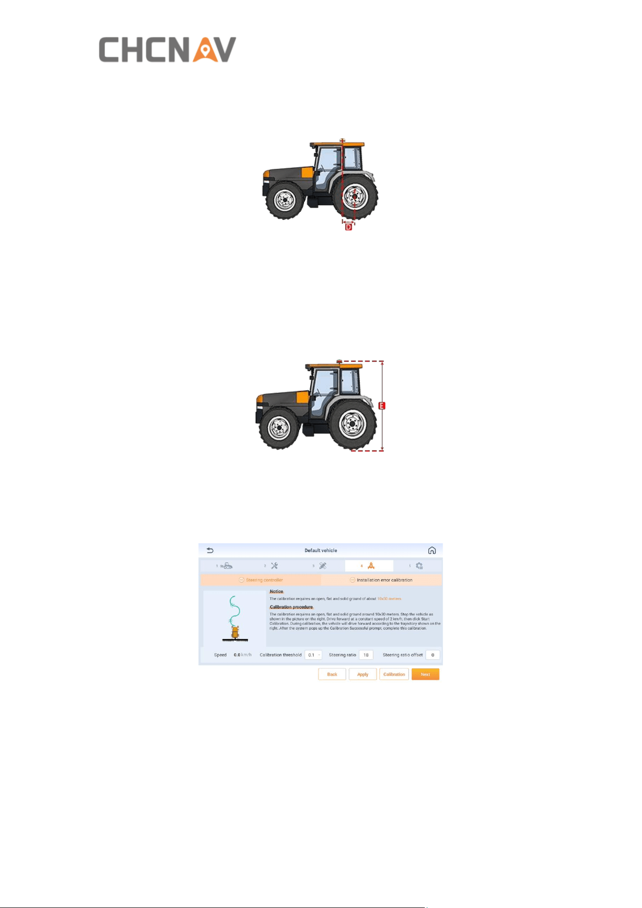
5.6 Calibration
5.6.1 Steering calibration
1. The calibration requires an open, flat and hard ground about 10*30 meters.
2. Keep the vehicle running at 2km/h and click [Start]. During the process, the
steering wheel will turn automatically.
3. When the screen shows “Waiting for calibrating…”, around 2 minutes later, the
calibration will be successful.
25
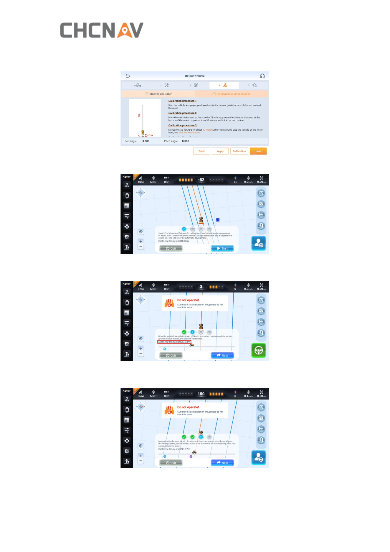
5.6.2 Installation error calibration
1. Stop the vehicle at a proper position close to the current guideline and click start.
2. Drive the vehicle forward at the speed of 2km/h, stop when the distance displayed
at the bottom of the screen is more than 30 meters, and click the Next button.
3. Manually drive forward for about 10 meters, then turn around, Stop the vehicle on
the line in front, and click the Next button.
4. Drive the vehicle forward at the speed of 2km/h again, stop when the distance is
less than 1 meter from the starting point, and click the End button. Wait for the
26
system to automatically complete the calculation.
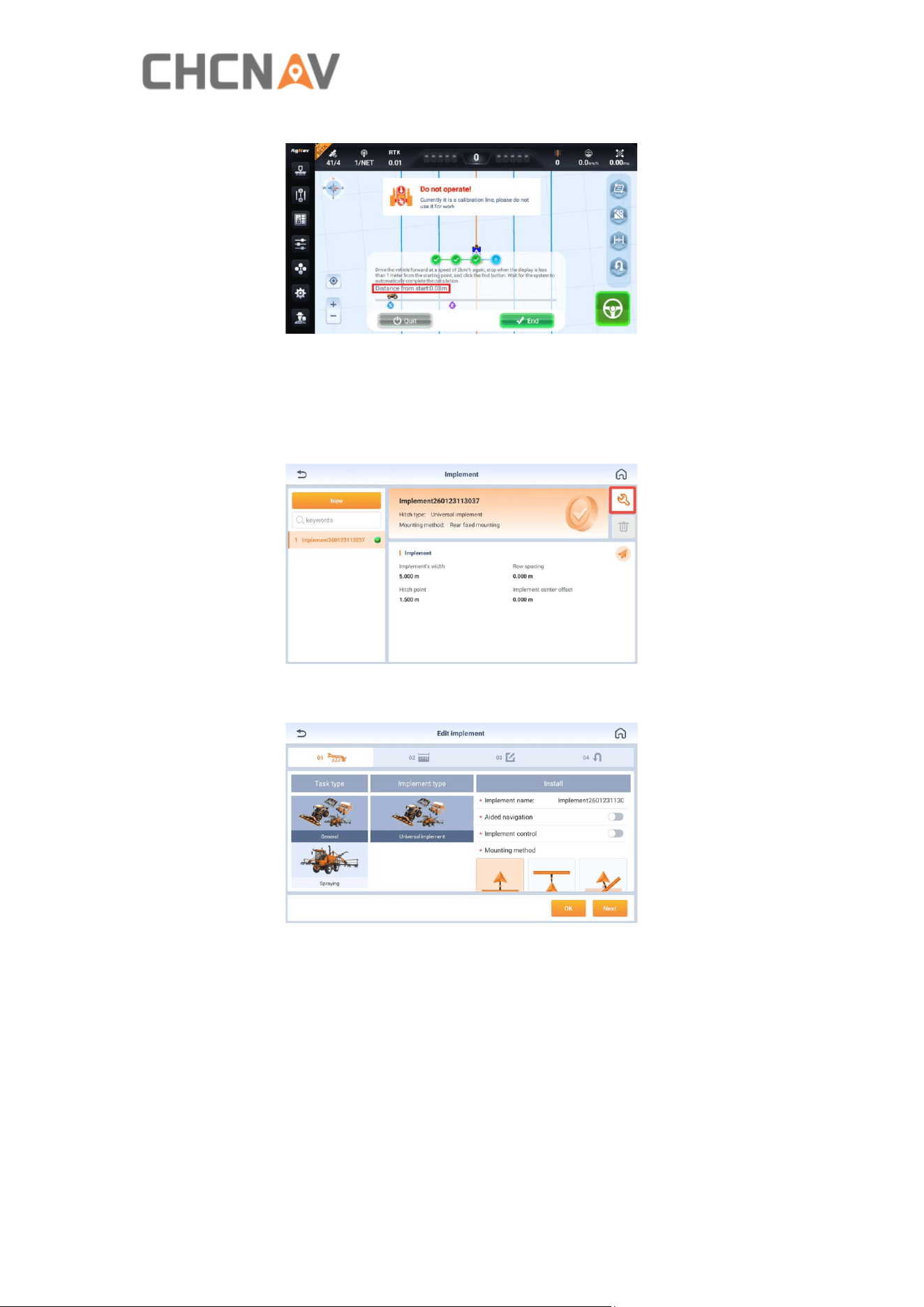
5.7 Implement settings
1. Go to [Setting center - Agricultural management - Implement - Modify] to the
implement.
2. Selecting implement type and mounting method.
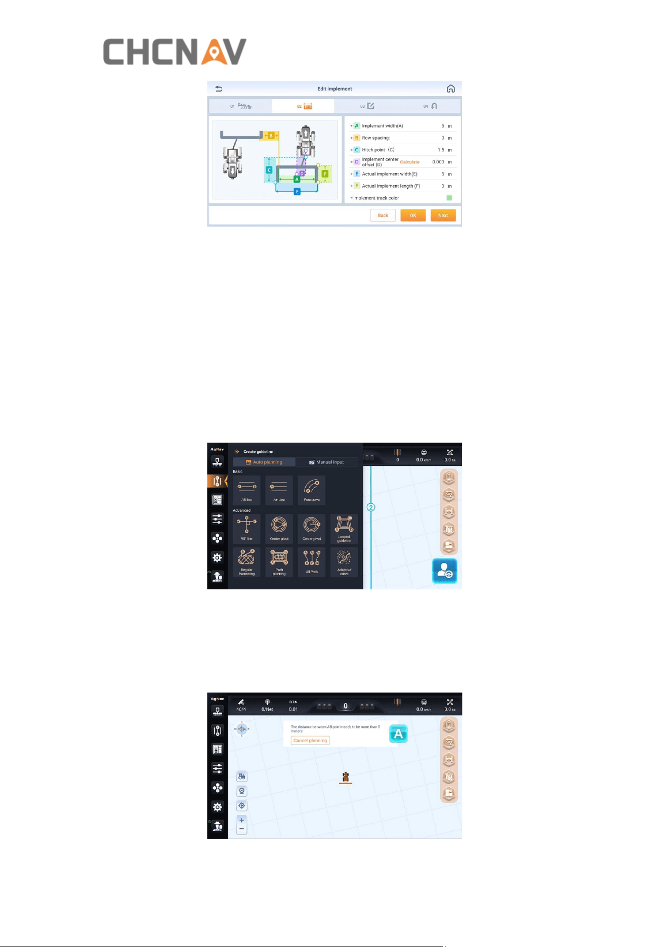
3. Input the implement parameters. The following 4 parameters must be entered
correctly.
27
Implement width: The width of the implement, and the default value is 5m.
Row Spacing: The distance between two rows, and the default value is 0m.
Hitch Point: The distance from hitch point to implement, and the default value is
1.5m. The current algorithm does not use this value, so it has no practical
significance.
Implement center offset: The offset from implement center to vehicle center.
5.8 Basic guidelines
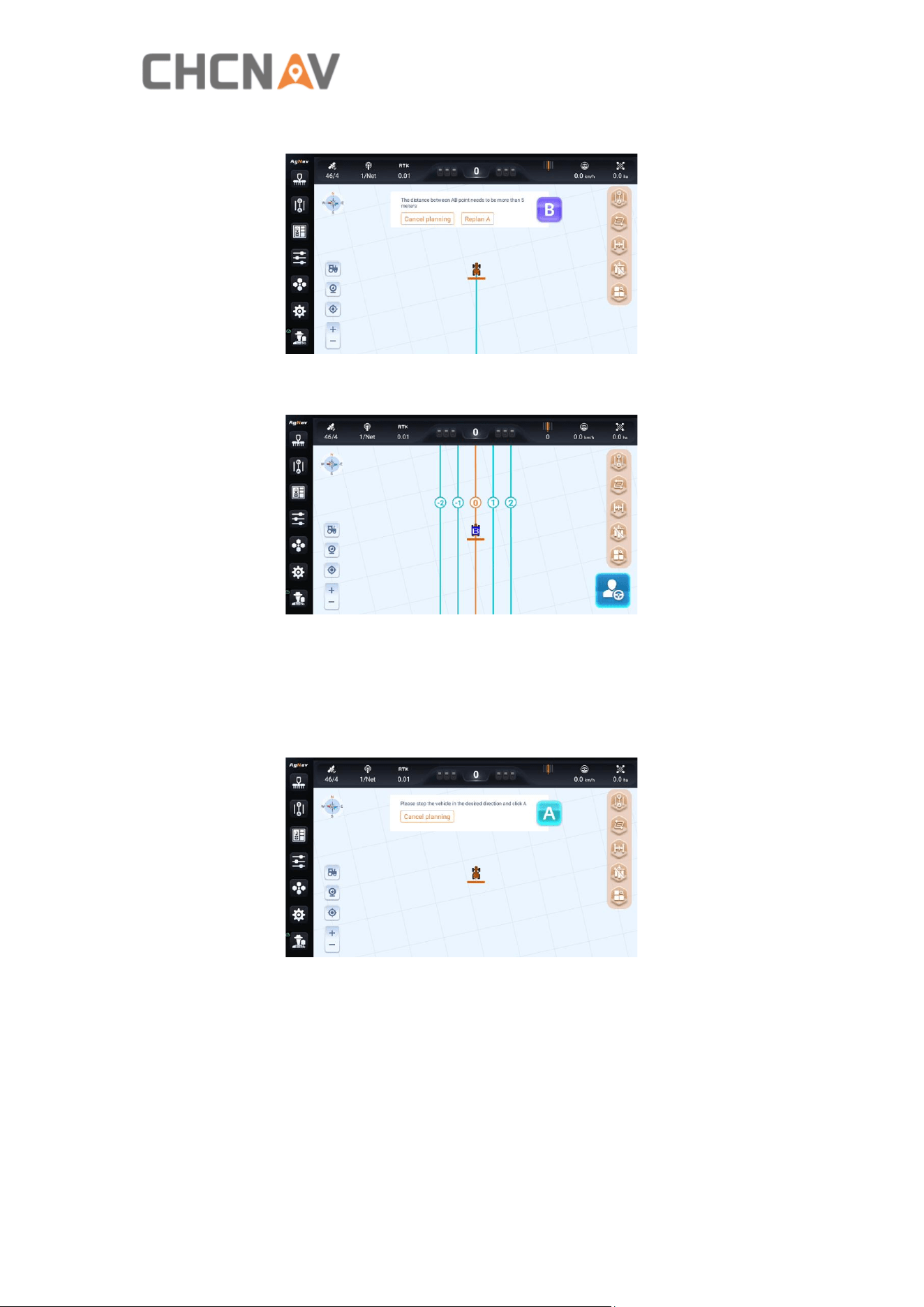
Click the Guideline button on the main interface and select the guideline to be
created.
5.8.1 AB line
Create a straight line through two points.
1. Click A in the current location.
28
2. Drive to another end of the field and click B.
3. New AB line is created successfully.
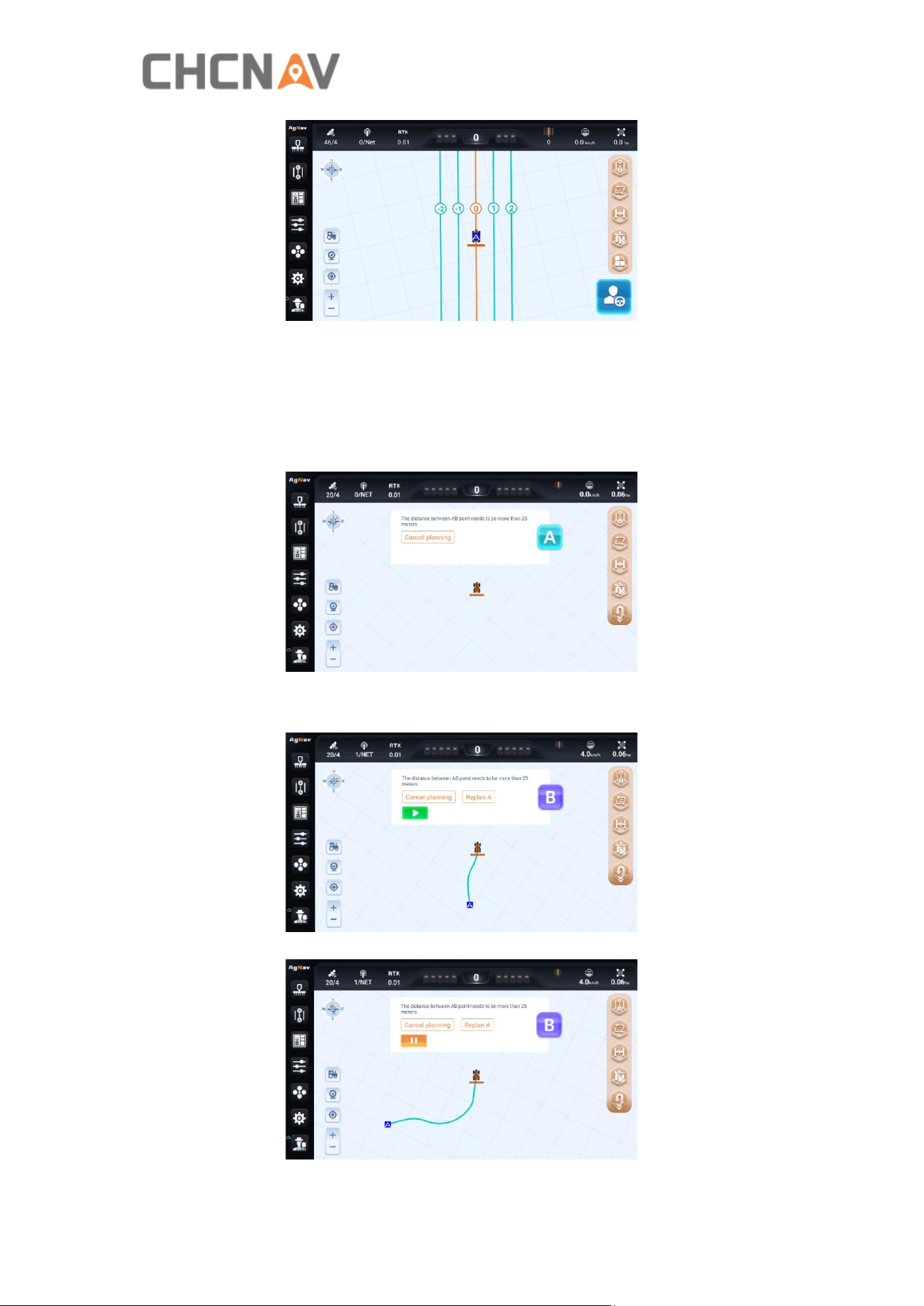
5.8.2 A+ line
Create a straight line through one point and the receiver's heading.
1. Click A in the current location.
2. New A+ line is created successfully.
29
5.8.3 Free curve
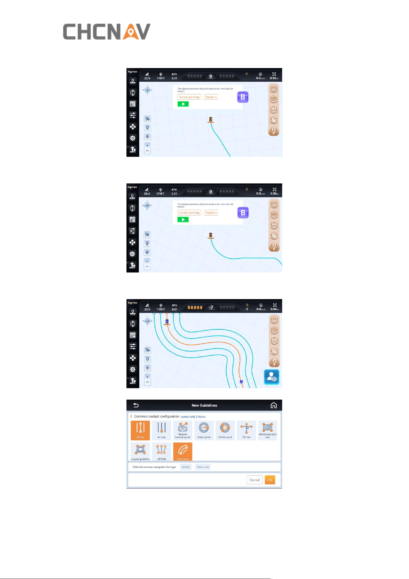
Create curves or combinations of curves and straight lines based on real-time paths.
1. Click A to start the curve.
2. Click [Start] to create the straight line.
30
3. Click [Pause] to continue creating the curve line.
4. Click B to finish the Free curve creation.
5. New Free curve is created successfully.
31
5.9 Engage and disengage automatic steering
Click to start automatic steering after completing the above steps.
After completing the task, stop the vehicle first, then press to disengage
automatic steering.
5.10 Power Off
Press and hold the orange button for 3 seconds to power on the system.

32
6 Maintenance
1. To ensure the normal operation and service life of the equipment, please
maintain the equipment under the instruction of the manual.
2. Please do not disassemble the main components of the system. If necessary,
please contact the CHCNAV after-sales service support_ag@chcnav.com.
3. Please use device under the instruction of user guide.
4. Regularly check each screw, wiring harness and connector of the system, such as
controller fixing screws, angle sensor fixing screws, data cable connectors, etc.
5. Keep the motor clean.
6. Maintain the environment in which the motor is used. Please do not wrap
materials such as cotton cloth and dustproof film on the motor.
7. Before starting the work, check whether the transmission device is flexible;
whether the concentricity of the coupling is standard; the flexibility of the gear
transmission.


FCC ID:SY4-A02078
FCC Caution:
This device complies with part 15 of the FCC Rules. Operation is subject to the following two
conditions: (1) this device may not cause harmful interference, and (2) this device must accept any
interference received, including interference that may cause undesired operation.
Any changes or modifications not expressly approved by the party responsible for compliance could void
the user's authority to operate the equipment.
NOTE: This equipment has been tested and found to comply with the limits for a Class B digital device,
pursuant to Part 15 of the FCC Rules. These limits are designed to provide reasonable protection against
harmful interference in a residential installation. This equipment generates, uses and can radiate radio
frequency energy and, if not installed and used in accordance with the instructions, may cause harmful
interference to radio communications. However, there is no guarantee that interference will not occur in a
particular installation.
If this equipment does cause harmful interference to radio or television reception,which can be
determined by turning the equipment off and on, the user is encouraged to try to correct the interference
by one or more of the following measures:
-- Reorient or relocate the receiving antenna.
-- Increase the separation between the equipment and receiver.
-- Connect the equipment into an outlet on a circuit different
from that to which the receiver is connected.
-- Consult the dealer or an experienced radio/TV technician for help.
To maintain compliance with FCC’s RF Exposure guidelines, This equipment should be installed and
operated with minimum distance 20cm between the radiator and your body: Use only the supplied
antenna.