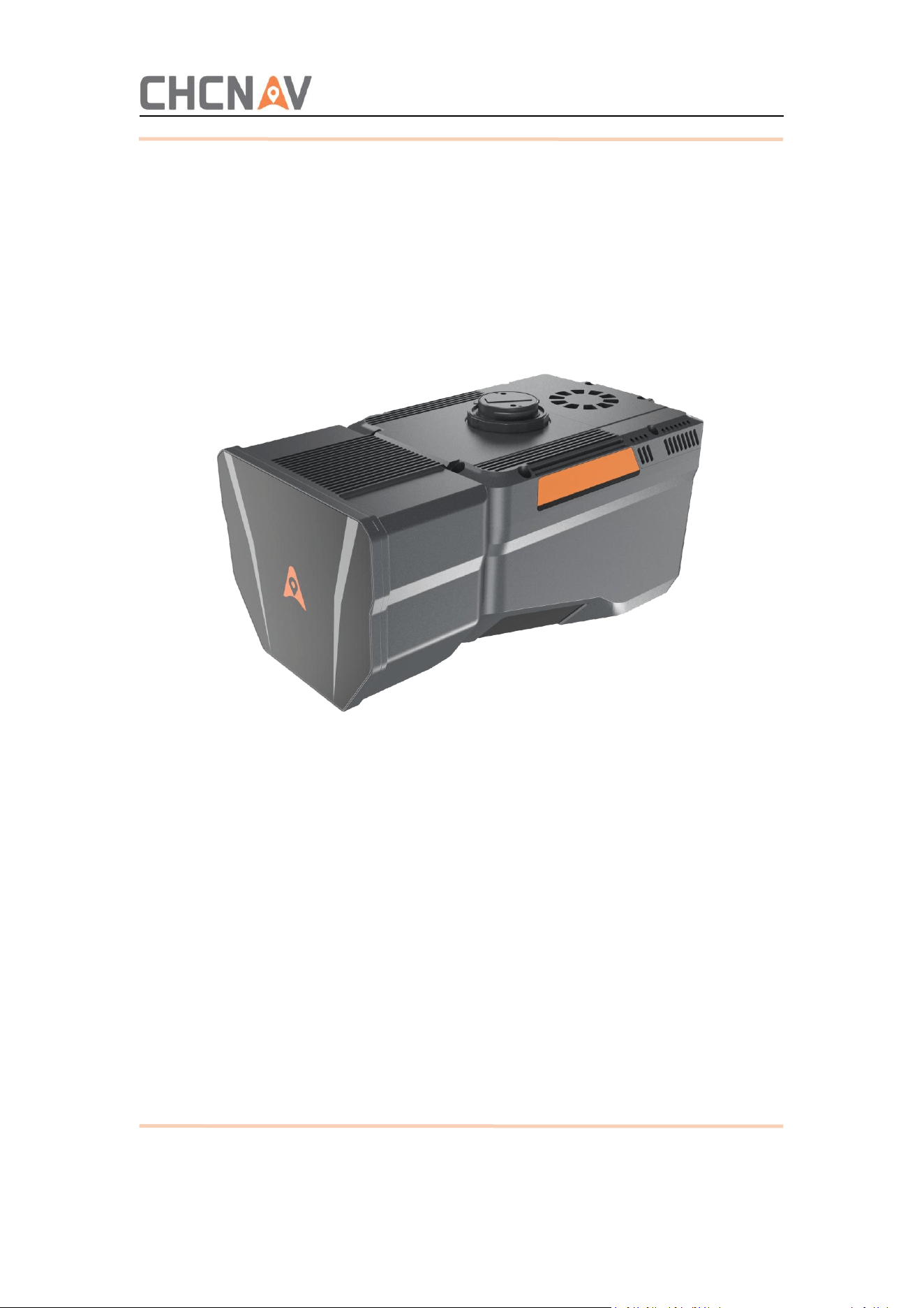
AA6D Survey System User
Manual
Shanghai Huace Navigation Technology Ltd.

1
Table of Content
Preface...........................................................................................................................1
1 Reading Tips................................................................................................................1
1.1 Symbol description...........................................................................................................1
1.2 Disclaimer.........................................................................................................................1
2 Product Introduction.................................................................................................. 1
2.1 Device Specifications, Dimensions, and Interface Definitions.........................................2
2.2 Product Parameter...........................................................................................................3
2.2.1 System Parameter.....................................................................................................3
2.2.2 Range Capability........................................................................................................4
3 Product Usage.............................................................................................................4
3.1 Previous Preparation........................................................................................................4
3.2 Device Attachment...........................................................................................................5
4 Data Copy....................................................................................................................7
4.1 Introduction to Hard Disk Data........................................................................................ 7
4.2 Data Copy......................................................................................................................... 8
4.3 Data Clear.........................................................................................................................8
5 Workflow of Data Processing..................................................................................... 9
5.1 Create a New Project....................................................................................................... 9
5.2 POS Resolving.................................................................................................................10
5.2.1 Base Station Data Preparation................................................................................10
5.2.2 POS Resolving..........................................................................................................10
5.2.3 POS Quality Control.................................................................................................12
5.2.4 Solution Region Selection....................................................................................... 12
5.3 Data solve.......................................................................................................................13
5.3.1 Pictures processing..................................................................................................14
5.3.2 Point Cloud Processing............................................................................................14
5.3.3 Point Cloud Coloring Settings..................................................................................15
5.3.4 Generate Results.....................................................................................................16
5.3.5 Achievements..........................................................................................................16
5.3.6 Export Results..........................................................................................................16

2
6 Precautions for Daily Use..........................................................................................18
6.1 Service Environment...................................................................................................... 18
6.2 Daily Usage Guidelines...................................................................................................18
6.3 Equipment Transportation.............................................................................................19
6.4 Device Storage................................................................................................................19

1
Preface
This manual is designed to help users better utilize the AA6D survey system from Shanghai
Huace Navigation Technology Co., Ltd. (hereinafter referred to as " CHCNAV ").
If you have any questions about this manual, please contact us at 021-51508100 for professional
consultation and assistance.
CHCNAV reserves the right to modify product status and user manuals without prior notice.
All copyrights and final interpretation rights of this document and its attachments are owned by
CHCNAV.
1 Reading Tips
1.1 Symbol description
Prohibit
Warning
I Important Notes
Operation and Usage Tips
1.2 Disclaimer
Customers must use and maintain the equipment in accordance with the user manual. We shall
not be liable for any equipment lifespan reduction or malfunction caused by improper use or
maintenance. All related repair and maintenance services will be charged at standard rates.
We shall not be liable for any instrument damage caused by improper logistics handling during
transportation.
If the customer disassembles or reassembles the equipment without following the manufacturer's
instructions during its use, resulting in damage, we shall not be held liable.
2 Product Introduction
The AA6D surveying system is specifically designed for vehicle-mounted mode and is widely used
in vehicle-based operations such as urban surveying.
2
2.1 Device Specifications, Dimensions, and Interface Definitions
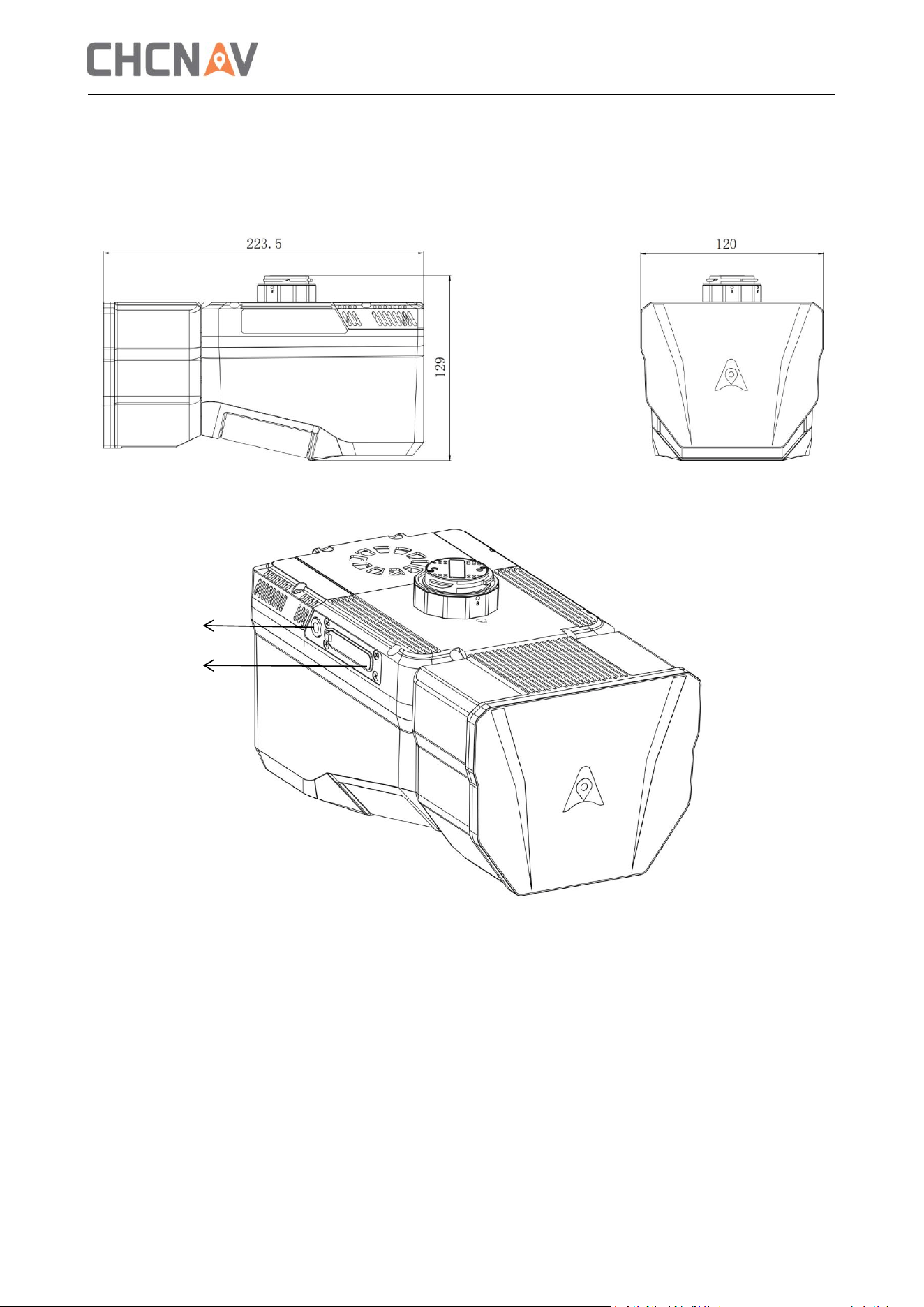
The weight of the host is 1.85 kg.
The dimensions (223.5×120×129mm) are shown in the figure below:
Device interface and indicator light description:
1. Card slot for storage 2. Indicator light
②
①
3
2.2 Product Parameter
2.2.1 System Parameter
System
parameter
System accuracy
5 cm H, 5 cm Z
Weight
1.85kg
Size
223.5×120×129mm
Service voltage
24V (wide voltage range: 17-30V)
Data storage
512GB
Transmit speed
200MB/s
Work temperature
-20
℃
~+50
℃
Typical power
50W@300KHz,200I/s
Max.power
60W
IP level
IP64
Laser
measurement
system
range
10~2100m
Maximum point frequency
2 million points per second
Line speed
Up to 400 lines per second
FOV
90°
Maximum returns
16
MTA
7
range
accuracy/repeatability
15mm/5mm@150m
Position
and orientation
system
GNSS
GPS:L1,L2,L5
GLONASS:L1,L2
BEIDOU:B1,B2,B3
GALILEO:E1 E5a E5b
Position accuracy after
post-processing
Pitch/roll angle: 0.006° (post-processing, 1σ);
yaw angle: 0.015° (post-processing, 1σ);
4
Post-processing position
accuracy
Horizontal: 1 cm + 1 ppm;
Vertical: 1.5 cm + 1 ppm;
IMU update rate
500Hz
Camera
parameters
Resolution
26MP * 2 (6252 * 4168)
Focal length
16mm
Sensor size
Semi-frame
Field of view
110°
Minimum photo interval
1s
2.2.2 Range Capability
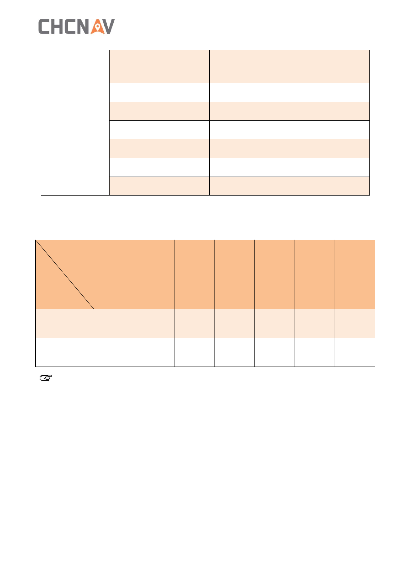
The ranging capability of different frequency points is shown in the table below:
100k
200k
300k
500k
1000k
2000k
1000k
low
power
Reflectivity ρ ≥
10%
960m
870m
750m
640m
460m
320m
250m
Reflectivity ρ ≥
80%
2100m
1800m
1700m
1450m
1000m
525m
500m
Note:
The point frequency is rounded to the nearest integer, with the actual point frequency slightly
exceeding this value.
3 Product Usage
3.1 Previous Preparation
1. The base station must be pre-installed, with its coordinates measured and instrument height
recorded. The base station should then be powered on and static data logged.
Point
frequency
Reflectivity
5
3.2 Device Attachment
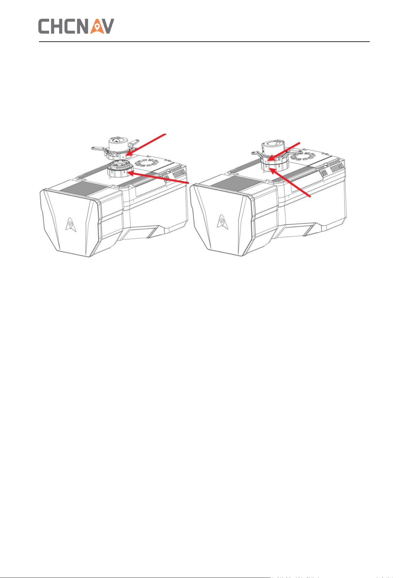
(1) Align the white dot on the device's interface with the red dot on the mounting board, then
connect the device.
(2) Rotate the device clockwise with the right hand to align its red dot with the mounting board's
red dot, completing the installation.
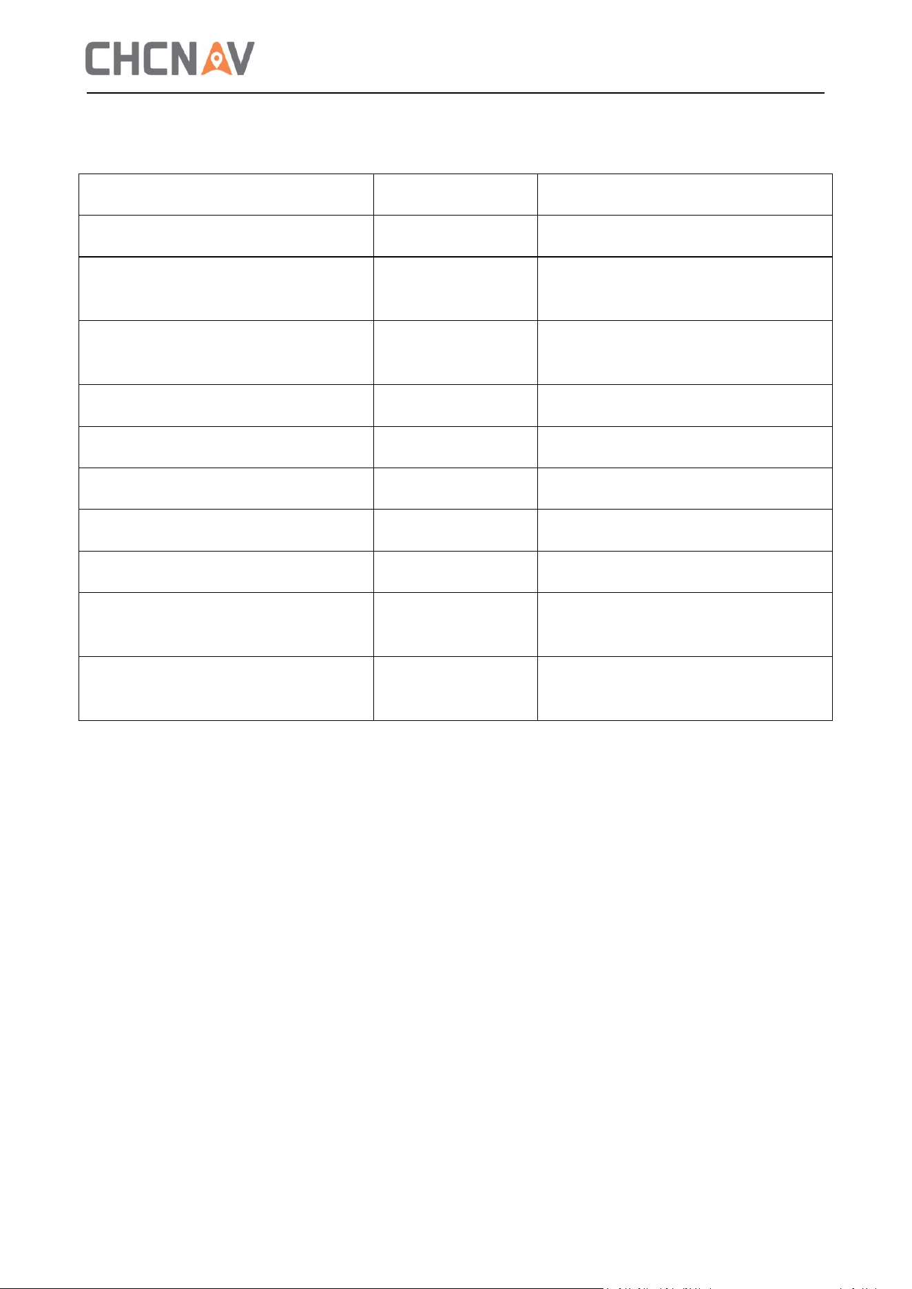
2. After the device is installed, The AA6D will automatically power on. Wait about ten seconds, and
the device's indicator light will start blinking, indicating successful power-up.
Power on and wait 60-70 seconds until the device indicator light stays on, indicating initialization
completion. At this point, you can start data collection.
6
Different states of AA6D indicator light
Indicator & Buzzer Status
Device status
Device Operating State
Steady off
Power off
No power
Flashing at 5Hz
Power on, not
ready
Satellite not locked, INS not
synchronized
Steady on
Initialization
complete
Satellite locked, INS synchronized
Two flashes, one off
Project started
INS/GNSS data collection
Green light slow flash (2 seconds)
Data collection
Point cloud/image data collection
Steady red
Abnormal
Device operating abnormally
Red and green alternating flash
Firmware update
Updating firmware
Buzzer sounds once for 1 second
Device startup
Device just powered on
Buzzer sounds for 1 second at
1-second intervals
Abnormal
Device faulty, unable to operate
Buzzer sounds for 2.5 seconds at
2.5-second intervals
License expired
Device unlicensed or license expired
7
4 Data Copy
4.1 Introduction to Hard Disk Data
To access the storage card in the device, connect it to the computer using the included card reader.
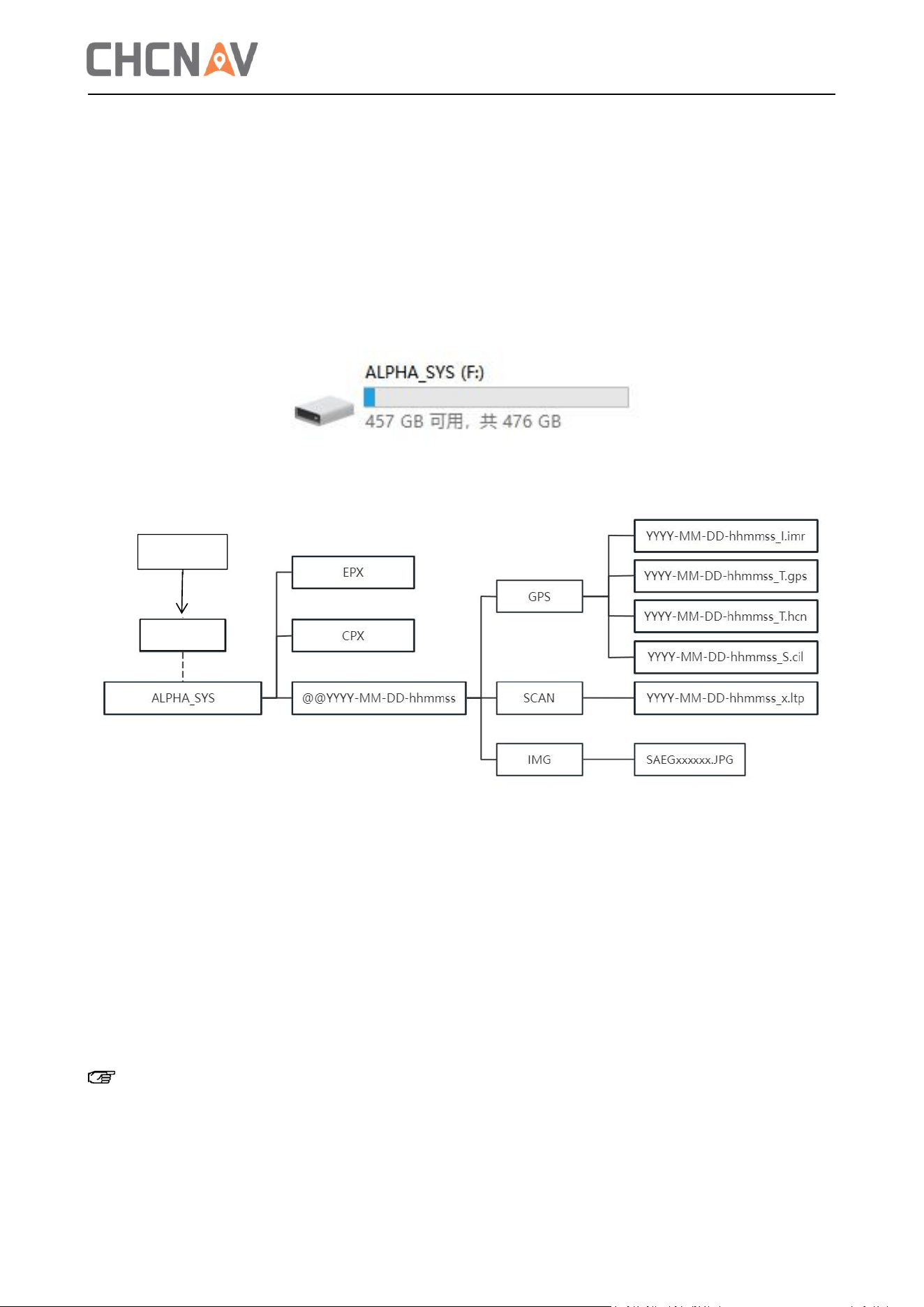
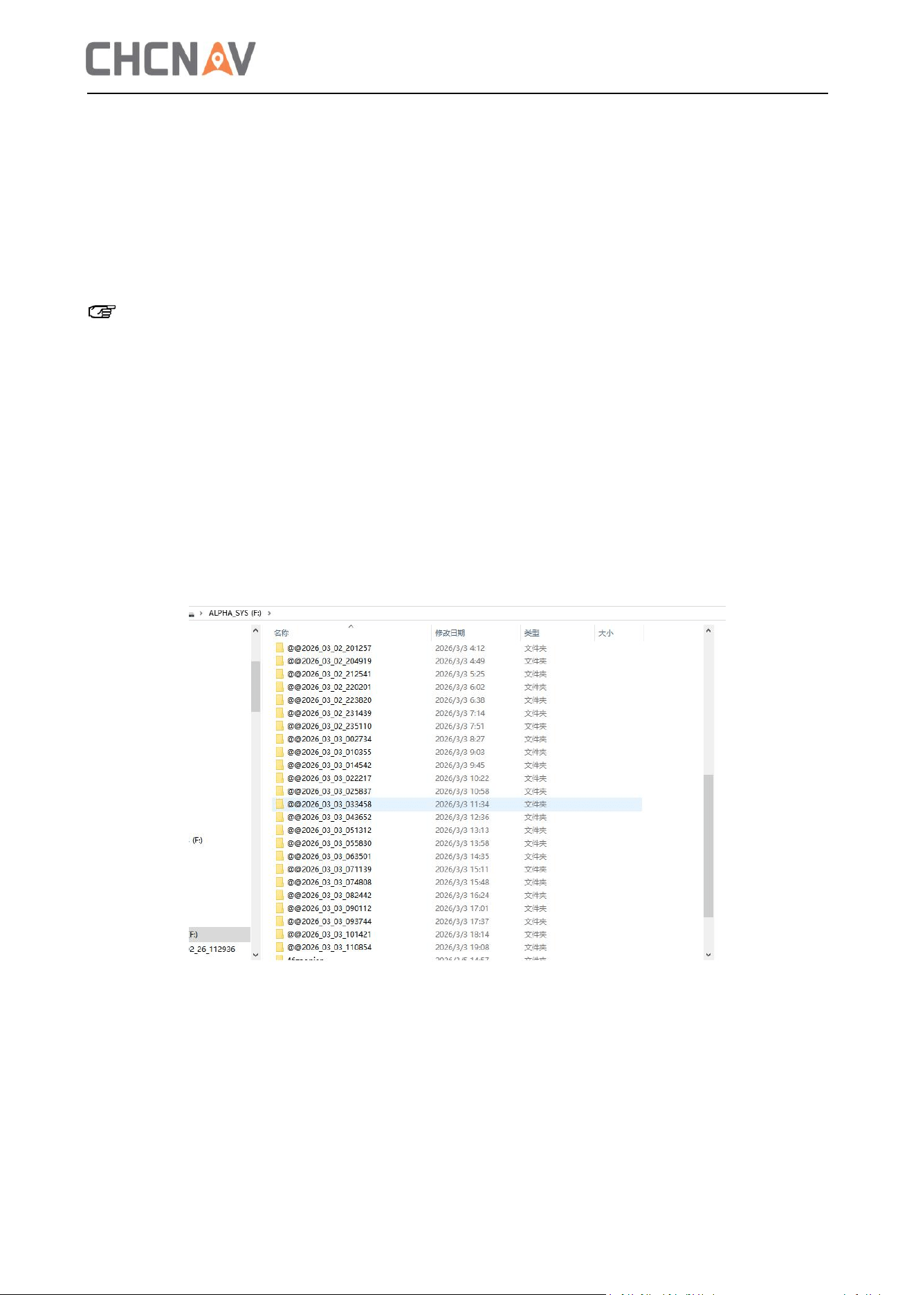
The computer will then display the ALPHA_SYS drive letter. The AA6D device has 512GB of memory,
as shown in the figure below.
Data organization diagram
File Specification :
(1) The ALPHA_SYS contains three folders: EPX, CPX, and the project folder starting with @@.
(2) A folder named after the collection time, storing all collection project information, including:
①GNSS observation data (xxxxxx_T.gps and xxxxxx_T.hcn)
② Inertial navigation data (xxxxxx_I.imr)
③ Lidar and camera control commands and interaction data (xxxxxx_S. cil)
④ Laser data (xxxxxx.ltp) file
⑤ Calibration parameter files (CPX for camera calibration, EPX for laser calibration).
Note:
After the data copy is complete, eject the data card from the computer and unplug the data
copy cable. If the data card is not ejected, it may be damaged.
AA6D
PC
8
The EPX and CPX folders are parameter files provided by the manufacturer. You cannot delete
this file, as it is required for data copying.
4.2 Data Copy
1. Confirm that the ALPHA_SYS drive letter appears on the computer.
2. Simply copy the project you need to transfer to your local computer.
Note:
Keep your computer and card reader stable during data copying to prevent interruptions.
Do not use the cut function to copy data to avoid losing your backup.
Copy the project file to an English path and do not contain the space.
4.3 Data Clear
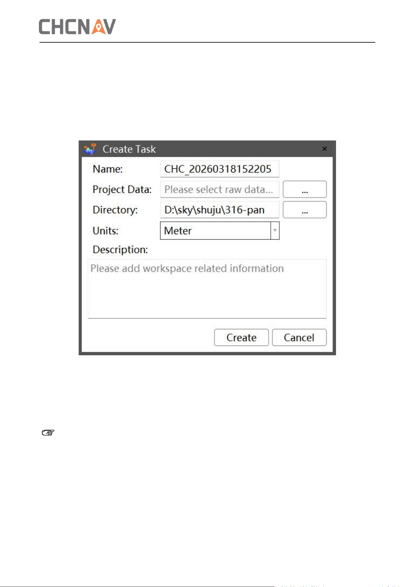
When the ALPHA_SYS hard drive has less than 10% remaining capacity or the capacity cannot meet
the current project requirements, data cleanup is required.
Open the ALPHA_SYS drive, select the project folder starting with @@ to delete, and right-click to
remove. Do not delete other system configuration folders.
9
5 Workflow of Data Processing
5.1 Create a New Project
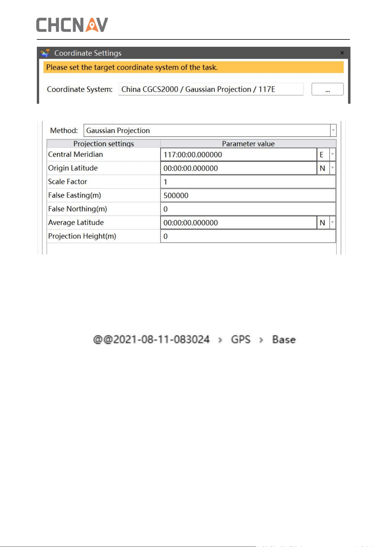
1. Open CoPre software, click "Engineering Management-> New", and the task creation dialog box
will appear.
Task name: Name of the new workspace;
Engineering data: Copy the original engineering data (from the @@+ collection time folder) using
the copy tool.
Task path: the location for intermediate and final data.
Unit: Default is meters.
Note: The original project and CoPre task do not support non-English paths or spaces. The
original data should be stored in an English path. When creating a new CoPre task, use an English
name and storage path.
2. After clicking "Create", the coordinate system setup window will appear. Click the "..." button on
the right side of the coordinate system to open the setup window. Set the corresponding
coordinate system as needed, then click "OK" to complete the new project.
10
5.2 POS Resolving
5.2.1 Base Station Data Preparation
Place the base station observation file (either *.HCN format or a standard Rinex 3.02 observation
file) into the @@YY-MM-DD-hhmmss/GPS/Base folder.
5.2.2 POS Resolving
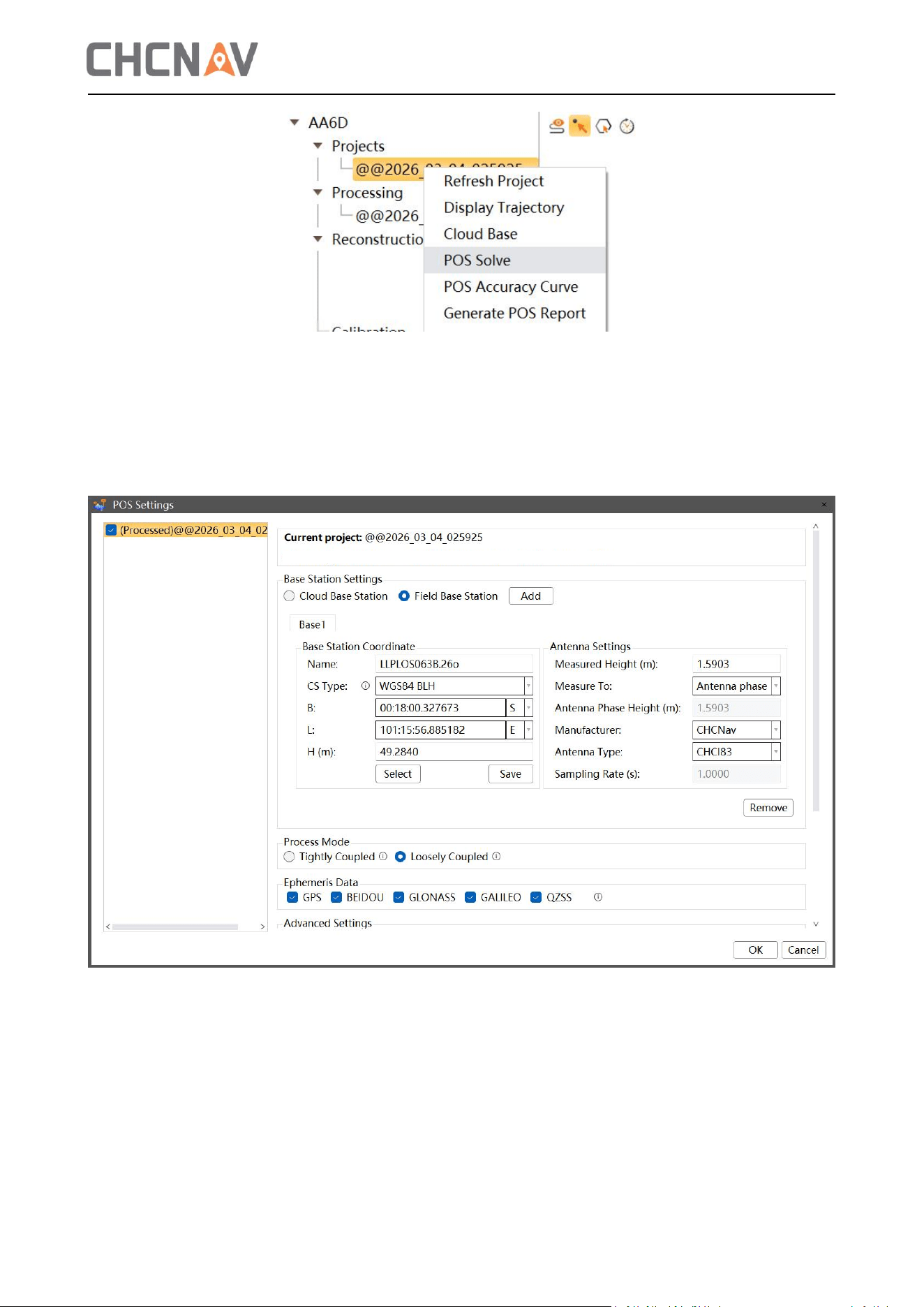
Select the engineering file for POS calculation. Right-click to open the options. Choose 'POS
Calculation' to open the POS calculation window, as shown below:
11
If the static base station file (HCN) is placed in the Base folder under the GPS folder, the system will
automatically detect the base station file and read the corresponding antenna elevation. You need
to manually enter the measured coordinates into the base station coordinates (geodetic
coordinates in degree, minute, and second format).
In the 'More' option at the bottom right, you can configure the Ephemeris Data for calculation. As
shown in the figure below.
After setting the base station coordinates and antenna type, click 'Confirm' to start POS
calculation.
After POS calculation, the task management interface displays a progress bar showing the
calculation percentage, while the software's output panel shows relevant POS calculation details,
as shown in the figure below.
12
5.2.3 POS Quality Control
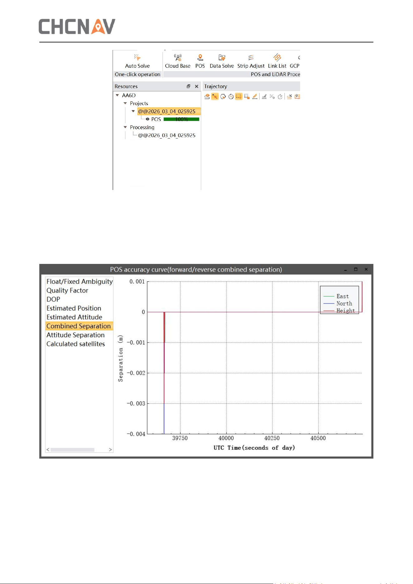
After POS calculation, right-click the engineering node and select 'POS Accuracy Curve' to evaluate
data quality through multiple metrics. Key reference parameters include forward/reverse positions
and the number of satellites involved in calculations. The ‘Combined Separation should not exceed
1cm, as shown in the figure below.
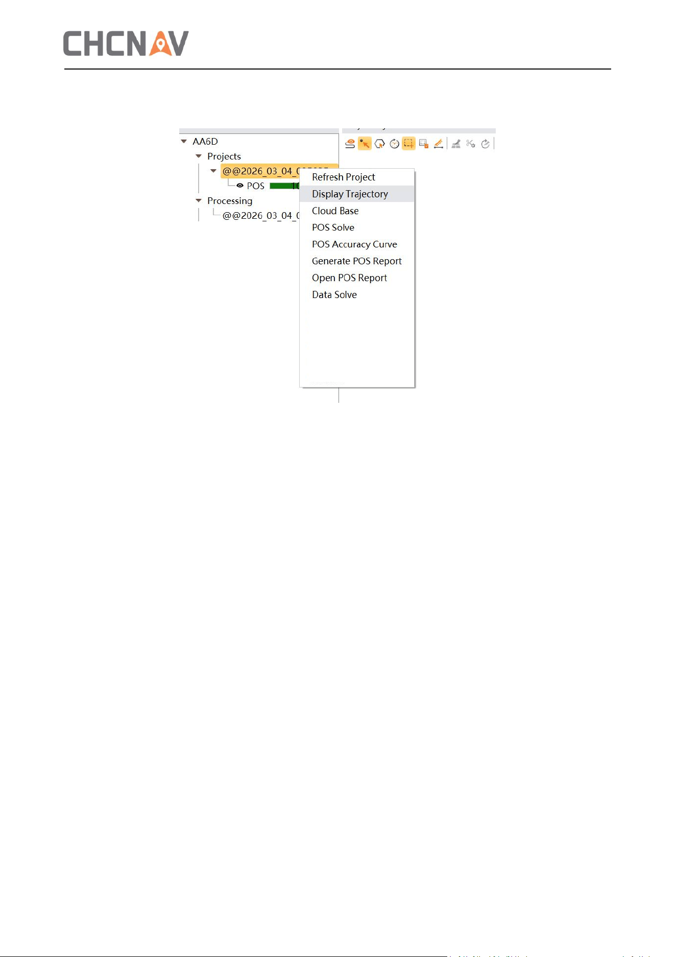
5.2.4 Solution Region Selection
After POS calculation, right-click the engineering file and select 'Display Trajectory' with the left
click to view the POS trajectory.
13
CoPre automatically selects trajectory data from long straight lines. If there are calculation areas
with recognition errors, hover over the corresponding trajectory to right-click and cancel the
selected POS segment. Alternatively, right-click to cancel all POS segments and manually select the
trajectory points.
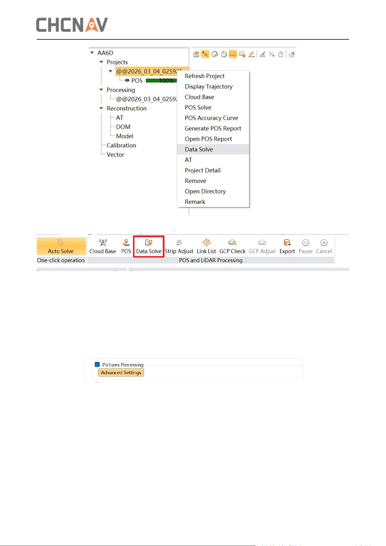
5.3 Data solve
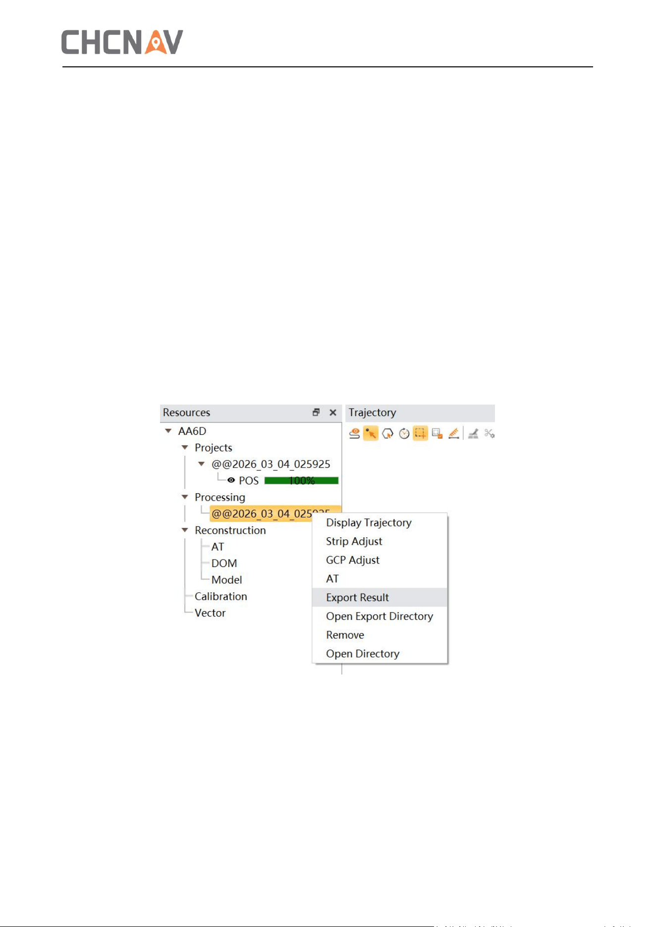
After selecting the path, click ‘Data solve’ in the ‘Processing’ window, or right-click the project and
select ‘Data Solve’ as shown below.
14
5.3.1 Pictures processing
Pictures processing: If the project contains image data, select 'Pictures processing' to enable CoPre
to automatically match and generate corresponding photo POS files.
Time delay: Default is 0 seconds. You can set this if the photo has a time delay.
Write EXIF information: Not selected by default. When selected, it writes location, POS, and other
information to the organized photo file, as shown below:
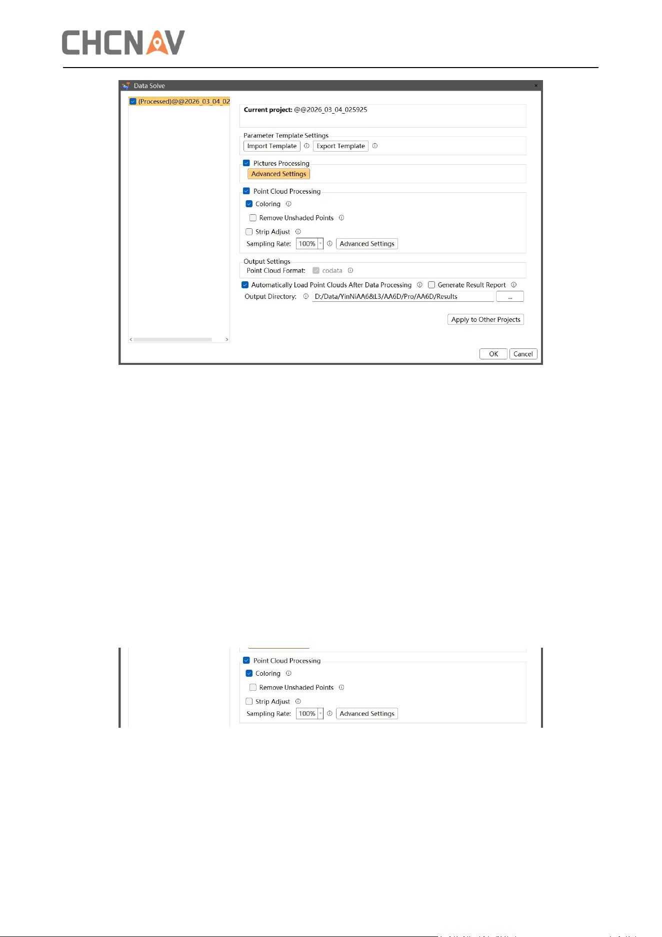
5.3.2 Point Cloud Processing
This part primarily generates point cloud data, including filter settings, sampling rate, and coloring
settings, as shown in the figure below.
15
Click the ‘Advanced Settings’ button to access the filter setting interface. The settings primarily
include MTA filter, Circle Noise Filter, FOV Filter, 3D Distance Filering, Intensity Filtering, Noise
Filtering and 2D Distance filtering.
The filtering options are usually selected as Intensity filtering, Noise filtering and 2D Distance
filtering.
Intensity filtering: Filters out points outside the range based on grayscale values. The default range
is 800-65535.
Noise filtering: Set the distance threshold parameter to filter out noise points.
5.3.3 Point Cloud Coloring Settings
Point cloud coloring generates a colored point cloud with RGB information based on the point
cloud and photo. This option is enabled by default. When selected, the point cloud will be
rendered as a colored point cloud. As shown in the figure below:
Point cloud coloring parameters: default range 0-65535;
Filter Tower Shadow: This option resolves the issue of tower colors being assigned to the ground
during power line data coloring.
16
5.3.4 Generate Results
After completing the parameter settings, click OK to generate the result. Once the processing
successful, the software dialog will indicate that all data processing is complete, and the 3D View
will display the result project.
5.3.5 Achievements
Select a project under the ‘Processing’ node, right-click to display the trajectory, and the result
trajectory will load into the trajectory view. Click two points on the result trajectory or hold the left
mouse button to select a box, and the point cloud corresponding to the selected trajectory will
load into the point cloud view. You can choose the rendering mode in 3D view to browse the point
cloud.
5.3.6 Export Results
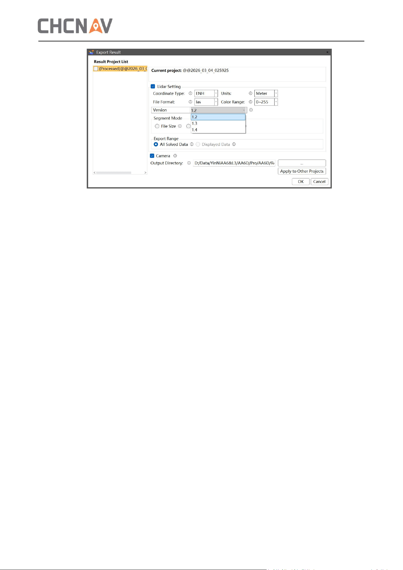
After verifying the point cloud's data quality, export the results if meet the requirements. In the
‘Processing’ node, select the project and right-click to export the results. Coordinate types include
ENH/BLH/ENU/XYZ, and supported export formats are (.las/.laz/e57/pts), as shown in the figure
below.
17

18
6 Precautions for Daily Use
6.1 Service Environment
For equipment safety and to avoid excessive noise in point clouds, the device is prohibited
from use during rain, snow, or heavy fog, and must not be operated in windy or dusty conditions.
Do not expose the device and its accessories to extreme temperatures. The operating and
storage temperatures must not be lower than or higher than the specified temperatures in the
specifications.
When transferring products from a cold environment to a warm one, condensation may occur
on certain components inside the scanner due to moisture. To prevent this, it is recommended to
place the scanner in a sealed plastic bag before transfer. The device should only be opened after its
temperature has substantially equalized with the external environment and the condensation has
evaporated.
6.2 Daily Usage Guidelines
The AA6D survey system is a sophisticated precision instrument. Proper operation and
maintenance during daily handling, transportation, and storage are essential to ensure optimal
accuracy and prolong its service life.
Key usage considerations include:
Do not disassemble the instrument. If a malfunction occurs, please contact the supplier.
This document serves as a comprehensive guide for the AA6D. Select the appropriate
operation method based on your specific workflow. For any questions, please contact the
supplier's technical support team.
Strictly follow the wiring instructions in the installation manual to connect the equipment.
Regularly inspect structural components for loose screws and connectors, and check for cable
damage. Clean the equipment surface, laser window, and camera lens every 7–10 days using a
cleaning kit, following the steps below:
(1) In a dust-free area, use a mini air blower to remove dust from the laser head, camera lens,
and device body.
(2) Gently wipe the laser window, camera lens, and any gaps with a wet wipe to remove
residual dust, fingerprints, and other contaminants.
(3) Wipe the device body and camera with a damp cloth. A soft towel may be used if
necessary.
Note: Do not use corrosive liquids such as alcohol to clean the device body or non-metallic
camera parts.
Always disconnect power before plugging or unplugging the device.
Protect the instrument from strong impact or vibration.

19
After use, pack the instrument promptly. Ensure both the instrument and its case are dry
before packing.
For continuous extended operation or use in high-humidity environments, consult the Huace
Technology Center for specific precautions. Malfunctions under such special conditions are
not covered by the warranty.
Handle the equipment with care to avoid surface contamination or scratches. Do not sit on the
equipment or its packaging box.
6.3 Equipment Transportation
1. The device is equipped with a dedicated carrying case. During transport or transit, place the
device inside the case and use seat belts or other securing methods to keep the case in a fixed
position. This prevents the case from colliding with the vehicle body and experiencing strong
shocks or vibrations during transit.
2. When transporting the device with other means of conveyance, avoid improper handling by
shipping personnel. Inform the handlers that the device is a precision instrument requiring careful
handling. Affix fragile labels to the case.
3. When shipping the device by courier, use an outer box in addition to the original carrying case.
Fill the gap between the two with shock-absorbing materials such as foam padding.
6.4 Device Storage
1. When not in use, place the device neatly in its carrying case. Store the cases on a workbench or
shelf without stacking them.
2. The storage room should be clean, dry, and well-ventilated. Replace the desiccant inside the
case regularly.

20
CHC Navigation
Building C, 577 Songying Road, Qingpu, District,
201703 Shanghai, China
Tel: +86 21 542 60 273 | Fax: +86 21 649 50 963

