
MiniMAC Maestro
user manual
1
2
6
8
5
4
7
9
3
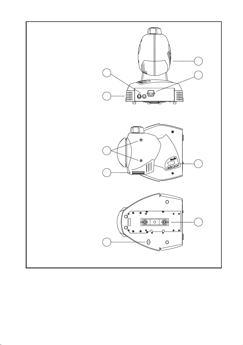
1 data connection
2 base fan
3 head fan
4 AC input & main fuse
5cover locks
6 rear cover
7 control panel
8 eye bolt for safety cable
9 Omega clamp attachment
bracket
©2000-2002 Martin Professional A/S, Denmark.
All rights reserved. No part of this manual may be reproduced, in any form or by any means, with-
out permission in writing from Martin Professional A/S, Denmark.
Printed in Denmark.
P/N 35000091, Rev F

3
INTRODUCTION . . . . . . . . . . . . . . . . . . . . . . . . . . . . . . . . . . . . . . . 5
Safety information . . . . . . . . . . . . . . . . . . . . . . . . . . . . . . . . . . . . . . . . . . . . 5
Unpacking . . . . . . . . . . . . . . . . . . . . . . . . . . . . . . . . . . . . . . . . . . . . . . . . . . 6
AC POWER . . . . . . . . . . . . . . . . . . . . . . . . . . . . . . . . . . . . . . . . . . 7
INSTALLATION . . . . . . . . . . . . . . . . . . . . . . . . . . . . . . . . . . . . . . . . 9
Location and orientation. . . . . . . . . . . . . . . . . . . . . . . . . . . . . . . . . . . . . . . . 9
Key dimensions . . . . . . . . . . . . . . . . . . . . . . . . . . . . . . . . . . . . . . . . . . . . . . 9
Installation options . . . . . . . . . . . . . . . . . . . . . . . . . . . . . . . . . . . . . . . . . . . 11
CONTROL PANEL. . . . . . . . . . . . . . . . . . . . . . . . . . . . . . . . . . . . . 14
Personalities. . . . . . . . . . . . . . . . . . . . . . . . . . . . . . . . . . . . . . . . . . . . . . . . 19
Readouts . . . . . . . . . . . . . . . . . . . . . . . . . . . . . . . . . . . . . . . . . . . . . . . . . . 20
Test programs . . . . . . . . . . . . . . . . . . . . . . . . . . . . . . . . . . . . . . . . . . . . . . 20
Upload mode . . . . . . . . . . . . . . . . . . . . . . . . . . . . . . . . . . . . . . . . . . . . . . . 20
Manual control . . . . . . . . . . . . . . . . . . . . . . . . . . . . . . . . . . . . . . . . . . . . . . 20
Adjustment control . . . . . . . . . . . . . . . . . . . . . . . . . . . . . . . . . . . . . . . . . . . 21
CONTROLLER OPERATION . . . . . . . . . . . . . . . . . . . . . . . . . . . . . . 22
Data connection . . . . . . . . . . . . . . . . . . . . . . . . . . . . . . . . . . . . . . . . . . . . . 22
Mode selection. . . . . . . . . . . . . . . . . . . . . . . . . . . . . . . . . . . . . . . . . . . . . . 23
Address selection. . . . . . . . . . . . . . . . . . . . . . . . . . . . . . . . . . . . . . . . . . . . 24
Controllable effects . . . . . . . . . . . . . . . . . . . . . . . . . . . . . . . . . . . . . . . . . . 24
STAND-ALONE OPERATION. . . . . . . . . . . . . . . . . . . . . . . . . . . . . . 26
Control modes . . . . . . . . . . . . . . . . . . . . . . . . . . . . . . . . . . . . . . . . . . . . . . 26
Fixture setup . . . . . . . . . . . . . . . . . . . . . . . . . . . . . . . . . . . . . . . . . . . . . . . 27
About scene timing. . . . . . . . . . . . . . . . . . . . . . . . . . . . . . . . . . . . . . . . . . . 29
Menu commands . . . . . . . . . . . . . . . . . . . . . . . . . . . . . . . . . . . . . . . . . . . . 30
MC-X execution . . . . . . . . . . . . . . . . . . . . . . . . . . . . . . . . . . . . . . . . . . . . . 32
Remote control commands . . . . . . . . . . . . . . . . . . . . . . . . . . . . . . . . . . . . 32
Programming example. . . . . . . . . . . . . . . . . . . . . . . . . . . . . . . . . . . . . . . . 35
LAMP . . . . . . . . . . . . . . . . . . . . . . . . . . . . . . . . . . . . . . . . . . . . . 37
Compatible lamps . . . . . . . . . . . . . . . . . . . . . . . . . . . . . . . . . . . . . . . . . . . 37
GOBOS . . . . . . . . . . . . . . . . . . . . . . . . . . . . . . . . . . . . . . . . . . . . 39
Custom gobos . . . . . . . . . . . . . . . . . . . . . . . . . . . . . . . . . . . . . . . . . . . . . . 39
Image size . . . . . . . . . . . . . . . . . . . . . . . . . . . . . . . . . . . . . . . . . . . . . . . . . 39
Installation . . . . . . . . . . . . . . . . . . . . . . . . . . . . . . . . . . . . . . . . . . . . . . . . . 40
Suggested suppliers. . . . . . . . . . . . . . . . . . . . . . . . . . . . . . . . . . . . . . . . . . 41
BASIC SERVICE . . . . . . . . . . . . . . . . . . . . . . . . . . . . . . . . . . . . . . 42
Cleaning . . . . . . . . . . . . . . . . . . . . . . . . . . . . . . . . . . . . . . . . . . . . . . . . . . . 42
Installing software . . . . . . . . . . . . . . . . . . . . . . . . . . . . . . . . . . . . . . . . . . . 43

4
Replacing fuses . . . . . . . . . . . . . . . . . . . . . . . . . . . . . . . . . . . . . . . . . . . . . 44
Inserting or changing a color filter . . . . . . . . . . . . . . . . . . . . . . . . . . . . . . . 45
TROUBLESHOOTING . . . . . . . . . . . . . . . . . . . . . . . . . . . . . . . . . . .46
DMX PROTOCOL. . . . . . . . . . . . . . . . . . . . . . . . . . . . . . . . . . . . . .48
SPECIFICATIONS . . . . . . . . . . . . . . . . . . . . . . . . . . . . . . . . . . . . . .50

Introduction
5
I
NTRODUCTION
1
Thank you for selecting the Martin MiniMAC Maestro. This automated luminaire
provides 4 rotating slots for glass or metal image gobos, 16-bit gobo indexing,
motorized focus, high-speed mechanical shutter, 540° of pan by 270° of tilt, 3-digit
LED control panel; DMX, stand-alone, and remote control options; precision
optics, and switch-selectable power supply settings.
SAFETY INFORMATION
Warning! This product is for professional use only. It is not for household
use.
This product presents risks of lethal or severe injury due to fire and heat, electric
shock, ultraviolet radiation, lamp explosion, and falls. Read this manual before
powering or installing the fixture, follow the safety precautions listed below and
observe all warnings in this manual and on the fixture. If you have questions about
how to operate the fixture safely, please contact your Martin dealer or call the
Martin 24-hour service hotline at +45 70 200 201.
To protect yourself and others from electric shock
• Disconnect the fixture from AC power before removing or installing the lamp,
fuses, or any part, and when not in use.
• Always ground (earth) the fixture electrically.
• Use only a source of AC power that complies with local building and electrical
codes and has both overload and ground-fault protection.
• Do not expose the fixture to rain or moisture.
• Refer all service to a Martin service technician.
To protect yourself and others from UV radiation and lamp
explosion
• Never operate the fixture with missing or damaged lenses and/or covers.
• When replacing the lamp, allow the fixture to cool for at least 5 minutes before
opening the fixture or removing the lamp. Protect your hands and eyes with gloves
and safety glasses.

6
Introduction
• Do not stare directly into the light. Never look at an exposed lamp while it is lit.
• Replace the lamp if it becomes defective or worn out.
To protect yourself and others from burns and fire
• Never attempt to bypass the thermostatic switch or fuses. Always replace defective
fuses with ones of the specified type and rating.
• Keep all combustible materials (for example fabric, wood, paper) at least 0.3 meters
(12 inches) away from the fixture. Keep flammable materials well away from the
fixture.
• Do not illuminate surfaces within 0.3 meters (12 inches) of the fixture.
• Provide a minimum clearance of 0.1 meters (4 inches) around fans and air vents.
• Never place filters or other materials over the lens.
• The exterior of the fixture can reach temperatures up to 55° C (131° F). Allow the
fixture to cool before handling.
• Do not modify the fixture or install other than genuine Martin parts.
• Do not operate the fixture if the ambient temperature (Ta) exceeds 40° C (104° F).
To protect yourself and others from injury due to falls
• When suspending the fixture above ground level, verify that the structure can hold
at least 10 times the weight of all installed devices.
• Verify that all external covers and rigging hardware are securely fastened and use an
approved means of secondary attachment such as a safety cable.
• Block access below the work area whenever installing or removing the fixture.
UNPACKING
The packing material is carefully designed to protect the fixture during shipment -
always use it to transport the fixture.
The MiniMAC Maestro comes with:
• Philips CDM-SA/T 150W discharge lamp (installed)
• 3 m, 3-pin IEC mains cable
• 5 m, black, 3-pin XLR data cable
• Attachment bracket for mounting clamp
• Eye bolt for safety cable
• User manual
• Fuse
AC power
7
AC
POWER
2
The MiniMAC Maestro has switch-selectable settings to configure the power
supply for local conditions. The factory-default setting is indicated on the serial
number label. Always use the setting that is closest to the local AC supply.
Warning! For protection from electric shock, the fixture must be grounded
(earthed). The power supply shall have overload and ground-
fault protection.
Important! Install fuse and verify that power supply settings match local
AC supply before use.
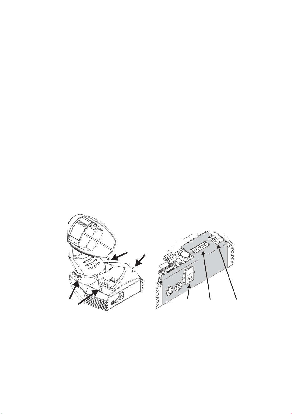
To change the voltage setting
1 Disconnect the fixture from power.
2 Remove the 4 base cover bolts with a 4 mm Allen wrench. Move the cover out of the
way of the switches without disconnecting wires.
3 Set the 5-position switch (A) to the setting closest to the AC voltage. Use the higher
setting if the voltage is halfway between 2 settings. For example, use the 230 V
setting instead of the 210 V setting for operation with 220 V power.
4 Set the 2-position switch (B) to the AC frequency (50 / 60 Hz).
5 Replace the cover and apply a new power setting label to the serial number label.
A
B
C
8
AC power
To install the main fuse
Fuses are provided for 100 - 130 V and 200 - 250 V operation. Use only the fuse
specified for the operating voltage.
1 Locate the bag containing the fuse for your AC voltage. Insert the fuse in the fuse
holder. The holder may be packed with the other fuse.
2 Remove the label covering the mains input socket.
3 Insert the fuse holder in the empty slot in the mains input socket (C).
To install a plug on the power cable
The power cable must be fitted with a grounding-type cord cap that fits your power
distribution system. Consult an electrician if you have any doubts about proper
installation.
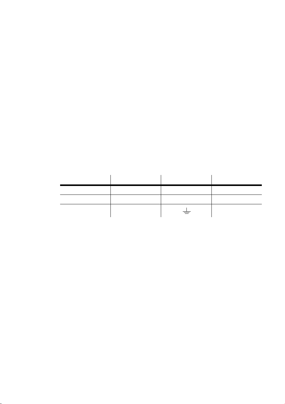
• Following the cord cap manufacturer’s instructions, connect the yellow and green wire
to ground (earth), the brown wire to live, and the blue wire to neutral. The table below
shows some pin identification schemes.
To apply power
Warning! The power cables must be undamaged and rated for the
electrical requirements of all connected devices.
Important! Powering through a dimmer system can damage the fixture.
• Connect the prepared cable to the mains input socket and the AC mains distribution
system. Do not connect the fixture to a dimmer system.
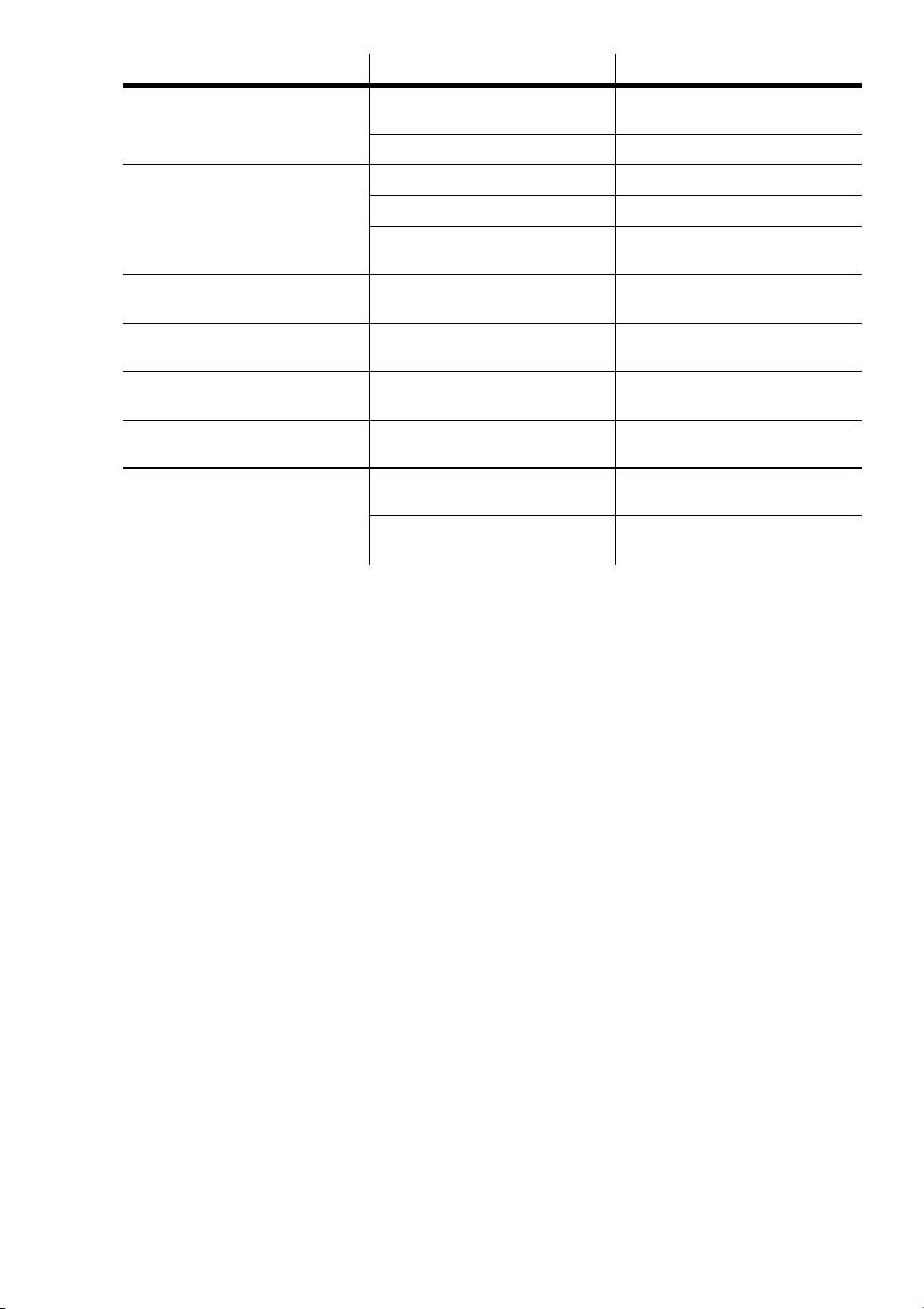
Wire Pin Marking Screw color
brown live “L” yellow or brass
blue neutral “N” silver
yellow/green ground green
Table 1: Cord cap connections
Installation
9
I
NSTALLATION
3
LOCATION AND ORIENTATION
For safe operation, install the MiniMAC Maestro in a location where
• it is at least 0.3 meters (12 inches) away from illuminated surfaces and combustible
materials.
• it is not easily touched or bumped.
• it is protected from rain and moisture.
• there is at least 0.1 meters (4 inches) clearance around the fans and air vents.
• there are no flammable materials nearby.
The MiniMAC Maestro may be installed in any orientation.
The intense light can burn or melt parts within a distance of 0.3 meters (12 inches).
The MiniMAC Maestro is programmed to close its shutter if it illuminates its own
base for more than 10 seconds. When installing fixtures side-by-side, avoid
illuminating one fixture with another.
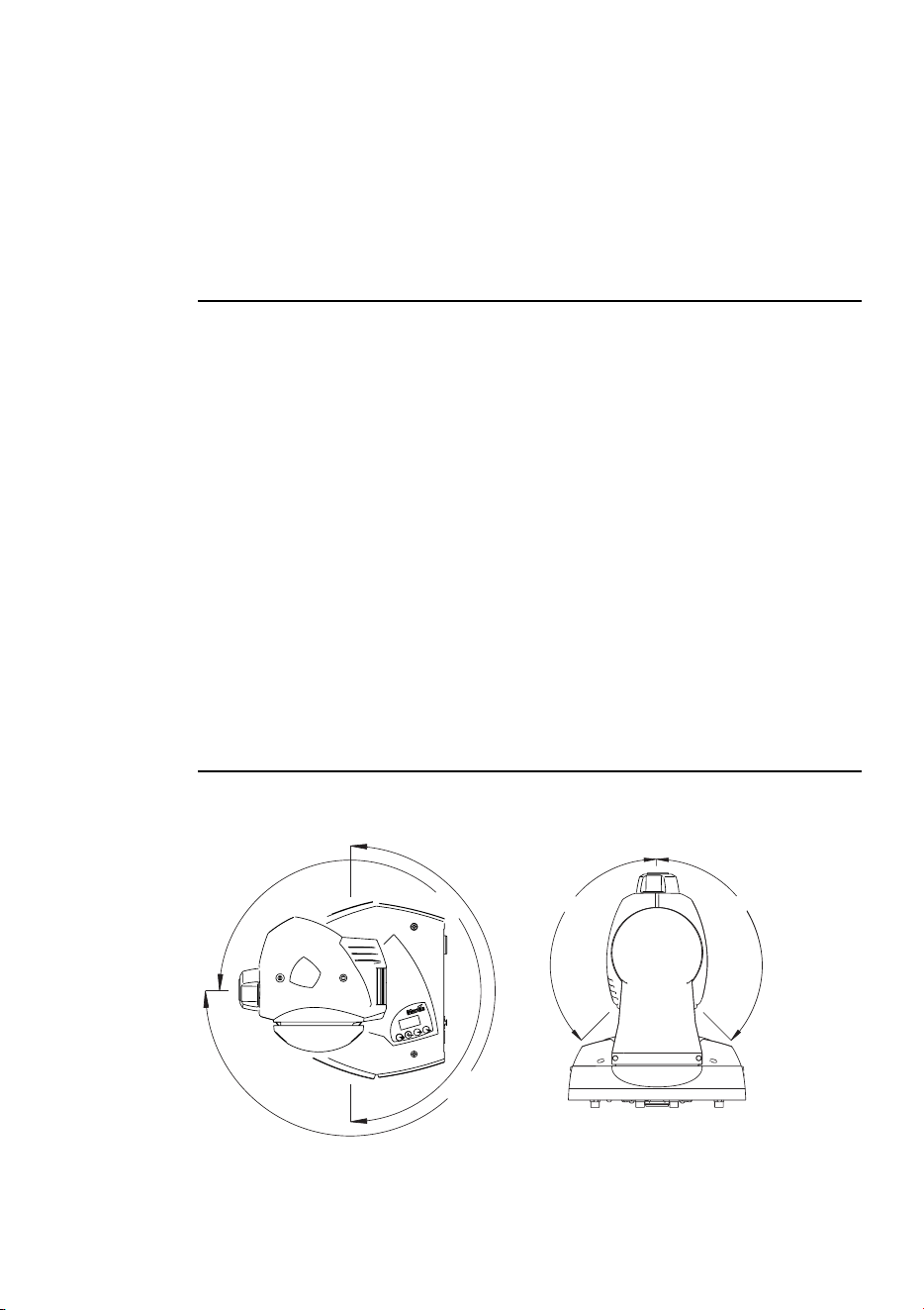
KEY DIMENSIONS
Head movement angles
270°
270°
135°
135°
10
Installation
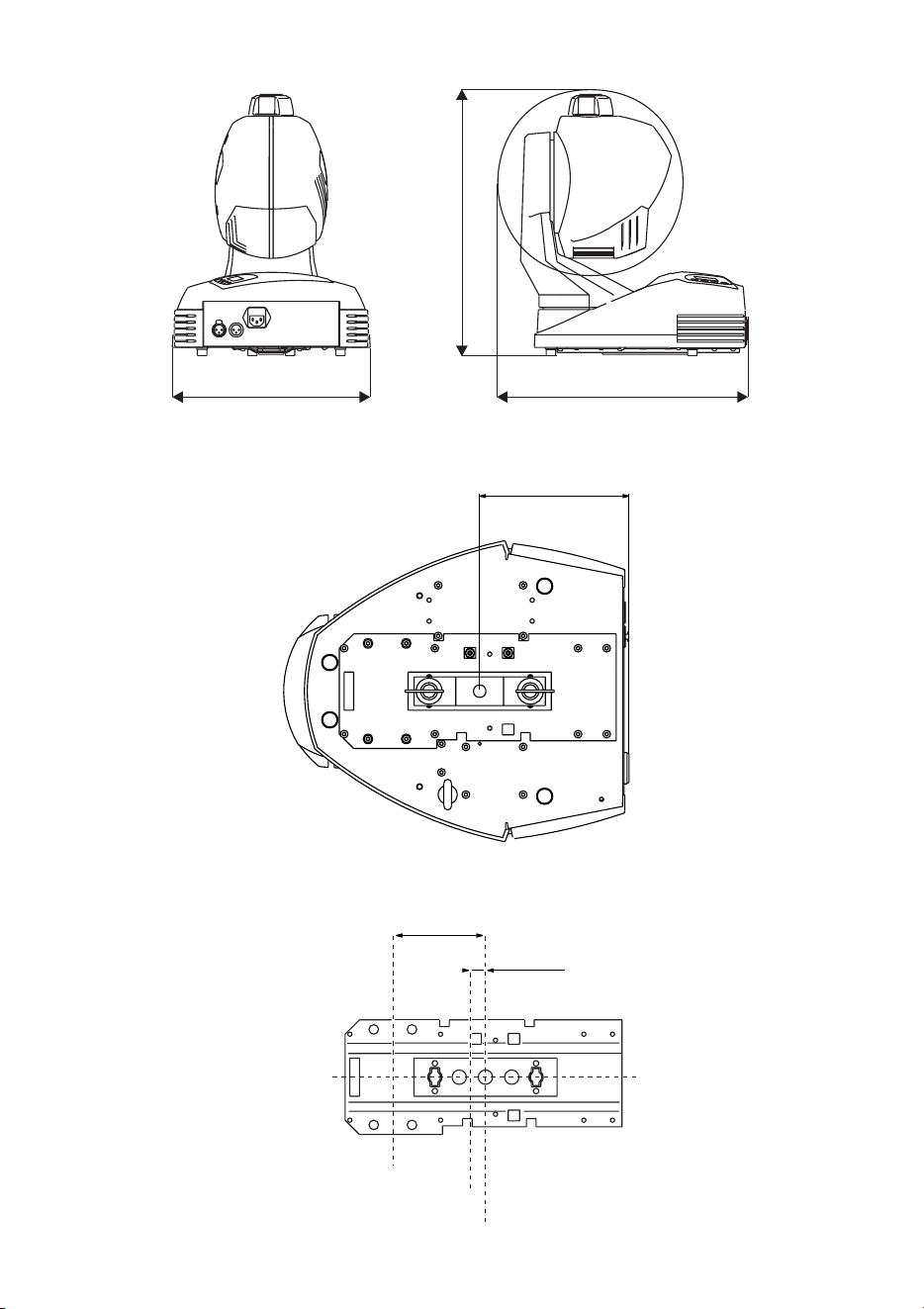
Exterior
Base
Attachment point relationship to center of movement
390 mm
415 mm
316 mm
156mm (6.1")
Center of attachment
Center of attachment
Center of attachment
Center of base
Center of base
Center of pan rotation
Center of pan rotation
16mm (0.6”)
16mm (0.6”)
97mm (3.8”)
97mm (3.8”)
Installation
11
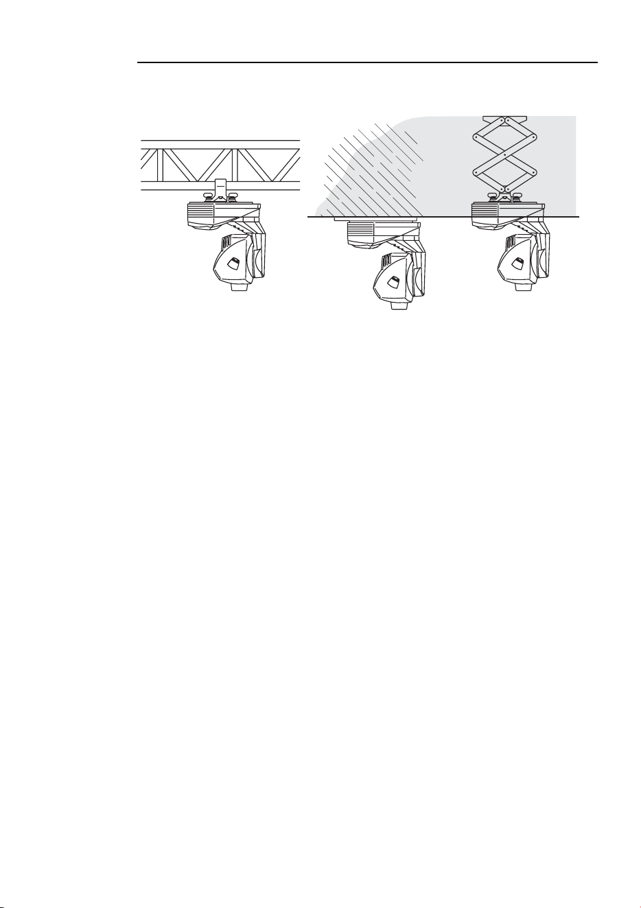
INSTALLATION OPTIONS
The MiniMAC Maestro can be rigged using a clamp, a flush mount bracket, or a
pantograph.
Clamp
The MiniMAC Maestro includes a bracket for attaching a rigging clamp with 12
mm (1/2 in.) hardware. Clamps available from Martin are listed on page 51.
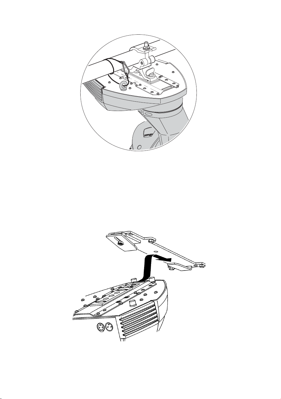
TO RIG THE FIXTURE
WARNING! Screw the included eye bolt securely into the base and fasten a
safety cable to the eye bolt.
1 Verify that the clamp is undamaged and can bear at least 10 times the weight of the
fixture. Verify that the structure can bear at least 10 times the weight of all installed
fixtures, clamps, cables, auxiliary equipment, etc.
2 Bolt a clamp to the included bracket with a grade 8.8 (minimum) M12 bolt and lock
nut, or as recommended by the clamp manufacturer, through the 13 mm hole in the
bracket.
3 Align the bracket with the keyholes in the base. Insert both locking pins into the holes
and turn both levers a full 1/4 turn clockwise to lock. The fasteners are locked only
when turned fully clockwise.
4 Screw the eye bolt securely into the base where shown below.
5 Block access below the work area.
6 Working from a stable platform, clamp the fixture to the structure.
12
Installation
7 Fasten a safety cable that can bear at least 10 times the weight of the fixture to the
structure and the eye bolt.
Flush mount bracket
Where no trussing system is available, you can use a special flush mount bracket
that is available for the MiniMAC series. It is a simple metal bracket, which enables
the MiniMAC to be flush mounted on a standard ceiling or wall. It provides a very
discrete installation, with a very limited air gap between the product and the ceiling
or wall. The bracket is designed so that one person can easily make the installation
alone.
The flush mount bracket can be ordered separately from a Martin dealer (P/N
91606009).
Installation
13
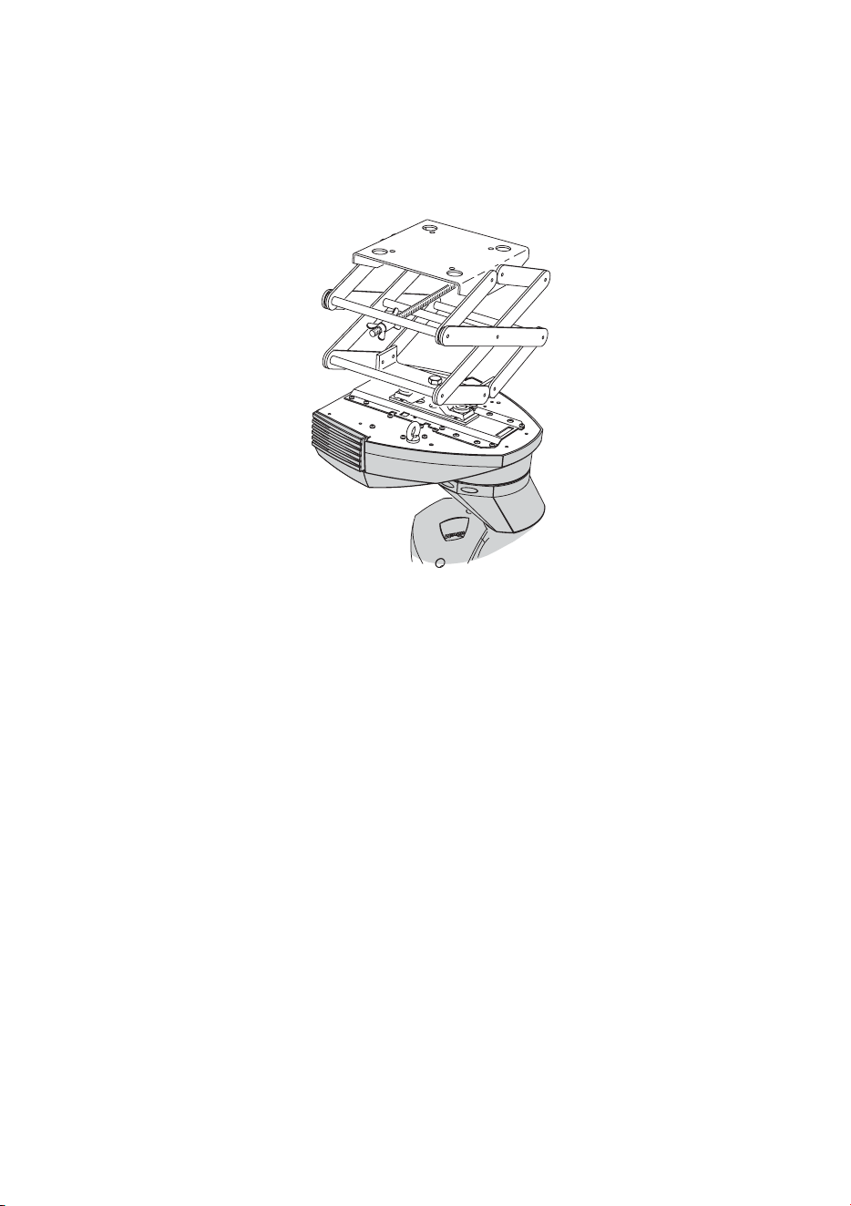
Pantograph
Another option for mounting the MiniMAC Maestro is the Martin Pantograph that
specifically designed for hanging Martin luminaries from ceilings or other load-
bearing structural elements. It may be used to suspend a fixture weighing up to 22
kg (48 lbs), and provides a drop from the ceiling to the attachment point of 12 to 62
cm (4.75 - 24.4 in.).
The pantograph can be ordered separately from a Martin dealer (P/N 91602006).
Ceiling template
If you are mounting the MiniMAC Maestro through a ceiling then a template that
can be used to cut out the shape of the fixture is available from the MiniMAC
Maestro support page on the Martin support site
(http://www.martin.dk/service/service.asp).
14
Control panel
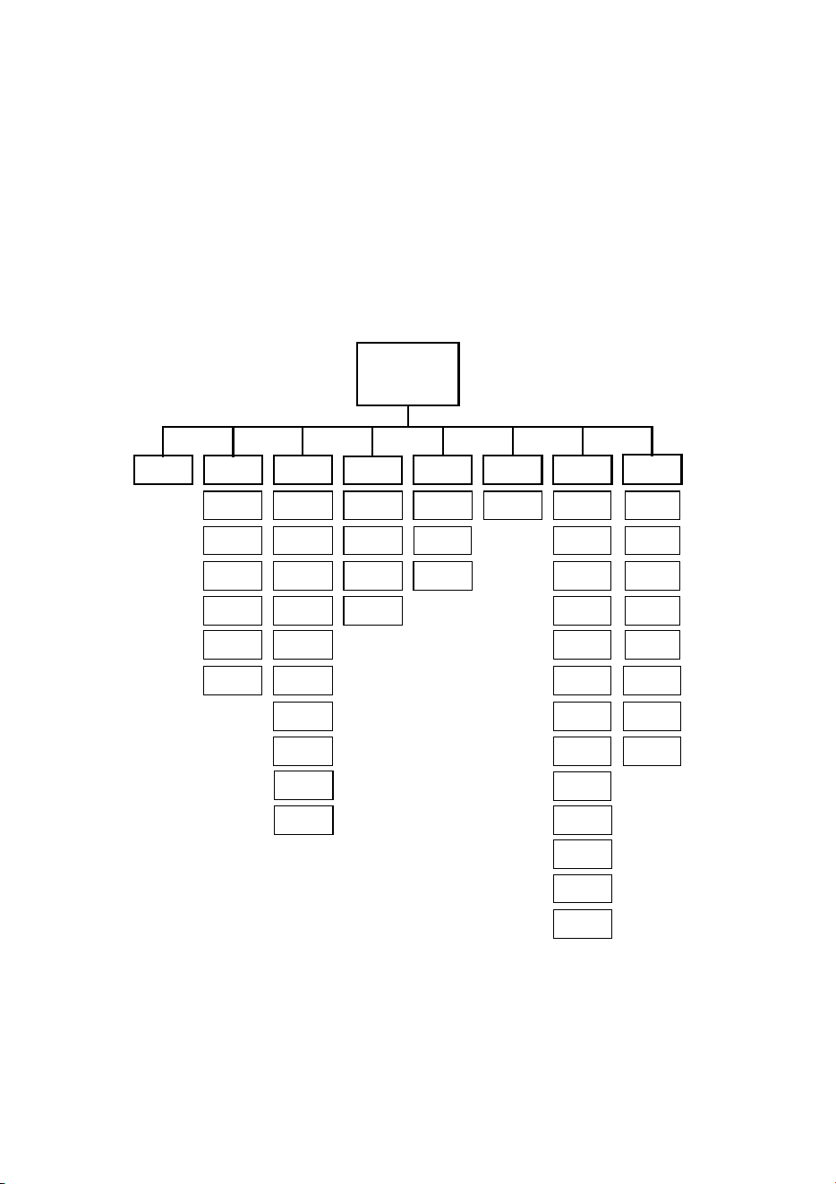
C
ONTROL
PANEL
4
The control panel is used to set user options; display lamp hours, DMX values, and
other information; perform tests, and operate the fixture in stand-alone mode. This
section describes the general options available from the control panel. Additional
options are described in later sections.
rgo
Pro
AdJ
Adr CtrtStPEr
Address/
Info
rst
LOn
LOF
FOC
rSt
LOn
SHU
FOC
tIL
LOF
ALO
rES
dIS
UPL
PCb
UTl
tSE
PtS
LOF
SHU
gob
PAn
InF
gob
rgo
P-t
FAC
run
P-t
Uer
LHr
LSt
Hr
LOg
rCS
d4
rCr
d2
d3
d1
uua
FAd
SCE
gbO
SrS
Err
Valid from software version 3.3

Control panel
15
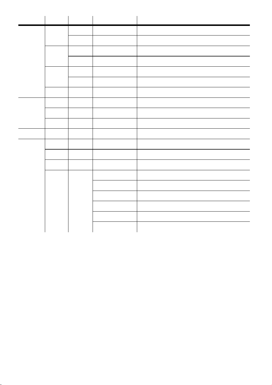
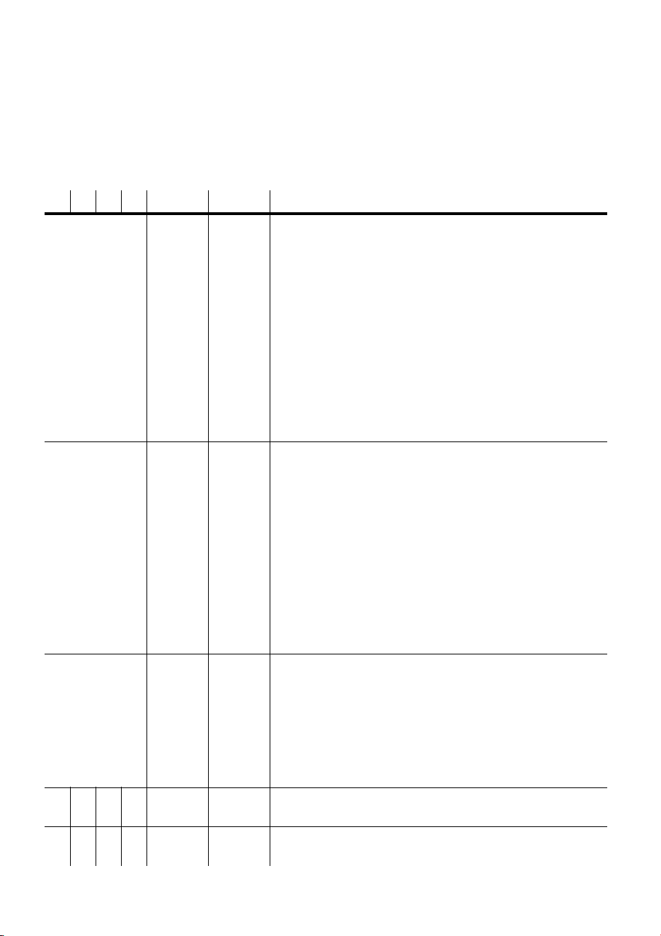
Level 1 Level 2 Level 3 Options Effect (default settings bold)
Adr - - 1-512
Set fixture address
Pro - -
d1
Set DMX mode 1 (8-bit, tracking)
d2
Set DMX mode 2 (16-bit, tracking)
d3
Set DMX mode 3 (8-bit, tracking/vector)
d4
Set DMX mode 4 (16-bit, tracking/vector)
rCS
Set remote control “send” mode
rCr
Set remote control “receive” mode
PEr
P-t
P t
On
Map pan to tilt channel and vice versa.
OFF
Select normal pan and tilt control.
PIn
ON
Reverse pan control (right Æ left).
OFF
Select normal pan (left Æ right).
tIn
ON
Reverse tilt control (down Æ up).
OFF
Select normal tilt (up Æ down).
PtS -
FSt
Optimize movement for speed.
SLO Optimize movement for smoothness.
LOF -
ON
Enable lamp-off without confirmation.
OFF
Require confirmation of lamp-off.
rES -
ON
Enable reset without confirmation.
OFF Require confirmation of reset command
ALO -
ON
Strike lamp automatically within 90 seconds.
OFF
Strike lamp from controller.
dIS -
ON
Keep display lit.
OFF
Turn display off 2 minutes after key press.
FAC - SUr
Restore default personality settings.
gbO -
ON
Blackout light while gobo changes.
OFF
Disable gobo blackout feature.
SrS
ON
Enable the store remote status feature.
OFF
Disable the store remote status feature.
Err
ON
Error messages are always displayed.
OFF
Error messages are not displayed.
Table 2: Control menu
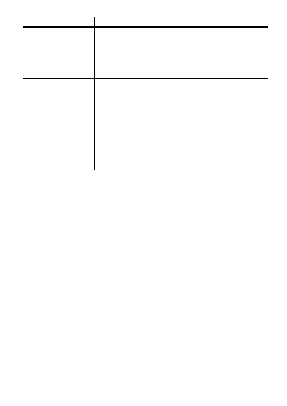
16
Control panel
InF
Hr
tot 0-9999
Read power-on hours since fabrication.
rES 0-9999
Read power-on hours since counter was reset.
LHr
tot 0-9999
Read lamp hours since fabrication.
rES 0-9999
Read lamp hours since counter was reset.
LSt
tot 0-9999
Read lamp strikes since fabrication.
rES 0-9999
Read lamp strikes since counter was reset.
UEr - 1.0-99.9
Read firmware version number.
tSt
tSE - run
Execute a general test of all effects.
Log - -
Not used.
PCb - SUr
Execute circuit board test. For service use only.
UtI UPL - SUr
Manually engage upload mode. See page 43.
Ctr
rst - -
Reset effects to home position.
LOn - -
Turn on lamp.
LOF - -
Turn off lamp.
SHU -
Opn
Open shutter.
CLO
Close shutter.
FSt
Set fast strobe.
nor
Set medium strobe.
SLO
Set slow strobe.
rnd
Set random strobe.
Level 1 Level 2 Level 3 Options Effect (default settings bold)
Table 2: Control menu

Control panel
17
Ctr
FOC - 0-255
Set focus (far to near).
gob
ind g1-g4
Select gobo and indexed rotation.
rot g1-g4
Select gobo and continuous rotation.
rgo
Fin 0-255
Set fine gobo index. Ind must be selected
under gob.
CrS 0-255
Set coarse gobo index.Ind must be selected
under
gob.
- 0-255
Set gobo rotation speed and direction. rot
must be selected under
gob.
PAn
Fin 0-255
Set fine pan position.
CrS 0-255
Set coarse pan position.
tIL
Fin 0-255
Set fine tilt position.
CrS 0-255
Set coarse tilt position.
uuA - 0-600
Set wait time in seconds.
FAd - 0-120
Set transition time in seconds.
SCE -
Sto
Save changes to current scene.
Add
Save new scene to end of sequence.
InS
Save new scene before current scene.
dEL
Delete the current scene.
nE
Call the next scene.
PrE
Call the previous scene.
CLr
Delete all scenes.
run -
OFF
Disable stand-alone operation.
Sin
Set stand-alone operation on a single fixture.
Snd
Set fixture to be the master in multiple fixture
stand-alone mode. Only one fixture on a link
may be the master.
SYn
Set fixture to synchronize with master in multiple
fixture stand-alone mode. (Executes own
scenes.)
Level 1 Level 2 Level 3 Options Effect (default settings bold)
Table 2: Control menu
18
Control panel
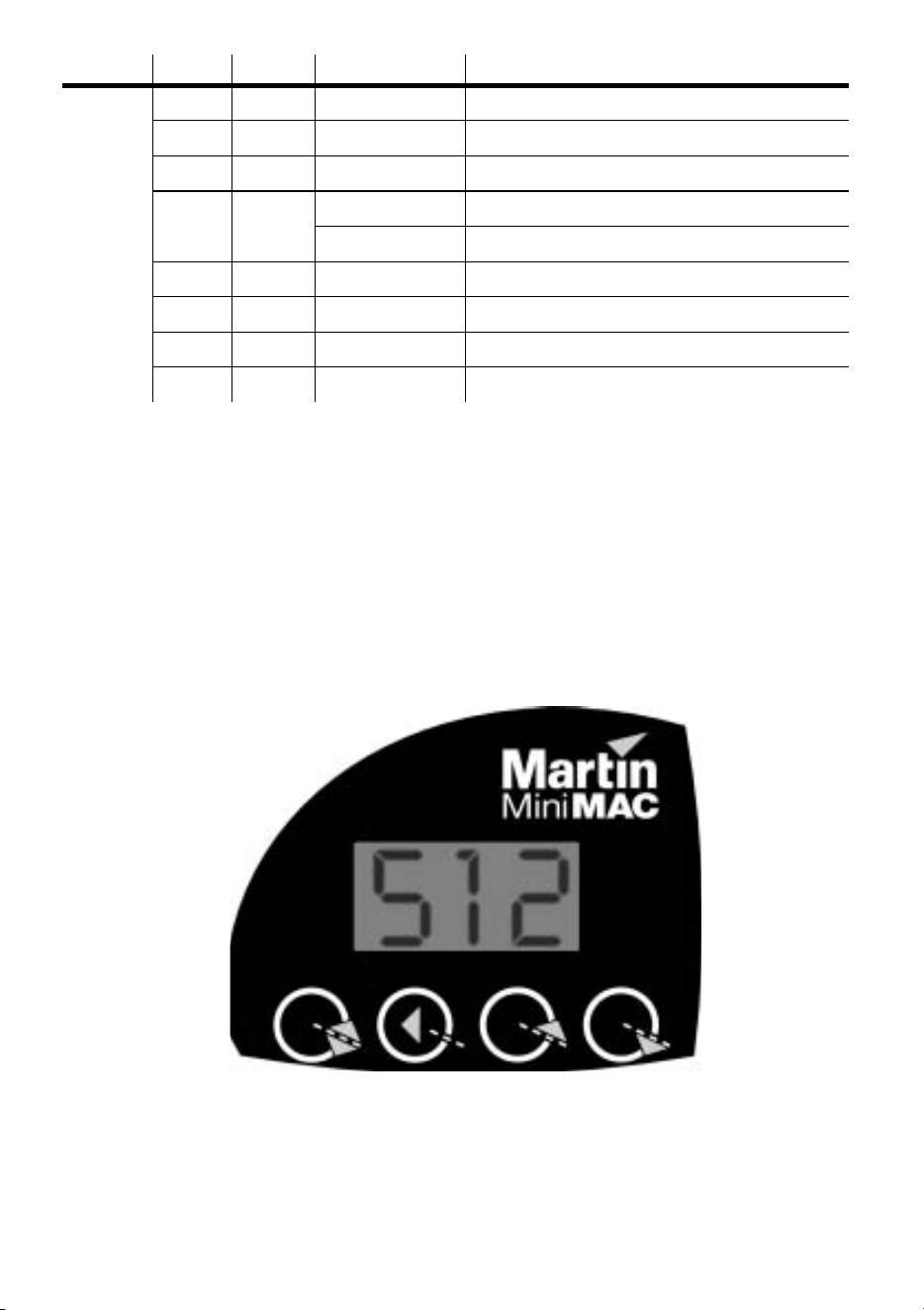
To navigate the control menu
• In DMX mode, the control panel displays the fixture address at the top of the menu. In
Stand-alone mode, the current scene number is displayed after the letter P. If there
are any error messages (page 46) these are displayed as well. To get to the top of the
menu, press [menu] repeatedly. From the top, press [menu] to enter the main menu.
Press [up] or [down] to scroll through menus and press [enter] to view submenus. To
activate a setting or function, press [enter]. To return to the previous menu or to
escape without making a selection, press [menu].
To invert the display
• Press [up] and [down] at the same time.
Adj
rst - -
Reset effects to home position.
LOn - -
Turn on lamp.
LOF - -
Turn off lamp.
SHU -
OPn
Open shutter.
CLO
Close shutter.
FOC - FAr/nEA
Move focus lens to limits.
gob - g1/g4
Select gobo.
rgo - g1-g4
Select gobo and rotation.
P-t - P1-P7
Move head to neutral and extreme positions.
Level 1 Level 2 Level 3 Options Effect (default settings bold)
Table 2: Control menu
[menu] [enter] [up] [down]

Control panel
19
PERSONALITIES
The following settings are available to modify fixture behavior.
Pan/tilt swap: Map pan to the tilt channel and tilt to the pan channel to provide
more intuitive control of fixtures mounted sideways.
Inverse pan: Flip pan movement to right-to-left instead of left-to-right.
Inverse tilt: Flip tilt movement to down-to-up instead of up-to-down.
Pan/tilt speed: Optimize motor control for speed or smoothness.
DMX lamp-off: Disable the lamp-off command unless image 4 is selected and
focus is set to closest (100 percent).
DMX reset: Disable the reset command unless image 4 is selected and focus is set
to closest (100 percent).
Automatic lamp-on: Strike lamps automatically within 90 seconds of applying
power to the fixture. Timing is staggered to prevent excessive current draw.
Display: Turn off the display 2 minutes after the last key press or leave it on. This
setting will be overridden by error messages.
Gobo blackout: Blackout the light automatically - by closing shutter - to make
gobo changes invisible.
Store remote status: When active, this option links the Run/Stop action on the IR
remote to the execution settings for stand-alone operation. When you select run or
stop via the remote control this will update the fixture’s execution settings. This
enables you to – via the IR remote - switch on or off the automatic starting of stand-
alone operation when the fixture is powered on.
Errors message toggle:This enables error messages to be switched on or off. This
enables, for example, the continued programming of a fixture that has a non-critical
error. The default setting is On, which means that errors messages will always be
displayed.
To select a personality setting
•Scroll to PEr in the main menu, press [enter], scroll to the desired personality, and
press [enter]. Select the desired option and press [enter]. Refer to Table 2.
To restore default personality settings
•Scroll to PEr in the main menu, press [enter], and scroll to FAC. Press [enter]
twice to confirm and execute the command.

20
Control panel
READOUTS
The MiniMAC Maestro provides readouts to track usage, maintenance intervals,
lamp life, and software version. Values from 1000 to 9999 are automatically
scrolled and counters roll over to 0 when they reach 10,000.
To display or reset a readout
1Scroll to Inf in the main menu, press [enter] and scroll to the desired readout.
Press [enter] and scroll to the desired option. Press [enter] to display the information.
2 (Optional) To reset a counter, press [up] until the readout displays
0.
TEST PROGRAMS
Test sequence: The test sequence allows you to check all effects quickly. At the end
of the test cycle, effects return to their home position briefly before the test repeats.
To run the test, navigate to
tSt / tSE / run and press [enter]. To stop the test,
press [menu].
PCb: For service use only. Executing this test with motors connected may cause
damage to the circuit board.
To test DMX control values
1 On the controller, program a set of commands for the fixture.
2Scroll to
tSt in the main menu, press [enter] and scroll to LOg. Press [enter].
3 Press [enter] to display the start code. The start code must be 0. Press [menu].
4 Scroll through the effects and press [enter] to display the DMX values received.
Compare the values with the DMX protocol.
UPLOAD MODE
Software upload mode is normally engaged automatically. Use this option only if
automatic upload fails. See “Installing software” on page 43.
MANUAL CONTROL
The manual control menu (Ctr) provides limited manual operation and is used to
program and execute scenes as in Stand-alone mode.

Control panel
21
ADJUSTMENT CONTROL
The adjustment menu (AdJ) provides manual control for service use.
22
Controller operation
C
ONTROLLER
OPERATION
5
This section describes setup and operation with DMX controllers.
Important! Controller operation is disabled if stand-alone mode is enabled.
DATA CONNECTION
RECOMMENDED CABLE
Reliable data communication begins with the right cable. Most microphone cable
does not transmit digital data reliably over long runs. For best results, use shielded,
twisted-pair cable designed for RS-485 applications with low capacitance and a
characteristic impedance of 85 to 150 ohms. The minimum wire size is 0.2 mm (24
AWG) for runs up to 300 meters (1000 ft.) and 0.322 mm (26 AWG) for runs up
500 meters (1640 ft.).
Your Martin dealer can supply the right cable in various lengths.
CONNECTIONS
The XLR data sockets are wired pin 1 to ground, pin 2 to signal - (cold), and pin 3
to signal + (hot). This is the standard pin assignment for DMX devices.
One or more adaptor cables may be required to connect the MiniMAC Maestro to
the controller and other lights if they have 5-pin connectors or reversed signal
polarity on pins 2 and 3.
Phase-Reversing
Adaptor
Male Female
1
2
3
1
2
3
3-pin to 3-pin
P/N 11820006
Adaptor
Male Female
1
2
3
4
5
1
2
3
5-pin to 3-pin
P/N 11820005
Adaptor
Male Female
1
2
3
1
2
3
4
5
3-pin to 5-pin
P/N 11820004
Controller operation
23
To connect for controller operation
1 Connect a data cable to the controller’s data output. If controller has a 5-pin output,
use a 5-pin male to 3-pin female adaptor cable (P/N 11820005). Lead the cable from
the controller to the first fixture and plug it into the data input.
2 Connect the output of the fixture closest to the controller
to the input of the next fixture. If connecting to a fixture
with reversed-polarity (pin 3 cold), insert a phase-
reversing cable between the two fixtures.
3 Continue connecting fixtures output to input. Up to 32
devices may be connected on a serial link.
4 Terminate the link by inserting a male termination plug
(P/N 91613017) into the data output of the last fixture. A
termination plug is simply an XLR connector with a 120
ohm, 0.25 W resistor soldered across pins 2 and 3.
MODE SELECTION
The MiniMAC Maestro has 4 control modes for operation with DMX512
controllers. The modes mix tracking and vector control with 8 and 16-bit gobo, pan,
and tilt position control in different combinations. Mode 1 provides basic control
and requires the fewest channels. Mode 4 provides the full set of control options.
TRACKING VERSUS VECTOR CONTROL
With tracking control (all modes) the speed at which an effect changes from one
position to another (fades) is determined by programming a fade time between 2
scenes using a cross-fader.
With vector control (modes 3 and 4), speed is programmed on separate speed
channels. This provides a way to program fades on controllers without cross-faders.
With some controllers, vector control provides smoother movement than tracking
control, particularly at slow speeds.
Mode Control Resolution Channels
D1 Tracking 8-bit 6
D2 Tracking 16-bit 9
D3 Tracking/Vector 8-bit 8
D4 Tracking/Vector 16-bit 11
Table 3: DMX mode summary
Male XLR
1
2
3
Male
P/N 91613017
120
Termination Plug

24
Controller operation
The speed channel must be set to “tracking speed” when using a cross-fader
(tracking control) to program fades.
The speed channels also provide a “blackout speed” that makes transitions invisible.
8-BIT VERSUS 16-BIT PAN/TILT RESOLUTION
The 8-bit modes (1 and 3) provides coarser control of pan, tilt, and gobo indexing
than the 16-bit modes (2 and 4), which use 3 additional control channels for fine
position control.
To select DMX mode
1Scroll to Pro in the main menu, press [enter], and scroll to the desired DMX mode,
d1, d2, d3, or d4.
2 Press [enter] to activate the setting and return to the main menu.
ADDRESS SELECTION
The control address, also known as the start channel, is the first channel used to
receive instructions from the controller. The total number of channels used depends
on the control mode.
Be sure to allow adequate channels when setting the control address. If control
channels for one fixture overlap control channels for another fixture, then one of the
fixtures will receive the wrong commands. Two MiniMAC Maestros operating in
the same control mode may share the same address if they are to respond
identically. They will receive the same commands and individual control will be
impossible.
To set the control address
1Scroll to Adr in the main menu and press [enter]. The current address is displayed.
2 Scroll to the address that is assigned to the fixture on the controller. Press [enter] to
activate the address setting.
CONTROLLABLE EFFECTS
LAMP POWER
Lamp power can be switched on and off from the controller. When set-up for
controller operation, and with the automatic lamp-on personality set to off, the
lamp remains off until a lamp-on command is sent.

Controller operation
25
Note: A peak of electric current many times the operating current is drawn briefly
when striking a lamp. Striking many discharge lamps at once may cause a voltage
drop that prevents lamps from striking or trips circuit breakers. When striking
multiple fixtures, space lamp-on commands at 5 second intervals.
The lamp must be allowed to cool for several minutes after turning it off before it
can be turned back on. To prevent accidental lamp-off commands, this command
can be partially disabled from the control panel: see page 19. If a hot lamp does not
strike, send the lamp off command and wait several minutes before trying again.
RESET
All effects can be reset to their index positions from the controller. To prevent
accidental resets, the command can be partially disabled from the control panel: see
page 19.
SHUTTER
The mechanical shutter opens, closes, and strobes at variable and random rates. The
shutter closes automatically after 10 seconds if the light beam is projected on the
base to prevent heat damage. The shutter opens instantly when the beam is moved.
FOCUS
The focus lens allows focussing from approximately 1 meter to infinity.
GOBOS
The MiniMAC Maestro provides 4 rotating gobo positions. Each position can be
indexed with 8-bit or 16-bit resolution or continuously rotated at variable speeds.
PAN AND TILT
The head pans 540° and tilts 270°. If knocked or jarred out of position, the pan
position automatically resets if the arm reaches the right limit and the tilt position
automatically resets if the arm reaches the bottom limit. In some cases, the limit can
be reached by setting the pan or tilt value to 255. Otherwise, the fixture can be reset
as described above.

26
Stand-alone operation
S
TAND
-
ALONE
OPERATION
6
In stand-alone mode, individual MiniMAC Maestros can be programmed with up to
20 scenes without an external controller. Multiple MiniMAC Maestros can be
linked together and scenes on all fixtures can be synchronously triggered by a
“master” fixture.
CONTROL MODES
The MiniMAC Maestro provides two stand-alone modes that allow you to program
and execute a sequence of up to 20 scenes without an external controller. The major
differences between the two modes are show in Table 4.
In DMX Stand-Alone Mode, up to 32 MiniMAC Maestros may be connected for
synchronized operation triggered by a “master” fixture. Execution may be set to
start automatically upon startup, selected from the control panel, or toggled on/off
with an MC-X controller, which also provides direct selection of 7 scenes.
Programming is done from each fixture’s control panel. Fixtures may be
programmed in IR Mode and then operated in DMX Stand-Alone Mode if stand-
alone operation of more than 10 fixtures is required.
The Infrared Remote Control (IR) Mode supports up to 10 fixtures and requires
the infrared transmitter and receiver listed on page 51. (One receiver supports up to
10 fixtures.) Programming and execution is done from the handheld remote control
or the fixture control panels.
When working with multiple fixtures in either mode, each fixture is individually
programmed with its own scenes, and then during playback, scenes of the same
DMX Stand-Alone Mode IR Remote Control Mode
Maximum fixtures 32 10
Protocol setting d4 rCS (master), rCr (others)
Link termination yes no
Execution
automatic, control panel,
and MC-X
IR remote, control panel
Table 4: Stand-alone mode comparison

Stand-alone operation
27
number on each fixture can all be triggered to start simultaneously by a master
fixture. This is further explained in the section “About scene timing” on page 29.
FIXTURE SETUP
Important: The IR mode address is different from the DMX mode address
and can only be set after rCS or rCr has been selected.
To setup multiple fixtures for DMX Stand-Alone operation
1 Plug a data cable into the OUT socket of the first fixture and the IN socket of the next
fixture. Repeat as required to connect up to 32 fixtures.
2 Insert a male termination plug (P/N 91613017) into the OUT socket of the last fixture.
If you experience random “flicker” or other unexplained control problems, insert a
female termination plug (P/N 91613018) into the IN socket of the first fixture.
3 Set all fixtures to DMX mode 4. From the control panel, scroll to
Pro in the main
menu, press [enter]. Select
d4. Press [enter] to activate the setting. Address setting
is not required.
4 Using the run options under the control menu set the execution settings of the
respective fixtures to run as slaves, or as the master (only one fixture on the link may
be the master). See “Execution commands” on page 32.
5 (Optional) Set the personality options described on page 19.
6 Study “About scene timing” on page 29, ensuring that you understand it and then use
the menus to program scenes into each fixture. See “Menu commands” on page 30.
To setup one fixture for IR Stand-Alone operation
1 Insert the receiver module into the serial data In socket. Position the sensor arm as
desired but avoid turning it more than necessary.
2Scroll to
Pro in the control panel main menu, press [enter], and scroll to rCS.
Press [enter].
3 Select
Adr from the main menu and press [enter]. Select an address from 0 to 9
and press [enter].
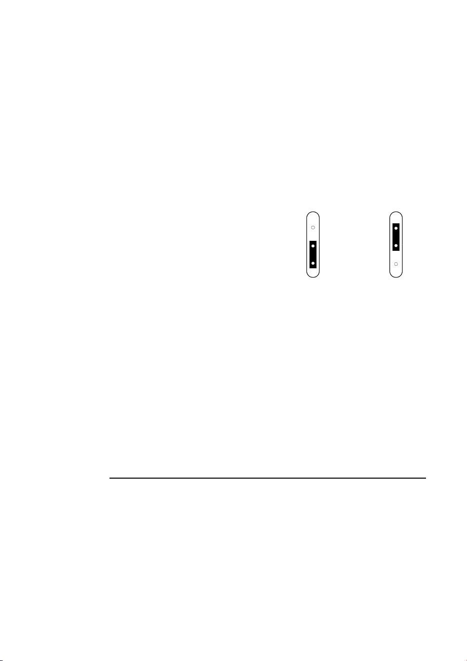
4 Stand 2 meters (6 ft.) away from the fixture, point the remote control at the receiver,
and press the lamp power button. If there is no response, try the ID button. If there is
still no response, reverse the sensor head by rotating the sensor arm 180° and folding
it over.
5 (Optional) Set the gobo blackout, display, and automatic lamp-on personality options
as described on page 19.

28
Stand-alone operation
6 Study “About scene timing” on page 29, ensuring that you understand it and then use
the remote control to program scenes into the fixture. See “Remote control
commands” on page 32.
To setup multiple fixtures for IR Stand-Alone operation
Important! Do not terminate the link in IR Mode.
Note Some early versions of the MiniMAC Maestro receiver module
have the restriction that they only support IR operation for a
single fixture. These modules can be easily identified as they
are black. The newer version that supports multiple fixtures is
grey.
1 Select a fixture to be the master. For convenience, select an end fixture close to a
good programming spot. Insert the receiver module into the master’s serial data In
socket. Position the sensor arm as desired but avoid turning it more than necessary.
2 From the control panel of the master fixture, scroll to
Pro in the main menu, press
[enter], and scroll to
rCS (remote control, send). Press [enter] to activate the
setting. Select
Adr from the main menu and press [enter]. Select an address from 0
to 9 and press [enter].
3 Stand 2 meters (6 ft.) away from the fixture, point the remote control at the receiver,
and press the lamp power button. If there is no response, try the ID button. If there is
still no response, reverse the sensor head by rotating the sensor arm 180° and folding
it over.
4 Plug a data cable into the OUT socket of the master fixture and the IN socket of the
next fixture. Repeat as required to connect up to 10 fixtures. DO NOT place a
termination plug in the output of the last fixture.
5 On each fixture except the master, scroll to
Pro in the main menu, press [enter],
and scroll to
rCr (remote control, receive). Press [enter] to activate the setting.
Select
Adr from the main menu and press [enter]. Select an unused address from 0
to 9 and press [enter]. (Each fixture must have a unique address: they may share an
address, though, if you always want them to behave identically.)
6 (Optional) Set the gobo blackout, display, and automatic lamp-on personality options
as described on page 19.
7 Study “About scene timing” on page 29, ensuring that you understand it and then use
the remote control to program scenes into each fixture. See “Remote control
commands” on page 32.
Stand-alone operation
29
ABOUT SCENE TIMING
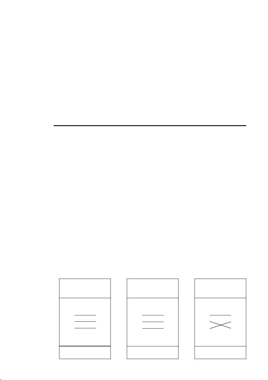
Each scene has a dynamic part -
the fade - during which effects
move to the scene’s programmed
positions, and a static part - the
wait - where effects do not
change.
The duration of the fade and wait
is programmed individually for
each scene. The fade time may be
0 - 120 seconds; the wait time
may be 0 - 600 seconds. The total
time it takes a scene to execute is
the sum of the fade and wait
times.
When operating multiple fixtures, the wait time is determined by a master fixture.
Each fixture fades and waits at the its own rate and then remains in the “wait state”
until receiving a start scene xx command from the master fixture.
When programming in Master/Slave situations, keep in mind the following:
• Every fixture can have up to 20 on-board scenes with individual fade & wait times.
• Scenes are numbered from 0 to 19.
• A scene contains a fade-section, followed by a wait-section.
• When running "synchronous triggering" the master issues commands to the slave
fixtures to "go to scene xx", where xx is the scene number that master will execute
next.
• If a slave has fewer scenes than the master directs it to run, it will derive which
scene to go to by dividing the number of the scene it has been commanded to go to
(scene 5, for example) by the total number of scenes that the slave fixture has (4, for
example) in whole numbers (no decimal places). In this example 5 divided by 4
results in 1, with 1 remainder. This remainder will be the number of the scene that
the slave fixture starts - scene 1. Generally though, when a Slave fixture reaches its
own last scene before the Master fixture, a "go to scene x" message will result in the
first scene being played.
• If a slave has more scenes than the master calls, the last scenes in the slave will
never be executed.
• A slave fixture will not listen for the next message from the master fixture before it
has finished its current scene. This may result in skipping a slave scene if slave has
a longer scene time than master. Note that in the following example that the Slave
Fade
Wait
Wait
Wait
Fade
Fade
S
c
e
n
e
1
S
c
e
n
e
2
S
c
e
n
e
3
S
c
e
n
e
1
S
c
e
n
e
2
S
c
e
n
e
3
30
Stand-alone operation
synchronizes its scenes with the Master, and also note that scene S4 that is
programmed in the Slave fixture will not run.
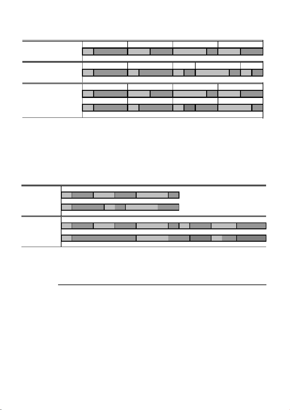
• The scene times in the Master fixture should be equal to or longer than the
corresponding scene times of the other fixtures. You may get undesirable results if,
for example, a scene is programmed in the master to last 10 seconds and in other
fixtures to fade for 15 seconds. Note that in the following example the scenes in the
Slave run out of their programmed sequence because scenes 0 and 2 on the Slave
are longer than the corresponding scenes on the Master.
MENU COMMANDS
The menu commands can be used to program and execute scenes in both DMX
Stand-Alone Mode and IR Remote Control Mode.
Note Control panel actions sometimes result in a information being
written to the fixture’s memory. If the fixture is powered off
during this process updates may be lost. A “Memory not yet
stored” warning indicator appear as a red dot in the left side of
the control panel display during memory update. Do not power
the fixture off while this is lit.
SCENE COMMANDS
Store scene (SCE/Sto): Save settings in the current scene.
F=fade, W=wait Timeline =>
M0 M1 M2 M3
Programmed in Master F W F W F W F W
S0 S1 S2 S3 S4
Programmed in Slave F W F W F W F W F W
Result M0 M1 M2 M3
FW FWF WFW
S0 S1 S2 S3
FW FW FW ----F W
M=master, S=slave
F=fade, W=wait Time >
Programmed M0 M1 M2
Master F W F W F W
S0 S1 S2
Slave F W F W F W
Result M0 M1 M2 M0 M1
Master F W F W F W F W F W
S0 S2 S1
Slave F W F W .. .. FW .. ..

Stand-alone operation
31
Add scene (SCE/Add): Save settings in a new scene at the end of the sequence.
Insert scene (SCE/InS): Save settings in a new scene before the current scene,
which moves up a number. Tip: Think of the Add and Insert commands as Save
commands, to be used as the last step after programming all effects.
Delete scene (
SCE/dEL): Remove the current scene from memory. Scenes
above the deleted scene move down a number.
Next scene (
SCE/nE): Step to the next scene.
Previous scene (SCE/PrE): Step to the previous scene.
Clear scenes (SCE/CLr): Remove all scenes from the fixture memory.
EFFECTS COMMANDS
Lamp on (LOn): Apply power to the lamp. In DMX Stand-Alone Mode, this
command must be programmed in at least one scene if the automatic lamp on
feature is disabled.
Lamp off (
LOF): Turn off the lamp. A hot lamp must cool for several minutes
before it will strike again.
Shutter control (
SHU): Open, close, and flash the shutter at different speeds. (See
Table 2.)
Focus adjustment (
FOC): Set focus position.
Indexed gobo selection (gob/ind): Select a gobo for projection at a fixed
angle.
Rotating gobo selection (
gob/rot): Select a gobo for projection with
continuous rotation.
Gobo index (
rgo/CrS, Fin): Set gobo angle. (Applies only when an
indexed gobo is selected.) Select
CrS first, set the rough angle, and then fine-tune
with
Fin. (See Table 2.)
Gobo rotation (rgo): Set speed and direction of continuous rotation. (Applies
only when a rotating gobo is selected.)
Pan position (
PAn/CrS,Fin): Set pan angle. Select CrS first, set the
rough angle, and then fine-tune if desired with
Fin.
Tilt position (tIL/CrS,Fin): Set tilt angle. Select CrS first, set the rough
angle, and then fine-tune if desired with
Fin.
TIMING COMMANDS
Scene wait time (UUA): Set the scene wait time in seconds.
Scene fade time (FAd): Set the scene fade time in seconds.

32
Stand-alone operation
EXECUTION COMMANDS
Important! The execution setting automatically resumes on startup.
Off (
run/OFF): Stop stand-alone execution.
Run single fixture (run/Sin): Start stand-alone operation of a single fixture.
Run master fixture (run/Snd): Select the master fixture and start stand-alone
operation.
Run synchronized fixture (
run/SYn): Select a non-master (synchronized)
fixture and start stand-alone operation.
MC-X EXECUTION
To execute stand-alone scenes with an MC-X Controller
1 Connect the MC-X controller to the MiniMAC Maestro’s data input. If multiple
MiniMAC Maestros are connected, plug the controller into the first fixture in the link.
2 On each fixture, select
Ctr / run / OFF and press [enter]. Press [menu] to exit
the
Ctr menu. Set each fixture to DMX mode 4.
3 To trigger scenes 00-06, press the numbered preset buttons on the MC-X.
4 To have each fixture run its own routine, press [Auto].
REMOTE CONTROL COMMANDS
Important! Fixtures blink to acknowledge commands from the remote
control.
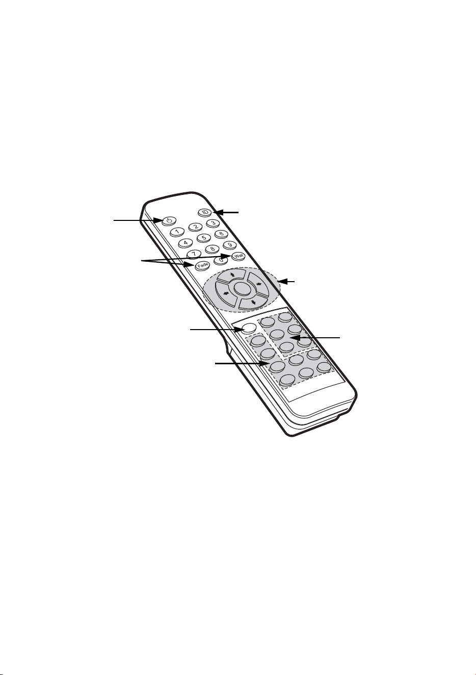
FIXTURE SELECTION
Each fixture must be assigned an address from 0 - 9 during setup so that it can be
individually controlled with the remote control. To select a fixture, press ID and
enter its address using the number keys. Multiple fixtures may be selected by
entering more than one address. For example, pressing [ID] [1] [2] [3] selects
fixtures 1, 2, and 3.
LAMP POWER
The lamp power button toggles lamp power on and off on selected fixtures. The
button must be held for 5 seconds to turn lamp power off. Note: Lamps cannot be
Stand-alone operation
33
turned off during scene execution and a discharge lamp must cool for several
minutes after being turned off before it can be turned back on.
SCENE TIMING
Fade and wait times are set by pressing the scene timing buttons and entering the
desired time in seconds using the number keys.
SCENE SELECTION
Scenes are created, selected, saved, and deleted using the six scene keys. The
current scene is displayed on the fixture display after the letter “
r” during editing
and after the letter “
P” during execution.
Fixture selection
Position adjustment
Scene selection
Effects selection
Execution
Scene timing
Lamp power

34
Stand-alone operation
• Prev (previous scene) scrolls backwards through scenes on
selected fixtures. The fixture blinks three times when the
first scene is reached.
• Next (next scene) scrolls forwards through scenes on
selected fixtures. The fixture blinks three times when the
last scene is reached.
• Store (store scene) saves effect and timing settings to the
current scene. Fixtures confirm the command by blinking
twice.
• Delete (delete scene) removes the current scene from
memory. Scenes above the deleted scene are renumbered.
Fixtures confirm the command by blinking twice.
• INS (insert scene) creates and saves a new scene before the
current scene, which moves up a number. Fixtures confirm
the command by blinking twice. If a fixture blinks three
times, its memory is full.
• ADD (add scene) creates a new scene at the end of the
sequence with the settings that are active when the scene is
created. Fixtures confirm the command by blinking twice. If
a fixture responds by blinking three times, its memory is full.
EFFECTS ADJUSTMENT
The look of a scene is programmed by first selecting an option with the effect
selection buttons and then adjusting the option with the position adjustment buttons.
When two effects - pan and tilt for example - are assigned to a selection button, the
up/down arrows control one effect and the left/right arrows control the other effect.
If there is only one effect, the up/down arrows usually provide course adjustment
and the left/right arrows usually provide fine adjustment. The middle button returns
effects to a default position.
Some effects do not apply. The fixture acknowledges valid effect selections by
blinking once.
EXECUTION
The Run/Stop button toggles scene execution on/off on selected fixtures. Scenes
execute in a continuous ascending loop.
All remote control functions except Run/Stop are disabled during execution.
The Store Remote Status personality option, which is active by default (see
“Control panel” on page 14), links the Run/Stop action on the IR remote to the
execution settings for stand-alone operation. This means that when you select run or
stop via the remote control this will update the fixture’s execution settings. This
enables you to – via the IR remote - switch on or off the automatic starting of stand-
alone operation when the fixture is powered on.
00 01 02
00 01 02 03
00 01 02 03
Store saves
settings in the
current scene.
Add saves settings
in a new scene at
the end of the
sequence.
Insert saves
settings in a new
scene before the
current scene.
Stand-alone operation
35
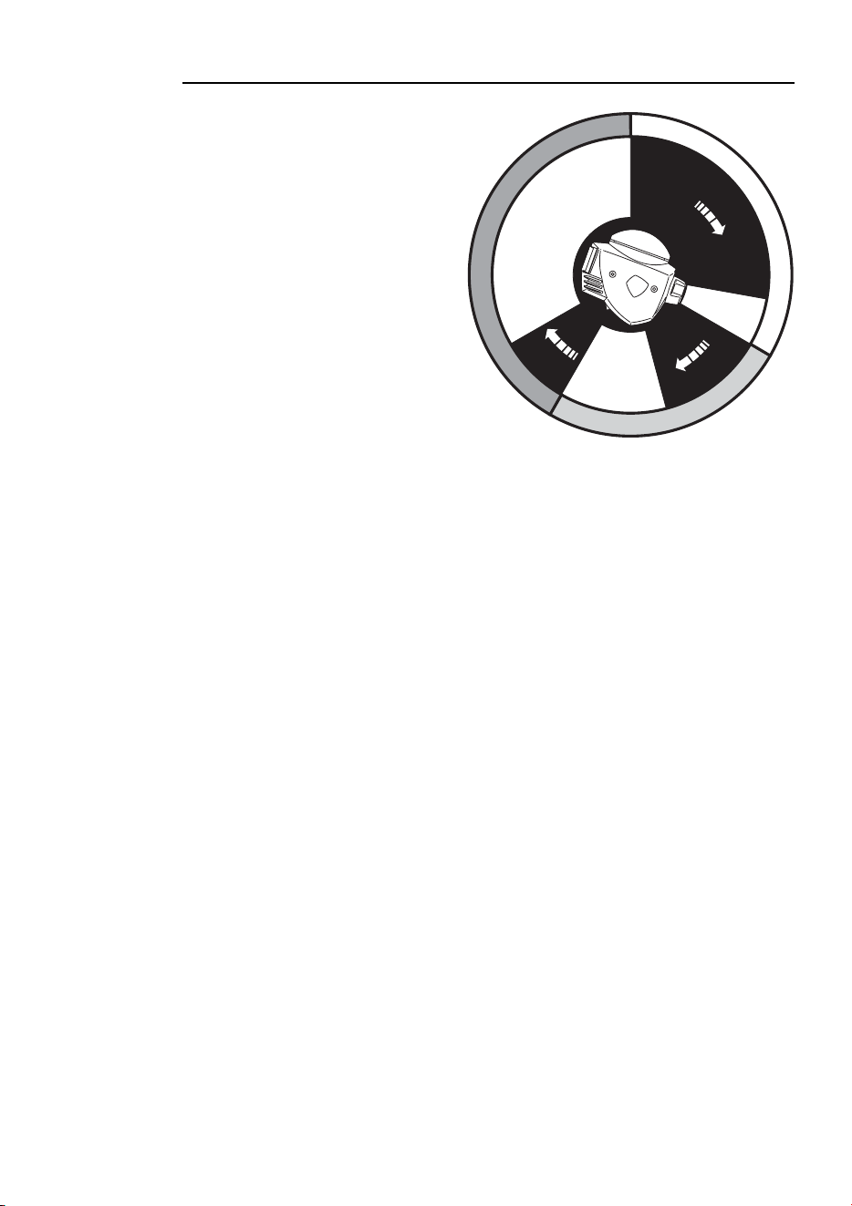
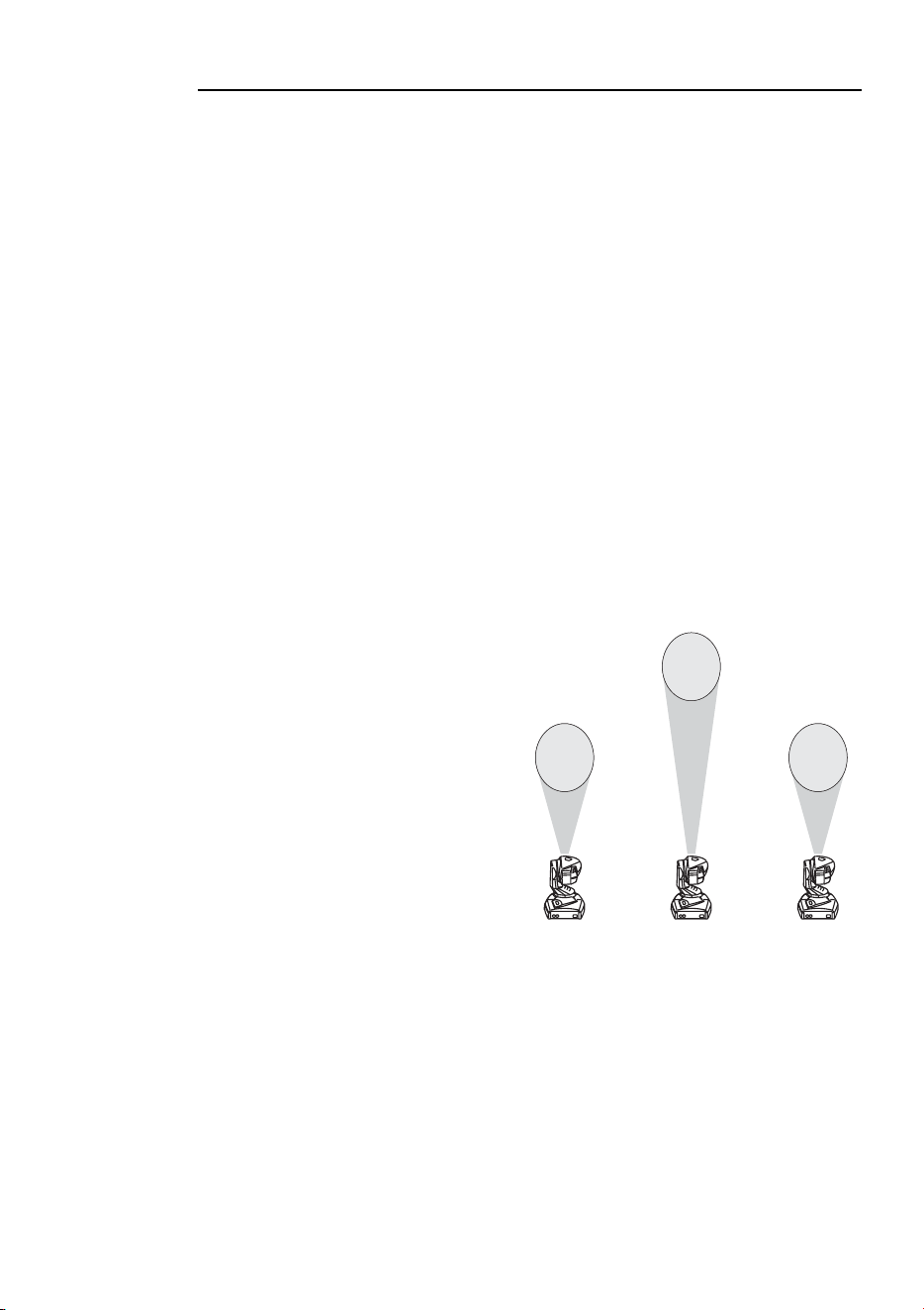
PROGRAMMING EXAMPLE
In the following example, three MiniMAC Maestros are programmed in IR Stand-
Alone Mode to project gobos that chase each other counterclockwise in a triangular
pattern.
SETUP
Setup three fixtures in a row and point them toward a wall. Insert the IR receiver in
the fixture on the right end as seen facing the wall from behind the fixtures. This
will be the master fixture; set it to
rCS mode and give it address 1.
Insert a data cable into the output of fixture 1 and connect it to the input of the
middle fixture. Set the middle fixture to
rCr and give it address 2. Insert a data
cable into the output of fixture 2 and connect it to the input of the third fixture. Set
the third fixture to
rCr and give it address 3.
From the control panel of each fixture, select Ctr/SCE/CLr and press [enter]
to delete all programming. Press [menu] a few times until the display reads
r00.
Point the remote control at the IR receiver and press the lamp power button.
SCENE 00
Press [ID] [1] to select fixture 1. Press
[Pan/Tilt] and position the beam at the
bottom-right corner of the triangle.
Press [Color/Gobo] and select a gobo
with [up] and [down]. Press
[Effect/Focus] and focus with [up] and
[down]. (Fine focus is available with
[left] and [right].) Press
[Rotating/Index] and rotate the gobo to
the desired angle with [left] and
[right]. Press [fade] [10] [wait] [5] to
set a fade time of 10 seconds and a
wait time of 5 seconds. Press [Store] to
save the settings to scene 00.
Press [ID] [2] and similarly set fixture 2 to project a gobo at the top of the triangle.
Set a fade time of 6 seconds and set the wait time to 4. Press [Store].
Select fixture 3 and focus a gobo at the bottom-left corner of the triangle. Set a fade
time of 7 seconds and set the wait time to 4. Press [Store].
1
2
3
36
Stand-alone operation
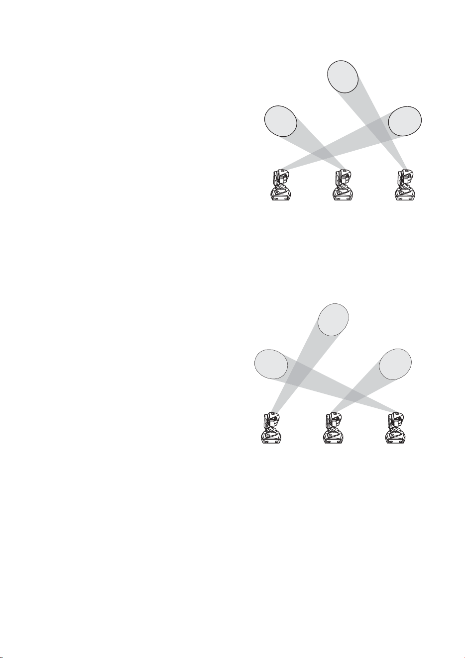
SCENE 01
Press [ID] [1] to select fixture 1. Press
[Pan/Tilt] and position the beam over
fixture 2’s beam at the top of the
triangle. Press [Effect/Focus] and
focus with [up] and [down]. Press
[Rotating/Index] and set the angle with
[left] and [right]. Press [Add] to create
and save the second scene with the
same fade and wait times as the first
scene.
Press [ID] [2] and similarly set fixture
2 to project over fixture 3 at the
bottom-left corner. Press [Add].
To use the same placement trick with fixture 3, first select fixture 1 and press [Prev]
to view scene r00. Then select and program fixture 3. Press [Add].
SCENE 02
Select fixture 1 and focus the gobo
in the bottom-left corner. Press
[Add]. Select fixture 2 and focus
the gobo in the bottom-right
corner. Press [Add]. Press [Prev]
[Prev] to scroll fixture 2 back to
scene r00 at the top of the triangle.
Focus fixture 3 at the top of the
triangle and press [Add].
EXECUTION
To run the sequence, press [ID] [1]
[2] [3] [Run/Stop]. During
execution the “r” in the display changes to a “P” on the master fixture and to an “S”
on the other fixtures.
2
1
3
1
2
3
Lamp
37
L
AMP
7
COMPATIBLE LAMPS
The MiniMAC Maestro is designed to use the Philips CDM-SA/T 150W discharge
lamp. Installing any other lamp may damage the fixture.
To replace the lamp
WARNING! Wear safety glasses and allow the lamp to cool for at least 5
minutes before opening the head.
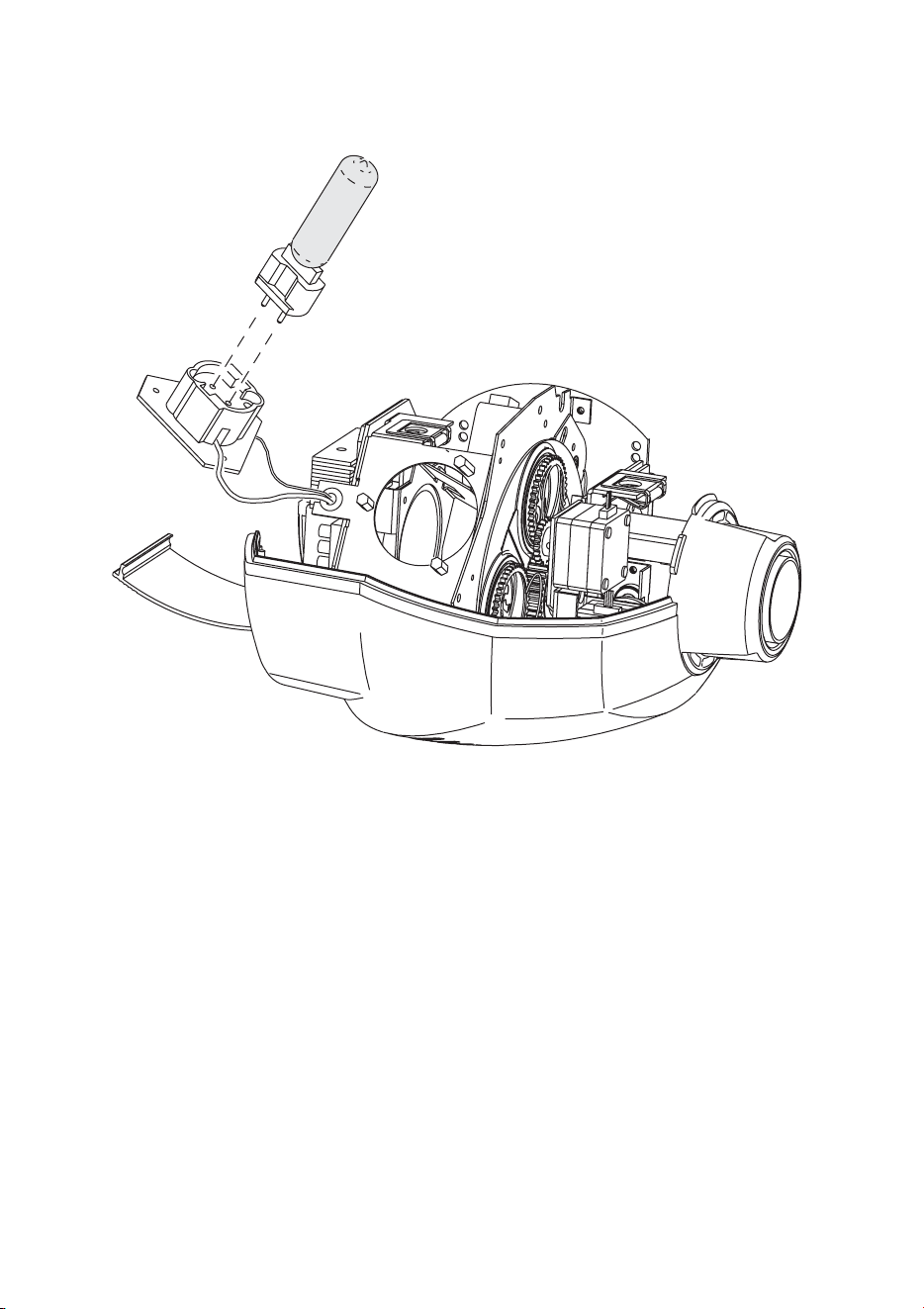
1 Disconnect the fixture from power and allow it to cool.
2 Pull open the rear cover.
3 Remove the 3 screws in the corners of the lamp base plate and remove the lamp
socket assembly.
Lamp Efficiency Color Temp. Average Life
Philips CDM-SA/T 150W 85 Lm/W 4000 K 6000 hr.
Table 5: Lamp specifications
38
Lamp
4 Remove the old lamp from the socket.
5 Holding the new lamp by its ceramic base (do not touch the glass), insert the lamp
squarely into the socket.
6 Clean the glass bulb with a clean, lint-free cloth wetted with alcohol.
7 Insert the lamp assembly and replace the screws. Replace the top cover and close
the rear cover before applying power.
8 Reset the lamp hour and lamp strike counters as described on page 20.

Gobos
39
G
OBOS
8
The MiniMAC Maestro holds up to four size-E gobos. For correct projection, install
gobos with the true side of the image facing the lamp.
CUSTOM GOBOS
The MiniMAC Maestro accepts glass, steel, and aluminum gobos with the
following dimensions (size-E). For best performance, the image should be true on
the coated side of glass gobos.
Outside gobo diameter: . . . . . . . . . . . . . . . . . . . . . . 37.5 +0/-0.3 mm (1 15/32 +0/-0.01 in.)
Maximum image diameter. . . . . . . . . . . . . . . . . . . . . . . . . . . . . . . . . . . . .30 mm (1 3/16 in.)
Maximum gobo thickness . . . . . . . . . . . . . . . . . . . . . . . . . . . . . . . . . . . . . . . . 3 mm (1/8 in.)
IMAGE SIZE
The focal length of the MiniMAC Maestro is 90 mm (3.54 in). To calculate the size
of a projected image using a gobo of a given size, the formula is
To calculate the gobo image size required to achieve a projected image size, the
formula is
projected image size
gobo image size projected distance×
focal length
----------------------------------------------------------------------------------------=
gobo image size
projected size focal length×
projected distance
--------------------------------------------------------------------=
40
Gobos
INSTALLATION
To install gobos
1 Turn off the lamp and allow it to cool for
at least 5 minutes. Disconnect the
fixture from power.
2 Unlock the head cover fasteners by
turning them a quarter-turn
counterclockwise. Open the rear cover
and then lift off the head cover.
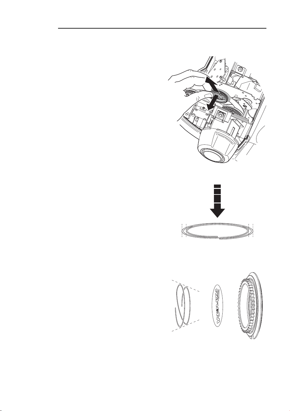
3 Turn the gobo wheel as required to
access the desired position. Pull the
gobo holder away from the wheel
slightly to release. Remove the gobo
holder.
4 Remove the gobo retention spring from
the holder and drop out the old gobo.
Insert the new gobo into the holder
true-side-first.
5 Identify the narrow end of the retention
spring by pressing it spring flat: the
narrow end is on the inside.
6 Insert the spring with the narrow end
against the gobo. Push the end of the
spring in under the lip of the holder.
7 Work the rim of the gobo holder under
both clips and snap the gobo holder
back into position. If necessary, a small
screwdriver or similar tool may be used
to pry the clips open.
8 Replace and close the head covers
before applying power.
Flatten spring to find narrow
end. Insert spring with narrow
end against reversed side of
gobo.

Gobos
41
SUGGESTED SUPPLIERS
The following companies can supply quality custom gobos from your artwork.
Apollo Design Technology, Inc.
E-mail: sales@internetapollo.com
Internet: www.internetapollo.com
Telephone: +1 (219) 497-9191
Fax: +1 (219) 497-9192
Beacon AB
E-mail: [email protected]
Internet: www.beacon.nu
Telephone: +46 (0) 90-715830
Fax: +46 (0) 90-710058
DHA Lighting Ltd.
E-mail: [email protected]
Internet: www.dhalighting.co.uk
Telephone: +44 020-7771-2900
Fax: +44 020-7771-2944
Rosco
E-mail: [email protected]
Internet: www.rosco.com
Telephone: +44 (0) 208-659-2300 (Europe)
+1 (866) 228-2256 (USA)
Fax: +44 (0) 208-659-3153 (Europe)
+1 (512) 388-0196 (USA)
Apo
ll
o Design Tec
h
no
l
ogy, Inc.
manufactures stainless steel and
glass gobos in custom or standard
designs. BW SuperResolution and
ColourScenic gobos feature 10,000
dpi resolution. Dichroic filters, tex-
tured dichroics, and crushed dich-
roics also available.
Beacon manu
f
actures
high quality full color
and B/W customized
glass gobos. The
Beacon Gobo group
is spread throughout the world from Australia to
Argentina to ensure personal service with high
quality and fast delivery.
DHA Lig
h
ting Lt
d
., experience
d
manufacturers and suppliers of
custom gobos. Available in
monochrome and coloured
dichroic glass, or a variety of
metals including stainless steel
and aluminium. Predistortion
of images a speciality. Over 900 standard gobo
designs to choose from.
For more t
h
an two
decades Rosco
Laboratories has
been the world's
largest supplier of gobos and dichroic filters for the
entertainment industries. You are serviced from fully
staffed offices in seven countries around the world.

42
Basic service
B
ASIC
SERVICE
9
The MiniMAC Maestro requires simple routine maintenance. The schedule depends
heavily on the operating environment; please consult a Martin service technician for
recommendations.
Refer all service not described here to a qualified Martin technician.
Important! Excessive dust, grease, and smoke fluid buildup degrades
performance and causes overheating and damage to the fixture
that is not covered by the warranty.
Warning! Disconnect the fixture from power before removing any cover.
CLEANING
To open the head
1 Disconnect the fixture from power and allow it to cool. Unlock the head cover
fasteners by turning them a quarter-turn counterclockwise. Open the rear cover by
pulling from the ribbed end.
2 Pull off the top head cover.
3 When replacing the cover, turn the fasteners a half to a quarter turn clockwise until
they click. Do not overtighten.
To clean optical components
Use care when cleaning optical components. The surfaces are fragile and small
scratches may be visible.
1 Disconnect the fixture from power and allow it to cool. Remove the head cover.
2 Blow or vacuum away loose dust. Remove residues from lenses with a soft cloth or
cotton swabs wetted with isopropyl alcohol. Regular glass cleaner may also be used,
but no residues may remain.
3 Rinse with distilled water. Mixing the water with a small amount of wetting agent such
as Kodak Photoflo will help prevent streaking and spotting.
4 Dry with a clean, soft and lint-free cloth or blow dry with compressed air.

Basic service
43
To clean the fan and air vents
Important! Neglecting to clean the fans and air vents can result in damage
to the fixture that is not covered by the warranty. Dust, smoke,
and grease buildup reduce the cooling air flow and will cause
the fixture to overheat. When the fixture overheats, a thermo
switch cuts power to the lamp until the fixture cools, and the
lamp cycles on and off at regular intervals.
To maintain sufficient cooling and air flow, inspect the air vents and fans at least
every 3 months or 1000 hours of operation and clean the fan and air vents by
removing dust and dirt from the fans and vent grills using a soft brush, cotton swab,
vacuum, or compressed air.
INSTALLING SOFTWARE
Firmware updates are released when features are added. The latest version is
available from the Support Area of the Martin Professional web site at
http://www.martin.dk. Firmware is installed using a Martin MP-2 uploader.
Important! Fixtures must be in a DMX mode and the data link must be
terminated.
To install software, normal method
1 Download the latest control software from the Martin Professional web site at
http://www.martin.dk. Install the software in a Martin MP-2 uploader.
2 Connect the uploader to the fixture as you would a controller. Apply power to the
uploader and the fixtures.
3 After the fixture has finished resetting, initiate the software upload as described in the
uploader manual. Wait.
4 When the upload is successfully completed, the fixture displays the new version
number and resets. Disconnect the upload device.
5 If a check-sum error (
CSE) occurs and/or the fixture does not reset, data was
interrupted or corrupted during transmission. Reattempt the upload using backup
method I, or try this procedure again.
To install software, backup method I
Follow this procedure exactly as described to install software if a normal upload
attempt is unsuccessful and a check-sum error (
CSE) occurs.
1 Disconnect the fixture from power: it must be off at least 10 seconds. Do not apply
power to the fixture until the uploader is connected and ready.
2 Connect the MP-2 uploader to the fixture as you would a controller. Terminate
the link.
3 Prepare the uploader for a boot mode upload but do not initiate the upload.
4 Apply power to the fixture. The control panel displays
CSE, then bSL, then b.
When
b is displayed, wait 5 seconds and then initiate the software upload from
the uploader. Wait.
5 When the upload is successfully completed, the fixture displays the new version
number and resets. Disconnect the upload device.
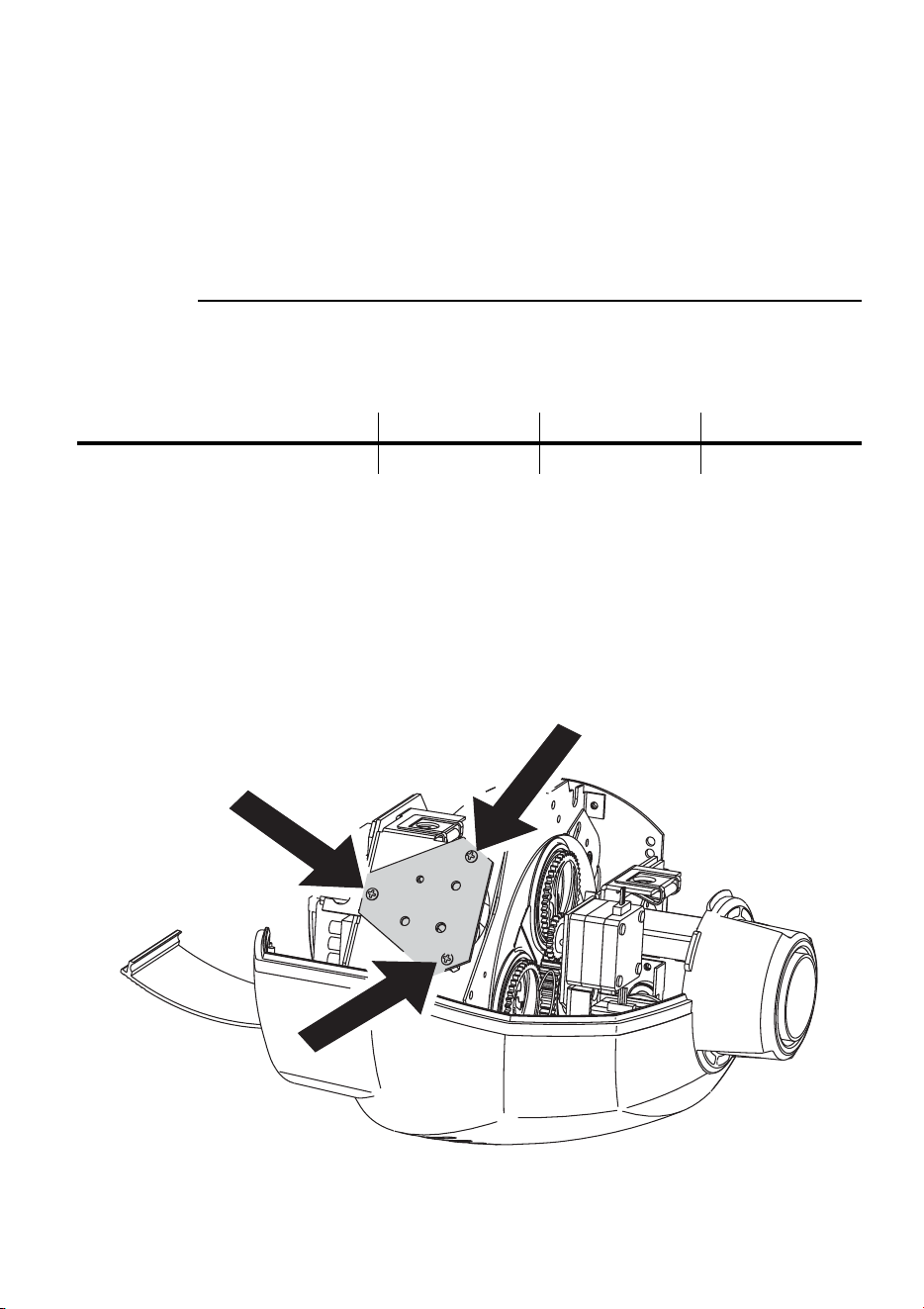
To install software, backup method II
Use this procedure to install software only if all else fails.
1 Disconnect the fixture from the data
link and power.
2 Use tweezers to move the jumper on
the main circuit board to the boot
setting.
3 Prepare the MP-2 uploader for a boot
mode upload but do not initiate the
upload.
4 Connect the MP-2 uploader to the fixture as you would a controller. Terminate
the link.
5 Apply power to the fixture and wait 5 seconds. Initiate the software upload from
the uploader. Wait.
6 When the upload is successfully completed, the fixture displays the new version
number and resets. Disconnect the MP-2 upload device. Disconnect the fixture
from power and move the jumper back to the normal setting.
REPLACING FUSES
Warning! Never replace fuses with ones of a different rating!
To replace the main fuse
1 Unplug the mains cable from the input socket. Pry open the fuse holder and
remove the fuse.
2 Replace the fuse with one of the same type. The fuse rating is listed on serial
number label and in the specifications.
boot settingnormal setting

Basic service
45
To replace secondary fuses
1 Disconnect the fixture from power.
2 Remove the 4 base cover bolts. Move the cover without disconnecting wires.
3 Pry out the defective fuse and replace it with one of the same rating.
4 Replace the cover before applying power.
INSERTING OR CHANGING A COLOR
FILTER
The MiniMAC Maestro has a spring clip in front of the gobo wheel that can accept
a fixed color filter. There is not much room to insert or remove the filter and this
procedure must be performed by an authorized Martin dealer. A list of available
filters can be found in “Dichroic color filters” on page 51.
46
Troubleshooting
T
ROUBLESHOOTING
10
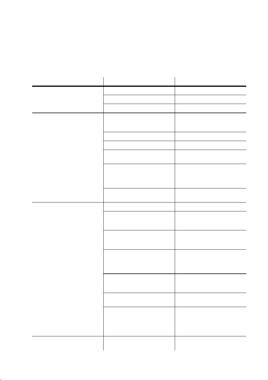
Problem Probable cause(s) Remedy
No response from fixture when
power is applied.
No power to fixture. Check power cables.
Primary fuse blown. Replace fuse.
Secondary fuse blown. Replace fuse.
No response to IR remote
control.
Remote control not pointed at
receiver or signal is blocked.
Point remote directly at
receiver from an unobstructed
position.
Backwards IR receiver. Flip and turn receiver arm.
No signal from remote. Replace batteries in remote.
Commands ignored during
execution.
Stop scene execution.
Fixture connected to a data
link that is using a DMX
protocol. This jams the IR
signal.
Remove the fixture from the
link.
Improper setup.
Verify protocol (rCr or rCS)
and address settings.
Fixture resets but does not
respond correctly to controller
(DMX mode operation).
Controller not connected. Connect controller.
Incorrect addressing of the
fixtures.
Check address and mode
settings on fixture and
controller.
Controller pin-out does not
match fixture pin-out (signal
reversed).
Insert a swapper cable in data
input.
Stand-alone mode enabled.
Verify that DMX address is
displayed at top of menu. If
not, disable stand-alone
mode.
Bad data link connection.
Inspect cables and correct
poor connections and/or
broken cables.
Data link not terminated.
Insert termination plug in
output of last fixture.
Defective fixture or 2 devices
transmitting on link.
Bypass fixtures one at a time
until normal operation is
regained: unplug both
connectors and connect them
directly together.
Fixture does not reset. An effect requires adjustment.
Try again. If problem persists,
contact service technician.
Troubleshooting
47
No light.
Lamp missing or blown.
Disconnect fixture and replace
lamp.
Shutter may be closed. Open the shutter.
Lamp cuts out intermittently or
burns out too quickly.
Fixture is too hot. Allow fixture to cool.
Incorrect power supply setting. Check setting.
Fans or air vents may be
blocked.
Clear/clean air vents and fan.
StE (memory error)
message displayed
The user settings cannot be
read from memory.
Contact service technician.
PAE (pan error time-out)
message displayed
Pan reset switch malfunction. Contact service technician.
TIE (tilt error time-out)
message displayed
Tilt reset switch malfunction. Contact service technician.
CSE (check-sum error)
message displayed
Unsuccessful software upload. See “Installing software”.
Shaky movement during
combined pan/tilt movement
Movement occurs at a
resonant velocity.
Make small adjustment to fade
path or fade time.
Controller has poor DMX
tracking.
Use the speed channel and
avoid controller fading.
Problem Probable cause(s) Remedy
48
DMX protocol
DMX
PROTOCOL
A
1234 Value Percent Function
1
0 - 19
20 - 49
50 - 112
113 - 127
128 - 137
138 - 147
148 - 157
158 - 207
208 - 217
218 - 227
228 - 237
238 - 247
248 - 255
0 - 7
7 - 19
19 - 44
44 - 50
50 - 53
54 - 57
58 - 61
62 - 81
81 - 85
85 - 87
89 - 93
93 - 97
97 - 100
Shutter, Strobe, Reset, Lamp On/Off
Shutter closed
Shutter open
Strobe, fast to slow
Shutter open
Random strobe, fast
Random strobe, medium
Random strobe, slow
Shutter open
*Reset
Shutter open
Lamp on
Shutter open
*Lamp off: hold for 5 seconds
2
0 - 19
20 - 39
40 - 59
60 - 79
80 - 99
100 -119
120 - 139
140 - 159
160 - 198
199 - 255
0 - 7
7 - 15
15 - 23
23 - 31
31 - 39
39 - 46
47 - 54
55 - 62
63 - 78
78 -100
Image Selection
Image 1, indexed rotation
Image 2, indexed rotation
Image 3, indexed rotation
Image 4, indexed rotation
Image 1, continuous rotation
Image 2, continuous rotation
Image 3, continuous rotation
Image 4, continuous rotation
Clockwise wheel rotation, slow to fast
Counterclockwise rotation, fast to slow
3
0 - 255
0 - 2
3 - 127
128 - 252
253 - 255
0 - 100
0
1 - 50
50 - 99
99 - 100
Image Rotation (select image on ch. 3)
Coarse position index (MSB), Min Æ Max
Rotation velocity
No rotation
CW rotation, slow to fast
CCW rotation, fast to slow
No rotation
-4-4
0 - 255 0 - 100
Image Rotation, Fine Position
Fine position index (LSB), Min Æ Max
4545
0 - 255 0 - 100
Focus
Infinity Æ near
* If disabled, confirm with
image 4 and close focus.
DMX protocol
49
5656
0 - 255 0-100
Pan
Left to right (128 = neutral)
-7-7
0 - 255 0-100
Pan fine (LSB)
Left to right
6868
0 - 255 0-100
Tilt
Up to down (128 = neutral)
-9-9
0 - 255 0-100
Tilt fine (LSB)
Up to down
--710
0 - 2
3 - 245
246 - 248
249 - 251
252 - 255
0
1 - 96
96 - 97
98
99 - 100
Pan/Tilt Speed
Tracking mode
Fast to slow
Tracking,
PtS=SLO
Tracking,
PtS=FSt
Blackout while moving
--811
0 - 2
3 - 251
252 - 255
0
1 - 96
97 - 100
Image and Focus Speed
Tracking mode
Fast to slow
Blackout while moving
1234 Value Percent Function

50
Specifications
S
PECIFICATIONS
B
PHYSICAL
Length: . . . . . . . . . . . . . . . . . . . . . . . . . . . . . . . . . . . . . . . . . . . . . . . . . . 390 mm (15.4 in)
Width: . . . . . . . . . . . . . . . . . . . . . . . . . . . . . . . . . . . . . . . . . . . . . . . . . . 316 mm (12.4 in)
Height: . . . . . . . . . . . . . . . . . . . . . . . . . . . . . . . . . . . . . . . . . . . . . . . . . . 415 mm (16.3 in)
Weight: . . . . . . . . . . . . . . . . . . . . . . . . . . . . . . . . . . . . . . . . . . . . . . . . . 14.0 kg (30.8 lbs)
SOURCE
Philips CDM “Master Color” 150 W (included) . . . . . . . . . . 85 Lm/W, 6000 hr., 4000 K
OPTICS
Focused beam angle: . . . . . . . . . . . . . . . . . . . . . . . . . . . . . . . . . . . . . . . . . . . . . . . . . . 19°
Focal length: . . . . . . . . . . . . . . . . . . . . . . . . . . . . . . . . . . . . . . . . . . . . . . . . . . . . . . .90 mm
Focus range: . . . . . . . . . . . . . . . . . . . . . . . . . . . . . . . . . . . . . . . . . 1 m (3.2 ft.) to infinity
DATA COMMUNICATION
Hardware standard: . . . . . . . . . . . . . . . . . . . . . . . . . . . . . . . . . . . . . . . . . . . . . . . . RS-485
Data I/O: . . . . . . . . . . . . . . locking 3-pin XLR, pin 1 shield, pin 2 cold (-), pin 3 hot (+)
Recommended cable: 24 AWG (min.), low capacitance, 85-150 Ω shielded twisted pair
INSTALLATION
Mounting points: . . . . . . . . . . . . . . . . . . . . . . . . . . . . . . . . . . . . . .1 pair of 1/4-turn locks
Orientation: . . . . . . . . . . . . . . . . . . . . . . . . . . . . . . . . . . . . . . . . . . . . . . . . . . . . . . . . . any
Minimum distance to combustible materials: . . . . . . . . . . . . . . . . . . . . . . . .0.3 m (12 in)
Minimum distance to illuminated surfaces: . . . . . . . . . . . . . . . . . . . . . . . . .0.3 m (12 in)
Minimum clearance around fan and air vents: . . . . . . . . . . . . . . . . . . . . . . . . 0.1 m (4 in)
THERMAL
Maximum ambient temperature (Ta): . . . . . . . . . . . . . . . . . . . . . . . . . . . . . . 40° C (104° F)
Maximum surface temperature: . . . . . . . . . . . . . . . . . . . . . . . . . . . . . . . . . . . 55° C (131° F)
AC SUPPLY
AC input: . . . . . . . . . . . . . . . . . . . . . . . . . . . . . . . . . . . . . . . . . . . . . . 3-pin IEC male socket
Power supply options: . . . . . . . . . . . 100/120/210/230/250 V, 50/60 Hz (switch-selectable)
MAXIMUM POWER AND CURRENT
100 V, 50 or 60 Hz: . . . . . . . . . . . . . . . . . . . . . . . . . . . . . . . . . . . . . . . . . . . . . .260 W, 3.0 A
120 V, 50 or 60 Hz: . . . . . . . . . . . . . . . . . . . . . . . . . . . . . . . . . . . . . . . . . . . . . .265 W, 2.5 A
210 V, 50 or 60 Hz: . . . . . . . . . . . . . . . . . . . . . . . . . . . . . . . . . . . . . . . . . . . . . .245 W, 1.4 A
230 V, 50 or 60 Hz: . . . . . . . . . . . . . . . . . . . . . . . . . . . . . . . . . . . . . . . . . . . . . .250 W, 1.2 A
250 V, 50 or 60 Hz: . . . . . . . . . . . . . . . . . . . . . . . . . . . . . . . . . . . . . . . . . . . . . .255 W, 1.1 A

Specifications
51
FUSES
Primary fuse: . . . . . . . . . . . . . . . . . . . . . . . . . . . . . . . . . . . . . . . . T 3.15 A, high I2t, 250 V
Fuse F401: . . . . . . . . . . . . . . . . . . . . . . . . . . . . . . . . . . . . . . . . . . T 3.15 A, high I2t, 250 V
Fuse F402: . . . . . . . . . . . . . . . . . . . . . . . . . . . . . . . . . . . . . . . . . . . . . . . . . . .T 2.5 A, 250 V
CONSTRUCTION
Housing: . . . . . . . . . . . . . . . . . . . . . . . . . . . . . . . . . UV-resistant fiber-reinforced composite
Finish: . . . . . . . . . . . . . . . . . . . . . . . . . . . . . . . . . . . . . . . . . . . . . . . . . . polyurethane coating
Protection factor: . . . . . . . . . . . . . . . . . . . . . . . . . . . . . . . . . . . . . . . . . . . . . . . . . . . . . IP 20
ACCESSORIES
Martin infrared remote control transmitter . . . . . . . . . . . . . . . . . . . . . . . . . . . P/N 90760010
Martin infrared remote control receiver . . . . . . . . . . . . . . . . . . . . . . . . . . . . . P/N 91611047
2-unit flight case . . . . . . . . . . . . . . . . . . . . . . . . . . . . . . . . . . . . . . . . . . . . . . . P/N 91510007
G-clamp: . . . . . . . . . . . . . . . . . . . . . . . . . . . . . . . . . . . . . . . . . . . . . . . . . . . . . P/N 91602003
Half-coupler clamp: . . . . . . . . . . . . . . . . . . . . . . . . . . . . . . . . . . . . . . . . . . . . P/N 91602005
Pantograph. . . . . . . . . . . . . . . . . . . . . . . . . . . . . . . . . . . . . . . . . . . . . . . . . . . . P/N 91602006
Flush mount bracket . . . . . . . . . . . . . . . . . . . . . . . . . . . . . . . . . . . . . . . . . . . . P/N 91606009
DICHROIC COLOR FILTERS
Light blue 101 . . . . . . . . . . . . . . . . . . . . . . . . . . . . . . . . . . . . . . . . . . . . . . . . . P/N 46401601
Flame red 304 . . . . . . . . . . . . . . . . . . . . . . . . . . . . . . . . . . . . . . . . . . . . . . . . . P/N 46401602
Fern green 205. . . . . . . . . . . . . . . . . . . . . . . . . . . . . . . . . . . . . . . . . . . . . . . . . P/N 46401603
Yellow 603. . . . . . . . . . . . . . . . . . . . . . . . . . . . . . . . . . . . . . . . . . . . . . . . . . . . P/N 46401604
Light green 204 . . . . . . . . . . . . . . . . . . . . . . . . . . . . . . . . . . . . . . . . . . . . . . . . P/N 46401605
Pink 312. . . . . . . . . . . . . . . . . . . . . . . . . . . . . . . . . . . . . . . . . . . . . . . . . . . . . . P/N 46401606
Primary green 206 . . . . . . . . . . . . . . . . . . . . . . . . . . . . . . . . . . . . . . . . . . . . . . P/N 46401607
Amber 604 . . . . . . . . . . . . . . . . . . . . . . . . . . . . . . . . . . . . . . . . . . . . . . . . . . . . P/N 46401608
Orange 306 . . . . . . . . . . . . . . . . . . . . . . . . . . . . . . . . . . . . . . . . . . . . . . . . . . . P/N 46401609
Deep orange. . . . . . . . . . . . . . . . . . . . . . . . . . . . . . . . . . . . . . . . . . . . . . . . . . . P/N 46401610
Primary red 308 . . . . . . . . . . . . . . . . . . . . . . . . . . . . . . . . . . . . . . . . . . . . . . . . P/N 46401611
Magenta 507 . . . . . . . . . . . . . . . . . . . . . . . . . . . . . . . . . . . . . . . . . . . . . . . . . . P/N 46401612
Lavender 508 . . . . . . . . . . . . . . . . . . . . . . . . . . . . . . . . . . . . . . . . . . . . . . . . . . P/N 46401613
Dark blue 107 . . . . . . . . . . . . . . . . . . . . . . . . . . . . . . . . . . . . . . . . . . . . . . . . . P/N 46401614
Medium blue . . . . . . . . . . . . . . . . . . . . . . . . . . . . . . . . . . . . . . . . . . . . . . . . . . P/N 46401615
Turquoise 202 . . . . . . . . . . . . . . . . . . . . . . . . . . . . . . . . . . . . . . . . . . . . . . . . . P/N 46401616
Blue 104. . . . . . . . . . . . . . . . . . . . . . . . . . . . . . . . . . . . . . . . . . . . . . . . . . . . . . P/N 46401617
Purple. . . . . . . . . . . . . . . . . . . . . . . . . . . . . . . . . . . . . . . . . . . . . . . . . . . . . . . . P/N 46401618
CTC 5500-3400K . . . . . . . . . . . . . . . . . . . . . . . . . . . . . . . . . . . . . . . . . . . . . . P/N 46401619
CTC 3500-5600K . . . . . . . . . . . . . . . . . . . . . . . . . . . . . . . . . . . . . . . . . . . . . . P/N 46401620
UV-transmitter . . . . . . . . . . . . . . . . . . . . . . . . . . . . . . . . . . . . . . . . . . . . . . . . . P/N 46401621
Green 201 . . . . . . . . . . . . . . . . . . . . . . . . . . . . . . . . . . . . . . . . . . . . . . . . . . . . P/N 46401622
