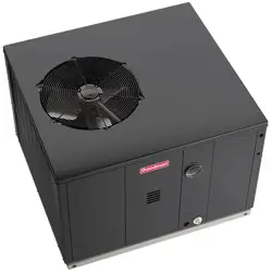
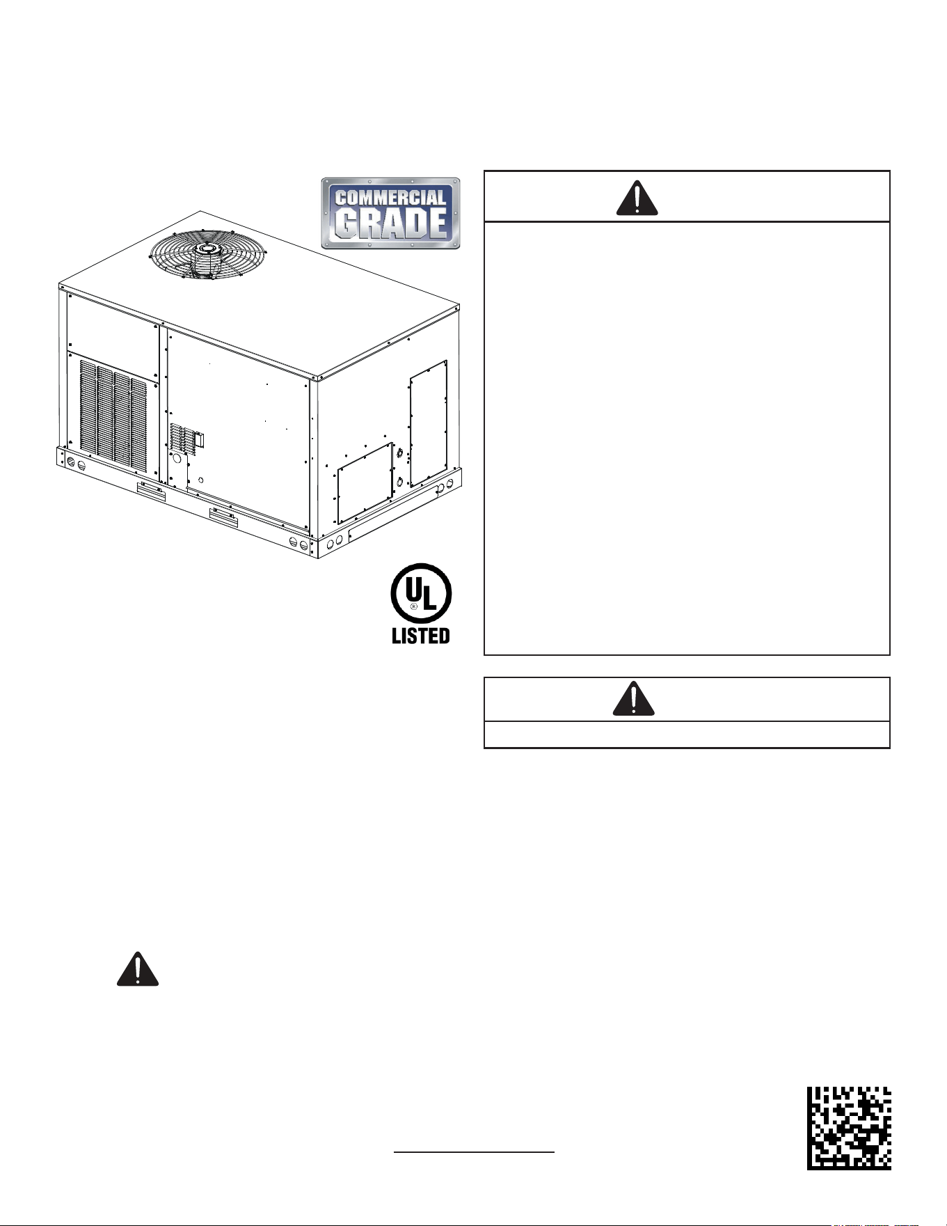
IOG-3041A
04/2025
Our continuing commitment to quality products may mean a change in specications without notice.
Daikin Comfort Technologies Manufacturing, Inc.
19001 Kermier Rd., Waller, TX 77484
www.goodmanmfg.com
© 2024, 2025 Daikin Comfort Technologies Manufacturing, Inc.
Ax this manual and Users Information
Manual adjacent to the unit.
WARNING
Do not bypass safety devices.
Only personnel that have been trained to install, adjust,
service, maintenance or repair (hereinafter, “service”)
the equipment specified in this manual should service the
equipment.
This equipment is not intended for use by persons
(including children) with reduced physical, sensory or
mental capacities, or lack of experience and knowledge,
unless they have been given supervision or instruction
concerning use of the appliance by a person responsible
for their safety.
Children should be supervised to ensure that they do not
play with the equipment.
The manufacturer will not be responsible for any injury
or property damage arising from improper supervision,
service or service procedures. If you service this unit, you
assume responsibility for any injury or property damage
which may result. In addition, in jurisdictions that require
one or more licenses to service the equipment specified in
this manual, only licensed personnel should service the
equipment. Improper supervision, installation, adjustment,
servicing, maintenance or repair of the equipment specified
in this manual, or attempting to install, adjust, service
or repair the equipment specified in this manual without
proper supervision or training may result in product
damage, property damage, personal injury or death.
WARNING
ATTENTION INSTALLING PERSONNEL:
Prior to installation, thoroughly familiarize yourself with this
Installation Manual. Observe all safety warnings. During
installation or repair, caution is to be observed.
It is your responsibility to install the product safely and to
educate the customer on its safe use.
RECOGNIZE THIS SYMBOL
AS A SAFETY PRECAUTION
These installation instructions cover the outdoor
installation of single package heating and cooling units.
See the Specication Sheet applicable to your model for
information regarding accessories.
NOTE: Please contact your distributor or our
website for the applicable Specification Sheet
referred to in this manual.
This Forced Air Central Unit Design complies with re
quirements embodied in The American National Standard /
National Standard of Canada shown below:
ANSI Z21.47 / CSA-2.3 Gas-Fired Central Furnaces
NOTE: This equipment is only approved for use with
R-32 refrigerant.
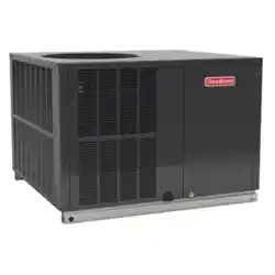
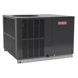
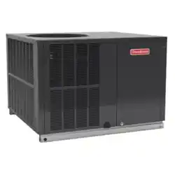
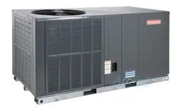
Packaged Gas/Electric Heating & Cooling 5 Ton Units
GPGM5 15.2 SEER2 “M” Series with R-32
Installation Instructions
2
TABLE OF CONTENTS
Safety Instructions ...................................................... 2
Parts and Accessories ................................................. 4
General Information .................................................... 5
Unit Location .................................................................. 6
Clearances ..................................................................... 8
Roof Curb Post-Installation checks ........................ 9
Roof Top Duct Connections ........................................ 9
Rigging Details ............................................................. 9
Weights and Center of Gravity ................................ 10
Electrical wiring ........................................................ 10
Gas Supply Piping ....................................................... 13
Propane Gas Installations ........................................ 14
Circulating Air and Filters ....................................... 15
Condensate Drain Connection ................................. 16
Startup, Adjustments, and Checks .......................... 16
Air flow Adjustments ................................................ 17
Gas System Check ....................................................... 18
Normal Sequence Of Operation ............................... 22
Maintenance ................................................................. 25
Troubleshooting ......................................................... 27
Appendix A Blower Performance Tables ............... 31
Appendix C Unit dimensions ....................................... 32
Appendix D Min-Max Airflow ..................................... 33
Wiring Diagram ............................................................ 34
Startup Checklist ....................................................... 35
SAFETY INSTRUCTIONS
To The Installer
Before installing this unit, please read this manual to
familiarize yourself on the specic items which must be
adhered to, including maximum external static pressure to
unit, air temperature rise, minimum or maximum CFM and
motor speed connections.
Keep this literature in a safe place for future reference.
WARNING
If the information in these instructions is not followed
exactly, a fire or explosion may result causing property
damage, personal injury or loss of life.
- do not store or use gasoline or other flammable vapors
and liquids in the vicinity of this or any other appliance.
- WHAT TO DO IF YOU SMELL GAS:
• Do not try to light any appliance.
• Do not touch any electrical switch; do not use any
phone in your building.
• Immediately call your gas supplier from a neighbor’s
phone. Follow the gas supplier’s instructions. If
you cannot reach your gas supplier, call the fire
department.
- Installation and service must be performed by a qualified
installer, service agency or the gas supplier.
WARNING
FIRE HAZARD
Should overheating occur or the gas supply fail to shut
off, turn off the manual gas shutoff valve external to the
furnace before turning off the electrical supply.
WARNING
To prevent the risk of property damage, personal injury, or
death, do not store combustible materials or use gasoline
or other flammable liquids or vapors in the vicinity of this
appliance.
CAUTION
Sheet metal parts, screws, clips and similar items inherently
have sharp edges, and it is necessary that the installer and
service personnel exercise caution.
WARNING
Do not connect to or use any device that is not certified by
the manufacturer for use with this unit. Serious property
damage, personal injury, reduced unit performance and/or
hazardous conditions may result from the use of such non-
approved devices.
WARNING
To avoid property damage, personal injury or death, do not
use this unit if any part has been under water. Immediately
call a qualified service technician to inspect the furnace
and to replace any part of the control system and any gas
control having been under water.
WARNING
This unit must not be used as a “construction heater” during
the finishing phases of construction on a new structure.
This type of use may result in premature failure of the unit
due to extremely low return air temperature and exposure
to corrosive or very dirty atmospheres.
3
WARNING
Heating unit should not be utilized without reasonable,
routine, inspection, maintenance and supervision. If the
building in which any such device is located will be vacant,
care should be taken that such device is routinely inspected,
maintained and monitored. In the event that the building may
be exposed to freezing temperatures and will be vacant, all
water-bearing pipes should be drained, the building should
be properly winterized, and the water source closed.
In the event that the building may be exposed to freezing
temperatures and will be vacant, any hydronic coil units
should be drained as well and, in such case, alternative heat
sources should be utilized.
WARNING
HIGH VOLTAGE!
Disconnect all power before servicing or
installing this unit. Multiple power sources
may be present. Failure to do so may cause
property damage, personal injury or death.
WARNING
Do not use means to accelerate the defrosting process or to
clean, other than those recommended by the manufacturer.
The appliance shall be stored in a room without
continuously operating ignition sources (for example: open
flames, an operating gas appliance or an operating electric
heater). Do not pierce or burn. Be aware that refrigerants
may not contain an odor.
WARNING
Only auxiliary devices approved by the appliance
manufacturer or declared suitable with the refrigerant
shall be installed in connecting ductwork.
WARNING
Auxiliary devices which may be a POTENTIAL IGNITION SOURCE
shall not be installed in the duct work. Examples of such
POTENTIAL IGNITION SOURCES are hot surfaces with a
temperature exceeding 700°C and electric switching devices.
WARNING
LEAK DETECTION SYSTEM installed. Unit must be powered
except for service.
WARNING
This unit is equipped with electrically powered safety
measures. To be effective, the unit must be electrically
powered at all times after installation, other than when
servicing.
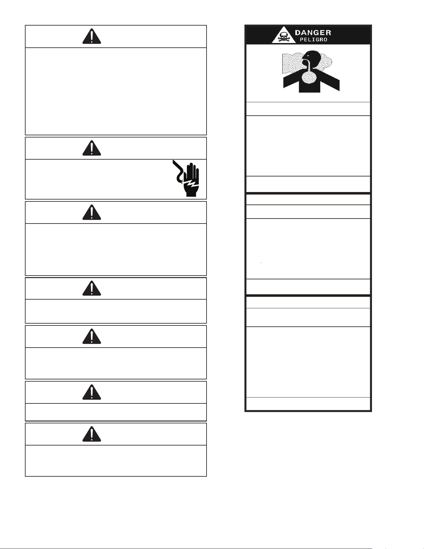
Carbon monoxide producing devices (such as an automobile, space
heater, gas water heater, etc.) should not be operated in enclosed areas
such as unvenlated garages, ulity rooms or parking areas because of
the danger of carbon monoxide (CO) poisoning resulng from the exhaust
emissions. If a furnace or air handler is installed in an enclosed area such
as a garage, ulity room or parking area and a carbon monoxide producing
device is operated therein, there must be adequate, direct outside
venlaon.
CARBON MONOXIDE POISONING HAZARD
Special Warning for In stallaon of Furnace or Air Handling Units in
Enclosed Areas such as Garages, Ulity Rooms or Parking Areas
This venlaon is necessary to avoid the danger of CO poisoning which
can occur if a carbon monoxide producing device connues to operate in
the enclosed area. Carbon monoxide emissions can be (re)circulated
throughout the structure if the furnace or air handler is operang in any
mode.
B10259-216
CO can cause serious illness including permanent brain
damage or death.
Los equipos ó aparatos que producen monóxido
(tal como automóvil, calentador de gas, calentador de
carbono (CO) que resulta de las
emisiones de gases de com busón.
gas, etc) no deben ser operados en áreas cerradas debido al riesgo
de envenenamiento por monóxido de
Si el equipo ó aparato se opera en
dichas áreas, debe exisr una adecuada venlación directa al exterior.
de carbono
agua por medio de
Advertencia especial para la instalación de calentadores ó manejadoras
de aire en áreas cerradas como estacionamientos ó cuartos de servicio.
B10259-216
RIESGO DE INTOXICACIÓN POR MONÓXIDO DE CARBONO
El monóxido de carbono puede causar enfermedades severas
como daño cerebral permanente ó muerte.
Las emisiones de monóxido de carbono pueden circular a través
del aparato cuando se opera en cualquier modo.
Averssement special au sujet de l'installaon d'appareils de chauffage
ou de traitement d'air dans des endroits clos, tets les garages, les
locaux d'entreen et les staonnements.
B10259-216
RISQUE D'EMPOISONNEMENT AUMONOXYDE DE CARBONE
Evitez de mere en marche les appareils produisant du monoxyde
de carbone (tels que les automobile, les appareils de chauffage
autonome,etc.) dans des endroits non venlés tels que les
d'empoisonnement au monoxyde de carbone. Si vous devez faire
fonconner ces appareils dans un endroit clos, assures-vous
qu'il y ait une venlaon directe provenant de l'exterier.
Le monoxyde de
des
carbone peut causer des maladies graves telles que
dommages permanents au cerveau et meme la mort.
Les émissions de monoxyde de carbone peuvent etre recircules dans les
endroits clos, si l'appareil de chauffage ou de traitement d'air sont
en marche.
Cee venlaon est nécessaire pour éviter le danger d'intoxicaon
au CO pouvant su rvenir si un appareil produisant du monoxyde
de carbone connue de fonconner au sein de la zo ne confinée.
Esta venlación es necesaria para evitar el peligro de envenenamiento
por CO, que puede ocurrir si un monóxido
de carbono sigue operando en el lugar cerrado .
disposivo que produc e
4
The following instructions are mandatory for A2L
systems and supersede other instructions
WARNING
Only brazing techniques or approved mechanical joints
should be used to connect refrigerant tubing connections.
Non-approved mechanical connectors and other methods
are not permitted in this system containing A2L refrigerant.
Approved mechanical joints will be detailed in the product’s
specification sheets.
Deep Vacuum Method
The Deep Vacuum Method requires a vacuum pump
rated for 500 microns or less. This method eectively and
eciently ensures the system is free of noncondensable
air and moisture. The Triple Evacuation Method is
detailed in the Service Manual for this product model as
an alternative. To expedite the evacuation procedure, it is
recommended that the Schrader Cores be removed from
the service valves using a coreremoval tool.
1. Connect the vacuum pump, micron gauge, and
vacuumrated hoses to both service valves.
Evacuation must use both service valves to eliminate
system mechanical seals.
2. Evacuate the system to less than 500 microns.
3. Isolate the pump from the system and hold the
vacuum for 10 minutes (minimum). Typically, pressure
will rise slowly during this period. If the pressure rises
to less than 1000 microns and remains steady, the
system is considered leak-free; proceed to system
charging and startup.
4. If pressure rises above 1000 microns but holds steady
below 2000 microns, noncondensable air or moisture
may remain, or a small leak may be present. Return
to step 2: If the same result is achieved, check for
leaks and repair. Repeat the evacuation procedure.
5. If pressure rises above 2000 microns, a leak is
present. Check for leaks and repair any leaks. Then,
repeat the evacuation procedure.
Accessory Installation
WARNING
All accessories that may become a potential ignition source
if installed, such as electronic air cleaners, must only be
powered through our accessory control board kit. If an
electronic air cleaner is already installed in the duct work
and not connected to the accessory control board, it will
have to be disabled or removed. Ensure that any additional
wiring from the indoor unit to the accessory control
board is routed and protected from damage and wear,
avoiding the flue pipe and any joints that may need brazed or
disconnected for service. Refer to the product specification
sheet for the accessory control board kit part number.
Altitude Adjustment Factor to Calculate Minimum
Room Area
The Indoor equipment mitigation requirements are
calculated at sea level. For higher altitudes adjust the
minimum room area specied on or near the Serial Plate
by the corresponding altitude adjustment factor shown
below. This table is provided as a reference.
Adjusted room area (A
min
adj
) is the product of the minimum
room area specied on the serial plate and the adjustment
factor AF, as shown in below formula.
A
min adj
= A
min
(serial plate) * AF
Altitude Adjustment Factor (AF)Height in feetHeight in meters
1.00At sea levelAt sea level
1.021~6601~200
1.03660~1320200~400
1.051320~1970400~600
1.071970~2630600~800
1.092630~3290800~1000
1.113290~39401000~1200
1.133940~46001200~1400
1.154600~52501400~1600
1.175250~59101600~1800
1.195910~65701800~2000
1.216570~72202000~2200
1.247220~78802200~2400
1.267880~85402400~2600
1.298540~91902600~2800
1.319190~98502800~3000
1.349850~105003000~3200
PARTS AND ACCESSORIES
Ordering Parts
When reporting shortages or damages, or ordering repair
parts, give the complete unit model and serial numbers as
stamped on the unit’s nameplate.
Replacement parts for this appliance are available through
your contractor or local distributor. Your nearest distributor
can be located online at https://partner.goodmanmfg.com
or by contacting:
5
HOMEOWNER SUPPORT
DAIKIN COMFORT
TECHNOLOGIES MANUFACTURING, L.P.
19001 KERMIER ROAD
WALLER, TEXAS 77484
(855) 7705678
Additional accessories can be purchased to t specic
application needs. Parts and instructions are also available
from your distributor.
Functional Parts
NOTE: Refer to the unit Parts Catalog when
ordering functional parts. Be sure to provide the
unit model and serial numbers with the order.
All sheet metal parts, doors, etc. may also be ordered by
their description.
GENERAL INFORMATION
WARNING
To prevent property damage, personal injury or death, due to
fire, explosions, smoke, soot, condensation, electric shock
or carbon monoxide, this unit must be properly installed,
repaired, operated, and maintained.
This unit is approved for outdoor installation ONLY.
Rated performance is achieved after 20 hours of operation.
Rated performance is delivered at the specied airow.
See product specication sheet for residential packaged
models. Specication sheets can be found at
www.goodmanmfg.com for Goodman brand products.
Within the website, please select the Products & Services
menu and then select the submenu for the type of product
to be installed, such as air conditioners or heat pumps, to
access a list of product pages that each contain links to
that model’s specication sheet.
To assure that your unit operates safely and eciently, it
must be installed, operated, and maintained in accordance
with these installation and operating instructions, all local
building codes and ordinances, or in their absence, with
the latest edition of the National Fuel Gas Code NFPA54/
ANSI Z223.1 and National Standard of Canada CAN/CSA
B149 Installation Codes.
Qualification of Workers
Personnel must be certied to service, work, and/or repair
units with FLAMMABLE REFRIGERANTS. A certicate
should document the competence and qualication
achieved through training that included the substance of
the following:
• Information about the explosion potential of
FLAMMABLE REFRIGERANTS to show that
ammables may be dangerous when handled without
care.
• Information about POTENTIAL IGNITION SOURCES,
especially those that are not obvious, such as lighters,
light switches, vacuum cleaners, electric heaters.
• Information about the dierent safety concepts,
including ventilated and unventilated areas.
• Information about refrigerant detectors, including
function, operation, and service measures.
• Information about the concept of sealed components
and sealed enclosures according to IEC 60079
15:2010.
• Information about the correct working procedures,
including commissioning, maintenance, repair,
decommissioning, and disposal procedures.
EPA Regulations
IMPORTANT: The United States Environmental
Protection Agency (EPA) has issued various
regulations regarding the introduction and
disposal of refrigerants in this unit. Failure
to follow these regulations may harm the
environment and can lead to the imposition of
substantial fines. Because regulations may vary
due to passage of new laws, we suggest a certified
technician perform any work done on this unit.
Should you have any questions please contact the
local office of the EPA.
National Codes
This product is designed and manufactured to permit
installation in accordance with National Codes. It is the
installer’s responsibility to install the product in accordance
with National Codes and/or prevailing local codes and
regulations.
The heating and cooling capacities of the unit should be
greater than or equal to the design heating and cooling
loads of the area to be conditioned. The loads should be
calculated by an approved method or in accordance with
ASHRAE Guide or Manual J Load Calculations published
by the Air Conditioning Contractors of America.
Obtain from:
American National Standards Institute
25 West 43rd Street, 4th Floor
New York, NY 10036
System design and installation should also, where
applicable, follow information presented in accepted industry
guides such as the ASHRAE Handbooks. The manufacturer
assumes no responsibility for equipment installed in violation
of any code or regulation. The mechanical installation of the
packaged roof top units consists of making nal connections
between the unit and building services; supply and return
duct connections; and drain connections (if required). The
internal systems of the unit are completely factory-installed
and tested prior to shipment.
6
Units are generally installed on a steel roof mounting
curb assembly which has been shipped to the job site for
installation on the roof structure prior to the arrival of the
unit. The model number shown on the unit’s identication
plate identies the various components of the unit such as
refrigeration tonnage, heating input and voltage.
Transportation Damage
Carefully inspect the unit for damage including damage
to the cabinetry. Any bolts or screws which may have
loosened in transit must be retightened.
In the event of damage, the receiver should:
1. Make notation on delivery receipt of any visible
damage to shipment or container.
2. Notify the carrier promptly and request an inspection.
3. In case of concealed damage, the carrier should be
notied as soon as possiblepreferably within 5 days.
4. File the claim with the following supporting
documents:
a. Original Bill of Lading, certied copy, or
indemnity bond.
b. Original paid freight bill or indemnity in lieu
thereof.
c. Original invoice or certied copy thereof,
showing trade and other discounts or
reductions.
d. Copy of the inspection report issued by the
carrier representative at the time damage is
reported to the carrier. The carrier is responsible
for making prompt inspection of damage and
for a thorough investigation of each claim.
The distributor or manufacturer will not accept
claims from dealers for transportation damage.
NOTE: When inspecting the unit for transportation
damage, remove all packaging materials. Recycle
or dispose of the packaging material according to
local codes.
Pre-Installation Checks
Carefully read all instructions for the installation prior
to installing unit. Ensure each step or procedure is
understood and any special considerations are taken into
account before starting installation. Assemble all tools,
hardware and supplies needed to complete the installation.
Some items may need to be purchased locally.
Check that cabling/wiring will not be subject to wear,
corrosion, excessive pressure, vibration, sharp edges or
any other adverse environmental eects. The check shall
also take into account the eects of aging or continual
vibration from sources such as compressors or fans.
Under no circumstances shall potential sources of ignition
be used in the searching for or detection of
refrigerant leaks. A halide torch (or any other detector using
a naked ame) shall not be used.
The following leak detection methods are deemed
acceptable for all refrigerant systems.
Electronic leak detectors may be used to detect refrigerant
leaks but, in the case of FLAMMABLE REFRIGERANTS,
the sensitivity may not be adequate, or may need re
calibration. (Detection equipment shall be calibrated
in a refrigerantfree area.) Ensure that the detector is
not a potential source of ignition and is suitable for the
refrigerant used. Leak detection equipment shall be set
at a percentage of the LFL of the refrigerant and shall be
calibrated to the refrigerant employed, and the appropriate
percentage of gas (25 % maximum) is conrmed.
Leak detection uids are also suitable for use with
most refrigerants but the use of detergents containing
chlorine shall be avoided as the chlorine may react
w i t h t h e r e f r i g e r a n t a n d c o r r o d e t h e c o p p e r p i p e w o r k .
If a leak is suspected, all naked ames shall be removed/
extinguished.
If a leakage of refrigerant is found which requires brazing,
all of the refrigerant shall be recovered from the system.
UNIT LOCATION
WARNING
To prevent possible equipment damage, property damage,
personal injury or death, the following bullet points must
be observed when installing the unit.
NOTE: Units are designed for outdoor installation
only at a max altitude of 8,000 feet above sea
level.
IMPORTANT NOTE: Remove wood shipping rails
prior to installation of the unit.
WARNING
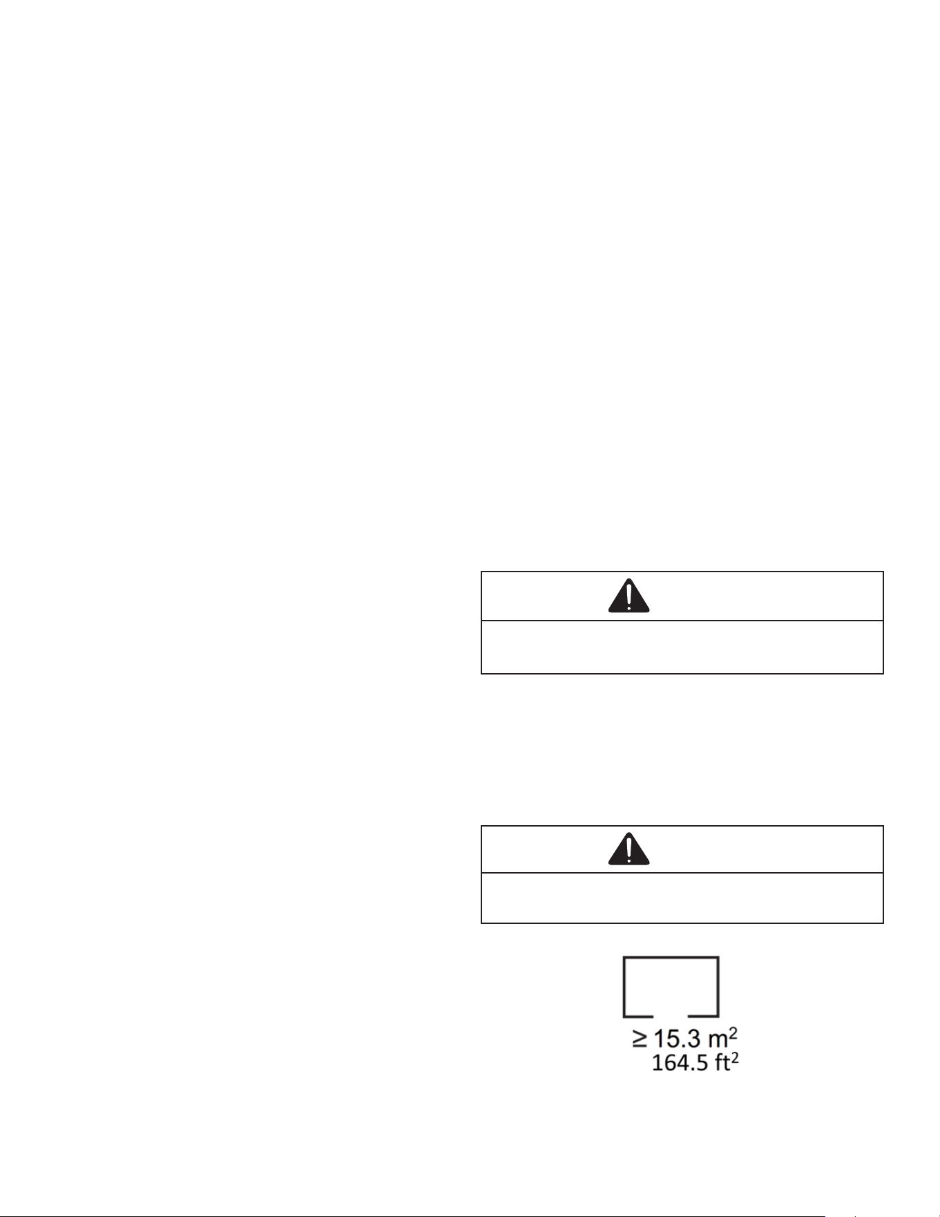
The appliance shall be installed, operated and stored in
room with a floor area not less than the minimum room
area.
Minimum Room Area
IMPORTANT NOTE: Refer to the Altitude Adjusted
room area calculation referenced in this manual.

7
NOTE: Appliance is shipped from factory for
vertical duct application.
All Installations
Proper installation of the unit ensures troublefree
operation. Improper installation can result in problems
ranging from noisy operation to property or equipment
damages, dangerous conditions that could result in injury
or personal property damage and that are not covered by
the warranty. Give this booklet to the user and explain it’s
provisions. The user should retain these instructions for
future reference.
• For proper ame pattern within the heat exchanger
and proper condensate drainage, the unit must be
mounted level.
• The ue outlet must be at least 12 inches from any
opening through which ue gases could enter a
building, and at least three feet above any forced
air inlet located within ten feet. The economizer/
manual fresh air intake/motorized fresh air intake
and combustion air inlet mounted on the unit are not
aected by this restriction.
• To avoid possible corrosion of the heat exchanger,
do not locate the unit in an area where the outdoor
air (i.e. combustion air for the unit) will be frequently
contaminated by compounds containing chlorine
or uorine. Common sources of such compounds
include swimming pool chemicals and chlorine
bleaches, paint stripper, adhesives, paints, varnishes,
sealers, waxes (which are not yet dried) and solvents
used during construction and remodeling. Various
commercial and industrial processes may also be
sources of chlorine/uorine compounds.
• The unit shall not be connected to a chimney ue
serving a separate appliance designed to burn solid
fuel.
• To avoid possible illness or death of the building
occupants, do NOT locate outside air intake device
(economizer, manual fresh air intake, motorized fresh
air intake) too close to an exhaust outlet, gas vent
termination, or plumbing vent outlet. For specic
distances required, consult local codes.
• Allow minimum clearances from the enclosure for
re protection, proper operation, and service access
(see unit clearances). These clearances must be
permanently maintained.
• The combustion air inlet and ue outlet on the unit
must never be obstructed. If used, do not allow the
economizer/manual fresh air damper/ motorized fresh
air damper to become blocked by snow or debris. In
some climates or locations, it may be necessary to
elevate the unit to avoid these problems.
• When the unit is heating, the temperature of the return
air entering the unit must be a minimum of 55° F.
Ground Level Installations Only:
• When the unit is installed on the ground adjacent
to the building, a level concrete (or equal) base is
recommended. Prepare a base that is 3” larger than
the package unit footprint and a minimum of 3” thick.
• The base should also be located where no runo of
water from higher ground can collect in the unit.
Roof top Installations Only:
• To avoid possible property damage or personal injury,
the roof must have sucient structural strength to
carry the weight of the unit(s) and snow or water
loads as required by local codes. Consult a structural
engineer to determine the weight capabilities of the
roof.
• The unit may be installed directly on wood oors or on
Class A, Class B, or Class C roof covering material.
• To avoid possible personal injury, a safe, at surface
for service personnel should be provided.
• As indicated on the unit data plate, a minimum
clearance of 36” to any combustible material is
required on the furnace access side of the unit. All
combustible materials must be kept out of this area.
• This 36” clearance must also be maintained to
insure proper combustion air and ue gas ow. The
combustion air intake and furnace ue discharge must
not be blocked for any reason, including blockage by
snow.
• Adequate clearances from the furnace ue discharge
to any adjacent public walkways, adjacent buildings,
building openings or openable windows must be
maintained in accordance with the latest edition of the
National Fuel Gas Code ANSI Z223.1/NFPA 54.
• Minimum horizontal clearance of 48” from the furnace
ue discharge to any electric meters, gas meters,
regulators and relief equipment is required.
Unit Precautions
• Do not stand or walk on the unit.
• Do not drill holes anywhere in panels or in the base
frame of the unit except where indicated. Unit access
panels provide structural support.
• Do not remove any access panels until unit has been
installed on roof curb or eld supplied structure.
• Do not roll unit across nished roof without prior
approval of owner or architect.
• Do not skid or slide on any surface as this may
damage unit base. The unit must be stored on a at,
level surface. Protect the condenser coil because it is
easily damaged.
Roof Curb Installations Only:
Curb installations must comply with local codes and should
be done in accordance with the established guidelines of
the National Roong Contractors Association.
Proper unit installation requires that the roof curb be rmly
and permanently attached to the roof structure. Check for
adequate fastening method prior to setting the unit on the
curb.
8
Full perimeter roof curbs are available from the factory
and are shipped unassembled. Field assembly, squaring,
leveling and mounting on the roof structure are the
responsibility of the installing contractor. All required
hardware necessary for the assembly of the sheet metal
curb is included in the curb accessory.
• Sucient structural support must be determined prior
to locating and mounting the curb and package unit.
• Ductwork must be constructed using industry
guidelines. The duct work must be placed into the
roof curb before mounting the package unit. Our full
perimeter curbs include duct connection frames to be
assembled with the curb. Cantilevered type curbs are
not available from the factory.
• Curb insulation, cant strips, ashing and general
roong material are furnished by the contractor.
• The curbs must be supported on parallel sides by roof
members.
• The roof members must not penetrate supply and
return duct opening areas as damage to the unit might
occur.
NOTE: The unit and curb accessories are designed
to allow vertical duct installation before unit
placement. Duct installation after unit placement
is not recommended.
CAUTION
All curbs look similar. To avoid incorrect curb positioning,
check job plans carefully and verify markings on curb
assembly. Instructions may vary in curb styles and
supersedes information shown.
See the manual shipped with the roof curb for assembly
and installation instructions.
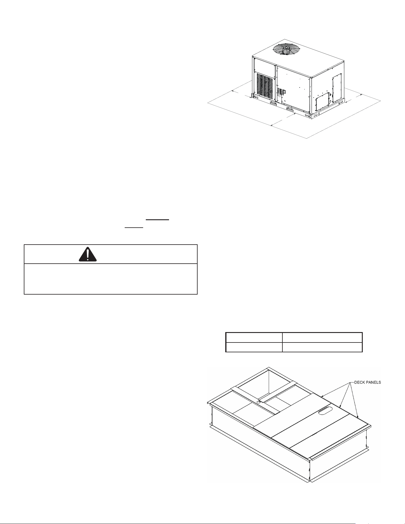
CLEARANCES
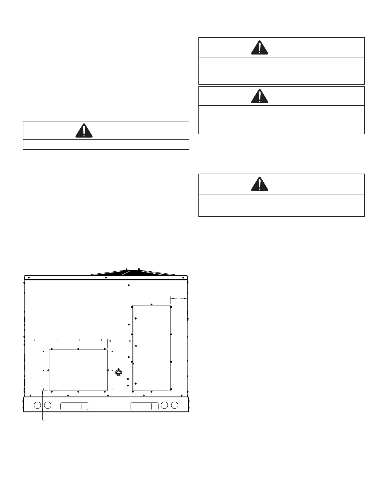
24" MIN.
24" MIN.
36” MIN.
Unit Clearances
*In situations that have multiple units, a 36” minimum
clearance is required between the condenser coils.
Adequate clearance around the unit should be kept for
safety, service, maintenance, and proper unit operation.
A clearance of 48” is recommended on all sides of the
unit to facilitate possible parts replacement, to allow
service access and to insure proper ventilation and
condenser airow. The top of the unit should be completely
unobstructed. If units are to be located under an overhang,
there should be a minimum of 48” clearance and provisions
made to deect the warm discharge air out from the
overhang. The unit should be installed remote from all
building exhausts to inhibit ingestion of exhaust air into the
unit fresh air intake.
NOTE: If the 36” minimum clearance is used on
the control panel side of unit, a flue extension
kit needs be to installed to prevent flue gas
recirculation. See table below for the kit
selection.
Model size Kit part number
5 ton HEFLUE048060RH
Flue Extension Kits
Roof Curb Installation
9
ROOF CURB POST-INSTALLATION CHECKS
After installation, check the top of the curb, duct connection
frame and duct anges to make sure gasket has been
applied properly. Gasket should be rmly applied to the top
of the curb perimeter, duct anges and any exposed duct
connection frame. If gasket is loose, reapply using strong
weather resistant adhesive.
Protrusion
Inspect curb to ensure that none of the utility services
(electric) routed through the curb protrude above the curb.
CAUTION
If protrusions exist, do not attempt to set unit on curb.
ROOF TOP DUCT CONNECTIONS
Install all duct connections on the unit before placing the
unit on rooftop.
Horizontal Discharge
Refer to IOD7019 included in the literature pack for
installing horizontal duct covers.
Flexible duct connectors between the unit and ducts are
recommended. Insulate and weatherproof all external
ductwork and joints as required and in accordance with
local codes.
5
6-3/16
73/8
SUPPLY
12" X 17"
RETURN
11" X 25"
Horizontal Discharge Duct Connections
RIGGING DETAILS
WARNING
To prevent property damage, the unit should remain in an
upright position during all rigging and moving operations. To
facilitate lifting and moving when a crane is used, place the
unit in an adequate cable sling.
CAUTION
If units are lifted two at a time, the fork holes on the
condenser end of the unit must not be used. Minimum fork
length is 42” to prevent damage to the unit; however, 48” is
recommended.
Provisions for forks have been included in the
unit base frame. No other fork locations are
approved.
WARNING
To prevent possible equipment damage, property damage,
personal injury or death, the following bullet points must
be observed when installing the unit.
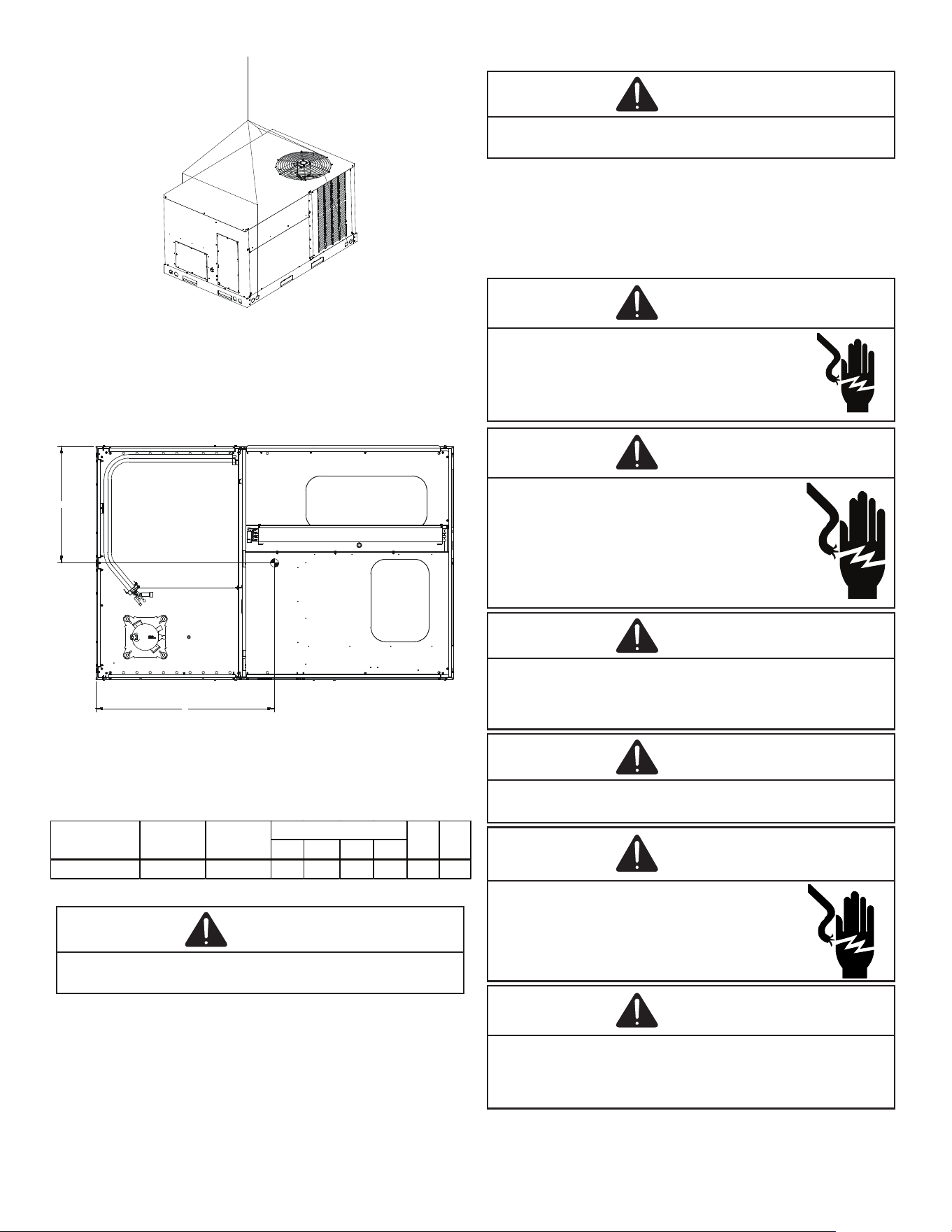
• Unit must be lifted by the four lifting holes located at
the base frame corners.
• Lifting cables should be attached to the unit with
shackles.
• The distance between the crane hook and the top of
the unit must not be less than 60”.
• Two spreader bars must span over the unit to prevent
damage to the cabinet by the lift cables. Spreader
bars must be of sucient length so that cables do
not come in contact with the unit during transport.
Remove wood struts mounted beneath unit base
frame before setting unit on roof curb. These struts
are intended to protect unit base frame from fork lift
damage. Removal is accomplished by extracting the
sheet metal retainers and pulling the struts through
the base of the unit. Refer to rigging label on the unit.
IMPORTANT NOTE: If using bottom discharge
with roof curb, ductwork should be attached to
the curb prior to installing the unit. Ductwork
dimensions are shown in Roof Curb Installation
Instructions.
Refer to the Roof Curb Installation Instructions for proper
curb installation. Curbing must be installed in compliance
with the National Roong Contractors Association Manual.
10
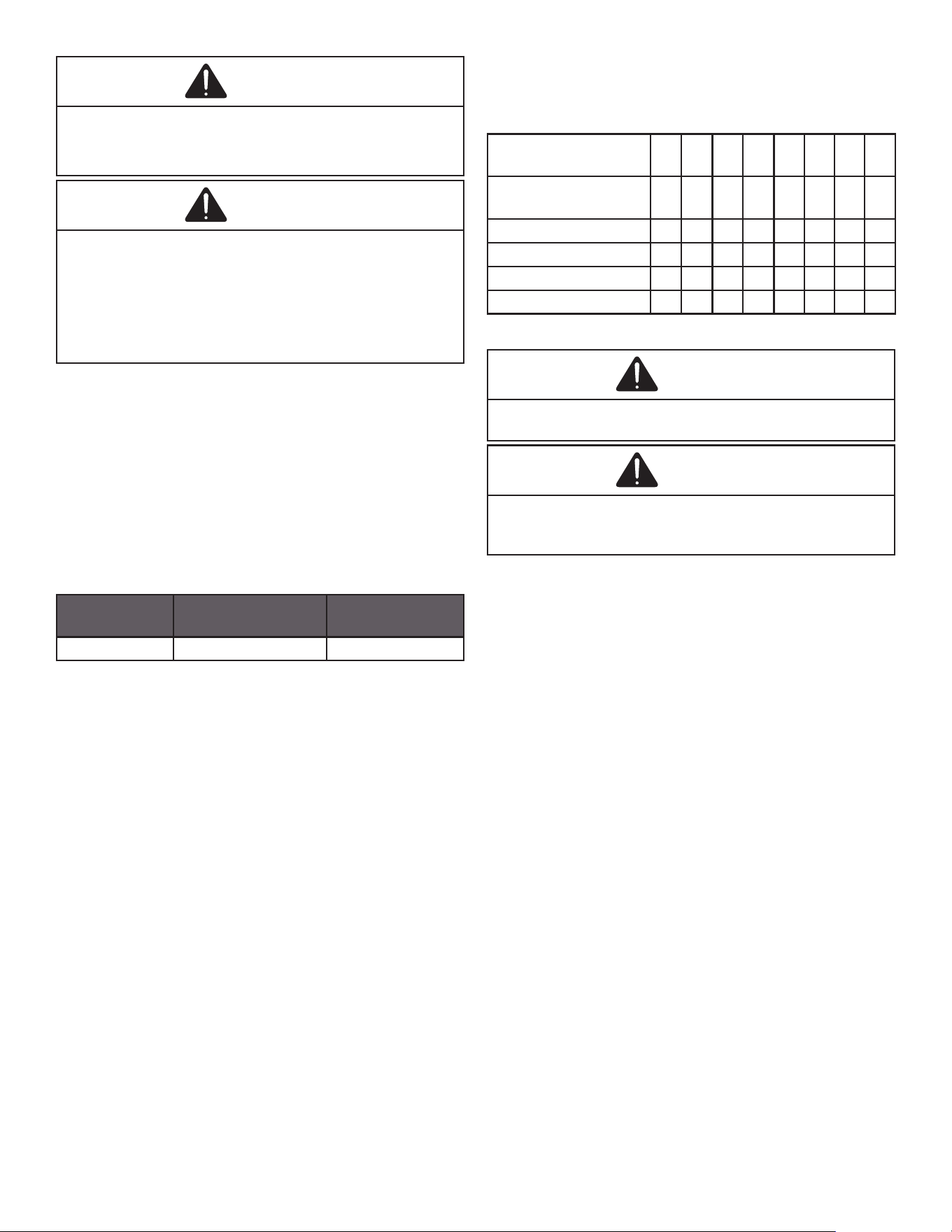
To assist in determining rigging requirements, unit weights
and center of gravity are shown as follows:
WEIGHTS AND CENTER OF GRAVITY
Y
X
CG
COMPRESSOR
CONDENSER COIL
RETURN
EVAPORATOR COIL
B
C
D
A
SUPPLY
Corner and center of gravity locations
NOTE: Unit should be lifted at a point above
center of gravity.
A B C D
GPGM56014031 713 655 148 189 135 183 35.8 27.5
Model X (in) Y (in)
Shipping
Weight (lb)
Operang
Weight (lb)
Corner Weights (lb)
CAUTION
To prevent severe damage to the bottom of the unit, do not
fork lift unit after wood struts have been removed.
Bring condenser end of unit into alignment with the curb
rst. Lower unit carefully onto roof mounting curb. When a
rectangular cantilever curb is used, care should be taken to
center the unit. Check for proper alignment and orientation
of supply and return openings with duct.
Rigging Removal
CAUTION
To prevent damage to the unit, do not allow crane hooks and
spreader bars to rest on the roof of the unit.
Remove spreader bars, lifting cables and other rigging
equipment.
ELECTRICAL WIRING
WARNING
HIGH VOLTAGE!
Disconnect all power before servicing or
installing this unit. Multiple power sources
may be present. Failure to do so may cause
property damage, personal injury or death.
WARNING
HIGH VOLTAGE!
To avoid personal injury or death due to
electrical shock, do not tamper with factory
wiring. The internal power and control
wiring of these units are factory-installed
and have been thoroughly tested prior to
shipment. Contact your local representative if
assistance is required.
CAUTION
To prevent damage to the wiring, protect wiring from sharp
edges. Follow national electrical code and all local codes
and ordinances. Do not route wires through removable
access panels.
CAUTION
Conduit and fittings must be weather-tight to prevent water
entry into the building.
WARNING
HIGH VOLTAGE!
Prior to servicing the unit or removing the
compressor terminal plug or terminal cover,
disconnect all electrical power from the unit.
Multiple power sources may be present.
WARNING
Do not operate the compressor(s) without the terminal plug
fully engaged or the terminal cover properly installed.
Get away if unusual sounds are heard from within the
compressor. Disconnect electrical power from the unit.
11
WARNING
A tripped circuit breaker or blown fuse may indicate that an
electrical problem exists. Do not reset a circuit breaker
or replace fuses without first performing thorough
electrical troubleshooting and testing procedures.
WARNING
Hermetic compressor electrical terminal venting can be
dangerous. In certain circumstances, the terminal may be
expelled, venting the refrigerant vapor and compressor
oil contained within the compressor housing and system. Be
alert for sounds of arcing (sizzling, sputtering, or popping)
inside the compressor. Immediately get away if you hear
these sounds and disconnect electrical power from the
unit.
High Voltage Wiring
For unit protection, use a fuse or HACR circuit breaker that
is in excess of the circuit ampacity, but less than or equal
to the maximum overcurrent protection device. DO NOT
EXCEED THE MAXIMUM OVERCURRENT DEVICE SIZE
SHOWN ON UNIT DATA PLATE.
All line voltage connections must be made through
weatherproof ttings. All exterior power supply and ground
wiring must be in approved weatherproof conduit.
Rated Voltage
Minimum Supply
Voltage
Maximum
Supply Voltage
208/240V 197 253
The main power supply wiring to the unit and low voltage
wiring to accessory controls must be done in accordance
with these instructions, the latest edition of the National
Electrical Code (ANSI/NFPA 70), and all local codes and
ordinances.
Ensure the data plate is NOT covered by the eld installed
disconnect.
The unit is factory wired for the voltage shown on the unit’s
data plate.
NOTE: The unit transformer is factory connected
for 240V operation. If the unit is to operate on
208V, recon nect the transformer primary lead as
shown on the unit wiring diagram.
Main power wiring should be sized for the minimum
circuit ampacity shown on the unit’s database. Size wires
in accordance with the ampacity tables in Article 310 of
the National Electrical Code. If long wires are required,
it may be necessary to increase the wire size to prevent
excessive voltage drop. Wires should be sized for a
maximum of 3% voltage drop.
Connect incoming power leads to terminals L1 & L2 on
con tactor in the electrical control section, using wire sizes
spec ied in wiring table.
Branch Circuit
Ampacity
15 20 25 30 35 40 45 50
SUPPLY WIRE
LENGTH - FEET
200 6 4 4 4 3 3 2 2
150 8 6 6 4 4 4 3 3
100 10 8 8 6 6 6 4 4
50 14 12 10 10 8 8 6 6
Wiring Table
CAUTION
To avoid risk of property damage, personal injury or fire,
use only copper conductors.
CAUTION
To prevent improper and dangerous operation due to
wiring errors, label all wires prior to disconnection when
servicing controls. Verify proper operation after servicing.
NOTE: A weather-tight disconnect switch, properly
sized for the unit total load, must be field or
factory installed. An external field supplied
disconnect may be mounted on the exterior panel.
Ensure the data plate is not covered by the eldsupplied
disconnect switch.
• Some disconnect switches are not fused. Protect the
power leads at the point of distribution in accordance
with the unit data plate.
• The unit must be electrically grounded in accordance
with local codes or, in the absence of local codes,
with the latest edition of the National Electrical Code
ANSI/NFPA 70, and/or the Canadian Electrical Code,
CSA C22.1, Part 1. A ground lug is provided for this
purpose. Do not use the ground lug for connecting a
neutral conductor.
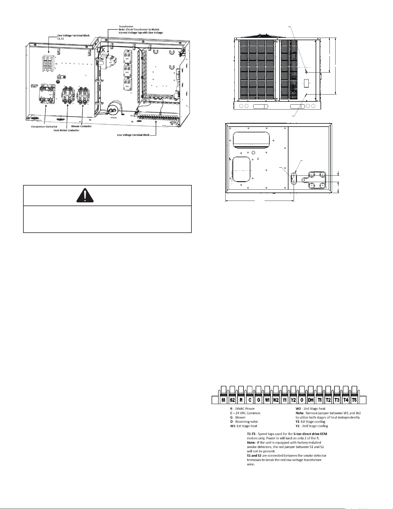
• Connect power wiring to the electrical power block
located within the main control box.
12
Electrical Panel
NOTE: Depending on the options installed, the
location of the components may vary in some
models.
WARNING
Failure of unit due to operation on improper line voltage or
with excessive phase unbalance constitutes product abuse
and is not covered by the warranty, and it may cause severe
damage to the unit electrical components.
Areas Without Convenience Outlet
It is recommended that an independent 115V power source
be brought to the vicinity of the roof top unit for portable
lights and tools used by the service mechanic.
NOTE: Refer to local codes for requirements.
These outlets can also be factory installed.
Units installed on Roof Tops
Main power and low voltage wiring may enter the unit
through the condenser end of unit or through the roof curb.
Install conduit connectors at the desired entrance locations.
External connectors must be weatherproof. All holes in the
unit base must be sealed (including those around conduit
nuts) to prevent water leakage into building. All required
conduit and ttings are to be eld supplied.
Supply voltage to roof top unit must not vary by more than
10% of the value indicated on the unit data plate. Phase
voltage unbalance must not exceed 2%. Contact your local
power company for correction of improper voltage or phase
unbalance.
4-1/2"
47-9/16"
7-1/2"
4-1/16 DIA.
POWER THRU
THE CURB
RETURN
19-3/8
31-3/8
LOW VOLTAG E
ENTRANCE
HIGH VOLTAGE ENTRANCE
(REMOVE PLUG)
Electrical Entrance and thru Curb
(Bottom View of Unit)
Low Voltage Control Wiring
1. A 24V thermostat must be installed for unit operation.
2. Locate thermostat or remote sensor in the conditioned
space where it will sense average temperature. Do
not locate the device where it may be directly exposed
to supply air, sunlight or other sources of heat. Follow
installation instructions packaged with the thermostat.
3. Use #18 AWG wire for 24V control wiring runs not
exceeding 75 feet. Use #16 AWG wire for 24V control
wiring runs not exceeding 125 feet. Use #14 AWG
wire for 24V control wiring runs not exceeding 200
feet. Low voltage wiring may be National Electrical
Code (NEC) Class 2 where permitted by local codes.
4. Route thermostat wires from subbase terminals
to the unit. Control wiring should enter through the
condenser panel opening or through curb indicated in
“Electrical Entrance” gure. Connect thermostat and
any accessory wiring to low voltage terminal block
TB1 in the main control box.
13
NOTE:Field-supplied conduit may need to be
installed depending on unit/curb configuration.
Use #18 AWG solid conductor wire whenever
connecting thermostat wires to terminals on
sub-base. DO NOT use larger than #18 AWG wire. A
transition to #18 AWG wire may be required before
entering thermostat sub-base.
NOTE: Refer to unit wiring diagrams for
thermostat or remote sensor connections.
GAS SUPPLY PIPING
WARNING
To prevent personal injury or death due to improper
installation, adjustment, alteration, service or maintenance,
refer to this manual. For additional assistance or
information, consult a qualified installer, servicer agency
or the gas supplier.
IMPORTANT NOTE: This unit is factory set to
operate on natural gas at the altitudes shown on
the rating plate.
WARNING
To avoid property damage, personal injury or death when
either using propane gas alone or at higher altitudes, obtain
and install the proper conversion kit(s). Failure to do so can
result in unsatisfactory operation and/or equipment damage.
High altitude kits are for U.S. installations only and are not
approved for use in Canada.
The rating plate is stamped with the model number, type of
gas and gas input rating. Make sure the unit is equipped
to operate on the type of gas available. Conversion to
propane (LP) gas is permitted with the use of the factory
authorized conversion kit (see the unit Technical Manual for
the appropriate kit). For High Altitude derates, refer to the
latest edition of the National Fuel Gas Code NFPA 54/ANSI
Z223.1 or National Standard of Canada, Natural Gas and
Propane Installation Code, CSA B149.1.
The minimum supply pressure should not vary from that
shown in the table above because this could prevent the
unit from having dependable ignition. In addition, gas input
to the burners must not exceed the rated input shown
on the rating plate. Overring of the unit could result in
premature heat exchanger failure.
Piping
IMPORTANT NOTE: To avoid possible unsatisfactory
operation or equipment damage due to under
firing of equipment, do not undersize the natural/
propane gas piping from the meter/tank to the unit.
When sizing a trunk line, include all appliances on
that line that could be operated simultaneously.
The gas line installation must comply with local codes, or
in the absence of local codes, with the latest edition of the
National Fuel Gas Code NFPA 54 / ANSI Z223.1.
Natural Gas Connection
1/2
3/4
1
1 1/4
1 1 /2
10
132
278
520
1050
1600
20
92
190
350
730
1100
30
73
152
285
590
980
40
63
130
245
500
760
50
56
115
215
440
670
60
50
105
195
400
610
70
46
96
180
370
560
80
43
90
170
350
530
90
40
84
160
320
490
100
38
79
150
305
460
Pressure= .50 PSIG or less and Pressure Drop of 0.3" W.C.
(Based on 0.60 Specific Gravity Gas)
Natural Gas Capacity of Pipe
in Cubic Feet of Gas Per Hour (CFH)
Nominal Black Pipe Size (inches)
Length of
Pipe in Feet
Heating Value of Gas (BTU/Cubic Foot
CFH =
BTUH Furnace Input
Refer to the Proper Piping Practice drawing for the general
layout at the unit. The following rules apply:
1. Use black iron pipe and ttings for the supply piping.
The use of a ex connector and/or copper piping is
permitted as long as it is in agreement with local
codes.
2. Use pipe joint compound on male threads only. Pipe
joint compound must be resistant to the action of the
fuel used.
3. Use ground joint unions.
4. Install a drip leg to trap dirt and moisture before it can
enter the gas valve. The drip leg must be a minimum
of three inches long.
5. Use two pipe wrenches when making connection to
the gas valve to keep it from turning.
6. Install a manual shuto valve in a convenient location
(within six feet of unit) between the meter and the unit.
7. Tighten all joints securely.
8. The unit must be connected to the building piping by
one of the following methods:
• Rigid metallic pipe and ttings.
• Semirigid metallic tubing and metallic ttings
(Aluminum alloy tubing must not be used in
exterior locations).
• Listed gas appliance connectors used in
accordance with the terms of their listing
that are completely in the same room as the
equipment. Always use a new listed connector.
• In the prior two methods above the connector
or tubing must be protected from physical
and thermal damage. Aluminum alloy tubing
and connectors must be coated to protect
against external corrosion when in contact with
masonry, plaster or insulation or are subject to
repeated wettings by liquids (water not rain
water, detergents or sewage).
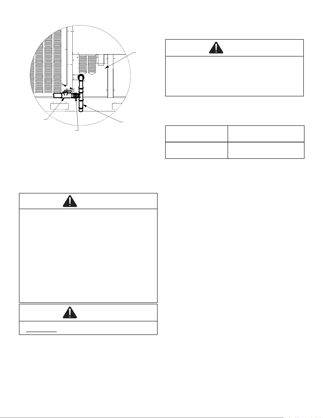
14
BURNER
DOOR
DRIP
LEG
MANUAL
SHUT-OFF
GROUND JOINT
UNION
TBD
Proper piping practice
NOTE: The unit gas supply entrance is factory
sealed with plugs. Keep plugs in place until
gas supply is ready to be installed. Once ready,
replace the plugs with the supplied grommets and
install gas supply line.
Gas Piping Checks
CAUTION
To prevent property damage or personal injury due to fire,
the following instructions must be preformed regarding
gas connections and pressure testing:
• The unit and its gas connections must be leak tested
before placing in operation. Because of the danger of
explosion or fire, never use a match or open flame to
test for leaks. Never exceed specified pressures for
testing. Higher pressure may damage gas valve and
cause overfiring which may result in premature heat
exchange failure.
• This unit and its shut-off valve must be disconnected
from the gas supply during any pressure testing of
that system at test pressures in excess of ½ PSIG (3.48
kPa).
• This unit must be isolated from the gas supply system
by closing its manual shut-off valve during any
pressure testing of the gas supply piping system at test
pressures equal to or less than ½ PSIG (3.48 kPa).
WARNING
To avoid property damage or personal injury, be sure there
is no open flame in the vicinity during air bleeding.
There will be air in the gas supply line after testing for leaks
on a new installation. Therefore, the air must be bled from
the line by loosening the ground joint union until pure gas
is expelled. Tighten union and wait for ve minutes until all
gas has been dissipated in the air. Be certain there is no
open ame in the vicinity during air bleeding procedure.
The unit is placed in operation by closing the main
electrical disconnect switch for the unit.
PROPANE GAS INSTALLATIONS
WARNING
To avoid property damage, personal injury or death due to
fire or explosion caused by a propane gas leak, install a gas
detecting warning device. Since rust can reduce the level
of odorant in propane gas, a gas detecting warning device is
the only reliable way to detect a propane gas leak. Contact a
local propane gas supplier about installing a gas detecting
warning device.
IMPORTANT NOTE: Propane gas conversion kits
must be installed to convert units to propane gas.
LP CONVERSION
KIT
MODEL
LPM08
TWOSTAGE HEATING
MODELS
All propane gas equipment must conform to the safety
standards of NFPA 58 Liqueed Petroleum Gas Code.
For satisfactory operation, propane gas pressure must be
within 9.7 10.3 inches w.c. for high re at the manifold
with all gas appliances in operation. Maintaining proper
gas pressure depends on three main factors:
1. Vaporization rate, which depends on (a) temperature
of the liquid, and (b) wetted surface area of the
container or containers.
2. Proper pressure regulation.
3. Pressure drop in lines between regulators, and
between second stage regulator and the appliance.
Pipe size required will depend on length of pipe run
and total load of all appliances.
Tanks and Piping
Complete information regarding tank sizing for
vaporization, recommended regulator settings and pipe
sizing is available from most regulator manufacturers and
propane gas suppliers.
Since propane gas will quickly dissolve white lead or most
standard residential compounds, special pipe dope must
be used. Shellac base compounds resistant to the actions
of liqueed petroleum gases such as Gasolac
®
, Stalactic
®
,
Clyde’s
®
or John Crane
®
are satisfactory.
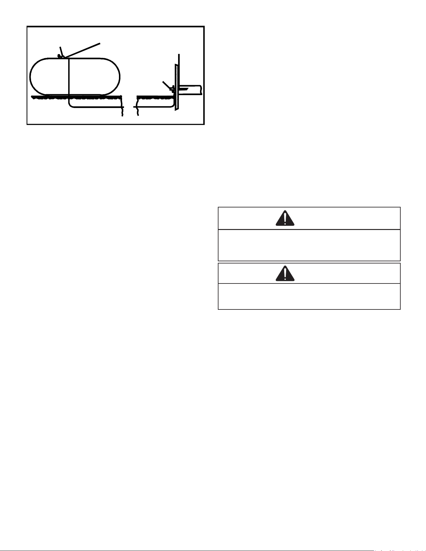
See the following gure for typical propane gas piping.
15
200 PSIG
Maximum
5 to 15 PSIG
(20 PSIG Max.)
Continuous
11" W.C.
Second Stage
Regulator
First Stage
Regulator
Typical propane gas piping
Roof Top Location and Installation
The gas supply piping location and installation for roof top
units must be in accordance with local codes or, in the
absence of locals codes, with ordinances of the latest edition
of the National Fuel Gas Code ANSI Z223.1/NFPA 54.
A manual gas shut o valve must be eld installed external
to the roof top unit. In addition, a drip leg must be installed
near the inlet connection. A ground joint union connection
is required between the external shut o valve and the unit
connection to the gas valve to permit removal of the burner
assembly for servicing.
1. Route gas piping to unit so that it does not interfere
with the removal of access panels. Support and
align piping to prevent strains or misalignment of the
manifold assembly.
2. All units are furnished with standard female 1/2” NPT
pipe connections. The size of the gas supply piping
to the unit must be based on length of run, number
of units on the system, gas characteristics, BTU
requirement and available supply pressure. All piping
must be done in accordance with local codes or, in the
absence of local codes, with the latest edition of the
National Fuel Gas Code ANSI Z223.1/NFPA 54.
NOTE: The gas connection size at the unit does
NOT establish the size of the supply line.
3. These units are designed for either natural or
propane (LP) gas and are specically constructed at
the factory for only one of these fuels. The fuels are
NOT interchangeable. However, the furnace can be
converted in the eld from natural gas to LP gas with
the appropriate factory kit (see unit Technical Manual
for the appropriate kit). Only a qualied contractor,
experienced with natural and propane gas systems,
should attempt conversion. Kit instructions must
be followed closely to assure safe and reliable unit
operation.
4. With all units on a common line operating under
full re, natural gas main supply pressure should
be adjusted to approximately 7.0” w.c., measured
at the unit gas valve. If the gas pressure at the
unit is greater than 10.0” w.c., the contractor must
furnish and install an external type positive shut o
service pressure regulator. The unit will not function
satisfactorily if supply gas pressure is less than 5.0”
w.c. or greater than 10.0” w.c..
NOTE: A minimum horizontal distance of 48”
between the regulator and the furnace flue
discharge is required.
5. With all units on a common line operating under
full LP gas main supply pressure should be at least
11.0” w.c. and must be no greater than 13.0” w.c.,
measured at the unit gas valve. Unit will not function
satisfactorily if supply gas pressure is less than 11.0”
w.c. or greater than 13.0” w.c..
6. All pipe connections should be sealed with a pipe
thread compound, which is resistant to the fuel used
with the furnace. A soapy water solution should be
used to check all joints for leaks. A tap is located
on the entering side of the gas valve for test gauge
connection to measure supply (main) gas pressure.
Another tap is provided on the manifold side of the
gas valve for checking manifold pressure.
WARNING
This unit and its individual shutoff valve must be
DISCONNECTED from the gas supply system during any
pressure testing of that system at test pressures in excess
of ½ PSIG (13.8” w.c.).
CAUTION
This unit must be ISOLATED from the gas supply piping system
by closing its individual manual shutoff valve during any
pressure testing equal to or less than ½ PSIG.
7. There must be no obstruction to prevent the ow of
combustion and ventilating air. A vent stack is not
required and must never be used. The induced draft
fan will supply an adequate amount of combustion
air as long as the air passageways are kept free of
any obstructions and the recommended external unit
clearances are maintained.
CIRCULATING AIR AND FILTERS
Ductwork
The supply duct from the unit through a wall may be
installed without clearance. However, minimum unit
clearances must be maintained (see “Clearances” section).
The supply duct should be provided with an access panel
large enough to inspect the air chamber downstream of
the heat exchanger. A cover should be tightly attached to
prevent air leaks. False ceilings or drop ceilings may be
used as a return air plenum.
NOTE: Adequate return grills have to be supplied
for each room for proper return for that space.
16
Ductwork dimensions are shown in the roof curb
installation manual.
If desired, supply and return duct connections to the unit
may be made with exible connections to reduce possible
unit operating sound transmission.
CONDENSATE DRAIN CONNECTION
Condensate Drain Connection
A 3/4” female NPT drain connection is supplied on the
end of the unit and bottom of the drain pan for condensate
piping. An external trap must be installed for proper
condensate drainage. Hand tighten drain tting to the drain
connection.
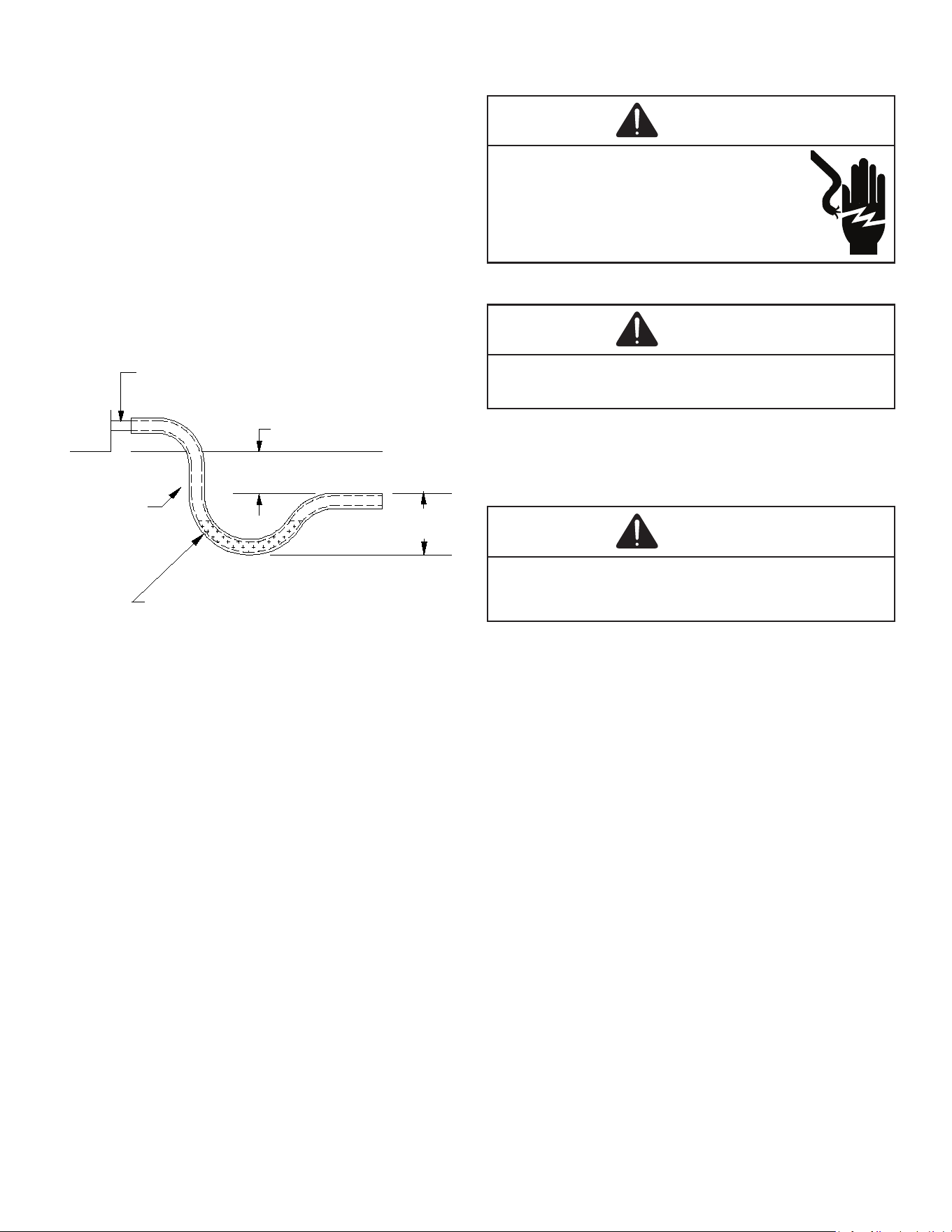
DRAIN
CONNECTION
UNIT 2" MINIMUM
FLEXIBLE
TUBINGHOSE
OR PIPE
3" MINIMUM
A POSITIVE LIQUID
SEAL IS REQUIRED
Drain Connection
Install condensate drain trap as shown. Use 3/4” drain line
and ttings or larger. Do not operate without trap.
Horizontal Drain
Drainage of condensate directly onto the roof may be
acceptable; refer to local code. It is recommended that a
small drip pad of either stone, mortar, wood or metal be
provided to prevent any possible damage to the roof.
Vertical Drain
To use the bottom drain connection, remove the drain plug
from the bottom connection and install it in the horizontal
connection.
Cleaning
Due to the fact that drain pans in any air conditioning
unit will have some moisture in them, algae and fungus
will grow due to airborne bacteria and spores. Periodic
cleaning is necessary to prevent this buildup from plugging
the drain.
STARTUP, ADJUSTMENTS, AND CHECKS
WARNING
HIGH VOLTAGE!
To avoid personal injury or death due to
electrical shock, bond the frame of this unit
to the building electrical ground by use of
the grounding terminal provided or other
acceptable means. Disconnect all power
before servicing or installing this unit.
Pre-Startup Instructions - General
CAUTION
To prevent property damage or personal injury, do not
start the unit until all necessary pre-checks and tests have
been performed.
Prior to the beginning of Startup, Adjustments, and Checks
procedures, the following steps should be completed in the
building.
WARNING
MOVING MACHINERY HAZARD!
To prevent possible personal injury or death, disconnect
power to the unit and padlock in the “OFF” position before
servicing fans.
This unit is equipped with an electronic ignition device to
automatically light the main burners. It also has a power
vent blower to exhaust combustion products.
On new installations, or if a major component has been
replaced, the operation of the unit must be checked.
Check unit operation as outlined in the following
instructions. If any sparking, odors, or unusual sounds
are encountered, shut o electrical power and recheck for
wiring errors, or obstructions in or near the blower motors.
Duct covers must be removed before operating unit.
The Startup, Adjustments, and Checks procedure provides
a stepbystep sequence which, if followed, will assure the
proper startup of the equipment in the minimum amount of
time. Air balancing of duct system is not considered part
of this procedure. However, it is an important phase of any
air conditioning system startup and should be performed
upon completion of the Startup, Adjustments, and Checks
procedure. The Startup, Adjustments, and Checks
procedure at outside ambients below 55°F should be
limited to a readiness check of the refrigeration system with
the required nal check and calibration left to be completed
when the outside ambient rises above 55°F.

17
Temporary Heating Or Cooling
If the unit is to be used for temporary heating or cooling, a
“Startup, Adjustments, and Checks” must rst be performed
in accordance with this manual. Damage or repairs due to
failure to comply with these requirements are not covered
under the warranty. After the machines are used for
temporary heating or cooling, inspect the coils, fans, and
motors for unacceptable levels of construction dust and dirt
and install new lters.
Contractor Responsibility
The installing contractor must be certain that:
• All supply and return air ductwork is in place, properly
sealed, and corresponds with installation instructions.
• All thermostats are mounted and wired in accordance
with installation instructions.
• All electric power, all gas, hot water or steam line
connections, and the condensate drain installation
have been made to each unit on the job. These
main supply lines must be functional and capable of
operating all units simultaneously.
• Requirements are met for venting and combustion air.
• Air lters are in place.
• Input rate and temperature rise are adjusted per rating
plate.
Roof Curb Installation Check
Inspect the roof curb for correct installation. The unit and
curb assembly should be level. Inspect the ashing of the
roof mounting curb to the roof, especially at the corners, for
good workmanship. Also check for leaks around gaskets.
Note any deciencies in a separate report and forward to
the contractor.
Obstructions, Fan Clearance and Wiring
Remove any extraneous construction and shipping
materials that may be found during this procedure. Rotate
all fans manually to check for proper clearances and that
they rotate freely. Check for bolts and screws that may
have jarred loose during shipment to the job site. Re
tighten if necessary. Retighten all electrical connections.
Field Duct Connections
Verify that all duct connections are tight and that there is no
air bypass between supply and return.
Pre-startup Precautions
It is important to your safety that the unit has been properly
grounded during installation. Check ground lug connection
in main control box for tightness prior to closing circuit
breaker or disconnect switch. Verify that supply voltage
on line side of disconnect agrees with voltage on unit
identication plate and is within the utilization voltage
range as indicated in Appendix B Electrical Data.
System Voltage - That nominal voltage value assigned
to a circuit or system for the purpose of designating its
voltage class.
Nameplate Voltage - That voltage assigned to a piece of
equipment for the purpose of designating its voltage class
and for the purpose of dening the minimum and maximum
voltage at which the equipment will operate.
Utilization Voltage - The voltage of the line terminals
of the equipment at which the equipment must give fully
satisfactory performance. Once it is established that supply
voltage will be maintained within the utilization range under
all system conditions, check and calculate if an unbalanced
condition exists between phases. Calculate percent voltage
unbalance as follows.
AIR FLOW ADJUSTMENTS
When the nal adjustments are complete, the current
draw of the motor should be checked and compared to
the full load current rating of the motor. The amperage
must not exceed the service factor stamped on the motor
nameplate. The total airow must not be less than that
required for operation of the furnace.
If an economizer is installed, check the unit operating
balance with the economizer at full outside air and at
minimum outside air.
NOTE: Never run high stage CFM below 300
CFM per ton evaporator freezing or poor unit
performance is possible.
ECM - Standard Static Drive Motor
Adjust the CFM for the unit by changing the position of
the low voltage leads on the terminal block TB1. Refer to
Appendix A for blower performance at each speed tap.
Refer to Appendix D for maximum and minimum allowed
airow for heating and cooling.
NOTE: If more than one lead is energized
simultaneously, the motor will run at the higher
speed.
Fan speed for G (Fan), is xed setting on TB1/T1 and
cannot be moved.
Fan speed for Y1 (Low Cool) is xed setting on TB1/T2 and
cannot be moved.
Brown wire W2 (High Heat) is connected to TB1/T3. This
wire can be moved and placed on unoccupied terminal T5.
Purple wire Y2 (High Cool) is connected to TB1/T4. This
wire can be moved and placed on unoccupied terminal T5.
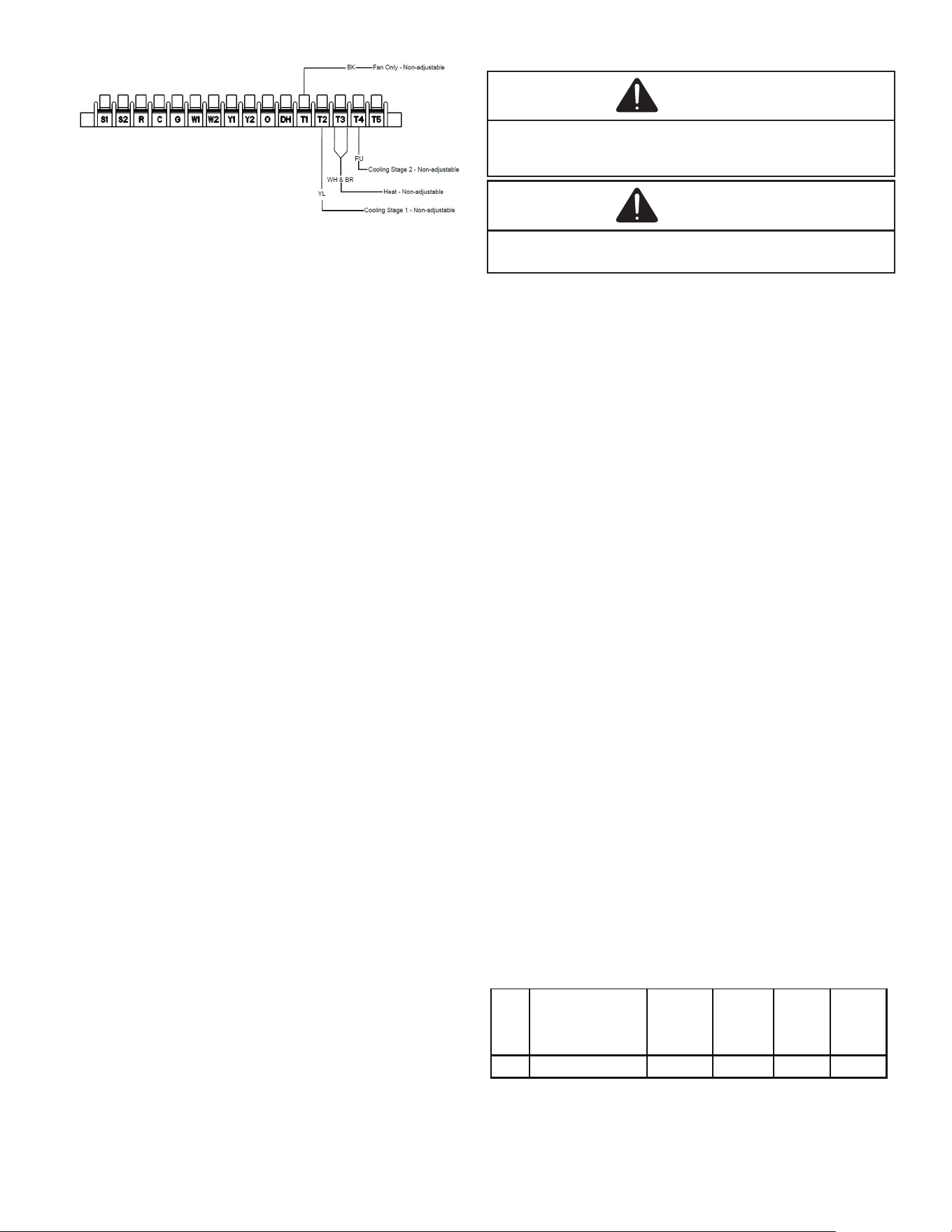
18
Wiring Example
NOTE: For proper operation Y2 and W2 should
have a higher speed setting than the G, Y1 and W1
speed setting.
For gas heat units, the airow must be adjusted so that the
air temperature rise falls within the ranges given stated on
Data Plate.
Electrical Input Check
Make preliminary check of evaporator fan ampere draw
and verify that motor nameplate amps are not exceeded. A
nal check of amp draw should be made upon completion
of air balancing of the duct system (see Appendix B).
GAS SYSTEM CHECK
Pre-Operation Checks
1. Close the manual gas valve external to the unit.
2. Turn o the electrical power supply to the unit.
3. Change heating setpoint to its lowest possible setting.
4. Remove the heat exchanger door on the side of the
unit by removing screws.
5. This unit is equipped with an ignition device which
automatically lights the main burner. DO NOT try to
light burner by any other method.
6. Move the gas control valve switch to the OFF position.
7. Wait ve minutes to clear out any gas.
8. Smell for gas, including near the ground. This is
important because some types of gas are heavier
than air. If you have waited ve minutes and you do
smell gas, immediately follow the warning WHAT TO
DO IF YOU SMELL GAS on page 2 of this manual.
If having waited for ve minutes and no gas smell is
noted, move the gas control valve switch to the ON
position.
9. Replace the heat exchanger door on the side of the
unit.
10. Open the manual gas valve external to the unit.
11. Turn on the electrical power supply to the unit.
12. Change heating setpoint to desired setting.
Gas Supply Pressures & Regulator Adjustments
WARNING
Should overheating occur or the gas supply fail to shut off,
turn off the manual gas shutoff valve external to the unit
before turning off the electrical supply.
WARNING
To avoid property damage, personal injury or death, do not
fire gas unit with flue box cover removed.
NOTE: Except during brief periods when gas
pressures are being measured by qualified
service personnel, the furnace access panel must
always be secured in place when the furnace is in
operation. An inspection port in the access panel is
provided to monitor the flame.
The rst step in checking out the gasred furnace is to test
the gas supply piping to the unit for tightness and purge the
system of air using methods outlined in the latest edition of
the National Fuel Gas Code ANSI Z223.1 / NFPA 54. Verify
that the disconnect switch is in the “OFF” position. A soapy
water solution should be used to check for gas leaks.
Since the unit is subject to considerable jarring during
shipment, it is extremely important that all gas connections
and joints be tested for tightness. Gas piping downstream
from the unit inlet should be checked for leaks during the
subsequent sequence check.
The supply gas pressure should be adjusted to 7.0” w.c.
on natural gas and 11” to 13.0” w.c. on LP gas with the
gas burners operating. If there is more than one unit on
a common gas line, the pressures should be checked
with all units under full re. A supply pressure tap is
provided on the upstream side of the gas valve. A manifold
pressure tap is provided on the manifold side of the gas
valve. The normal manifold pressure for High re is 3.5”
w.c. on natural gas and 10.0” w.c. for propane gas. Low
re natural gas 2.0” w.c., 6.0” w.c. low re propane gas.
Minimum gas supply pressure is 5.0” w.c. for natural gas
and 11.0” w.c. for propane gas.
Do not attempt adjustment of the builtin pressure regulator
unless the supply pressure is at least 5.0” w.c. on natural
gas or 11.0” w.c. on propane gas.
5 GPGM56014031 135,000 6 43 55
Ton Model
L.P.
Orifice
Drill #
High Fire
Rate
BTU/HR
Number
of
Burners
N.G.
Orifice
Drill #
Heat Exchanger and Burner Orifice Specifications
19
NOTE: Gas appliances located more than 2000
feet above sea level must be derated 4% per 1000
feet of total elevation and that variance in gas
heating value and specific gravity require change in
manifold pressure to obtain rating, it is mandatory
that the input be adjusted at the installation site.
All installations should be made as outlined in the
latest edition of the National Fuel Gas Code ANSI
Z223.1, section “Procedures To Be Followed To
Place An Appliance in Operation”. Refer also to the
“User’s Information Manual” supplied with the unit
for additional information on the gas furnace.
Gas Supply And Manifold Check
Gas supply pressure and manifold pressure with the
burners operating must be as specied on the rating plate.
Adjust input rate by varying the adjustment of the gas
pressure regulator on the gas valve. All adjustments
must be made with furnace operating at high re and at
normal operating temperature. A manometer should be
connected to the gas valve to verify pressure is within
the specied range (see following gures for manometer
connections). Clockwise rotation of the pressure regulator
screw increases pressure and gas ow rate. Turn screw
counterclockwise to decrease pressure and gas ow rate.
After adjustment the furnace temperature rise must be
within the range specied on the unit data plate.
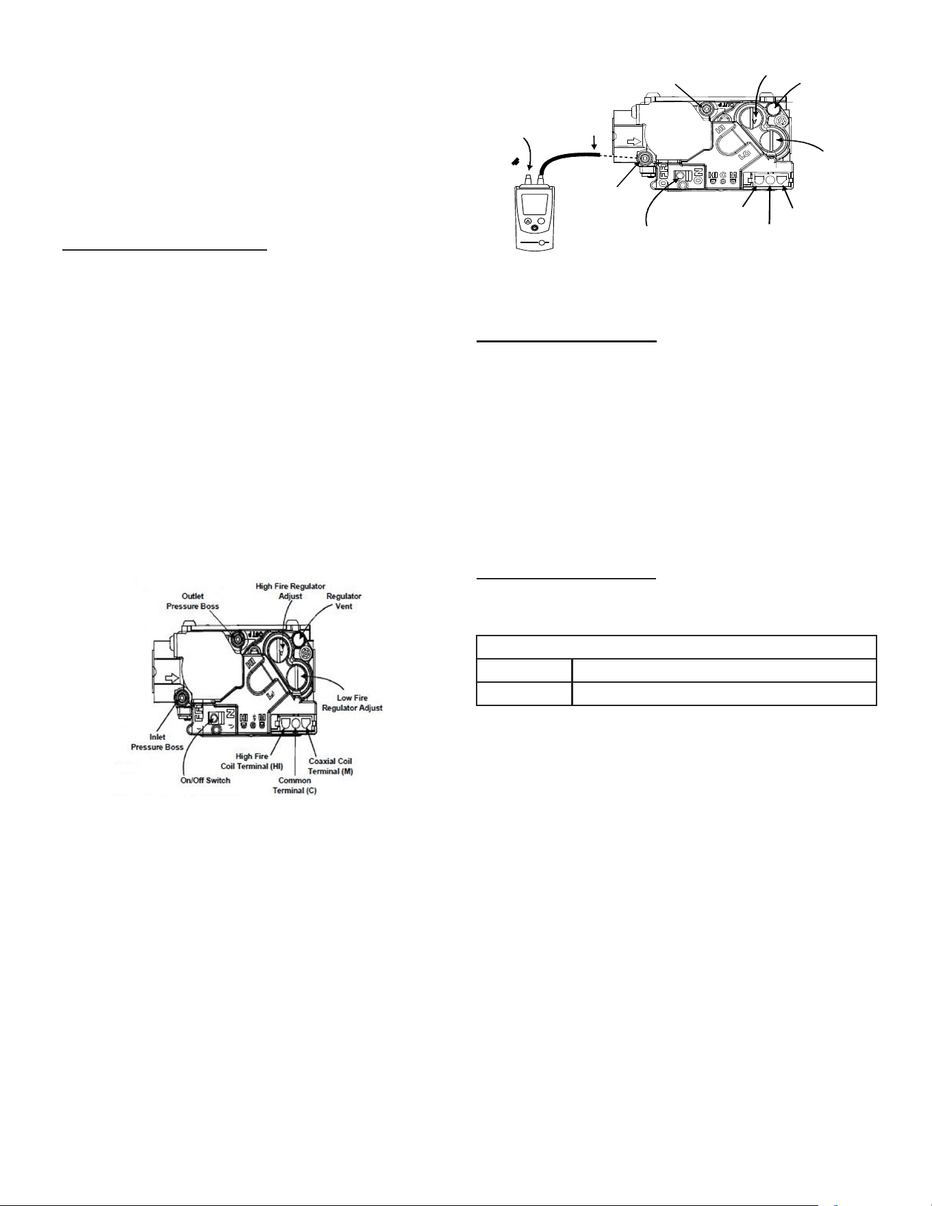
White-Rodgers Model 36G54 (Two Stage)
Gas Inlet Pressure Check
Gas inlet pressure must be checked and adjusted in
accordance to the type of fuel being consumed.
Inlet
Pressure
Boss
Low Fire
Regulator
Adjust
M
a
n
o
m
e
t
e
r
Manometer
H
o
s
e
High Fire Regulator
Adjust
Regulator
Vent
Outlet
Pressure Boss
Open to
Atmosphere
O
n
/
O
f
f
S
w
i
t
c
h
H
i
g
h
F
i
r
e
C
o
i
l
T
e
r
m
i
n
a
l
(
H
I
)
C
o
a
x
i
a
l
C
o
i
l
T
e
r
m
i
n
a
l
(
M
)
Common
Terminal(C)
White-Rodgers Model 36G54 Connected to Manometer
Mode
10.0
White-Rodgers Model 36G54 connected to
Manometer
With Power And Gas O:
1. Back inlet pressure test screw (inlet pressure boss)
out one turn (counterclockwise, not more than
one turn). Alternately, inlet gas pressure may be
measured by removing the cap from the dripleg and
installing a predrilled cap with a hose barb tting.
NOTE: Use adapter kit #0151K00000S to
measure gas pressure on White-Rodgers
36G54 gas valves.
2. Connect a water manometer or adequate gauge to
the inlet pressure tap of the gas valve (or hose barb
tting on predrilled cap).
With Power And Gas On:
3. Put unit into heating cycle and turn on all other gas
consuming appliances.
INLET GAS PRESSURE
Natural Min 5.0” W.C., Max 10.0” W.C.
Propane Min 11.0” W.C., Max 13.0” W.C.
NOTE: Inlet gas pressure must be within the
minimum and maximum value shown in the inlet gas
Pressure chart.
If operating pressures dier from above, make necessary
pressure regulator adjustments, check piping size, etc.,
and/or consult with local utility.
4. Turn o all electrical power and gas supply to the
system.
5. Remove manometer hose from the inlet pressure
boss (or remove hose from hose barb).
6. Turn inlet pressure test screw in to seal pressure port
(clockwise, 7 inlb minimum). Alternately, remove
predrilled cap from dripleg. Reinstall original cap,
sealing with pipe thread compound.
7. Turn on electrical power and gas supply to the
system.
8. Turn on system power and energize valve.
9. Using a leak detection solution or soap suds, check
for leaks at the pressure boss screw (or dripleg cap).
Bubbles forming indicate a leak. SHUT OFF GAS
AND FIX ALL LEAKS IMMEDIATELY.
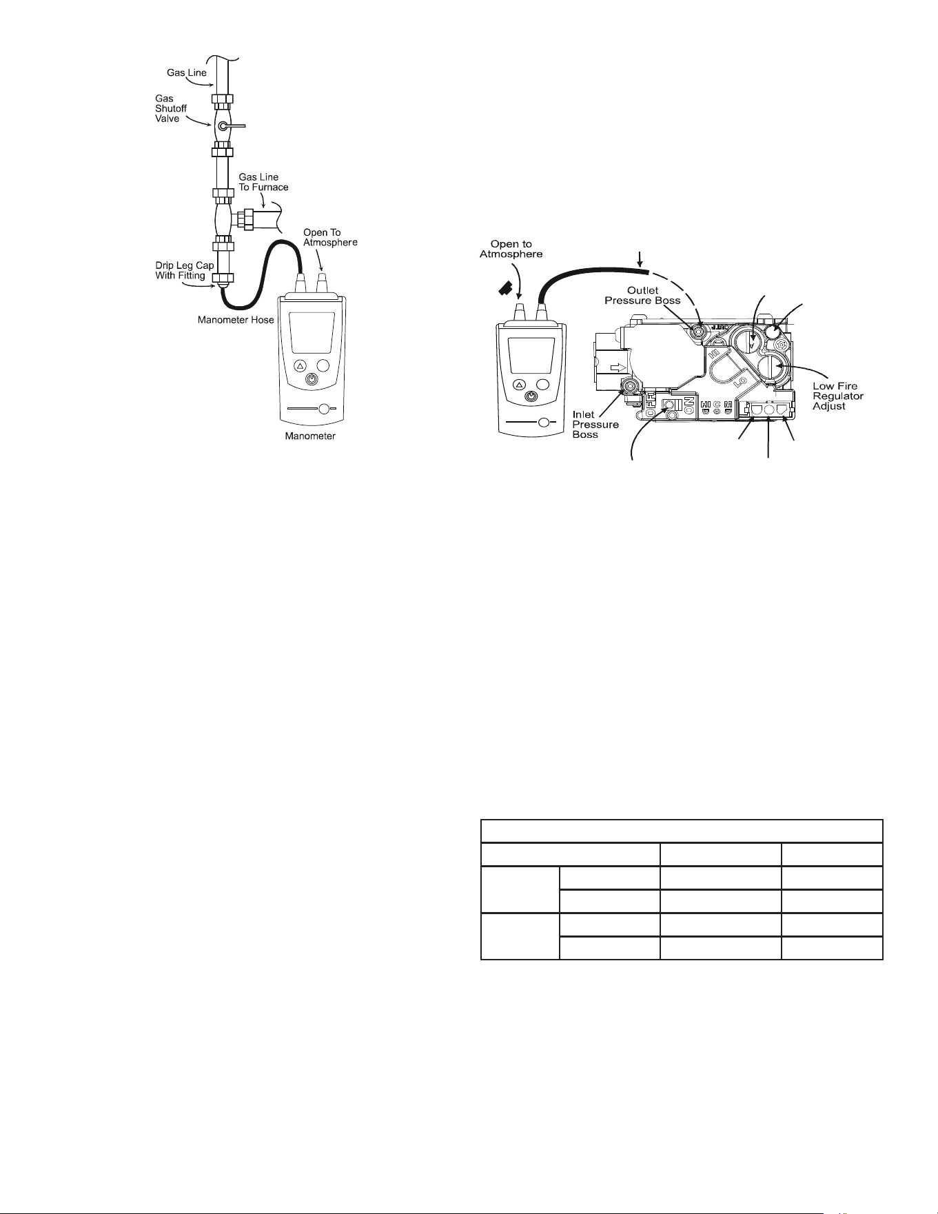
20
Mode
10.0
Measuring Inlet Gas Pressure - Alternate Method
If operating pressures dier from above, make necessary
pressure regulator adjustments, check piping size, etc.,
and/or consult with local utility.
Manifold Pressure Check and Adjustment
The gas valve has a pressure tap to facilitate measurement
of the manifold pressure. The manifold pressure must be
measured with the burners operating.
1. With disconnect switch open, remove eld connected
thermostat wire from terminal R, W1 and W2 on TB1.
Place jumper wire between R, W1 and W2 to engage
high stage heat.
2. See Figure in gas input check section for gas valve
adjustment.
To adjust the pressure regulator, remove the adjustment
screw cover on the gas valve. Turn the adjustment screw
out (counterclockwise) to decrease pressure, turn in
(clockwise) to increase pressure. Only small variations
in gas ow should be made by means of the pressure
regulator adjustment. Any major changes in ow should
be made by changing the size of the burner orices. The
measured input rate to the furnace must not exceed the
rating specied on the unit rating plate.
For natural gas, the high stage manifold pressure must be
between 3.2 and 3.8 inches water column (3.5 nom inal).
Low stage manifold pressure must be between 1.7 to 2.3
inches water column (2.0 nominal).
3. To set low re rate, open disconnect switch and
remove jumper from R to W2. To set low re manifold
pressure, repeat steps above. Refer to Figure in gas
input check section for location of high and low stage
pressure adjustment.
For propane gas, the manifold pressure must be between
9.7 and 10.3 inches water column (10.0 nominal). Low
stage manifold must be between 5.7 and 6.3 inches water
column (6.0 nominal).
NOTE: Thermal efficiency of the furnace is a
product efficiency rating determined under
continuous operating conditions independent of
any installed system.
M
a
no
m
e
t
er
M
a
n
o
m
e
t
e
r
H
o
s
e
High Fire Regulator
Adjust
Regulator
Vent
O
n
/O
f
f S
w
i
tc
h
H
ig
h
Fi
re
C
oi
l
T
e
rm
i
na
l
(
H
I)
C
o
a
x
i
al
C
o
il
Te
r
m
in
a
l
(
M
)
Common
Terminal(C)
White-Rodgers Model 36J54 Connected to Manometer
Mode
3.5
White-Rodgers Model 36G54 (Two-Stage)
Connected to Manometer Pressure Adjustments
1. Turn OFF gas to furnace at the manual gas shuto
valve external to the furnace.
2. Turn o all electrical power to the system.
3. Back outlet pressure test screw (outlet pressure
boss) out one turn (counterclockwise, not more than
one turn).
4. Attach a hose and manometer to the outlet pressure
boss of the valve.
5. Turn ON the gas supply.
6. Turn on power and energize main (M) solenoid. Do
not energize the HI solenoid.
7. Measure gas manifold pressure with burners ring.
Adjust manifold pressure using the Manifold Gas
Pressure table shown below.
Manifold Gas Pressure
Gas Range Nominal
Natural
Low Stage 1.7 2.3” W.C. 2.0” W.C.
High Stage 3.2 3.8” W.C. 3.5” W.C.
Propane
Low Stage 5.7 6.3” W.C. 6.0” W.C.
High Stage 9.7 10.3” W.C. 10.0” W.C.
8. Remove regulator cover screw from the low (LO)
outlet pressure regulator adjust tower and turn screw
clockwise to increase pressure, or counterclockwise
to decrease pressure.
9. Energize main (M) solenoid as well as the HI
terminal.
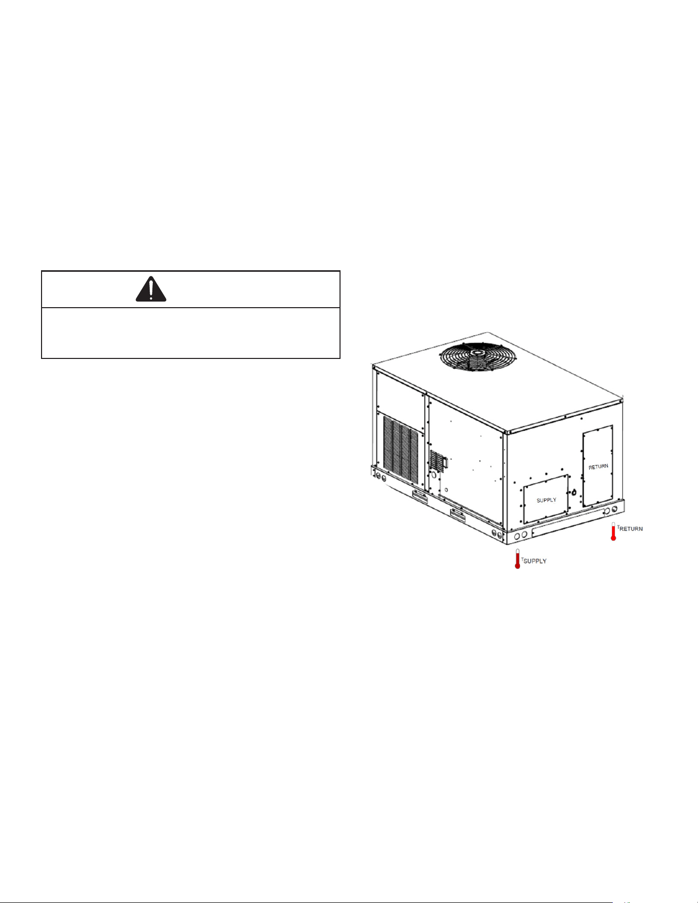
21
10. Remove regulator cover screw from the HI outlet
pressure regulator adjust tower and turn screw
clockwise to increase pressure, or counterclockwise
to decrease pressure.
11. Turn o all electrical power and gas supply to the
system.
12. Remove manometer hose from outlet pressure boss.
13. Turn outlet pressure test screw in to seal pressure
port (clockwise, 7 inlb minimum).
14. Turn on electrical power and gas supply to the
system.
15. Turn on system power and energize valve.
16. Using a leak detection solution or soap suds, check
for leaks at pressure boss screw. Bubbles forming
indicate a leak. SHUT OFF GAS AND FIX ALL
LEAKS IMMEDIATELY.
CAUTION
To prevent unreliable operation or equipment damage,
the gas manifold pressure must be as specified on the unit
rating plate. Only minor adjustments should be made by
adjusting the gas valve pressure regulator.
Main Burner Flame Check
Flames should be stable, soft and blue (dust may cause
orange tips but they must not be yellow) and extending
directly outward from the burner without curling, oating or
lifting o.
Gas Input (Natural Gas Only) Check
It is the responsibility of the contractor to adjust the gas
input to the unit.
To measure the gas input use a gas meter and proceed as
follows:
1. Turn o gas supply to all other appliances except the
unit.
2. With the unit operating, time the smallest dial on the
meter for one complete revolution. If this is a 2 cubic
foot dial, divide the seconds by 2; if it is a 1 cubic foot
dial, use the seconds as is. This gives the seconds
per cubic foot of gas being delivered to the unit.
3. INPUT=GAS HTG VALUE x 3600 / SEC. PER CUBIC
FOOT
Example: Natural gas with a heating value of 1000 BTU
per cubic foot and 34 seconds per cubic foot as determined
by Step 2, then:
Input = 1000 x 3600 / 34 = 106,000 BTU per Hour.
NOTE: BTU content of the gas should be obtained
from the gas supplier. This measured input must
not be greater than shown on the unit rating
plate.
Adjust input rate by varying the adjustment of the gas
pressure regulator on the gas valve. All adjustments
must be made with furnace operating at high re and at
normal operating temperature. A manometer should be
connected to the gas valve to verify pressure is within
the specied range (see following gures for manometer
connections). Clockwise rotation of the pressure regulator
screw increases pressure and gas ow rate. Turn screw
counterclockwise to decrease pressure and gas ow rate.
After adjustment the furnace temperature rise must be
within the range specied on the unit data plate.
Temperature Rise Check
Check the temperature rise through the unit by placing
thermometers in supply and return air registers as close
to the unit as possible. Thermometers must not be able to
sample temperature directly from the unit heat exchangers,
or false readings could be obtained.
1. All registers must be open; all duct dampers must be
in their nal (fully or partially open) position and the
unit operated for 15 minutes before taking readings.
2. The temperature rise must be within the range
specied on the rating plate.
Checking Temperature Rise
NOTE: Air temperature rise is the temperature
difference between supply and return air.
With a properly designed system, the proper amount of
temperature rise will normally be obtained when the unit
is operated at rated input with the recommended blower
speed.
If the correct amount of temperature rise is not obtained,
it may be necessary to change the blower speed. A higher
blower speed will lower the temperature rise. A slower
blower speed will increase the temperature rise.
NOTE: Blower speed MUST be set to give the
correct air temperature rise through the unit as
marked on the rating plate.
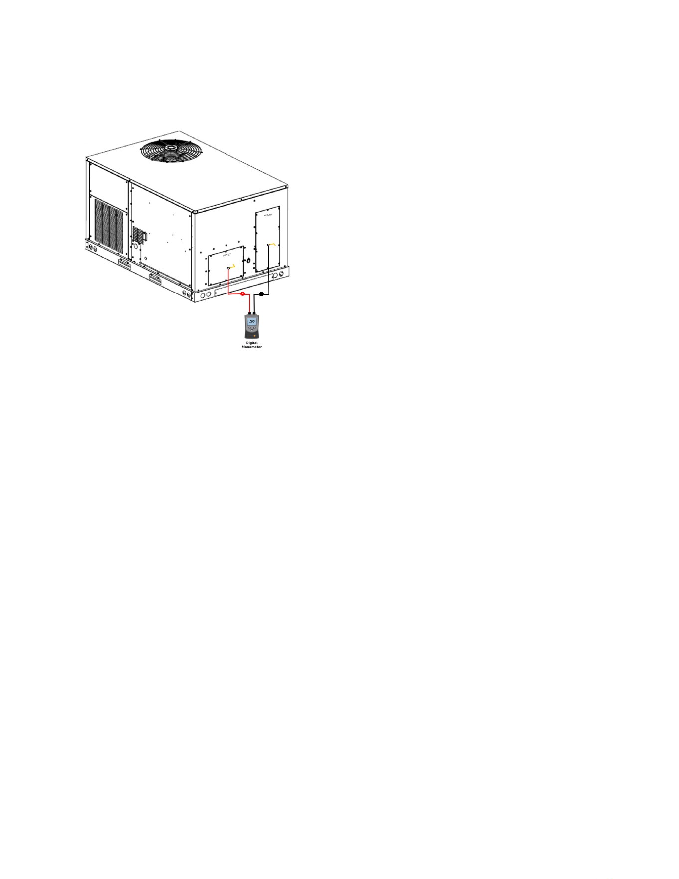
22
External Static Pressure Check
The total external static pressure must be checked on this
unit to determine if the airow is proper.
1. Using a digital manometer measure the static
pressure of the return duct at the inlet of the unit,
(Negative Pressure).
Total External Static
2. Measure the Static pressure of the supply duct,
(Positive Pressure).
3. Add the two readings together.
EXAMPLE:
static reading from return duct = .1” w.c.
static reading from supply duct = .3” w.c.
total external static pressure on this system = .4” w.c.
NOTE: Both readings may be taken
simultaneously and read directly on the
manometer if so desired.
4. Consult proper table for quantity of air.
If the external static pressure exceeds the maximum
allowable static, check for closed dampers, dirty lters,
undersized or poorly laid out ductwork.
Refer to airow table provided in the Appendix for details.
NORMAL SEQUENCE OF OPERATION
Heating
This unit has one (RS) Manual Reset Limit Control Switch.
Check the limit to make sure it has not tripped. The limit
may arrive at the job site tripped as a result of shipping
shock.
If the induced draft motor comes on, but the unit does
not attempt ignition, check if the ALS (Auxiliary High Limit
Control Switch) requires resetting.
1. With electricity and gas turned on, the system switch
in the “HEAT” or “AUTO” position and the fan switch
in the “AUTO” position, the thermostat will close the
circuit between unit terminals R and W (RW) when
the temperature falls below the thermostat setting.
2. D1 on IIC energizes induced draft motor contactor.
3. Induced draft motor contactor energizes the induced
draft motor.
4. Operation of the induced draft motor closes
the pressure switch PS located in the burner
compartment. Unless excessive temperatures or
shipping shock have opened high limit control ALS,
power is fed to the integrated ignition control, which
then initiates a 15second prepurge time delay.
During this period, the induced draft fan will clear the
combustion chamber of any residual gas.
5. After the pre-purge period, the ignition control
energizes the WlC gas valve and simultaneously
initiates a “three (3)try” spark ignition sequence.
6. When the burners are ignited, a minimum one (1)
microamp DC current will ow through the ame
between the sensor electrode and the grounded
burner.
7. When the controller proves that the ame has been
established, it will keep the gas valve energized and
discontinue the ignition spark.
8. If the control is unable to ignite the burners after its
initial attempt, it will initiate another purge and spark
sequence. A third purge and spark sequence will
be initiated if the second attempt is unsuccessful.
If the third attempt is unsuccessful, the controller
will close the gas valve and lock itself out. It may be
reset by momentarily interrupting power. This may be
accomplished by briey lowering the room thermostat
setpoint below room temperature, or by shutting o
the main power to the unit.
9. Integrated ignition control will close its normally open
contacts after a delay of approximately 30 seconds.
This action energizes the blower motor contactor and
starts the supply fan motor. Operation of the supply
fan circulates air across the heat exchanger and
delivers heated air to the conditioned space.
10. When the space temperature rises, the thermostat will
open RW. Opening RW will cause the gas valve to
close, and the furnace to shut down.
11. The furnace has three high temperature limit controls,
which can shut down the burner. They do not shut
down the induced draft motor.
Automatic Reset High Limit Control (LS)
Located in the burner compartment on the heat exchanger,
its sensing element projects through the blower section
bulkhead and senses the temperature at the rear of the
furnace. It will cycle the furnace o if the temperature
exceeds 100°F plus maximum rise.
Auxiliary High Limit Control (ALS)
Located in the blower compartment on the blower housing,
it senses air temperature within the blower compartment
and protects the lters from excessive temperature. It will
shut down the furnace if it senses excessive temperatures.
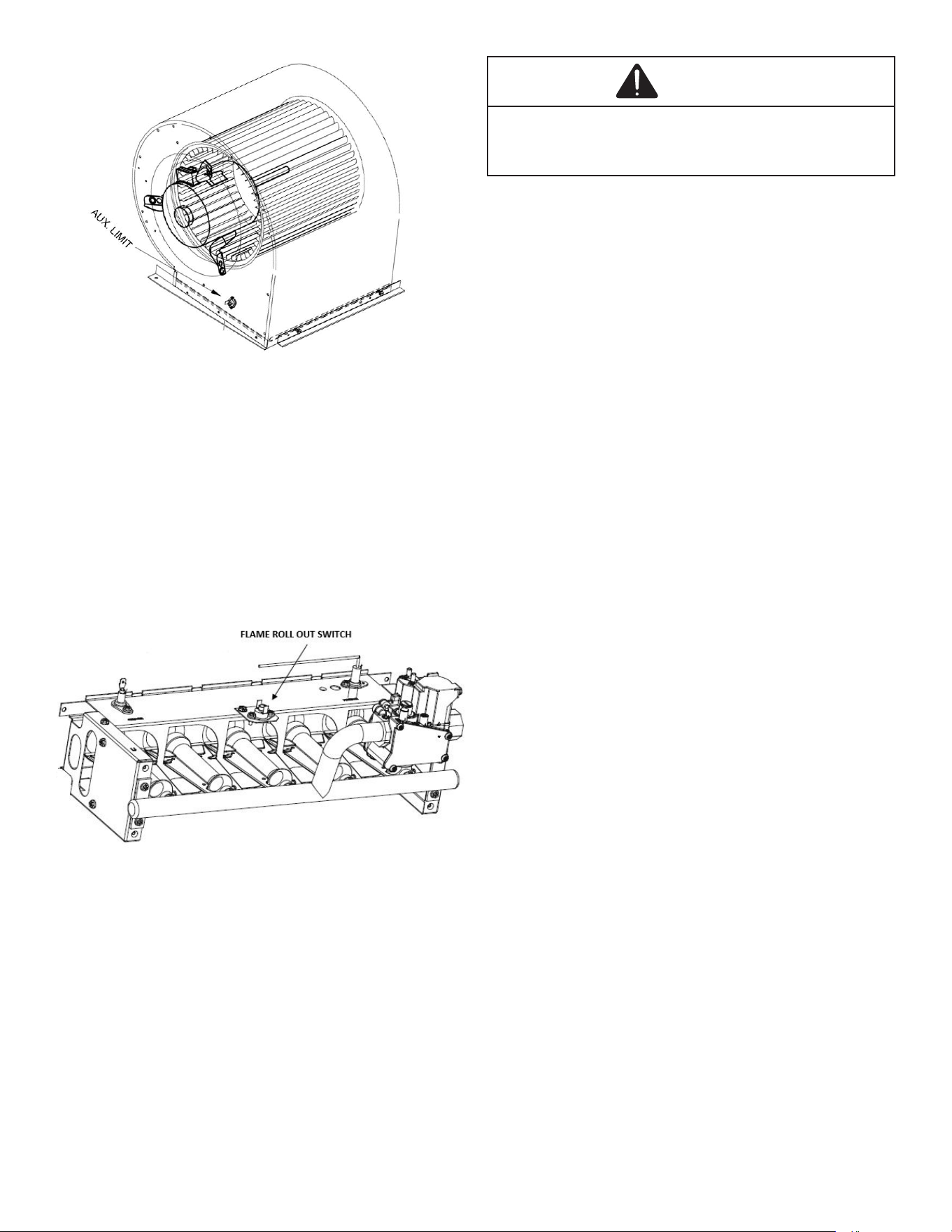
23
Auxiliary Limit Switch Location
Elevated temperatures at the control are normally caused
by blower failure. The reason for the shut down should be
determined and repaired prior to resetting.
Manual Reset Flame Rollout Control (RS)
Located in the burner compartment at the top of the burner
assembly, it senses high temperature that could occur if
the heat exchanger tubes were plugged and the ame was
rolling out instead of entering the tubes. It has a manual
pushbutton reset that cannot be actuated until the limit
control has cooled.
Flame Roll Out Switch Location
The reason for elevated temperatures at the control should
be determined and repaired prior to resetting this manual
reset control.
Unit Shutdown
1. Set the room heating setpoint to lowest setting.
2. Turn o the electrical power supply to the unit.
3. Remove the heat exchanger door on the side of the
unit by removing screws.
4. Move the gas control valve switch to the OFF position.
5. Close manual gas shut o valve external to the unit.
6. Replace the heat exchanger door on the unit.
7. If cooling and/or air circulation will be desired, turn ON
the electrical power.
WARNING
To avoid property damage, personal injury or death due to
fire or explosion, a qualified servicer must investigate the
reason for the rollout protection device to open before
manually resetting the rollout protection device.
Refrigeration System Checks
This unit is equipped with thermal expansion valves.
Ensure the holddown bolts on the compressor are secure
and have not vibrated loose during shipment. Check that
the vibration grommets have been installed and visually
check all piping for damage and leaks and repair if
necessary. The entire system has been factory charged
and tested, making it unnecessary to eld charge. Factory
refrigerant charge is shown on the unit’s nameplate.
To conrm charge levels or, if a leak occurs and charge
needs to be added to the system, it is recommended to
evacuate the system and recharge refrigerant to the unit’s
nameplate specications. This unit has been rated in the
cooling mode at the AHRI rated conditions of: indoor (80°F
db/67°F wb) and outdoor (95°F db). While operating at this
condition, the superheat should range from 9°F to 11°F for
each refrigeration circuit measured at the suction service
port located near the compressor.
Checking Subcooling
NOTE: Units with a TXV should be charged to
Subcooling only.
SUBCOOLING FORMULA = SATURATED LIQUID LINE
TEMPERATURE - LIQUID LINE TEMPERATURE
EXAMPLE:
a. Liquid Line Pressure = 417 PSI
b. Corresponding Temp. = 120°F
c. Thermometer on Liquid line = 109°F.
To obtain the amount of subcooling, subtract 109°F
from 120°F. The dierence is 11° subcooling. See the
specication sheet or technical information manual for the
design subcooling range for your unit.
Checking Superheat
EXAMPLE:
a. Suction Pressure = 143 PSI
b. Corresponding Temp. = 50°F
c. Thermometer on Suction Line = 59°F
To obtain the degrees temperature of superheat, subtract
50.0 from 59.0°F. The dierence is 9° Superheat. The 9°
Superheat would fall in the ± range of allowable superheat.
SUPERHEAT = SUCTION LINE TEMP - SAT. SUCTION
TEMP.
24
TXV Superheat Adjustment
NOTE: Superheat adjustments should not be made
until indoor ambient conditions have stabilized
and correct air flow (CFM) has been verified.
This could take up to 24 hours depending on
indoor temperature and humidity. Before checking
superheat, run the unit in cooling for 15-20
minutes
or until refrigerant pressure stabilizes.
NOTE: TXV adjustments should not exceed one
turn clockwise (CW) or counterclockwise (CCW)
from the factory setting.
Unscrew the cover from the expansion valve, locate the
adjustment screw, and turn clockwise (in) to increase
superheat or counterclockwise (out) to decrease
superheat. It is recommended to make small adjustments
at a time, 1/8 1/4 turn increments. Replace adjustment
cap. Wait a minimum of 15 minutes between adjustments
to allow time for the TXV and pressure to stabilize.
Refrigerant Charge Check
NOTE: For optimal performance, follow charging
instructions below.
Units with TXV
Single Stage Cooling Application: Refer to the Design
Superheat & Subcooling table.
Two-Stage Cooling Application: Run unit on Low Stage
cooling and refer to Design Superheat & Subcooling table.
1. Purge gauge lines. Connect service gauge manifold
to access ttings. Run system at least 10 minuets to
allow pressure to stabilize.
2. Temporarily install thermometer on liquid (small) line
near liquid line access tting with adequate contact
and insulate for best possible reading.
3. Check subcooling and superheat. System should
have a subcooling and superheat within the range
listed on the Design Superheat and Subcooling table.
a. If subcooling and superheat are low, adjust TXV
superheat, then check subcooling.
NOTE: To adjust superheat, turn the
valve stem clockwise to increase and
counterclockwise to decrease. Refer to
TXV Superheat Adjustment referenced in
this manual.
b. If subcooling is low and superheat is high,
add charge to raise subcooling then check
superheat.
c. If subcooling and superheat are high, adjust
TXV valve superheat, then check subcooling.
d. If subcooling is high and superheat is low, adjust
TXV valve superheat and remove charge to
lower the subcooling.
NOTE: Do NOT adjust the charge based
on suction pressure unless there is a
gross undercharge. If an under charge
is suspected, recover the charge, re-
evacuate the system, and recharge per
data plate. No adjustments should be
made if suspecting a charge issue.
4. Disconnect manifold set, installation is complete.
Model
IO SH
±2°F
IO SC
±1°F
Expansion
Device
Cooling
Stage
Outdoor
Ambient
GPGM560***31 16.5 13.0 TXV Low 82
Design Superheat & Subcool
NOTE: Subcooling should be measured at outdoor
liquid line.
NOTE: Superheat should be measured at
compressor suction line.
Cooling Operation
NOTE: Mechanical cooling cannot be reliably
provided at ambient temperatures below 60° F.
1. Turn on the electrical power supply to the unit.
2. Place the room thermostat selector switch in the
COOL position (or AUTO if available, and if automatic
changeover from cooling to heating is desired).
3. Set the room thermostat to the desired temperature.
Start-Up Procedure and Checklist
Begin with power turned o at all disconnects.
1. Turn thermostat system switch to “Cool,” and fan
switch to “Auto” and turn temperature setting as high
as it will go.
2. Inspect all registers and set them to the normal open
position.
3. Turn on the electrical supply at the disconnect.
4. Turn the fan switch to the “ON” position. The blower
should operate after a 7 second delay.
5. Turn the fan switch to “Auto” position. The blower
should stop after a 60 second delay.
6. Slowly lower the cooling temperature until the unit
starts. The compressor, blower and fan should now be
operating. Allow the unit to run 10 minutes, make sure
cool air is being supplied by the unit.
7. Turn the temperature setting to the highest position,
stopping the unit. The indoor blower will continue to
run for 60 seconds.
8. Turn the thermostat system switch to “OFF” and
disconnect all power when servicing the unit.
Refrigeration Sequence Check
1. 24VAC control voltage is provided by the control
transformer to terminal XS. The control voltage is
passed through any installed safety shutdown devices
such as the smoke detector before providing 24VAC
to terminals ES and R.
2. To simulate a mechanical call for cooling lower the
room cooling setpoint to a value below the current
room temperature. The cooling is energized when the
room temperature is above the setpoint for cooling.
25
3. UNIT WITH ECONOMIZER OPTION: The
compressor circuit is interlocked through the
economizer module. If the outdoor air enthalpy
(temperature and humidity) is not suitable for cooling,
the economizer will permit the compressor to be
energized.
4. The blower motor is operated to provide cool supply
air to the space.
5. Compressor contactor closes its contacts to provide
power to the compressor motor. In addition, the
condenser fan motor is energized through the
compressor contactor.
WARNING
BURN HAZARD!
DO NOT TOUCH! DISCHARGE LINE MAY BE HOT!
6. Check that the compressor is operating correctly.
The scroll compressors in these units MUST operate
in the proper rotation. To ensure the compressor
is operating in the correct direction, check the
compressor discharge line pressure or temperature
after the compressor is started.
The discharge pressure and discharge line temperature
should increase. If this does not occur and the compressor
is producing an exceptional amount of noise, perform the
following checks.
7. If the compressor is operating backward, disconnect
the unit power supply and lock it in the “OFF” position.
Switch two leads of the power supply at the unit
Single Point Power Block. Reconnect power and
check for compressor and condenser fan motor
operation.
8. With all safety devices closed, the system will
continue cooling operation until the room temperature
is satised.
9. Increasing the room cooling setpoint to a value above
the current room temperature will simulate a satised
thermostat. The compressor and the supply fan will
cycle o.
10. After a time delay of approximately 3 minutes, the
compressor control circuits will be ready to respond to
a subsequent call for cooling.
Refrigeration Performance Check
Check that compressor RLA corresponds to values shown
in Appendix B. RLA draw can be much lower than values
listed at low load conditions and low ambient condensing
temperatures. Values in Appendix B can slightly exceed
at high load conditions and high ambient condensing
temperatures.
Final System Checks
1. Check to see if all supply and return air grilles are
adjusted and the air distribution system is balanced
for the best compromise between heating and cooling.
2. Check for air leaks in the ductwork. See Sections on
Air Flow Adjustments.
3. Make sure the unit is free of “rattles”, and the tubing
in the unit is free from excessive vibration. Also make
sure tubes or lines are not rubbing against each other
or sheet metal surfaces or edges. If so, correct the
trouble.
4. Set the thermostat at the appropriate setting for
cooling and heating or automatic changeover for
normal use.
5. Be sure the Owner is instructed on the unit operation,
lter, servicing, correct thermostat operation, etc.
RDS Function
The mitigation system is a stationary device that detects
the presence of R32 refrigerant above 25% LFL using
refrigerant sensors and then initiates mitigation actions.
The mitigation system’s primary function is to reduce the
concentration of leaked R32 refrigerant to prevent serious
safety hazards. The mitigation actions are accomplished
by halting HVAC operation and continuing indoor blower
operation to provide airow. Once refrigerant concentration
reaches below a safe threshold, the unit will remain in
mitigation mode for ve minutes to evacuate any remaining
R32 refrigerant within the unit. Upon completion, the unit
will resume its normal operation.
RDS Operation
The mitigation system is controlled by a refrigerant
sensor(s), which is secured to a designated location(s) for
active monitoring. If a leak is detected, HVAC operation
is disabled and the indoor blower fan is activated,
providing airow at or above minimum required airow to
evacuate excess concentration. If a Zone Control system
is installed in the ductwork attached to this system, the
Zone controller must be powered through a Daikin Zoning/
Accessory PCB to ensure that the Zoning Dampers open
during mitigation mode to provide ventilation throughout
all ducting. If the unit is installed with a communicating
thermostat, the thermostat will display relevant alerts/
information concerning mitigation mode. Once sensors
read concentration levels below a safe threshold, a ve
minute timer will initiate. Once the time is over, the unit will
resume back to its normal operation. If the sensors detect
another concentration excess, the unit will go back into
mitigation mode and will repeat the same process.
MAINTENANCE
WARNING
ELECTRICAL SHOCK, FIRE OR EXPLOSION HAZARD
Failure to follow safety warnings exactly could result
in dangerous operation, serious injury, death or property
damage.
Improper servicing could result in dangerous operation,
serious injury, death or property damage.
• Before servicing, disconnect all electrical power to
furnace.
• When servicing controls, label all wires prior to
disconnecting. Reconnect wires correctly.
• Verify proper operation after servicing.
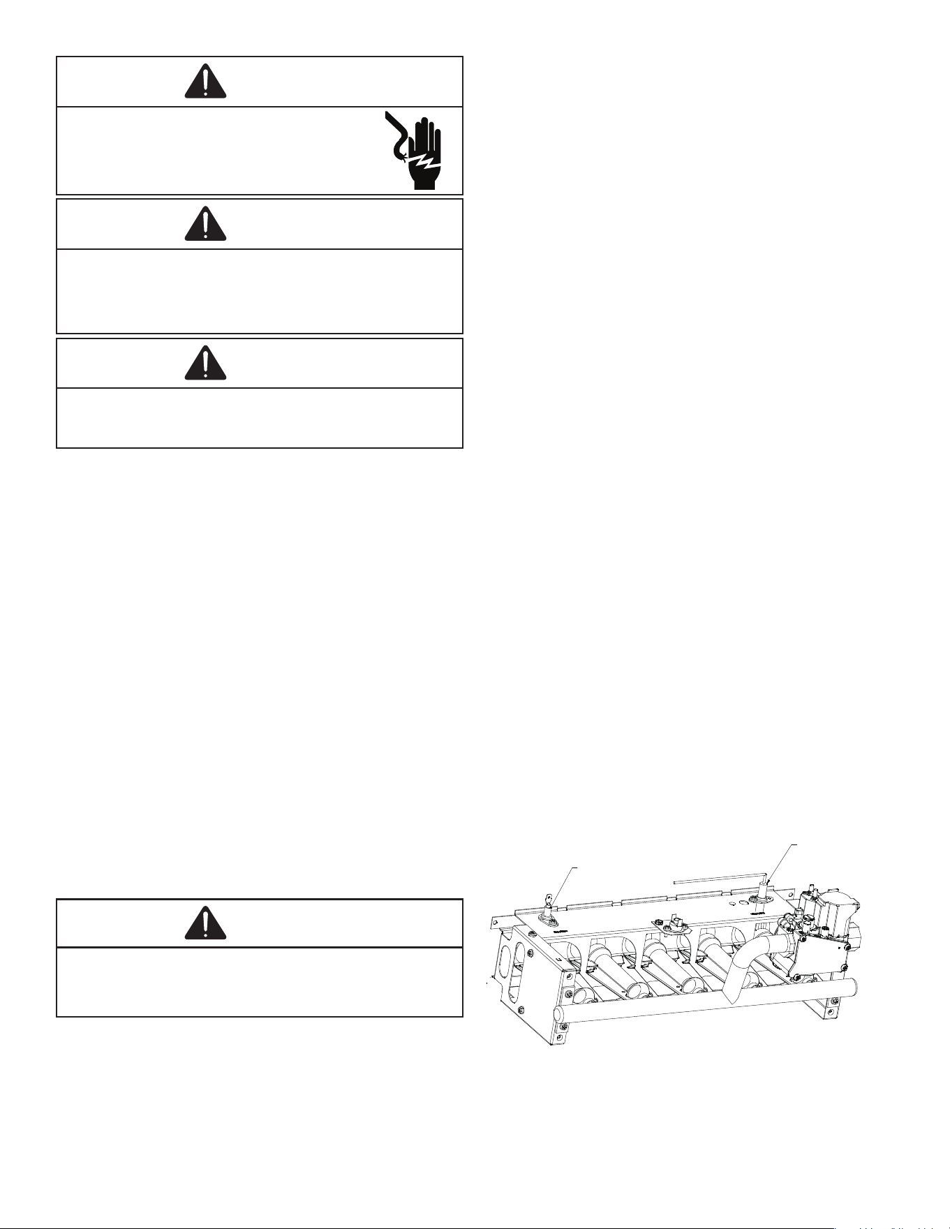
26
WARNING
HIGH VOLTAGE!
Disconnect all power before servicing or
installing this unit. Multiple power sources
may be present. Failure to do so may cause
property damage, personal injury or death.
WARNING
To prevent personal injury or death due to improper
installation, adjustment, alteration, service or maintenance,
refer to this manual. For additional assistance or
information, consult a qualified installer, servicer agency
or the gas supplier.
CAUTION
Sheet metal parts, screws, clips and similar items inherently
have sharp edges, and it is necessary that the installer and
service personnel exercise caution.
Preventive maintenance is the best way to avoid
unnecessary expense and inconvenience. Have this
system inspected at regular intervals by qualied service
personnel, at least twice a year. Routine maintenance
should cover the following items:
1. Tighten all set screws, and wire connections.
2. Clean evaporator and condenser coils mechanically
or with cold water, if necessary. Usually any fouling
is only matted on the entering air face of the coil and
can be removed by brushing.
3. Replace lters as needed (see below).
4. Check for blockage of condensate drain.
5. Check power and control voltages.
6. Check running amperage.
7. Check operating temperatures and pressures.
8. Check and adjust temperature and pressure controls.
9. Check and adjust damper linkages.
10. Check operation of all safety controls.
11. Examine gas furnaces (See below and the User’s
Information Manual).
12. Check condenser fans and tighten set screws.
Filters
CAUTION
To prevent property damage due to fire and loss of
equipment efficiency or equipment damage due to dust and
lint build up on internal parts, never operate unit without an
air filter installed in the return air system.
Every application may require a dierent frequency of
replacement of dirty lters. Filters must be replaced at least
every three (3) months during operating seasons.
Dirty lters are the most common cause of inadequate
heating or cooling performance. Filter inspection should be
made at least every two months; more often if necessary
because of local conditions and usage.
Dirty throwaway lters should be discarded and replaced
with a new, clean lter.
Cabinet Finish Maintenance
Use a ne grade automotive wax on the cabinet nish to
maintain the nish’s original high luster. This is especially
important in installations with extended periods of direct
sunlight.
Clean Outside Coil (Qualified Servicer Only)
The coil with the outside air owing over it should be
inspected annually and cleaned as frequently as necessary
to keep the nned areas free of lint, hair and debris.
Clean Indoor Coil (Qualified Servicer Only)
Before cleaning the indoor coil, A2L sensor must be
removed from the unit to avoid damage and contamination.
Air lters should also be removed before performing
maintenance. The coil with the ltered air owing over
it should be inspected and cleaned as frequently as
necessary to keep the nned areas free of debris. Coil
cleaning should be performed, utilizing an approved
cleaning method and cleaning agent, from inside-out
(opposite operating airow direction) to prevent damage
to the tube, n coil, and any other components. Prior to
resuming unit operation, ensure to reinstall the A2L sensor.
Condenser And Induced Draft Motors
Bearings on the condenser fan motors and the combustion
fan motor are permanently lubricated. No additional oiling
is required.
Flame Sensor (Qualified Servicer Only)
A drop in the ame current can be caused by a nearly
invisible coating on the ame sensor. This coating, created
by the fuel or combustion air supply, can be removed by
carefully cleaning the ame sensor with steel wool.
FLAME SENSOR
IGNITION ELECTRODE
Flame Sensor and Ignition Electrode Location
NOTE: After cleaning, the microamp signal should
be stable and in the range of 4 - 6 microamps DC.
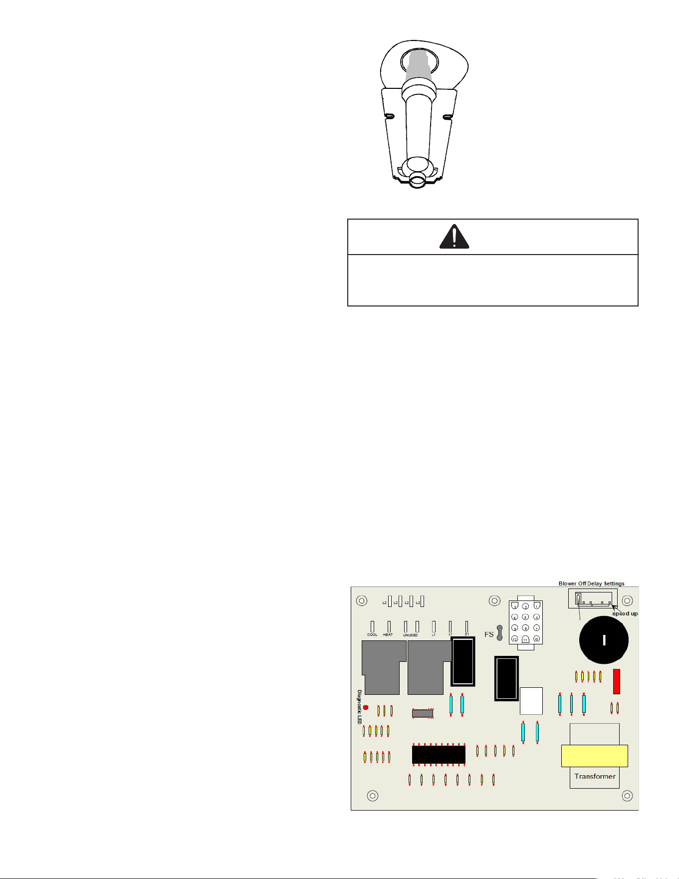
27
Flue Passages (Qualified Servicer Only)
At the start of each heating season, inspect and, if
necessary, clean the unit ue passage.
Lubrication
The fan shaft bearings, the supply fan motors, the
condenser fan motors and compressors are permanently
lubricated.
Inspection & Cleaning
All ue product carrying areas of the furnace, its vent
system, and main burners should be examined by a
qualied service agency, and cleaned if necessary, before
the start of each heating season. This examination is
necessary for continued safe operation. Particular attention
should be given to deterioration from corrosion or other
sources. This examination is accomplished in the following
manner.
1. Disconnect power to the unit and remove furnace
section access panel.
2. Remove burner assembly:
a. Disconnect the wires from the gas valve after
noting which wires are connected to each
terminal.
b. Disconnect wires from the ame rod and ignition
electrode.
c. Close manual gas shut o valve external to the
unit.
d. Disconnect the gas piping at the union.
e. The entire burner assembly can now be
removed from the unit.
NOTE: Use all screws that were removed; they are
necessary for safe and proper operation of the
unit.
3. Inspect and periodically clean the vent outlet (bird
screen) on the access panel.
NOTE: Periodic observation of the flame and a
log of C0
2
measurements are recommended. This
will aid in determining whether the furnace is
operating efficiently or if the furnace requires
cleaning.
Flames should be stable, soft and blue (dust may cause
orange tips but must not be yellow). The ames must
extend directly outward from the burner without curling,
oating or lifting o.
Check the burner flames for:
1. Good adjustment
2. Stable, soft and blue
3. Not curling, floating, or lifting off.
Burner Flame
WARNING
To avoid personal injury or death due to electric shock, do
not remove any internal compartment covers or attempt
any adjustment. Contact a qualified servicer at once if an
abnormal flame should develop.
At least once a year, prior to or during the heating season,
make a visual check of the burner ames.
NOTE: This will involve removing and reinstalling
the heat exchanger door on the unit, which is held
by two screws. If you are uncertain about your
ability to do this, contact a qualified servicer.
If a strong wind is blowing, it may alter the airow pattern
within the unit enough that an inspection of the burner
ames is not possible.
TROUBLESHOOTING
Ignition Control Error Codes
The following presents probable causes of questionable
unit operation. Refer to Diagnostic Indicator Chart for
an interpretation of the signal and to this section for an
explanation.
PCBAG123 DSI Control Board

28
Remove the control box access panel and note the number
of diagnostic LED ashes.
Internal Control Failure
If the integrated ignition control in this unit encounters an
internal fault, it will go into a “hard” lockout and turn o the
diagnostic LED. If diagnostic LED indicates an internal
fault, check power supply to unit for proper voltage, check
all fuses, circuit breakers and wiring. Disconnect electric
power for ve seconds. If LED remains o after restoring
power, replace control.
Abnormal Operation - Heating Codes
External Lockout (1 FLASH CODE)
An external lockout occurs if the integrated ignition control
determines that a measurable combustion cannot be
established within three (3) consecutive ignition attempts.
If ame is not established within the seven (7) second trial
for ignition, the gas valve is deenergized, 15 second inter
purge cycle is completed, and ignition is reattempted. The
control will repeat this routine three times if a measurable
combustion is not established. The control will then shut o
the induced draft blower and go into a lockout state.
If ame is established but lost, the control will energize
the circulator blower at the heat speed and then begin a
new ignition sequence. If ame is established then lost on
subsequent attempts, the control will recycle for four (4)
consecutive ignition attempts (ve attempts total) before
locking out.
The diagnostic fault code is 1 ash for a lockout due to
failed ignition attempts or ame dropouts. The integrated
control will automatically reset after one hour, or it can be
reset by removing the thermostat signal or disconnecting
the electrical power supply for over ve seconds. If the
diagnostic LED indicates an external lockout, perform the
following checks:
• Check the supply and manifold gas pressures
• Check the gas orices for debris
• Check gas valve for proper operation
• Check secondary limit
A dirty lter, excessive duct static, insucient air ow,
a faulty limit, or a failed circulator blower can cause
this limit to open. Check lters, total external duct
static, circulator blower motor, blower motor speed
tap (see wiring diagram) and limit. An interruption
in electrical power during a heating cycle may also
cause the auxiliary limit to open. The automatic reset
secondary limit is located on top of the circulator
blower assembly.
• Check rollout limit
If the burner ames are not properly drawn into the
heat exchanger, the ame rollout protection device
will open. Possible causes are restricted or blocked
ue passages, blocked or cracked heat exchanger, a
failed induced draft blower, or insucient combustion
air. The rollout protection device is a manual reset
limit located on the burner bracket. The cause of
the ame rollout must be determined and corrected
before resetting the limit.
• Check ame sensor
A drop in ame signal can be caused by nearly
invisible coating on the sensor. Remove the sensor
and carefully clean with steel wool.
• Check wiring
Check wiring for opens/shorts and miswiring.
IMPORTANT: If you have to frequently reset your
gas/electric package unit, it means that a problem
exists that should be corrected. Contact a
qualified servicer for further information.
Pressure Switch Stuck Open (2 FLASH CODE)
A pressure switch stuck open can be caused by a faulty
pressure switch, faulty wiring, a disconnected or damaged
hose, a blocked or restricted ue, or a faulty induced draft
blower. If the control senses an open pressure switch
during the prepurge cycle, the induced draft blower only
will be energized.
If the pressure switch opens after ignition has begun the
gas valve is deenergized, the circulator blower heat o
cycle begins, and the induced draft blower remains on.
The diagnostic fault code is two ashes.
Pressure Switch Stuck Closed (3 FLASH CODE)
A stuck closed pressure switch can be caused by a faulty
pressure switch or faulty wiring. If the control encounters
a pressure switch stuck closed, the induced draft blower
remains o. The diagnostic LED code for this fault is three
(3) ashes.
Open Thermal Protection Device (4 FLASH CODE)
If the primary limit switch opens, the gas valve is
immediately deenergized, the induced draft and air
circulating blowers are energized. The induced draft and
air circulator blowers remain energized until the limit switch
recloses. The diagnostic fault code for an open limit is four
(4) ashes.
A primary limit will open due to excessive supply air
temperatures. This can be caused by a dirty lter,
excessive duct static, insucient air ow, or a faulty limit.
Check lters, total external duct static, blower motor,
blower motor speed tap (see wiring diagram), and limit.
This limit will automatically reset once the temperature falls
below a preset level.
Flame Detected with Gas Valve Closed
(5 FLASH CODE)
If ame is detected with the gas valve deenergized, the
combustion and air circulator blowers are energized. The
diagnostic fault code is ve (5) ashes for this condition.
The control can be reset by removing the power supply
to the unit or it will automatically reset after one hour.
Miswiring is the probable cause for this fault.
29
Abnormal Operation - Cooling Codes
Short Cycle Compressor Delay (6 FLASH CODE)
The automatic ignition control has a builtin feature that
prevents damage to the compressor in short cycling
situations. In the event of intermittent power losses or
intermittent thermostat operation, the ignition control will
delay output to the compressor contactor for three minutes
from the time power is restored. (Compressor is o a total
of three minutes). The diagnostic LED will ash six (6)
times to indicate the compressor contactor output is being
delayed.
NOTE: Some electronic thermostats also have a
built-in compressor short cycle timer that may be
longer than the three minute delay given above.
If you are using an electronic thermostat and the
compressor has not started after three minutes,
wait an additional five minutes to allow the
thermostat to complete its short cycle delay time.
Recovery
When removing refrigerant from a system, either for
servicing or decommissioning, it is recommended good
practice that all refrigerants are removed safely. When
transferring refrigerant into cylinders, ensure that only
appropriate refrigerant recovery cylinders are employed.
Ensure that the correct number of cylinders for holding the
total system charge is available. All cylinders to be used
are designated for the recovered refrigerant and labeled
for that refrigerant (i.e. special cylinders for the recovery
of refrigerant). Cylinders shall be complete with pressure
relief valve and associated shut o valves in good working
order. Empty recovery cylinders are evacuated and, if
possible, cooled before recovery occurs.
The recovery equipment shall be in good working order
with a set of instructions concerning the equipment that
is at hand and shall be suitable for the recovery of the
ammable refrigerant. If in doubt, the manufacturer should
be consulted. In addition, a set of calibrated weighing
scales shall be available and in good working order. Hoses
shall be complete with leak free disconnect couplings and
in good condition.
The recovered refrigerant shall be processed according
to local legislation in the correct recovery cylinder,
and the relevant waste transfer note arranged. Do not
mix refrigerants in recovery units and especially not in
cylinders.
If compressors or compressor oils are to be removed,
ensure that they have been evacuated to an acceptable
level to make certain that ammable refrigerant does not
remain within the lubricant. The compressor body shall not
be heated by an open ame or other ignition sources to
accelerate this process. When oil is drained from a system,
it shall be carried out safely.
Charging Procedures
In addition to conventional charging procedures, the
following requirements shall be followed.
• Ensure that contamination of dierent refrigerants
does not occur when using charging equipment.
• Hoses or lines shall be as short as possible to
minimize the amount of refrigerant contained in them.
• Cylinders shall be kept in an appropriate position
according to the instructions.
• Ensure that the REFRIGERATING SYSTEM is
grounded prior to charging the system with refrigerant.
• Extreme care shall be taken not to overll the
REFRIGERATING SYSTEM.
Prior to recharging the system, it shall be pressure
tested with the appropriate purging gas. The system shall
be leaktested on completion of charging but prior to
commissioning. A follow up leak test shall be carried out
prior to leaving the site.
NOTE: “Earthing” is defined as achieving an earth
ground by connecting the equipment’s supplied
grounding lug to the earth. This should be
verified by a certified technician.
Servicing Measures for the Refrigerant Detection
System
Before servicing, identify the mode of operation of the
system by reading the LED ashing pattern on the PCB
within the control box and matching the LED ashing
pattern with mode of operation in the REFRIGERANT
DETECTION SYSTEM TROUBLESHOOTING GUIDE on
the wiring diagram which is attached on the back side of
the control box panel (RDS PCB Fault Code table). After
identifying the mode of operation, take recommended
actions as specied in the Recommended Actions for PCB
LED Flashing Codes table.
REFRIGERANT SENSORS for REFRIGERANT
DETECTION SYSTEMS shall only be replaced with
sensors specied by the manufacturer. If REFRIGERANT
SENSOR requires replacement, please replace with
Sensata R32 Sensor PN#RGD00ML12 (Daikin
PN#SER2A08012).
MODE LED FLASHING PATTERN
NORMAL OPERATION
SLOW LED FLASHING PATTERN
(2 SECONDS ON 2 SECONDS OFF)
R-32 LEAK ALARM
FAST LED FLASHING PATTERN
DELAY MODE
LED WILL BE ON CONTINUOUSLY
SYSTEM
VERIFICATION MODE
FAST LED FLASHING PATTERN
CONTROL BOARD INTERNAL
FAULT
LED WILL FLASH 2 TIMES AND THEN
BE OFF FOR 5 SECONDS
R32 SENSOR
COMMUNICATION FAULT
LED WILL FLASH 3 TIMES AND THEN
BE OFF FOR 5 SECONDS
R32 SENSOR FAULT
LED WILL FLASH 4 TIMES AND THEN
BE OFF FOR 5 SECONDS
LED STATUS
RDS PCB Fault Code Table
30
MODE DEFINITION LED FLASHING PATTERN RECOMMENDED ACTIONS NOTES
1 Normal Operaon No faults to report.
Slow LED flashing paern
(2 seconds on and 2 seconds off)
No acons needed.
2 R32 Leak Alarm R32 leak is currently being detected. Fast LED Flashing Paern
A technician will need to find the refrigerant leak and
address it. Unit shall be thawed before servicing.
In terms of the controls, no acon is needed. The
controls and sensor are working fine.
3 Delay Mode
Aer R32 leak or alarm has been
cleared, the unit will remain in alarm
mode for 5 minutes before returning to
normal operaon.
LED will be on c
onnuously
No acon needed - If the system was previously experiencing an
actual R32 Leak, the refrigerant can no longer be detected by
the sensor meaning it's either gone and the system won't work
anymore or there was a false alarm. If the system was
experiencing a Fault, the fault is gone and the system will return
to normal operaon in 5 min.
Aer any alarm or fault, it is required to remain in
R32 migaon mode for 5 minutes.
4
System
Verificaon Mode
Manual test run by contractor to
simulate R32 Leak Alarm (test will last
for 5 minutes max).
Fast LED Flashing Paern No acons needed.
To enter system verificaon test mode, press the
buon on the control 2 mes within 5 seconds. The
control will enter a simulated R32 Leak Alarm state
and remain
in that mode for 5 minutes. Aer 5
minutes, the control will return to Normal
Operaon automacally. If the contractor wants to
end the test early they need to press the buon one
me.
5
Control Board
Internal Fault
Control board has detected an issue
with the R32 detecon system.
LED will flash 2 mes and then be
off for 5 seconds, before repeang
paern
1) Unplug and plug the R32 sensor back in. Cycle power to the
system.
2) If the control is in "Normal Operaon" or "Delay Mode",
there is no more issue. If not, connue with diagnoscs
3) Unplug R32 sensor and leave unplugged. Cycle power to the
system
4) If t
he control sll displays "Control Board Internal Fault" (2
flash paern), replace the control. If the control now displays
"R32 Sensor Communicaon Fault" (3 flash paern), replace the
sensor.
This error could indicate an on board relay failure o
r
a short with the sensor communicaons. A sensor
communicaon short could occur on the board
itself or external to the board. These steps will
determine if the error is on the board or external to
the board.
6
R32 Sensor
Communicaon Fault
Control board does not have
communicaons with R32 sensor.
LED will flash 3 mes and then be
off for 5 seconds, before repeang
paern
1) Unplug and plug the R32 sensor back in. Cycle power to the
system.
2) If control is in "Normal Operaon" or "Delay Mode", there is
no more issue. If not, connue with diagnoscs.
3) If the control sll displays "R32 Sensor Communicaon Fault"
(3 flash paern), replace both the sensor and the PCB.
If the control cannot talk to the sensor there could
be a problem with the sensor, a problem with the
sensor harness or a problem internal to the control.
The field will not be able to measure anything to
reliably fix this error assuming the connector is
properly secured to the control. Replacing both is
the only opon.
7 R32 Sensor Fault
R32 Sensor has reported an internal
issue.
LED will flash 4 mes and then be
off for 5 seconds, before repeang
paern
Replace R32 sensor.
Communicaons to the sensor are
perfectly fine. The sensor itself is reporng an
internal fault.
LED TROUBLESHOOT STATUS
TROUBLESHOOTING CODE
warning; flammable materials
service indicator; read technical
manual
operator's manual; operating
instructions
warning; low burning velocity
material
UN GHS flame symbol
Marking Symbol Table
Recommended Actions for PCB LED Flashing Codes Table
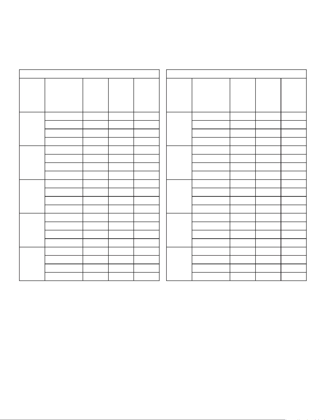
31
APPENDIX A BLOWER PERFORMANCE TABLES
Horizontal
Speed
Tap
External
Static
Pressure
(ESP), in
W.C.
SCFM RPM BHP
T1* 0.2 1190 605 0.16
0.4 1055 685 0.18
0.6 915 755 0.21
0.8 790 820 0.22
T2** 0.2 2005 845 0.61
0.4 1915 895 0.65
0.6 1820 940 0.68
0.8 1740 990 0.72
T3 0.2 2005 845 0.61
0.4 1915 895 0.65
0.6 11820 940 0.68
0.8 1740 990 0.72
T4 0.2 1990 840 0.6
0.4 1900 890 0.64
0.6 1805 935 0.67
0.8 1720 990 0.71
T5 0.2 2250 925 0.88
0.4 2170 960 0.91
0.6 2080 1005 0.96
0.8 1995 1045 0.99
5 TON
MODELS: GPGM56014031
STANDARD STATIC DRIVE
BURNERS HIGH FIRE INPUT: 140,000 BTU/HR
NOTE: T1 VALUES ARE FOR FAN MODE OR PART LOAD ONLY. T2 VALUES ARE FOR PART LOAD ONLY.
Downow
Speed
Tap
External
Static
Pressure
(ESP), in
W.C.
SCFM RPM BHP
T1* 0.2. 1135 620 0.16
0.4 1000 775 0.19
0.6 865 780 0.2
0.8 750 845 0.23
T2** 0.2 1910 870 0.63
0.4 1825 925 0.67
0.6 1735 970 0.7
0.8 1655 1020 0.74
T3 0.2 1910 870 0.63
0.4 1825 925 0.67
0.6 1735 970 0.7
0.8 1655 1020 0.74
T4 0.2 1895 865 0.62
0.4 1810 920 0.66
0.6 1720 965 0.69
0.8 1640 1020 0.73
T5 0.2 2145 955 0.91
0.4 2065 990 0.94
0.6 1980 1035 0.99
0.8 1900 1075 1.02
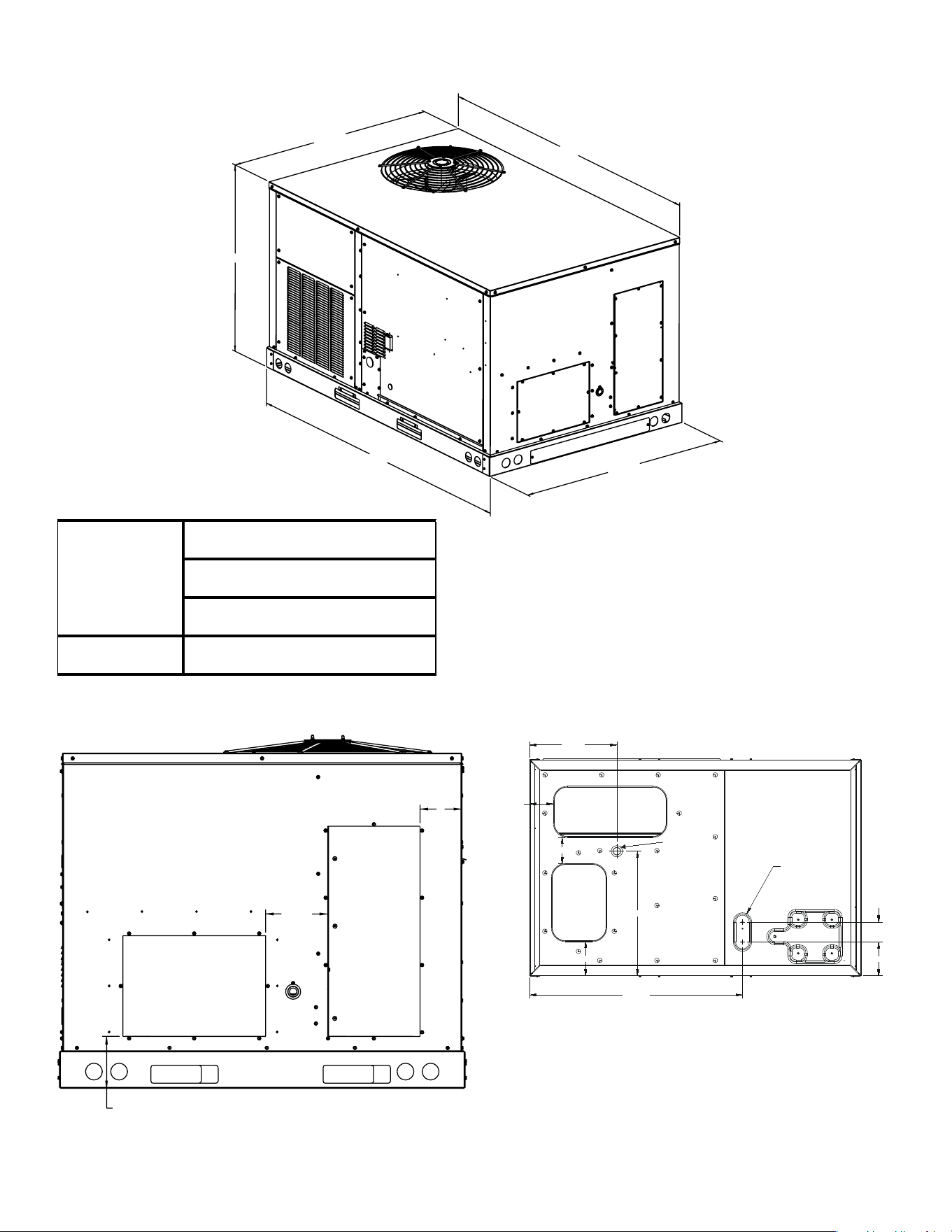
32
APPENDIX C UNIT DIMENSIONS
5-7/8
7-5/8
19-1/2
27-3/4
5-5/16
47-9/16
7-1/2
4-1/2
BOTTOM VIEW OF UNIT
DRAIN
THRU
CURB
LOCATION
EMBOSS
FOR
THRU
THE
BASE
UTILITIES
RETURN
11” X 25”
SUPPLY
12” X 17”
Horizontal Discharge
Vertical Discharge
NOTE: Refer to IOD-7019 included in the literature pack for installing horizontal duct covers.
"A"
475/8"
733/8"
485/16"
74"
5
6-3/16
73/8
SUPPLY
12" X 17"
RETURN
11" X 25"
5 TON
Tonnage
UNIT HEIGHT
DIM "A"
GPGM56014031
43-1/2"
33
APPENDIX D MIN-MAX AIRFLOW
UNIT
HEAT
RANGE
HIGH FIRE RATE
BTU/HR
HEATING
MINIMUM
SCFM
COOLING
MINIMUM
SCFM
MAXIMUM
SCFM
GPGM56014031 HIGH 135,000 1615 1500 2500
AIR FLOW RANGE FOR HIGH STAGE
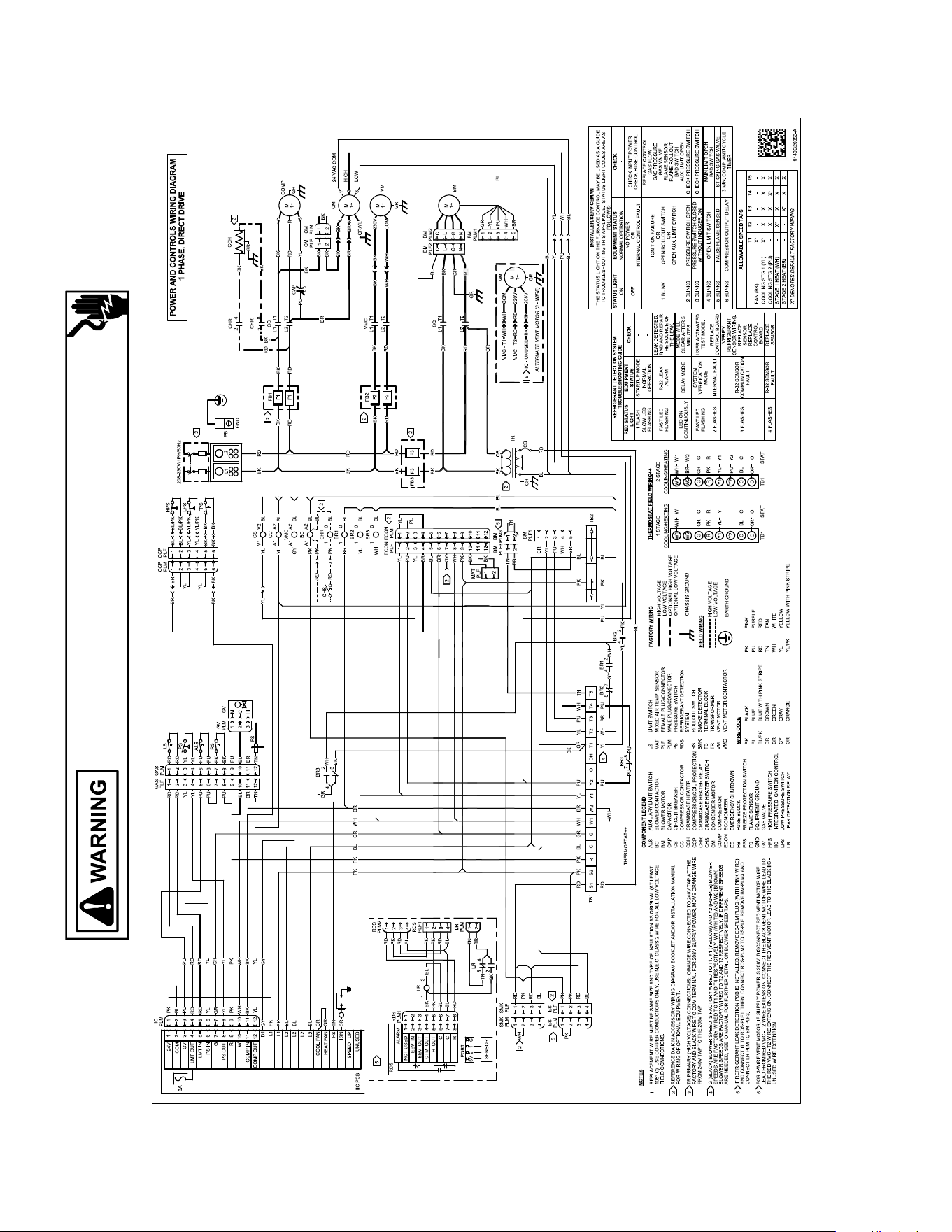
34
Wiring is subject to change. Always refer to the wiring diagram on the unit for the most uptodate wiring.
HIGH VOLTAGE!
DISCONNECT ALL POWER BEFORE SERVICING OR INSTALLING THIS
UNIT. MULTIPLE POWER SOURCES MAY BE PRESENT. FAILURE TO
DO SO MAY CAUSE PROPERTY DAMAGE, PERSONAL INJURY OR DEATH.
WIRING DIAGRAM
GPGM56014031
35
START-UP CHECKLIST
Residen�al Package - (Indoor Sec�on)
ELECTRICAL
Line Voltage (Measure L1 and L2 Voltage) L1 - L2
Secondary Voltage (Measure Transformer Output Voltage) R - C
Blower Amps
Heat Strip 1 - Amps
Heat Strip 2 - Amps
BLOWER EXTERNAL STATIC PRESSURE
Return Air Sta�c Pressure IN. W.C.
Supply Air Sta�c Pressure IN. W.C.
Total External Sta�c Pressure (Ignoring +/- from the reading above, add total here) IN. W.C.
TEMPERATURES
Return Air Temperature (Dry bulb / Wet bulb
) DB °F WB °F
DB °F WB °F
Hea�ng Supply Air Temperature DB °F
Temperature Rise DB °F
Delta T (Difference between Supply and Return Temperatures) DB °F
GAS PRESSURES
Gas Inlet Pressure IN. W.C.
Gas Manifold Pressure (Low Fire) IN. W.C.
Gas Manifold Pressure (High Fire) IN. W.C.
Gas Type (NG) = Natural Gas / (LP) = Liquid Propane
Residen�al Package - (Outdoor Sec�on)
ELECTRICAL
Supply Voltage (Measure L1 and L2 Voltage) L1 - L2
Compressor Am
ps
Condenser Fan Amps
PRESSURES / TEMPERATURES
Suc�on Circuit (Pressure / Suc�on Line Temperature) PSIG TEMP °F
Liquid Circuit (Pressure / Liquid Temperature) PSIG TEMP °F
Outdoor Air Temperature (Dry bulb / Wet bulb) DB °F WB °F
SUPERHEAT / SUBCOOLING SH SC
Addi�onal Checks
Check wire rou�ngs for any rubbing
Check product for proper draining
Check for kinked pressure switch tubing.
Check flue elbow for alignment and clamp �ghtness.
Ch
eck screw �ghtness on blower wheel.
Check factory wiring and wire connec�ons.
Check screw �ghtness on Outdoor Motor and Blade
Check product for proper clearances as noted by installa�on instruc�ons
°F to °C formula: (°F - 32) divided by 1.8 = °C °C to °F formula: (°C mul�plied by 1.8) + 32 = °F
Model Number
Serial Number
Cooling Supply Air Temperature (Dry bulb / Wet bulb)
36
CUSTOMER FEEDBACK
We are very interested in all product comments.
Please ll out the feedback form on one of the following links:
Goodman
®
Brand Products: (http://www.goodmanmfg.com/about/contactus).
Amana
®
Brand Products: (http://www.amanahac.com/aboutus/contactus).
You can also scan the QR code on the right for the product brand
you purchased to be directed to the feedback page.
GOODMAN
®
BRAND
AMANA
®
BRAND
Our continuing commitment to quality products may mean a change in specications without notice.
Daikin Comfort Technologies Manufacturing, Inc.
19001 Kermier Rd., Waller, TX 77484
www.goodmanmfg.com
© 2024, 2025 Daikin Comfort Technologies Manufacturing, Inc.