Service and Troubleshooting
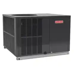
GPCM3 13.4 SEER(2) Cooling, *PHM3 13.4 SEER(2) Heat Pump
& *PHM5 15.2 SEER(2) Heat Pump Multi Position Package Unit
with R-32
RS6300018
April 2025
Pride and workmanship go into every product to provide
our customers with quality products. It is possible, however,
that during its lifetime a product may require service.
Products should be serviced only by a qualied service
technician who is familiar with the safety procedures
required in the repair and who is equipped with the proper
tools, parts, testing instruments and the appropriate service
manual. REVIEW ALL SERVICE INFORMATION IN THE
APPROPRIATE SERVICE MANUAL BEFORE
BEGINNING REPAIRS.
TABLE OF CONTENTS
IMPORTANT INFORMATION ........................................ 2
PRODUCT IDENTIFICATION ........................................ 4
SYSTEM OPERATION ................................................... 6
SCHEDULED MAINTENANCE ..................................... 10
SERVICING .................................................................... 12
CHECKING VOLTAGE ............................................ 12
CHECKING WIRING................................................. 12
CHECKING THERMOSTAT AND WIRING ............ 12
CHECKING TRANSFORMER AND CONTROL
CIRCUIT .................................................................... 13
CHECKING CONTACTOR AND/OR RELAYS ........ 14
CHECKING CONTACTOR CONTACTS.................. 14
CHECKING LOW PRESSURE CONTROL ............. 14
CHECKING HIGH PRESSURE CONTROL ............ 14
CHECKING INTERNAL OVERLOAD ...................... 15
CAPACITOR, RUN .................................................... 15
MODELS EQUIPPED WITH A HARD START
DEVICE...................................................................... 15
RELAY, START .......................................................... 16
TESTING COIL RELAY ............................................ 16
TESTING CONTACTS RESISTANCE ..................... 16
TESTING CONTACTS VOLTAGE ........................... 16
CAPACITANCE CHECK (MFD) ............................... 16
CHECKING FAN AND BLOWER MOTOR
WINDINGS (PSC MOTORS) .................................... 17
CHECKING EEM MOTORS .................................... 17
CHECKING ECM MOTORS ..................................... 17
CHECKING ECM MOTOR WINDINGS ................... 18
CHECKING COMPRESSOR ................................... 19
RESISTANCE TEST ................................................. 19
GROUND TEST ........................................................ 19
UNLOADER TEST PROCEDURE .......................... 20
© 2025 Daikin Comfort Technologies Manufacturing, Inc.
Brand
®
is a registered trademark of Maytag Corporation or its related companies and is used under license. All rights reserved.
Only personnel that have been trained to install, adjust,
service, maintenance or repair (hereinafter, “service”)
the equipment specified in this manual should service the
equipment.
This equipment is not intended for use by persons
(including children) with reduced physical, sensory or
mental capacities, or lack of experience and knowledge,
unless they have been given supervision or instruction
concerning use of the appliance by a person responsible
for their safety.
Children should be supervised to ensure that they do not
play with the equipment.
The manufacturer will not be responsible for any injury
or property damage arising from improper supervision,
service or service procedures. If you service this unit, you
assume responsibility for any injury or property damage
which may result. In addition, in jurisdictions that require
one or more licenses to service the equipment specified in
this manual, only licensed personnel should service the
equipment. Improper supervision, installation, adjustment,
servicing, maintenance or repair of the equipment specified
in this manual, or attempting to install, adjust, service
or repair the equipment specified in this manual without
proper supervision or training may result in product
damage, property damage, personal injury or death.
WARNING
WARNING
Do not bypass safety devices.
NOTE: *PHM3 and *PHM5 models apply to both
Amana® Brand and Goodman products only.
IMPORTANT INFORMATION
2
OUTSIDE THE U.S., call 1-713-861-2500.
(Not a technical assistance line for dealers.) Your telephone company will bill you for the call.
WARNING
HIGH VOLTAGE
Disconnect all power before servicing or
installing this unit. Multiple power sources
may be present. Failure to do so may cause
property damage, personal injury or death.
WARNING
This unit should not be connected to, or used in conjunction
with, any devices that are not listed in the applicable
product specifications as acceptable for use with thus unit
or have not been tested and approved by the manufacturer.
Serious property damage or personal injury, reduced unit
performance and/or hazardous conditions may result from
the use of devices that have not been approved or certified
by the manufacturer.
SAFE REFRIGERANT HANDLING
While these items will not cover every conceivable
situation, they should serve as a useful guide.
WARNING
Refrigerants are heavier than air. They can “push out” the
oxygen in your lungs or in any enclosed space. To avoid
possible difficulty in breathing or death:
• Never purge refrigerant into an enclosed room or
space. By law, all refrigerant must be reclaimed.
• If an indoor leak is suspected, thoroughly ventilate the
area before beginning work.
• Liquid refrigerant can be very cold. To avoid possible
frostbite or blindness, avoid contact with refrigerant
and wear gloves and goggles. If liquid refrigerant does
contact your skin or eyes, seek medical help immediately.
• Always follow EPA regulations. Never burn refrigerant,
as poisonous gas will be produced.
WARNING
To avoid possible injury, explosion or death, practice safe
handling of refrigerants.
WARNING
The compressor POE oil for R-32 units is extremely
susceptible to moisture absorption and could cause
compressor failure. Do not leave system open to atmosphere
any longer than necessary for installation.
UNLOADER TEST PROCEDURE ........................... 20
OPERATION TEST ................................................... 20
LOCKED ROTOR TEST .......................................... 21
TESTING CRANKCASE HEATER ........................... 21
CHECKING CRANKCASE HEATER
THERMOSTAT .......................................................... 21
CHECKING REVERSING VALVE AND SOLENOID ... 21
TROUBLESHOOTING THE REVERSING VALVE
FOR ELECTRICAL FAILURE .................................. 21
TROUBLESHOOTING MECHANICAL FAILURES
ON A REVERSING VALVE BY PRESSURE ........... 21
TROUBLESHOOTING MECHANICAL FAILURES
ON A REVERSING VALVE BY TEMPERATURE .... 22
TESTING DEFROST CONTROL ............................. 22
TESTING DEFROST THERMOSTAT ...................... 23
(OPTIONAL ELECTRIC HEATERS) ........................ 23
CHECKING HEATER ELEMENTS .......................... 23
REFRIGERATION REPAIR PRACTICE .................. 23
BRAZING MATERIALS............................................. 23
STANDING PRESSURE TEST (RECOMMENDED
BEFORE SYSTEM EVACUATION) ........................ 24
LEAK TESTING (NITROGEN OR
NITROGEN-TRACED) .............................................. 24
SYSTEM EVACUATION ........................................... 25
DEEP VACUUM METHOD (RECOMMENDED) ..... 25
TRIPLE EVACUATION METHOD (ALTERNATE) ... 25
CHARGING ............................................................... 26
CHECKING COMPRESSOR EFFICIENCY ............ 26
THERMOSTATIC EXPANSION VALVE ................... 26
OVERFEEDING ........................................................ 30
UNDERFEEDING ..................................................... 30
SUPERHEAT ............................................................. 30
CHECKING SUBCOOLING ..................................... 30
CHECKING EXPANSION VALVE OPERATION ..... 31
FIXED ORIFICE RESTRICTION DEVICES ........... 31
CHECKING RESTRICTED LIQUID LINE ............... 31
REFRIGERANT OVERCHARGE ............................ 32
NON-CONDENSABLES ........................................... 32
COMPRESSOR BURNOUT ..................................... 32
CHECKING EXTERNAL STATIC PRESSURE ....... 33
TROUBLESHOOTING .................................................. 37
WIRING DIAGRAMS ..................................................... 47
IMPORTANT NOTICES
RECOGNIZE SAFETY SYMBOLS, WORDS AND
LABELS
WARNING
To prevent the risk of property damage, personal injury or
death, do not store combustible materials or use gasoline
or other flammable liquids or vapors in the vicinity of this
appliance.
IMPORTANT INFORMATION
3
WARNING
To avoid possible explosion:
• Never apply flame or steam to a refrigerant cylinder. If
you must heat a cylinder for faster charging, partially
immerse it in warm water.
• Never fill a cylinder more than 80% full of liquid
refrigerant.
• Never add anything other than R-32 to an R-32 cylinder
or R-32 to an R-32 cylinder. The service equipment used
must be listed or certified for the type of refrigerant
used.
• Store cylinders in a cool, dry place. Never use a
cylinder as a platform or a roller.
WARNING
To avoid possible explosion, use only returnable (not
disposable) service cylinders when removing refrigerant
from a system.
• Ensure the cylinder is free of damage which could lead
to a leak or explosion.
• Ensure the hydrostatic test date does not exceed 5
years.
• Ensure the pressure rating meets or exceeds 400 lbs.
When in doubt, do not use cylinder.
WARNING
All maintenance staff and others working in the local area
shall be instructed on the nature of work being carried out.
Work in confined spaces shall be avoided.
WARNING
The area shall be checked with an appropriate refrigerant
detector prior to and during work, to ensure the technician
is aware of potentially toxic or flammable atmospheres.
Ensure that the leak detection equipment being used is
suitable for use with all applicable refrigerants.
WARNING
If any hot work is to be conducted on the refrigerating
equipment or any associated parts, appropriate fire
extinguishing equipment shall be available to hand.
WARNING
Ensure that the area is in the open or that it is adequately
ventilated before breaking into the system or conducting
any hot work. A degree of ventilation shall continue during
the period that the work is carried out. The ventilation
should safely disperse any released refrigerant and
preferably expel it externally into the atmosphere.
WARNING
In the inspection and servicing of the unit, any damaged or
faulty sealed electrical component or intrinsically safe
components are to be replaced.
WARNING
Units not to be installed in a room of less than the minimum
stated area below.
Minimum Room
Area
Ft² 164.5
M² 15.3
WARNING
Before completion of any maintenance, ensure that all
cabling and wiring will not be subject to wear, corrosion,
excessive pressure, vibration, sharp edges or any other
adverse environmental effects.
WARNING
Do not use means to accelerate the defrosting process or to
clean, other than those recommended by the manufacturer.
The appliance shall be stored in a room without
continuously operating ignition sources. Do not pierce or
burn. Be aware that refrigerants may not contain odor.
WARNING
Unit not to be installed in an unventilated area.
WARNING
Work shall be undertaken under a controlled procedure
so as to minimize the risk of flammable gas or vapor
being present while work is being performed. No person
carrying out work in relation to the refrigerant containing
components of the system shall use any sources of ignition
in such a manner that may lead to the risk of fire or
explosion.
PRODUCT IDENTIFICATION
4
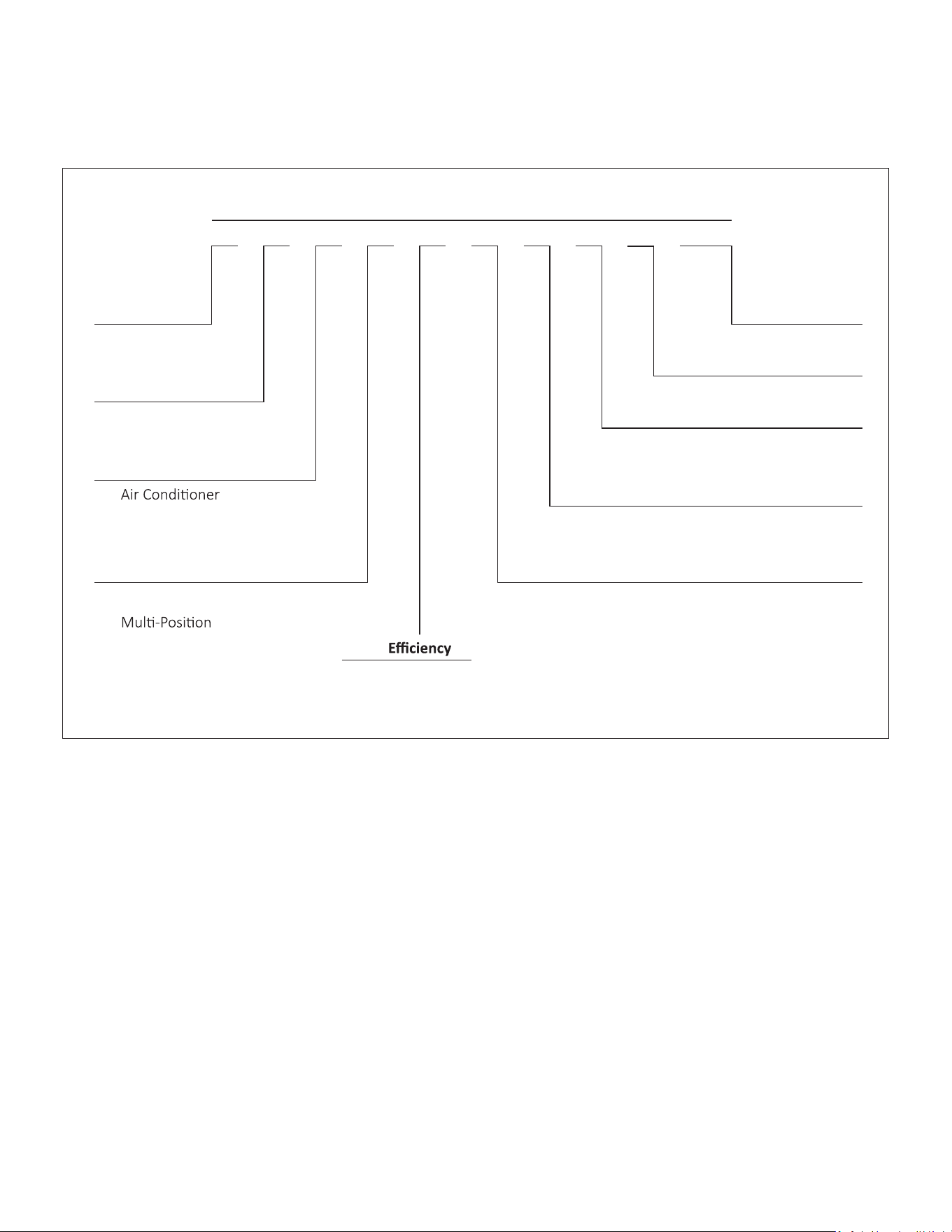
NOMENCLATURE
The model number is used for positive identication of component parts used in manufacturing. Please use this number
when requesting service or parts information.
G P H H 5 36 3 1 A A
1 2 3 4 5 6,7 8 9
10
11
Brand Minor Revision
G Goodman Brand A
Major Revision
Product Category
A
P Packaged Unit
Electrical
1 208/230 V, 1 Phase, 60 Hz
Unit Type
C
Refrigerant
H Heat Pump
3 R-32
Air Flow Nominal Capacity
H Horizontal 24 2 Tons 42 3½ Tons
M
30 2½ tons 48 4 Tons
36 3 Tons 60 5 Tons
3 13.4 SEER2
5 15.2 SEER2
PRODUCT IDENTIFICATION
5
Model # Description
GPCM3**31**
Goodman® Brand or Distinctions Package Cooling Unit -
13.4 SEER2, 208-230/1/60 Single-Phase Unit with R-32.
(A/G)PHM(3/5)**31AA
Amana® Brand/Goodman® Brand or Distinctions Package Heat Pump Unit -
13.4 SEER2 or 15.2 SEER2, 208-230/1/60 Single-Phase Unit with R-32.

SYSTEM OPERATION
6
Refrigerant Detection System (RDS)
The mitigation system is a stationary device that detects
the presence of R-32 refrigerant above 25% LFL using
refrigerant sensors and then initiates mitigation actions.
The mitigation system’s primary function is to reduce the
concentration of leaked R-32 refrigerant to prevent serious
safety hazards. The mitigation actions are accomplished
by halting HVAC operation and continuing indoor blower
operation to provide airow. Once refrigerant concentration
reaches below a safe threshold, the unit will remain in
mitigation mode for ve minutes to evacuate any remaining
R-32 refrigerant within the unit. Upon completion, the unit
will resume its normal operation.
The mitigation system is controlled by a refrigerant
sensor(s), which is secured to a designated location(s) for
active monitoring. If a leak is detected, HVAC operation
is disabled and the indoor blower fan is activated,
providing airow at or above minimum required airow to
evacuate excess concentration. If a Zone Control system
is installed in the ductwork attached to this system, the
Zone controller must be powered through a Daikin Zoning/
Accessory PCB to ensure that the Zoning Dampers open
during mitigation mode to provide ventilation throughout
all ducting. If the unit is installed with a communicating
thermostat, the thermostat will display relevant alerts/
information concerning mitigation mode. Once sensors
read concentration levels below a safe threshold, a ve-
minute timer will initiate.
Once the time is over, the unit will resume back to
its normal operation. If the sensors detect another
concentration excess, the unit will go back into mitigation
mode and will repeat the same process.
Cooling
The refrigerant used in the system is R-32. It is a clear,
colorless, non-toxic and non-irritating liquid. R-410A is
a 50:50 blend of R-32 and R-125. The boiling point at
atmospheric pressure is -62.9°F.
A few of the important principles that make the refrigeration
cycle possible are: heat always ows from a warmer to a
cooler body. Under lower pressure, a refrigerant will absorb
heat and vaporize at a low temperature. The vapors may
be drawn o and condensed at a higher pressure and
temperature to be used again.
The indoor evaporator coil functions to cool and dehumidify
the air conditioned spaces through the evaporative process
taking place within the coil tubes.
NOTE: The pressures and temperatures shown in
the refrigerant cycle illustrations on the following
pages are for demonstration purposes only. Actual
temperatures and pressures are to be obtained from
the "Expanded Performance Chart".
Liquid refrigerant at condensing pressure and
temperatures, (270 psig and 122°F), leaves the outdoor
condensing coil through the drier and is metered into the
indoor coil through the metering device. As the cool, low
pressure, saturated refrigerant enters the tubes of the
indoor coil, a portion of the liquid immediately vaporizes.
It continues to soak up heat and vaporizes as it proceeds
through the coil, cooling the indoor coil down to about 48°F.
Heat is continually being transferred to the cool ns and
tubes of the indoor evaporator coil by the warm system air.
This warming process causes the refrigerant to boil. The
heat removed from the air is carried o by the vapor.
As the vapor passes through the last tubes of the coil, it
becomes superheated. That is, it absorbs more heat than
is necessary to vaporize it. This is assurance that only
dry gas will reach the compressor. Liquid reaching the
compressor can weaken or break compressor valves.
The compressor increases the pressure of the gas, thus
adding more heat, and discharges hot, high pressure
super-heated gas into the outdoor condenser coil.
In the condenser coil, the hot refrigerant gas, being
warmer than the outdoor air, rst loses its superheat by
heat transferred from the gas through the tubes and ns
of the coil. The refrigerant now becomes saturated, part
liquid, part vapor and then continues to give up heat until
it condenses to a liquid alone. Once the vapor is fully
liqueed, it continues to give up heat which subcools the
liquid, and it is ready to repeat the cycle.
COOLING CYCLE
Cooling Only Models
When the contacts of the room thermostat close, making
terminals R to Y and R to G, the low voltage circuit to the
contactor is completed starting the compressor and outdoor
fan motor. The EEM indoor blower motor is energized at
the cool speed when the compressor contactor energizes.
When the thermostat is satised, breaking the circuit
between R to Y and R to G, the compressor and outdoor
fan motor will stop. The indoor blower will stop after the fan
o delay.
If the room thermostat fan selector switch should be set
to the “on” position then the indoor blower would run
continuous rather than cycling with the compressor.

SYSTEM OPERATION
7
Heat Pump Models
Any time the room thermostat is switched to cool, the O
terminal is energized. This energizes the 24 volt coil on the
reversing valve and switches it to the cooling position.
When the contacts of the room thermostat close, this
closes the circuit from R to Y and R to G in the unit.
This energizes the compressor contactor and will energize
the indoor blower on models equipped with the EEM motor.
When the thermostat is satised, it opens its contacts
breaking the low voltage circuit causing the compressor
contactor to open and indoor fan to stop after the
programmed 60 second o delay on units with the EEM
motor.
If the room thermostat fan selector switch should be set
to the “on” position then the indoor blower would run
continuous rather than cycling with the compressor.
HEATING CYCLE
Cooling Only Units
NOTE: The following only applies if the cooling only
unit has an approved electric heat kit installed for
heating. If auxiliary electric heaters should be used,
they may be controlled by outdoor thermostats (OT18-
60A or OT/EHR18-60A).
GPCM3 EEM Equipped Model Units
With the thermostat set to the heat position and a call
for heat, R to W will be energized. This will energize the
electric heat contactor(s)/sequencer(s) and the EEM indoor
blower motor. When the normally open contacts of the
heat contactor(s)/sequencer(s) close, this will energize the
electric resistance heat.
Single-Stage Heat Pump Units
On a call for rst stage heat, the contacts of the room
thermostat close. This energizes terminals R to Y and R
to G, the low voltage circuit to the contactor is completed
starting the compressor and outdoor fan motor. This also
energizes the indoor blower on models equipped with the
EEM motor.
When the thermostat is satised, breaking the circuit
between R to Y and R to G, the compressor and outdoor
fan motor will stop. The indoor blower will stop after the
programmed 60 second o delay on models equipped with
the EEM motor.
Two-Stage Heat Pump Units
On a call for rst stage heat, the contacts of the room
thermostat close. This energizes terminals R to Y1 and R
to G, the low voltage circuit to the contactor is completed
starting the compressor and outdoor fan motor. This also
energizes the indoor blower motor.
When the thermostat is satised, breaking the circuit
between R to Y1 and R to G, the compressor and outdoor
fan motor will stop. The indoor blower will stop after the
programmed o delay.
During rst stage operation the stat calls for second stage
heat. This energizes terminals R to Y2. This powers voltage
to the compressor solenoid allowing the compressor to
shift to full capacity. When the thermostat is satised,
breaking the circuit between R to Y1, R to Y2 and R to G,
the compressor and outdoor fan motor will stop. The indoor
blower will stop after the programmed o delay on the
motor.
When auxiliary electric heaters are used the Aux stage
heating contacts in the room thermostat close, which
would be wired to W1 at the unit low voltage connections,
this would energize the coil(s) of the electric heat
contactor(s)/sequencer(s). Contacts within the contactor(s)/
Sequencer(s) will close, bringing on the electric resistance
heaters. If auxilary electric heaters should be used, the
may be controlled by outdoor thermostats (OT18-60A or
OT/EHR18-60A).
Emergency Heat Mode (Heat Pumps)
NOTE: The following only applies if the unit has
an approved electric heat kit installed for auxiliary
heating.
A/GPHM3 EEM Equipped Models Only:
With the thermostat set to the emergency heat position and
a call for 2nd stage heat, R to W1 will be energized. This
will energize the electric heat contactor(s)/sequencer(s)
and the EEM motor. The electric heat will be energized
through the normally open contacts of the electric heat
contactor(s)/sequencer(s). The indoor blower will be
energized through W from the thermostat.
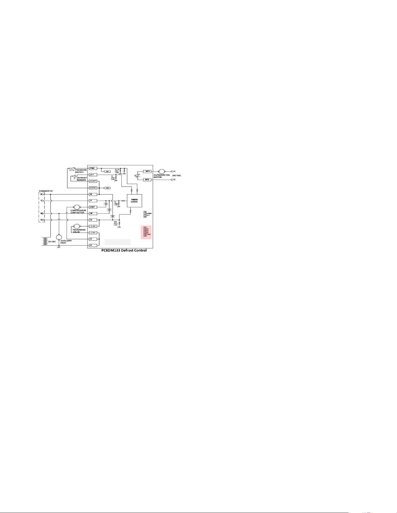
DEFROST CYCLE
Package Heat Pumps
The defrosting of the outdoor coil is jointly controlled by the
defrost control board and the defrost thermostat.
SYSTEM OPERATION
8
Solid State Defrost Control
During operation the power to the circuit board is controlled
by a temperature sensor, which is clamped to a feeder tube
entering the outdoor coil. Defrost timing periods of 30, 60,
or 90 minutes may be selected by setting the circuit board
jumper to 30, 60, or 90 respectively. Accumulation of time
for the timing period selected starts when the sensor closes
(approximately 30°F), and when the room thermostat
calls for heat. At the end of the timing period, the unit’s
defrost cycle will be initiated provided the sensor remains
closed. When the sensor opens (approximately 60°F), the
defrost cycle is terminated and the timing period is reset.
If the defrost cycle is not terminated due to the sensor
temperature, a twelve minute override interrupts the unit’s
defrost period.
FAN OPERATION
Continuous Fan Mode
GPCM3 & A/GPHM3 EEM Equipped Models Only:
If the thermostat calls for continuous fan, the indoor blower
will be energized from the G terminal of the thermostat to
the EEM blower motor.
If a call for heat or cool occurs during a continuous fan call,
the EEM motor will always recognize the call for the highest
speed and ignore the lower speed call.
If the thermostat is not calling for heat or cool, and the
fan switch on the thermostat is returned to the automatic
position, the fan will stop after the programmed 60 second
o delay on units with the EEM motor.
SYSTEM OPERATION
9
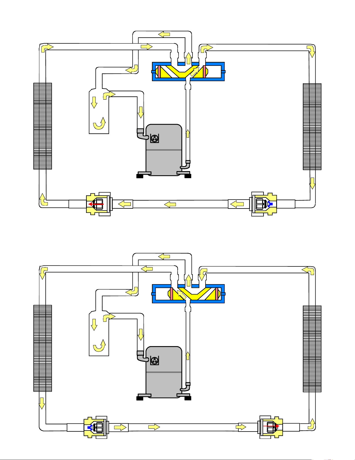
Indoor
Coil
Accumulator
Outdoor
Coil
Reversing Valve
(Energized)
Indoor
Coil
Accumulator
Outdoor
Coil
Reversing Valve
(De-Energized)
Typical Heat Pump System in Cooling
Typical Heat Pump System in Heating
SCHEDULED MAINTENANCE
10
Package units require regularly scheduled maintenance to
preserve high performance standards, prolong the service
life of the equipment, and lessen the chances of costly
failure.
In many instances the owner may be able to perform some
of the maintenance; however, the advantage of a service
contract, which places all maintenance in the hands of a
trained serviceman, should be pointed out to the owner.
WARNING
High Voltage!
Disconnect all power before servicing or
installing. Multiple power sources may be present.
Failure to do so may cause property damage,
personal injury or death.
ONCE A MONTH
1. Inspect the return lters of the evaporator unit and
clean or change if necessary. NOTE: Depending on
operation conditions, it may be necessary to clean or
replace the lters more often. If permanent type lters
are used, they should be washed with warm water
and dried.
2. When operating on the cooling cycle, inspect the
condensate line piping from the evaporator coil. Make
sure the piping is clear for proper condensate ow.
ONCE A YEAR
Qualified Service Personnel Only
1. Clean the indoor and outdoor coils.
2. Clean the cabinet inside and out.
3. Motors are permanently lubricated and do not require
oiling. TO AVOID PREMATURE MOTOR FAILURE,
DO NOT OIL.
4. Manually rotate the outdoor fan and indoor blower to
be sure they run freely.
5. Inspect the control panel wiring, compressor
connections, and all other component wiring to be
sure all connections are tight. Inspect wire insulation
to be certain that it is good.
6. Check the contacts of the compressor contactor. If
they are burned or pitted, replace the contactor.
7. Using a halide or electronic leak detector, check all
piping and etc. for refrigerant leaks.
TEST EQUIPMENT
Proper test equipment for accurate diagnosis is as
essential as regular hand tools.
The following is a must for every service technician and
service shop:
1. Thermocouple type temperature meter - measure dry
bulb temperature.
2. Sling psychrometer - measure relative humidity and
wet bulb temperature.
3. Volt-Ohm Meter - testing continuity, capacitors, motor
windings and voltage.
4. Accurate Leak Detector - testing for refrigerant leaks.
5. High Vacuum Pump - evacuation.
6. Electric Vacuum Gauge, Manifold Gauges and
high vacuum hoses - to measure and obtain proper
vacuum.
7. Accurate Charging Cylinder or Electronic Scale -
measure proper refrigerant charge.
8. Inclined Manometer - measure static pressure and
pressure drop across coils.
Other recording type instruments can be essential in
solving abnormal problems, however, in many instances
they may be rented from local sources.
Proper equipment promotes faster, more ecient service,
and accurate repairs with less call backs.
SCHEDULED MAINTENANCE
11
NOTES:
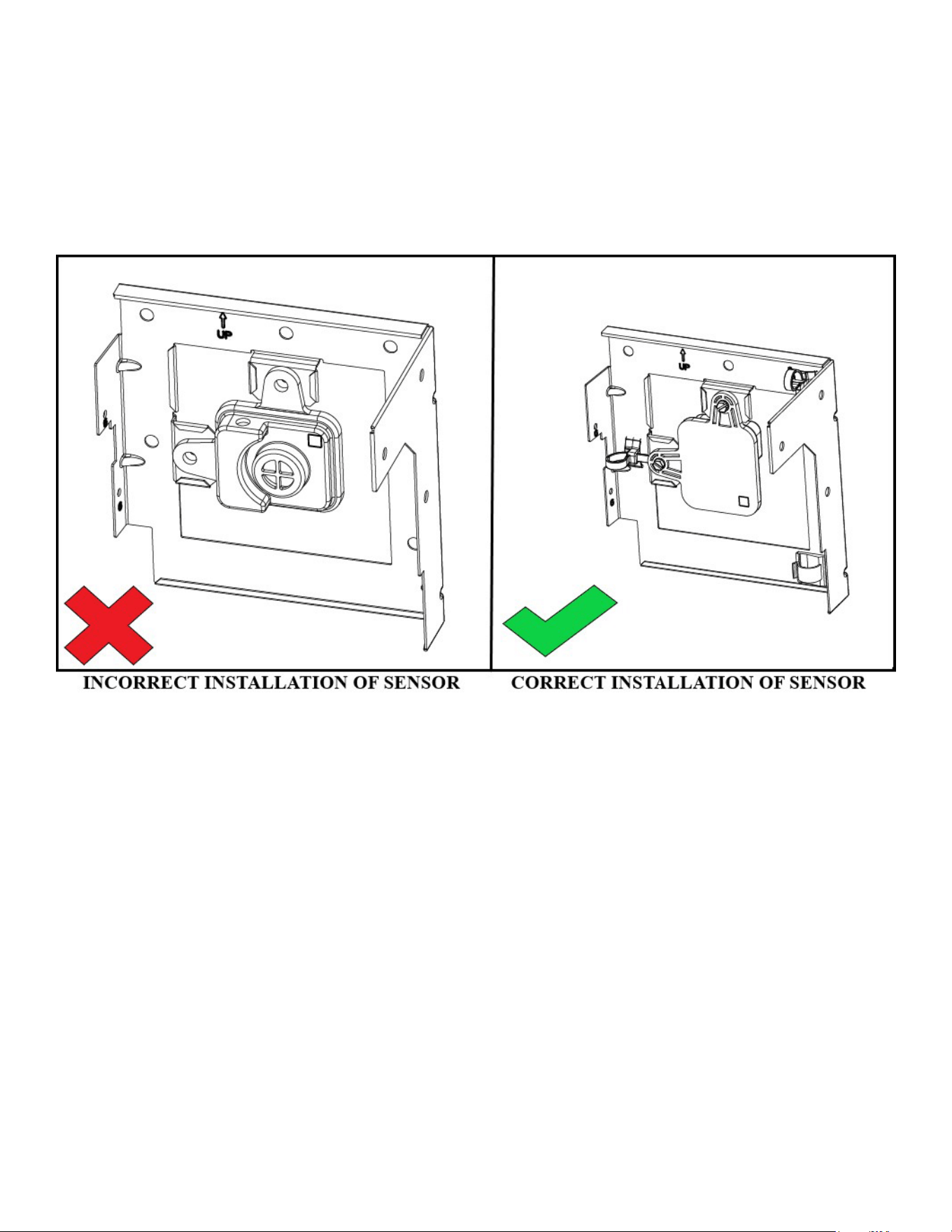
1. For Aluminum indoor coil cleaning, the A2L sensor
must be removed from the unit before applying coil
cleaners to avoid damage and contamination.
2. When replacing the A2L sensor, ensure that the
arrows on the A2L sensor and the sensor bracket are
pointing in the same direction.
SERVICING
12
Checking Voltage
WARNING
High Voltage!
Disconnect all power before servicing or
installing. Multiple power sources may be present.
Failure to do so may cause property damage,
personal injury or death.
Unit Voltage
Rated Voltage
Min. Supply
Voltage
Max. Supply
Voltage
208/230V 197 253
1. Remove doors, control panel cover, etc. from unit
being tested.
With power ON:
WARNING
Line voltage now present.
2. Using a voltmeter, measure the voltage across
terminals L1 and L2 of the contactor.
3. No reading - indicates open wiring, open fuse(s) no
power or etc. from unit to fused disconnect service.
Repair as needed.
4. If incoming voltage is within the range listed in the
chart below, energize the unit.
5. Using a voltmeter, measure the voltage with the unit
starting and operating to determine if voltage is within
the range listed in the chart below.
6. If the voltage falls below the minimum voltage, check
the line wire size. Long runs of undersized wire can
cause low voltage. If the wire size is adequate, notify
the local power company regarding either low or high
voltage.
Checking Wiring
WARNING
High Voltage!
Disconnect all power before servicing or
installing. Multiple power sources may be present.
Failure to do so may cause property damage,
personal injury or death.
1. Check wiring visually for signs of overheating,
damaged insulation and loose connections.
2. Use an ohmmeter to check continuity of any
suspected open wires.
3. If any wires must be replaced, replace with
comparable gauge and insulation thickness.
Checking Thermostat and Wiring
Branch Circuit
Ampacity
15 20 25 30 35 40 45 50
SUPPLY WIRE
LENGTH - FEET
200 6 4 4 4 3 3 2 2
150 8 6 6 4 4 4 3 3
100 10 8 8 6 6 6 4 4
50 14 12 10 10 8 8 6 6
Wiring Table
Thermostat Wiring: The maximum wire length for 18 AWG
thermostat wire is 100 feet.
GPCM3 Thermostat Wiring
Terminal Thermostat
Red R (24V)
Green G (fan)
Yellow Y (Cool)
White W1 (Heat, Aux Heat Stage 1)*
Brown W2 (Heat, Aux Heat Stage 2)*
Blue C (Common)
*Optional eld installed heat connections
*PHM3 Thermostat Wiring
Terminal Thermostat
Red R (24V)
Green G (fan)
Orange O (Rev. Valve)
White W1 (Heat, Aux Heat Stage 1)*
Brown W2 (Heat, Aux Heat Stage 2)*
Yellow Y (Compressor)
Blue C (24V Common)
*Optional eld installed heat connections
Thermostats must be set to energize “G” during cooling.
This is default on most thermostats.
SERVICING
13
*PHM5[24-48]41 Thermostat Wiring
Terminal Thermostat
Red R (24V)
Green G (fan)
Orange O (Rev. Valve)
White W1 (Heat, Aux Heat Stage 1)*
Brown W2 (Heat, Aux Heat Stage 2)*
Purple Y1 (Compressor Stage 1)
Yellow Y2 (Compressor Stage 2)
Blue C (24V Common)
*Optional eld installed heat connections
Thermostats must be set to energize “G” during cooling.
This is default on most thermostats.
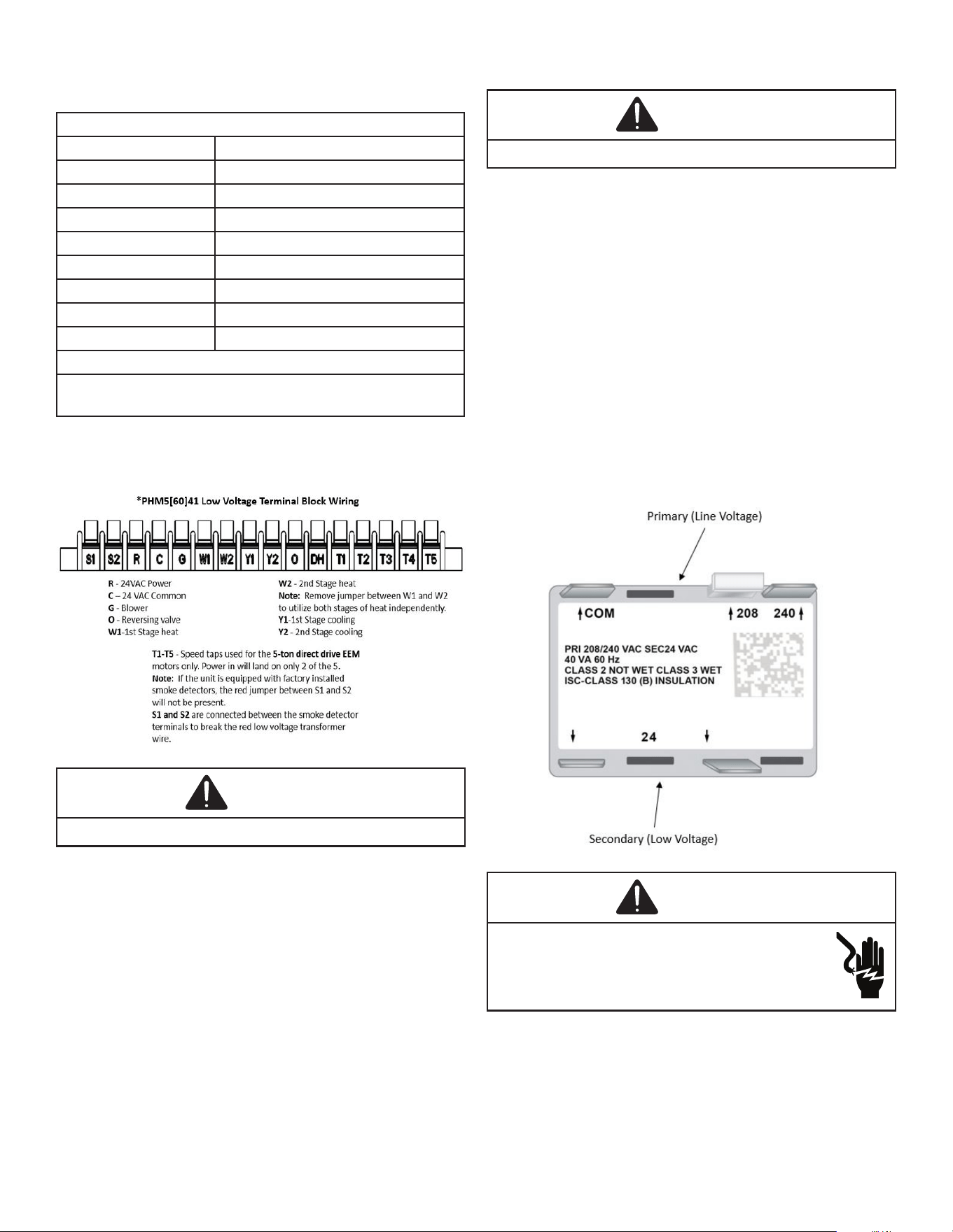
NOTE: &PHM5[60]41 models have a low voltage
terminal block for thermostat connections.
WARNING
Line voltage now present.
With power ON, thermostat calling for cooling:
1. Use a voltmeter to verify 24 volts present at
thermostat wires C and R.
2. If no voltage present, check transformer and
transformer wiring. If 24 volts present, proceed to step
3.
3. Use a voltmeter to check for 24 volts at thermostat
wires C and Y.
4. No voltage indicates trouble in the thermostat, wiring
or external transformer source.
5. Check the continuity of the thermostat and wiring.
Repair or replace as necessary.
Indoor Blower Motor
With power ON:
WARNING
Line voltage now present.
1. Use a voltmeter to verify 24 volts present at
thermostat wires C and R.
2. If no voltage present, check transformer and
transformer wiring. If 24 volts present, proceed to step
3.
3. Set fan selector switch at thermostat to “ON” position.
4. With voltmeter, check for 24 volts at wires C and G.
5. No voltage, indicates the trouble is in the thermostat
or wiring.
6. Check the continuity of the thermostat and wiring.
Repair or replace as necessary.
Checking Transformer and Control Circuit
A step-down transformer (208/240 volt primary to 24 volt
secondary) is provided with each package unit. This allows
ample capacity for use with resistance heaters.
WARNING
High Voltage!
Disconnect all power before servicing or
installing. Multiple power sources may be present.
Failure to do so may cause property damage,
personal injury or death.
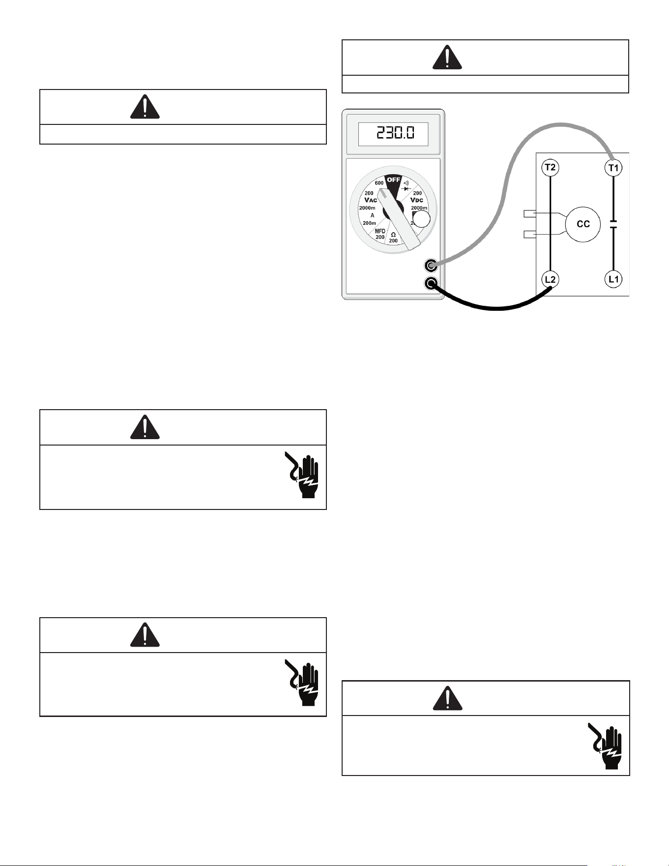
1. Remove control panel cover, or etc., to gain access to
transformer.
SERVICING
14
With power ON:
WARNING
Line voltage now present.
2. Using a voltmeter, check voltage across secondary
voltage side of transformer (R to C).
3. No voltage indicates faulty transformer, bad wiring, or
bad splices.
4. Check transformer primary voltage at incoming line
voltage connections and/or splices.
5. If line voltage is present at the primary voltage side
of the transformer and 24 volts is not present on the
secondary side, then the transformer is inoperative.
Replace.
Checking Contactor and/or Relays
The compressor contactor and other relay holding coils are
wired into the low or line voltage circuits. When the control
circuit is energized, the coil pulls in the normally open
contacts or opens the normally closed contacts. When the
coil is de-energized, springs return the contacts to their
normal position.
WARNING
High Voltage!
Disconnect all power before servicing or
installing. Multiple power sources may be present.
Failure to do so may cause property damage,
personal injury or death.
1. Remove the leads from the holding coil.
2. Using an ohmmeter, test across the coil terminals.
If the coil does not test continuous, replace the relay or
contactor.
Checking Contactor Contacts
WARNING
High Voltage!
Disconnect all power before servicing or
installing. Multiple power sources may be present.
Failure to do so may cause property damage,
personal injury or death.
Single Phase
1. Disconnect the wire leads from the terminal (T) side of
the contactor.
2. With power ON, energize the contactor.
WARNING
Line voltage now present.
Testing Compressor Contactor
(Single Phase)
3. Using a voltmeter, test across terminals.
A. L1 - L2 - No voltage. Check breaker or fuses on
main power supply. If voltage present, proceed to
step B.
B. T1 to T2 - Meter should read the same as L1 to L2
in step A. If voltage readings are not the same as
step A, replace contactor.
Checking Low Pressure Control
(Heat Pump Models)
The low pressure control senses the pressure in the
suction line and will open its contacts on a drop in
pressure. The low pressure control will automatically reset
itself with a rise in pressure.
The low pressure control is designed to cut-out (open) at
approximately 22 PSIG. It will automatically cut-in (close) at
approximately 50 PSIG.
Test for continuity using a VOM and if not as above,
replace the control.
Checking High Pressure Control
WARNING
High Voltage!
Disconnect all power before servicing or
installing. Multiple power sources may be present.
Failure to do so may cause property damage,
personal injury or death.
The high pressure control capillary senses the pressure in
the liquid or discharge line. If abnormally high condensing
SERVICING
15
pressures develop, the contacts of the control open,
breaking the control circuit before the compressor motor
overloads. This control is automatically reset.
1. Using an ohmmeter, check across terminals of high
pressure control, with wire removed. If not continuous,
the contacts are open.
If the high-pressure switch needs to be replaced, please
follow the instructions below.
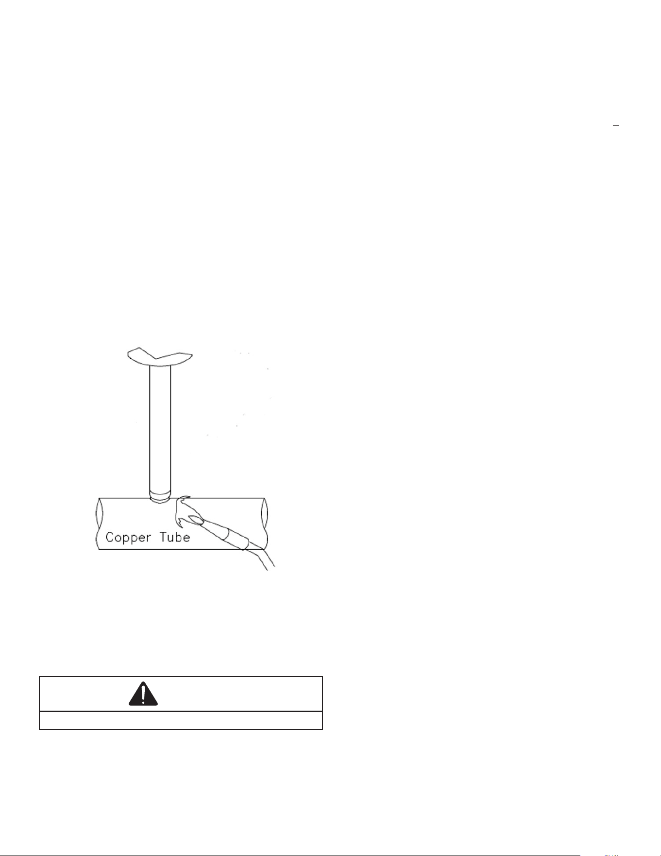
The copper tube should absorb all the heating, while the
high-pressure switch is heated solely by conduction. To
prevent overheating, the torch tip should be kept away from
the switch, ensuring the inner cone of the ame does not
make contact. Heating should be achieved using the outer
ame envelope, and the level of the brazing ame should
be kept low. During manual torch brazing, the torch should
remain on the copper tubing and be kept in motion to avoid
localized overheating.
Brazing High Pressure Switch
TORCH: A multi-tip torch is recommended, making heating
faster and more uniform than with a single ame.
2. Attach a gauge to the dill valve port on the base valve.
With power ON:
WARNING
Line voltage now present.
3. Start the system and place a piece of cardboard in
front of the condenser coil, raising the condensing
pressure.
4. Check pressure at which the high pressure control
cuts-out.
If it cuts-out at 660 PSIG ± 10 PSIG, it is operating normally
(See causes for high head pressure in Service Problem
Analysis Guide). If it cuts out below this pressure range,
replace the control. The control should reset at 420 PSIG +
25 PSIG.
Checking Internal Overload
The Internal Overload prevents the compressor windings
from overheating. Reacts to both current and temperature
Cuts out 302°F. Cuts in between 146 and 176°F
1. Using an ohmmeter, test continuity between terminals,
If either winding test continuous, Internal overload
open.
2. Allow time for the compressor to cool, and overload to
close and retest.
Checking Capacitor
Capacitor, Run
A run capacitor is wired across the auxiliary and main
windings of a single phase permanent split capacitor
motor. The capacitors primary function is to reduce the line
current while greatly improving the torque characteristics
of a motor. This is accomplished by using the 90° phase
relationship between the capacitor current and voltage
in conjunction with the motor windings so that the motor
will give two phase operation when connected to a single
phase circuit. The capacitor also reduces the line current to
the motor by improving the power factor.
Capacitor, Start
Scroll Compressor Models
Hard start components are not required on Scroll
compressor equipped units due to a non-replaceable check
valve located in the discharge line of the compressor.
However hard start kits are available and may improve low
voltage starting characteristics.
This check valve closes o high side pressure to the
compressor after shut down allowing equalization through
the scroll anks. Equalization requires only about one or
two seconds during which time the compressor may turn
backwards.
Your unit comes with a 180-second anti-short cycle
to prevent the compressor from starting and running
backwards.
Models Equipped With A Hard Start Device
A start capacitor is wired in parallel with the run capacitor
to increase the starting torque. The start capacitor is of the
electrolytic type, rather than metallized polypropylene as
used in the run capacitor.
SERVICING
16
A switching device must be wired in series with the
capacitor to remove it from the electrical circuit after the
compressor starts to run. Not removing the start capacitor
will overheat the capacitor and burn out the compressor
windings.
These capacitors have a 15,000 ohm, 2 watt resistor
wired across its terminals. The object of the resistor
is to discharge the capacitor under certain operating
conditions, rather than having it discharge across the
closing of the contacts within the switching device such as
the Start Relay, and to reduce the chance of shock to the
servicer. See the Servicing Section for specic information
concerning capacitors.
Relay, Start
A potential or voltage type relay is used to take the start
capacitor out of the circuit once the motor comes up to
speed. This type of relay is position sensitive. The normally
closed contacts are wired in series with the start capacitor
and the relay holding coil is wired parallel with the start
winding. As the motor starts and comes up to speed, the
increase in voltage across the start winding will energize
the start relay holding coil and open the contacts to the
start capacitor.
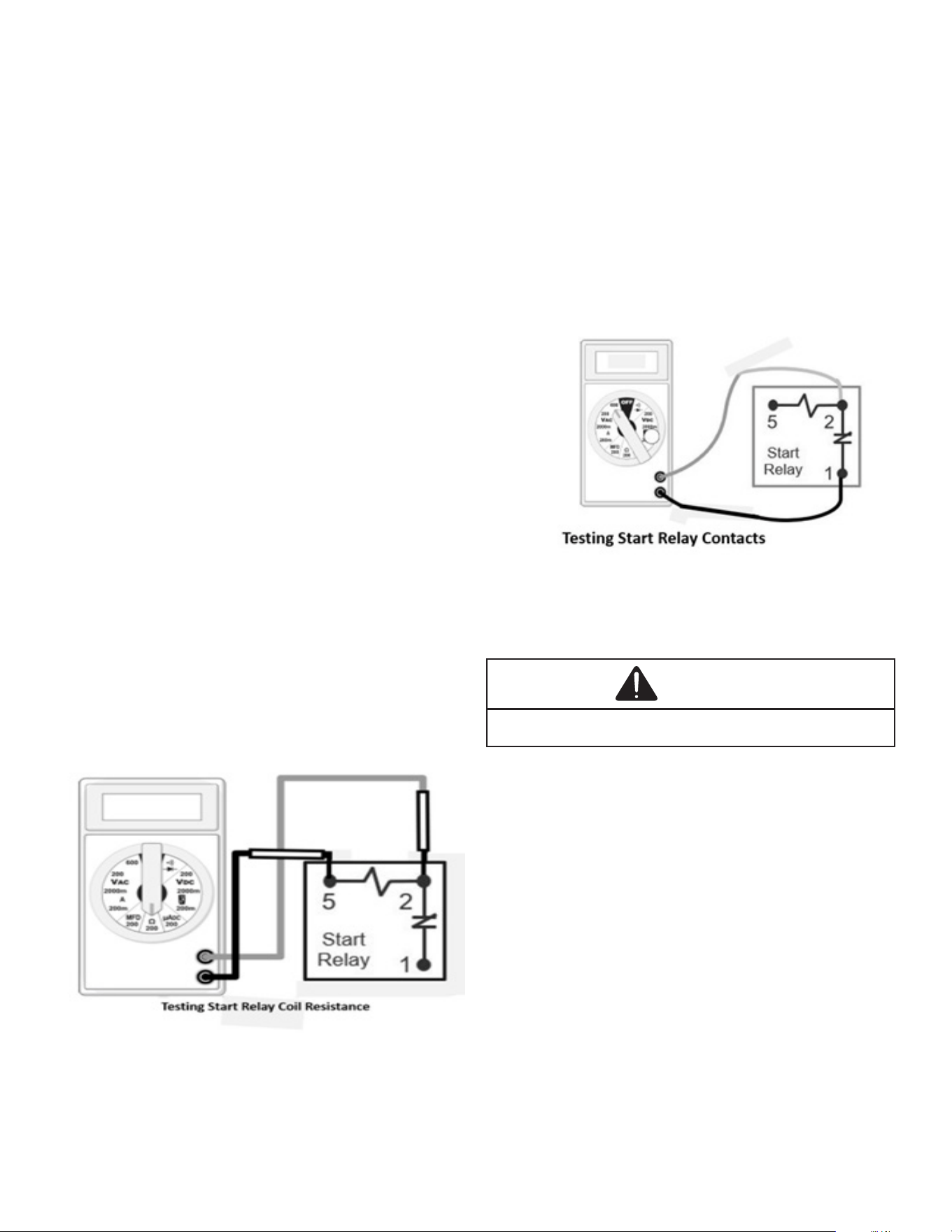
Testing Start Relay Kits
Testing Coil Relay
1. Disconnect power to unit.
2. Disconnect all wiring.
3. Measure the resistance of the coil between terminals
2 & 5.
4. If the coil reads open or shorted, replace the relay.
Testing Contacts Resistance
1. Disconnect power to unit.
2. Disconnect all wiring to the start relay.
3. Measure the resistance of the contacts between
terminals 1 & 2.
4. If the contacts read open, replace the relay.
Testing Contacts Voltage
1. With power on, provide a call for cool to energize the
compressor.
2. With the compressor running, use a voltmeter to
measure the voltage between terminals 1 & 2 voltage
reading of zero indicates that the relay’s contacts are
stuck, replace the relay.
Two quick ways to test a capacitor are a resistance and a
capacitance check.
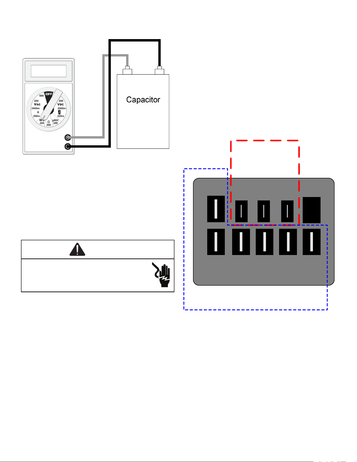
Capacitance Check (MFD)
WARNING
Discharge capacitor through a 20 to 30 OHM resistor before
handling.
1. Turn Power o to Unit.
2. Discharge capacitor through a 20Ω - 30Ω resistor.
3. Remove wires from capacitor.
4. Use multi-meter check micro-farads (MFD) of the
capacitor.
5. Place leads from C – HERM.
6. Place leads from C – FAN.
7. Compare to capacitor rating label.
If the reading is within the tolerance listed on rating label
the capacitor is good.
If the reading is lower, the capacitor is bad and must be
replaced.
SERVICING
17
.
Testing Capacitance
Checking Fan And Blower Motor Windings
(PSC Motors)
The auto reset fan motor overload is designed to protect
the motor against high temperature and high amperage
conditions by breaking the common circuit within the motor,
similar to the compressor internal overload. However, heat
generated within the motor is faster to dissipate than the
compressor, allow at least 45 minutes for the overload to
reset, then retest.
WARNING
High Voltage!
Disconnect all power before servicing or
installing. Multiple power sources may be present.
Failure to do so may cause property damage,
personal injury or death.
1. Remove the motor leads from its respective
connection points and capacitor (if applicable).
2. Check the continuity between each of the motor leads.
3. Touch one probe of the ohmmeter to the motor frame
(ground) and the other probe in turn to each lead.
If the windings do not test continuous or a reading is
obtained from lead to ground, replace the motor.
Checking EEM Motors
The EEM Motor is a one piece, fully encapsulated, 3 phase
brushless DC (single phase AC input) motor with ball
bearing construction. The EEM features an integral control
module.
NOTE: The GE TECMate will not operate the currently
used EEM motor.
1. Using a voltmeter, check for 230 volts to the motor
connections L and N. If 230 volts is present, proceed
to step 2. If 230 volts is not present, check the line
voltage circuit to the motor.
2. Using a voltmeter, check for 24 volts from terminal C
to either terminal 1, 2, 3, 4 or 5, depending on which
tap is being used, at the motor. If voltage is present,
proceed to step 3. If no voltage, check 24 volt circuit
to motor.
3. If voltage was present in steps 1 and 2, the motor has
failed and will need to be replaced.
NOTE: When replacing motor, ensure the belly band is
between the vents on the motor and the wiring has the
proper drip loop to prevent condensate from entering
the motor.
C
L
G N
1 2 3
4
5
High Voltage
Connections
3/16"
Low Voltage Connections
1/4”
EEM Motor Connections
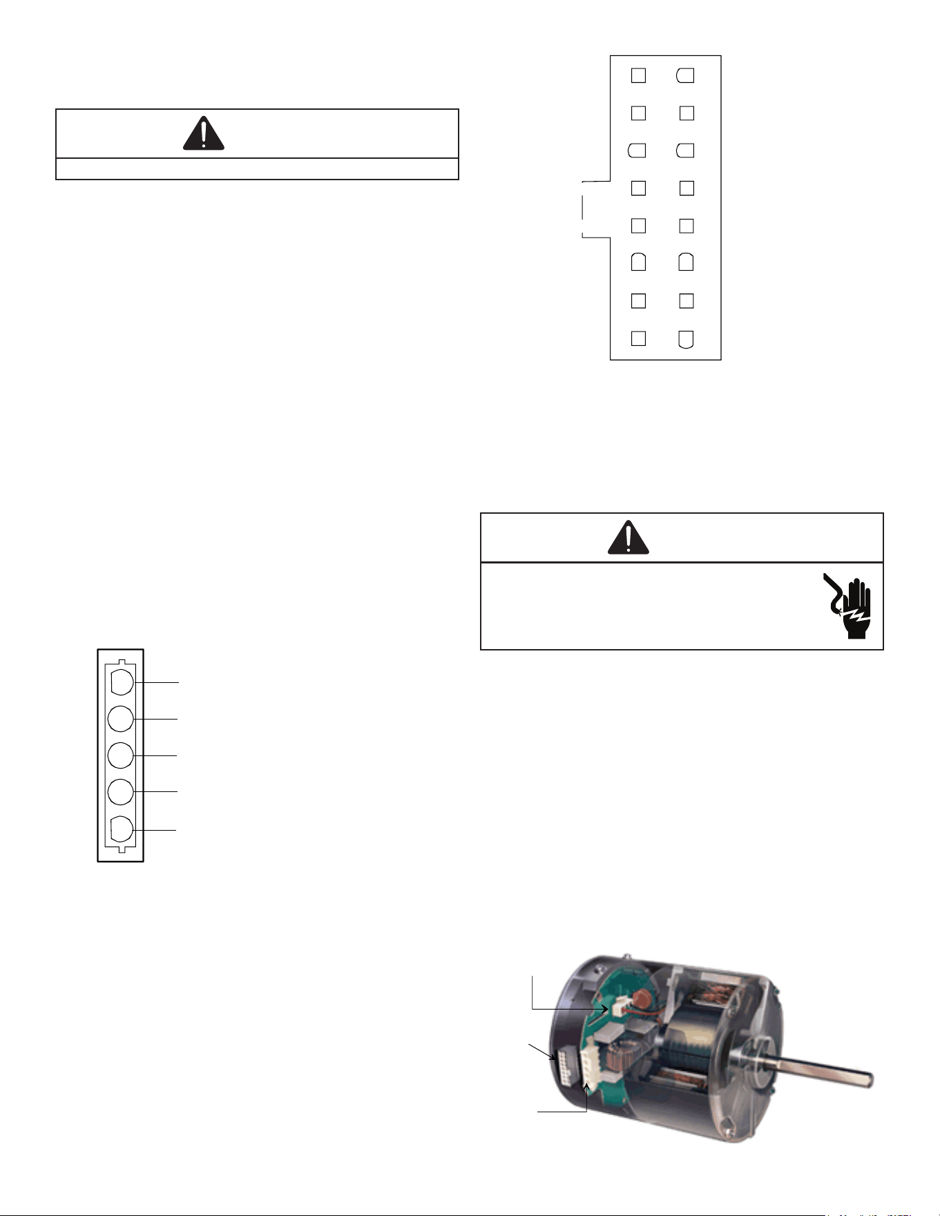
Checking ECM Motors
An ECM is an Electronically Commutated Motor which
oers many signicant advantages over PSC motors.
The ECM has near zero rotor loss, synchronous machine
operation, variable speed, low noise, and programmable
air ow. Because of the sophisticated electronics within
the ECM motor, some technicians are intimated by the
ECM motor; however, these fears are unfounded. GE/
Regal Beloit oers two ECM motor testers, and with a VOM
meter, one can easily perform basic troubleshooting on
ECM motors. An ECM motor requires power (line voltage)
and a signal (24 volts) to operate. The ECM motor stator
contains permanent magnet. As a result, the shaft feels
“rough” when turned by hand. This is a characteristic of the
motor, not an indication of defective bearings.
SERVICING
18
WARNING
Line voltage now present.
1. Disconnect the 5-pin connector from the motor.
2. Using a volt meter, check for line voltage at terminals
#4 & #5 at the power connector. If no voltage is
present:
3. Check the unit for incoming power.
4. Check the control board.
5. If line voltage is present, reinsert the 5-pin connector
and remove the 16-pin connector.
6. Check for signal (24 volts) at the transformer.
7. Check for signal (24 volts) from the thermostat to the
“G” terminal at the 16-pin connector.
8. Using an ohmmeter, check for continuity from the #1
& #3 (common pins) to the transformer neutral or “C”
thermostat terminal. If you do not have continuity, the
motor may function erratically. Trace the common
circuits, locate and repair the open neutral.
9. Set the thermostat to “Fan-On”. Using a voltmeter,
check for 24 volts between pin # 15 (G) and common.
10. Disconnect power to compressor. Set thermostat to
call for cooling. Using a voltmeter, check for 24 volts
at pin # 6 and or #14.
11. Set the thermostat to a call for heating. Using a
voltmeter, check for 24 volts at pin #2 and/or #11.
1
2
3
4
5
Lines 1 and 2 will be connected
for 12OVAC Power Connector
applications only
Gnd
AC Line Connection
AC Line Connection
}
11
1 9
2
3
4
5
6
7
8 16
15
14
13
12
10
OUT - OUT +
ADJUST +/-
G (FAN)
Y1 Y/Y2
COOL
EM Ht/W2
DELAY
24 Vac (R)
COMMON2
HEAT
W/W1
BK/PWM (SPEED)
COMMON1 O (REV VALVE)
16-PIN ECM HARNESS CONNECTOR
If you do not read voltage and continuity as described, the
problem is in the control or interface board, but not the
motor. If you register voltage as described, the ECM power
head is defective and must be replaced.
Checking ECM Motor Windings
WARNING
High Voltage!
Disconnect all power before servicing or
installing. Multiple power sources may be present.
Failure to do so may cause property damage,
personal injury or death.
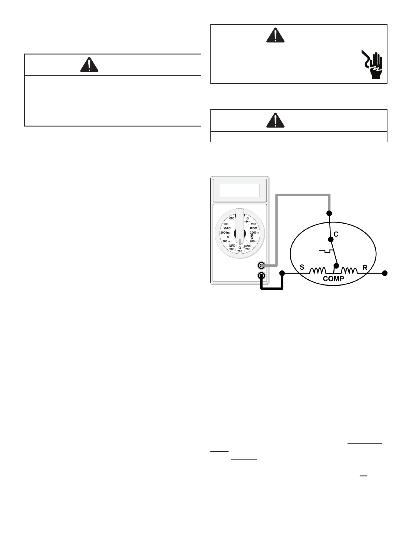
1. Disconnect the 5-pin and the 16-pin connectors from
the ECM power head.
2. Remove the 2 screws securing the ECM power head
and separate it from the motor.
3. Disconnect the 3-pin motor connector from the power
head and lay it aside.
4. Using an ohmmeter, check the motor windings for
continuity to ground (pins to motor shell). If the
ohmmeter indicates continuity to ground, the motor is
defective and must be replaced.
5. Using an ohmmeter, check the windings for continuity
(pin to pin). If no continuity is indicated, the thermal
limit (over load) device may be open. Allow motor to
cool and retest.
16-pin
connector
5-pin
connector
3-pin motor
connector
SERVICING
19
Checking Compressor
WARNING
Hermetic compressor electrical terminal venting can
be dangerous. When insulating material which supports
a hermetic compressor or electrical terminal suddenly
disintegrates due to physical abuse or as a result of an
electrical short between the terminal and the compressor
housing, the terminal may be expelled, venting the vapor and
liquid contents of the compressor housing and system.
If the compressor terminal PROTECTIVE COVER and
gasket (if required) are not properly in place and secured,
there is a remote possibility if a terminal vents, that the
vaporous and liquid discharge can be ignited, spouting
ames several feet, causing potentially severe or fatal
injury to anyone in its path.
This discharge can be ignited external to the compressor
if the terminal cover is not properly in place and if the
discharge impinges on a sucient heat source.
Ignition of the discharge can also occur at the venting
terminal or inside the compressor, if there is sucient
contaminant air present in the system and an electrical arc
occurs as the terminal vents.
Ignition cannot occur at the venting terminal without the
presence of contaminant air, and cannot occur externally
from the venting terminal without the presence of an
external ignition source.
Therefore, proper evacuation of a hermetic system is
essential at the time of manufacture and during servicing.
To reduce the possibility of external ignition, all open
ame, electrical power, and other heat sources should be
extinguished or turned o prior to servicing a system.
If the following test indicates shorted, grounded or open
windings, see procedure for the next steps to be taken.
Resistance Test
Each compressor is equipped with an internal overload.
The line break internal overload senses both motor
amperage and winding temperature. High motor
temperature or amperage heats the disc causing it to open,
breaking the common circuit within the compressor on
single phase units.
Heat generated within the compressor shell, usually due to
recycling of the motor, high amperage or insucient gas to
cool the motor, is slow to dissipate. Allow at least three to
four hours for it to cool and reset, then retest.
WARNING
High Voltage!
Disconnect all power before servicing or
installing. Multiple power sources may be present.
Failure to do so may cause property damage,
personal injury or death.
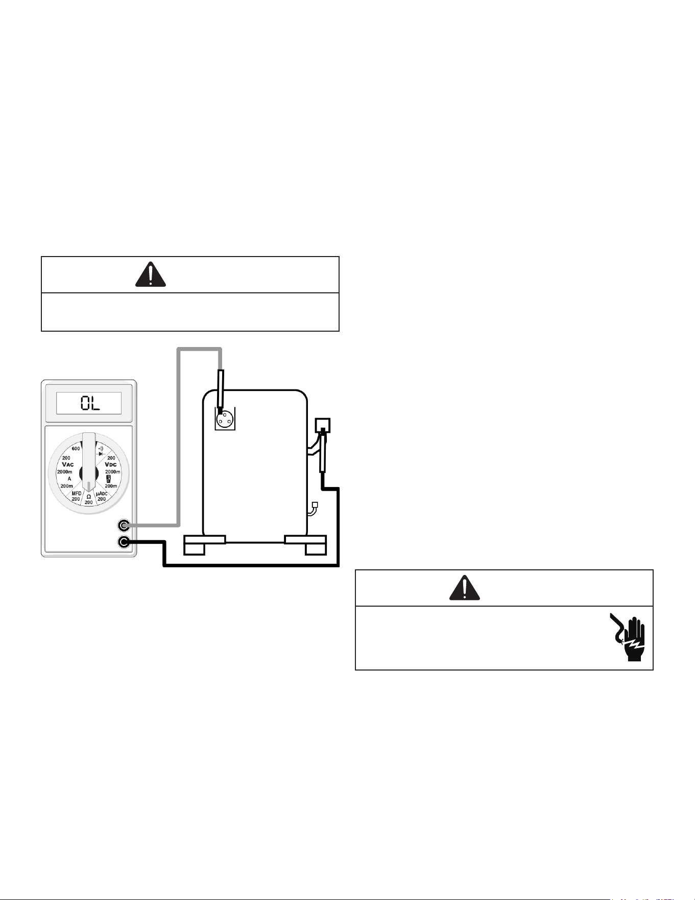
1. Remove the leads from the compressor terminals.
WARNING
See warnings before removing compressor terminal cover.
2. Using an ohmmeter, test continuity between terminals
S-R, C-R, and C-S.
Testing Compressor Windings
If either winding does not test continuous, replace the
compressor.
NOTE: If an open compressor is indicated, allow ample
time for the internal overload to reset before replacing
compressor.
Ground Test
If fuse, circuit breaker, ground fault protective device, etc.
has tripped, this is a strong indication that an electrical
problem exists and must be found and corrected. The
circuit protective device rating must be checked and its
maximum rating should coincide with that marked on the
equipment nameplate.
With the terminal protective cover in place, it is acceptable
to replace the fuse or reset the circuit breaker ONE TIME
ONLY to see if it was just a nuisance opening. If it opens
again, DO NOT continue to reset.
Disconnect all power to unit, making sure that all
power legs are open.
SERVICING
20
1. Carefully remove the compressor terminal protective
cover and inspect for loose leads or insulation breaks
in the lead wires.
2. Disconnect the three leads going to the compressor
terminals at the compressor or nearest point to the
compressor.
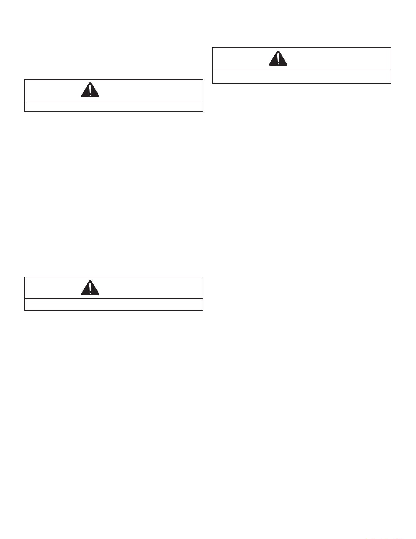
3. Check for a ground separately between each of the
three terminals and ground (such as an unpainted
tube on the compressor). If there is any reading of
continuity to ground on the meter, the compressor
should be considered defective.
4. If ground is indicated, replace the compressor.
WARNING
Damage can occur to the glass embedded terminals if the
leads are not properly removed. This can result in terminal
and hot oil discharging.
Compressor Ground Test
Unloader Test Procedure
(2 Stage Compressors Only)
A nominal 24-volt direct current coil activates the
compressor internal unloader solenoid. The input control
circuit voltage must be 18 to 28 volt ac (remove). The
coil power requirement is 5 VA. The external electrical
connection is made with a molded plug assembly. This plug
contains a full wave rectier to supply direct current to the
unloader coil. The measured DC voltage at the connectors
in the plug should be 15 to 27 volt dc.
Unloader Test Procedure
If it is suspected that the unloader is not working, the
following methods may be used to verify operation.
1. Operate the system and measure compressor
amperage. Cycle the unloader ON and OFF at 10
second intervals. The compressor amperage should
increase when switching from part-load to full-load
and decrease when switching from full-load to part-
load. The percent change depends on the operating
conditions and voltage, but should be at least 25
percent.
2. If step one does not give the expected results, shut
unit o. Apply 18 to 28 volt ac to the unloader molded
plug leads and listen for a click as the solenoid pulls
in. Remove power and listen for another click as the
unloader returns to its original position.
3. If clicks can’t be heard, shut o power to the unit
and remove the control circuit molded plug from the
compressor and measure the unloader coil resistance
(connections on the compressor). The solenoid coil
should have continuity and not be grounded or have
innite resistance. If the coil resistance is innite, zero,
or grounded, the compressor must be replaced.
4. Next check the molded plug.
A. Voltage check: Apply control voltage to the plug
wires (18 to 28 volt ac). The measured dc voltage
at the female connectors in the plug should be
around 15 to 27 vdc.
B. Resistance check: Measure the resistance
from the end of one molded plug lead to either
of the two female connectors in the plug. One of
the connectors should read close to zero ohms
while the other should read innity. Repeat with
other wire. The same female connector as before
should read zero while the other connector again
reads innity. Reverse polarity on the ohmmeter
leads and repeat. The female connector that read
innity previously should now read close to zero
ohms.
C. Replace plug if either of these test methods
doesn’t show the desired results.
Operation Test
If the voltage, capacitor, overload and motor winding test
fail to show the cause for failure.
WARNING
High Voltage!
Disconnect all power before servicing or
installing. Multiple power sources may be present.
Failure to do so may cause property damage,
personal injury or death.
1. Remove unit wiring from disconnect switch and wire a
test cord to the disconnect switch.
NOTE: The wire size of the test cord must equal the
line wire size and the fuse must be of the proper size
and type.
2. With the protective terminal cover in place, use the
three leads to the compressor terminals that were
disconnected at the nearest point to the compressor
and connect the common, start and run clips to the
respective leads.
SERVICING
21
3. Connect good capacitors of the right MFD and voltage
rating into the circuit as shown.
4. With power ON, close the switch.
WARNING
Line voltage now present.
A. If the compressor starts and continues to run,
the cause for failure is somewhere else in the
system.
B. If the compressor fails to start - replace.
Locked Rotor Test
If fuse, circuit breaker, ground fault protective device, etc.
has tripped, this is a strong indication that an electrical
problem exists and must be found and corrected. The
circuit protective device rating must be checked and its
maximum rating should coincide with that marked on the
equipment nameplate.
Before checking for locked rotor, the compressor terminals
should be checked for open windings (see Resistance Test)
and the run capacitor and start capacitor (if used) should
be checked thoroughly (see Checking Capacitor).
With power ON:
WARNING
Line voltage now present.
1. Check the serial data plate for the compressor locked
rotor amps (LRA) rating.
2. Using an ampmeter, measure the amperage reading
for the run and common wires to the compressor.
Since the compressor motor overload will likely
trip soon after drawing locked rotor amps, this
measurement should be taken as soon as the
compressor starts.
3. If the amperage reading roughly equals the
compressor LRA rating and all other checks have
been completed, locked rotor amps has been veried.
Testing Crankcase Heater
NOTE: Not all compressors use crankcase heaters.
The crankcase heater must be energized a minimum of
four (4) hours before the condensing unit is operated.
Crankcase heaters are used to prevent migration or
accumulation of refrigerant in the compressor crankcase
during the o cycles and prevents liquid slugging or oil
pumping on start up.
A crankcase heater will not prevent compressor damage
due to a oodback or over charge condition.
WARNING
Disconnect ALL power before servicing.
1. Disconnect the heater lead in wires.
2. Using an ohmmeter, check heater continuity - should
test continuous. If not, replace.
Checking Crankcase Heater Thermostat
NOTE: Not all models with crankcase heaters will have
a crankcase heater thermostat.
1. Install a thermocouple type temperature test lead on
the discharge line adjacent to the crankcase heater
thermostat.
2. Check the temperature at which the control closes its
contacts by lowering the temperature of the control.
The crankcase heater thermostat should close at 67°F
± 5°F.
3. Check the temperature at which the control opens its
contacts by raising the temperature of the control. The
crankcase heater thermostat should open at 85°F ±
5°F.
4. If not as above, replace control.
Checking Reversing Valve And Solenoid
Reversing valve used in heat pumps could potentially leak
internally. Discharge gases can leak into the suction inside
the valve. Compound gages will give the same symptoms
as bad compressor valves or broken scroll anks. The
temperature between true suction and the suction line after
the valve should not be greater than 4 degrees. NOTE: The
center tube is always the suction line and should be cold.
Troubleshooting the Reversing Valve for
Electrical Failure
1. Place unit into the cooling mode. Test for 24 volts at
the solenoid. If there is no voltage present at coil,
check the control voltage.
2. If voltage is present, loosen the nut on the top of
the coil. Remove the coil, there should be slight
resistance.
3. If the slight resistance is felt, remove the coil. As you
remove the coil listen carefully, an audible click should
be detected. The clicking is due to the movement
of the pilot valve plunger. The absence of a clicking
sound indicates the plunger is stuck.
Troubleshooting Mechanical Failures on a
Reversing Valve by Pressure
1. Troubleshooting the reversing valve can be done by
pressure and touch.
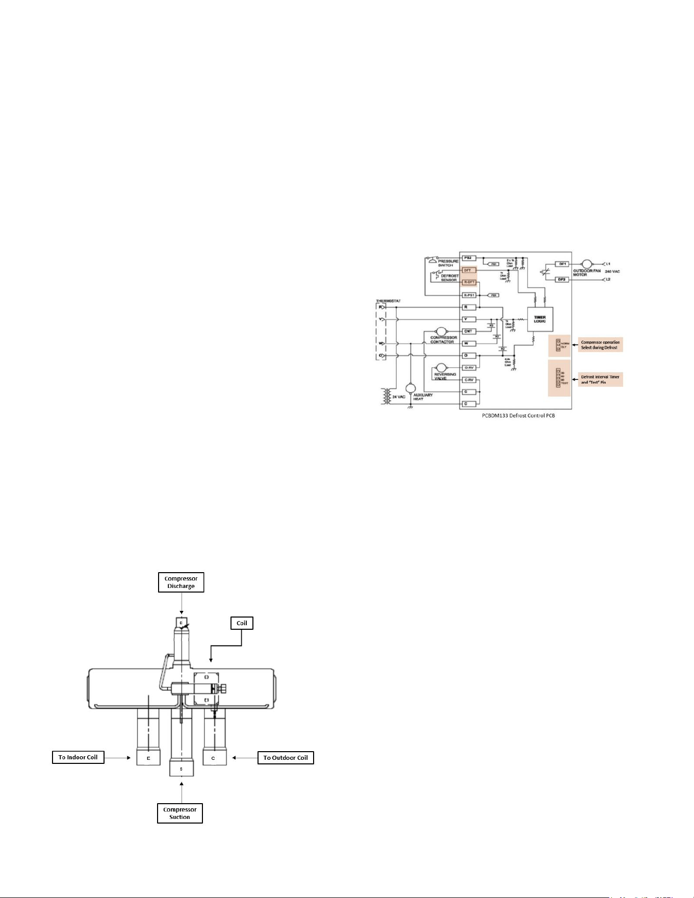
SERVICING
22
2. Raise the head pressure. In the cooling mode block
the fan exhaust. Once head pressure has been
raised, cycle between cooling and heating and see if
the piston can be freed.
Troubleshooting Mechanical Failures on a
Reversing Valve by Temperature
1. When operating properly the valve contains refrigerant
gases at certain temperatures.
2. The discharge line should be the same temperature
after the valves discharge line.
3. The true suction should be the same as the suction
line after the valve. If there is a 4-degree dierence,
valve is leaking
When stuck in the mid-position, part of the discharge gas
from the compressor is directed back to the suction side,
resulting in excessively high suction pressure. An increase
in the suction line temperature through the reversing
valve can also be measured. Check operation of the valve
by starting the system and switching the operation from
COOLING to HEATING cycle.
If the valve fails to change its position, test the voltage
(24V) at the valve coil terminals, while the system is on the
COOLING cycle.
If voltage is registered at the coil, tap the valve body lightly
while switching the system from HEATING to COOLING,
etc. If this fails to cause the valve to switch positions,
remove the coil connector cap and test the continuity of
the reversing valve solenoid coil. If the coil does not test
continuous - replace it. If the coil test continuous and 24
volts is present at the coil terminals, the valve is inoperative
- replace it.
Testing Defrost Control
NOTE: PCBDM133 defrost control has a three (3)
minute compressor o cycle delay.
NOTE: The PCBDM133 defrost control is shipped from
the factory with the compressor delay option selected.
This will de-energize the compressor contactor for 30
seconds on defrost initiation and defrost termination.
If the jumper is set to Normal, the compressor will
continue to run during defrost initiation and defrost
termination. The control will also ignore the low
pressure switch connected to R-PS1 and PS2 for 5
minutes upon defrost initiation and 5 minutes after
defrost termination.
To check the defrost control for proper sequencing,
proceed as follows: With power ON; unit not running.
1. Jumper defrost thermostat by placing a jumper wire
across the terminals “DFT” and “R”/” R-DFT” at
defrost control board.
2. Remove jumper from timer pins and jump across test
pins on defrost control board. NOTE: Do not use
screwdriver or eld supplied jumper to test the
control.
3. Set thermostat to call for heating. System should go
into defrost within 21 seconds.
4. Immediately remove jumper from test pins.
5. Using VOM check for voltage across terminals “C &
O”. Meter should read 24 volts.
6. Using VOM check for voltage across fan terminals
DF1 and DF2 on the board. You should read line
voltage (208-230 VAC) indicating the relay is open in
the defrost mode.
7. Using VOM check for voltage across “W”/”W2” & “C”
terminals on the board. You should read 24 volts.
8. If not as above, replace control board.
9. Set thermostat to o position and disconnect power.
Remove jumper from defrost thermostat and replace
timer jumper to the desired defrost time.
NOTE: Remove jumper across defrost thermostat
before returning system to service.
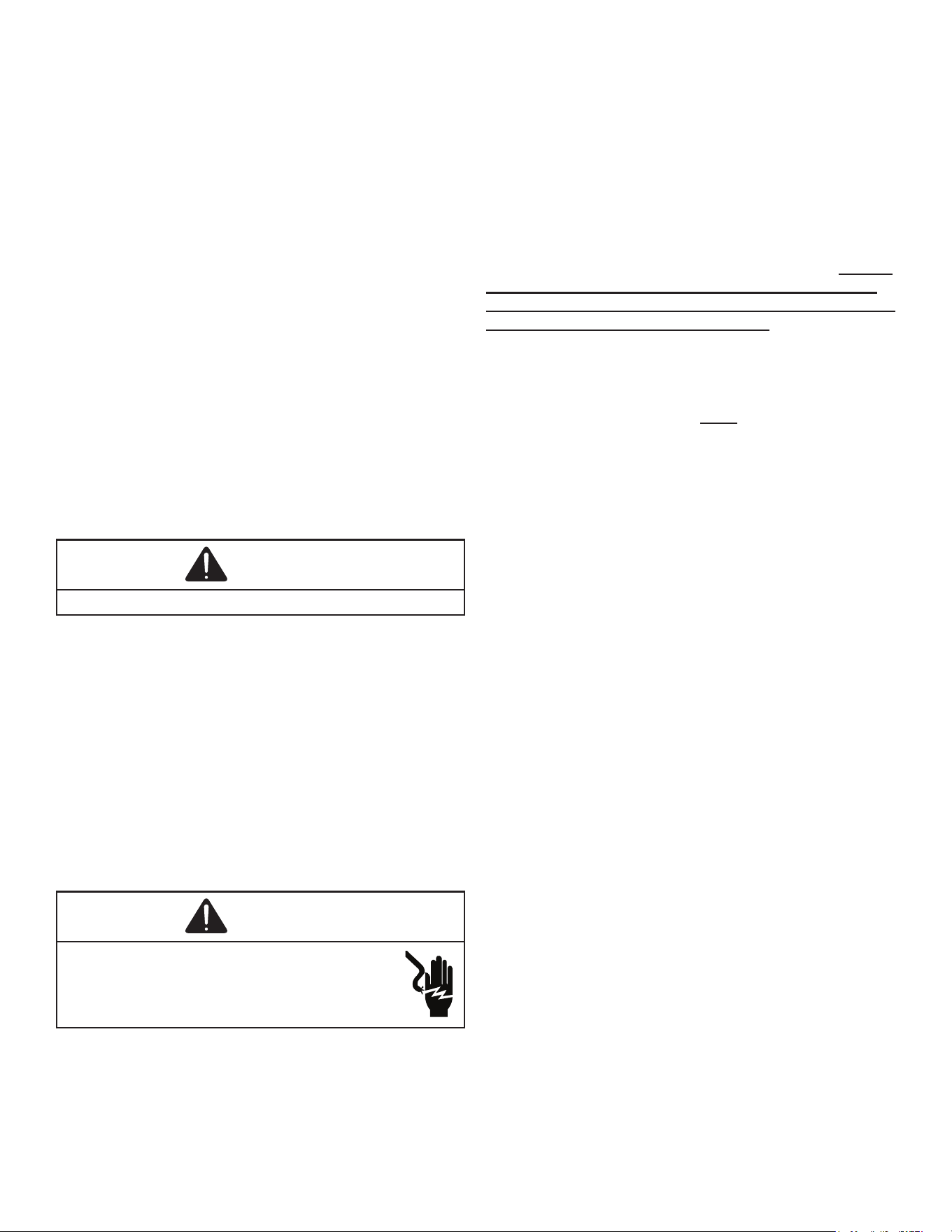
SERVICING
23
Testing Defrost Thermostat
1. Install a thermocouple type temperature test lead on
the tube adjacent to the defrost control. Insulate the
lead point of contact.
2. Check the temperature at which the control closes its
contacts by lowering the temperature of the control.
The defrost control should close at approximately
30°F.
3. Check the temperature at which the control opens its
contacts by raising the temperature of the control. The
defrost control should open at approximately 60°F.
4. If not as above, replace control.
Checking Heater Limit Control(s)
(Optional Electric Heaters)
Each individual heater element is protected with an
automatic rest limit control connected in series with each
element to prevent overheating of components in case
of low airow. This limit control will open its circuit at
approximately 150°F. to 160°F and close at approximately
110°F.
WARNING
Disconnect ALL power before servicing.
1. Remove the wiring from the control terminals.
2. Using an ohmmeter test for continuity across the
normally closed contacts. No reading indicates the
control is open - replace if necessary. Make sure the
limits are cool before testing.
IF FOUND OPEN - REPLACE - DO NOT WIRE AROUND.
Checking Heater Elements
Optional electric heaters may be added, in the quantities
shown in the spec sheet for each model unit, to provide
electric resistance heating. Under no condition shall more
heaters than the quantity shown be installed.
WARNING
High Voltage!
Disconnect all power before servicing or
installing. Multiple power sources may be present.
Failure to do so may cause property damage,
personal injury or death.
1. Disassemble and remove the heating element(s).
2. Visually inspect the heater assembly for any breaks in
the wire or broken insulators.
3. Using an ohmmeter, test the element for continuity -
no reading indicates the element is open. Replace as
necessary.
Refrigeration Repair Practice
DANGER: Always remove the refrigerant charge in a
proper manner before applying heat to the system.
These models use the FasTest Access Fitting System,
with a saddle that is either soldered to the suction and
liquid lines or is fastened with a locking nut to the access
tting box (core) and then screwed into the saddle. Do not
remove the core from the saddle until the refrigerant
charge has been removed. Failure to do so could result
in property damage or personal injury.
When installing a new core or reinstalling the core after
removal, it is very important to note that before inserting
the core into the saddle, the core and saddle must be
free of debris and the “O” Ring must have a thin coating
of refrigerant oil applied to it. The oil is to prevent the “O”
Ring from being deformed when the core is tightened
completely. The core should be torqued to 8 ft. lb.
When repairing the refrigeration system:
1. Never open a system that is under vacuum. Air and
moisture will be drawn in.
2. Plug or cap all openings.
3. Remove all burrs and clean the brazing surfaces of
the tubing with sand cloth or paper. Brazing materials
do not ow well on oxidized or oily surfaces.
4. Clean the inside of all new tubing to remove oils and
pipe chips.
5. When brazing, sweep the tubing with dry nitrogen to
prevent the formation of oxides on the inside surfaces.
6. Complete any repair by replacing the liquid line drier
in the system, evacuate and charge.
At any time the system has been open for repair, the
factory installed liquid line lter drier must be replaced.
Brazing Materials
Copper to Copper Joints - Sil-Fos used without ux
(alloy of 15% silver, 80% copper, and 5% phosphorous).
Recommended heat 1400°F.
Copper to Steel Joints - Silver Solder used without
a ux (alloy of 30% silver, 38% copper, 32% zinc).
Recommended heat - 1200°F.
SERVICING
24
Standing Pressure Test (Recommended Before
System Evacuation)
WARNING
To avoid the risk of fire or explosion, never use oxygen,
high pressure air or flammable gases for leak testing of a
refrigeration system.
WARNING
To avoid the risk of fire or explosion, never use oxygen,
high pressure air or flammable gases for leak testing of a
refrigeration system.
WARNING
To avoid possible explosion, the line from the nitrogen
cylinder must include a pressure regulator and a pressure
relief valve. The pressure relief valve must be set to the
systems maximum allowable pressure. Refer to the serial
plate.
Pressure test the system using dry nitrogen and soapy
water to locate leaks. If leaks are found, repair them.
After repair, repeat the pressure test. If no leaks exist,
proceed to system evacuation.
WARNING
When replacing the high pressure switch, ensure the brazing
flame is kept at a low level. The torch should remain
focused on the copper tubing and kept in motion to prevent
localized overheating. Additionally, keep the torch tip away
from the switch to avoid contact between the inner cone of
flame and the switch.
CAUTION
In addition to conventional charging procedures, the
following requirements shall be followed.
• Ensure that contamination of different refrigerants
does not occur when using charging equipment. Hoses
or lines shall be as short as possible to minimize the
amount of refrigerant contained in them.
• Cylinders shall be kept in an appropriate position
according to the instructions.
• Ensure that the REFRIGERATING SYSTEM is earthed
prior to charging the system with refrigerant.
• Label the system when charging is complete (if not
already).
• Extreme care shall be taken not to overfill the
• REFRIGERATING SYSTEM.
Prior to recharging the system, it shall be pressure-
tested with the appropriate purging gas. The system shall
be leak-tested on completion of charging but prior to
commissioning. A follow up leak test shall be carried out
prior to leaving the site.
CAUTION
When removing refrigerant from a system, either for
servicing or decommissioning, all refrigerants must be
removed safely.
When transferring refrigerant into cylinders, ensure
that only appropriate refrigerant recovery cylinders are
employed. Ensure that the correct number of cylinders for
holding the total system charge is available. All cylinders
to be used are designated for the recovered refrigerant
and labeled for that refrigerant (i.e. special cylinders for
the recovery of refrigerant).
Cylinders shall be complete with pressure-relief valve and
associated shut-off valves in good working order. Empty
recovery cylinders are evacuated and, if possible, cooled
before recovery occurs. All recovery equipment must be
suitable for the recovery of A2L refrigerant and in good
working order. Ensure that you follow the manufacturer’s
instructions carefully. If in doubt, the manufacturer
should be consulted. In addition, a set of calibrated
weighing scales shall be available and in good working
order. Hoses shall be complete with leak-free disconnect
couplings and in good condition.
The recovered refrigerant shall be processed according
to local legislation in the correct recovery cylinder,
and the relevant waste transfer note arranged. Do not
mix refrigerants in recovery units and especially not in
cylinders.
If compressors or compressor oils are to be removed,
ensure that they have been evacuated to an acceptable
level to make certain that flammable refrigerant does not
remain within the lubricant. The compressor body shall not
be heated by an open flame or other ignition sources to
accelerate this process. When oil is drained from a system,
it shall be carried out safely.
Leak Testing (Nitrogen or Nitrogen-Traced)
WARNING
To avoid the risk of fire or explosion, never use oxygen,
high pressure air or flammable gases for leak testing of a
refrigeration system.
WARNING
To avoid possible explosion, the line from the nitrogen
cylinder must include a pressure regulator and a pressure
relief valve. The pressure relief valve must be set to open at
no more than 450 PSIG.
Leak test the system using dry nitrogen and soapy
water to identify leaks. If you prefer to use an electronic
leak detector, charge the system to 10 PSIG with the
appropriate system refrigerant (See Serial Data Plate
for refrigerant identication). Using dry nitrogen, nish
charging the system to 450 PSIG. Apply the leak detector
to all suspect areas. When leaks are discovered, repair
the leaks, and repeat the pressure test. If leaks have been
eliminated proceed to system evacuation.
SERVICING
25
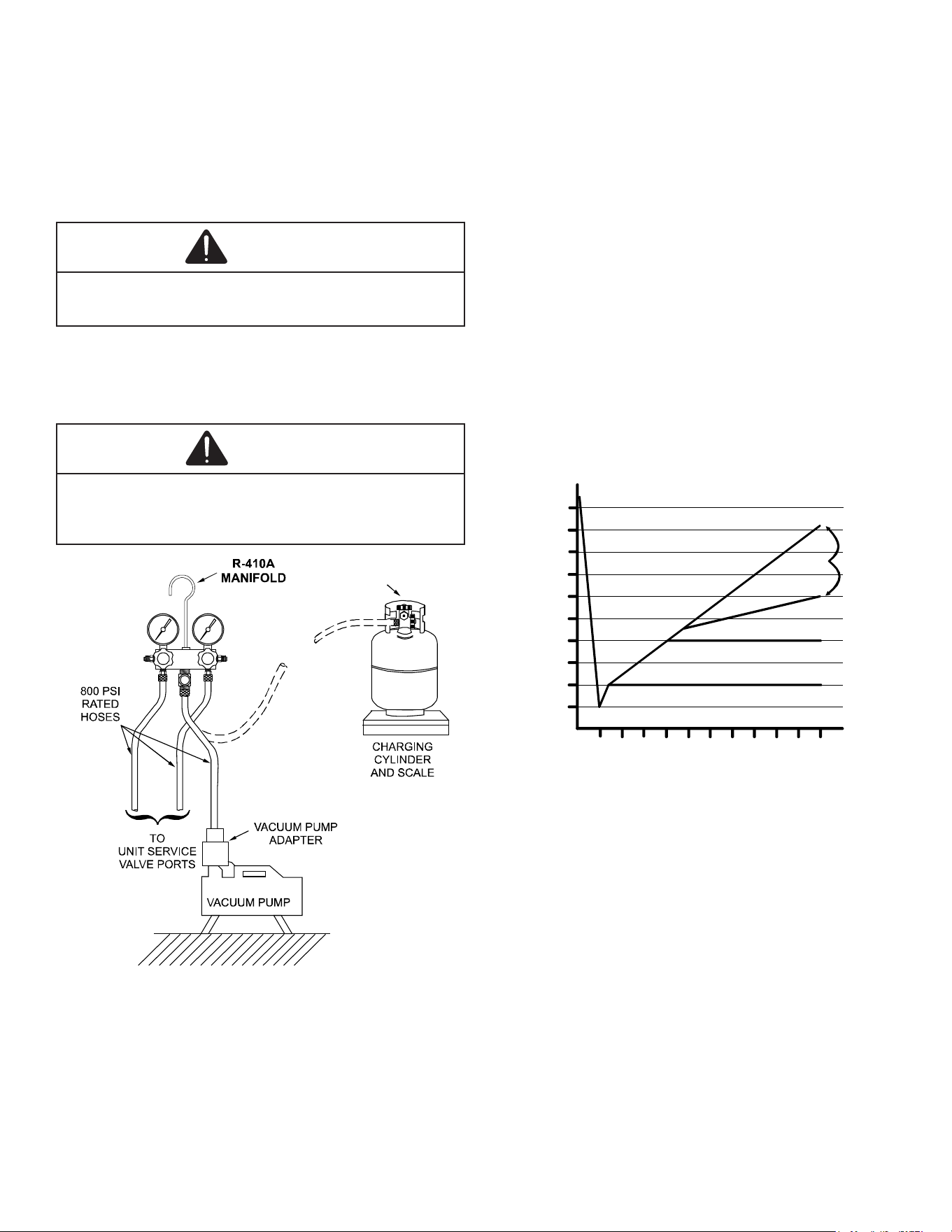
System Evacuation
Condensing unit liquid and suction valves are closed to
contain the charge within the unit. The unit is shipped with
the valve stems closed and caps installed. Do not open
valves until the system is evacuated.
WARNING
REFRIGERANT UNDER PRESSURE!
Failure to follow proper procedures may cause property
damage, personal injury or death.
NOTE: Scroll compressors should never be used
to evacuate or pump down a heat pump or air
conditioning system.
CAUTION
Prolonged operation at suction pressures less than 20
PSIG for more than 5 seconds will result in overheating of
the scrolls and permanent damage to the scroll tips, drive
bearings and internal seal.
LOW SIDE
GAUGE
AND VALVE
HIGH SIDE
GAUGE
AND VALVE
Evacuation
Deep Vacuum Method (Recommended)
The Deep Vacuum Method requires a vacuum pump
rated for 500 microns or less. This method is an eective
and ecient way of assuring the system is free of non-
condensable air and moisture. As an alternative, the Triple
Evacuation Method is detailed in the Service Manual for
this product model.
It is recommended to remove the Schrader Cores from the
service valves using a core-removal tool to expedite the
evacuation procedure.
1. Connect the vacuum pump, micron gauge, and
vacuum rated hoses to both service valves.
Evacuation must use both service valves to eliminate
system mechanical seals.
2. Evacuate the system to less than 500 microns.
3. Isolate the pump from the system and hold vacuum
for 10 minutes (minimum). Typically, pressure will rise
slowly during this period. If the pressure rises to less
than 1000 microns and remains steady, the system is
considered leak-free; proceed to system charging and
startup.
4. If pressure rises above 1000 microns but holds steady
below 2000 microns, non-condensable air or moisture
may remain or small leak is present. Return to step
2: If the same result is achieved, check for leaks and
repair. Repeat the evacuation procedure.
5. If pressure rises above 2000 microns, a leak is
present. Check for leaks and repair. Repeat the
evacuation procedure.
5000
4500
4000
3500
3000
2500
2000
1500
1000
500
0 1 2 3 4 5 6 7 8 9
10
LEAK(S)
PRESENT
MINUTES
V
ACUUM
IN
MICRONS
CONDENSIBLES OR SMALL
LEAK PRESENT
NO LEAKS
NO CONDENSIBLES
Triple Evacuation Method (Alternate)
1. Evacuate the system to 4000 microns and hold for 15
minutes. Break the vacuum with dry nitrogen, bring
the system pressure to 2-3 PSIG, and hold for 20
minutes. Release the nitrogen,
2. Evacuate to 1500 microns and hold for 20 minutes.
Break the vacuum with dry nitrogen again, bring the
system pressure back to 2-3 PSIG, and hold for 20
minutes.
3. Evacuate the system to 500 microns and hold for 60
minutes.
4. If the pressure rises to 1000 microns or less and
remains steady the system is considered leak free;
proceed to start-up.
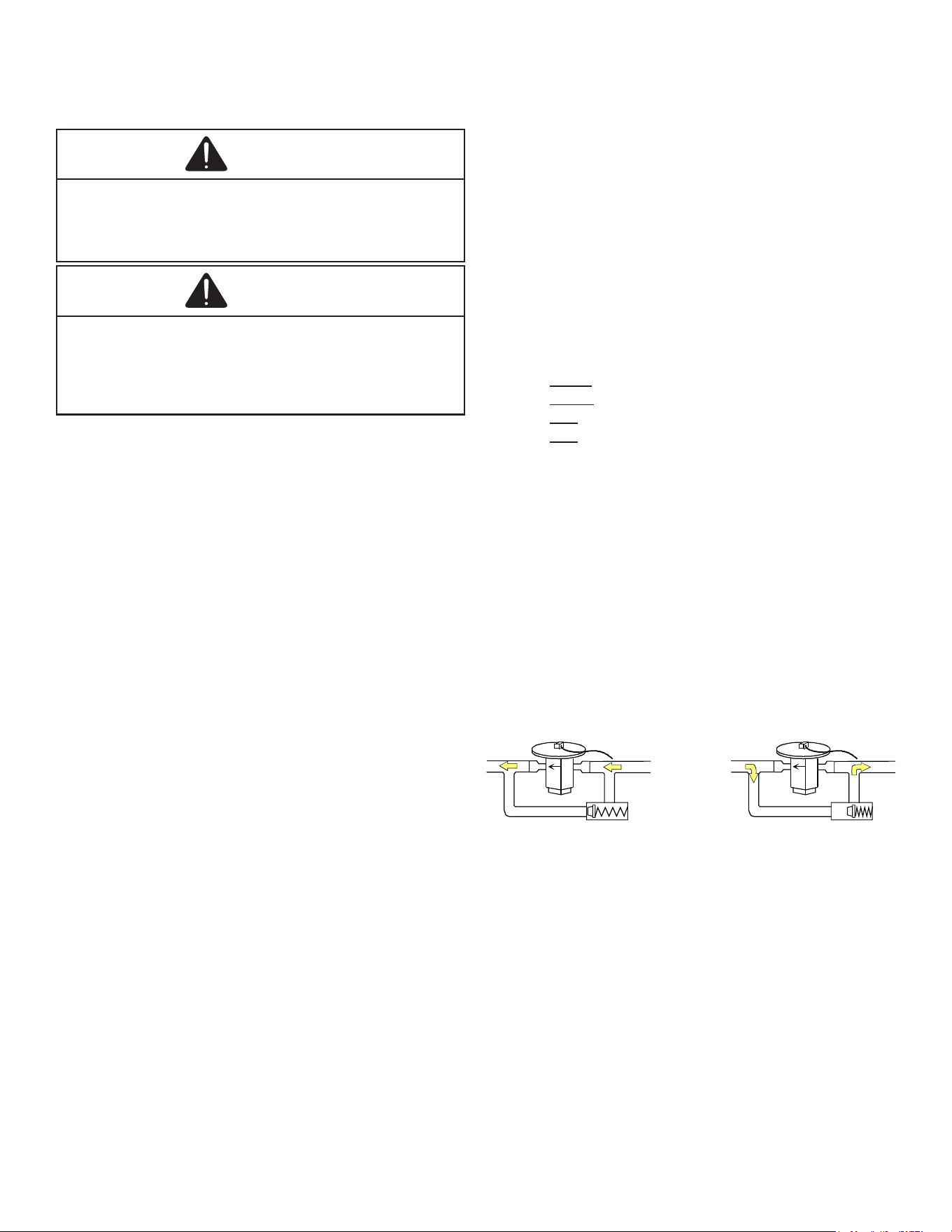
SERVICING
26
Charging
WARNING
REFRIGERANT UNDER PRESSURE!
• Do not overcharge system with refrigerant.
• Do not operate unit in a vacuum or at negative pressure.
Failure to follow proper procedures may cause property
damage, personal injury or death.
CAUTION
Only use refrigerant certified to AHRI standards. Used
refrigerant may cause compressor damage. Goodman is not
responsible for damage or the need for repairs resulting
from the use of unapproved refrigerant types or used or
recycled refrigerant. Most portable machines cannot clean
used refrigerant to meet AHRI standards.
Charge the system with the exact amount of refrigerant.
See unit nameplate for the correct refrigerant charge
amount.
NOTE: An inaccurately charged system will cause
future problems.
1. Using a charging scale, weigh in the refrigerant
charge amount listed on unit nameplate.
2. After the system will take all it will take, close the
valve on the high side of the charging manifold.
3. Start the system and charge the balance of the
refrigerant through the low side.
NOTE: R-32 should be drawn out of the storage
container or drum in liquid form due to its fractionation
properties, but should be “Flashed” to its gas state
before entering the system. There are commercially
available restriction devices that t into the system
charging hose set to accomplish this. DO NOT charge
liquid R-32 into the compressor.
4. With the system still running, close the valve on the
charging cylinder. At this time, you may still have
some liquid refrigerant in the charging cylinder hose
and will denitely have liquid in the liquid hose.
Reseat the liquid line core. Slowly open the high side
manifold valve and transfer the liquid refrigerant from
the liquid line hose and charging cylinder hose into the
suction service valve port. CAREFUL: Watch so that
liquid refrigerant does not enter the compressor.
NOTE: Even though the compressor section of a Scroll
compressor is more tolerant of liquid refrigerant,
continued oodback or ooded start conditions may
wash oil from the bearing surfaces causing premature
bearing failure.
Checking Compressor Efficiency
The reason for compressor ineciency is broken or
damaged scroll anks on Scroll compressors, reducing the
ability of the compressor to pump refrigerant vapor.
The condition of the scroll anks is checked in the following
manner.
1. Attach gauges to the high and low side of the system.
2. Start the system and run a “Cooling Performance Test.
If the test shows:
A. Below normal high side pressure.
B. Above normal low side pressure.
C. Low temperature dierence across coil.
D. Low amp draw at compressor.
And the charge is correct. The compressor is faulty -
replace the compressor.
Thermostatic Expansion Valve
The expansion valve is designed to control the rate of liquid
refrigerant ow into an evaporator coil in exact proportion
to the rate of evaporation of the refrigerant in the coil. The
amount of refrigerant entering the coil is regulated since
the valve responds to temperature of the refrigerant gas
leaving the coil (feeler bulb contact) and the pressure of the
refrigerant in the coil. This regulation of the ow prevents
the return of liquid refrigerant to the compressor.
The illustration below shows typical heatpump TXV/check
valve operation in the heating and cooling modes.
COOLING HEATING
TXV Valves
Some TXV valves contain an internal check valve thus
eliminating the need for an external check valve and
bypass loop. The three forces which govern the operation
of the valve are: (1) the pressure created in the power
assembly by the feeler bulb, (2) evaporator pressure, and
(3) the equivalent pressure of the superheat spring in the
valve.

SERVICING
27
0% bleed type expansion valves are used on indoor and
outdoor coils. The 0% bleed valve will not allow the system
pressures (High and Low side) to equalize during the
shut down period. The valve will shut o completely at
approximately 100 PSIG.
30% bleed valves used on some other models will continue
to allow some equalization even though the valve has shut-
o completely because of the bleed holes within the valve.
This type of valve should not be used as a replacement for
a 0% bleed valve, due to the resulting drop in performance.
The bulb must be securely fastened with two straps to a
clean straight section of the suction line. Application of
the bulb to a horizontal run of line is preferred. If a vertical
installation cannot be avoided, the bulb must be mounted
so that the capillary tubing comes out at the top.
THE VALVES PROVIDED ARE DESIGNED TO MEET
THE SPECIFICATION REQUIREMENTS FOR OPTIMUM
PRODUCT OPERATION. NO ADJUSTMENTS NEEDED.
NOTE: Do not use substitutes.
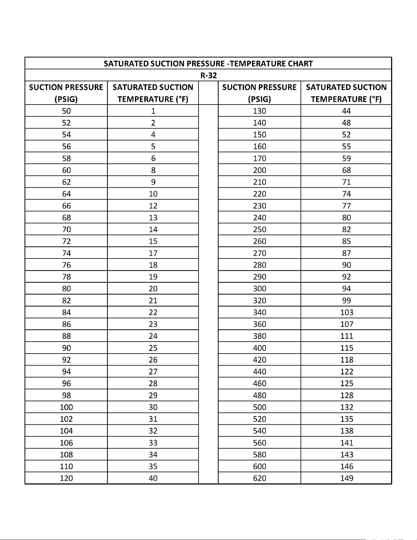
SERVICING
28
SERVICING
29
LIQUID PRESSURE
AT SERVICE VALVE (PSIG) 8 10 12 14 16 18
189 58 56 54 52 50 48
195 60 58 56 54 52 50
202 62 60 58 56 54 52
208 64 62 60 58 56 54
215 66 64 62 60 58 56
222 68 66 64 62 60 58
229 70 68 66 64 62 60
236 72 70 68 66 64 62
243 74 72 70 68 66 64
251 76 74 72 70 68 66
259 78 76 74 72 70 68
266 80 78 76 74 72 70
274 82 80 78 76 74 72
283 84 82 80 78 76 74
291 86 84 82 80 78 76
299 88 86 84 82 80 78
308 90 88 86 84 82 80
317 92 90 88 86 84 82
326 94 92 90 88 86 84
335 96 94 92 90 88 86
345 98 96 94 92 90 88
354 100 98 96 94 92 90
364 102 100 98 96 94 92
374 104 102 100 98 96 94
384 106 104 102 100 98 96
395 108 106 104 102 100 98
406 110 108 106 104 102 100
416 112 110 108 106 104 102
427 114 112 110 108 106 104
439 116 114 112 110 108 106
450 118 116 114 112 110 108
462 120 118 116 114 112 110
474 122 120 118 116 114 112
486 124 122 120 118 116 114
499 126 124 122 120 118 116
511 128 126 124 122 120 118
REQUIRED SUBCOOLING TEMPERATURE (°F)
REQUIRED LIQUID LINE TEMPERATURE
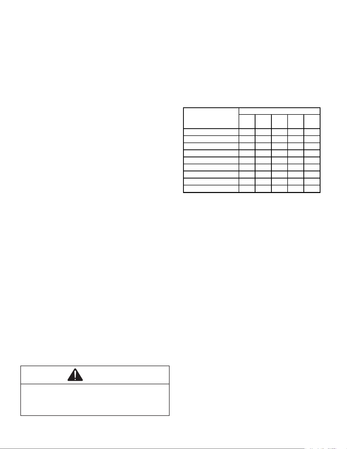
SERVICING
30
Overfeeding
Overfeeding by the expansion valve results in high suction
pressure, cold suction line, and possible liquid slugging of
the compressor.
If these symptoms are observed:
1. Check for an overcharged unit by referring to the
cooling performance charts in the servicing section.
2. Check the operation of the power element in the valve
as explained in Checking Expansion Valve Operation.
3. Check for restricted or plugged equalizer tube.
Underfeeding
Underfeeding by the expansion valve results in low system
capacity and low suction pressures.
If these symptoms are observed:
1. Check for a restricted liquid line or drier. A restriction
will be indicated by a temperature drop across the
drier.
2. Check the operation of the power element of the valve
as described in Checking Expansion Valve Operation.
Refrigerant Charge Check
Units with Fixed Orifice Devices
After completing airow measurements and adjustments
the unit’s refrigerant charge must be checked. All package
units with xed orice devices are charged using the super
heat method at the compressor suction line.
After superheat is veried, it is recommended to check unit
subcooling at the condenser coil liquid line out.
Superheat
Before checking the superheat or replacing the valve,
perform all the procedures outlined under Air Flow,
Refrigerant Charge, Expansion Valve - Overfeeding,
Underfeeding. These are the most common causes for
evaporator malfunction.
Checking Superheat
Refrigerant gas is considered superheated when its
temperature is higher than the saturation temperature
corresponding to its pressure. The degree of superheat
equals the degrees of temperature increase above the
saturation temperature at existing pressure.
PROCEDURE:
CAUTION
To prevent personal injury, carefully connect and
disconnect manifold gauge hoses. Escaping liquid
refrigerant can cause burns. Do not vent refrigerant to
atmosphere. Recover during system repair or final unit
disposal.
1. Run system at least 15 - 20 minutes to allow pressure
to stabilize.
2. Install a low side pressure gauge on the suction line
access tting.
3. Temporarily install thermometer on suction (large) line
near compressor with adequate contact and insulate
for best possible reading.
4. Record the gauge pressure corresponding
temperature and the temperature of the suction line.
5. Refer to the superheat table for proper system
superheat. Add charge to lower superheat recover
charge to raise superheat.
100
-
- - 10 10
95
- - 10 10 10
90
- - 12 15 18
85
- 10 13 17 20
80
- 10 15 21 26
75 10 13 17 25 29
70 10 17 20 28 32
65 13 19 26 32 35
60 17 25 30 33 37
Ambient Condenser
Inlet Temp (°F
Drybulb)
65
70
75
Return Air Temp. (°F Drybulb)
80
85
EXAMPLE:
A. Suction Pressure = 143
B. Corresponding Temp. °F. = 50
C. Thermometer on Suction Line = 61°F.
To obtain the degrees temperature of superheat, subtract
50.0 from 61.0°F.
The dierence is 11° Superheat. The 11° Superheat would
fall in the ± range of allowable superheat.
Superheat Formula = Suct. Line Temp. - Sat. Suct.
Temp.
Units with TXV Devices
All package units with TXV devices are charged using the
SUBCOOLING method at the liquid line. After subcooling is
checked it is recommended to check unit superheat at the
evaporator coil suction line.
Checking Subcooling
Refrigerant liquid is considered subcooled when its
temperature is lower than the saturation temperature
corresponding to its pressure. The degree of subcooling
equals the degrees of temperature decrease below the
saturation temperature at the existing pressure.
PROCEDURE:
1. Attach an accurate thermometer or preferably a
thermocouple type temperature tester to the liquid line
close to the pressure switch.
2. Install a high side pressure gauge on the liquid access
tting.

SERVICING
31
3. Record the gauge pressure and the temperature of
the line.
4. The dierence between the thermometer reading and
pressure to temperature conversion is the amount of
subcooling.
Subcooling Formula = Sat. Liquid Temp. - Liquid Line
Temp.
EXAMPLE:
A. Liquid Line Pressure = 417
B. Corresponding Temp. °F. = 120°
C. Thermometer on Liquid line = 109°F.
To obtain the amount of subcooling subtract 109°F from
120°F.
The dierence is 11° subcooling. See the specication
sheet or technical information manual for the design
subcooling range for your unit.
See R-32 Pressure vs. Temperature Chart
Expansion Valve (TXV) System Two Speed
Application
Run the unit on high stage cooling for 15-20 minutes until
refrigerant pressures stabilize. Check charge with unit on
high stage.
Follow Checking Subcooling Instructions.
NOTE: THE TXV is designed to meet the specication
requirements for optimum product operations. “No
adjustments needed to TXV”.
Heat Pump - Heating Cycle
The proper method of charging a heat pump in the heat
mode is by weighing the charge according to the total
charge listed on the rating plate.
Checking Expansion Valve Operation
1. Remove the remote bulb of the expansion valve from
the suction line.
2. Start the system and cool the bulb in a container of
ice water, closing the valve. As you cool the bulb,
the suction pressure should fall and the suction
temperature will rise.
3. Next warm the bulb in your hand. As you warm the
bulb, the suction pressure should rise and the suction
temperature will fall.
4. If a temperature or pressure change is noticed, the
expansion valve is operating. If no change is noticed,
the valve is restricted, the power element is faulty, or
the equalizer tube is plugged.
5. Capture the charge, replace the valve and drier and
evacuate.
Fixed Orifice Restriction Devices
The xed orice restriction device (owrator) used in
conjunction with the indoor coil is a predetermined bore
(I.D.).
It is designed to control the rate of liquid refrigerant ow
into an evaporator coil.
The amount of refrigerant that ows through the xed
orice restriction device is regulated by the pressure
dierence between the high and low sides of the system.
In the cooling cycle when the outdoor air temperature rises,
the high side condensing pressure rises. At the same time,
the cooling load on the indoor coil increases, causing the
low side pressure to rise, but at a slower rate.
Since the high side pressure rises faster when the
temperature increases, more refrigerant ows to the
evaporator, increasing the cooling capacity of the system.
When the outdoor temperature falls, the reverse takes
place. The condensing pressure falls, and the cooling loads
on the indoor coil decreases, causing less refrigerant ow.
If a restriction should become evident, proceed as follows:
1. Recover refrigerant charge.
2. Remove the orice assembly and clean or replace.
3. Replace liquid line drier, evacuate and recharge.
Checking Equalization Time
During the “OFF” cycle, the high side pressure bleeds to
the low side through the xed orice restriction device.
Check equalization time as follows:
1. Attach a gauge manifold to the suction and liquid line
access ttings.
2. Start the system and allow the pressures to stabilize.
3. Stop the system and check the time it takes for the
high and low pressure gauge readings to equalize.
If it takes more than seven (7) minutes to equalize, the
restriction device is inoperative. Replace, install a liquid line
drier, evacuate and recharge.
Checking Restricted Liquid Line
When the system is operating, the liquid line is warm to the
touch. If the liquid line is restricted, a denite temperature
drop will be noticed at the point of restriction. In severe
cases, frost will form at the restriction and extend down the
line in the direction of the ow.
Discharge and suction pressures will be low, giving the
appearance of an undercharged unit. However, the unit will
have normal to high subcooling.
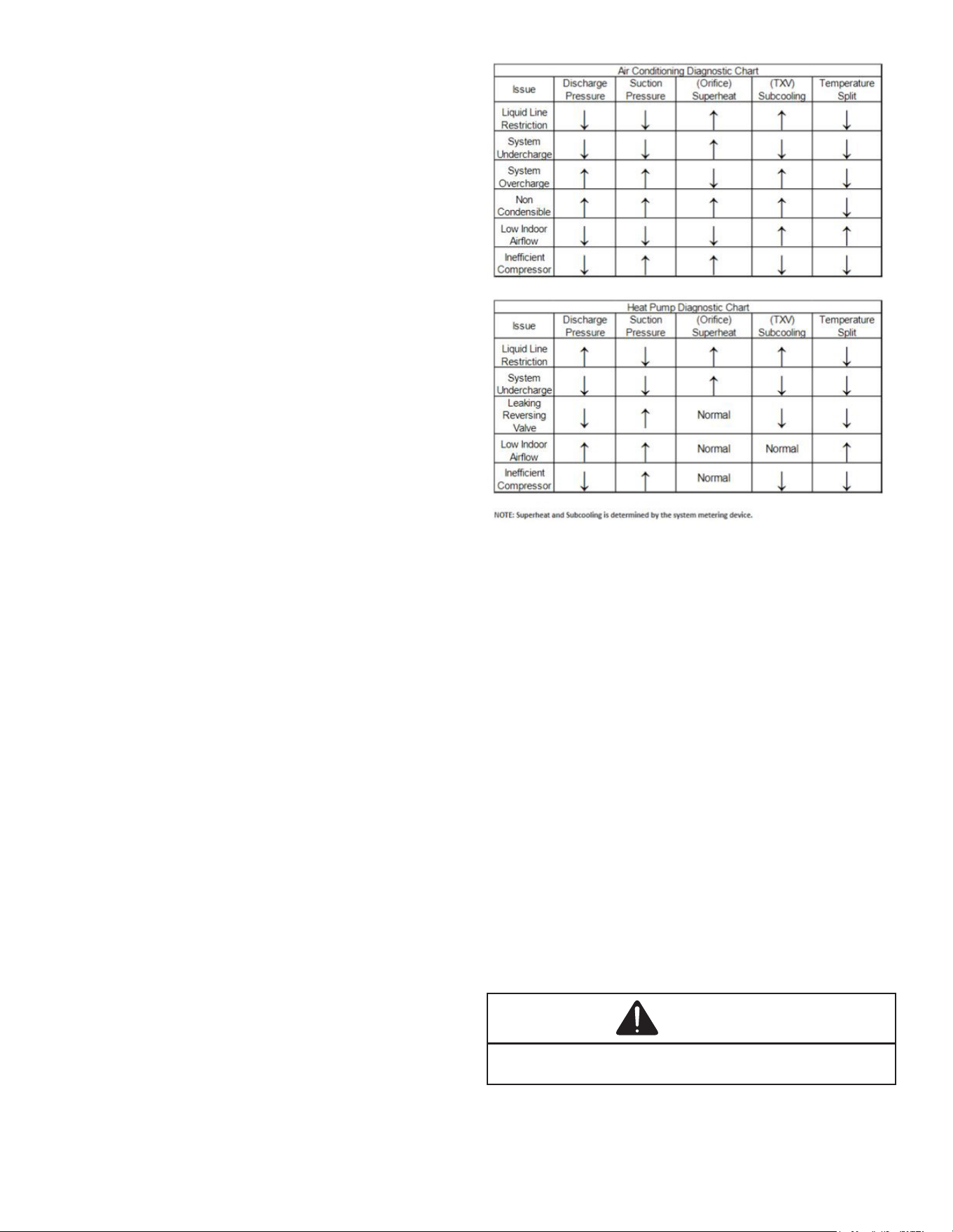
SERVICING
32
Locate the restriction, replace the restricted part, replace
drier, evacuate and recharge.
Refrigerant Overcharge
An overcharge of refrigerant is normally indicated by
excessively high head pressure and/or liquid return to the
compressor.
If high head pressure is not indicated, an overcharge or a
system containing non-condensables could be the problem.
If overcharging is indicated:
1. Start the system.
2. Remove small quantities of gas from the suction line
dill valve until the head pressure is reduced to normal.
3. Observe the system while running a cooling
performance test, if a shortage of refrigerant
is indicated, then the system contains non-
condensables.
Non-Condensables
Check for non-condensables:
1. Shut down the system and allow the pressures to
equalize for a minimum of 15 minutes.
2. Take a pressure reading.
3. Compare this pressure to the temperature of the
coldest coil since this is where most of the refrigerant
will be. If the pressure indicates a higher temperature
than that of the coil temperature, non-condensables
are present.
To remove the non-condensables:
1. Remove the refrigerant charge.
2. Replace and/or install liquid line drier.
3. Evacuate and recharge.
Compressor Burnout
When a compressor burns out, high temperature develops
causing the refrigerant, oil and motor insulation to
decompose forming acids and sludge.
If a compressor is suspected of being burned-out, attach
a refrigerant hose to the liquid line dill valve and properly
remove and dispose of the refrigerant.
NOTICE: Violation of EPA regulations may result in
nes or other penalties.
Now determine if a burn out has actually occurred. Conrm
by analyzing an oil sample using a Sporlan Acid Test Kit,
AK-3 or its equivalent.
Remove the compressor and obtain an oil sample from the
suction stub. If the oil is not acidic, either a burnout has not
occurred or the burnout is so mild that a complete clean-up
is not necessary.
If acid level is unacceptable, the system must be cleaned
by using the clean-up drier method.
CAUTION
Do not allow the sludge or oil to contact the skin. Severe
burns may result.
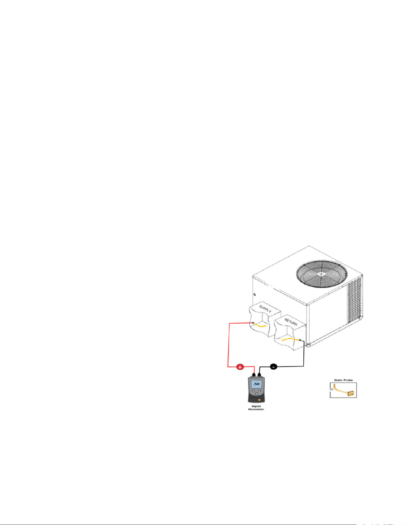
SERVICING
33
NOTE: The Flushing Method using R-11 refrigerant
is no longer approved by Goodman® Manufacturing
Company, L.P.
Suction Line Drier Clean-Up Method
The POE oils used with R-32 refrigerant is an excellent
solvent. In the case of a burnout, the POE oils will remove
any burnout residue left in the system. If not captured by
the refrigerant lter, they will collect in the compressor
or other system components, causing a failure of the
replacement compressor and/or spread contaminants
throughout the system, damaging additional components.
The suction line lter drier should be installed as close to
the compressor suction tting as possible. The lter must
be accessible and be rechecked for a pressure drop after
the system has operated for a time. It may be necessary to
use new tubing and form as required.
NOTE: At least twelve (12) inches of the suction line
immediately out of the compressor stub must be
discarded due to burned residue and contaminates.
1. Remove compressor discharge line strainer.
2. Remove the liquid line drier and expansion valve.
3. Purge all remaining components with dry nitrogen or
carbon dioxide until clean.
4. Install new components including liquid line drier.
5. Braze all joints, leak test, evacuate, and recharge
system.
6. Start up the unit and record the pressure drop across
the drier.
7. Continue to run the system for a minimum of twelve
(12) hours and recheck the pressure drop across the
drier. Pressure drop should not exceed 6 PSIG.
8. Continue to run the system for several days,
repeatedly checking pressure drop across the suction
line drier. If the pressure drop never exceeds the
6 PSIG, the drier has trapped the contaminants.
Remove the suction line drier from the system.
9. If the pressure drop becomes greater, then it must be
replaced and steps 5 through 9 repeated until it does
not exceed 6 PSIG.
NOTICE: Regardless, the cause for burnout must be
determined and corrected before the new compressor
is started.
Reversing Valve Replacement
Remove the refrigerant charge from the system.
When brazing a reversing valve into the system, it is of
extreme importance that the temperature of the valve does
not exceed 250°F at any time.
Wrap the reversing valve with a large rag saturated with
water. “Re-wet” the rag and thoroughly cool the valve after
each brazing operation of the four joints involved. The wet
rag around the reversing valve will eliminate conduction of
heat to the valve body when brazing the line connection.
The use of a wet rag sometimes can be a nuisance. There
are commercial grades of heat absorbing paste that may
be substituted.
After the valve has been installed, leak test, evacuate and
recharge.
Checking External Static Pressure
The minimum and maximum allowable duct static pressure
is found in the Technical Information Manual.
Too great of an external static pressure will result in
insucient air that can cause icing of the coil, whereas too
much air can cause poor humidity control, and condensate
to be pulled o the evaporator coil causing condensate
leakage. Too much air can cause motor overloading and in
many cases this constitutes a poorly designed system. To
determine proper air movement, proceed as follows:
1. Using a manometer measure the static pressure
of the return duct at the inlet of the unit, (Negative
Pressure).
Total External Static
2. Measure the static pressure of the supply duct,
(Positive Pressure).
3. Add the two readings together.
NOTE: Both readings may be taken simultaneously
and read directly on the manometer as shown in the
illustration above, if so desired.
4. Consult proper table for quantity of air.
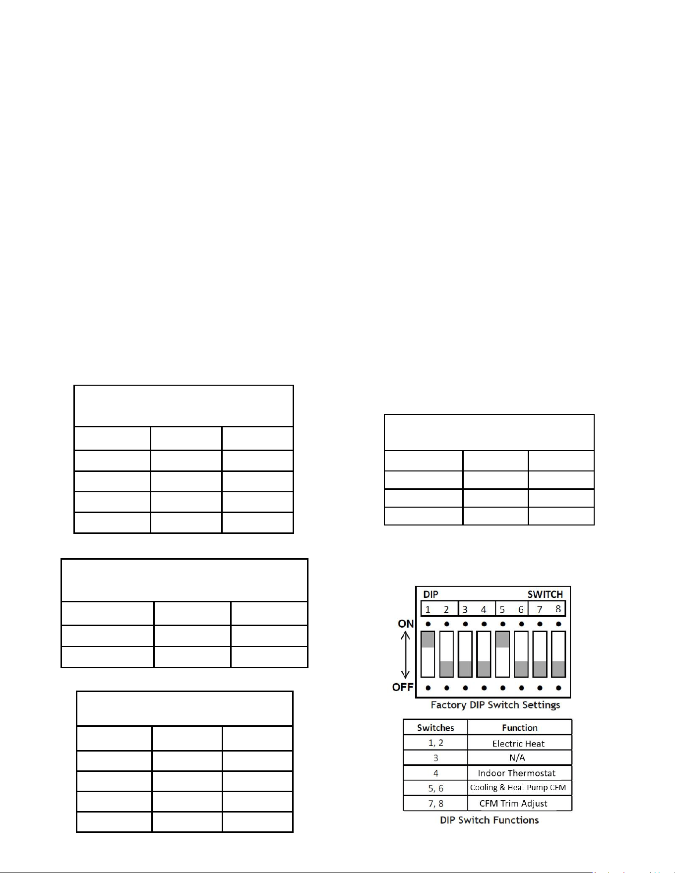
SERVICING
34
If the external static pressure exceeds the minimum or
maximum allowable statics, check for closed dampers, dirty
lters, undersized or poorly laid out ductwork.
Adjusting Airflow
EEM Motor
The blower motor speed for the EEM motor is controlled by
three 24V low voltage leads: green, yellow, and white. The
green lead sets the speed for fan-only mode. The yellow
lead sets the speed for cooling and heat pump heating
mode (if applicable).
EEM Motor Speed Adjustment
The white lead sets the speed for electric heat mode
(emergency heat and second stage heat, if applicable).
The leads are factory connected as follows: Green to T1,
Yellow to T2, and White to T3. T1 is the low speed setting
and is dedicated to fan-only mode. T2 is medium speed
cooling and T3 is medium speed heating. T4 is high speed
cooling and T5 is high speed heating. To adjust the blower
speed, move the yellow and/or white wires to T4 and T5.
NOTE: If more than one lead is energized at the same
time, the motor will use the higher speed setting.
ECM Motor Speed Adjustment
Each ECM blower motor has been preprogrammed for
operation at 4 distinct air ow levels when operating in
Cooling/Heat Pump mode or Electric Heat mode. These 4
distinct levels may also be adjusted slightly lower or higher
if desired. The adjustment between levels and the trim
adjustments are made by changing the dip switch(s) either
to an “OFF” or “ON” position. See Blower Performance
Data tables in installation manual.
DIP Switch Functions
The ECM motor has an electronic control that contains
eight (8) 2-position dip switches. The function of these dip
switches is shown in Table below.
For APHH5[24-36]41 models, dip switch 4 must be set
to ON. Dip switch 4 must be set to OFF for the two-stage
compressor models APHH5[42-60]41. Dip switch 4 ON
energizes Y1 signal to the ECM motor anytime Y/Y2 is
energized. The indoor motor will not operate properly if
switch is not set correctly for the correct model.
Speed Tap Switch 1 Switch 2
A OFF OFF
B ON OFF
C OFF ON
D ON ON
Electric Heat
DIP Switch Settings
Thermostat Switch 3 Switch 4
Single-Sta ge N/A ON
Two-Stage N/A OFF
DIP Switch Settings for
Single & Two-Stage Thermostat
Speed Tap Switch 5 Switch 6
A OFF OFF
B ON OFF
C OFF ON
D ON ON
Cooling/HP DIP Switch Settings
CFM Switch 7 Switch 8
Plus 10% ON OFF
Normal OFF OFF
Minus 10% OFF ON
Speed Tap Adjustment
Through DIP Switches
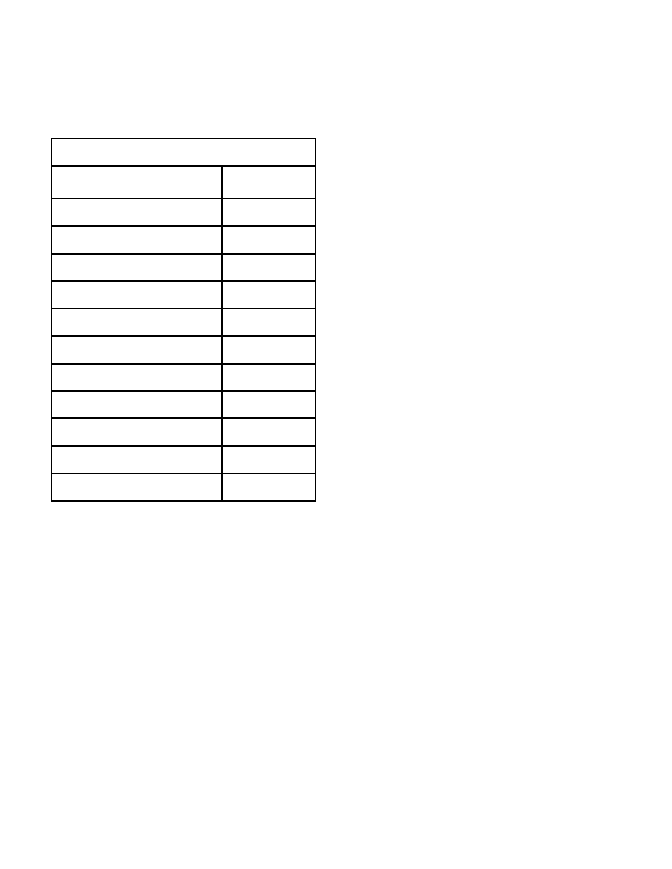
SERVICING
35
The below table details the required minimum airow of the unit to ensure proper function of the refrigerant detection
system.
DO NOT set the system that would permit call for a lower airow than the below table identies for the associated unit.
Model
[ft
3
/min]
(A/G)PHM32431 162
(A/G)PHM33031 153
(A/G)PHM33631 157
(A/G)PHM34231 180
(A/G)PHM34831 250
(A/G)PHM36031 211
(A/G)PHM52431 167
(A/G)PHM53031 203
(A/G)PHM53631 235
(A/G)PHM54231 223
(A/G)PHM54831 224
Minimum Airflow
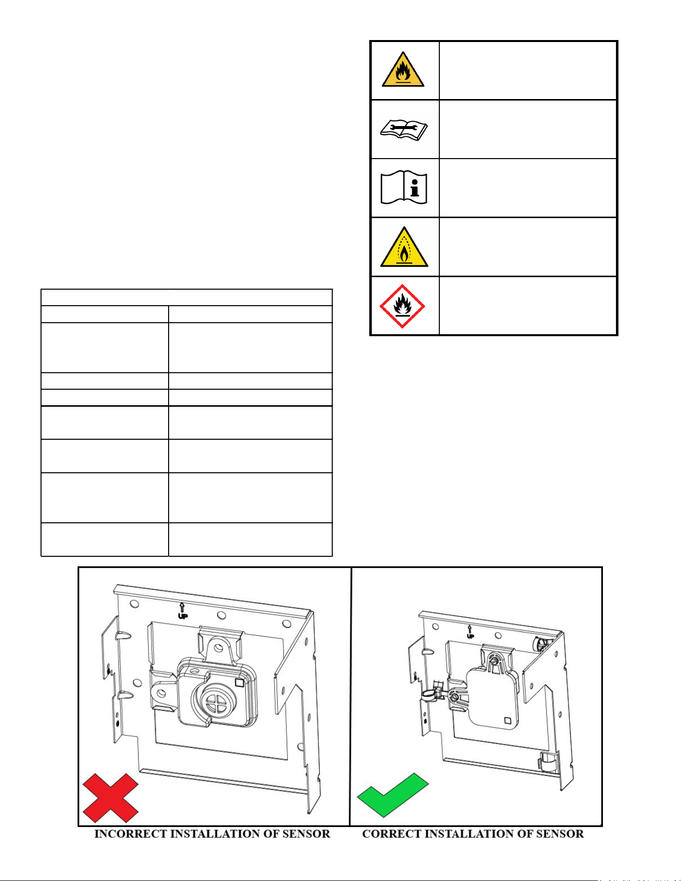
SERVICING
36
Refrigerant Detection System
DETECTION SYSTEMS shall only be replaced with
sensors specied by the manufacturer. If REFRIGERANT
SENSOR requires replacement, please replace with
Sensata R32 Sensor PN#RGD-00ML12 (Daikin
PN#SER2A08011).
Before servicing, identify the mode of operation of the
system by reading the LED ashing pattern on the PCB
within the control box and matching the LED ashing
pattern with mode of operation in the A2L PCB fault code
table on the wiring diagram which is attached on the back
side of the control box panel.
When replacing the A2L sensor, ensure that the arrows on
the A2L sensor and the sensor bracket are pointing in the
same direction.
warning; flammable materials
service indicator; read technical
manual
operator's manual; operating
instructions
warning; low burning velocity
material
UN GHS flame symbol
MODE LED FLASHING PATTERN
NORMAL OPERATION
SLOW LED FLASHING PATTERN
(2 SECONDS ON 2 SECONDS OFF)
R-32 LEAK ALARM FAST LED FLASHING PATTERN
DELAY MODE LED WILL BE ON CONTINUOUSLY
SYSTEM
VERIFICATION MODE
FAST LED FLASHING PATTERN
CONTROL BOARD
INTERNAL FAULT
LED WILL FLASH 2 TIMES AND
THEN BE OFF FOR 5 SECONDS
R32 SENSOR
COMMUNICATION FAULT
LED WILL FLASH 3 TIMES AND
THEN BE OFF FOR 5 SECONDS
R32 SENSOR FAULT
LED WILL FLASH 4 TIMES AND
THEN BE OFF FOR 5 SECONDS
LED STATUS
37
TROUBLESHOOTING
SYMPTOM
High head - low suction
a.
Restriction in liquid line or
TXV not functioning
a.
Remove or replace with proper size TXV.
High head - high or normal suction
a.
In Cooling: Dirty condenser coil
a.
Clean coil
In Heating: Dirty filter, Dirty indoor coil
b.
Overcharged
b.
Correct System charge
c.
In Cooling: Condenser fan not running
c.
In Heating: Indoor blower not running
c.
Repair or Replace
a.
Incorrect TXV.
a.
Replace with correct TXV
b.
Defective compressor valves
b.
Replace compressor
c.
TXV not functioning properly
c.
Check for debris in TXV or deformed TXV.
Remove debris or replace TXV.
d.
Incorrect TXV setting d.
Check Super Heat
a.
Power off or loose electrical connection
a. Check for unit voltage at contactor in unit
b.
Thermostat out of calibration set too high
b.
Reset
c.
Defective contactor
c.
Check for 24 volts at contactor coil replace if
contacts are open
d.
Blown fuses or tripped breaker
d.
Replace fuse or reset breaker
e.
Transformer defective
e.
Check wiring - replace transformer
f.
High or low pressure control open
(Optional)
f.
Check high pressure control or check unit
charge
High pressure control opens at 610 psig
Low pressure control opens at 22 psig
g.
Compressor overload contacts open
g.
Replace compressor
NOTE: Wait at least 2 hours for overload to reset
Condenser fan runs,
compressor doesn't
a.
Loose connection
a.
Check for unit voltage at compressor check &
tighten all connections
b.
Compressor stuck, grounded or open
winding
open internal overload
b.
Wait at least 2 hours for overload to reset If still
open, replace the compressor.
c.
Low voltage connection
c.
At compressor terminals, voltage must be within
10 % of nameplate volts when unit is operating
d.
Capacitor weak, open, or shorted
d.
Check capacitor. If defective, replace.
Low suction - cool compressor
a.
In Cooling: Low indoor airflow
a.
Iced evaporator coil
In Heating: Dirty outdoor coil, defective
defrost thermostat, defective defrost
control board, outdoor fan not running, low
refrigerant charge.
b.
Low airflow
b.
Check - should be approximately 400 CFM per
ton, dirty air filters, all duct outlets open
c.
Low refrigerant charge
c.
Properly charge unit
d.
Operating unit in cooling mode below 65°F
outdoor temperature
d.
Install or check low ambient control, should be
open below 65°F outdoor temperature
a.
Defective overload protector
a.
Replace - check for correct voltage
b.
Unit cycling on low pressure control
b.
Check refrigerant charge and / or airflow
c.
High pressure switch cuts out c.
Check airflow (indoor & outdoor),
check expansion device
a.
a.
Increase speed of blower or reduce restriction
replace air filters
a.
Excessive load
a.
Recheck load calculation
b.
Defective compressor
b.
Replace
c.
Reversing valve not seating properly.
c.
Replace
a.
Improperly sized unit
a.
Recalculate load
b.
Improper airflow
b.
Check - should be approximately 400 CFM per ton
c.
Incorrect refrigerant charge.
c.
Charge per procedure attached to unit service
panel
d. Incorrect voltage
d.
At compressor terminals, voltage must be within
10% of nameplate volts when unit is operating
Increase speed of blower or reduce restriction -
replace air filters
Insufficient cooling
High suction pressure
REMEDY
POSSIBLE CAUSE
Compressor short cycles
Registers sweat
Low airflow
Low head - high suction
Unit will not run
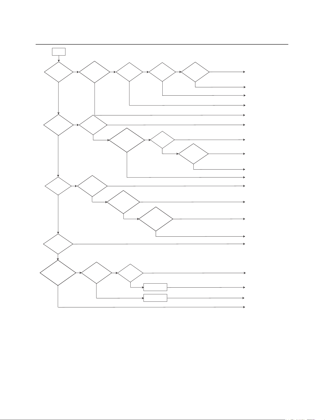
38
Troubleshooting AC- Cooling
No
Cooling
Yes
No
No
208/240v at
L1 & L2 to
contactor?
Check wiring between contactor
and transformer
208/240v at
transformer
primary?
Check thermostat or wiring
24 volts at
transfomer
secondary?
Check low voltage fuse
thermostat or wiring
24v between
Y & C at
thermostat?
No
Are both
compressor and
condenser fan
running?
Check open safety thermostat or
wiring
Yes
Check wiring replace contactor
Check line voltage wiring to
Replace contactor
Check disconnect circuit
breaker fuses
No No
Is compressor or
condenser fan running
independently?
No
Replace transformer
24v
between R
& C at
thermostat?
Check capacitor wiring
Check thermostat or wiring
Check wiring or motor controller
No
Is there 24v at
contractor
coil?
Check capacitor, compressor
wiring, or condenser fan
Check
No
No
Is contactor
plunger pulled
in?
No
Yes
Is indoor
blower motor
running?
0vac across L1
& T1 terminals
of contactor?
Yes
24v between C
& G at
thermostat?
Yes
No No
208/240v
between L & N
at motor
harness
Yes
No
Yes
Yes
Check for 24v
between C &
T/1/2/3/4/5 terminal
at motor
Yes
Is indoor
blower motor
speed correct?
See “airflow adjustments”
section
No
Yes
Yes
Yes
Yes
No
Yes
Yes
Are refrigerant
pressures and
superheat/subcooling
correct?
Verify refrigerant charge
Yes
No
Pressure test, evacuate and
recharge system
Pressure test, evacuate and
recharge system
Check for
leak in
refrigerant
system
Yes
No
Check for
restriction in
system
Yes
Clear restriction
Repair Leak
No
Cooling mode operation
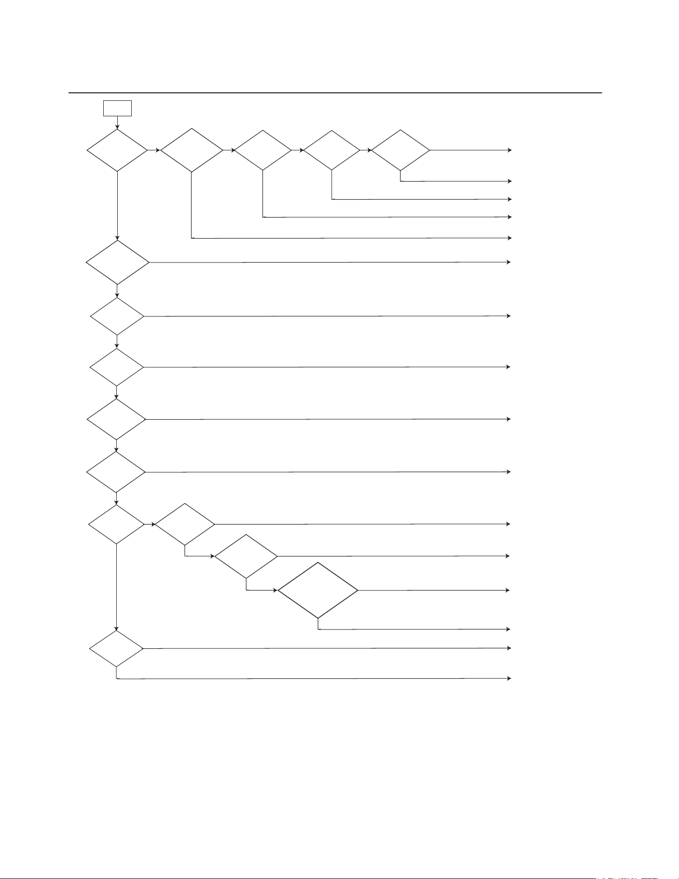
39
Troubleshooting AC -Heating (Electric Heat)
No Heat
Yes
No No
208/240v at
L1 & L2 at
contactor?
Check wiring between contactor
and transformer
208/240v at
transformer
primary?
Check open limit switch
thermostat or wiring
24 volts at
transfomer
secondary?
Check low voltage fuse
thermostat or wiring
24v between
C & W at
thermostat?
Check circuit breaker
disconnect fuses
No No
Replace transformer
24v between
R & C at
thermostat?
No
Is the blower
motor
running?
Check thermostat or wiring
Yes
Check line voltage wiring to
Check wiring or motor controller
Check blower motor
See “Airflow Adjustment” section
No
24v between
C & G at
thermostat?
Is indoor
blower speed
correct?
No
No
208/240v
at heater
kit
contactor?
24v at
contactor coil?
Check circuit breaker or wiring
to heater kit
Check open limit switch or wiring
No
Yes
Yes
Yes
Yes
Yes
No
Yes
No
Is there 24v between
C & T1/2/3/4/5
terminals at motor
harness?
Yes
Yes
Heat mode operation (Electric
Heat)
Are contactor
contacts
closed?
Yes
No
Check
0vac across
L1 & T1 of
contactor?
Yes
No
Replace contactor
Does heater
elements
come on?
Yes
No
Check for open fusible link
Yes
208/240v
between L & N
at motor
harness?
Yes
No
40
Troubleshooting Heat Pump - Cooling (1 Stage)
No
Cooling
Yes
No
No
208/240v at
L1 & L2 to
contactor?
Check wiring between contactor
and transformer
208/240v at
transformer
primary?
Check thermostat or wiring
24 volts at
transfomer
secondary?
Check low voltage fuse
thermostat or wiring
24v between
Y & C at
thermostat?
No
24v to
reversing vave
coil?
Check thermostat & wiring
Yes
Check wiring or replace
contactor
Check line voltage wiring to
blower motor
Replace contactor
Check disconnect circuit
breaker fuses
No No
Is compressor or
condenser fan running
independently?
No
Replace transformer
24v
between R
& C at
thermostat?
Check capacitor wiring
Check thermostat or wiring
Check low voltage wiring to
motor or motor controller
No
24v at DFC
terminals O-RV
& C-RV?
Check open compressor
overload faulty compressor
capacitor or wiring
Check blower motor
No
No
Is contactor
plunger pulled
in?
No
Yes
Is indoor
blower motor
running?
0vac across L1
& T1 terminals
of contactor?
Yes
208/240v
between C & G
at thermostat?
Yes
No No
208/240v
between L & N
at motor
harness?
Yes
No
Yes
Check for 24v
between C &
T1/2/3/4/5 terminals
at motor
Yes
Is indoor
blower motor
speed correct?
See “airflow adjustments”
section
No
Yes
Yes
Yes
Yes
No
Yes
Yes
24v at DFC
terminals C &
O?
Yes
Yes
Replace PCB
No
Repalce reversing valve coil
Are both
compressor and
condenser fan
motor running?
Is there 24v
at contactor
coil?
No
No
24v at
terminals
CNT & C on
DFC?
No
Yes
Check open safety or faulty
wiring
Check contactor coil
Compressor
running?
Yes
Condenser
fan motor
not running
0v at DF1 &
DF2 terminals
on DFC?
No
No
Replace PCB
Yes
Check capacitor condenser fan
motor or wiring
Yes
Is unit
producing
cool air?
Check faulty reversing valve or
faulty compressor
No
Yes
Yes
41
Troubleshooting Heat Pump - Cooling (1 Stage)
Are refrigerant
pressures and
superheat/subcooling
correct?
Verify refrigerant charge
Yes
No
Pressure test, evacuate and
recharge system
Pressure test, evacuate and
recharge system
Check for
leak in
refrigerant
system
Yes
No
Check for
restriction in
system
Yes
Clear restriction
Repair Leak
No
Heat pump cooling mode
operation
Yes
42
Troubleshooting Heat Pump - Cooling (2 Stage)
No
Cooling
Yes
No
No
208/240v at
L1 & L2 to
contactor?
Check wiring between contactor
and transformer
208/240v at
transformer
primary?
Check thermostat or wiring
24 volts at
transfomer
secondary?
Check low voltage fuse
thermostat or wiring
24v
between Y1
& C at
thermostat?
No
24v to
reversing vave
coil?
Check thermostat & wiring
Yes
Check wiring replace contactor
Check line voltage wiring to
blower motor
Replace contactor
Check disconnect circuit
breaker fuses
No No
Is compressor or
condenser fan running
independently
No
Replace transformer
24v
between R
& C at
thermostat?
Check capacitor wiring
Check thermostat or wiring
Check low voltage wiring or
motor controller
No
24v at DFC
terminals O-RV
& C-RV?
Check open compressor
overload faulty compressor
capacitor or wiring
No
No
Is contactor
plunger pulled
in?
No
Yes
Is indoor
blower motor
running?
0vac across L1
& T1 terminals
of contactor?
Yes
24v between
C & G at
thermostat?
Yes
No No
208/240v
between L & N
at motor
harness?
Yes
No
Yes
24v between C &
T 1/2/3/4/5 at
motor harness?
Is indoor
blower motor
speed correct?
See “airflow adjustments”
section
No
Yes
Yes
Yes
Yes
No
Yes
Yes
24v at DFC
terminals C &
O?
Yes
Yes
Replace PCB
No
Repalce reversing valve coil
Are both
compressor and
condenser fan
motor running?
Is there 24v
at contactor
coil?
No
No
24v at
terminals
CNT & C on
DFC?
No
Yes
Check open safety or faulty
wiring
Check contactor coil
Compressor
running?
Yes
Condenser
fan motor
not running
0v at DF1 &
DF2 terminals
on DFC?
No
No
Replace PCB
Yes
Check capacitor condenser fan
motor or wiring
Yes
Is unit
producing
cool air?
Check faulty reversing valve or
faulty compressor
No
Yes
Check blower motor
First Stage
Cooling
Operation
Yes
Yes
43
Troubleshooting Heat Pump - Cooling (2 Stage)
Are refrigerant
pressures and
superheat/subcooling
correct
Verify refrigerant charge
Yes
No
Pressure test, evacuate and
recharge system
Pressure test, evacuate and
recharge system
Check for
leak in
refrigerant
system
Yes
No
Check for
restriction in
system
Yes
Check for restriction
or defective TXV
Repair Leak
No
Second stage cooling operating
Yes
Is there 24v
between C & Y2 at
thermostat?
No
Check thermostat & wiring
Check thermostat & wiring
Is there 24v at
compressor
contactor relay
coil?
No
Yes
Yes
Are relay
contacts closed?
Should read 0v at
pins 2 & 4
No
Replace relay
Is there 18-28vdc
at compressor
unloader plug
harness?
No
Yes
Replace unloader plug
Does compressor
change from part load
to full load? Verified
by amp draw
No
Yes
Replace compressor
Yes
Does blower
change to 2nd
stage cooling
speed?
No
24v between C &
T 1/2/3/4/5 at
motor harness?
Check thermostat and wiring or
motor controller
Yes
Check blower motor
No
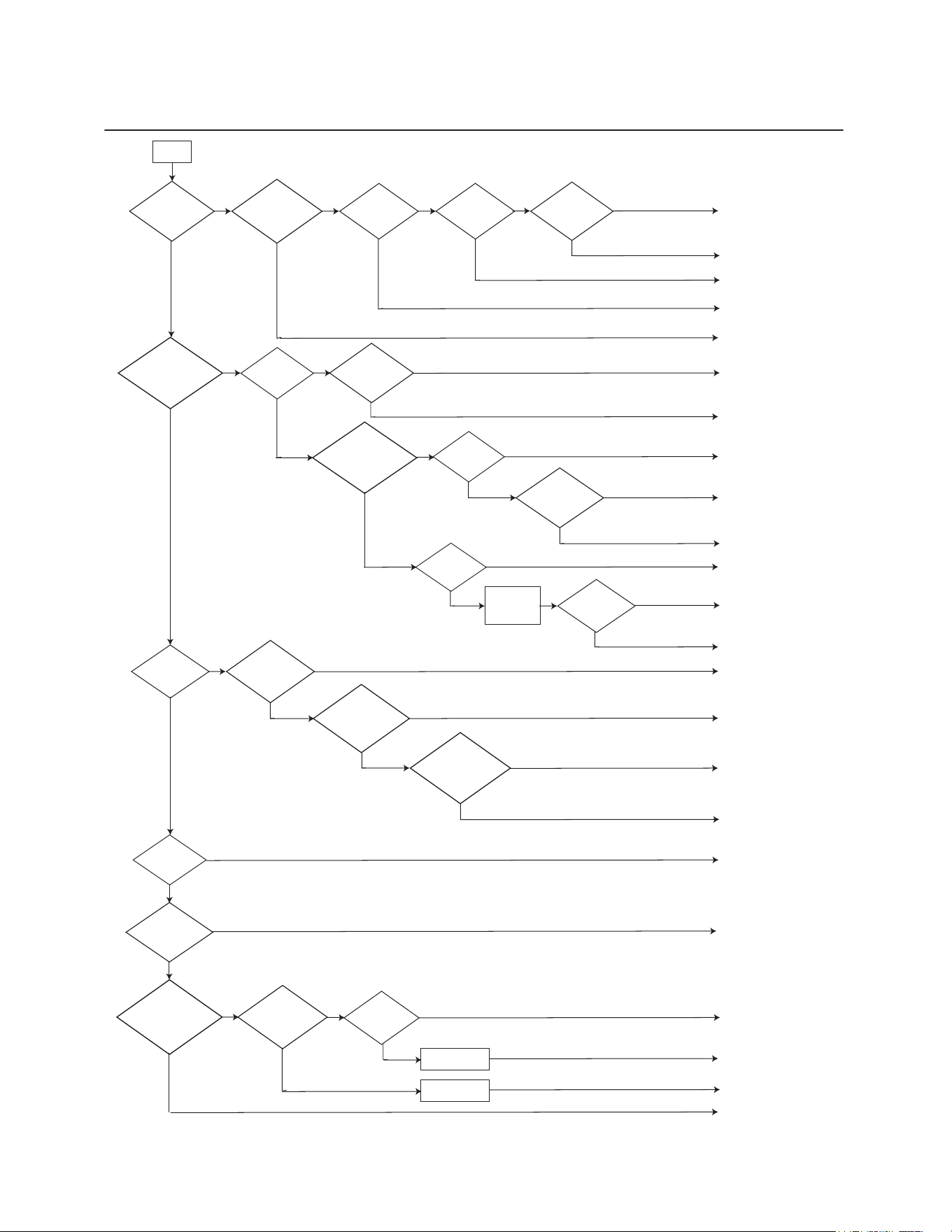
44
Troubleshooting Heat Pump - Heating (1 Stage)
No Heat
Yes
No
No
208/240v at
L1 & L2 to
contactor?
Check wiring between contactor
and transformer
208/240v at
transformer
primary?
Check thermostat or wiring
24 volts at
transfomer
secondary?
Check low voltage fuse
thermostat or wiring
24v between
Y & C at
thermostat?
Check wiring replace contactor
Check line voltage wiring to
blower motor
Replace contactor
Check disconnect circuit
breaker fuses
No No
Is compressor or
condenser fan running
independently
No
Replace transformer
24v
between R
& C at
thermostat?
Check capacitor wiring
Check thermostat or wiring
Check low voltage wiring to
motor controller
Check open compressor
overload faulty compressor
capacitor or wiring
No
No
Is contactor
plunger pulled
in?
No
Yes
Is indoor
blower motor
running?
0vac across L1
& T1 terminals
of contactor?
Yes
24v between
C & G at
thermostat?
Yes
No No
208/240v
between L & N
at motor
harness?
Yes
No
Yes
Check for 24v
between C &
T1/2/3/4/5 terminals
at motor
Is indoor
blower motor
speed correct?
See “airflow adjustments”
section
No
Yes
Yes
Yes
Yes
No
Yes
Yes
Are both
compressor and
condenser fan
motor running?
Is there 24v
at contactor
coil?
No
No
24v at
terminals
CNT & C on
DFC?
No
Yes
Check open safety or faulty
wiring
Check contactor coil
Compressor
running?
Yes
Condenser
fan motor
not running
0v at DF1 &
DF2 terminals
on DFC?
No
No
Replace PCB
Yes
Check capacitor condenser fan
motor or wiring
Yes
Is unit
producing
hot air?
Check faulty reversing valve or
faulty compressor
No
Yes
Check blower motor
Are refrigerant
pressures and
superheat/subcooling
correct?
Verify refrigerant charge
Yes
No
Pressure test, evacuate and
recharge system
Pressure test, evacuate and
recharge system
Check for
leak in
refrigerant
system
Yes
No
Check for
restriction in
system
Yes
Clear restriction
Repair Leak
No
Heat pump heating operation
Yes
Yes
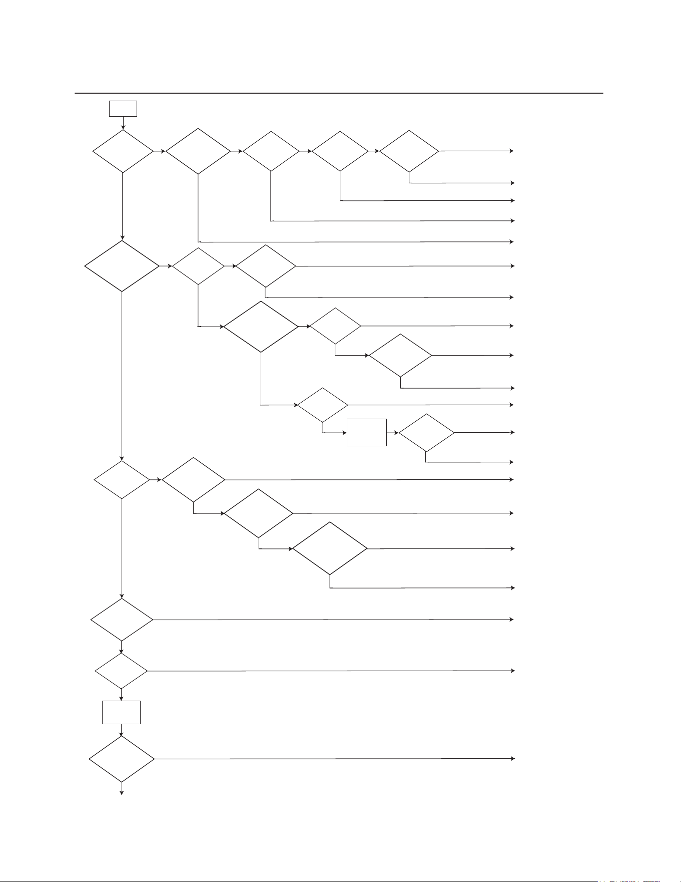
45
Troubleshooting Heat Pump - Heating (2 Stage)
No Heat
Yes
No
No
208/240v at
L1 & L2 to
contactor?
Check wiring between contactor
and transformer
208/240v at
transformer
primary?
Check thermostat or wiring
24 volts at
transfomer
secondary?
Check low voltage fuse
thermostat or wiring
24v
between Y
& C at
thermostat?
Check wiring replace contactor
Check line voltage wiring to
blower motor
Replace contactor
Check disconnect circuit
breaker fuses
No No
Is compressor or
condenser fan running
independently?
No
Replace transformer
24v
between R
& C at
thermostat?
Check capacitor wiring
Check thermostat or wiring
Check low voltage wiring to
motor or motor controller
Check open compressor
overload faulty compressor
capacitor or wiring
No
No
Is contactor
plunger pulled
in?
No
Yes
Is indoor
blower motor
running?
0vac across L1
& T1 terminals
of contactor?
Yes
24v between
C & G at
thermostat?
Yes
No No
208/240v
between L & N
at motor
harness?
Yes
No
Yes
24v between C &
T 1/2/3/4/5 at
motor harness?
Is indoor
blower motor
speed correct?
See “airflow adjustments”
section
No
Yes
Yes
Yes
Yes
No
Yes
Yes
Are both
compressor and
condenser fan
motor running?
Is there 24v
at contactor
coil?
No
No
24v at
terminals
CNT & C on
DFC?
No
Yes
Check open safety or faulty
wiring
Check contactor coil
Compressor
running?
Yes
Condenser
fan motor
not running
0v at DF1 &
DF2 terminals
on DFC?
No
No
Replace PCB
Yes
Check capacitor condenser fan
motor or wiring
Yes
Is unit
producing
hot air?
Check faulty reversing valve or
faulty compressor
No
Yes
Check blower motor
First Stage
Heating
Operation
Yes
Is there 24v
between C & Y2 at
thermostat?
No
Check thermostat & wiring
Yes
Yes
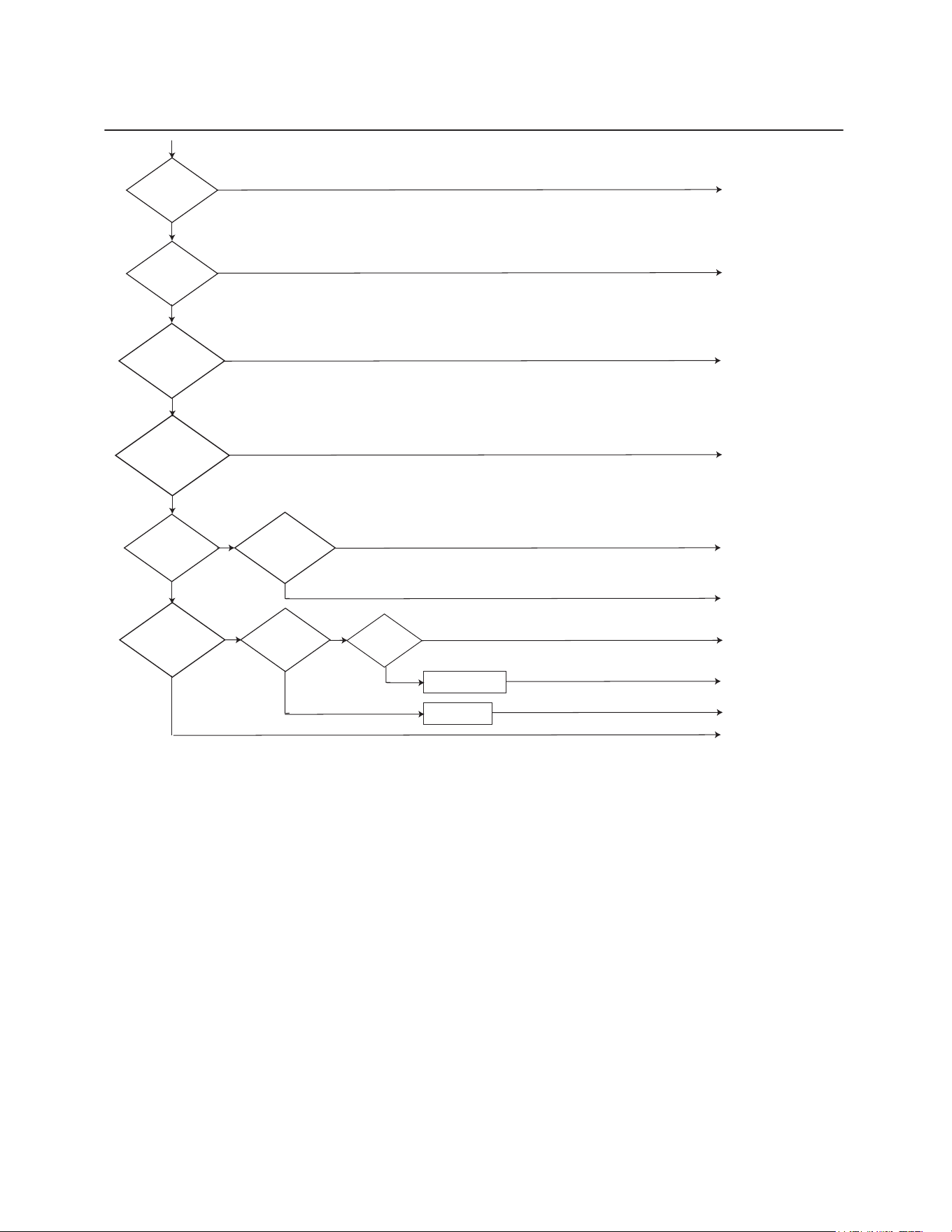
46
Troubleshooting Heat Pump - Heating (2 Stage)
Are refrigerant
pressures and
superheat/subcooling
correct
Verify refrigerant charge
Yes
No
Pressure test, evacuate and
recharge system
Pressure test, evacuate and
recharge system
Check for
leak in
refrigerant
system
Yes
No
Check for
restriction in
system
Yes
Check for restriction
or defective TXV
Repair Leak
No
Second stage heating operating
Yes
Check thermostat & wiring
Is there 24v at
compressor relay
coil?
No
Yes
Yes
Are relay
contacts closed?
Should read 0v at
pins 2 & 4
No
Replace relay
Is there 18-28vdc
at compressor
unloader plug
harness?
No
Yes
Replace unloader plug
Does compressor
change from part load
to full load? Verified
by amp draw
No
Yes
Replace compressor
Yes
Does blower
change to 2nd
stage heating
speed?
No
Check for 24v
between C &
T1/2/3/4/5 terminals
at motor
Check thermostat and wiring or
motor controller
Yes
Check blower motor
No

47
TROUBLESHOOTING
Decommissioning
Before carrying out this procedure, it is essential that the
technician is completely familiar with the equipment and
all its detail. It is recommended good practice that all
refrigerants are recovered safely. Prior to the task being
carried out, an oil and refrigerant sample shall be taken
in case analysis is required prior to re-use of recovered
refrigerant. It is essential that electrical power is available
before the task is commenced.
1. Become familiar with the equipment and its operation.
2. Isolate the system electrically.
3. Before attempting the procedure, ensure that:
A. Mechanical handling equipment is available, if
required, for handling refrigerant cylinders;
B. All personal protective equipment is available and
being used correctly;
C. The recovery process is supervised at all times by
a competent person;
D. Recovery equipment and cylinders conform to the
appropriate standards.
4. Pump down refrigerant system, if possible.
5. If a vacuum is not possible, make a manifold so that
refrigerant can be removed from various parts of the
system.
6. Make sure that cylinder is situated on the scales
before recovery takes place.
7. Start the recovery machine and operate in accordance
with instructions.
8. Do not overll cylinders (no more than 80 % volume
liquid charge).
9. Do not exceed the maximum working pressure of the
cylinder, even temporarily.
10. When the cylinders have been lled correctly and the
process completed, make sure that the cylinders and
the equipment are removed from site promptly and all
isolation valves on the equipment are closed o.
11. Recovered refrigerant shall not be charged into
another REFRIGERATING SYSTEM unless it has
been cleaned and checked.
12. Upon completion of reclaiming the refrigerant.
Authorized personnel may proceed with the removal
of the unit.
Equipment shall be labeled stating that it has been de-
commissioned and emptied of refrigerant. The label
shall be dated and signed. For appliances containing
FLAMMABLE REFRIGERANTS, ensure that there are
labels on the equipment stating the equipment contains
FLAMMABLE REFRIGERANT".
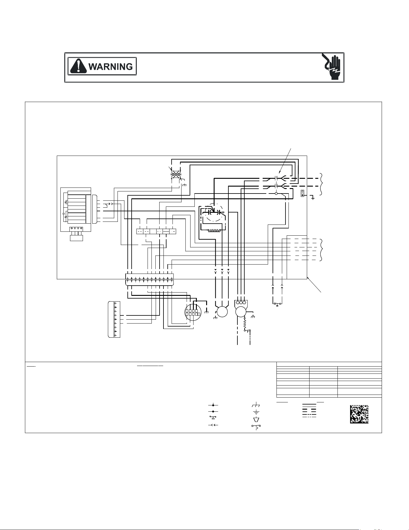
WIRING DIAGRAMS
Wiring is subject to change. Always refer to the wiring diagram on the unit for the most up-to-date wiring.
48
HIGH VOLTAGE!
D
ISCONNECT
ALL
POWER
BEFORE
SERVICING
OR
INSTALLING
THIS
UNIT
.
M
ULTIPLE
POWER
SOURCES
MAY
BE
PRESENT
. F
AILURE
TO
DO
SO
MAY
CAUSE
PROPERTY
DAMAGE
,
PERSONAL
INJURY
OR
DEATH
.
GPCM3[24-60]31
240V
CONTROL BOX
RD
BL
GR
WH
BR
R
C
W2
W1
G
Y
SEE NOTE 3
SEE NOTE 5
LVJB
YL
COMP
S C R
THERMOSTAT
BK
BK
CH & CHS OPTIONAL
@ L1,L2, SEE NOTE 6
0140G04682-A
SEE NOTE 1
BLACK
BLUE
BROWN
GREEN
GRAY
PINK
PURPLE
RED
WHITE
YELLOW
BLUE/PINK STRIPE
HIGH VOLTAGE
WIRING
LOW VOLTAGE
FIELD INSTALLED POWER
FIELD INSTALLED CONTROL
OPTIONAL HIGH VOLTAGE
OPTIONAL LOW VOLTAGE
SEE NOTE 7
RD
BK
BKPU
PU
BK
YL
BL
YL
RD
BK
YL
YL
LVTB
CM
BR
BK
PU
WH
BL BL
WH
BL/PK
BL/PK
GND
LINE
VOLTAGE
208V/230V/1PH/60Hz
SA
SEE NOTE 4
RD
HPS
BL
BL
WH BR
YL GRGY
BL
BL
9
8
7
6
5
4
3
2
1
9
8
7
6
5
4
3
2
1
12
11
10
9
8
7
6
5
4
3
2
1
9
8
7
6
5
4
3
2
1
12
11
10
C L G N
1
2 3
BM
4
5
SEE NOTE 2
GR
BL
PU
BK
GR
BL
BL
BR
WH
BRWH
YL
GR
YL
WH
WH
TR
BL
BL
GR
PK
COM
F
A
N
H
E
R
M
C
O
M
RC
RD
YL
BR
PU
YL
RD
BL
PK
RD
RDS
PLM1
RDS
EEV/10V_IN
EEV/10V_OUT
CTM/OD_OUT
R_ID_OUT
COM
COM
24VAC
1
2
3
4
5
6
7
8
1
2
3
4
5
6
7
8
NOT USED
1
C
5V 2
PORT1
R32
SENSOR
ALARM
WH
GY
GY
CC
T1
T2
L1
L2
BK
PU
PU
BK
BK
RD
YL
BA
C
D
BL
GY
LEAK DETECTION SYSTEM INSTALLED. UNIT MUST BE POWERED EXCEPT FOR SERVICE. SEE USER MANUAL
FOR MORE DETAILS.
RED LED'S STATUS
MODE CHECK
1 FLASH STARTUP MODE -
SLOW LED FLASHING NORMAL OPERATION -
FAST LED FLASHING R-32 LEAK ALARM
LEAK DETECTED. FIND AND REPAIR THE
SOURCE OF THE LEAK.
LED ON CONTINUOUSLY
DELAY MODE
MODE WILL CLEAR AFTER 5 MINUTES.
FAST LED FLASHING
SYSTEM VERIFICATION
MODE
USER ACTIVATED TEST MODE.
2 FLASHES INTERNAL FAULT
REPLACE CONTROL BOARD.
3 FLASHES
R-32 SENSOR
COMMUNICATION FAULT
VERIFY REFRIGERANT SENSOR WIRING.
REPLACE SENSOR. REPLACE CONTROL
BOARD.
4 FLASHES R-32 SENSOR FAULT
REPLACE SENSOR.
BM BLOWER MOTOR
CC COMPRESSOR CONTACTOR
CH CRANKCASE HEATER
CHS CRANKCASE HEATER SWITCH
CM CONDENSER MOTOR
COMP COMPRESSOR
EHK ELECTRIC HEATER KIT
GND EQUIPMENT GROUND
HPS HIGH PRESSURE SWITCH
LVJB LOW VOLTAGE JUNCTION BOX
WIRE CODE
BK
BL
BR
GR
GY
PK
PU
RD
WH
YL
BL/PK
COMPONENT LEGEND
LVTB LOW VOLTAGE TERMINAL BLOCK
PLF FEMALE PLUG/CONNECTOR
PLM MALE PLUG/CONNECTOR
RC RUN CAPACITOR
RDS REFRIGERANT DETECTION SYSTEM
SA START ASSIST
TR TRANSFORMER
BL BK PU
EHK
PLF
EHK
PLM
PLF
PLM
GR
A1A2
BR
BK
PU
BR
BK
PU
NOT
E
S
:
1. REPLACEMENT WIRE MUST BE SAME SIZE AND TYPE OF INSULATION AS ORIGINAL
(AT LEAST 105°C). USE COPPER CONDUCTORS ONLY. USE NEC CLASS 2 WIRE FOR
ALL LOW VOLTAGE FIELD CONNECTIONS.
2. TO CHANGE BLOWER MOTOR SPEED MOVE YELLOW AND WHITE LEADS FROM BM
"2" AND "3" TO "4" AND "5". IF BOTH LEADS ARE ENERGIZED, THE HIGHER SPEED
SETTING IS USED.
3. FOR 208 VOLT TRANSFORMER OPERATION MOVE BLACK WIRE FROM TERMINAL 3
TO TERMINAL 2 ON TRANSFORME
R.
4. START ASSIST FACTORY EQUIPPED WHEN REQUIRED
5. USE COPPER CONDUCTORS ONLY USE N.E.C. CLASS 2 WIRE
6. CRANKCASE HEATER (OPTIONAL)
7. DOUBLE POLE CONTACTOR SHOWN. SINGLE POLE CONTACTOR COULD BE
FACTORY EQUIPPED AS AN ALTERNATE CONFIGURATION.
SEE UNIT RATING PLATE FOR TYPE AND SIZE OF OVER CURRENT PROTECTION
EQUIPMENT GROUND
FIELD GROUND
FIELD SPLICE
SWITCH (TE
MP)
CONNECTOR
JUNCTION
TERMINAL
SWITCH (PRESS.)
WH
GR
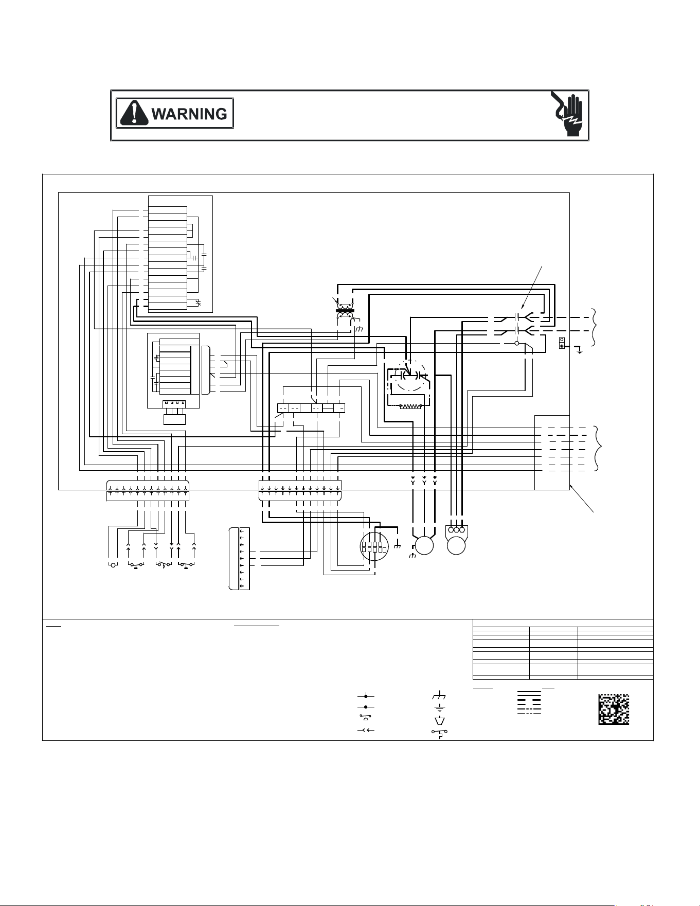
WIRING DIAGRAMS
Wiring is subject to change. Always refer to the wiring diagram on the unit for the most up-to-date wiring.
49
HIGH VOLTAGE!
D
ISCONNECT
ALL
POWER
BEFORE
SERVICING
OR
INSTALLING
THIS
UNIT
.
M
ULTIPLE
POWER
SOURCES
MAY
BE
PRESENT
. F
AILURE
TO
DO
SO
MAY
CAUSE
PROPERTY
DAMAGE
,
PERSONAL
INJURY
OR
DEATH
.
*PHM3[24-42]31
240V
CONTROL BOX
RD
BL
GR
WH
BR
R
C
W2
W1
G
SEE NOTE 3
LVJB
COMP
S
C R
THERMOSTAT
0140G04671-A
SEE NOTE 1
BLACK
BLUE
BROWN
GREEN
GRAY
ORANGE
PINK
PURPLE
RED
WHITE
YELLOW
BLUE/PINK STRIPE
HIGH VOLTAGE
WIRING
LOW VOLTAGE
FIELD INSTALLED POWER
FIELD INSTALLED CONTROL
OPTIONAL HIGH VOLTAGE
OPTIONAL LOW VOLTAGE
SEE NOTE 7
RD
BK
BKPU
PU
BK
YL
BL
YL RD
BK
LVTB
CM
BR
BK
PU
WH
BL
BL
WH
GND
LINE
VOLTAGE
208V/230V/1PH/60Hz
SA
SEE NOTE 4
RD
BL
BL
WH BR
YL GRGY
BL
BL
9
8
7
6
5
4
3
2
1
9
8
7
6
5
4
3
2
1
12
11
10
9
8
7
6
5
4
3
2
1
9
8
7
6
5
4
3
2
1
12
11
10
C L G
N
1 2
3
BM
4 5
SEE NOTE 2
GR
BL
PU
BK
GR
BL
BL
BR
WH
BRWH
YL
GR
YL
WH
WH
TR
BL
BL
GR
PK
COM
F H
C
O
M
RC
RD
YL
BR
PU
YL
RD
BL
PK
RD
RDS
PLM1
RDS
EEV/10V_IN
EEV/10V_OUT
CTM/OD_OUT
R_ID_OUT
COM
COM
24VAC
1
2
3
4
5
6
7
8
1
2
3
4
5
6
7
8
NOT USED
1 C
5V 2
PORT1
R32
SENSOR
ALARM
WH
GY
GY
CC
T1
T2
L1
L2
BK
PU
PU
BK
BK
RD
BA C
D
BL
WH
GY
LEAK DETECTION SYSTEM INSTALLED. UNIT MUST BE POWERED EXCEPT FOR SERVICE. SEE USER MANUAL
FOR MORE DETAILS.
RED LED'S STATUS MODE CHECK
1 FLASH STARTUP MODE
-
SLOW LED FLASHING
NORMAL OPERATION -
FAST LED FLASHING R-32 LEAK ALARM
LEAK DETECTED. FIND AND REPAIR THE
SOURCE OF THE LEAK.
LED ON CONTINUOUSLY
DELAY MODE
MODE WILL CLEAR AFTER 5 MINUTES.
FAST LED FLASHING
SYSTEM VERIFICATION
MODE
USER ACTIVATED TEST MODE.
2 FLASHES INTERNAL FAULT
REPLACE CONTROL BOARD.
3 FLASHES
R-32 SENSOR
COMMUNICATION FAULT
VERIFY REFRIGERANT SENSOR WIRING.
REPLACE SENSOR. REPLACE CONTROL
BOARD.
4 FLASHES
R-32 SENSOR FAULT
REPLACE SENSOR.
BM BLOWER MOTOR
CC COMPRESSOR CONTACTOR
CH CRANKCASE HEATER
CHS CRANKCASE HEATER SWITCH
CM CONDENSER MOTOR
COMP COMPRESSOR
CS COMP SOLENOID (2ND STG COOLING)
DFT DEFROST THERMOSTAT
ECON ECONOMIZER
EHK ELECTRIC HEATER KIT
GND EQUIPMENT GROUND
HPS HIGH PRESSURE SWITCH
WIRE CODE
BK
BL
BR
GR
GY
OR
PK
PU
RD
WH
YL
BL/PNK
CO
MPONENT LEG
END
LPS LOW PRESSURE SWITCH
LVJB LOW VOLTAGE JUNCTION BOX
LVTB LOW VOLTAGE TERMINAL BLOCK
OWV ONE WAY VALVE
PLF FEMALE PLUG/CONNECTOR
PLM MALE PLUG/CONNECTOR
RC RUN CAPACITOR
RDS REFRIGERANT DETECTION SYSTEM
RVC REVERSING VALVE COIL
SA START ASSIST
TR TRANSFORMER
BL BK
PU
EHK
PLF
EHK
PLM
PLF
PLM
PLF
PLM
12
11
10
9
8
7
6
5
4
3
2
1
9
8
7
6
5
4
3
2
1
12
11
10
O-RV
R-PS1
R-DFT
PS2
R
O
C-RV
C
C
DFT
DF1
DF2
PCB
W
CNT
Y
DEFROST CONTROL
PU
PUBR
BR
YLYLBKBK
PU
PU
BK
BK
BR
BR
YL
YL
OR
O
SEE NOTE 5
OR
PU
Y
WH
PU
WH
BL
RD
RD
BL
RD
RD
PU
BR
BK
PU
BR
BK
PU
DFT
BL/PKBL/PK
HPS
BR
LPS
YL/PK
YL/PK
RVC
BR
BK
BK
PU
PUBR
YL
YL
BRBK
BK
GR
A1A2
EQUIPMENT GROUND
FIELD GROUND
FIELD SPLICE
SWITCH (TEMP)
CONNECTOR
JUNCTION
TERMINAL
SWITCH (PRESS.)
NOTES
:
1. REPLACEMENT WIRE MUST BE SAME SIZE AND TYPE OF INSULATION AS ORIGINAL
(AT LEAST 105°C). USE COPPER CONDUCTORS ONLY. USE NEC CLASS 2 WIRE FOR
ALL LOW VOLTAGE FIELD CONNECTIONS.
2. TO CHANGE BLOWER MOTOR SPEED MOVE YELLOW AND WHITE LEADS FROM BM
"2" AND "3" TO "4" AND "5". IF BOTH LEADS ARE ENERGIZED, THE HIGHER SPEED
SETTING IS USED.
3. FOR 208 VOLT TRANSFORMER OPERATION MOVE BLACK WIRE FROM TERMINAL 3
TO TERMINAL 2 ON TRANSFORME
R.
4. START ASSIST FACTORY EQUIPPED WHEN REQUIRED
5. USE COPPER CONDUCTORS ONLY USE N.E.C. CLASS 2 WIRE
6. CRANKCASE HEATER (OPTIONAL)
7. DOUBLE POLE CONTACTOR SHOWN. SINGLE POLE CONTACTOR COULD BE
FACTORY EQUIPPED AS AN ALTERNATE CONFIGURATION.
SEE UNIT RATING PLATE FOR TYPE AND SIZE OF OVER CURRENT PROTECTION
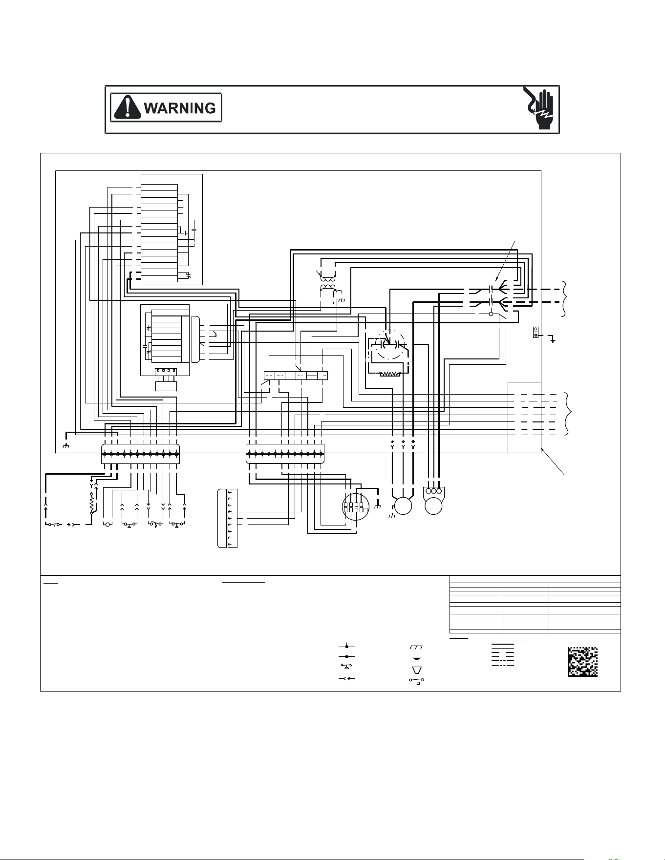
WIRING DIAGRAMS
Wiring is subject to change. Always refer to the wiring diagram on the unit for the most up-to-date wiring.
50
HIGH VOLTAGE!
D
ISCONNECT
ALL
POWER
BEFORE
SERVICING
OR
INSTALLING
THIS
UNIT
.
M
ULTIPLE
POWER
SOURCES
MAY
BE
PRESENT
. F
AILURE
TO
DO
SO
MAY
CAUSE
PROPERTY
DAMAGE
,
PERSONAL
INJURY
OR
DEATH
.
*PHM34831
240V
CONTROL BOX
RD
BL
GR
WH
BR
R
C
W2
W1
G
SEE NOTE 3
LVJB
COMP
S
C R
THERMOSTAT
0140G04686-A
SEE NOTE 1
BLACK
BLUE
BROWN
GREEN
GRAY
ORANGE
PINK
PURPLE
RED
WHITE
YELLOW
YELLOW/PINK STRIPE
BLUE/PINK STRIPE
TAN
HIGH VOLTAGE
WIRING
LOW VOLTAGE
FIELD INSTALLED POWER
FIELD INSTALLED CONTROL
OPTIONAL HIGH VOLTAGE
OPTIONAL LOW VOLTAGE
SEE NOTE 7
RD
BK
BKPU
PU
BK
YL
BR
BL
YL RD
BK
LVTB
CM
BR
BK
PU
WH
BL
BL
WH
GND
LINE
VOLTAGE
208V/230V/1PH/60Hz
SA
SEE NOTE 4
RD
BL
BL
WH BR
YL GRGY
BL
BL
9
8
7
6
5
4
3
2
1
9
8
7
6
5
4
3
2
1
12
11
10
9
8
7
6
5
4
3
2
1
9
8
7
6
5
4
3
2
1
12
11
10
C L G
N
1 2
3
BM
4 5
SEE NOTE 2
GR
BL
PU
BK
GR
BL
BL
BR
WH
BRWH
YL
GR
YL
WH
WH
TR
BL
BL
GR
PK
COM
F H
C
O
M
RC
RD
YL
BR
PU
YL
RD
BL
PK
RD
RDS
PLM1
RDS
EEV/10V_IN
EEV/10V_OUT
CTM/OD_OUT
R_ID_OUT
COM
COM
24VAC
1
2
3
4
5
6
7
8
1
2
3
4
5
6
7
8
NOT USED
1 C
5V 2
PORT1
R32
SENSOR
ALARM
WH
GY
GY
CC
T1
T2
L1
L2
BK
PU
PU
BK
BK
RD
BA C
D
BL
WH
GY
LEAK DETECTION SYSTEM INSTALLED. UNIT MUST BE POWERED EXCEPT FOR SERVICE. SEE USER MANUAL
FOR MORE DETAILS.
RED LED'S STATUS MODE CHECK
1 FLASH STARTUP MODE
-
SLOW LED FLASHING
NORMAL OPERATION -
FAST LED FLASHING R-32 LEAK ALARM
LEAK DETECTED. FIND AND REPAIR THE
SOURCE OF THE LEAK.
LED ON CONTINUOUSLY
DELAY MODE
MODE WILL CLEAR AFTER 5 MINUTES.
FAST LED FLASHING
SYSTEM VERIFICATION
MODE
USER ACTIVATED TEST MODE.
2 FLASHES INTERNAL FAULT
REPLACE CONTROL BOARD.
3 FLASHES
R-32 SENSOR
COMMUNICATION FAULT
VERIFY REFRIGERANT SENSOR WIRING.
REPLACE SENSOR. REPLACE CONTROL
BOARD.
4 FLASHES
R-32 SENSOR FAULT
REPLACE SENSOR.
BM BLOWER MOTOR
CC COMPRESSOR CONTACTOR
CH CRANKCASE HEATER
CHS CRANKCASE HEATER SWITCH
CM CONDENSER MOTOR
COMP COMPRESSOR
DFT DEFROST THERMOSTAT
ECON ECONOMIZER
EHK ELECTRIC HEATER KIT
GND EQUIPMENT GROUND
HPS HIGH PRESSURE SWITCH
LPS LOW PRESSURE SWITCH
WIRE CODE
BK
BL
BR
GR
GY
OR
PK
PU
RD
WH
YL
YL/PK
BL/PK
TN
CO
MPONENT LEG
END
LVJB LOW VOLTAGE JUNCTION BOX
LVTB LOW VOLTAGE TERMINAL BLOCK
PLF FEMALE PLUG/CONNECTOR
PLM MALE PLUG/CONNECTOR
RC RUN CAPACITOR
RDS REFRIGERANT DETECTION SYSTEM
RVC REVERSING VALVE COIL
SA START ASSIST
TR TRANSFORMER
BL BK PU
EHK
PLF
EHK
PLM
PLF
PLM
PLF
PLM
12
11
10
9
8
7
6
5
4
3
2
1
9
8
7
6
5
4
3
2
1
12
11
10
O-RV
R-PS1
R-DFT
PS2
R
O
C-RV
C
C
DFT
DF1
DF2
PCB
W
CNT
Y
DEFROST CONTROL
PU
PUBR
BR
YLYLBKBK
PU
PU
BK
BK
BR
BR
YL
YL
OR
O
SEE NOTE 5
OR
PU
Y
WH
PU
WH
BL
RD
RD
BL
RD
RD
PU
BR
BK
PU
BR
BK
PU
DFT
BL/PKBL/PK
HPS
BR
LPS
YL/PK
YL/PK
RVC
BR
BK
BK
PU
PUBR
YL
YL
BRBK
BK
PU
BK GR
CHS
RD
CH
GR
RD
BK
BK
PU
GR
BKPU
BK
PU
GR
GR
A1A2
NOT
E
S
:
1. REPLACEMENT WIRE MUST BE SAME SIZE AND TYPE OF INSULATION AS ORIGINAL
(AT LEAST 105°C). USE COPPER CONDUCTORS ONLY. USE NEC CLASS 2 WIRE FOR
ALL LOW VOLTAGE FIELD CONNECTIONS.
2. TO CHANGE BLOWER MOTOR SPEED MOVE YELLOW AND WHITE LEADS FROM BM
"2" AND "3" TO "4" AND "5". IF BOTH LEADS ARE ENERGIZED, THE HIGHER SPEED
SETTING IS USED.
3. FOR 208 VOLT TRANSFORMER OPERATION MOVE BLACK WIRE FROM TERMINAL 3
TO TERMINAL 2 ON TRANSFORME
R.
4. START ASSIST FACTORY EQUIPPED WHEN REQUIRED
5. USE COPPER CONDUCTORS ONLY USE N.E.C. CLASS 2 WIRE
6. CRANKCASE HEATER (OPTIONAL)
7. DOUBLE POLE CONTACTOR SHOWN. SINGLE POLE CONTACTOR COULD BE
FACTORY EQUIPPED AS AN ALTERNATE CONFIGURATION.
SEE UNIT RATING PLATE FOR TYPE AND SIZE OF OVER CURRENT PROTECTION
EQUIP
MENT GROUND
FIELD GROUND
FIELD SPLICE
SWITCH (TEMP)
CONNECTOR
JUNCTION
TERMINAL
SWITCH (PRESS.)
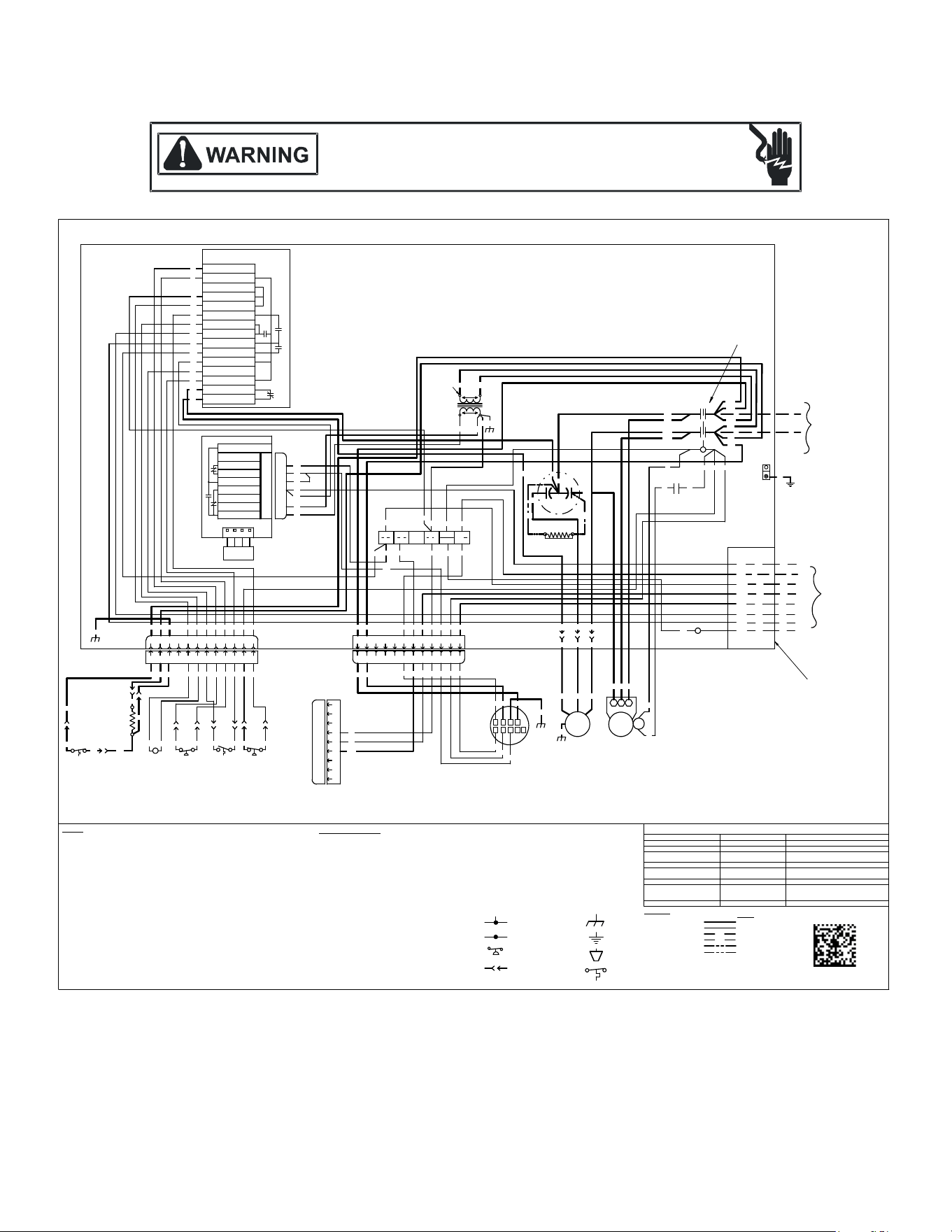
WIRING DIAGRAMS
Wiring is subject to change. Always refer to the wiring diagram on the unit for the most up-to-date wiring.
51
HIGH VOLTAGE!
D
ISCONNECT
ALL
POWER
BEFORE
SERVICING
OR
INSTALLING
THIS
UNIT
.
M
ULTIPLE
POWER
SOURCES
MAY
BE
PRESENT
. F
AILURE
TO
DO
SO
MAY
CAUSE
PROPERTY
DAMAGE
,
PERSONAL
INJURY
OR
DEATH
.
*PHM36031
240V
CONTROL BOX
RD
BL
GR
WH
BR
R
C
W2
W1
G
SEE NOTE 3
LVJB
COMP
S
C R
THERMOSTAT
0140G04678-A
SEE NOTE 1
HIGH VOLTAGE
WIRING
LOW VOLTAGE
FIELD INSTALLED POWER
FIELD INSTALLED CONTROL
OPTIONAL HIGH VOLTAGE
OPTIONAL LOW VOLTAGE
SEE NOTE 7
RD
BK
BKPU
PU
BK
YL
YL RD
BK
LVTB
CM
BR
BK
PU
WH
BL
BL
WH
GND
LINE
VOLTAGE
208V/230V/1PH/60Hz
SA
SEE NOTE 4
RD
BL
BL
WH BR
YL GRGY
BL
BL
9
8
7
6
5
4
3
2
1
9
8
7
6
5
4
3
2
1
12
11
10
9
8
7
6
5
4
3
2
1
9
8
7
6
5
4
3
2
1
12
11
10
C L G
N
1 2
3
BM
4 5
SEE NOTE 2
GR
BL
PU
BK
GR
BL
BL
BR
WH
BRWH
YL
GR
YL
WH
WH
TR
BL
BL
GR
PK
COM
F H
C
O
M
RC
RD
YL
BR
PU
YL
RD
BL
PK
RD
RDS
PLM1
RDS
EEV/10V_IN
EEV/10V_OUT
CTM/OD_OUT
R_ID_OUT
COM
COM
24VAC
1
2
3
4
5
6
7
8
1
2
3
4
5
6
7
8
NOT USED
1 C
5V 2
PORT1
R32
SENSOR
ALARM
WH
GY
GY
CC
T1
T2
L1
L2
BK
PU
PU
BK
BK
RD
BA C
D
BL
WH
GY
LEAK DETECTION SYSTEM INSTALLED. UNIT MUST BE POWERED EXCEPT FOR SERVICE. SEE USER MANUAL
FOR MORE DETAILS.
RED LED'S STATUS MODE CHECK
1 FLASH STARTUP MODE
-
SLOW LED FLASHING
NORMAL OPERATION -
FAST LED FLASHING R-32 LEAK ALARM
LEAK DETECTED. FIND AND REPAIR THE
SOURCE OF THE LEAK.
LED ON CONTINUOUSLY
DELAY MODE
MODE WILL CLEAR AFTER 5 MINUTES.
FAST LED FLASHING
SYSTEM VERIFICATION
MODE
USER ACTIVATED TEST MODE.
2 FLASHES INTERNAL FAULT
REPLACE CONTROL BOARD.
3 FLASHES
R-32 SENSOR
COMMUNICATION FAULT
VERIFY REFRIGERANT SENSOR WIRING.
REPLACE SENSOR. REPLACE CONTROL
BOARD.
4 FLASHES
R-32 SENSOR FAULT
REPLACE SENSOR.
BM BLOWER MOTOR
CC COMPRESSOR CONTACTOR
CH CRANKCASE HEATER
CHS CRANKCASE HEATER SWITCH
CM CONDENSER MOTOR
COMP COMPRESSOR
CSR COMPRESSOR SOLENOID RELAY
DFT DEFROST THERMOSTAT
ECON ECONOMIZER
EHK ELECTRIC HEATER KIT
GND EQUIPMENT GROUND
HPS HIGH PRESSURE SWITCH
LPS LOW PRESSURE SWITCH
CO
MPONENT LEG
END
LVJB LOW VOLTAGE JUNCTION BOX
LVTB LOW VOLTAGE TERMINAL BLOCK
PLF FEMALE PLUG/CONNECTOR
PLM MALE PLUG/CONNECTOR
RC RUN CAPACITOR
RDS REFRIGERANT DETECTION SYSTEM
RVC REVERSING VALVE COIL
SA START ASSIST
SOL SOLENOID
TR TRANSFORMER
BL BK PU
EHK
PLF
EHK
PLM
PLF
PLM
PLF
PLM
12
11
10
9
8
7
6
5
4
3
2
1
9
8
7
6
5
4
3
2
1
12
11
10
O-RV
R-PS1
R-DFT
PS2
R
O
C-RV
C
C
DFT
DF1
DF2
PCB
W
CNT
Y
DEFROST CONTROL
PU
PUBR
BR
YLYLBKBK
PU
PU
BK
BK
BR
BR
YL
YL
OR
O
SEE NOTE 5
OR
PU
Y1
WH
PU
WH
BL
RD
RD
BL
RD
RD
PU
Y2
YL
CSR
13
BL
BL
YL
2
CSR
4
SOL
BL
YL
YL
YL
BL
BLACK
BLUE
BROWN
GREEN
GRAY
ORANGE
PINK
PURPLE
RED
WHITE
YELLOW
YELLOW/PINK STRIPE
BLUE/PINK STRIPE
TAN
WIRE COD
E
BK
BL
BR
GR
GY
OR
PK
PU
RD
WH
YL
YL/PK
BL/PK
TN
DFT
BL/PK
BL/PK
HPS
BR
LPS
YL/PK
YL/PK
RVC
BR
BK
BK
PU
PUBRYL
YL
BRBK
BK
PU BK
GR
CHS
RD
CH
GR
RD
BK
BK
PU
GR
BKPU
GR
BK
PU
GR
A1
A2
BR
BK
PU
BR
BK
PU
NOT
E
S:
1. REPLACEMENT WIRE MUST BE SAME SIZE AND TYPE OF INSULATION AS ORIGINAL
(AT LEAST 105°C). USE COPPER CONDUCTORS ONLY. USE NEC CLASS 2 WIRE FOR
ALL LOW VOLTAGE FIELD CONNECTIONS.
2. TO CHANGE BLOWER MOTOR SPEED MOVE YELLOW AND WHITE LEADS FROM BM
"2" AND "3" TO "4" AND "5". IF BOTH LEADS ARE ENERGIZED, THE HIGHER SPEED
SETTING IS USED.
3. FOR 208 VOLT TRANSFORMER OPERATION MOVE BLACK WIRE FROM TERMINAL 3
TO TERMINAL 2 ON TRANSFORME
R.
4. START ASSIST FACTORY EQUIPPED WHEN REQUIRED
5. USE COPPER CONDUCTORS ONLY USE N.E.C. CLASS 2 WIRE
6. CRANKCASE HEATER (OPTIONAL)
7. DOUBLE POLE CONTACTOR SHOWN. SINGLE POLE CONTACTOR COULD BE
FACTORY EQUIPPED AS AN ALTERNATE CONFIGURATION.
SEE UNIT RATING PLATE FOR TYPE AND SIZE OF OVER CURRENT PROTECTION
EQUIPMENT GROUND
FIELD GROUND
FIELD SPLICE
SWITCH (TEMP)
CONNECTOR
JUNCTION
TERMINAL
SWITCH (PRESS.)
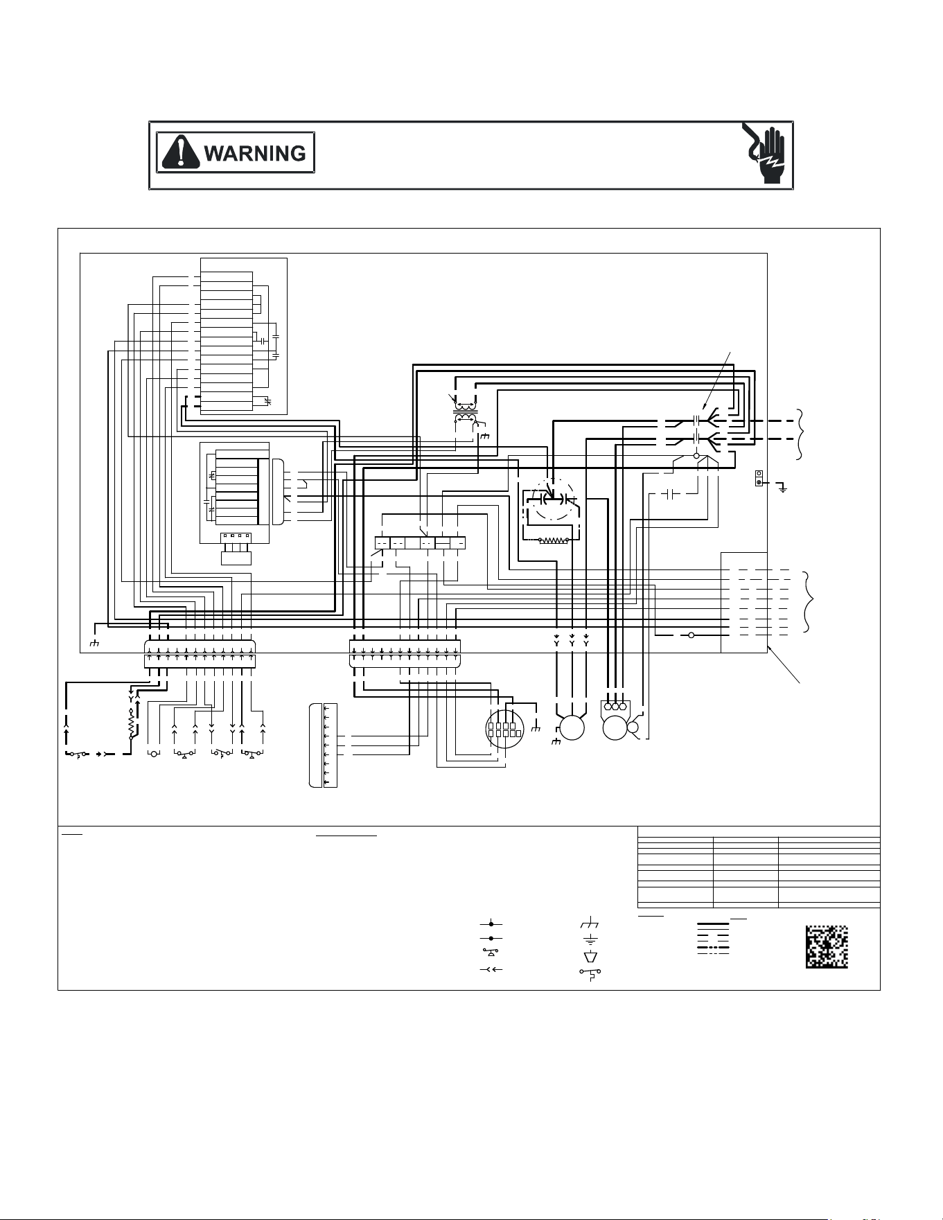
WIRING DIAGRAMS
Wiring is subject to change. Always refer to the wiring diagram on the unit for the most up-to-date wiring.
52
HIGH VOLTAGE!
D
ISCONNECT
ALL
POWER
BEFORE
SERVICING
OR
INSTALLING
THIS
UNIT
.
M
ULTIPLE
POWER
SOURCES
MAY
BE
PRESENT
. F
AILURE
TO
DO
SO
MAY
CAUSE
PROPERTY
DAMAGE
,
PERSONAL
INJURY
OR
DEATH
.
GPHM5(24-48)31
240V
CONTROL BOX
RD
BL
GR
WH
BR
R
C
W2
W1
G
SEE NOTE 3
LVJB
COMP
S
C R
THERMOSTAT
0140G04678-A
SEE NOTE 1
HIGH VOLTAGE
WIRING
LOW VOLTAGE
FIELD INSTALLED POWER
FIELD INSTALLED CONTROL
OPTIONAL HIGH VOLTAGE
OPTIONAL LOW VOLTAGE
SEE NOTE 7
RD
BK
BKPU
PU
BK
YL
YL RD
BK
LVTB
CM
BR
BK
PU
WH
BL
BL
WH
GND
LINE
VOLTAGE
208V/230V/1PH/60Hz
SA
SEE NOTE 4
RD
BL
BL
WH BR
YL GRGY
BL
BL
9
8
7
6
5
4
3
2
1
9
8
7
6
5
4
3
2
1
12
11
10
9
8
7
6
5
4
3
2
1
9
8
7
6
5
4
3
2
1
12
11
10
C L G
N
1 2
3
BM
4 5
SEE NOTE 2
GR
BL
PU
BK
GR
BL
BL
BR
WH
BRWH
YL
GR
YL
WH
WH
TR
BL
BL
GR
PK
COM
F H
C
O
M
RC
RD
YL
BR
PU
YL
RD
BL
PK
RD
RDS
PLM1
RDS
EEV/10V_IN
EEV/10V_OUT
CTM/OD_OUT
R_ID_OUT
COM
COM
24VAC
1
2
3
4
5
6
7
8
1
2
3
4
5
6
7
8
NOT USED
1 C
5V 2
PORT1
R32
SENSOR
ALARM
WH
GY
GY
CC
T1
T2
L1
L2
BK
PU
PU
BK
BK
RD
BA C
D
BL
WH
GY
LEAK DETECTION SYSTEM INSTALLED. UNIT MUST BE POWERED EXCEPT FOR SERVICE. SEE USER MANUAL
FOR MORE DETAILS.
RED LED'S STATUS MODE CHECK
1 FLASH STARTUP MODE
-
SLOW LED FLASHING
NORMAL OPERATION -
FAST LED FLASHING R-32 LEAK ALARM
LEAK DETECTED. FIND AND REPAIR THE
SOURCE OF THE LEAK.
LED ON CONTINUOUSLY
DELAY MODE
MODE WILL CLEAR AFTER 5 MINUTES.
FAST LED FLASHING
SYSTEM VERIFICATION
MODE
USER ACTIVATED TEST MODE.
2 FLASHES INTERNAL FAULT
REPLACE CONTROL BOARD.
3 FLASHES
R-32 SENSOR
COMMUNICATION FAULT
VERIFY REFRIGERANT SENSOR WIRING.
REPLACE SENSOR. REPLACE CONTROL
BOARD.
4 FLASHES
R-32 SENSOR FAULT
REPLACE SENSOR.
BM BLOWER MOTOR
CC COMPRESSOR CONTACTOR
CH CRANKCASE HEATER
CHS CRANKCASE HEATER SWITCH
CM CONDENSER MOTOR
COMP COMPRESSOR
CSR COMPRESSOR SOLENOID RELAY
DFT DEFROST THERMOSTAT
ECON ECONOMIZER
EHK ELECTRIC HEATER KIT
GND EQUIPMENT GROUND
HPS HIGH PRESSURE SWITCH
LPS LOW PRESSURE SWITCH
CO
MPONENT LEG
END
LVJB LOW VOLTAGE JUNCTION BOX
LVTB LOW VOLTAGE TERMINAL BLOCK
PLF FEMALE PLUG/CONNECTOR
PLM MALE PLUG/CONNECTOR
RC RUN CAPACITOR
RDS REFRIGERANT DETECTION SYSTEM
RVC REVERSING VALVE COIL
SA START ASSIST
SOL SOLENOID
TR TRANSFORMER
BL BK PU
EHK
PLF
EHK
PLM
PLF
PLM
PLF
PLM
12
11
10
9
8
7
6
5
4
3
2
1
9
8
7
6
5
4
3
2
1
12
11
10
O-RV
R-PS1
R-DFT
PS2
R
O
C-RV
C
C
DFT
DF1
DF2
PCB
W
CNT
Y
DEFROST CONTROL
PU
PUBR
BR
YLYLBKBK
PU
PU
BK
BK
BR
BR
YL
YL
OR
O
SEE NOTE 5
OR
PU
Y1
WH
PU
WH
BL
RD
RD
BL
RD
RD
PU
Y2
YL
CSR
13
BL
BL
YL
2
CSR
4
SOL
BL
YL
YL
YL
BL
BLACK
BLUE
BROWN
GREEN
GRAY
ORANGE
PINK
PURPLE
RED
WHITE
YELLOW
YELLOW/PINK STRIPE
BLUE/PINK STRIPE
TAN
WIRE COD
E
BK
BL
BR
GR
GY
OR
PK
PU
RD
WH
YL
YL/PK
BL/PK
TN
DFT
BL/PK
BL/PK
HPS
BR
LPS
YL/PK
YL/PK
RVC
BR
BK
BK
PU
PUBRYL
YL
BRBK
BK
PU BK
GR
CHS
RD
CH
GR
RD
BK
BK
PU
GR
BKPU
GR
BK
PU
GR
A1
A2
BR
BK
PU
BR
BK
PU
NOT
E
S:
1. REPLACEMENT WIRE MUST BE SAME SIZE AND TYPE OF INSULATION AS ORIGINAL
(AT LEAST 105°C). USE COPPER CONDUCTORS ONLY. USE NEC CLASS 2 WIRE FOR
ALL LOW VOLTAGE FIELD CONNECTIONS.
2. TO CHANGE BLOWER MOTOR SPEED MOVE YELLOW AND WHITE LEADS FROM BM
"2" AND "3" TO "4" AND "5". IF BOTH LEADS ARE ENERGIZED, THE HIGHER SPEED
SETTING IS USED.
3. FOR 208 VOLT TRANSFORMER OPERATION MOVE BLACK WIRE FROM TERMINAL 3
TO TERMINAL 2 ON TRANSFORME
R.
4. START ASSIST FACTORY EQUIPPED WHEN REQUIRED
5. USE COPPER CONDUCTORS ONLY USE N.E.C. CLASS 2 WIRE
6. CRANKCASE HEATER (OPTIONAL)
7. DOUBLE POLE CONTACTOR SHOWN. SINGLE POLE CONTACTOR COULD BE
FACTORY EQUIPPED AS AN ALTERNATE CONFIGURATION.
SEE UNIT RATING PLATE FOR TYPE AND SIZE OF OVER CURRENT PROTECTION
EQUIPMENT GROUND
FIELD GROUND
FIELD SPLICE
SWITCH (TEMP)
CONNECTOR
JUNCTION
TERMINAL
SWITCH (PRESS.)
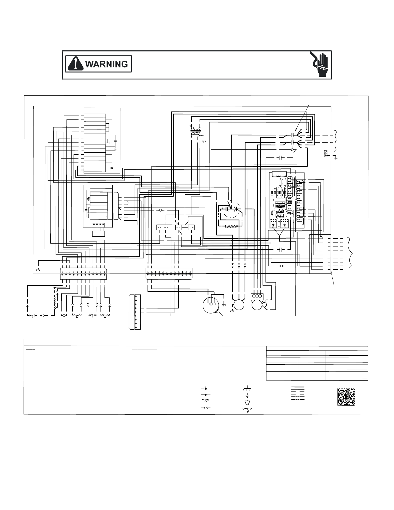
WIRING DIAGRAMS
Wiring is subject to change. Always refer to the wiring diagram on the unit for the most up-to-date wiring.
53
HIGH VOLTAGE!
D
ISCONNECT
ALL
POWER
BEFORE
SERVICING
OR
INSTALLING
THIS
UNIT
.
M
ULTIPLE
POWER
SOURCES
MAY
BE
PRESENT
. F
AILURE
TO
DO
SO
MAY
CAUSE
PROPERTY
DAMAGE
,
PERSONAL
INJURY
OR
DEATH
.
APHM5(24-48)31
CONTROL BOX
RD
BL
GR
WH
BR
R
C
W2
W1
G
LVJB
COMP
S
C R
THERMOSTAT
0140G04672-A
BLACK
BLUE
BROWN
GREEN
GRAY
ORANGE
PINK
PURPLE
RED
WHITE
YELLOW
YELLOW/PINK STRIPE
BLUE/PINK STRIPE
TAN
HIGH VOLTAGE
WIRING
LOW VOLTAGE
FIELD INSTALLED POWER
FIELD INSTALLED CONTROL
OPTIONAL HIGH VOLTAGE
OPTIONAL LOW VOLTAGE
BK
PU
YL
RD
BK
LVTB
CM
BR
BK
PU
WH
BL
BL
WH
SA
SEE NOTE 4
RD
BL
WH
BR
BL
9
8
7
6
5
4
3
2
1
9
8
7
6
5
4
3
2
1
12
11
10
9
8
7
6
5
4
3
2
1
9
8
7
6
5
4
3
2
1
12
11
10
L2
G
L1
BM
PU
BK
GR
BL
BL
BR
WH
BR
WH
F H
C
O
M
RC
RD
YL
BR
PU
YL
RD
BL
PK
RD
RDS
PLM1
RDS
EEV/10V_IN
EEV/10V_OUT
CTM/OD_OUT
R_ID_OUT
COM
COM
24VAC
1
2
3
4
5
6
7
8
1
2
3
4
5
6
7
8
NOT USED
1 C
5V 2
PORT1
R32
SENSOR
ALARM
YL
TN
TN
B
A
C
D
BL
TN
LEAK DETECTION SYSTEM INSTALLED. UNIT MUST BE POWERED EXCEPT FOR SERVICE. SEE USER MANUAL
FOR MORE DETAILS.
RED LED'S STATUS
MODE
CHECK
1 FLASH
STARTUP MODE
-
SLOW LED FLASHING
NORMAL OPERATION
-
FAST LED FLASHING
R-32 LEAK ALARM
LEAK DETECTED. FIND AND REPAIR THE
SOURCE OF THE LEAK.
LED ON CONTINUOUSLY
DELAY MODE
MODE WILL CLEAR AFTER 5 MINUTES.
FAST LED FLASHING
SYSTEM VERIFICATION
MODE
USER ACTIVATED TEST MODE.
2 FLASHES
INTERNAL FAULT
REPLACE CONTROL BOARD.
3 FLASHES
R-32 SENSOR
COMMUNICATION FAULT
VERIFY REFRIGERANT SENSOR WIRING.
REPLACE SENSOR. REPLACE CONTROL
BOARD.
4 FLASHES
R-32 SENSOR FAULT
REPLACE SENSOR.
BM BLOWER MOTOR
CC COMPRESSOR CONTACTOR
CH CRANKCASE HEATER
CHS CRANKCASE HEATER SWITCH
CM CONDENSER MOTOR
COMP COMPRESSOR
CSR COMPRESSOR SOLENOID RELAY
DFT DEFROST THERMOSTAT
ECON ECONOMIZER
EHK ELECTRIC HEATER KIT
GND EQUIPMENT GROUND
HPS HIGH PRESSURE SWITCH
LPS LOW PRESSURE SWITCH
LVJB LOW VOLTAGE JUNCTION BOX
LVTB LOW VOLTAGE TERMINAL BLOCK
WIRE COD
E
BK
BL
BR
GR
GY
OR
PK
PU
RD
WH
YL
YL/PK
BL/PK
TN
CO
M
PONENT LEG
END
PLF FEMALE PLUG/CONNECTOR
PLM MALE PLUG/CONNECTOR
RC RUN CAPACITOR
RDS REFRIGERANT DETECTION SYSTEM
RVC REVERSING VALVE COIL
SA START ASSIST
SOL SOLENOID
TR TRANSFORMER
VSTB VARIABLE SPEED TERMINAL BOARD
VSTBR VARIABLE SPEED TERMINAL BOARD
RELAY
BK
PU
EHK
PLF
EHK
PLM
PLF
PLM
PLF
PLM
12
11
10
9
8
7
6
5
4
3
2
1
9
8
7
6
5
4
3
2
1
12
11
10
O-RV
R-PS1
R-DFT
PS2
R
O
C-RV
C
C
DFT
DF1
DF2
PCB
W
CNT
Y
DEFROST CONTROL
PU
PU
BR
BR
YL
YL
BK
BK
DFT
PU
PU
BK
BK
BR
BR
YL
YL
OR
O
SEE NOTE 5
OR
PU
Y1
WH
PU
WH
BL
RD
BL
RD
RD
PU
BL/PK
BL/PK
HPS
PU
PU
BR
BR
BR
LPS
YL/PK
YL/PK
YL
YL
RVC
BK
BK
BR
BR
BK
PU
BR
BK
PU
BK
BK
Y2
YL
BL
YL
SOL
VSTB
SWITCH
8 7 6 5 4 3 2 1
W1
OT1
OT2
HUM
PJ6
PJ2
PJ4
W2
C
R
9
HEATER
W1 W2 C R
24 VAC
C
R
8
C
R
7
C
R
6
J3
C
R
5
C
2
4
1
J2
C
R
2
DS1
C
R
1
R
5
OFF
ON
DIP
E
F
1
3
A
M
P
C
R
1
0
R
3
PN. PCB00102
(CFM)
CONFIGURATION.
DIP SWITCH
FOR PROPER
TO MANUAL
PLEASE REFER
R
1
R
2
MOC O 2W DER NOCY
HEATPUMP
CONDENSER
OUTDOOR
THERMOSTATS
HUMIDISTAT
HUM2TO C R 1Y G 2Y/YOT12W/W O CTOE\W1
J1
1
Y1
5
GND
GR
GR
BK
PU
240V
SEE NOTE 3
SEE NOTE 1
SEE NOTE 7
RD
BK
PU
BK
LINE
VOLTAGE
208V/230V/1PH/60Hz
TR
BL
GR
PK
COM
CC
T1
T2
L1
L2
BK
PU
PU
BK
BK
RD
PU
BK
2
CSR
4
YL
YL
WH
BR
OR
PU
GR
GY
TN
BR
RD OR
WH
GY
HUM
BL
YL
VSTBR
1
3
BL
RD
RD
BL
BL
BL
BK
2
VSTBR
4
BK
PU
CSR
1
3
BL
YL
PU
BK
GR
CHS
RD
CH
GR
RD
BK
BK
PU
BL
PK
PK
YL
GR
GR
A1
A2
EQUIPMENT GROUND
FIELD GROUND
FIELD SPLICE
SWITCH (TEMP)
CONNECTOR
JUNCTION
TERMINAL
SWITCH (PRESS.)
NOT
E
S
:
1. REPLACEMENT WIRE MUST BE SAME SIZE AND TYPE OF INSULATION AS ORIGINAL
(AT LEAST 105°C). USE COPPER CONDUCTORS ONLY. USE NEC CLASS 2 WIRE FOR
ALL LOW VOLTAGE FIELD CONNECTIONS.
2. TO CHANGE BLOWER MOTOR SPEED MOVE YELLOW AND WHITE LEADS FROM BM
"2" AND "3" TO "4" AND "5". IF BOTH LEADS ARE ENERGIZED, THE HIGHER SPEED
SETTING IS USED.
3. FOR 208 VOLT TRANSFORMER OPERATION MOVE BLACK WIRE FROM TERMINAL 3
TO TERMINAL 2 ON TRANSFORMER.
4. START ASSIST FACTORY EQUIPPED WHEN REQUIRED
5. USE COPPER CONDUCTORS ONLY USE N.E.C. CLASS 2 WIRE
6. CRANKCASE HEATER (OPTIONAL)
7. DOUBLE POLE CONTACTOR SHOWN. SINGLE POLE CONTACTOR COULD BE
FACTORY EQUIPPED AS AN ALTERNATE CONFIGURATION.
SEE UNIT RATING PLATE FOR TYPE AND SIZE OF OVER CURRENT PROTECTION



