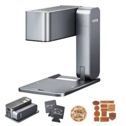
LASER ENGRAVER Prex


Table of Contents
1.FCC Requirement ........................................................................................ 1
2.Laser Engraver Introduction ...................................................................... 5
3.Packing List ................................................................................................. 6
4.Assembly Steps ........................................................................................... 11
5.Machine Calibration ................................................................................... 22
6.Machine Testing .......................................................................................... 24

Any changes or modifications not expressly approved by the party responsible for compliance
could void the user’s authority to operate the equipment.
This device complies with Part 15 of the FCC Rules. Operation is subject to the following two
conditions:
(1) this device may not cause harmful interference, and
(2) this device must accept any interference received, including interference that may cause
undesired operation.
Note:
This equipment has been tested and found to comply with the limits for a Class B digital device,
pursuant to Part 15 of the FCC Rules. These limits are designed to provide reasonable protection
against harmful interference in a residential installation. This equipment generates, uses, and can
radiate radio frequency energy, and if not installed and used in accordance with the instructions,
may cause harmful interference to radio communications. However, there is no guarantee that
interference will not occur in a particular installation. If this equipment does cause harmful
interference to radio or television reception, which can be determined by turning the equipment
off and on, the user is encouraged to try to correct the interference by one or more of the following
measures:
‒ Reorient or relocate the receiving antenna.
‒ Increase the separation between the equipment and receiver.
‒ Connect the equipment into an outlet on a circuit different from that to which the receiver is
connected.
‒ Consult the dealer or an experienced radio/TV technician for help.
FCC Radiation Exposure Statement:
This equipment complies with FCC radiation exposure limits set forth for an uncontrolled
environment. This equipment should be installed and operated with minimum distance 20 cm
between the radiator & your body.
11
FCC Requirement
1. Prex engraves and cuts materials through a high-energy diode laser beam. Hazards associated
with high-energy diode laser beams include causing fires, generating harmful and/or irritating
toxic smoke, but more importantly, damage to the eyes and skin.
2. Laser engravers are classified into several internationally recognized categories based on their
performance and injury risk. Prex belongs to Class IV (IEC standard Class 4 focuses on US FDA
classification).
2
! CAUTION !
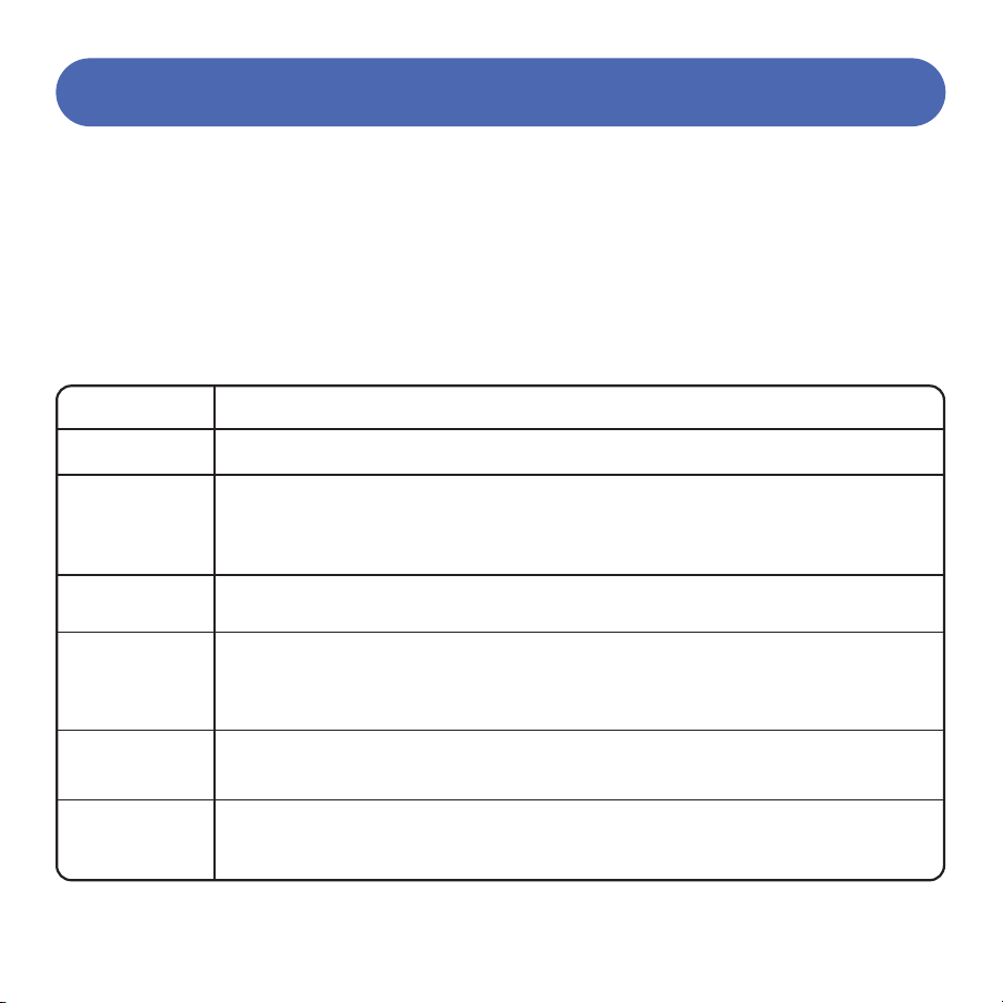
Laser Class
Class Definition
Class I
Class IIa
Class II
Class IIIa
Class IIIb
Class IV
Class I laser radiation levels are not considered hazardous.
Class IIa laser radiation levels are not considered hazardous
for viewing times less than or equal to 1×10³ seconds, but
are considered chronic viewing hazards for viewing times
greater than 1×10³ seconds.
Class II laser radiation levels are considered chronic viewing hazards.
Class IIIa laser radiation levels, depending on irradiance, may be
acute beam-in-the-eye viewing hazards or chronic viewing
hazards; if viewed directly with optical instruments, they are
acute viewing hazards.
Class IIIb laser radiation levels are considered acute direct radiation
hazards to the skin and eyes.
Class IV laser radiation levels are considered acute direct and
scattered radiation hazards to the skin and eyes, as well as direct and
scattered radiation hazards to the skin and eyes.

3. High-energy laser beams can cause serious eye injuries, including blindness, and severe skin
burns.
4. Improper use of control devices or modification of safety functions may result in serious eye
injuries and burns.
Please wear personal protective equipment (PPE. Safety glasses are designed to filter specific
wavelengths of laser. The provided Prex safety glasses are specifically designed for the laser
module) when using the engraver.
Do not stare directly at the laser beam;
Do not aim the laser beam at reflective surfaces;
Do not operate the laser near the Prex without wearing PPE;
Do not allow unsupervised access to the Prex by children;
Do not let pets approach the Prex;
Do not modify or disable any safety features of the laser system;
Do not touch the high-energy laser beam.
3

4
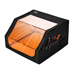
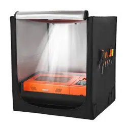
We strongly recommend placing the machine in a well-ventilated room with a sealed door and
curtains on windows to effectively avoid direct viewing of the laser beam as well as smoke,
steam, particles, and other highly toxic substances.
The high-energy diode laser beam generates extremely high temperatures and a large amount
of heat due to material combustion during engraving and cutting. Certain materials are prone
to ignition during cutting operations, producing flames, smoke, and steam.
Although Prex has built-in flame sensors, this technology should not be considered 100%
accurate and should only be used as a warning system.
During Prex operation, if flames are detected, the machine will stop the laser and sound an
alarm for abnormal conditions. Please pay attention to the machine's operating status.
During operation, ensure that any flash fire/flame is properly controlled and extinguished.
5.
6.
7.
8.
9.
7
8
10
9
16
15
14
13
12
11
17
1
2
3
4 5 6
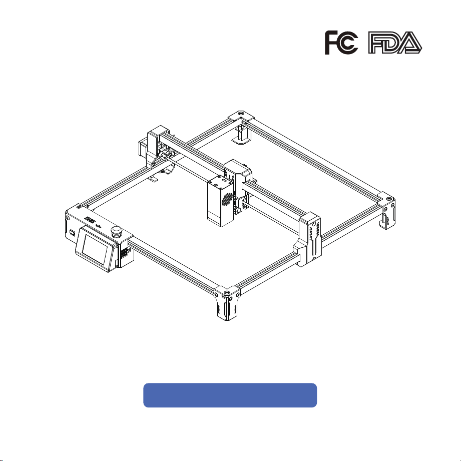
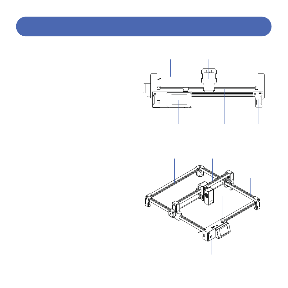
1. Y-axis motor
2. X-axis frame
3. Laser module
4. Touch screen
5. Synchronous shaft
6. Support feet
7. Left frame
8. Rear frame
9. X-axis motor
10. Laser bracket
11. Power port
12. USB port
13. TF card port
14. Emergency stop
15. Front frame
16. Right frame
17. Power switch
5
Laser Engraver Introduction
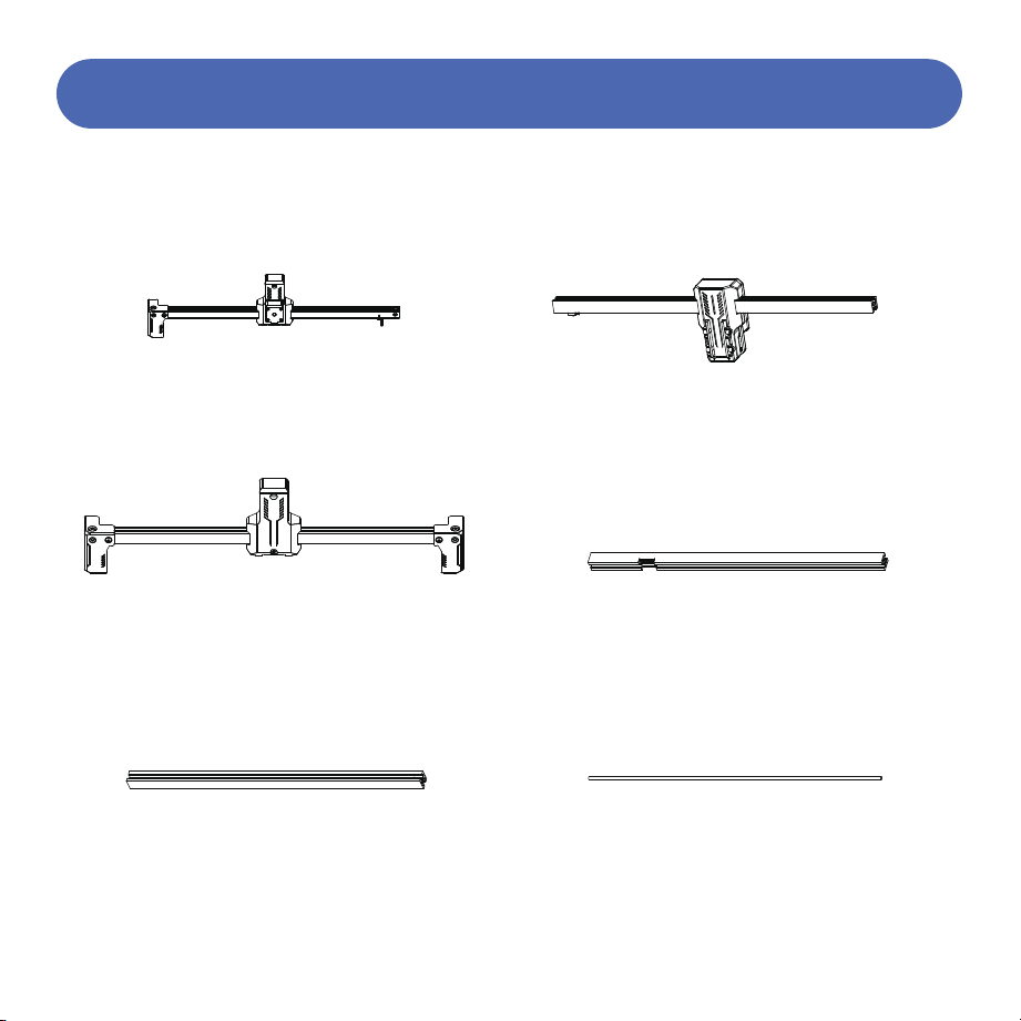
Left frame module
Laser bracket module
Right frame module
Front frame
Rear frame
Synchronous shaft
6
Packing List
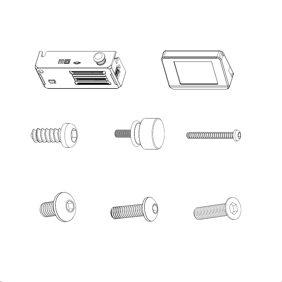
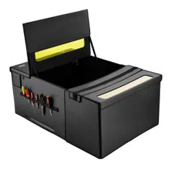
Control box with wire Touch screen with wire
M3X8 self-tapping screws X2
M3X10 thumb screws X2
M3X25 self-tapping screws X2
M5X8 screws X3 M5X16 screws X3 M5X20 countersunk screws X1
7
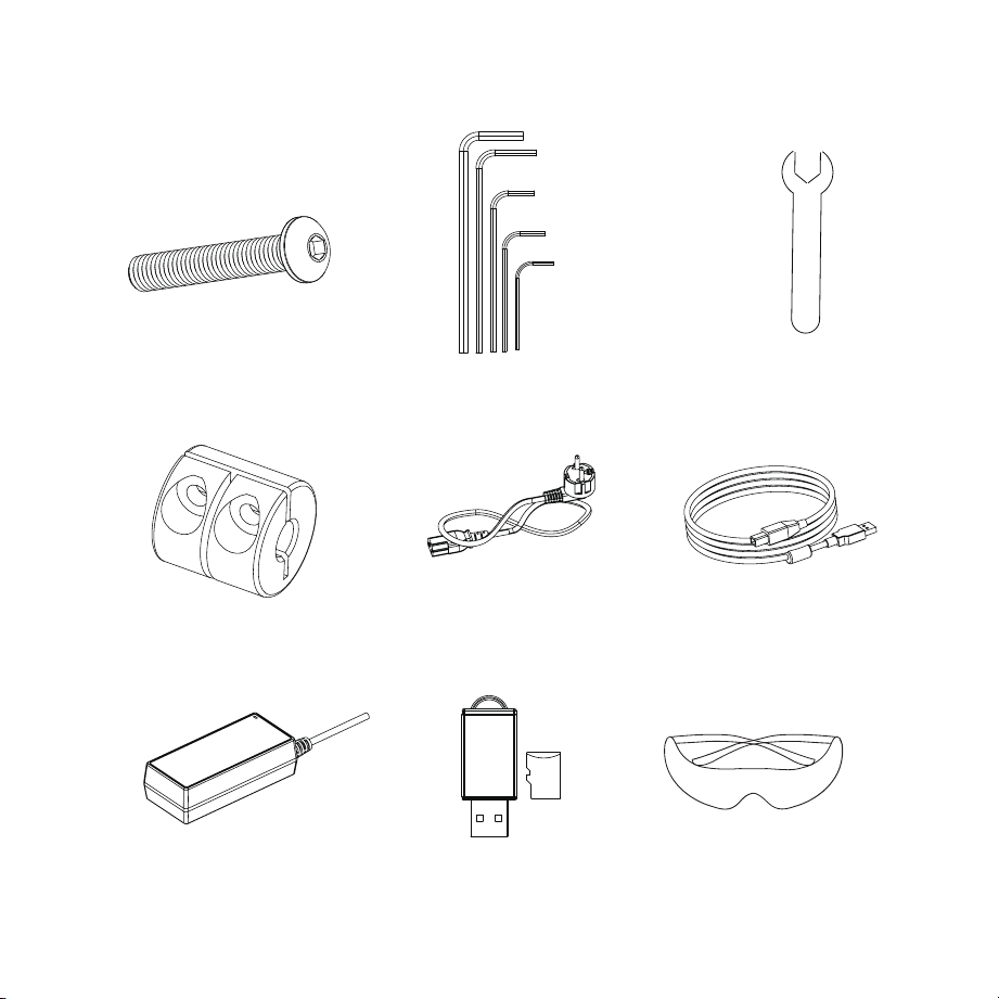
M5X30 screws X3 Wrench kit Open-end wrench
Couplings X2 Power cord Data cable
Power adapter TF card Safety goggles
8
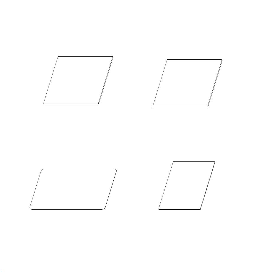
Acrylic sheets X2 Plywood X2
Aluminum sheets X4 Kraft cardstock X4
9
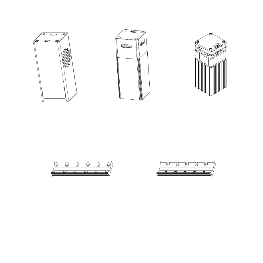
20W Laser Head 10W Laser Head 5W Laser Head
(Provided according to model)
5W/10W Laser Head
Mounting Block and Screws
20W Laser Head
Mounting Block and Screws
(Provided according to model)
10
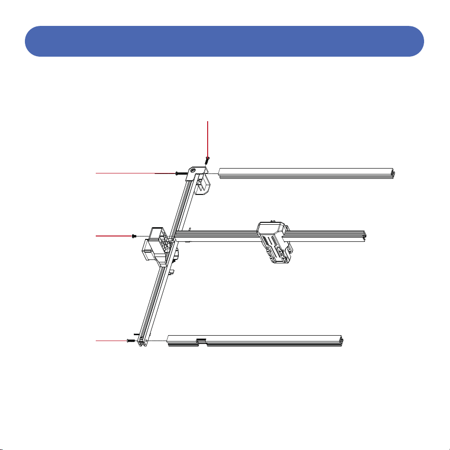
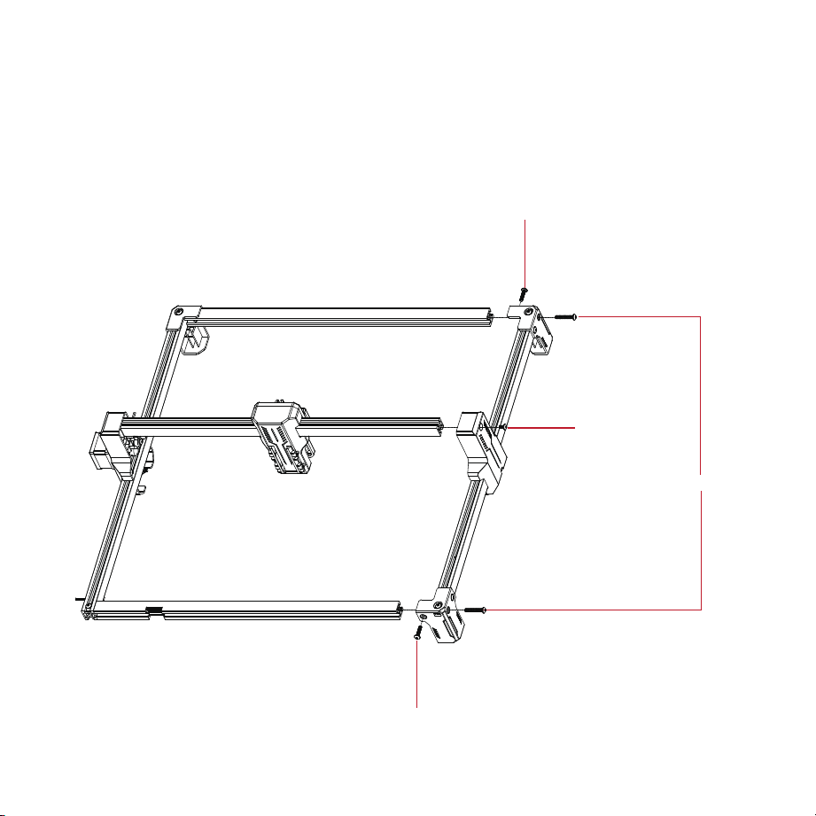
1. Assemble the left frame module with the front frame, rear frame, and laser bracket.
M5X16 screws
M5X30 screws
M5X8 screws
M5X20
countersunk
screws
11
Assembly Steps
2. Assemble the right frame module with the front frame, rear frame, and laser bracket.
M5X16 screws
M5X16 screws
M5X8 screws
M5X30 screws
12
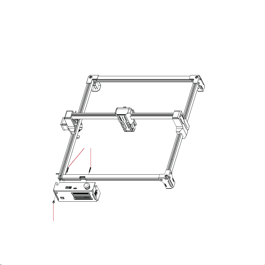
3. Assemble the control box with the front frame.
M3X25 self-tapping screws
M5X8 screws
13
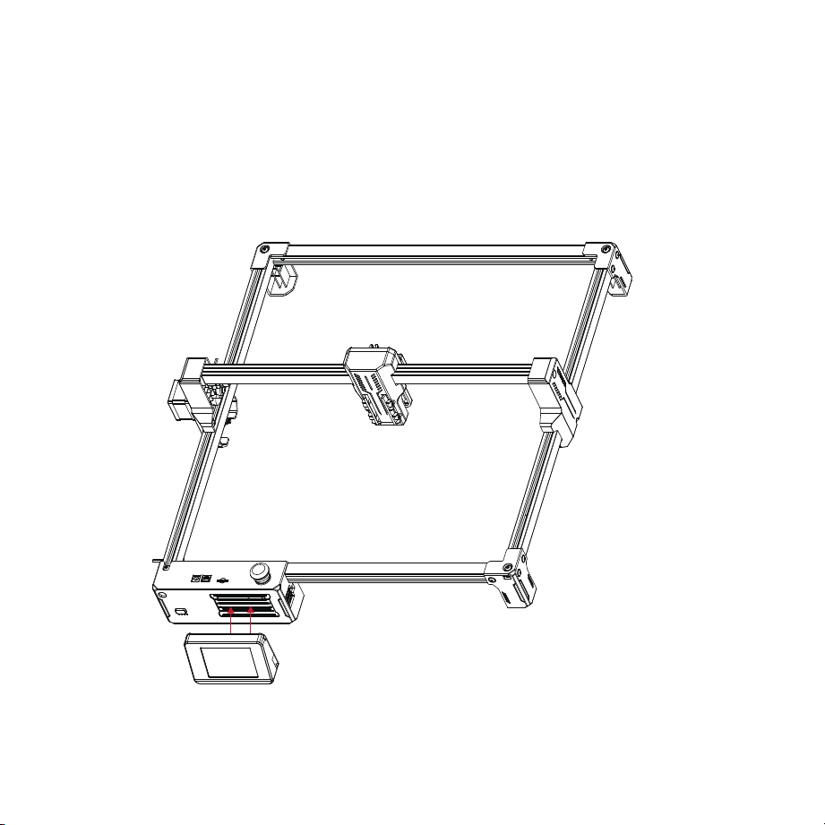
4. Hang the hook on the back of the screen on the control box louver.
14
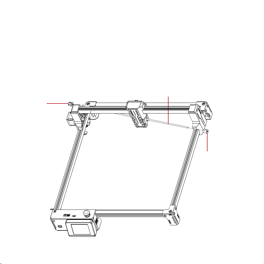
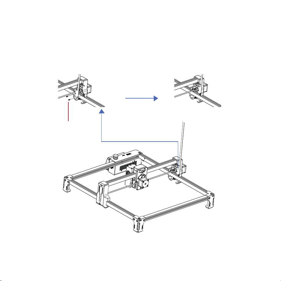
5. Synchronous shaft assembly.
15
Coupling
Coupling
First, push the laser
bracket all the way to the
back, ensuring both sides
are flush with the plastic
components.
1. Insert the synchro-
nous shaft into the
opening of the
laser bracket,
placing a coupling
on each side.
2.
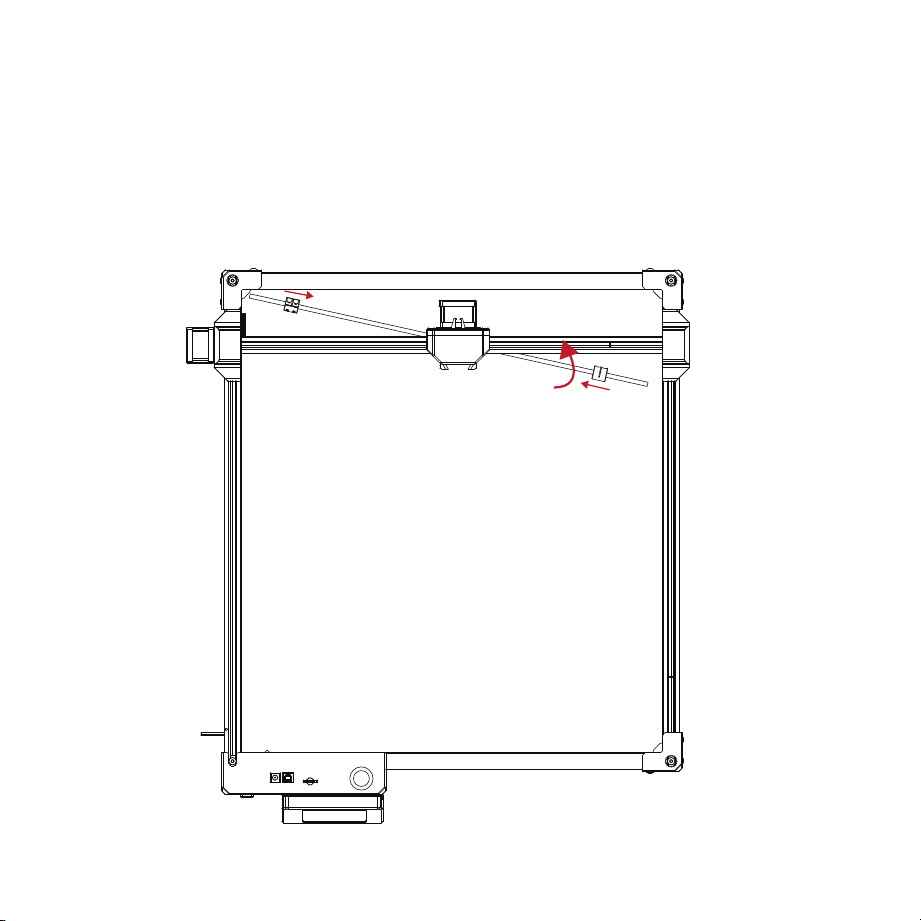
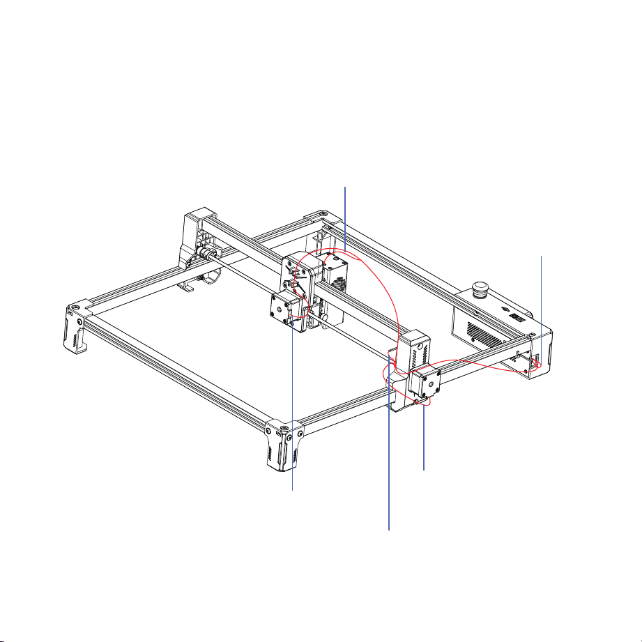
16
Push both couplings inward and rotate the synchronous
shaft so that it is parallel to the laser bracket.
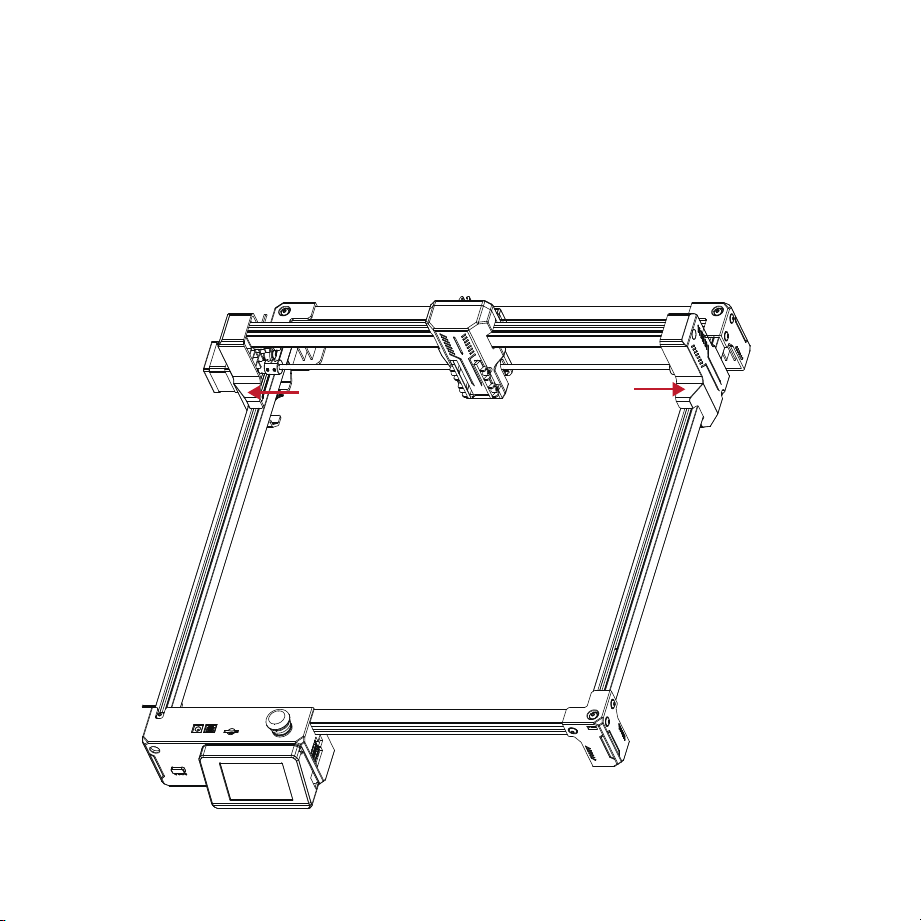
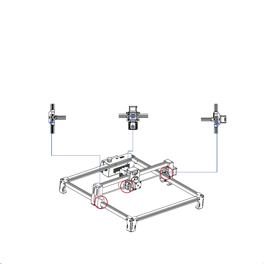
17
Push both couplings outward so that the couplings fit over the
shafts on both sides, then tighten the couplings with a wrench.
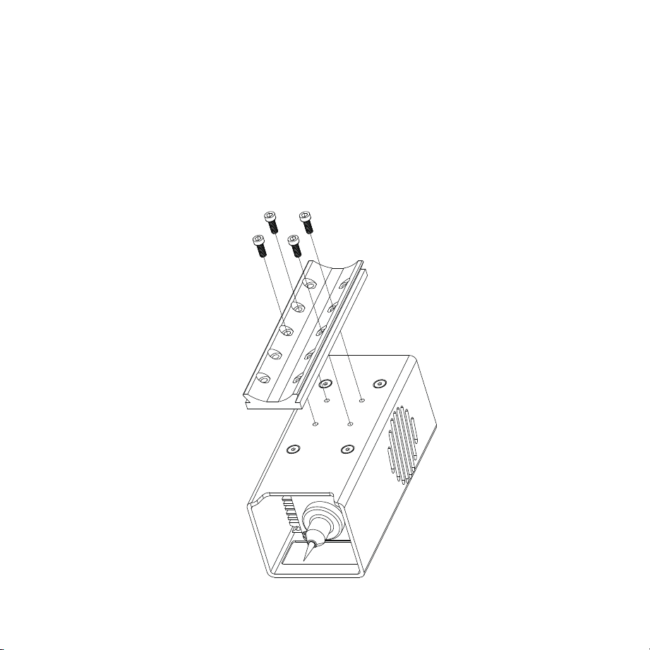
18
Secure the laser head backplate
with the provided M3 screws.
6. Laser head assembly.
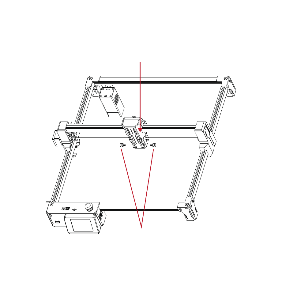
19
Insert the laser head
backplate into the
corresponding slot.
Tighten the M3 thumb screws on both sides, adjust the
laser head to the desired height, and tighten the thumb
screws.
20
M3*8 self-tapping screws X2
7. Wire harness Mylar sheet assembly
21
1-axis wiring harness
Y-axis wiring harness
X-axis wiring harness 4P
X-axis wiring harness
Y-axis wiring harness 4P
8. Wiring
22
1. Adjusting Eccentric Nuts
Check whether the POM wheels of the left and right frames and laser bracket match the
aluminum profiles, and whether the movement is smooth without jamming.
Notes:
1. Optimal condition: When rotating the POM wheel, you should feel slight friction
between the POM wheel and the aluminum profile.
2. If the wheel rotates in the air without contacting the aluminum profile, use an
open-end wrench to adjust the eccentric nut.
Machine Calibration
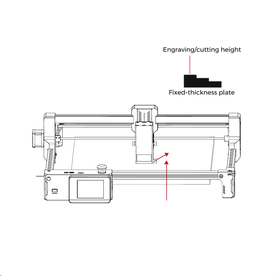
23
Laser Module
Fixed-thickness plate
Engraving material
2. Laser Module Focusing
1. Software Download
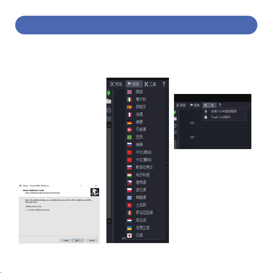
2. Software Installation
3. Language
4. CH340 Driver Installation
5. Power-On Self-Test
LaserGRBL is one of the most popular DIY
laser engraving software currently available,
downloadable from the LaserGRBL website
http://lasergrbl.com/download (installation
packages are also available on the
manufacturer-provided TF card or USB
drive).
Introduction: LaserGRBL is easy to use.
However, LaserGRBL only supports Windows
systems (WinXP/Win7/Win8/Win10). For Mac
users, you can also choose LightBurn, which
is also an impressive engraving software, but
it is not free. This software also supports
Windows systems.
Double-click the software installation
package to begin software installation, then
click "Next" until installation is complete.
Click "Language" at the top
menu and select your
preferred language.
Connect the power cord to the DC
port of the motherboard.
Press the power button to turn on the
machine. Press the power button
briefly 3 times, and the machine will
run a test program (after returning to
the origin, it will traverse the
maximum engraving area twice).
24
Machine Testing
Click "Tools" in the menu to
install the CH340 driver (this
feature is not available in some
software versions).
Copy the "CH340SER" file from
the TF card to your computer
and install it.
Method 1:
Method 2:
5.1
5.2
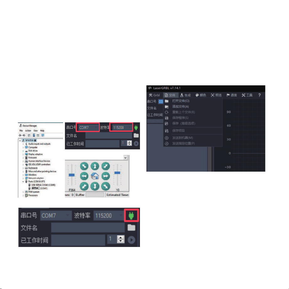
6. Connecting to Computer 7. Loading Engraving Files
Click "File" and then "Open File" sequentially, as shown in
the figure, then select the graphic to be engraved.
LaserGRBL supports files in NC, BMP, JPG, PNG, and other
formats.
25
Figure A
Figure D
Figure C
Figure B
1. Connect the machine to the computer with a data cable.
2. Open LaserGRBL on the computer.
3. Select the specific port number and baud rate - 115200
(Figure A).
Click the green plug icon (Figure B). When the direction
indicator lights up, it indicates a successful connection
(Figure C). Generally, there is no need to manually select
the COM port unless multiple serial devices are connected
to the computer. You can find the computer's port in the
Windows Device Manager (as shown in Figure D). A
simpler method is to try the displayed port numbers one
by one.
4.
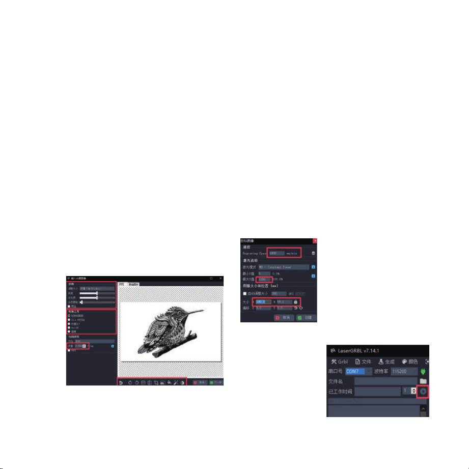
8. Setting Image Parameters, Engraving
Mode, and Engraving Quality
9. Setting Engraving Speed, Engraving
Power, and Engraving Size
10. Starting
Engraving
Color
adjust-
ment;
Intensity
adjustment
Select
engraving
mode
Direction adjustment; Pattern cutting
Default engraving speed is
1000, adjustable as needed
Set power value - excessive
power affects engraving
quality
Enter the dimensions of the
graphic to be engraved
After returning to the
main interface, click
the Start button as
shown to begin
engraving.
26
Quality:
12-15
(Recom-
mended)
LaserGRBL can adjust sharpness, brightness, contrast,
highlights, and other properties of the target image. We can
preview the window effect during adjustment and fine-tune
to achieve satisfactory results.
In engraving mode, you can typically choose between "Line
To Line Tracing" and "1bit Bw Dithering". "1bit Bw Dithering"
is more suitable for engraving grayscale images. For cutting,
please select "Vectorize" or "Centerline".
Engraving line width primarily refers to the laser scanning
line width. This parameter mainly depends on the size of the
engraving machine's laser spot. Note: The recommended
engraving quality range is 12-15. Different materials react
differently to laser irradiation, so specific values depend on
the specific engraving material.
At the bottom of the preview window, you can also rotate,
mirror, cut, and perform other operations on the graphics.
After completing the above settings, click next to enter the
settings for engraving speed, engraving power, and
engraving size.
1.
2.
3.
4.
The recommended engraving speed is 8000, which is
considered relatively appropriate after repeated
experiments. Of course, you can increase or decrease this
speed according to your preferences. Faster engraving
speeds save time but lead to reduced engraving quality.
In laser mode, there are two commands: M3 and M4. If your
laser only has the M3 command, please check whether this
laser mode is used for GRBL configuration. For GRBL
configuration, please refer to the official LaserGRBL
instructions.
Engraving power selection. Choose according to different
materials.
Finally, set the dimensions and click the "Create" button to
complete all engraving parameter settings.
1.
2.
3.
4.