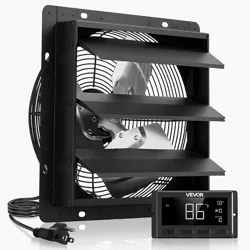

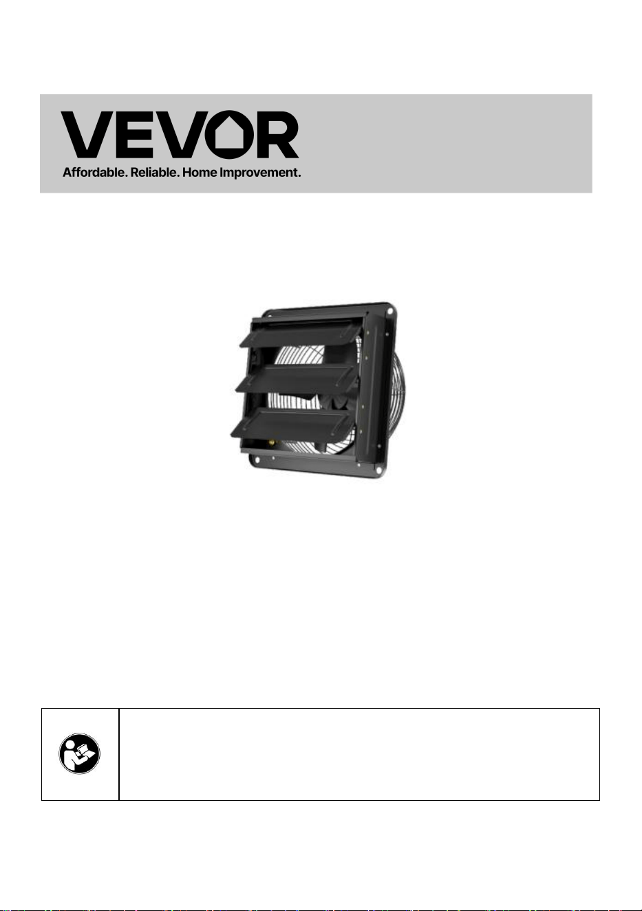
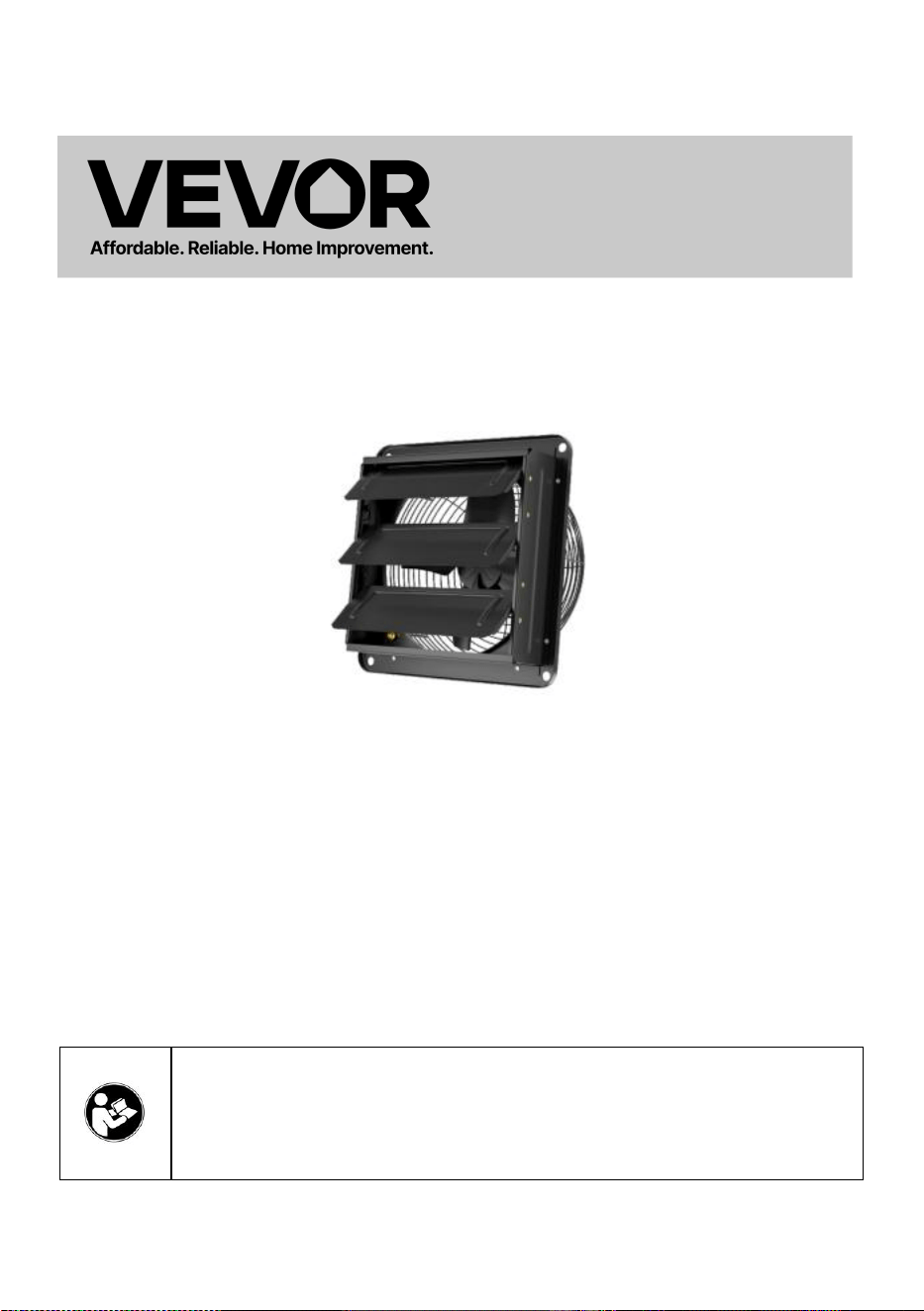
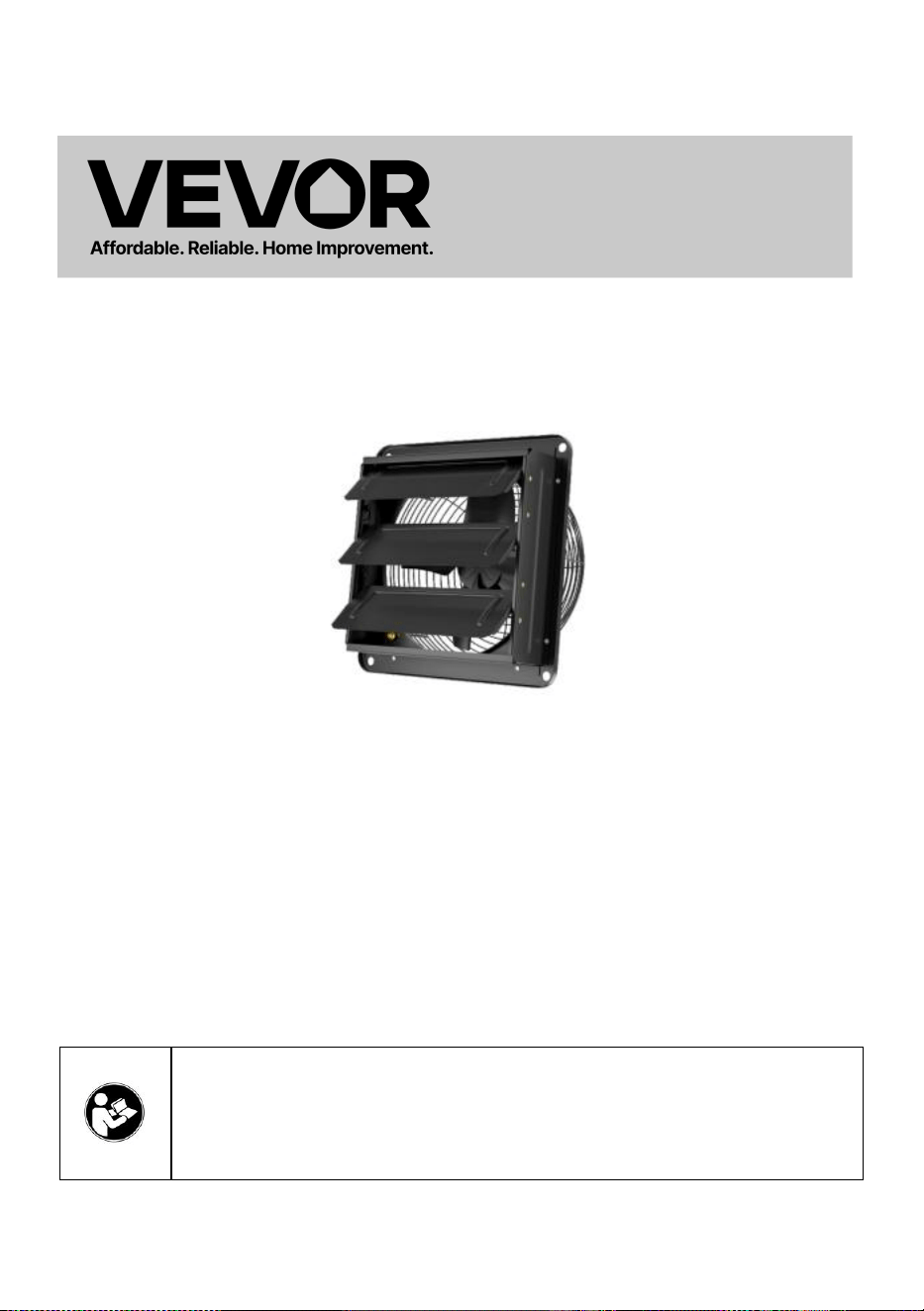
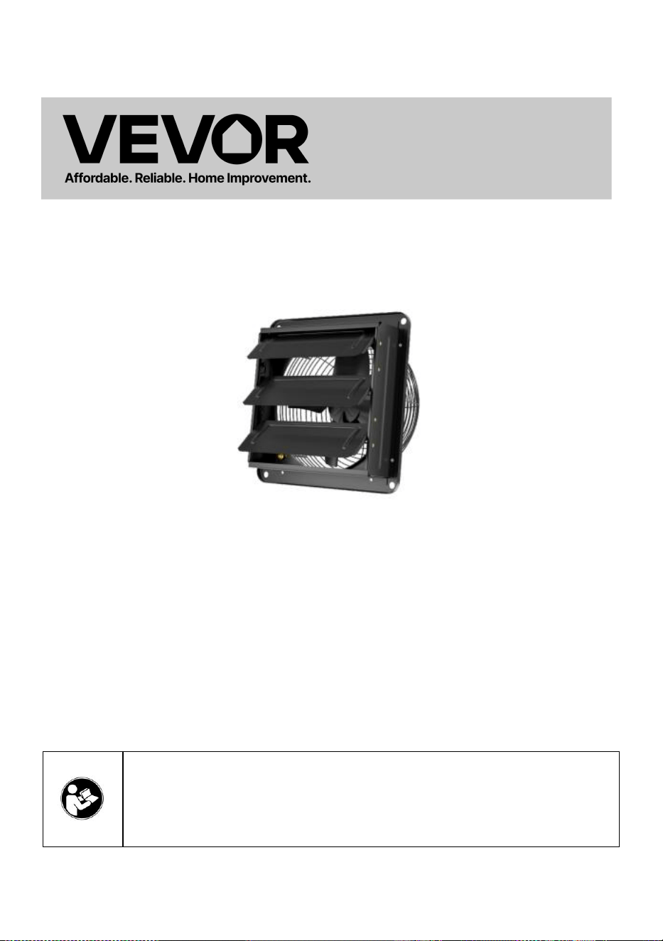
SHUTTER EXHAUST FAN
MODEL:HA-300ME/HA-250ME/HA-350ME/HA-400ME

1
MODEL:HA-300ME/HA-250ME/HA-350ME/HA-400ME
This is the original instruction, please read all manual instructions
carefully before operating. VEVOR reserves a clear interpretation of our
user manual. The appearance of the product shall be subject to the
product you received. Please forgive us that we won't inform you again if
there are any technology or software updates on our product.
Warning-To reduce the risk of injury, user must read
instructions manual carefully.
SHUTTER EXHAUST FAN
2
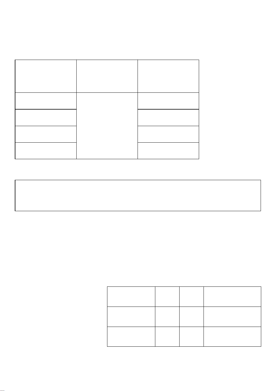
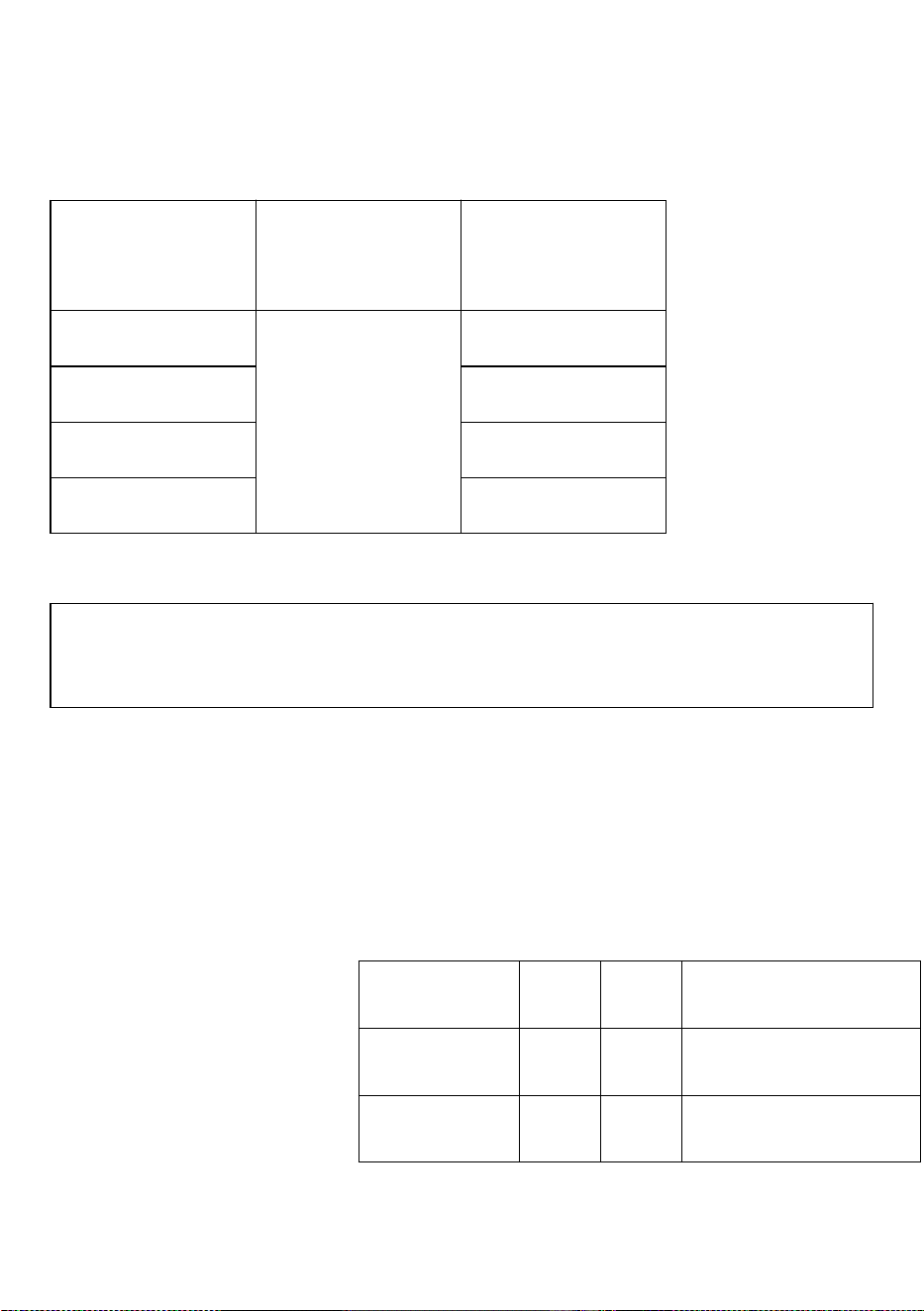
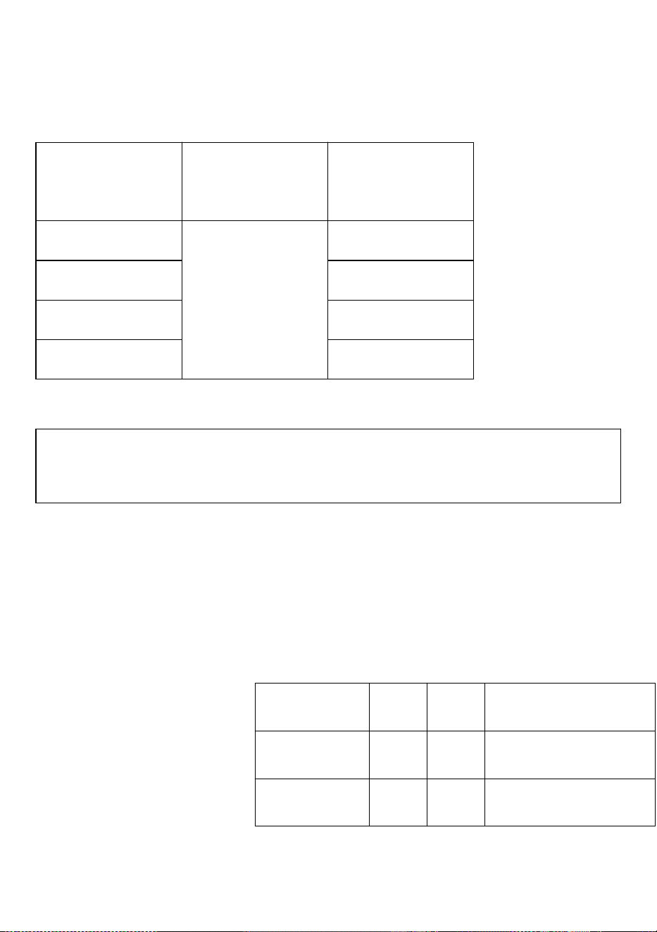
Specifications
Model
Voltage Frequency
Power (W)
HA-300ME
100-240V~
50/60Hz
50
HA-250ME
30
HA-350ME
80
HA-400ME
98
Accessories List
Temperature and Humidity Sensor Cable (2.5m) *1,Controller *1Audio Cable (3m) *1
Screws *4,Rubber Grommets *4
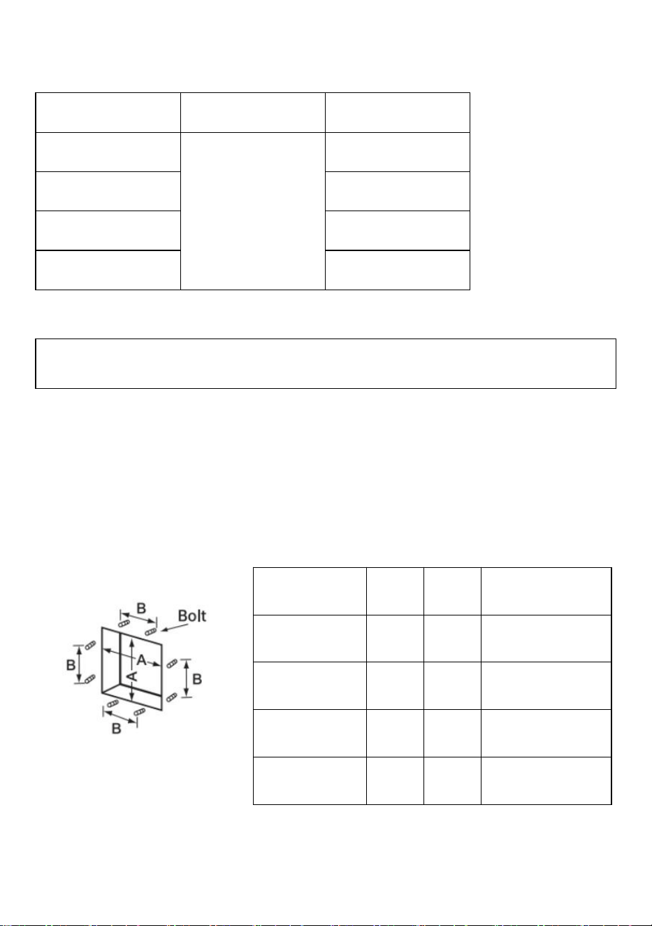
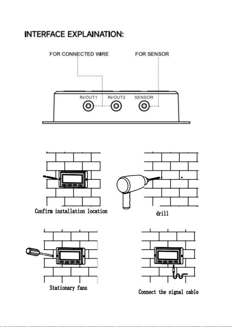
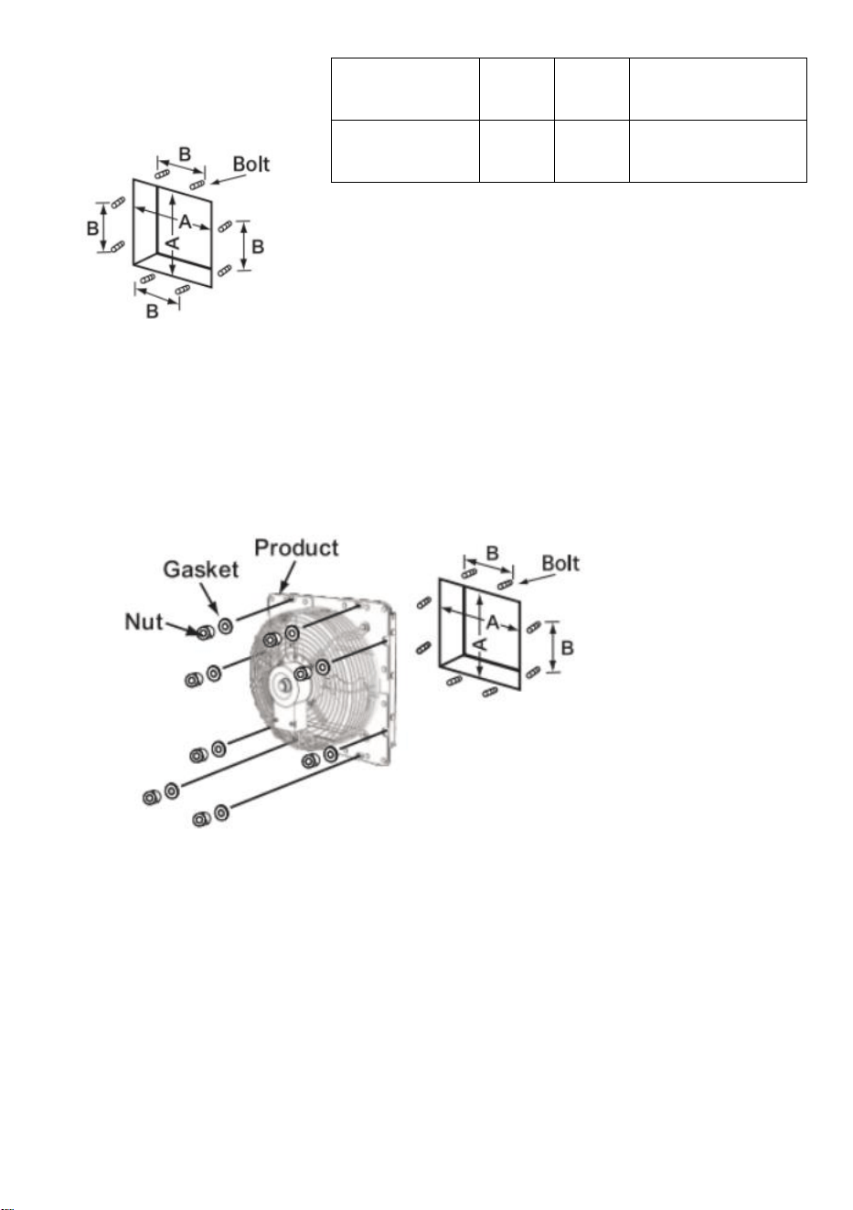
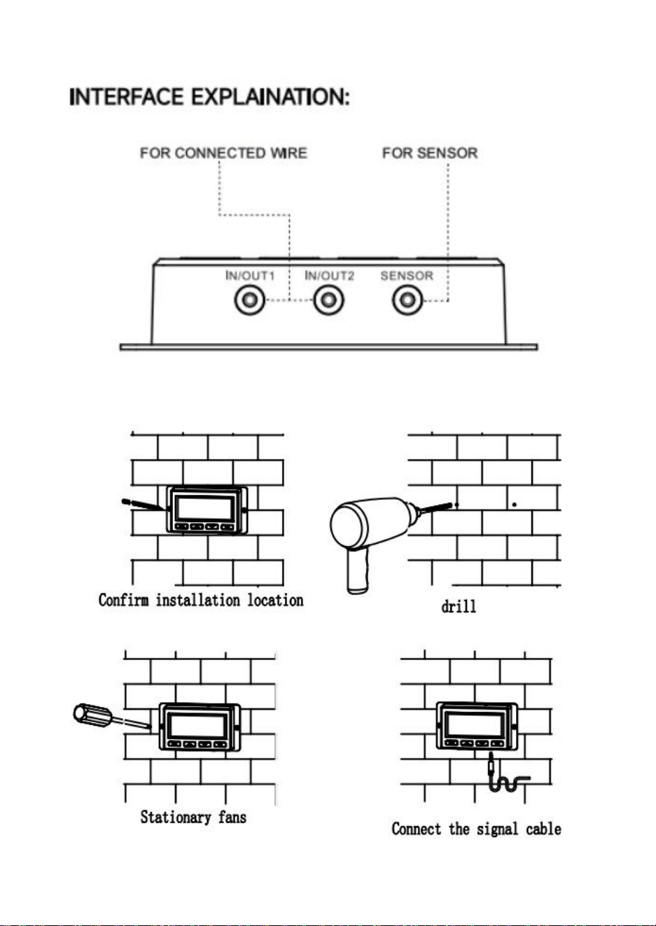
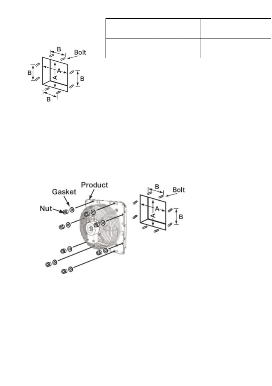
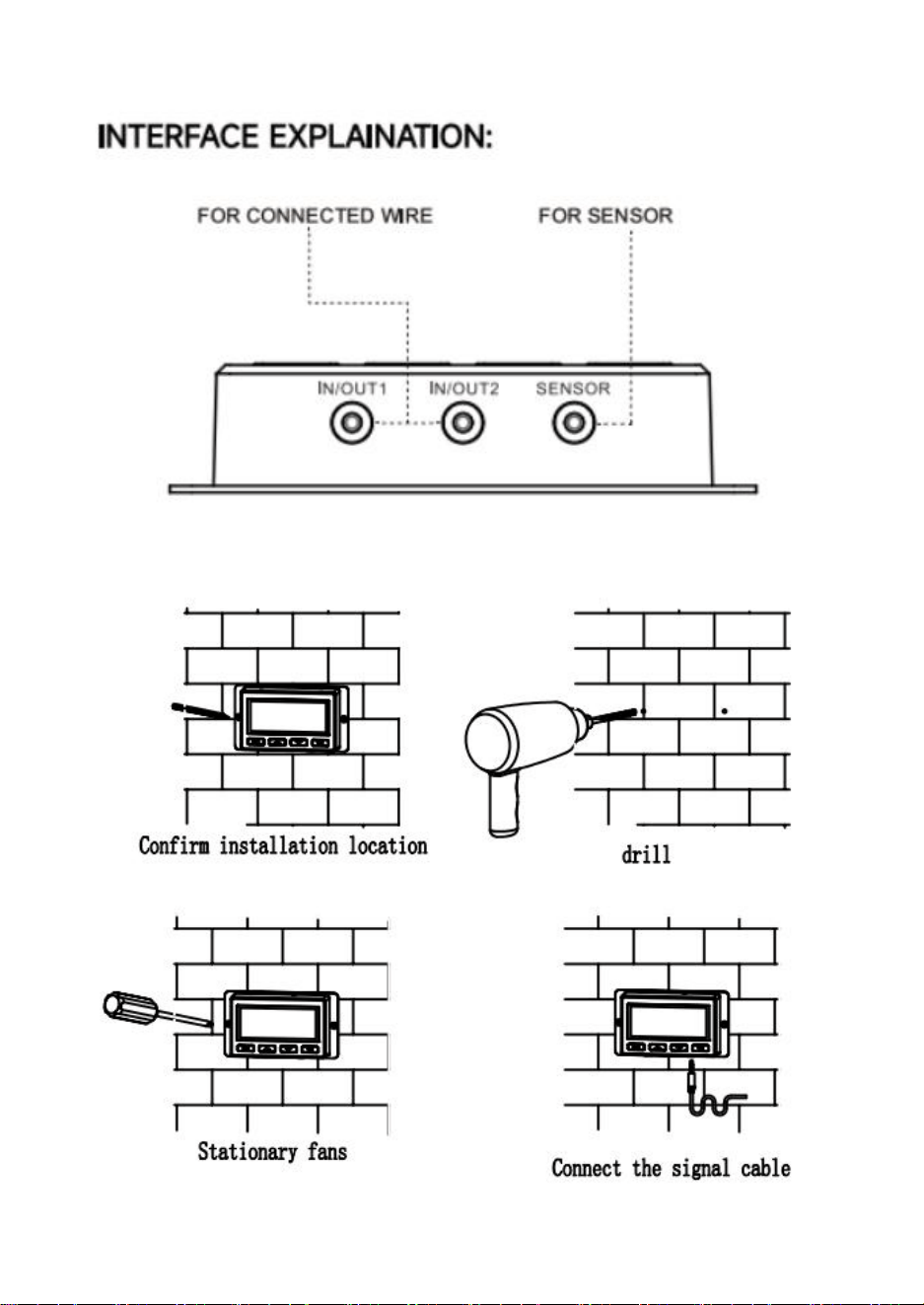
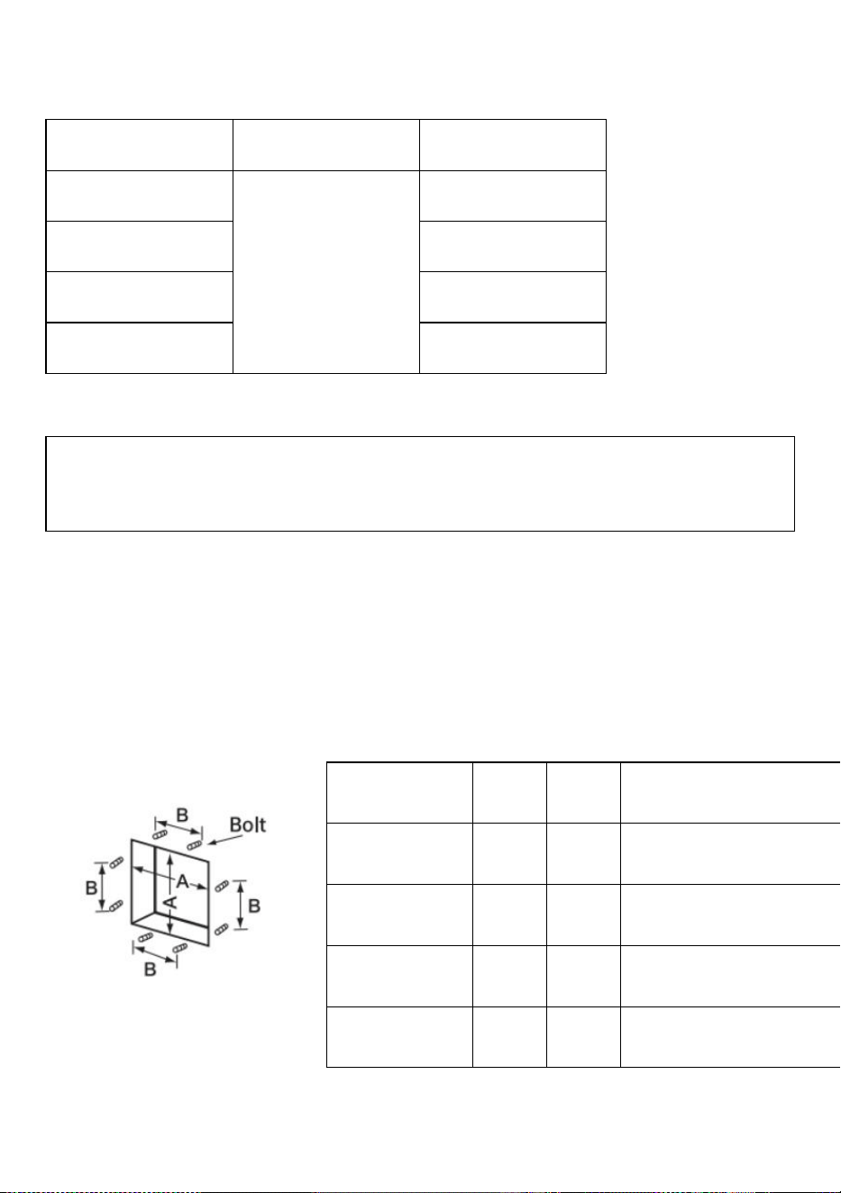
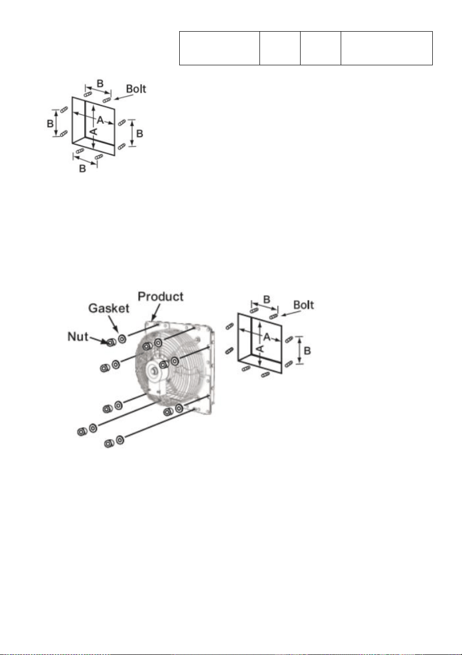
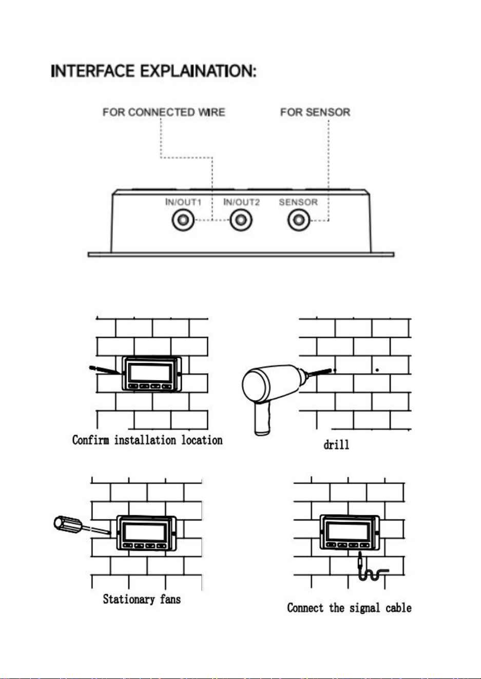
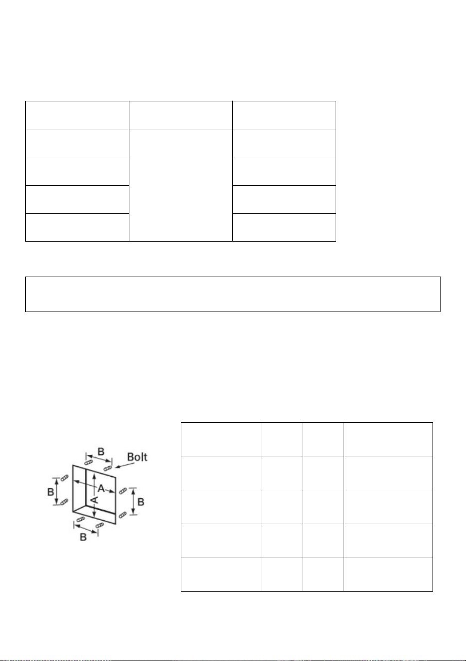
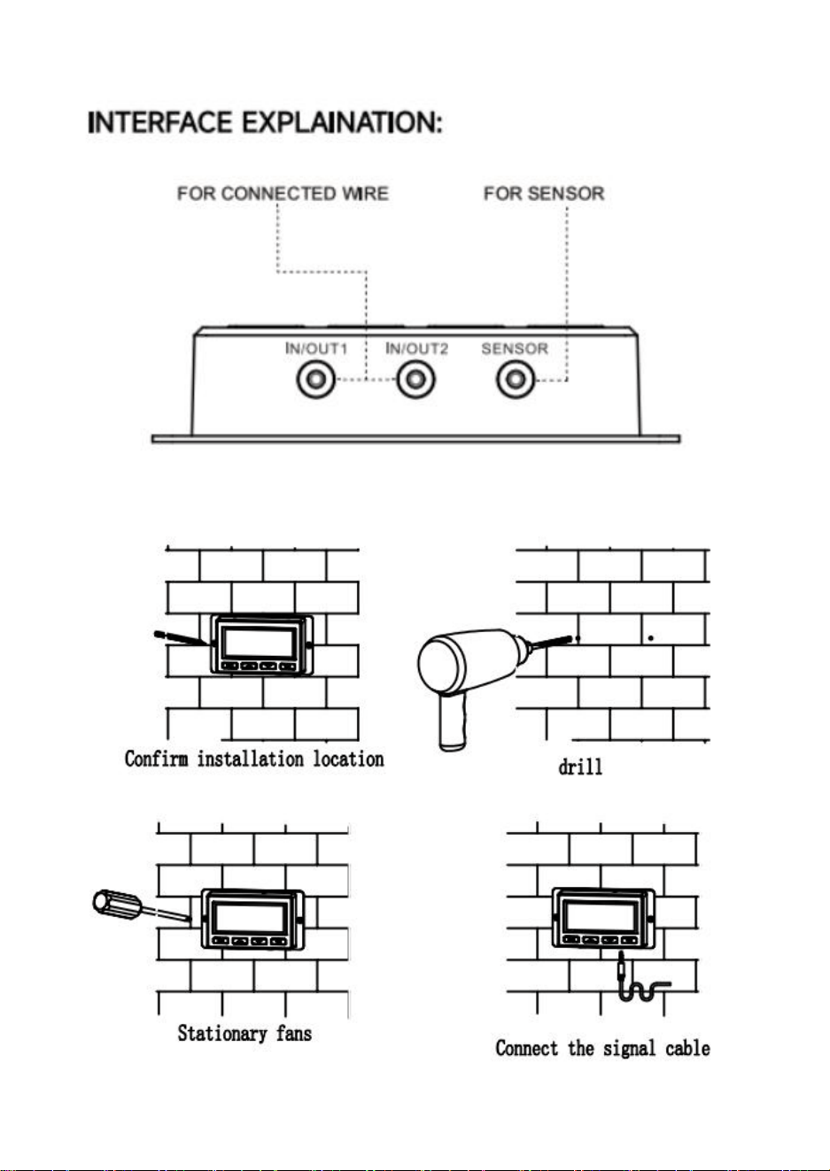
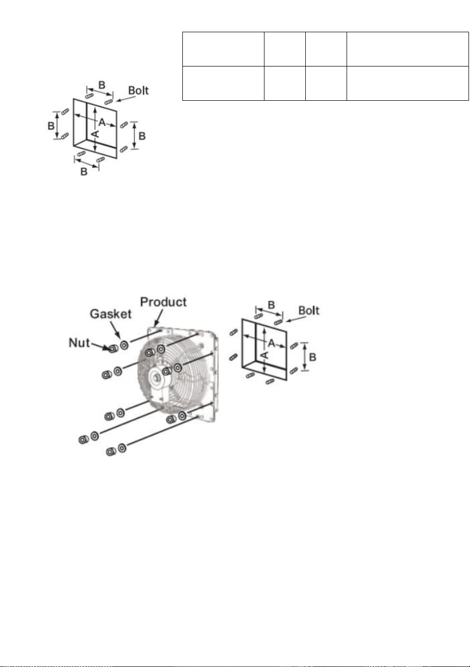
EASY TO MOUNT:
Drill holes on the wall and insert the bolts into the following
positions.
Unit: mm
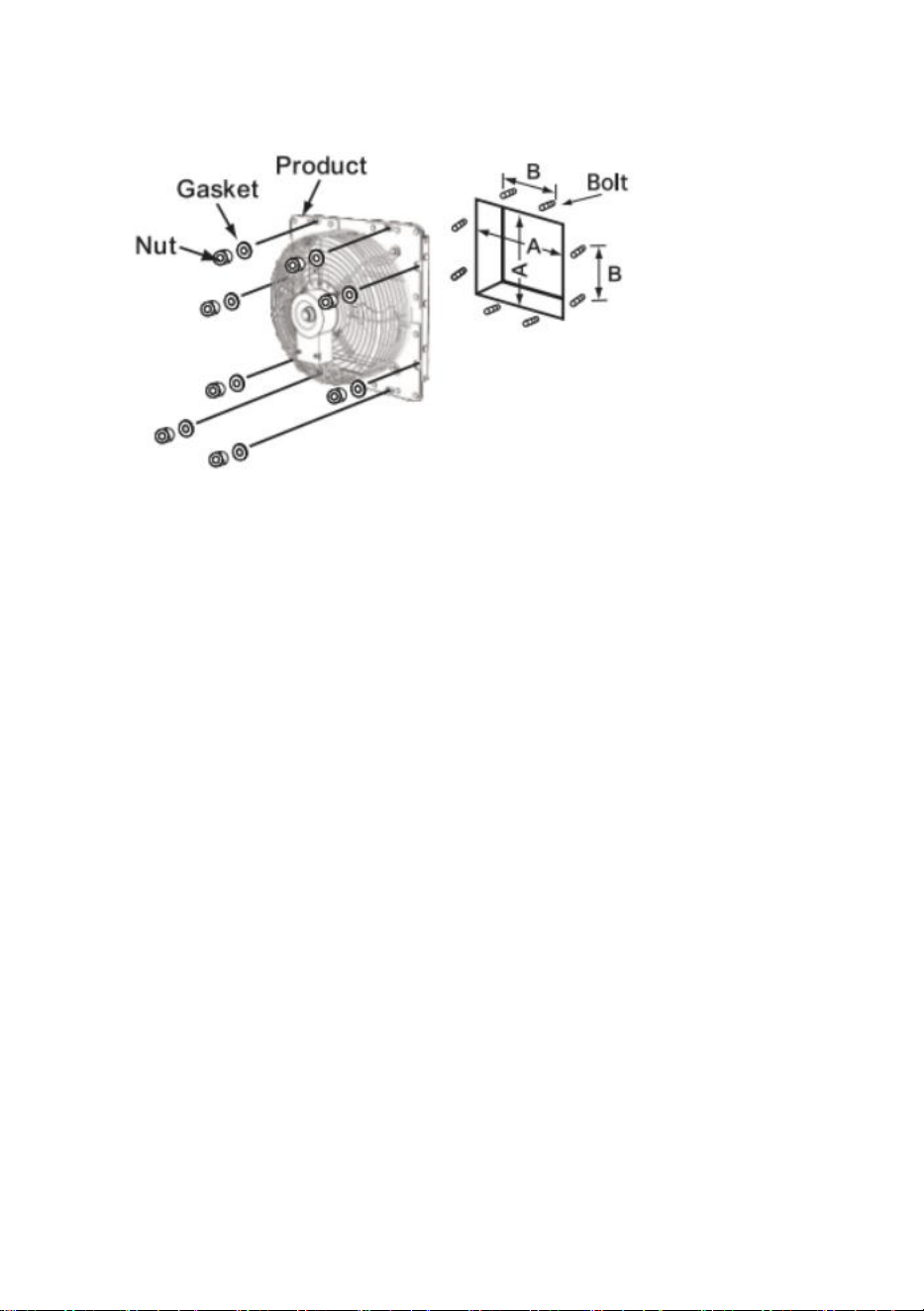
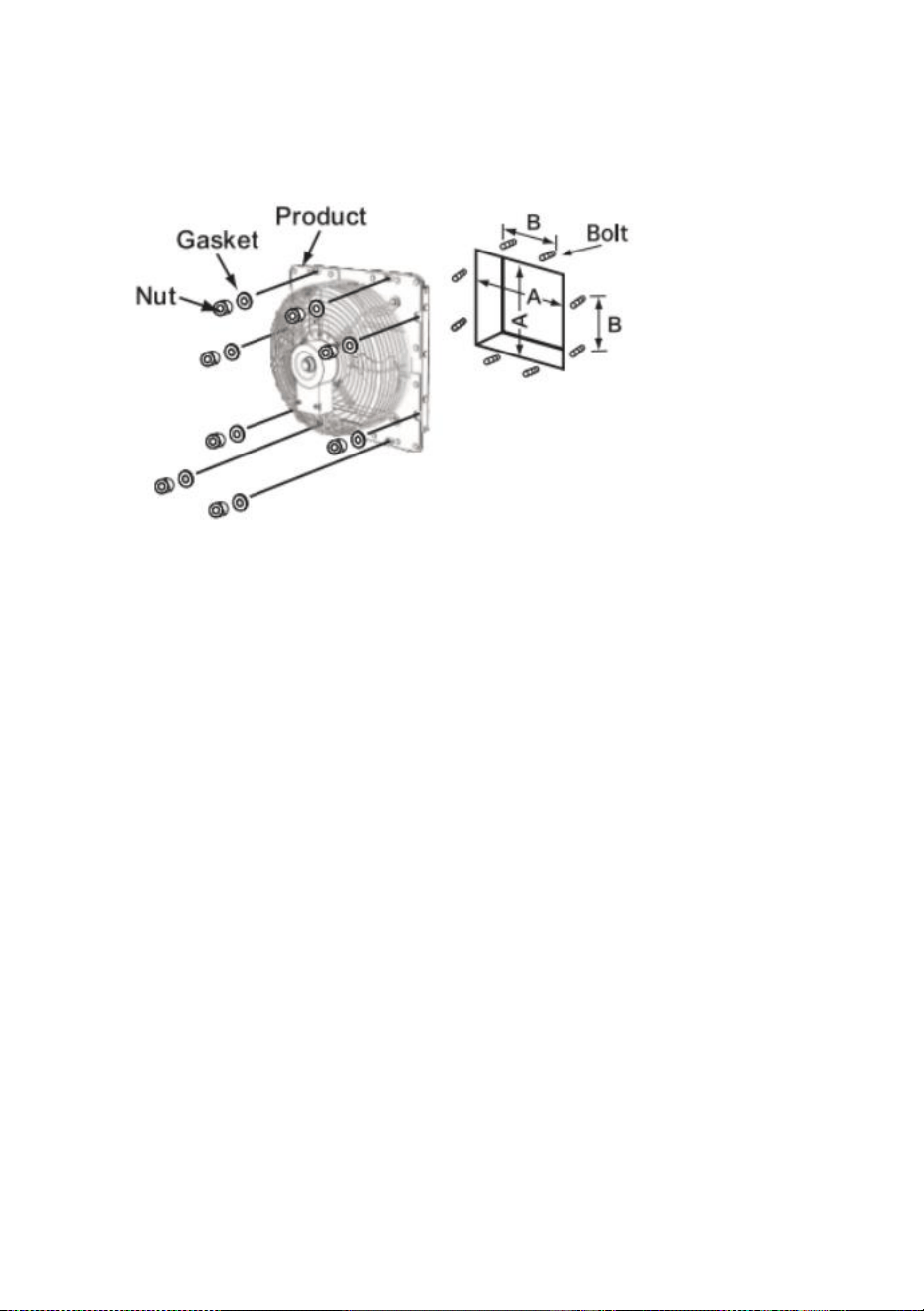
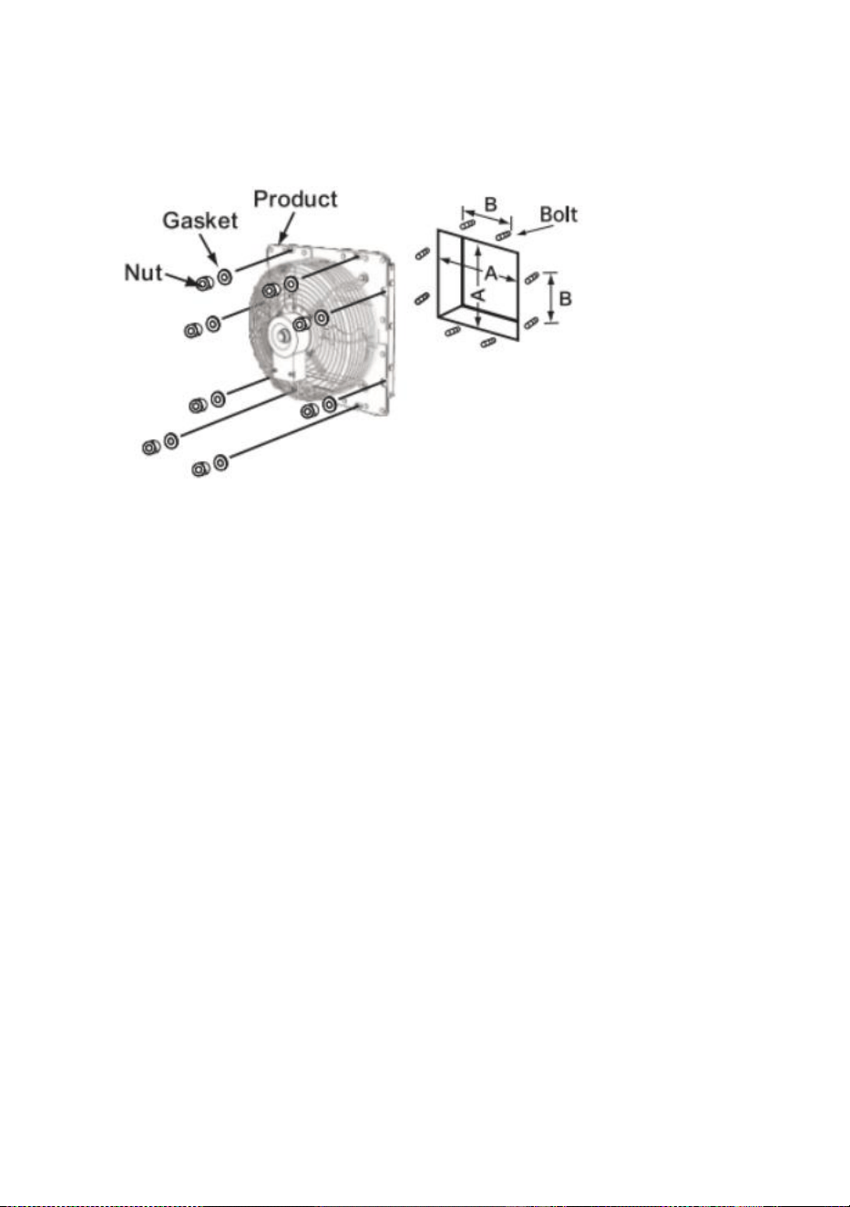
Install the fan body.
Pass the bolts through
the eight mounting holes on the outer frame and secure them with
Size
A
B
Bolt Diameter
HA-250ME
269
174
15x9
HA-300ME
312
190
15x9
HA-350ME
354
235
15x9
HA-400ME
412
220
15x9
3
washers and nuts.
Notice:
Be careful not to deform the blades during transportation and
installation.
If the blade is deformed, the balance of the blade is disrupted,
causing noise and vibration.
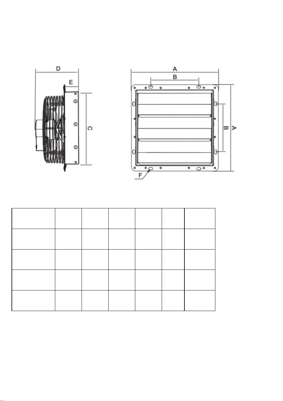
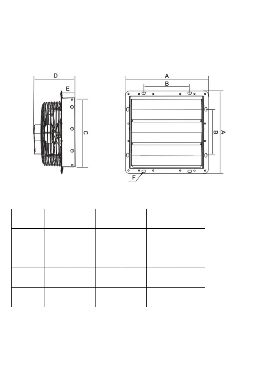
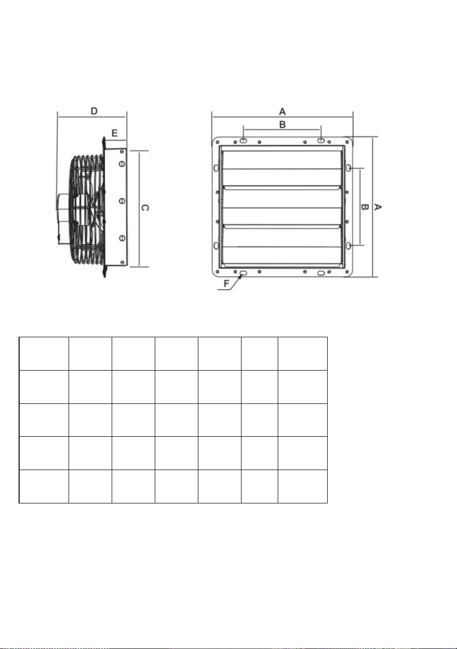
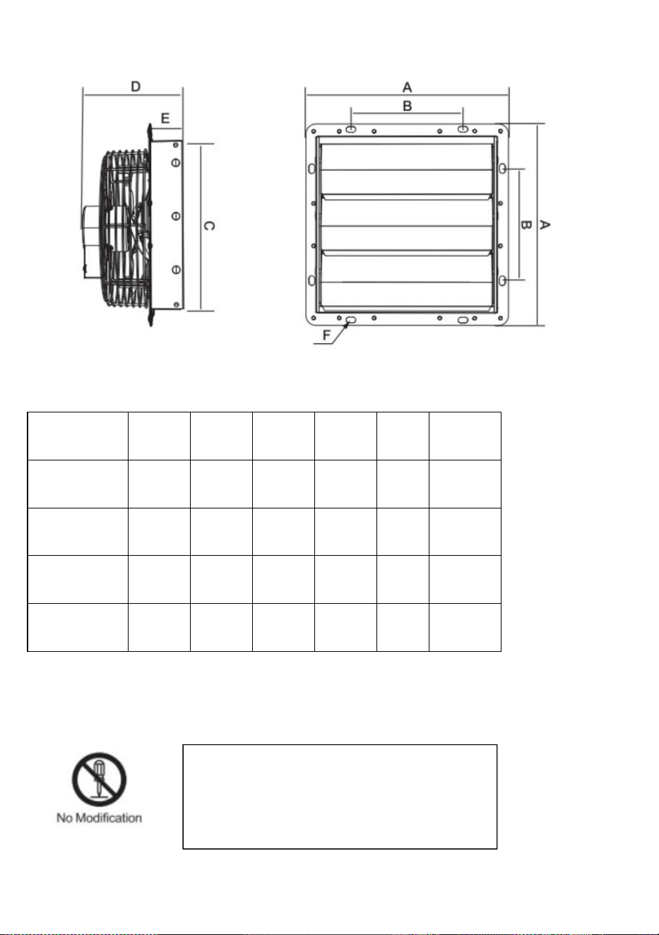
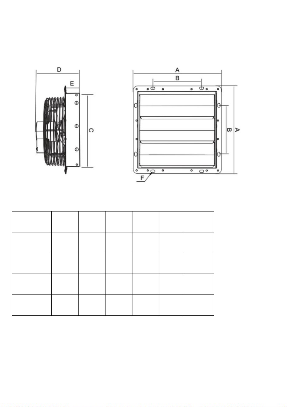
PRODUCT SIZE

4
Unit: mm
Size
A
B
C
D
E
F
250
314
174
269
170
49
15x9
300
370
190
312
193
56
15x9
350
420
235
354
185
48
15x9
400
480
454
220
221
62
15x9
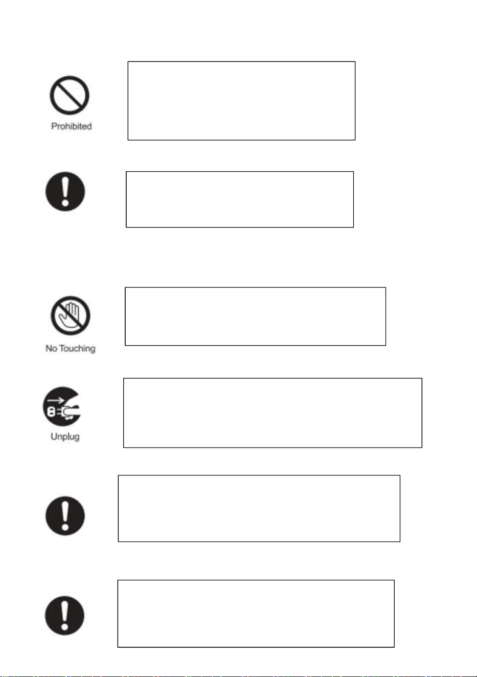
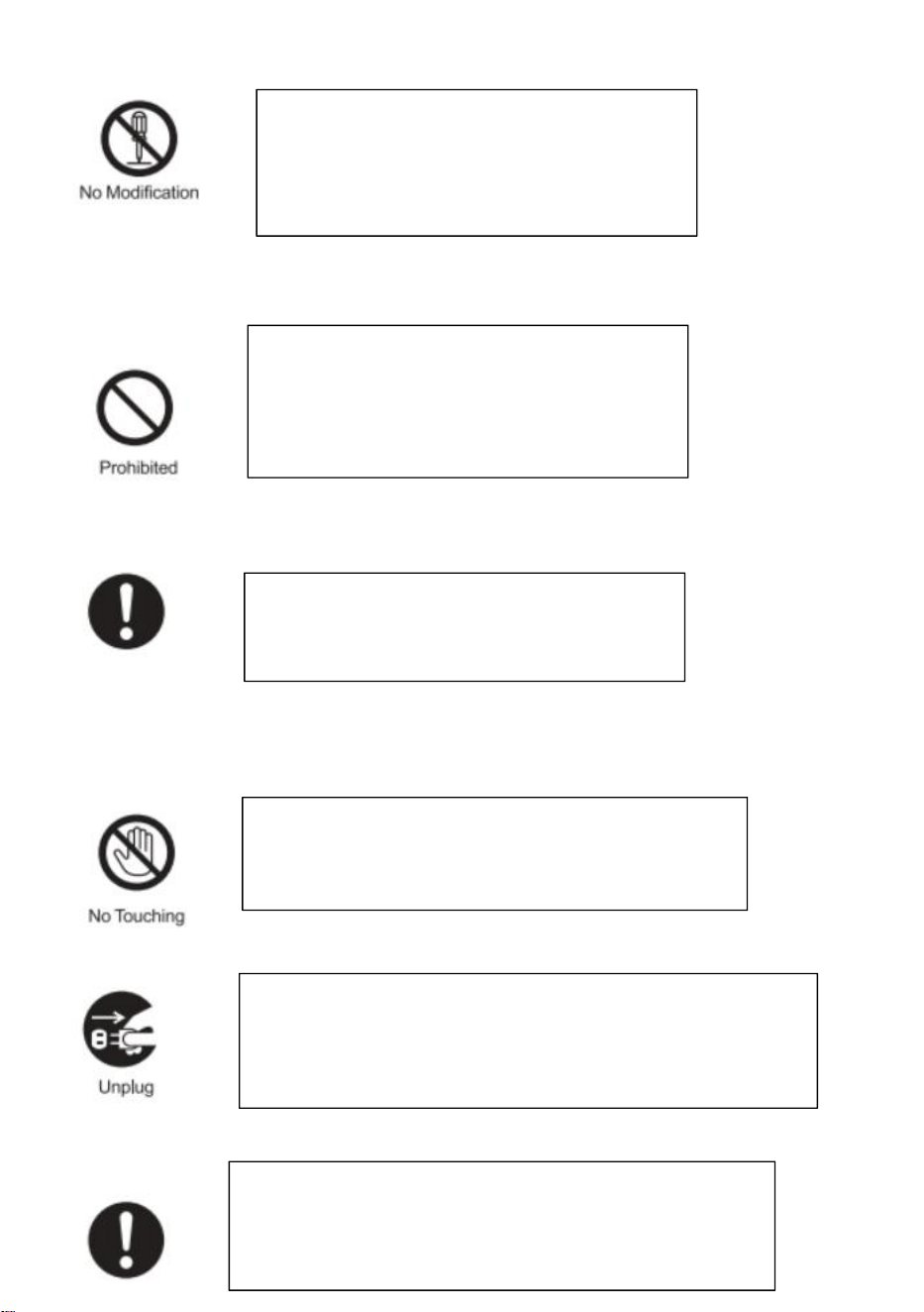
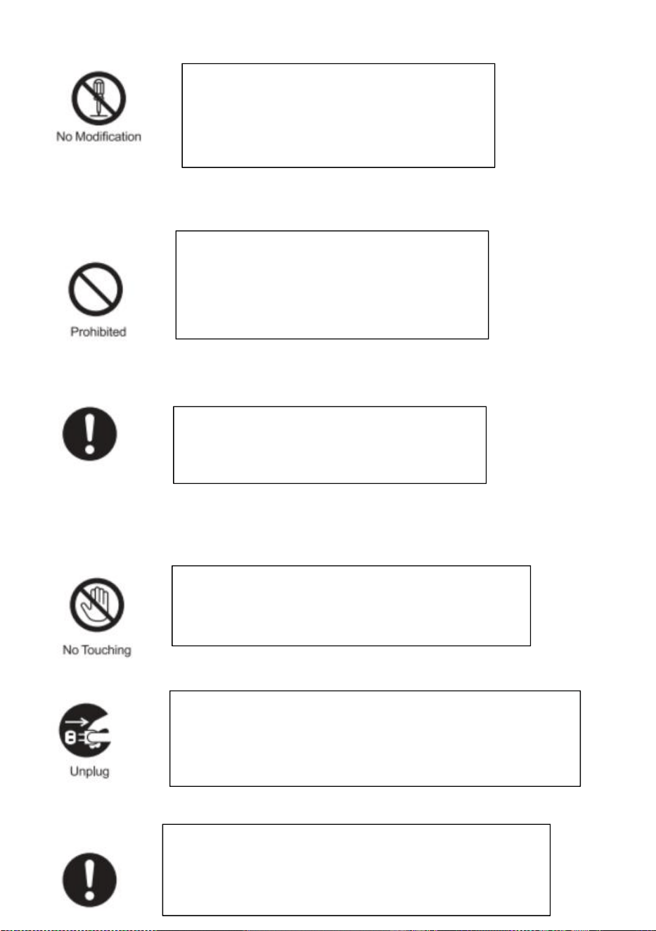
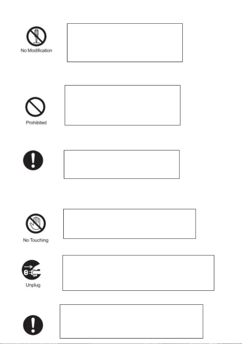
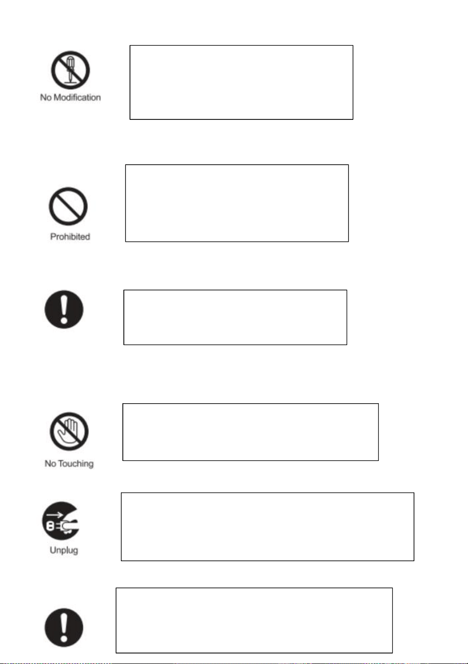
WARNING
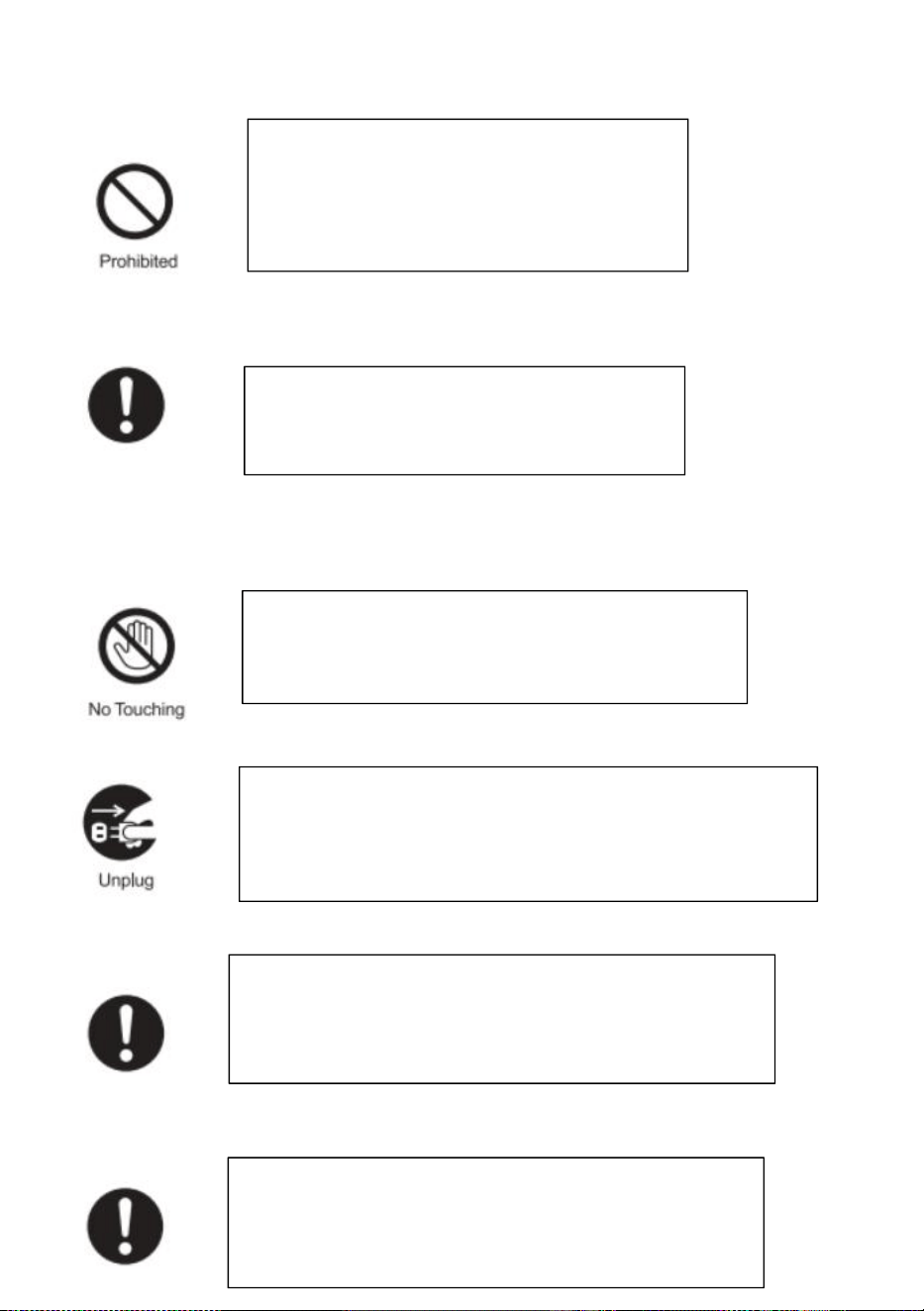
Do not disassemble, repair or modify the fan
motor. Otherwise, there is a risk of fire,
electric shock or injury.
5
NOTICE
Unplug the power plug from the wall outlet
before maintenance, or turn off the circuit
breaker at the switchboard. Otherwise, there
is a risk of electric shock or injury.
Always use at rated voltage. Otherwise,
there is a risk of fire or electric shock.
During operation, do not put fingers or objects
inside the blade. Otherwise, there is a risk of injury.
If the product is not in use for a long time please unplug
the power plug from the socket. Otherwise, there is a risk of
electric shock or fire due to deterioration of insulation.
Wear thick gloves during installation. Cut edges such as
sheet metal, plastic parts, protrusions, or corners of
equipment may cause injury.
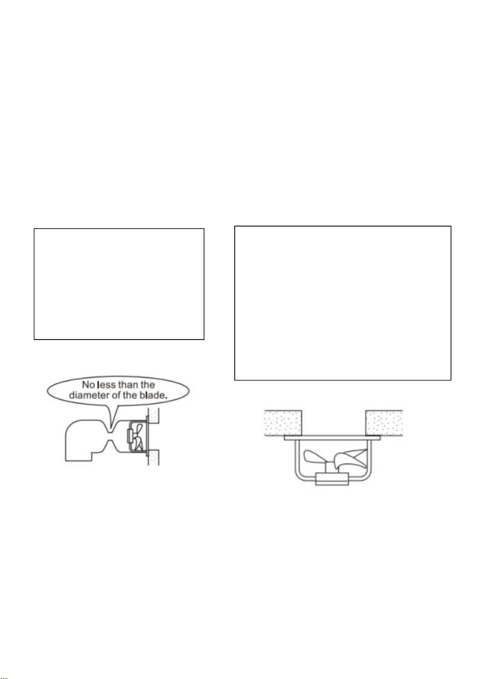
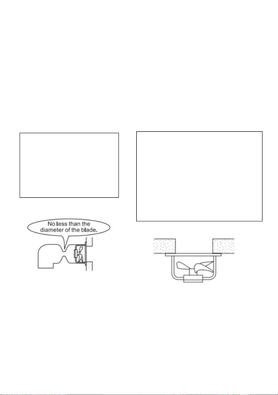
Install the fan firmly in a place where is strong enough,
If not it needs to be reinforced. Otherwise, there is a
risk of falling injury.
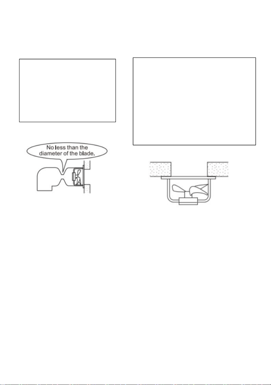
6
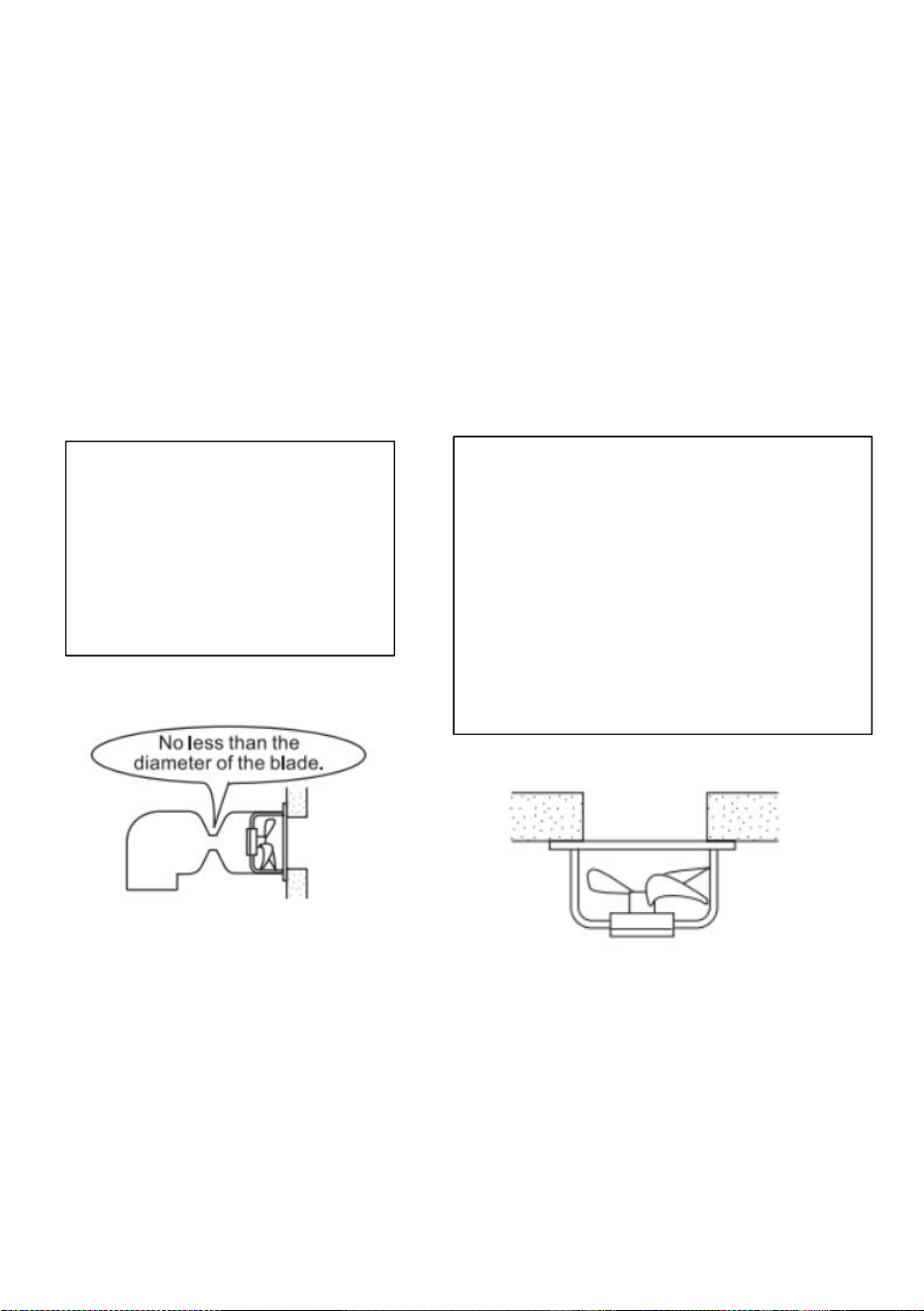
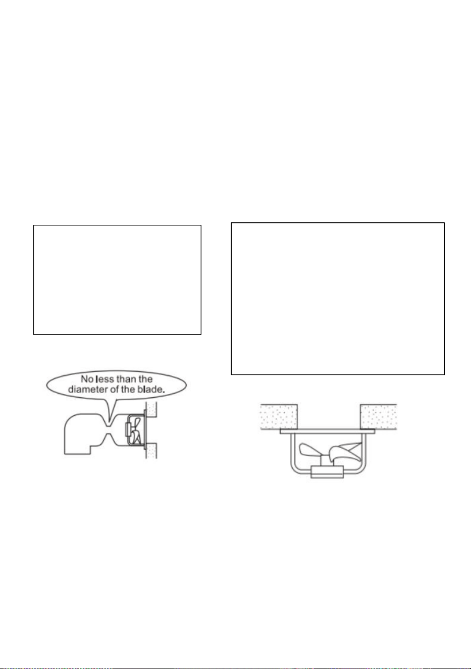
SUGGESTIONS
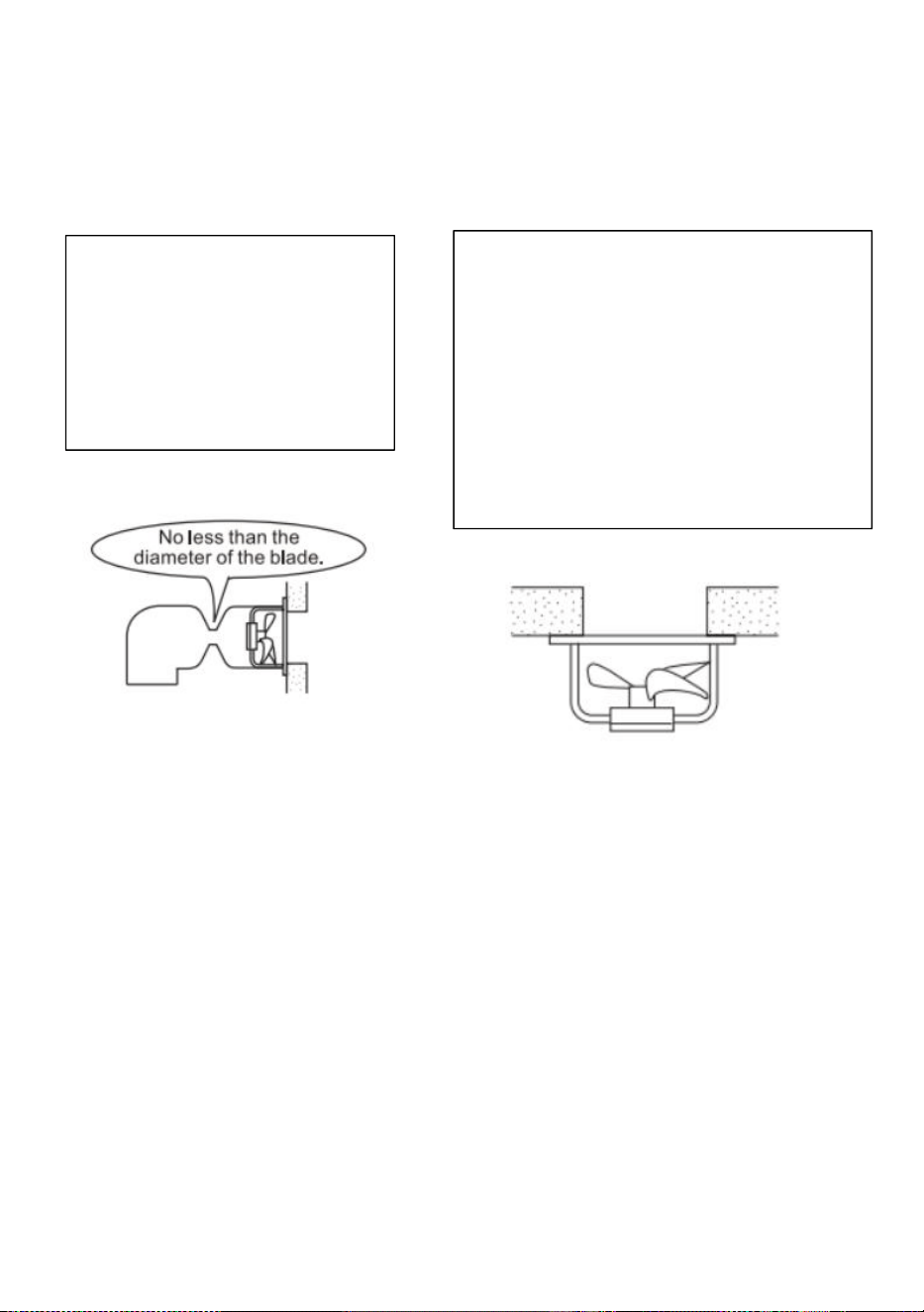
1.Screws can be used to fix
the fan to the wall.
2.If a base is not requested,
just use a tool to unscrew
the screws on the base.
3. Do not install the product in a place
where it may come into direct contact
with water, which may cause malfunction.
4.If the motor shaft is vertical, install the
motor so that it is on the lower side.
Otherwise, it may cause the motor to
malfunction.
7
8
Operating Instruction
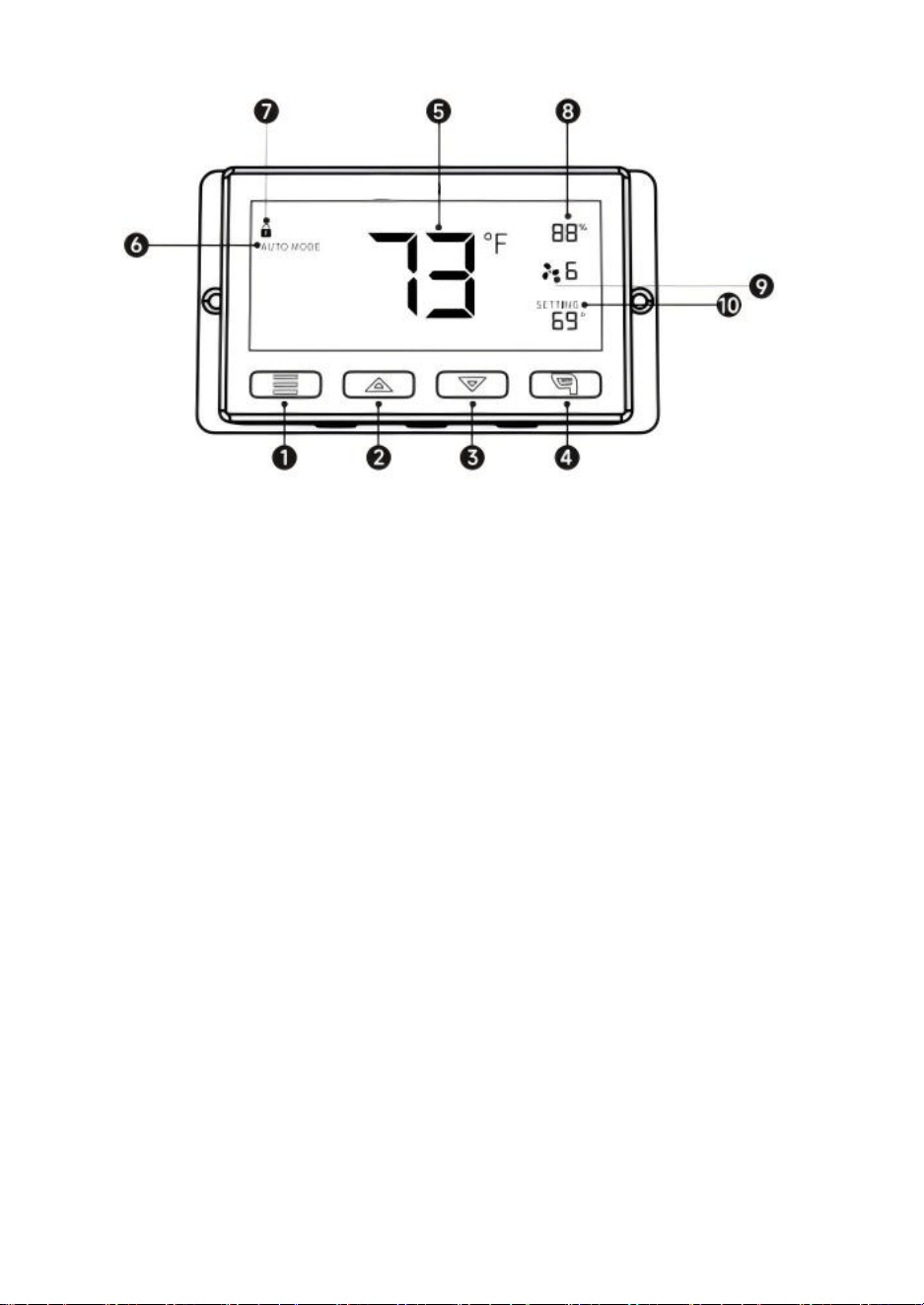
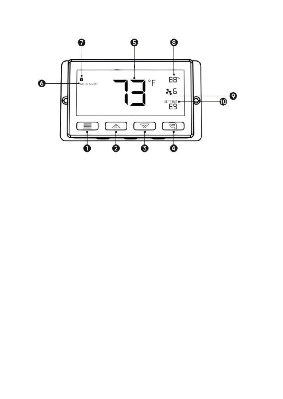
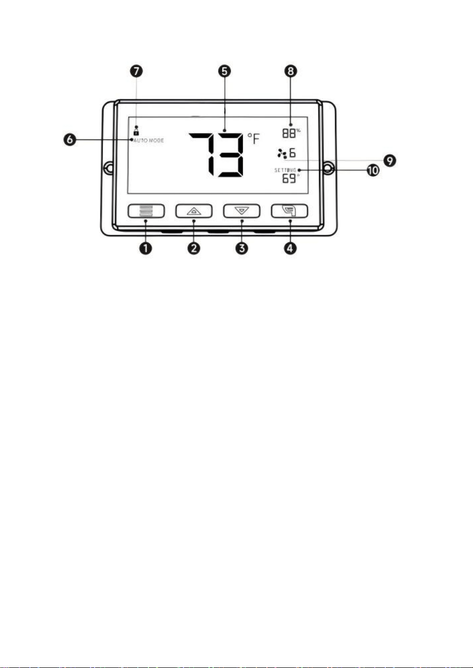
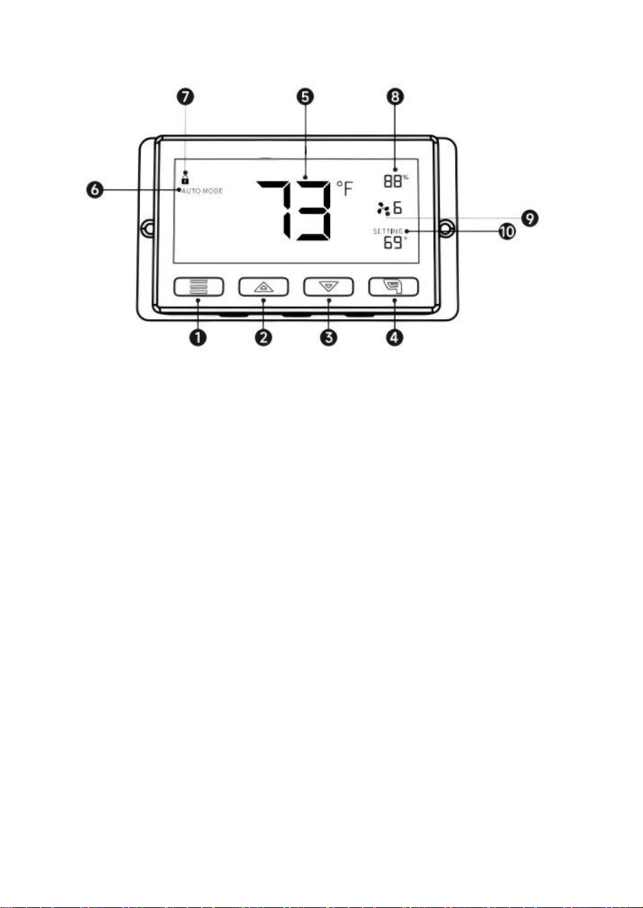
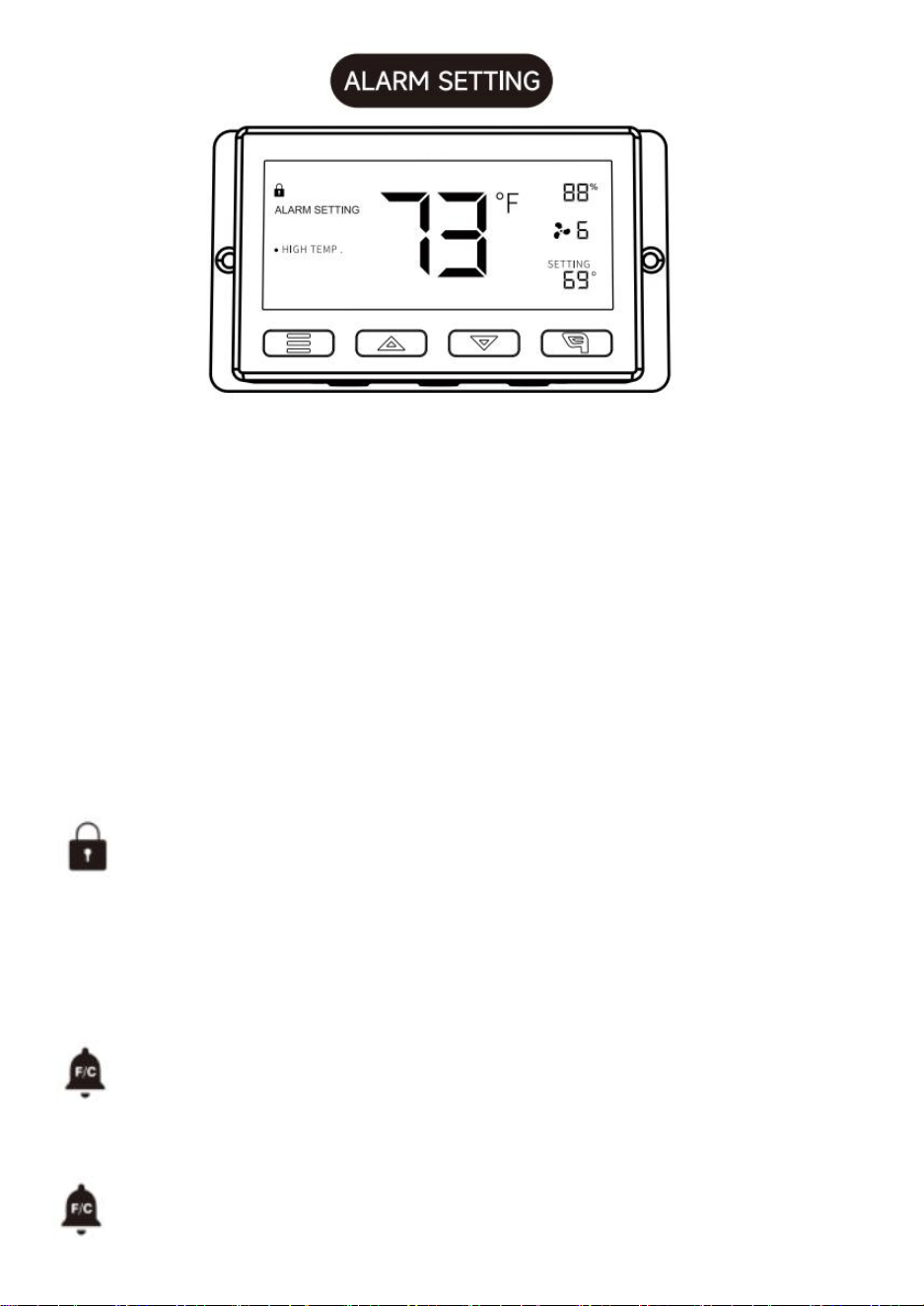
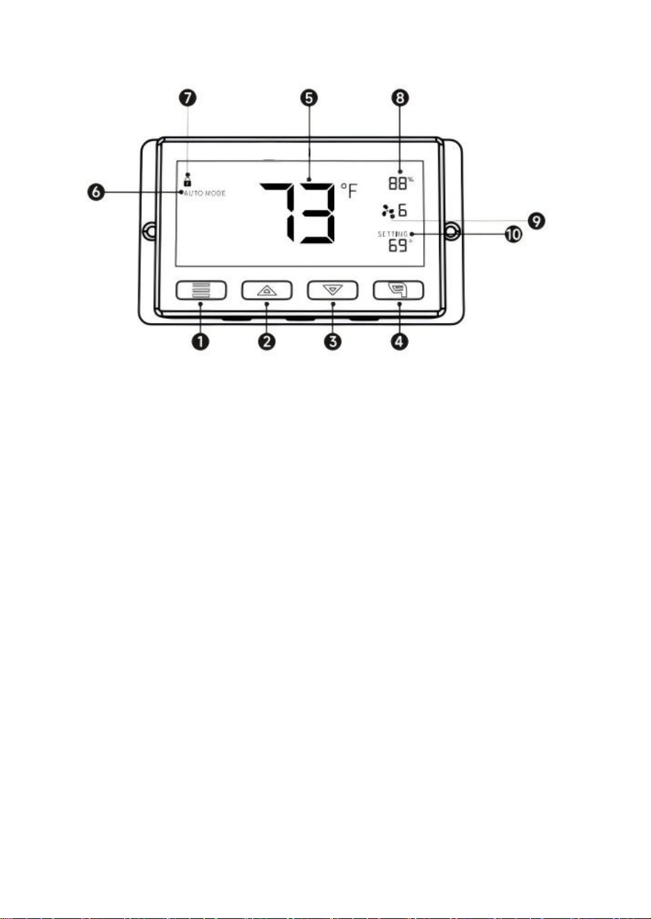
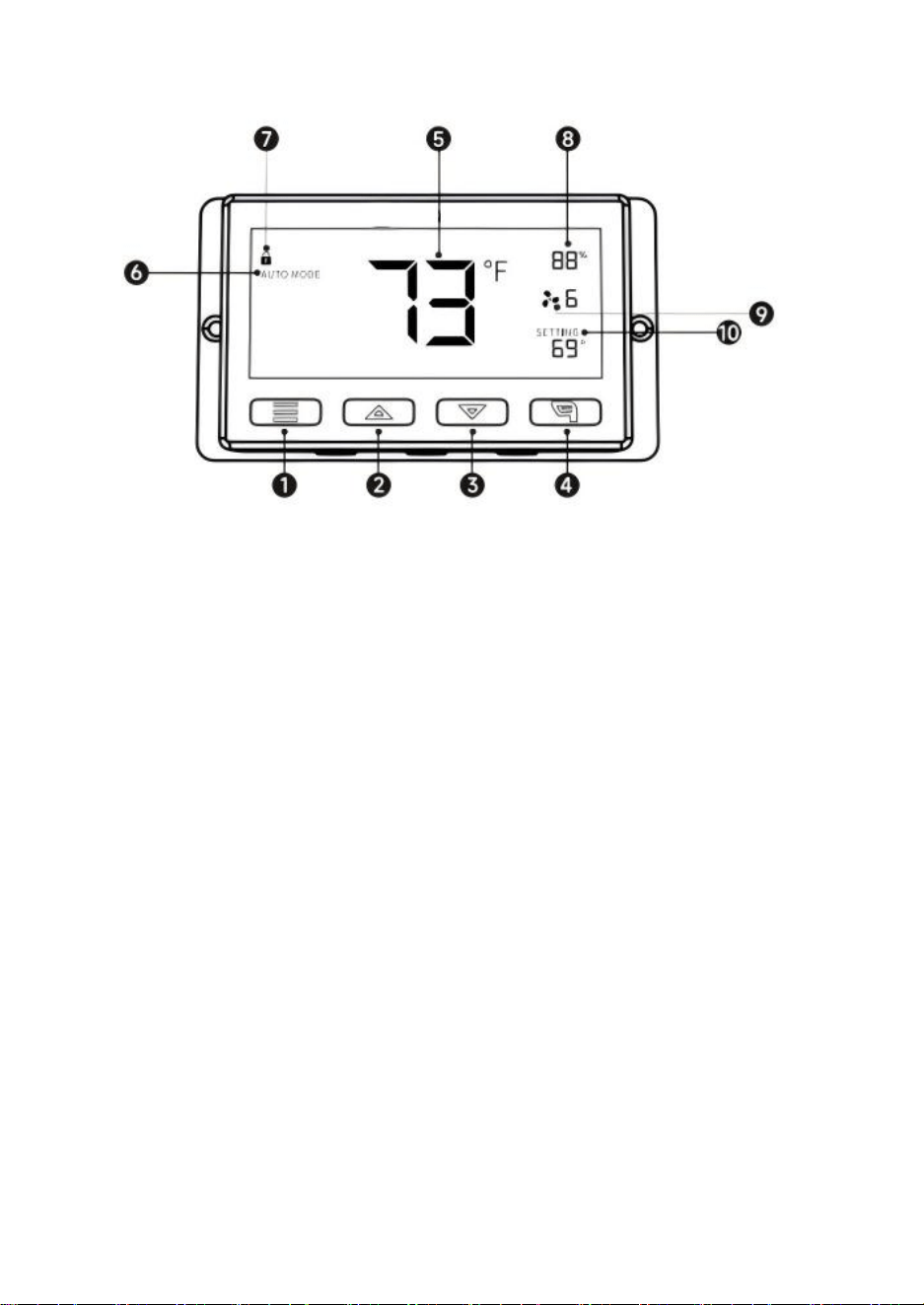
ITEM EXPLAINATION:
1.MODE BUTTON①
By pressing mode button you can sequentially cycle through the following modes:
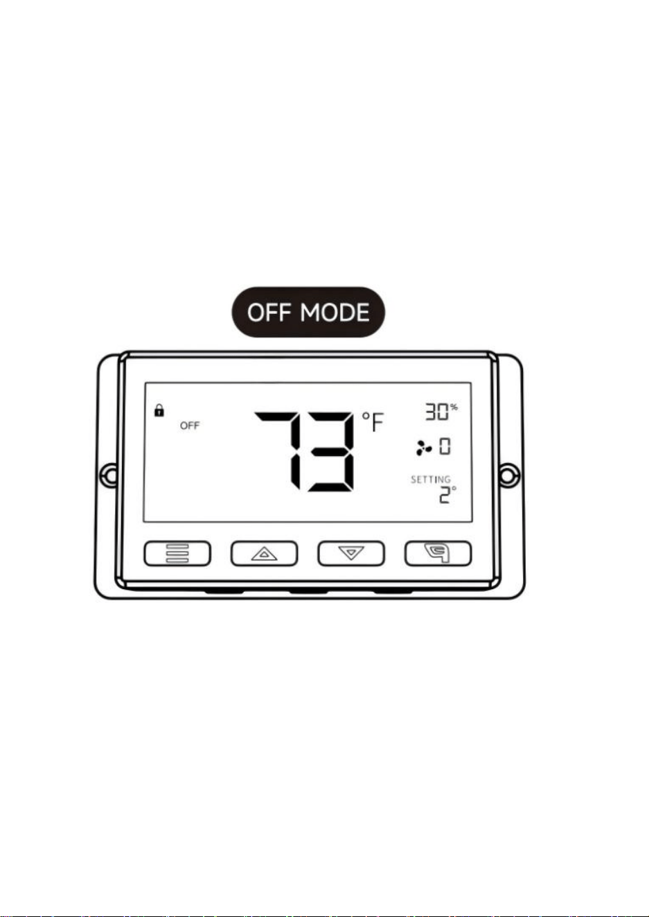
ON MODE, OFF MODE, AUTO MODE, ALARM SETTING and TIMER.
By long pressing the mode button you can return to the previous MODE.
2.UP BUTTON②/DOWN BUTTON③
In any mode, press the up button to increase, press the down button to decrease.
3.LEAF BUTTON④
When the controller is working, the screen can be turned on and off by pressing the
leaf button and the controller can be locked and unlocked by pressing it for 3 seconds.
4.PROBE TEMP⑤/HUMIDITY⑧
Displays the current temperature/humidity as detected by the wired sensor probe.
Please note that if the sensing cable is not plugged in properly, the
temperature/hu-midity value will show "---".
5.CONTROLLER MODE⑥
This area displays the mode that the controller is currently in. Press the Mode Button to
cycle through the modes.
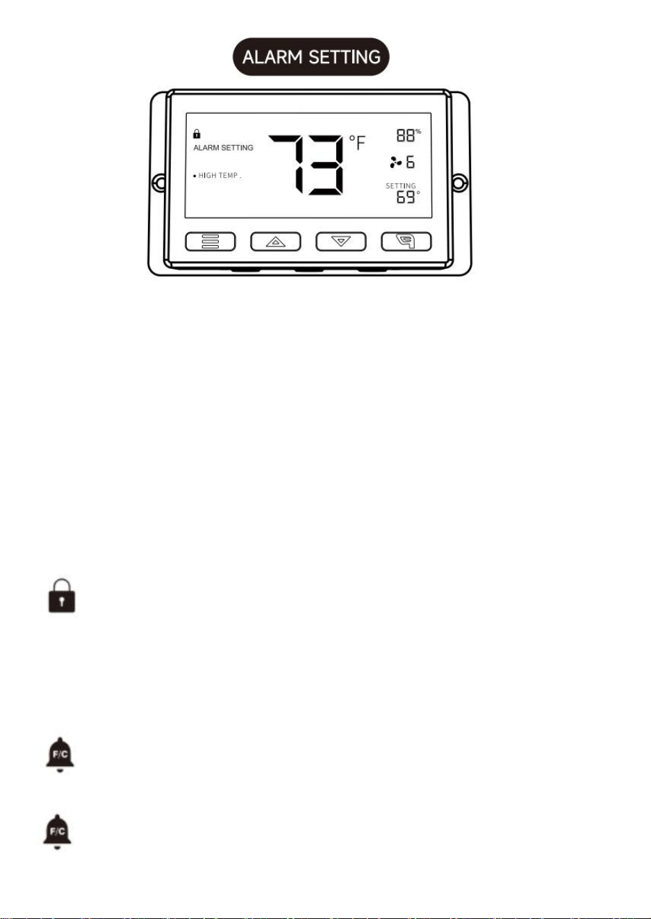
6.ALERT ICONS⑦
This area displays the alerts and statuses from the controller including alarms and
screen lock.
7.FAN SPEED⑨
Displays the current speed the fan is running at.
8.SETTING⑩
Displays the value you have set for the current mode. Press the up or down button to
change.
9
Mode/Setting Explaination
Press the Mode button to cycle through the controller's available
programming modes and settings: ON/OFF Mode, TIMER Mode,
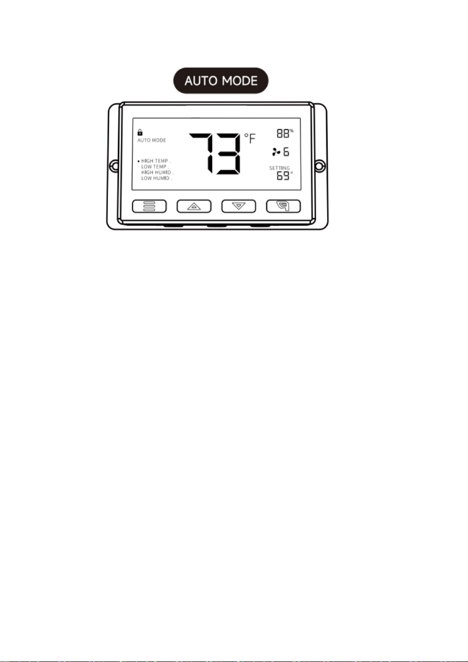
AUTO Mode (4 triggers),
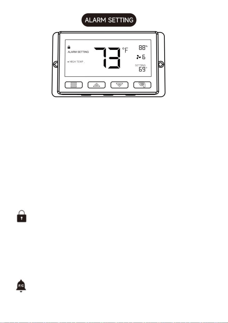
ALARM Settings (4 triggers).
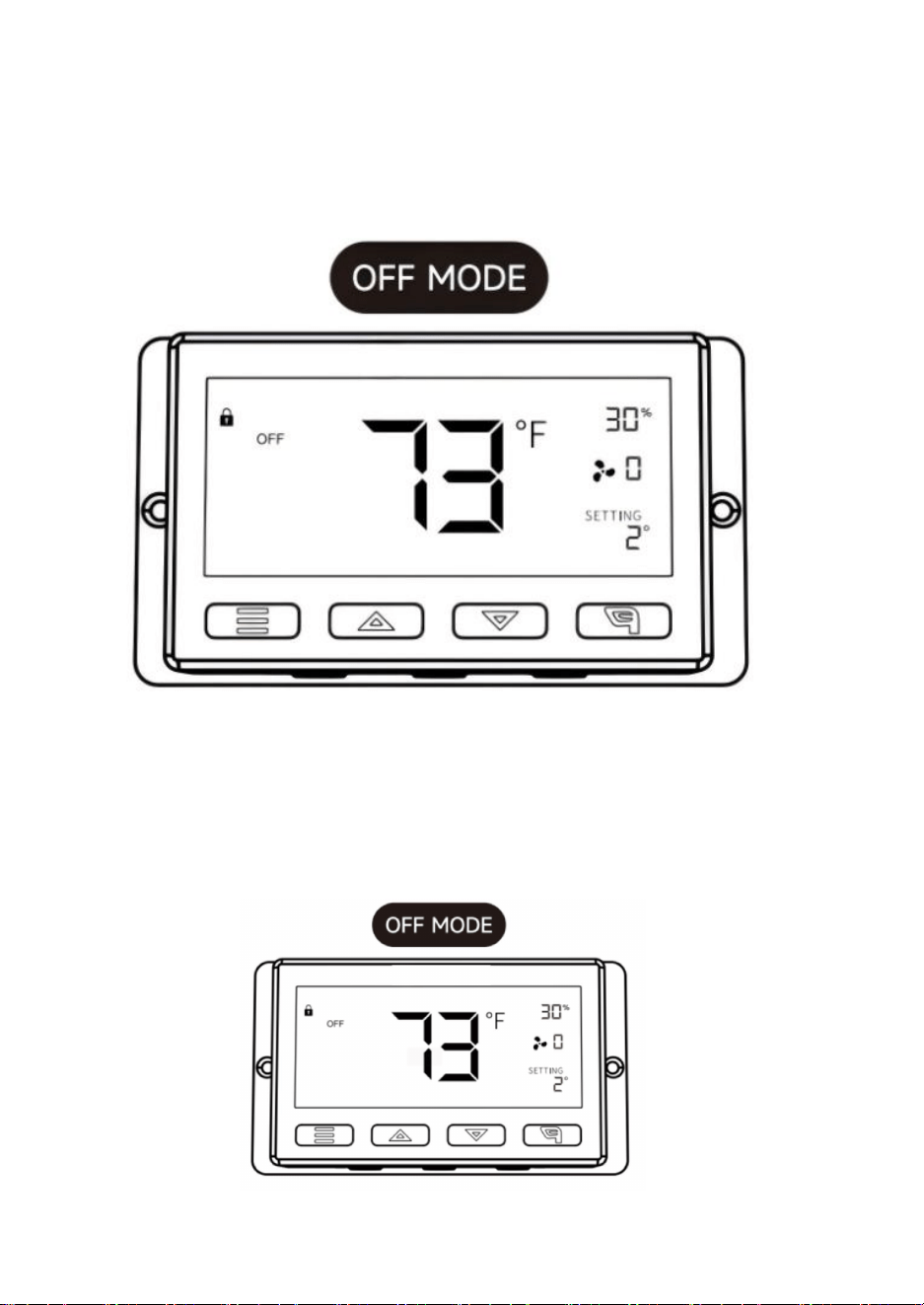
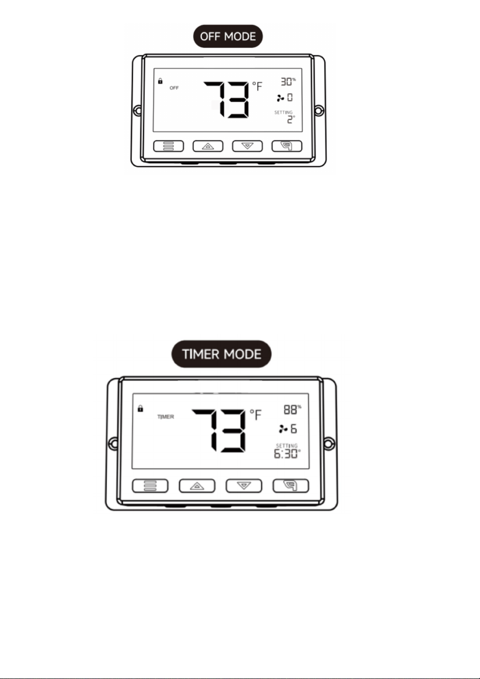
In this mode, the fans will run continuously regardless of temperature
or humidity.And the speed set in this mode will be the max speed the
fans can reach in
AUTO Mode.
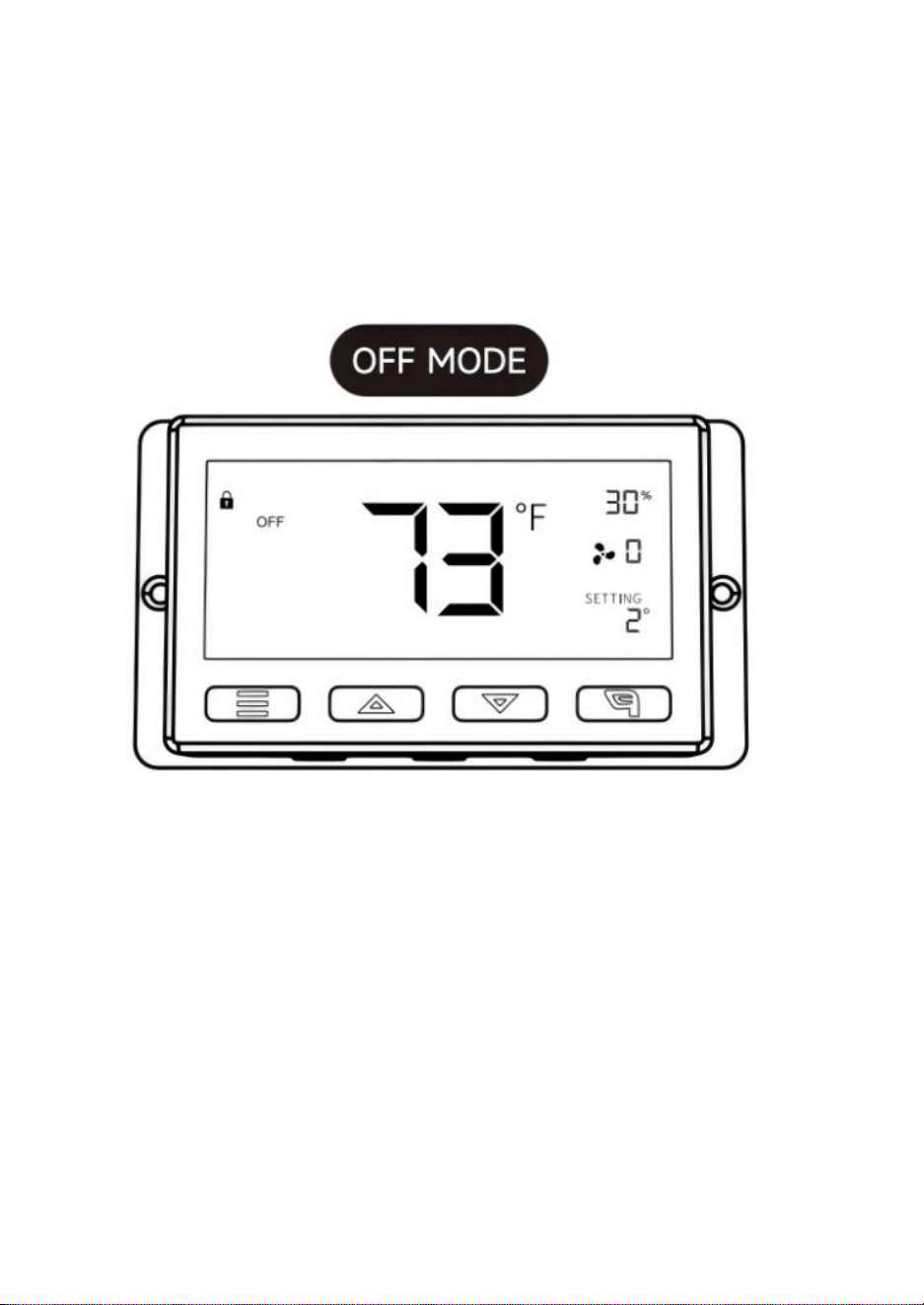
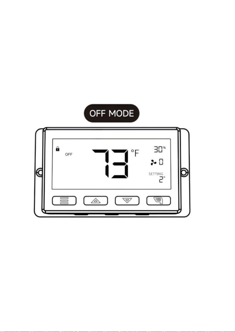
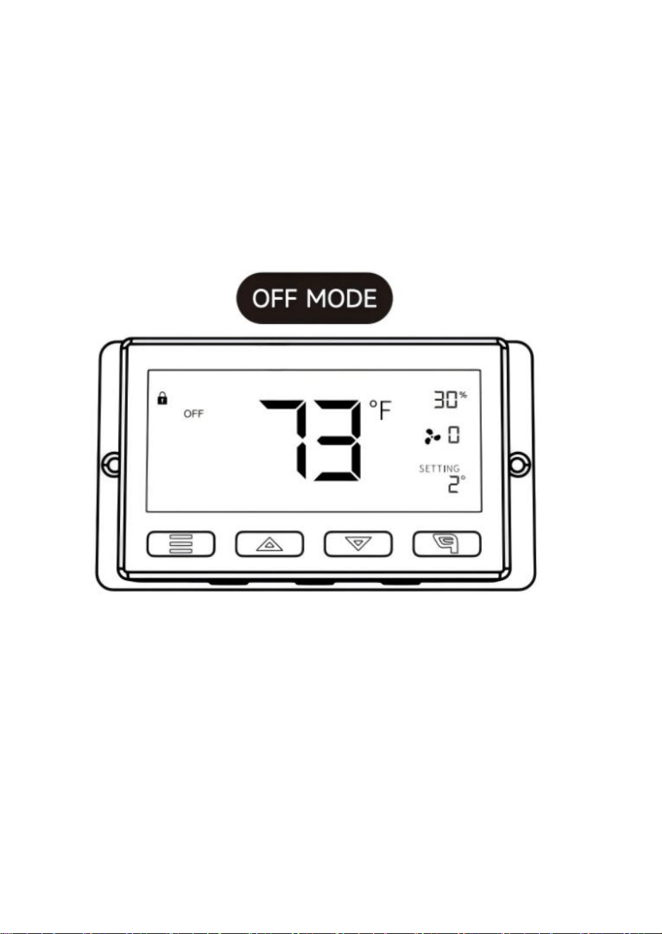
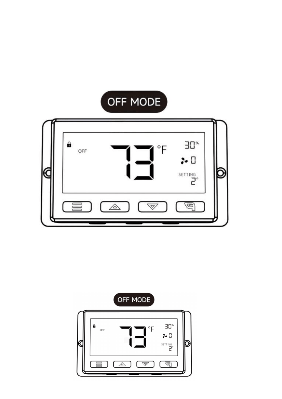
In this mode, the fans will not run regardless of temperature or
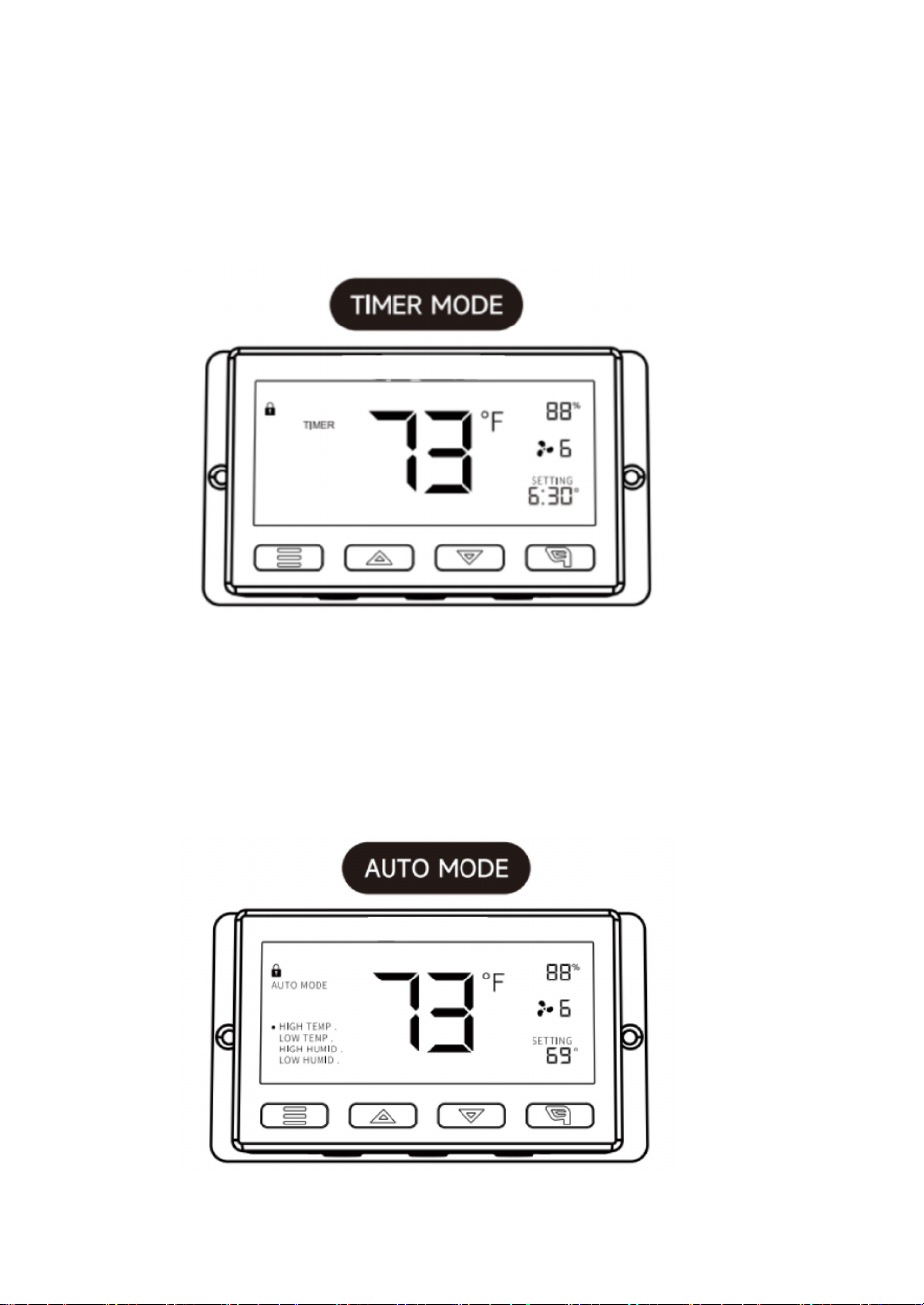
10
humidity. While in this mode,pressing the up or down button will
change the display's brightness.
There are four settings for brightness(Setting:1/2/3/A3). On setting A3,
if the device is left unattended for 30 seconds, the display will
automatically dim its brightness back to setting 1.
Holding up and down button at the same time will cycle through the
temperature unit:
Fahrenheit (°F) and Celsius (°C).
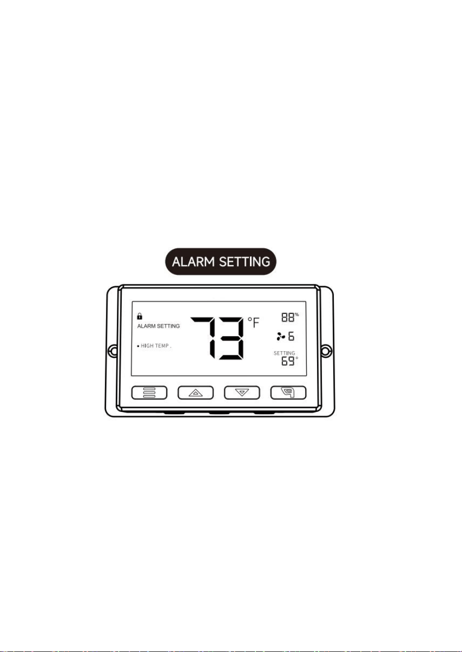
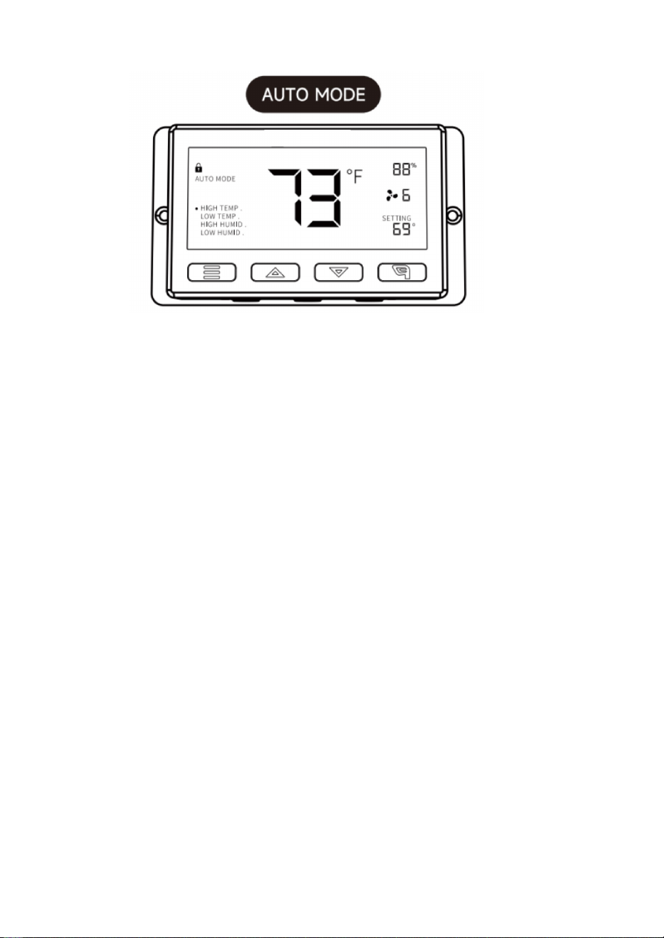
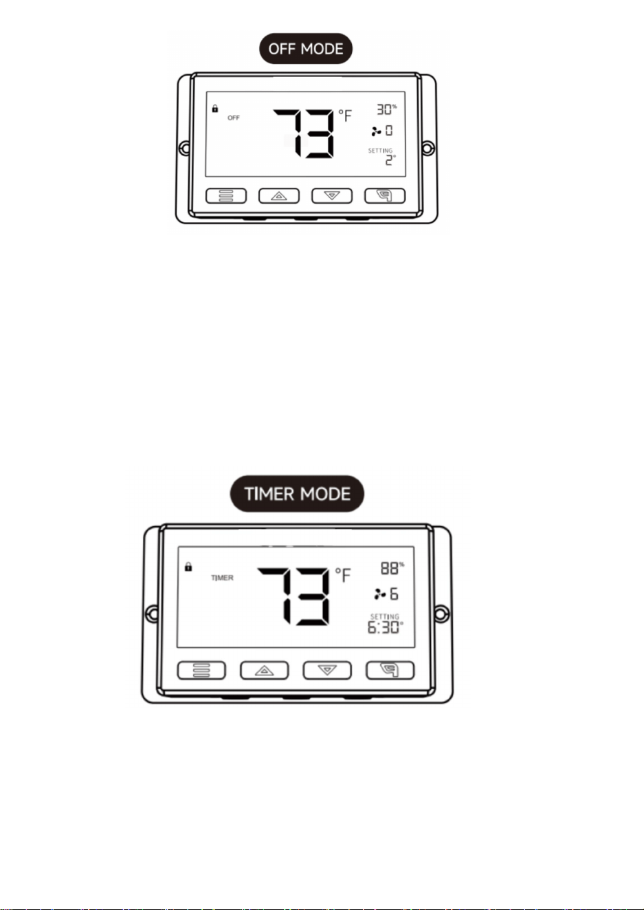
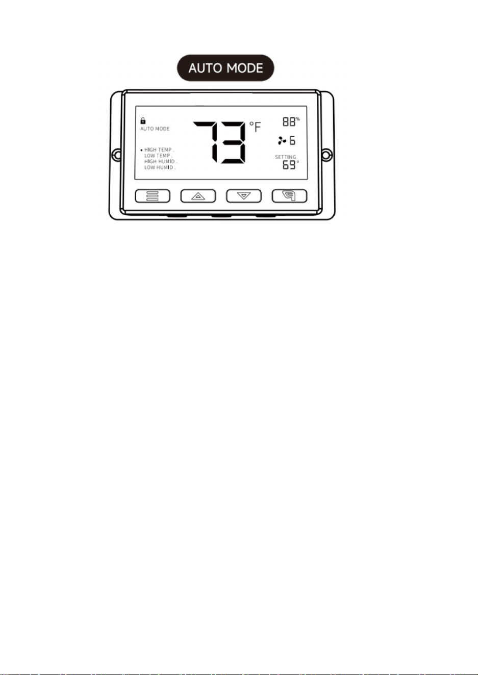
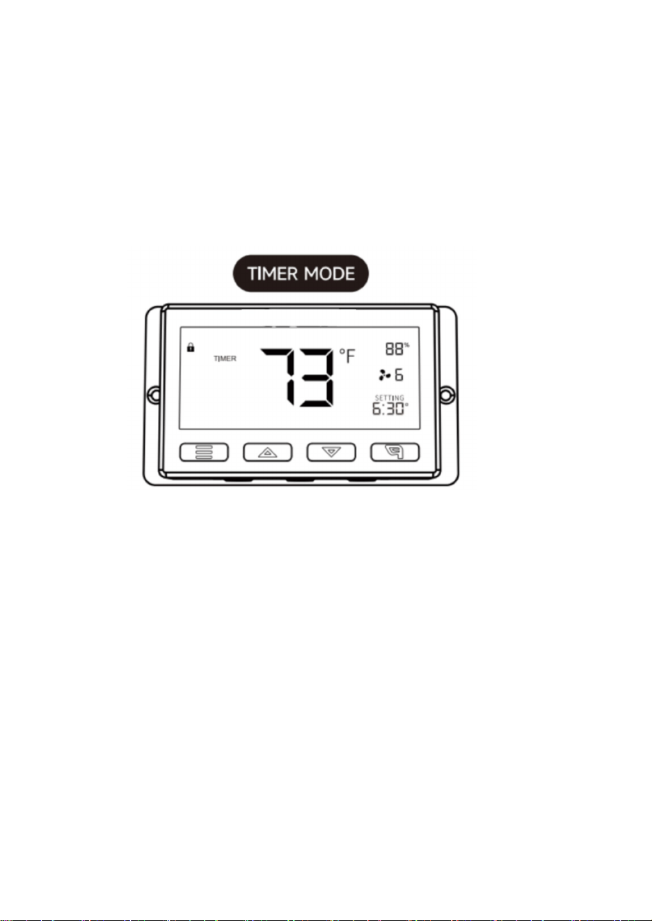
In this mode, press the up or down button to set a time for the timer.
The fans will run at the speed set in ON Mode until the countdown ends.
Afterward, the fan will stop running.
The clock will begin counting down if no buttons are pressed for 3 seconds.
Leaving the timer mode while the countdown is running will pause the clock until you
return to this mode.
11
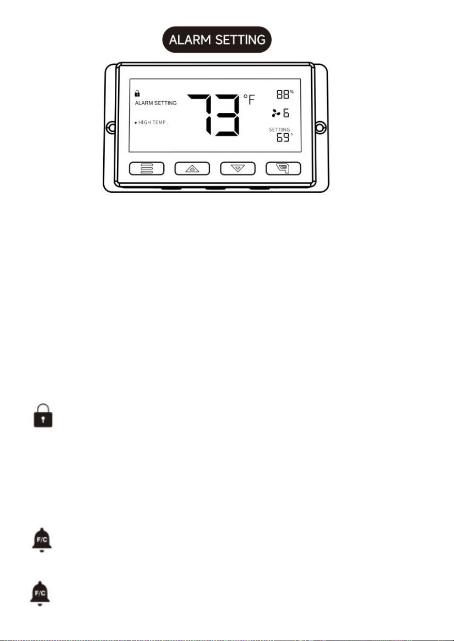
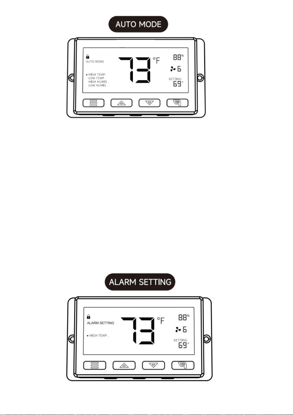
HIGH TEMP:
In this mode, press the up or down button to set a high temperature trigger.
The fans will activate if the probe's measured temperature exceeds the temperature
you have set in this mode. The activated fans will slowly increase in speed until it
reaches the speed set in ON Mode. Whenever the measured temperature falls below
your set temperature, the fans will slowly decrease in speed until the fans stop. You
may also hold the up and down button simultaneously to turn off this trigger, in which
the holder settings will show OFF for off. Note that this trigger can activate to run as
long as you are in AUTO Mode, even if you are in setting up the other AUTO Mode
triggers.
LOW TEMP/HIGH HUMID/LOW HUMID:
The setting method and operating mechanism are the same as the HIGH TEMP trigger
mentioned above.
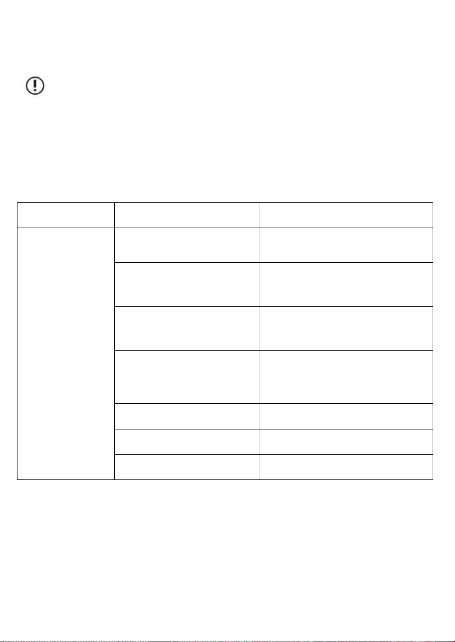
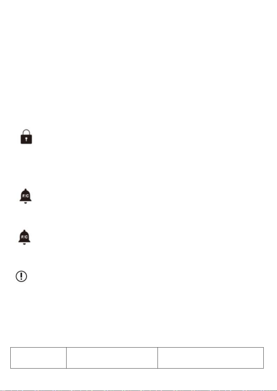
HIGH HUMID:
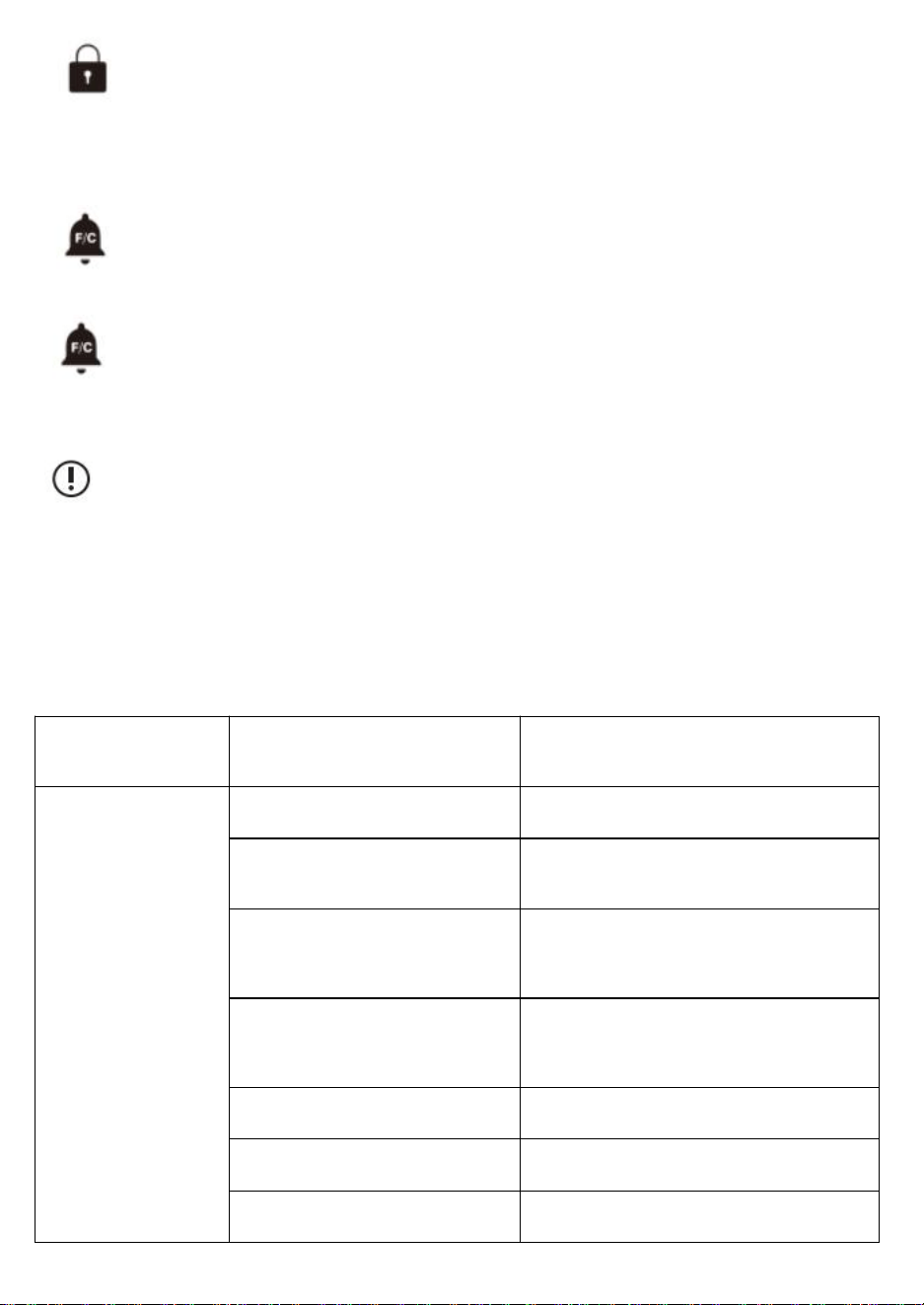
In this settings mode, press the up and down button to set a high humidity alarm.
The alarm will activate if the probe's measured humidity exceeds the humidity you have
set in this mode. When the alarm triggers, the fan will start spinning gradually to max
speed regardless of your other settings. You may also hold the up and down button
simultaneously to turn off this alarm setting, in which the digits under settings will
show OFF. You will need to be in AUT. ON or TIMER mode for this alarm to be able to
activate.
HIGH TEMP/LOW TEMP/LOW HUMID:
The setting method and operating mechanism are the same as the HIGH HUMID
trigger mentioned above.
12
CONTROLLER LOCK
To lock the controller to prevent settings to be changed accidently, hold the
LEAF button for three or more seconds. While the display is locked, you will
not be able to switch modes or changes any settings. Holding the LEAF
button for three or more seconds will unlock the controller.
TEMPERATURE ALARM ALERT
This icon will flash when the high or low temperature alarm that you have set
has been triggered.
HUMIDITY ALARM ALERT
This icon will flash when the high or low humidity alarm that you have set has
been triggered.
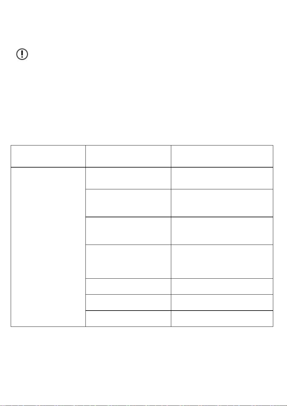
caution:
1.When the equipment causes malfunctions,please self-checking
according to the below items one by one.If you still cannot find the
issues,please get in touch with the dealer or let a professional repair
the product.
2.Please don't self-repair the fan.Improper operation and maintenance
will cause electric shock or fire.
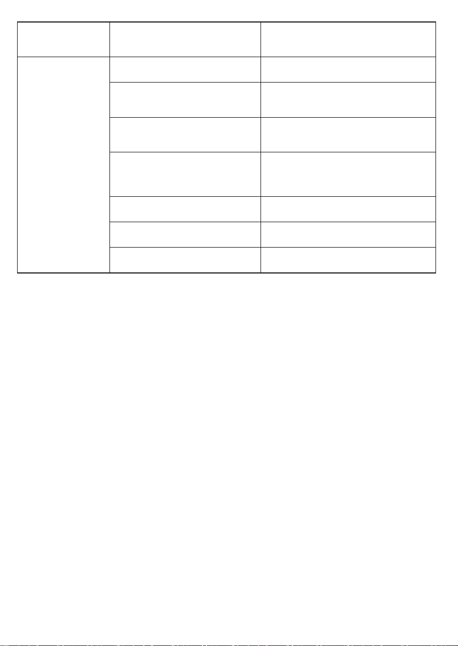
Malfunction
Description
Analysis
Elimination Methods
The fan cannot be
started or operated.
Power outage (self-checking).
Waiting for power source.
The circuit protection device is
tripping (self-checking).
Restart power.
Check whether the voltage is too
high or too low (measured by
professionals).
Check by professionals.
The fan blade is blocked by
foreign objects (self-checking).
Power off and take out the foreign objects.
High-altitude operations should be
operated by professional personnel.
Short circuit.
Check by professionals.
Motor burn.
Check by professionals.
Capacitor burn.
Check by professionals.

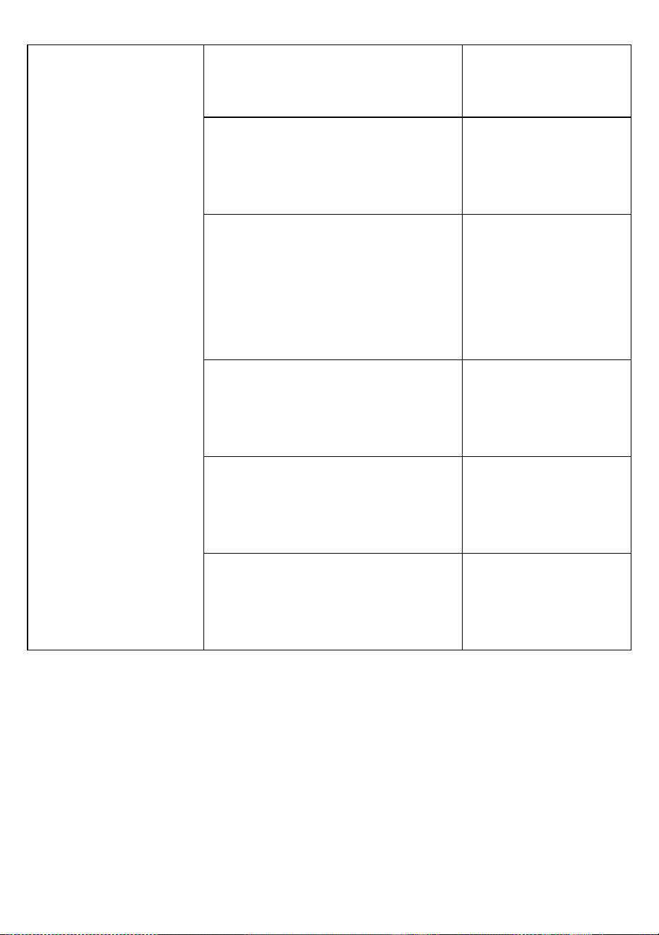
13
The fan causes large
noise and vibration
when it is running.
Not firmly installed
(self-checking).
Reinstallation and
fastening.
The device itself is loose
(self-checking).
Let the professional
fix.
The blade is covered with dust.
Component defects cause the
load changing (self-checking).
Let the professional
fix.
The device is blocked by foreign
objects (self-checking).
Power off and take
out the foreign
objects.
If the device speed increases,
then check whether the voltage is
too high.
Check by
professionals.
If the device speed turns low, then
check whether the voltage is too
low.
Check by
professionals.
Sanven Technology Ltd.
Address: Suite 250, 9166 Anaheim Place, Rancho Cucamonga, CA 91730

14

15
WENTYLATOR WYCIĄGOWY ŻALUZJI
MODEL: HA-300ME/HA-250ME/HA-350ME/HA-400ME

16
1
MODELU:HA-300ME/HA-250ME/HA-350ME/HA-400ME
To jest oryginalna instrukcja obsługi. Przed użyciem prosimy o dokładne
zapoznanie się z treścią instrukcji. Firma VEVOR zastrzega sobie prawo
do jednoznacznej interpretacji niniejszej instrukcji obsługi. Wygląd
produktu zależy od stanu, w jakim go otrzymali Państwo. Prosimy o
wyrozumiałość, ale nie będziemy Państwa ponownie informować o
aktualizacjach technologicznych lub oprogramowania naszego produktu.
Ostrzeżenie: Aby zminimalizować ryzyko obrażeń, użytkownik
powinien uważnie przeczytać instrukcję obsługi.
SHUTTER EXHAUST FAN
2
Specyfikacje
Model
Częstotliwość
napięcia
Moc (W)
HA-300ME
100-240 V~
50/60 Hz
50
HA-250ME
30
HA-350ME
80
HA-400ME
98
Lista akcesoriów
Kabel czujnika temperatury i wilgotności (2,5 m) * 1 , kontroler * 1, kabel audio (3 m) *
1,
śruby * 4 , gumowe przelotki * 4
ŁATWY MONTAŻ:
Wywierć otwory w ścianie i umieść śruby w następujących
pozycjach.
Jednostka: mm
Rozmiar
A
B
Średnica śruby
HA-250ME
269
174
15x9
HA-300ME
312
190
15x9
3
Zamontuj korpus wentylatora.
Przełóż śruby przez osiem otworów montażowych w ramie
zewnętrznej i zabezpiecz je podkładkami i nakrętkami.
Ogłoszenie:
Należy zachować ostrożność, aby nie odkształcić ostrzy podczas
transportu i montażu.
Jeżeli ostrze ulegnie odkształceniu, równowaga ostrza zostanie
HA-350ME
354
235
15x9
HA-400ME
412
220
15 x 9
4
zaburzona, co spowoduje hałas i wibracje.
ROZMIAR PRODUKTU
Jednostka: mm
Rozmiar
A
B
C
D
mi
F
250
314
174
269
170
49
15x9
300
370
190
312
193
56
15x9
350
420
235
354
185
48
15x9
400
480
454
220
221
62
15x9
OSTRZEŻENIE
5
OGŁOSZENIE
Do not disassemble, repair or modify the fan
motor. Otherwise, there is a risk of fire,
electric shock or injury.
Unplug the power plug from the wall outlet
before maintenance, or turn off the circuit
breaker at the switchboard. Otherwise, there
is a risk of electric shock or injury.
Always use at rated voltage. Otherwise,
there is a risk of fire or electric shock.
During operation, do not put fingers or objects
inside the blade. Otherwise, there is a risk of injury.
If the product is not in use for a long time please unplug
the power plug from the socket. Otherwise, there is a risk of
electric shock or fire due to deterioration of insulation.
Wear thick gloves during installation. Cut edges such as
sheet metal, plastic parts, protrusions, or corners of
equipment may cause injury.
6
SUGESTIE
1.Screws can be used to fix
the fan to the wall.
2.If a base is not requested,
just use a tool to unscrew
the screws on the base.
4. Do not install the product in a place
where it may come into direct contact
with water, which may cause malfunction.
4.If the motor shaft is vertical, install the
motor so that it is on the lower side.
Otherwise, it may cause the motor to
malfunction.
7
8
Instrukcja obsługi
WYJAŚNIENIE POZYCJI:
1. PRZYCISK TRYBU①
Naciskając przycisk trybu, można kolejno przełączać się między następującymi trybami:
TRYB WŁ., TRYB WYŁ., TRYB AUTOMATYCZNY, USTAWIANIE ALARMU i TIMER.
Długie naciśnięcie przycisku trybu umożliwia powrót do poprzedniego TRYBU.
2. PRZYCISK GÓRA②/PRZYCISK DÓŁ③
W dowolnym trybie naciśnij przycisk w górę, aby zwiększyć, a przycisk w dół, aby
zmniejszyć.
3. PRZYCISK LIŚCIA④
Podczas pracy sterownika ekran można włączać i wyłączać, naciskając przycisk liścia, a
sterownik można blokować i odblokowywać, naciskając go przez 3 sekundy.
4. SONDA TEMP⑤/WILGOTNOŚĆ⑧
Wyświetla aktualną temperaturę/wilgotność zmierzoną przez przewodową sondę
czujnika.
Należy pamiętać, że jeśli kabel pomiarowy nie jest prawidłowo podłączony, wartość
temperatury/wilgotności będzie wyświetlana jako "---".
5. TRYB KONTROLERA⑥
W tym obszarze wyświetlany jest aktualny tryb pracy kontrolera. Naciskaj przycisk trybu,
aby przełączać tryby.
6. IKONY ALARMÓW⑦
W tym obszarze wyświetlane są alerty i statusy kontrolera, w tym alarmy i blokada
ekranu.
7. PRĘDKOŚĆ WENTYLATORA⑨
Wyświetla aktualną prędkość wentylatora.
8. USTAWIENIA⑩
9
Wyświetla wartość ustawioną dla bieżącego trybu. Naciśnij przycisk w górę lub w dół,
aby zmienić.
Wyjaśnienie trybu/ustawień
Naciśnij przycisk Mode, aby przełączać się między dostępnymi
trybami programowania kontrolera. tryby i ustawienia: tryb WŁ./WYŁ.,
tryb TIMER, tryb AUTO (4 wyzwalacze),
Ustawienia ALARMU (4 wyzwalacze).
W tym trybie wentylatory będą pracować nieprzerwanie, niezależnie
od temperatury i wilgotności. Prędkość ustawiona w tym trybie
będzie maksymalną prędkością, jaką wentylatory mogą osiągnąć.
Tryb AUTO.
10
W tym trybie wentylatory nie będą działać niezależnie od temperatury
i wilgotności. W tym trybie W tym trybie naciśnięcie przycisku w górę
lub w dół spowoduje zmianę jasności wyświetlacza.
Dostępne są cztery ustawienia jasności (ustawienie: 1/2/3/A3). W
przypadku ustawienia A3, jeśli urządzenie jest pozostawiony bez
nadzoru przez 30 sekund, wyświetlacz automatycznie przyciemni
swoją jasność do ustawienia 1.
Jednoczesne przytrzymanie przycisków góra i dół spowoduje
przełączanie jednostek temperatury:
Fahrenheita (°F) i Celsjusza (°C).
W tym trybie naciśnij przycisk w górę lub w dół, aby ustawić czas timera.
Wentylatory będą pracować z prędkością ustawioną w trybie ON do momentu
zakończenia odliczania.
Następnie wentylator zatrzyma się.
Zegar rozpocznie odliczanie, jeśli przez 3 sekundy nie zostanie naciśnięty żaden
przycisk.
11
Opuszczenie trybu timera podczas odliczania spowoduje wstrzymanie zegara do
momentu powrotu do tego trybu.
WYSOKA TEMPERATURA:
W tym trybie naciśnij przycisk w górę lub w dół, aby ustawić wyzwalacz wysokiej
temperatury.
Wentylatory zostaną uruchomione, jeśli zmierzona temperatura sondy przekroczy
temperaturę ustawioną w tym trybie. Aktywowane wentylatory będą powoli zwiększać
prędkość, aż osiągną prędkość ustawioną w trybie ON. Gdy zmierzona temperatura
spadnie poniżej ustawionej temperatury, wentylatory będą powoli zwalniać, aż się
zatrzymają. Możesz również jednocześnie przytrzymać przyciski w górę i w dół, aby
wyłączyć ten wyzwalacz. W takim przypadku ustawienia uchwytu będą wyświetlać OFF
(wyłączony). Należy pamiętać, że ten wyzwalacz może być aktywowany tak długo, jak
długo jesteś w trybie AUTO, nawet jeśli konfigurujesz inne wyzwalacze trybu AUTO.
NISKA TEMPERATURA/WYSOKA WILGOTNOŚĆ/NISKA WILGOTNOŚĆ:
Sposób ustawiania i mechanizm działania są takie same, jak w przypadku
wspomnianego powyżej wyzwalacza WYSOKIEJ TEMPERATURY.
12
WYSOKA WILGOTNOŚĆ:
W tym trybie ustawień naciśnij przycisk w górę i w dół, aby ustawić alarm wysokiej
wilgotności.
Alarm zostanie aktywowany, jeśli zmierzona przez sondę wilgotność przekroczy
wartość ustawioną w tym trybie. Po uruchomieniu alarmu wentylator zacznie
stopniowo obracać się z maksymalną prędkością, niezależnie od pozostałych ustawień.
Możesz również jednocześnie przytrzymać przyciski w górę i w dół, aby wyłączyć to
ustawienie alarmu. Cyfry pod ustawieniami będą wtedy wyświetlać WYŁ. Aby
aktywować ten alarm, musisz być w trybie AUT. ON lub TIMER.
WYSOKA TEMPERATURA/NISKA TEMPERATURA/NISKA WILGOTNOŚĆ:
Sposób ustawiania i mechanizm działania są takie same, jak w przypadku
wspomnianego powyżej wyzwalacza WYSOKIEJ WILGOTNOŚCI.
BLOKADA KONTROLERA
Aby zablokować kontroler i zapobiec przypadkowej zmianie ustawień,
przytrzymaj
przycisk LEAF przez co najmniej trzy sekundy. Gdy wyświetlacz jest
zablokowany,
nie będzie można przełączać trybów ani zmieniać ustawień. Przytrzymanie
przycisku LEAF przez co najmniej trzy sekundy spowoduje odblokowanie
kontrolera.
ALARM TEMPERATURY Ta ikona będzie migać, gdy
uruchomiony zostanie ustawiony alarm wysokiej lub niskiej temperatury .
ALARM WILGOTNOŚCI
Ta ikona będzie migać, gdy uruchomiony zostanie ustawiony alarm wysokiej lub
13
niskiej wilgotności
.
ostrożność:
1. Jeśli sprzęt powoduje awarię, należy przeprowadzić samodzielną
kontrolę, po kolei wykonując czynności opisane poniżej. Jeśli nadal nie
można znaleźć przyczyny problemu, należy skontaktować się ze
sprzedawcą lub zlecić naprawę produktu specjaliście.
2. Nie należy samodzielnie naprawiać wentylatora. Niewłaściwa obsługa
i konserwacja może spowodować porażenie prądem lub pożar.
Opis usterki
Analiza
Metody eliminacji
Nie można
uruchomić ani
obsługiwać
wentylatora.
Przerwa w dostawie prądu
(samosprawdzanie).
Oczekiwanie na źródło zasilania.
Urządzenie zabezpieczające
obwód jest aktywne (sprawdza
się samoczynnie).
Włącz ponownie zasilanie.
Sprawdź, czy napięcie nie jest za
wysokie lub za niskie (pomiar
przez fachowca).
Sprawdź przez profesjonalistów.
Łopatka wentylatora
zablokowana przez ciała obce
(samosprawdzająca się).
Wyłącz zasilanie i usuń ciała obce.
Operacje na dużych wysokościach
powinny być wykonywane przez
wykwalifikowany personel.
Zwarcie.
Sprawdź przez profesjonalistów.
Spalenie silnika.
Sprawdź przez profesjonalistów.
Spalenie kondensatora.
Sprawdź przez profesjonalistów.

14
Pracujący
wentylator
wytwarza duży
hałas i wibracje.
Nie jest solidnie zainstalowany
(sprawdza się samoczynnie).
Ponowny montaż i
mocowanie.
Urządzenie samo w sobie jest
luźne (sprawdza się
samoczynnie).
Pozwól naprawić
problem
profesjonaliście.
Ostrze pokryte jest pyłem. Wady
podzespołów powodują zmianę
obciążenia (samokontrola).
Pozwól naprawić
problem
profesjonaliście.
Urządzenie jest zablokowane
przez ciała obce
(samosprawdzanie).
Wyłącz zasilanie i
wyjmij obce
przedmioty.
Jeżeli prędkość urządzenia
wzrasta, należy sprawdzić, czy
napięcie nie jest za wysokie.
Sprawdź przez
profesjonalistów.
Jeżeli prędkość urządzenia jest
niska, należy sprawdzić, czy
napięcie nie jest za niskie.
Sprawdź przez
profesjonalistów.
Sanven Technology Ltd.
Adres: Apartament 250, 9166 Anaheim Place, Rancho Cucamonga, CA
91730

15

16
ABLUFTVENTILATOR MIT JALOUSIE
MODELL: HA-300ME/HA-250ME/HA-350ME/HA-400ME

17
1
MODELL: HA-300ME/HA-250ME/HA-350ME/HA-400ME
Dies ist die Originalanleitung. Bitte lesen Sie alle Anweisungen sorgfältig
durch, bevor Sie das Gerät in Betrieb nehmen. VEVOR behält sich eine
klare Auslegung unserer Bedienungsanleitung vor. Das Aussehen des
Produkts hängt vom gelieferten Produkt ab. Bitte haben Sie Verständnis
dafür, dass wir Sie nicht erneut über Technologie- oder Software-Updates
informieren.
Warnung: Um das Verletzungsrisiko zu verringern, muss der
Benutzer die Bedienungsanleitung sorgfältig lesen.
SHUTTER EXHAUST FAN
2
Technische Daten
Modell
Spannung
Frequenz
Leistung (W)
HA-300ME
100-240 V~
50/60 Hz
50
HA-250ME
30
HA-350ME
80
HA-400ME
98
Zubehörliste
Temperatur- und Feuchtigkeitssensorkabel (2,5 m) *1 , Controller *1 Audiokabel (3 m)
*1
Schrauben *4 , Gummitüllen *4
EINFACHE MONTAGE:
Bohren Sie Löcher in die Wand und setzen Sie die Bolzen an den
folgenden Positionen ein.
Einheit: mm
Größe
A
B
Bolzendurchmesser
HA-250ME
269
174
15 x 9
HA-300ME
312
190
15 x 9
3
Installieren Sie das Lüftergehäuse.
Führen Sie die Schrauben durch die acht Befestigungslöcher am
Außenrahmen und befestigen Sie sie mit Unterlegscheiben und
Muttern.
Beachten:
Achten Sie darauf, die Klingen während des Transports und der
Installation nicht zu verformen.
HA-350ME
354
235
15 x 9
HA-400ME
412
220
15 x 9
4
Wenn die Klinge verformt ist, wird ihr Gleichgewicht gestört, was zu
Lärm und Vibrationen führt.
PRODUKTGRÖSSE
Einheit: mm
Größe
A
B
C
D
E
F
250
314
174
269
170
49
15 x 9
300
370
190
312
193
56
15 x 9
350
420
235
354
185
48
15 x 9
400
480
454
220
221
62
15 x 9
WARNUNG
5
BEACHTEN
Do not disassemble, repair or modify the fan
motor. Otherwise, there is a risk of fire,
electric shock or injury.
Unplug the power plug from the wall outlet
before maintenance, or turn off the circuit
breaker at the switchboard. Otherwise, there
is a risk of electric shock or injury.
Always use at rated voltage. Otherwise,
there is a risk of fire or electric shock.
During operation, do not put fingers or objects
inside the blade. Otherwise, there is a risk of injury.
If the product is not in use for a long time please unplug
the power plug from the socket. Otherwise, there is a risk of
electric shock or fire due to deterioration of insulation.
Wear thick gloves during installation. Cut edges such as
sheet metal, plastic parts, protrusions, or corners of
equipment may cause injury.
6
VORSCHLÄGE
1.Screws can be used to fix
the fan to the wall.
2.If a base is not requested,
just use a tool to unscrew
the screws on the base.
5. Do not install the product in a place
where it may come into direct contact
with water, which may cause malfunction.
4.If the motor shaft is vertical, install the
motor so that it is on the lower side.
Otherwise, it may cause the motor to
malfunction.
7
8
Bedienungsanleitung
ELEMENTERKLÄRUNG:
1. MODUS-TASTE ①
Durch Drücken der Modus-Taste können Sie nacheinander durch die folgenden Modi
schalten:
EIN-MODUS, AUS-MODUS, AUTO-MODUS, ALARMEINSTELLUNG und TIMER.
Durch langes Drücken der Modus-Taste gelangen Sie zum vorherigen MODUS zurück.
2. AUF-TASTE ②/AB-TASTE ③
Drücken Sie in jedem Modus die Auf-Taste, um den Wert zu erhöhen, und die Ab-Taste,
um ihn zu verringern.
3. BLATT-TASTE ④
Wenn der Controller in Betrieb ist, kann der Bildschirm durch Drücken der Blatt-Taste
ein- und ausgeschaltet und der Controller durch 3-sekündiges Drücken gesperrt und
entsperrt werden.
4. FÜHLERTEMPERATUR ⑤/FEUCHTIGKEIT ⑧
Zeigt die aktuelle Temperatur/Luftfeuchtigkeit an, wie sie vom kabelgebundenen
Sensorfühler erfasst wird.
Bitte beachten Sie, dass der Temperatur-/Luftfeuchtigkeitswert „---“ anzeigt, wenn das
Sensorkabel nicht richtig eingesteckt ist.
5. STEUERUNGSMODUS ⑥
Dieser Bereich zeigt den aktuellen Modus der Steuerung an. Drücken Sie die
Modustaste, um durch die Modi zu blättern.
6. WARNSYMBOLE ⑦
Dieser Bereich zeigt die Warnungen und Status der Steuerung an, einschließlich Alarme
und Bildschirmsperre.
7. LÜFTERDREHZAHL ⑨
9
Zeigt die aktuelle Geschwindigkeit des Lüfters an.
8. EINSTELLUNG ⑩
Zeigt den Wert an, den Sie für den aktuellen Modus eingestellt haben. Drücken Sie zum
Ändern die Auf- oder Ab-Taste.
Modus/Einstellung Erklärung
Drücken Sie die Modus-Taste, um durch die verfügbaren
Programmierungen des Controllers zu blättern Modi und
Einstellungen: EIN/AUS-Modus, TIMER-Modus, AUTO-Modus (4
Auslöser),
ALARM-Einstellungen (4 Auslöser).
In diesem Modus laufen die Lüfter kontinuierlich, unabhängig von
Temperatur oder Luftfeuchtigkeit. Die in diesem Modus eingestellte
Geschwindigkeit ist die maximale Geschwindigkeit, die die Lüfter
erreichen können.
AUTO-Modus.
10
In diesem Modus laufen die Lüfter unabhängig von Temperatur und
Luftfeuchtigkeit nicht. In diesem Im Modus „Auf“ oder „Ab“ wird
durch Drücken der Auf- oder Ab-Taste die Helligkeit des Displays
geändert.
Es gibt vier Helligkeitseinstellungen (Einstellung: 1/2/3/A3). Bei
Einstellung A3, wenn das Gerät Wenn das Display 30 Sekunden lang
unbeaufsichtigt bleibt, wird die Helligkeit automatisch wieder
gedimmt auf Stufe 1.
Durch gleichzeitiges Halten der Auf- und Ab-Tasten können Sie
zwischen den Temperatureinheiten wechseln:
Fahrenheit (°F) und Celsius (°C).
Drücken Sie in diesem Modus die Auf- oder Ab-Taste, um eine Zeit für den Timer
einzustellen.
Die Ventilatoren laufen mit der im EIN-Modus eingestellten Geschwindigkeit, bis der
Countdown abgelaufen ist.
Danach stoppt der Ventilator.
Die Uhr beginnt herunterzuzählen, wenn 3 Sekunden lang keine Taste gedrückt wird.
11
Wenn
Sie den Timer-Modus während des Countdowns verlassen, wird die Uhr angehalten, bis
Sie in diesen Modus zurückkehren.
HOHE TEMPERATUR:
Drücken Sie in diesem Modus die Auf- oder Ab-Taste, um einen
Hochtemperaturauslöser einzustellen.
Die Lüfter werden aktiviert, wenn die vom Fühler gemessene Temperatur die in diesem
Modus eingestellte Temperatur überschreitet. Die Drehzahl der aktivierten Lüfter wird
langsam erhöht, bis sie die im EIN-Modus eingestellte Geschwindigkeit erreicht. Sobald
die gemessene Temperatur unter die eingestellte Temperatur fällt, wird die Drehzahl
der Lüfter langsam verringert, bis sie stoppen. Sie können die Auf- und Ab-Taste auch
gleichzeitig gedrückt halten, um diesen Auslöser auszuschalten. In diesem Fall wird in
den Haltereinstellungen „OFF“ für „Aus“ angezeigt. Beachten Sie, dass dieser Auslöser
aktiviert werden kann, solange Sie sich im AUTO-Modus befinden, auch wenn Sie
gerade die anderen Auslöser im AUTO-Modus einrichten.
NIEDRIGE TEMPERATUR/HOHE FEUCHTIGKEIT/NIEDRIGE FEUCHTIGKEIT:
Die Einstellungsmethode und der Betriebsmechanismus sind dieselben wie beim oben
erwähnten HOHE TEMPERATUR-Auslöser.
12
HOHE LUFTFEUCHTIGKEIT:
Drücken Sie in diesem Einstellungsmodus die Auf- und Ab-Taste, um einen Alarm für
hohe Luftfeuchtigkeit einzustellen.
Der Alarm wird aktiviert, wenn die vom Fühler gemessene Luftfeuchtigkeit die von
Ihnen in diesem Modus eingestellte Luftfeuchtigkeit überschreitet. Sobald der Alarm
ausgelöst wird, dreht sich der Ventilator unabhängig von Ihren anderen Einstellungen
allmählich auf Höchstgeschwindigkeit. Sie können die Auf- und Ab-Tasten auch
gleichzeitig gedrückt halten, um diesen Alarm auszuschalten. In diesem Fall wird unter
den Einstellungen „AUS“ angezeigt. Sie müssen sich im Modus „AUT. EIN“ oder
„TIMER“ befinden, damit dieser Alarm aktiviert werden kann.
HOHE TEMPERATUR/NIEDRIGE TEMPERATUR/NIEDRIGE FEUCHTIGKEIT:
Die Einstellungsmethode und der Betriebsmechanismus sind dieselben wie beim oben
erwähnten Auslöser „HOHE FEUCHTIGKEIT“.
CONTROLLER-SPERRE
Um den Controller zu sperren und versehentliche Änderungen der
Einstellungen zu verhindern, halten Sie die
LEAF-Taste mindestens drei Sekunden lang gedrückt. Während das Display
gesperrt ist,
können Sie weder den Modus wechseln noch Einstellungen ändern. Wenn Sie
die LEAF
-Taste mindestens drei Sekunden lang gedrückt halten, wird der Controller
entsperrt.
TEMPERATURALARM
Dieses Symbol blinkt, wenn der von Ihnen eingestellte Hoch- oder
Niedrigtemperaturalarm
ausgelöst wurde.
13
FEUCHTIGKEITSALARM
Dieses Symbol blinkt, wenn der von Ihnen eingestellte Alarm für hohe oder
niedrige Luftfeuchtigkeit
ausgelöst wurde.
Vorsicht:
1.Wenn das Gerät Fehlfunktionen verursacht, überprüfen Sie es bitte
selbst nacheinander anhand der folgenden Punkte. Wenn Sie die
Probleme immer noch nicht finden können, wenden Sie sich bitte an den
Händler oder lassen Sie das Produkt von einem Fachmann reparieren.
2. Reparieren Sie den Ventilator bitte nicht selbst. Unsachgemäße
Bedienung und Wartung können zu Stromschlägen oder Bränden
führen.
Störungsbeschreibung
Analyse
Eliminierungsmethoden
Der Lüfter lässt sich nicht
starten oder bedienen.
Stromausfall
(Selbstüberprüfung).
Warte auf Stromquelle.
Die Schutzeinrichtung des
Stromkreises löst aus
(Selbstüberprüfung).
Starten Sie die Stromversorgung neu.
Prüfen Sie, ob die Spannung
zu hoch oder zu niedrig ist
(von Fachleuten gemessen).
Kontrolle durch Profis.
Das Lüfterblatt ist durch
Fremdkörper blockiert
(Selbstprüfung).
Schalten Sie das Gerät aus und
entfernen Sie die Fremdkörper.
Arbeiten in großen Höhen sollten von
Fachpersonal durchgeführt werden.
Kurzschluss.
Kontrolle durch Profis.
Motorbrand.
Kontrolle durch Profis.
Kondensator durchgebrannt.
Kontrolle durch Profis.

14
Der Lüfter verursacht
im Betrieb große
Geräusche und
Vibrationen.
Nicht fest eingebaut
(selbstprüfend).
Neuinstallation und
Befestigung.
Das Gerät selbst ist lose
(selbstüberprüfend).
Überlassen Sie die
Reparatur dem
Fachmann.
Das Blatt ist mit Staub bedeckt.
Bauteildefekte führen zu
Lastwechseln (Selbstkontrolle).
Überlassen Sie die
Reparatur dem
Fachmann.
Das Gerät ist durch
Fremdkörper blockiert
(Selbstprüfung).
Schalten Sie das
Gerät aus und
entfernen Sie die
Fremdkörper.
Steigt die Geschwindigkeit des
Geräts, prüfen Sie, ob die
Spannung zu hoch ist.
Kontrolle durch Profis.
Wenn die Geschwindigkeit des
Geräts nachlässt, prüfen Sie, ob
die Spannung zu niedrig ist.
Kontrolle durch Profis.
Sanven Technology Ltd.
Adresse: Suite 250, 9166 Anaheim Place, Rancho Cucamonga, CA 91730

15

16
VENTILATEUR D'EXTRACTION À
OBTURATEUR
MODÈLE : HA-300ME/HA-250ME/HA-350ME/HA-400ME

17
1
MODÈLE : HA-300ME/HA-250ME/HA-350ME/HA-400ME
Ceci est le mode d'emploi d'origine. Veuillez lire attentivement l'intégralité
du manuel avant utilisation. VEVOR se réserve le droit d'interpréter
clairement ce manuel d'utilisation. L'apparence du produit dépend du
produit que vous avez reçu. Veuillez nous excuser pour les éventuelles
mises à jour technologiques ou logicielles.
Avertissement - Pour réduire le risque de blessure, l'utilisateur
doit lire attentivement le manuel d'instructions.
SHUTTER EXHAUST FAN
2
Caractéristiques
Modèle
Tension Fréquence
Puissance (W)
HA-300ME
100-240 V~
50/60 Hz
50
HA-250ME
30
HA-350ME
80
HA-400ME
98
Liste des accessoires
Câble de capteur de température et d'humidité (2,5 m) * 1 , contrôleur * 1, câble audio
(3 m) * 1,
vis * 4 , œillets en caoutchouc * 4
FACILE À MONTER :
Percez des trous dans le mur et insérez les boulons dans les
positions suivantes.
Unité : mm
Installer le corps du
ventilateur.
Taille
UN
B
Diamètre du boulon
HA-250ME
269
174
15x9
HA-300ME
312
190
15x9
HA-350ME
354
235
15x9
HA-400ME
412
220
15 x 9
3
Passez les boulons dans les huit trous de montage du cadre extérieur
et fixez-les avec des rondelles et des écrous.
Avis:
Veillez à ne pas déformer les lames lors du transport et de
l'installation.
Si la lame est déformée, l’équilibre de la lame est perturbé, ce qui
provoque du bruit et des vibrations.
TAILLE DU PRODUIT
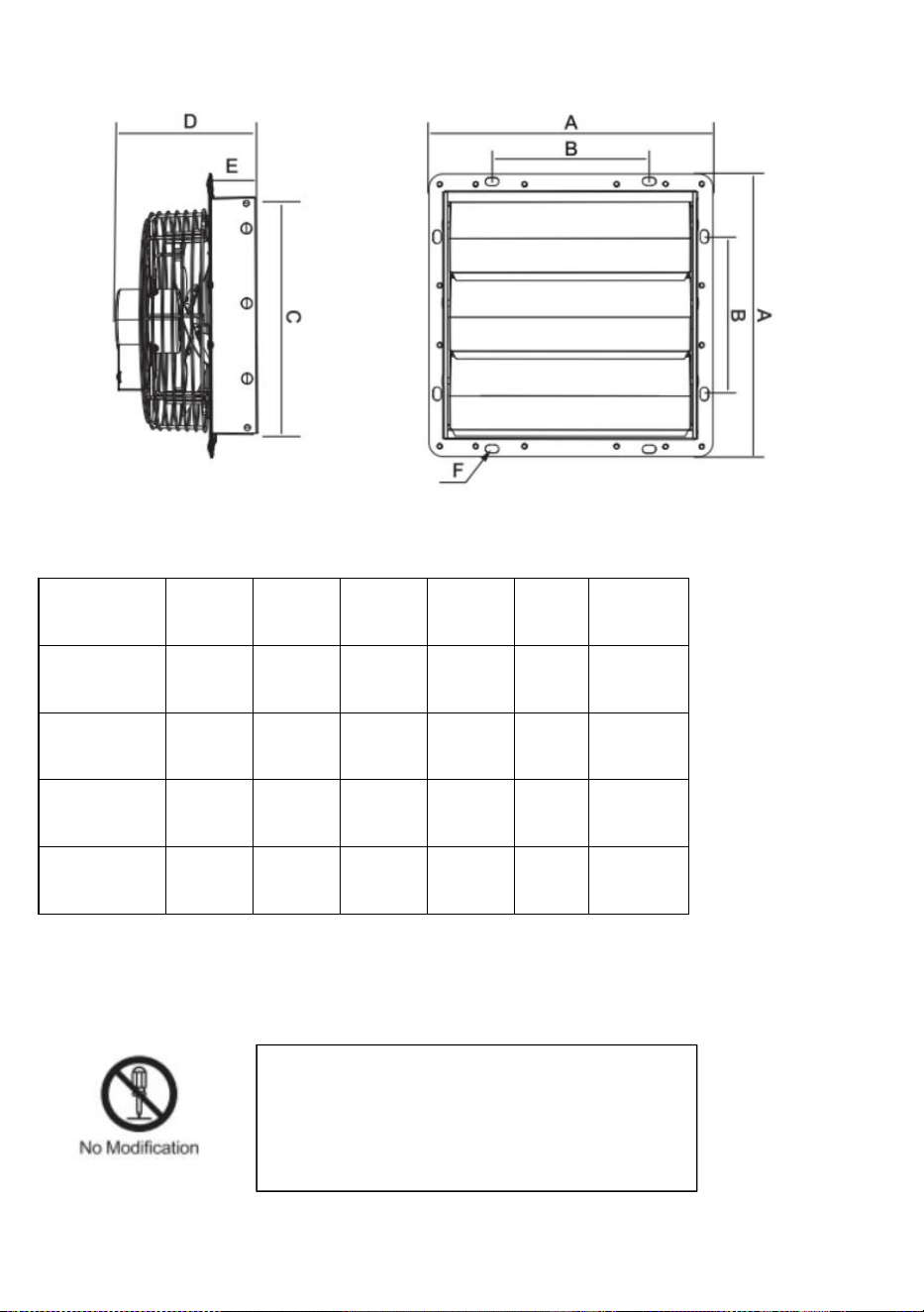
4
Unité : mm
Taille
UN
B
C
D
E
F
250
314
174
269
170
49
15x9
300
370
190
312
193
56
15x9
350
420
235
354
185
48
15x9
400
480
454
220
221
62
15x9
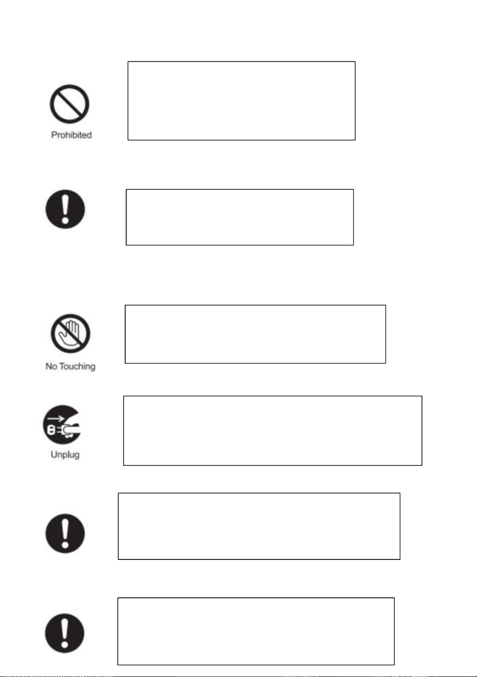
AVERTISSEMENT
Do not disassemble, repair or modify the fan
motor. Otherwise, there is a risk of fire,
electric shock or injury.
5
AVIS
Unplug the power plug from the wall outlet
before maintenance, or turn off the circuit
breaker at the switchboard. Otherwise, there
is a risk of electric shock or injury.
Always use at rated voltage. Otherwise,
there is a risk of fire or electric shock.
During operation, do not put fingers or objects
inside the blade. Otherwise, there is a risk of injury.
If the product is not in use for a long time please unplug
the power plug from the socket. Otherwise, there is a risk of
electric shock or fire due to deterioration of insulation.
Wear thick gloves during installation. Cut edges such as
sheet metal, plastic parts, protrusions, or corners of
equipment may cause injury.
Install the fan firmly in a place where is strong enough,
If not it needs to be reinforced. Otherwise, there is a
risk of falling injury.
6
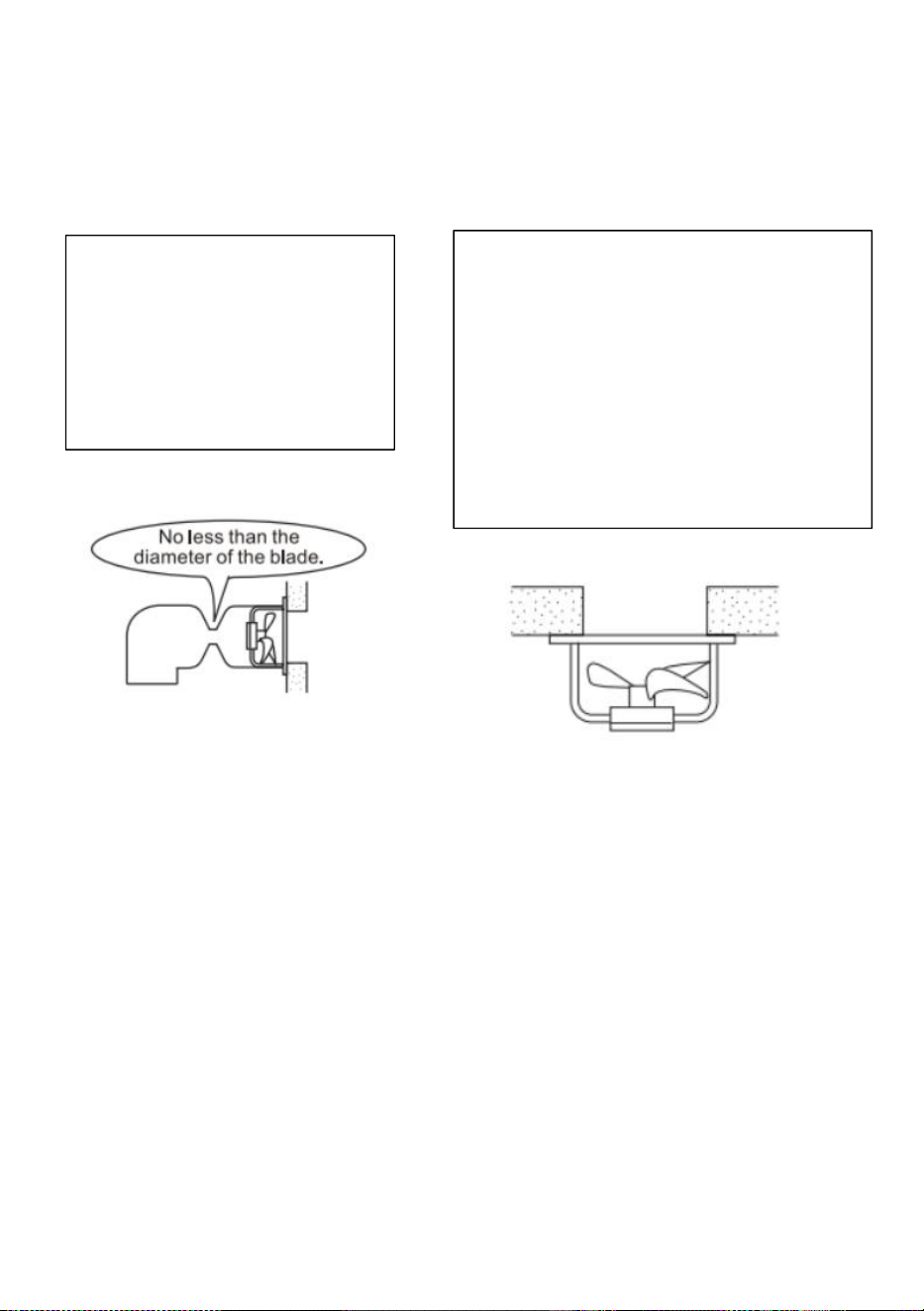
SUGGESTIONS
1.Screws can be used to fix
the fan to the wall.
2.If a base is not requested,
just use a tool to unscrew
the screws on the base.
6. Do not install the product in a place
where it may come into direct contact
with water, which may cause malfunction.
4.If the motor shaft is vertical, install the
motor so that it is on the lower side.
Otherwise, it may cause the motor to
malfunction.
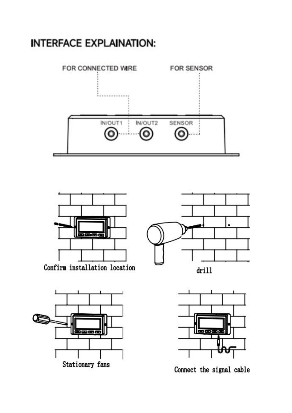
7
8
Mode d'emploi
EXPLICATION DE L'ÉLÉMENT :
1. BOUTON MODE①
En appuyant sur le bouton mode, vous pouvez parcourir séquentiellement les modes
suivants :
MODE MARCHE, MODE ARRÊT, MODE AUTO, RÉGLAGE DE L'ALARME et MINUTERIE.
En appuyant longuement sur le bouton mode, vous pouvez revenir au MODE
précédent.
2. BOUTON HAUT②/BOUTON BAS③
Dans n'importe quel mode, appuyez sur le bouton haut pour augmenter, appuyez sur
le bouton bas pour diminuer.
3. BOUTON FEUILLE④
Lorsque le contrôleur fonctionne, l'écran peut être allumé et éteint en appuyant sur le
bouton feuille et le contrôleur peut être verrouillé et déverrouillé en appuyant dessus
pendant 3 secondes.
4. SONDE TEMP⑤/HUMIDITÉ⑧
Affiche la température/humidité actuelle telle que détectée par la sonde du capteur
filaire.
Veuillez noter que si le câble de détection n'est pas branché correctement, la valeur de
température/humidité affichera « --- ».
5. MODE DU CONTRÔLEUR⑥
Cette zone affiche le mode dans lequel se trouve actuellement le contrôleur. Appuyez
sur le bouton Mode pour parcourir les modes.
6. ICÔNES D'ALERTE⑦
Cette zone affiche les alertes et les statuts du contrôleur, y compris les alarmes et le
verrouillage de l'écran.
9
7. VITESSE DU VENTILATEUR⑨
Affiche la vitesse actuelle à laquelle fonctionne le ventilateur.
8. RÉGLAGE⑩
Affiche la valeur que vous avez définie pour le mode actuel. Appuyez sur le bouton
haut ou bas pour modifier.
Explication du mode/paramètre
Appuyez sur le bouton Mode pour parcourir la programmation
disponible du contrôleur modes et réglages : Mode ON/OFF, Mode
TIMER, Mode AUTO (4 déclencheurs),
Paramètres d'ALARME (4 déclencheurs).
Dans ce mode, les ventilateurs fonctionneront en continu quelle que
soit la température ou l'humidité. Et la vitesse définie dans ce mode
sera la vitesse maximale que les ventilateurs peuvent atteindre en
Mode AUTO.
10
Dans ce mode, les ventilateurs ne fonctionneront pas, quelle que soit
la température ou l'humidité. mode, appuyer sur le bouton haut ou
bas modifiera la luminosité de l'écran.
Il existe quatre réglages de luminosité (réglages : 1/2/3/A3). Sur le
réglage A3, si l'appareil est laissé sans surveillance pendant 30
secondes, l'écran réduira automatiquement sa luminosité au réglage
1.
Maintenir les boutons haut et bas en même temps permet de faire
défiler l'unité de température :
Fahrenheit (°F) et Celsius (°C).
Dans ce mode, appuyez sur les boutons haut et bas pour régler la durée de la minuterie.
Les ventilateurs fonctionneront à la vitesse définie en mode MARCHE jusqu'à la fin du
compte à rebours.
Ensuite, ils s'arrêteront.
Le compte à rebours commencera si vous n'appuyez sur aucun bouton pendant 3
secondes.
11
Quitter le mode minuterie pendant le compte à rebours met l'horloge en pause jusqu'à
ce que vous reveniez à ce mode.
HAUTE TEMPÉRATURE :
Dans ce mode, appuyez sur les boutons haut et bas pour activer un déclencheur de
température élevée.
Les ventilateurs s'activeront si la température mesurée par la sonde dépasse la
température définie dans ce mode. La vitesse des ventilateurs activés augmentera
progressivement jusqu'à atteindre la vitesse définie en mode MARCHE. Dès que la
température mesurée descend en dessous de la température définie, la vitesse des
ventilateurs diminuera progressivement jusqu'à l'arrêt. Vous pouvez également
maintenir simultanément les boutons haut et bas pour désactiver ce déclencheur. Dans
ce cas, les paramètres du support afficheront OFF pour arrêt. Notez que ce déclencheur
peut fonctionner tant que vous êtes en mode AUTO, même si vous configurez les
autres déclencheurs du mode AUTO.
BASSE TEMPÉRATURE/HUMIDITÉ ÉLEVÉE/FAIBLE HUMIDITÉ :
La méthode de réglage et le mécanisme de fonctionnement sont les mêmes que le
déclencheur HAUTE TEMPÉRATURE mentionné ci-dessus.
12
HUMIDITÉ ÉLEVÉE :
Dans ce mode de réglage, appuyez sur les boutons haut et bas pour régler une alarme
d'humidité élevée.
L'alarme se déclenche si l'humidité mesurée par la sonde dépasse le niveau d'humidité
défini dans ce mode. Lorsque l'alarme se déclenche, le ventilateur se met à tourner
progressivement jusqu'à sa vitesse maximale, quels que soient vos autres réglages.
Vous pouvez également maintenir les boutons haut et bas simultanément pour
désactiver cette alarme. Les chiffres sous les paramètres s'afficheront alors comme OFF.
Vous devez être en mode AUTO. ON ou TIMER pour que cette alarme se déclenche.
HAUTE TEMPÉRATURE/BASSE TEMPÉRATURE/FAIBLE HUMIDITÉ :
La méthode de réglage et le mécanisme de fonctionnement sont les mêmes que le
déclencheur HAUTE HUMIDITÉ mentionné ci-dessus.
VERROUILLAGE DE LA MANETTE
Pour verrouiller la manette et éviter toute modification accidentelle des
paramètres, maintenez le
bouton LEAF enfoncé pendant au moins trois secondes. Tant que l'écran est
verrouillé, vous
ne pouvez pas changer de mode ni modifier les paramètres. Maintenir le
bouton LEAF enfoncé pendant au moins trois secondes déverrouille la manette.
ALERTE D'ALARME DE TEMPÉRATURE
Cette icône clignote lorsque l'alarme de température haute ou basse que vous
avez définie
a été déclenchée.
ALERTE D'ALARME D'HUMIDITÉ
Cette icône clignote lorsque l'alarme d'humidité élevée ou faible que vous avez
13
définie a
été déclenchée.
prudence:
1. Lorsque l'équipement provoque des dysfonctionnements, veuillez
effectuer une auto-vérification en fonction des éléments ci-dessous un
par un. Si vous ne parvenez toujours pas à trouver les problèmes,
veuillez contacter le revendeur ou laisser un professionnel réparer le
produit.
2. Veuillez ne pas réparer vous-même le ventilateur. Un fonctionnement
et un entretien incorrects provoqueront un choc électrique ou un
incendie.
Description du
dysfonctionnement
Analyse
Méthodes d'élimination
Le ventilateur ne peut pas
être démarré ou utilisé.
Panne de courant
(auto-contrôle).
En attente de la source d'alimentation.
Le dispositif de protection du
circuit se déclenche
(auto-vérification).
Redémarrez l'alimentation.
Vérifiez si la tension est trop
élevée ou trop basse (mesurée
par des professionnels).
Vérification par des professionnels.
La pale du ventilateur est
bloquée par des objets
étrangers (auto-contrôle).
Coupez l'alimentation et retirez les
corps étrangers. Les opérations en
haute altitude doivent être effectuées
par du personnel qualifié.
Court-circuit.
Vérification par des professionnels.
Brûlure du moteur.
Vérification par des professionnels.
Condensateur brûlé.
Vérification par des professionnels.
14
Le ventilateur
provoque beaucoup
de bruit et de
vibrations lorsqu'il
fonctionne.
Pas solidement installé
(auto-vérification).
Réinstallation et
fixation.
L'appareil lui-même est lâche
(auto-vérification).
Laissez le
professionnel
réparer.
La lame est recouverte de
poussière. Des défauts de
composants entraînent une
variation de charge
(auto-vérification).
Laissez le
professionnel
réparer.
L'appareil est bloqué par des
objets étrangers
(auto-vérification).
Éteignez l'appareil
et retirez les objets
étrangers.
Si la vitesse de l'appareil
augmente, vérifiez si la tension
est trop élevée.
Vérification par des
professionnels.
Si la vitesse de l'appareil devient
faible, vérifiez si la tension est
trop faible.
Vérification par des
professionnels.
Sanven Technology Ltd.
Adresse : Suite 250, 9166 Anaheim Place, Rancho Cucamonga, CA 91730

15

16

17
SLUITER UITLAATVENTILATOR
MODEL: HA-300ME/HA-250ME/HA-350ME/HA-400ME

18
1
MODEL:HA-300ME/HA-250ME/HA-350ME/HA-400ME
Dit is de originele handleiding. Lees alle instructies zorgvuldig door
voordat u het product gebruikt. VEVOR behoudt zich het recht voor om de
gebruiksaanwijzing duidelijk te interpreteren. Het uiterlijk van het product
is afhankelijk van het product dat u hebt ontvangen. Neemt u het ons niet
kwalijk dat we u niet meer op de hoogte stellen van eventuele
technologische of software-updates voor ons product.
Waarschuwing: om het risico op letsel te verminderen, moet
de gebruiker de gebruiksaanwijzing zorgvuldig lezen.
SHUTTER EXHAUST FAN
2
Specificaties
Model
Spanning
Frequentie
Vermogen (W)
HA-300ME
100-240 V~
50/60 Hz
50
HA-250ME
30
HA-350ME
80
HA-400ME
98
Accessoireslijst
Temperatuur- en vochtigheidssensorkabel (2,5 m) *1 , controller *1, audiokabel (3 m)
*1,
schroeven *4 , rubberen ringen *4
GEMAKKELIJK TE MONTEREN:
Boor gaten in de muur en plaats de bouten op de volgende posities.
Eenheid: mm
Maat
A
B
Boutdiameter
HA-250ME
269
174
15x9
HA-300ME
312
190
15x9
HA-350ME
354
235
15x9
3
Installeer de ventilatorbehuizing.
Steek de bouten door de acht montagegaten in het buitenframe en zet
ze vast met ringen en moeren.
Kennisgeving:
Zorg ervoor dat de bladen niet vervormen tijdens het transport en de
installatie.
Als het blad vervormd raakt, raakt de balans van het blad verstoord,
HA-400ME
412
220
15 x 9
4
wat geluid en trillingen veroorzaakt.
PRODUCTGROOTTE
Eenheid: mm
Maat
A
B
C
D
E
F
250
314
174
269
170
49
15x9
300
370
190
312
193
56
15x9
350
420
235
354
185
48
15x9
400
480
454
220
221
62
15x9
WAARSCHUWING
5
KENNISGEVING
Do not disassemble, repair or modify the fan
motor. Otherwise, there is a risk of fire,
electric shock or injury.
Unplug the power plug from the wall outlet
before maintenance, or turn off the circuit
breaker at the switchboard. Otherwise, there
is a risk of electric shock or injury.
Always use at rated voltage. Otherwise,
there is a risk of fire or electric shock.
During operation, do not put fingers or objects
inside the blade. Otherwise, there is a risk of injury.
If the product is not in use for a long time please unplug
the power plug from the socket. Otherwise, there is a risk of
electric shock or fire due to deterioration of insulation.
Wear thick gloves during installation. Cut edges such as
sheet metal, plastic parts, protrusions, or corners of
equipment may cause injury.
6
SUGGESTIES
1.Screws can be used to fix
the fan to the wall.
2.If a base is not requested,
just use a tool to unscrew
the screws on the base.
7. Do not install the product in a place
where it may come into direct contact
with water, which may cause malfunction.
4.If the motor shaft is vertical, install the
motor so that it is on the lower side.
Otherwise, it may cause the motor to
malfunction.
7
8
Gebruiksaanwijzing
UITLEG ONDERDEEL:
1. MODUSKNOP①
Door op de modusknop te drukken, kunt u achtereenvolgens door de volgende modi
bladeren:
AAN-MODUS, UIT-MODUS, AUTO-MODUS, ALARMINSTELLING en TIMER.
Door lang op de modusknop te drukken, kunt u terugkeren naar de vorige MODUS.
2. OMHOOG-KNOP②/OMLAAG-KNOP③
Druk in elke modus op de omhoog-knop om te verhogen en op de omlaag-knop om te
verlagen.
3. BLADKNOP④
Wanneer de controller werkt, kan het scherm worden in- en uitgeschakeld door op de
bladknop te drukken en kan de controller worden vergrendeld en ontgrendeld door
deze 3 seconden ingedrukt te houden.
4. SONDE TEMP⑤/VOCHTIGHEID⑧
Geeft de huidige temperatuur/vochtigheid weer zoals gedetecteerd door de bedrade
sensorsonde.
Houd er rekening mee dat als de sensorkabel niet correct is aangesloten, de
temperatuur-/vochtigheidswaarde "---" zal weergeven.
5. CONTROLLERMODUS⑥
Dit gebied geeft de modus weer waarin de controller zich momenteel bevindt. Druk op
de modusknop om door de modi te bladeren.
6. WAARSCHUWINGSICONEN⑦
Dit gebied geeft de waarschuwingen en statussen van de controller weer, inclusief
alarmen en schermvergrendeling.
7. VENTILATORSNELHEID⑨
9
Geeft de huidige snelheid van de ventilator weer.
8. INSTELLINGEN⑩
Geeft de waarde weer die u voor de huidige modus hebt ingesteld. Druk op de
omhoog- of omlaagknop om te wijzigen.
Uitleg over modus/instelling
Druk op de Mode-knop om door de beschikbare programmering van
de controller te bladeren modi en instellingen: AAN/UIT-modus,
TIMER-modus, AUTO-modus (4 triggers),
ALARM-instellingen (4 triggers).
In deze modus draaien de ventilatoren continu, ongeacht de
temperatuur of de luchtvochtigheid. De snelheid die in deze modus
wordt ingesteld, is de maximale snelheid die de ventilatoren kunnen
bereiken.
AUTO-modus.
10
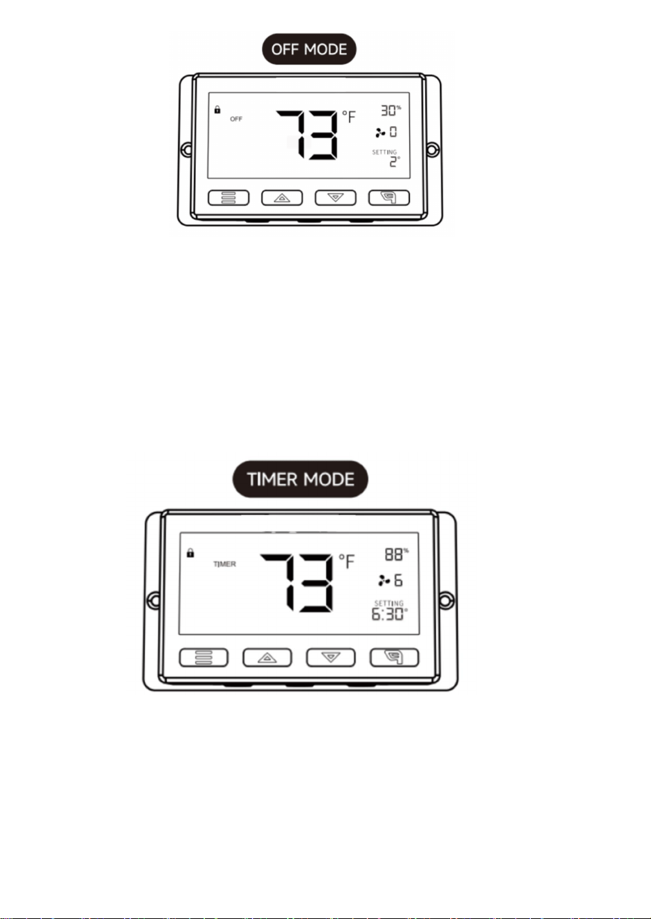
In deze modus draaien de ventilatoren niet, ongeacht de temperatuur
of luchtvochtigheid. Als u in de modus 'Instellingen' op de omhoog-
of omlaagknop drukt, verandert de helderheid van het scherm.
Er zijn vier instellingen voor de helderheid (instelling: 1/2/3/A3). Bij
instelling A3, als het apparaat is Als het scherm 30 seconden
onbeheerd wordt achtergelaten, wordt de helderheid automatisch
weer teruggebracht naar instelling 1.
Als u de knoppen omhoog en omlaag tegelijkertijd ingedrukt houdt,
doorloopt u de temperatuureenheid:
Fahrenheit (°F) en Celsius (°C).
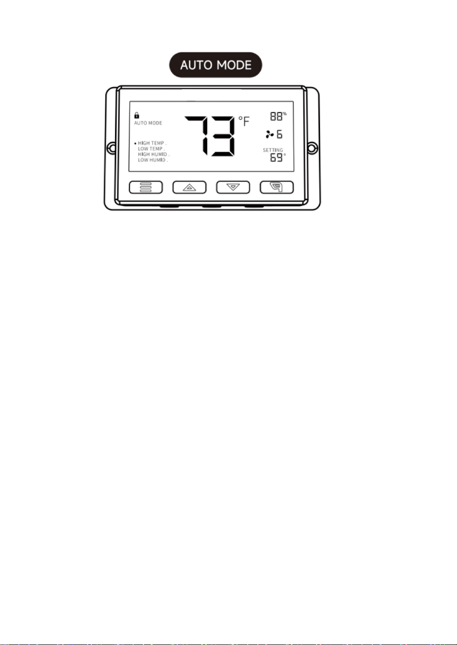
Druk in deze modus op de omhoog- of omlaagknop om een timertijd in te stellen.
De ventilatoren draaien op de snelheid die is ingesteld in de AAN-modus totdat het
aftellen is afgelopen.
Daarna stopt de ventilator met draaien.
De klok begint met aftellen als er gedurende 3 seconden geen knoppen worden
ingedrukt.
11
Als u de timermodus verlaat terwijl het aftellen loopt, wordt de klok gepauzeerd totdat
u terugkeert naar deze modus.
HOGE TEMP:
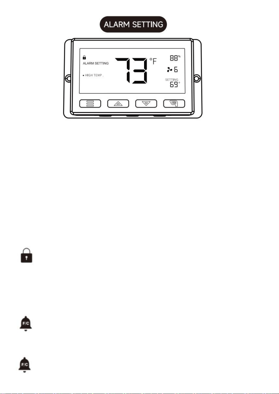
Druk in deze modus op de omhoog- of omlaagknop om een trigger voor hoge
temperaturen in te stellen.
De ventilatoren worden geactiveerd als de gemeten temperatuur van de sonde de
ingestelde temperatuur in deze modus overschrijdt. De geactiveerde ventilatoren
zullen langzaam in snelheid toenemen tot de ingestelde snelheid in de AAN-modus is
bereikt. Wanneer de gemeten temperatuur onder de ingestelde temperatuur zakt,
zullen de ventilatoren langzaam in snelheid afnemen tot ze stoppen. U kunt de
omhoog- en omlaagknop ook tegelijkertijd ingedrukt houden om deze trigger uit te
schakelen. In de instellingen van de houder staat dan UIT voor uit. Houd er rekening
mee dat deze trigger kan worden geactiveerd zolang u zich in de AUTO-modus bevindt,
zelfs als u de andere triggers in de AUTO-modus aan het instellen bent.
LAGE TEMP/HOGE VOCHTIGHEID/LAGE VOCHTIGHEID:
De instelmethode en het bedieningsmechanisme zijn hetzelfde als bij de hierboven
genoemde HOGE TEMP-trigger.
12
HOGE VOCHTIGHEID:
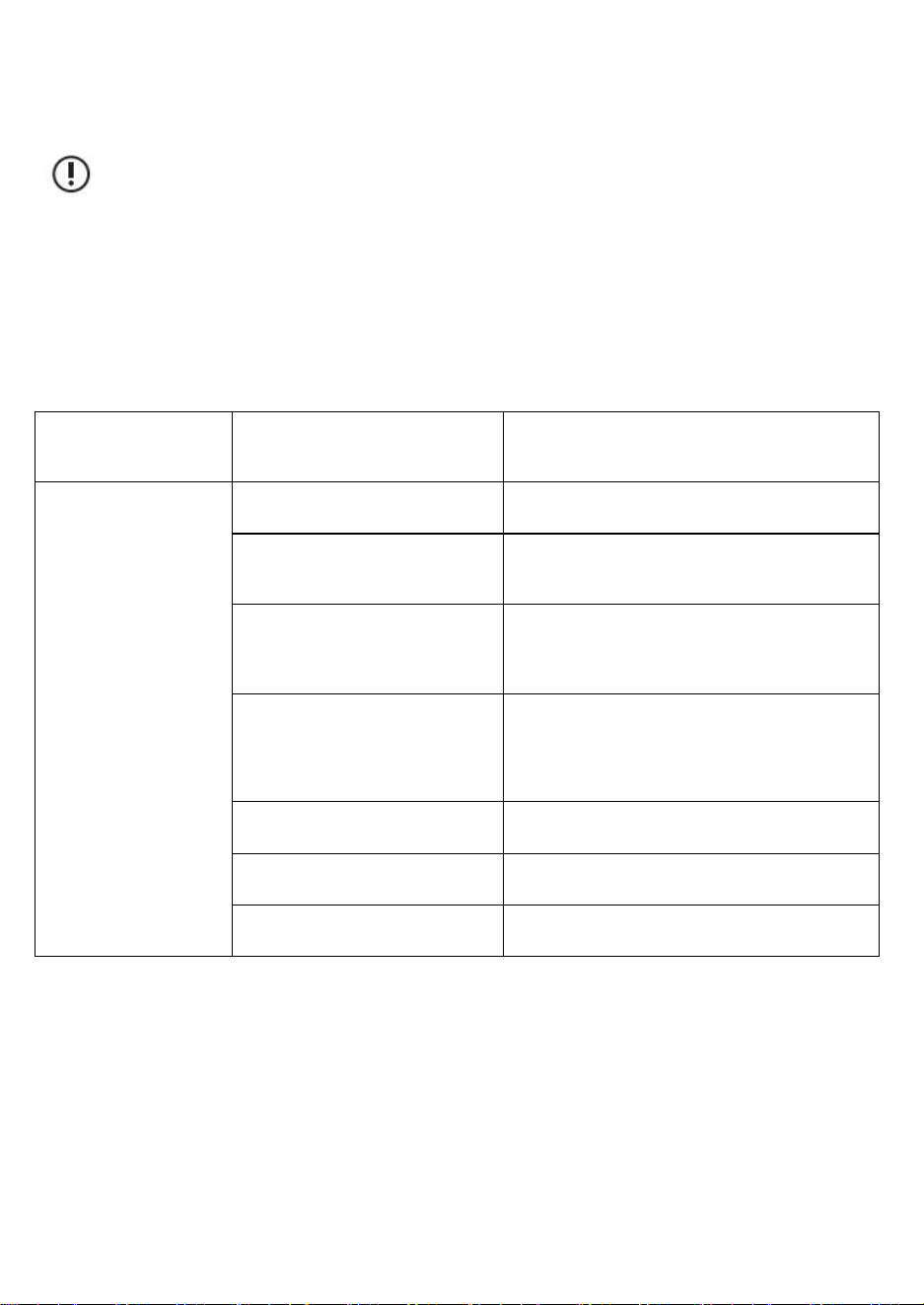
Druk in deze instellingenmodus op de omhoog- en omlaagknop om een alarm voor
hoge vochtigheid in te stellen.
Het alarm wordt geactiveerd als de gemeten vochtigheid van de sonde de ingestelde
vochtigheid in deze modus overschrijdt. Wanneer het alarm afgaat, begint de ventilator
geleidelijk te draaien tot de maximale snelheid, ongeacht uw andere instellingen. U
kunt de omhoog- en omlaagknop ook tegelijkertijd ingedrukt houden om deze
alarminstelling uit te schakelen. De cijfers onder de instellingen geven dan UIT aan. U
moet zich in de modus AUT. AAN of TIMER bevinden om dit alarm te kunnen activeren.
HOGE TEMP/LAGE TEMP/LAGE VOCHTIGHEID:
De instelmethode en het bedieningsmechanisme zijn hetzelfde als bij de hierboven
genoemde HOGE VOCHTIGHEID-trigger.
CONTROLLERVERGRENDELING
Om de controller te vergrendelen en te voorkomen dat instellingen per
ongeluk worden gewijzigd, houdt u de
LEAF-knop drie seconden of langer ingedrukt. Zolang het scherm vergrendeld
is, kunt u
niet van modus wisselen of instellingen wijzigen. Door de LEAF-
knop drie seconden of langer ingedrukt te houden, ontgrendelt u de controller.
TEMPERATUURALARM WAARSCHUWING
Dit pictogram knippert wanneer het door u ingestelde hoge of lage
temperatuuralarm
is geactiveerd.
ALARM VOOR VOCHTIGHEID
Dit pictogram knippert wanneer het alarm voor hoge of lage vochtigheid dat u
13
hebt ingesteld, is
geactiveerd.
voorzichtigheid:
1. Wanneer het apparaat storingen veroorzaakt, controleer dan zelf het
product aan de hand van de onderstaande punten één voor één. Als u
de problemen nog steeds niet kunt vinden, neem dan contact op met de
dealer of laat een professional het product repareren.
2. Probeer de ventilator niet zelf te repareren. Onjuiste bediening en
onderhoud kunnen een elektrische schok of brand veroorzaken.
Omschrijving van
de storing
Analyse
Eliminatiemethoden
De ventilator kan
niet worden gestart
of bediend.
Stroomstoring (zelfcontrole).
Wacht op stroombron.
Het beveiligingsapparaat
schakelt uit (zelftest).
Schakel de stroom opnieuw in.
Controleer of de spanning te
hoog of te laag is (gemeten
door professionals).
Laat het door professionals controleren.
Het ventilatorblad is
geblokkeerd door vreemde
voorwerpen (zelfcontrole).
Schakel de stroom uit en verwijder de
vreemde voorwerpen. Werkzaamheden op
grote hoogte dienen te worden uitgevoerd
door professioneel personeel.
Kortsluiting.
Laat het door professionals controleren.
Motor verbrand.
Laat het door professionals controleren.
Condensator verbrand.
Laat het door professionals controleren.

14
De ventilator
veroorzaakt veel
lawaai en trillingen
als hij draait.
Niet stevig geïnstalleerd
(zelfcontrolerend).
Herinstallatie en
bevestiging.
Het apparaat zelf zit los
(zelfcontrole).
Laat het door een
professional
repareren.
Het blad is bedekt met stof.
Componentdefecten
veroorzaken lastveranderingen
(zelftest).
Laat het door een
professional
repareren.
Het apparaat is geblokkeerd
door vreemde voorwerpen
(zelfcontrole).
Schakel het apparaat
uit en verwijder de
vreemde voorwerpen.
Als de snelheid van het apparaat
toeneemt, controleer dan of de
spanning te hoog is.
Laat het door
professionals
controleren.
Als de snelheid van het apparaat
afneemt, controleer dan of de
spanning te laag is.
Laat het door
professionals
controleren.
Sanven Technologie Ltd.
Adres: Suite 250, 9166 Anaheim Place, Rancho Cucamonga, CA 91730

15

16
LUFTFRÅGA
MODELL: HA-300ME/HA-250ME/HA-350ME/HA-400ME

17
1
MODELL: HA-300ME/HA-250ME/HA-350ME/HA-400ME
Detta är originalinstruktionerna, vänligen läs alla instruktioner noggrant
innan du använder produkten. VEVOR förbehåller sig en tydlig tolkning av
vår användarmanual. Produktens utseende ska vara beroende av den
produkt du mottagit. Vi ber om ursäkt för att vi inte kommer att informera
dig igen om det finns några teknik- eller programuppdateringar för vår
produkt.
Varning – För att minska risken för skador måste användaren
läsa instruktionsmanualen noggrant.
SHUTTER EXHAUST FAN
2
Specifikationer
Modell
Spänning Frekvens
Effekt (W)
HA-300ME
100–240 V ~
50/60 Hz
50
HA-250ME
30
HA-350ME
80
HA-400ME
98
Tillbehörslista
Temperatur- och fuktighetssensorkabel (2,5 m) * 1 , Styrenhet * 1 Ljudkabel (3 m) * 1
Skruvar * 4 , Gummirör * 4
LÄTT ATT MONTERA:
Borra hål i väggen och sätt i bultarna i följande positioner.
Enhet: mm
Montera fläkthuset.
För bultarna genom de
Storlek
En
B
Bultdiameter
HA-250ME
269
174
15x9
HA-300ME
312
190
15x9
HA-350ME
354
235
15x9
HA-400ME
412
220
15 x 9
3
åtta monteringshålen på ytterramen och fäst dem med brickor och
muttrar.
Varsel:
Var försiktig så att bladen inte deformeras under transport och
installation.
Om bladet deformeras störs bladets balans, vilket orsakar ljud och
vibrationer.
PRODUKTSTORLEK
4
Enhet: mm
Storlek
En
B
C
D
E
F
250
314
174
269
170
49
15x9
300
370
190
312
193
56
15x9
350
420
235
354
185
48
15x9
400
480
454
220
221
62
15x9
VARNING
Do not disassemble, repair or modify the fan
motor. Otherwise, there is a risk of fire,
electric shock or injury.
5
VARSEL
Unplug the power plug from the wall outlet
before maintenance, or turn off the circuit
breaker at the switchboard. Otherwise, there
is a risk of electric shock or injury.
Always use at rated voltage. Otherwise,
there is a risk of fire or electric shock.
During operation, do not put fingers or objects
inside the blade. Otherwise, there is a risk of injury.
If the product is not in use for a long time please unplug
the power plug from the socket. Otherwise, there is a risk of
electric shock or fire due to deterioration of insulation.
Wear thick gloves during installation. Cut edges such as
sheet metal, plastic parts, protrusions, or corners of
equipment may cause injury.
Install the fan firmly in a place where is strong enough,
If not it needs to be reinforced. Otherwise, there is a
risk of falling injury.
6
FÖRSLAG
1.Screws can be used to fix
the fan to the wall.
2.If a base is not requested,
just use a tool to unscrew
the screws on the base.
8. Do not install the product in a place
where it may come into direct contact
with water, which may cause malfunction.
4.If the motor shaft is vertical, install the
motor so that it is on the lower side.
Otherwise, it may cause the motor to
malfunction.
7
8
Bruksanvisning
ARTIKEL FÖRKLARING:
1. LÄGESKNAPP①
Genom att trycka på lägesknappen kan du sekventiellt växla mellan följande lägen:
PÅ-LÄGE, AV-LÄGE, AUTOLÄGE, ALARMINSTÄLLNING och TIMER.
Genom att trycka länge på lägesknappen kan du återgå till föregående LÄGE.
2. UPP-KNAPP②/NER-KNAPP③
I vilket läge som helst, tryck på upp-knappen för att öka, tryck på ned-knappen för att
minska.
3. BLADKNAPP④
När styrenheten är igång kan skärmen slås på och av genom att trycka på bladknappen
och styrenheten kan låsas och låsas upp genom att trycka på den i 3 sekunder.
4. GIVARTEMP⑤/FUKTIGHET⑧
Visar aktuell temperatur/fuktighet som detekterats av den trådbundna sensorsonden.
Observera att om givarkabeln inte är korrekt ansluten kommer
temperatur-/fuktighetsvärdet att visa "---".
5. STYRLÄGE⑥
Detta område visar det läge som styrenheten för närvarande är i. Tryck på
lägesknappen för att växla mellan lägena.
6. VARNINGSIKONER⑦
Det här området visar varningar och status från styrenheten, inklusive larm och
skärmlås.
7. FLÄKTHASTIGHET⑨
Visar fläktens aktuella hastighet.
8.INSTÄLLNING⑩
Visar värdet du har ställt in för det aktuella läget. Tryck på upp- eller nedknappen för att
9
ändra.
Förklaring av läge/inställning
Tryck på lägesknappen för att växla mellan regulatorns tillgängliga
programmering. lägen och inställningar: PÅ/AV-läge, TIMER-läge,
AUTO-läge (4 utlösare),
LARMinställningar (4 utlösare).
I det här läget körs fläktarna kontinuerligt oavsett temperatur eller
luftfuktighet. Och hastigheten som ställs in i det här läget är den
maximala hastigheten som fläktarna kan uppnå.
AUTO-läge.
10
I det här läget går inte fläktarna oavsett temperatur eller luftfuktighet.
I det här läget I läget ändras skärmens ljusstyrka genom att trycka på
upp- eller nedknappen.
Det finns fyra inställningar för ljusstyrka (inställning: 1/2/3/A3). Om
enheten är inställd på A3, Om den lämnas obevakad i 30 sekunder,
kommer skärmen automatiskt att dämpa ljusstyrkan igen till
inställning 1.
Genom att hålla nere upp- och ned-knappen samtidigt växlar du
mellan temperaturenheterna:
Fahrenheit (°F) och Celsius (°C).
I det här läget trycker du på upp- eller nedknappen för att ställa in en tid för timern.
Fläktarna kommer att gå med den hastighet som ställts in i ON-läget tills nedräkningen
är slut.
Därefter slutar fläkten att gå.
Klockan börjar räkna ner om inga knappar trycks ner på 3 sekunder.
Om du lämnar timerläget medan nedräkningen pågår pausar klockan tills du återgår till
det här läget.
11
HÖG TEMP:
I det här läget trycker du på upp- eller ned-knappen för att ställa in en
högtemperaturutlösare.
Fläktarna aktiveras om sondens uppmätta temperatur överstiger den temperatur du
har ställt in i det här läget. De aktiverade fläktarna ökar långsamt i hastighet tills de når
den hastighet som ställts in i PÅ-läge. När den uppmätta temperaturen sjunker under
din inställda temperatur minskar fläktarna långsamt i hastighet tills de stannar. Du kan
också hålla ner upp- och ned-knappen samtidigt för att stänga av den här utlösaren, då
hållerinställningarna visar AV för av. Observera att den här utlösaren kan aktiveras så
länge du är i AUTO-läge, även om du konfigurerar de andra AUTO-lägesutlösarna.
LÅG TEMP/HÖG FUKTIGHETSNIVÅ/LÅG FUKTIGHETSNIVÅ:
Inställningsmetoden och funktionsmekanismen är densamma som för HÖG
TEMP-utlösaren som nämns ovan.
12
HÖG FUKT:
I detta inställningsläge trycker du på upp- och ned-knappen för att ställa in ett larm för
hög luftfuktighet.
Larmet aktiveras om sondens uppmätta luftfuktighet överstiger den luftfuktighet du
har ställt in i detta läge. När larmet utlöses börjar fläkten gradvis snurra till maximal
hastighet oavsett dina andra inställningar. Du kan också hålla ner upp- och
ned-knappen samtidigt för att stänga av larminställningen, där siffrorna under
inställningarna visar AV. Du måste vara i AUT. PÅ- eller TIMER-läge för att larmet ska
kunna aktiveras.
HÖG TEMP/LÅG TEMP/LÅG FUKTIGHETSINSTÄLLNING:
Inställningsmetoden och funktionsmekanismen är densamma som för HÖG
FUKTIGHETSINSTÄLLNING som nämns ovan.
KONTROLLLÅS
För att låsa kontrollen för att förhindra att inställningar ändras av misstag, håll
ner
LEAF-knappen i tre sekunder eller mer. Medan displayen är låst
kan du inte växla lägen eller ändra några inställningar. Om du håller ner LEAF
-knappen i tre sekunder eller mer låses kontrollen upp.
TEMPERATURLARM
Den här ikonen blinkar när det höga eller låga temperaturlarm som du har
ställt in
har utlösts.
LARM FÖR LUFTFUKTIGHET
Den här ikonen blinkar när det inställda larmet för hög eller låg luftfuktighet har
utlösts.
försiktighet:
1. Om utrustningen orsakar funktionsfel, vänligen kontrollera den själv
enligt nedanstående punkter en i taget. Om du fortfarande inte kan hitta
problemen, vänligen kontakta återförsäljaren eller låt en professionell
reparera produkten.
2. Reparera inte fläkten själv. Felaktig användning och underhåll orsakar
elektriska stötar eller brand.
Beskrivning av
fel
Analys
Elimineringsmetoder
13
Beskrivning av
fel
Analys
Elimineringsmetoder
Fläkten kan inte
startas eller
användas.
Strömavbrott (självkontroll).
Väntar på strömkälla.
Kretsskyddet löser ut
(självkontroll).
Starta om strömmen.
Kontrollera om spänningen är för
hög eller för låg (mätt av fackmän).
Kontrollera av proffs.
Fläktbladet är blockerat av
främmande föremål (självkontroll).
Stäng av strömmen och ta bort
främmande föremål. Höghöjdsarbete bör
utföras av professionell personal.
Kortslutning.
Kontrollera av proffs.
Motorbrännskada.
Kontrollera av proffs.
Kondensatorbrännskada.
Kontrollera av proffs.

14
Fläkten orsakar
mycket ljud och
vibrationer när den är
igång.
Inte ordentligt installerad
(självkontroll).
Återinstallation och
fastsättning.
Själva enheten är lös
(självkontroll).
Låt proffset fixa.
Bladet är täckt av damm.
Komponentfel orsakar att
belastningen ändras
(självkontroll).
Låt proffset fixa.
Enheten är blockerad av
främmande föremål
(självkontroll).
Stäng av strömmen och
ta ut de främmande
föremålen.
Om enhetens hastighet ökar,
kontrollera om spänningen är
för hög.
Kontrollera av proffs.
Om enhetens hastighet blir
låg, kontrollera om
spänningen är för låg.
Kontrollera av proffs.
Sanven Technology Ltd.
Adress: Suite 250, 9166 Anaheim Place, Rancho Cucamonga, CA 91730

15

16
VENTILADOR DE ESCAPE CON
OBTURADOR
MODELO: HA-300ME/HA-250ME/HA-350ME/HA-400ME

17
1
MODELO:HA-300ME/HA-250ME/HA-350ME/HA-400ME
Estas son las instrucciones originales; lea atentamente todas las
instrucciones del manual antes de utilizarlo. VEVOR se reserva el
derecho de interpretar su manual de usuario. La apariencia del producto
dependerá del producto que haya recibido. Le rogamos que nos disculpe
si no le informamos de nuevo si hay actualizaciones tecnológicas o de
software en nuestro producto.
Advertencia: Para reducir el riesgo de lesiones, el usuario
debe leer atentamente el manual de instrucciones.
SHUTTER EXHAUST FAN
2
Presupuesto
Modelo
Frecuencia de
voltaje
Potencia (W)
HA-300ME
100-240 V~
50/60 Hz
50
HA-250ME
30
HA-350ME
80
HA-400ME
98
Lista de accesorios
Cable sensor de temperatura y humedad (2,5 m) * 1 , Controlador * 1, Cable de audio (3
m) * 1,
Tornillos * 4 , Ojales de goma * 4
FÁCIL DE MONTAR:
Taladre agujeros en la pared e inserte los pernos en las siguientes
posiciones.
Unidad: mm
Tamaño
A
B
Diámetro del perno
HA-250ME
269
174
15x9
HA-300ME
312
190
15x9
3
Instale el cuerpo del ventilador.
Pase los pernos a través de los ocho orificios de montaje en el marco
exterior y asegúrelos con arandelas y tuercas.
Aviso:
Tenga cuidado de no deformar las cuchillas durante el transporte y la
instalación.
Si la cuchilla se deforma, se altera su equilibrio, lo que provoca ruido
HA-350ME
354
235
15x9
HA-400ME
412
220
15 x 9
4
y vibración.
TAMAÑO DEL PRODUCTO
Unidad: mm
Tamaño
A
B
do
D
mi
F
250
314
174
269
170
49
15x9
300
370
190
312
193
56
15x9
350
420
235
354
185
48
15x9
400
480
454
220
221
62
15x9
ADVERTENCIA
5
AVISO
Do not disassemble, repair or modify the fan
motor. Otherwise, there is a risk of fire,
electric shock or injury.
Unplug the power plug from the wall outlet
before maintenance, or turn off the circuit
breaker at the switchboard. Otherwise, there
is a risk of electric shock or injury.
Always use at rated voltage. Otherwise,
there is a risk of fire or electric shock.
During operation, do not put fingers or objects
inside the blade. Otherwise, there is a risk of injury.
If the product is not in use for a long time please unplug
the power plug from the socket. Otherwise, there is a risk of
electric shock or fire due to deterioration of insulation.
Wear thick gloves during installation. Cut edges such as
sheet metal, plastic parts, protrusions, or corners of
equipment may cause injury.
6
SUGERENCIAS
1.Screws can be used to fix
the fan to the wall.
2.If a base is not requested,
just use a tool to unscrew
the screws on the base.
9. Do not install the product in a place
where it may come into direct contact
with water, which may cause malfunction.
4.If the motor shaft is vertical, install the
motor so that it is on the lower side.
Otherwise, it may cause the motor to
malfunction.
7
8
Instrucciones de funcionamiento
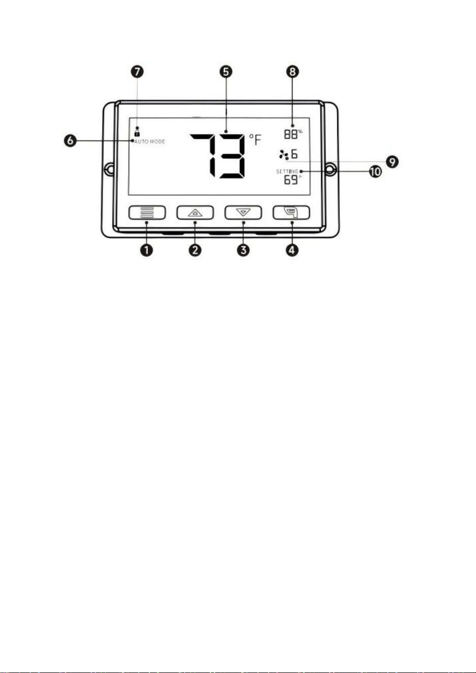
EXPLICACIÓN DEL ELEMENTO:
1. BOTÓN DE MODO ①
Al presionar el botón de modo, puede alternar entre los siguientes modos:
MODO ENCENDIDO, MODO APAGADO, MODO AUTOMÁTICO, AJUSTE DE ALARMA y
TEMPORIZADOR.
Al mantener presionado el botón de modo, puede regresar al MODO anterior.
2. BOTÓN ARRIBA ②/BOTÓN ABAJO ③
En cualquier modo, presione el botón arriba para aumentar o el botón abajo para
disminuir.
3. BOTÓN HOJA ④
Cuando el controlador está funcionando, la pantalla se puede encender y apagar
presionando el botón hoja, y el controlador se puede bloquear y desbloquear
presionándolo durante 3 segundos.
4. TEMPERATURA/HUMEDAD DE LA SONDA ⑤/HUMEDAD ⑧
Muestra la temperatura/humedad actual detectada por la sonda del sensor con cable.
Tenga en cuenta que si el cable sensor no está conectado correctamente, el valor de
temperatura/humedad mostrará "---".
5. MODO DEL CONTROLADOR⑥
Esta área muestra el modo en el que se encuentra el controlador. Pulse el botón de
modo para recorrer los modos.
6. ICONOS DE ALERTA⑦
Esta área muestra las alertas y estados del controlador, incluyendo alarmas y bloqueo
de pantalla.
7. VELOCIDAD DEL VENTILADOR⑨
Muestra la velocidad actual del ventilador.
9
8. AJUSTE⑩
Muestra el valor configurado para el modo actual. Pulse los botones arriba o abajo para
cambiar.
Explicación del modo/configuración
Presione el botón Mode para recorrer la programación disponible del
controlador. Modos y configuraciones: Modo ON/OFF, Modo
TEMPORIZADOR, Modo AUTOMÁTICO (4 disparadores),
Configuración de ALARMA (4 disparadores).
En este modo, los ventiladores funcionarán continuamente
independientemente de la temperatura o la humedad. Y la velocidad
establecida en este modo será la velocidad máxima que los
ventiladores pueden alcanzar en
Modo AUTO.
10
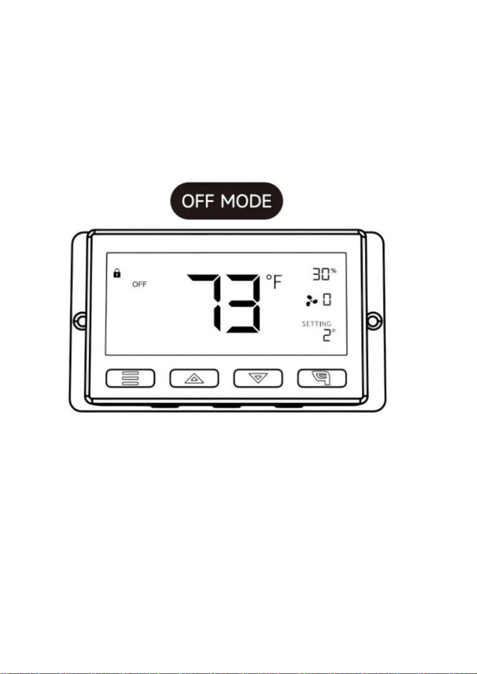
En este modo, los ventiladores no funcionarán independientemente
de la temperatura o la humedad. Mientras esté en este modo Modo, al
presionar el botón arriba o abajo se cambiará el brillo de la pantalla.
Hay cuatro configuraciones de brillo (Configuración: 1/2/3/A3). En la
configuración A3, si el dispositivo está... Si se deja desatendida
durante 30 segundos, la pantalla atenuará automáticamente su brillo.
al ajuste 1.
Manteniendo presionados los botones arriba y abajo al mismo tiempo
se desplazará por las unidades de temperatura:
Fahrenheit (°F) y Celsius (°C).
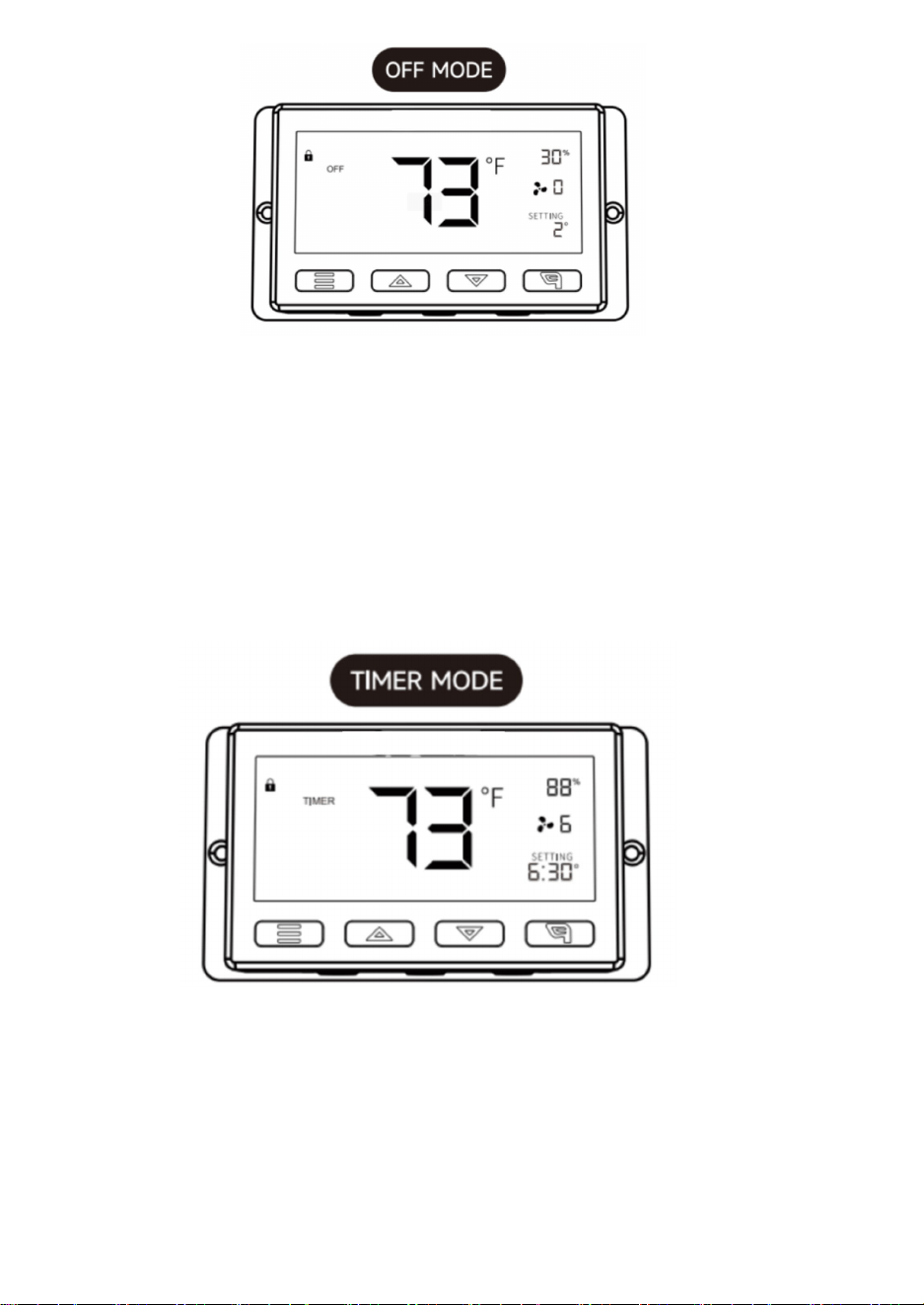
En este modo, presione el botón arriba o abajo para configurar el temporizador.
Los ventiladores funcionarán a la velocidad establecida en el modo ENCENDIDO hasta
que finalice la cuenta regresiva.
Después, se detendrán.
El reloj comenzará la cuenta regresiva si no se presiona ningún botón durante 3
segundos.
11
Salir del modo temporizador mientras la cuenta regresiva está en marcha pausará el
reloj hasta que regrese a este modo.
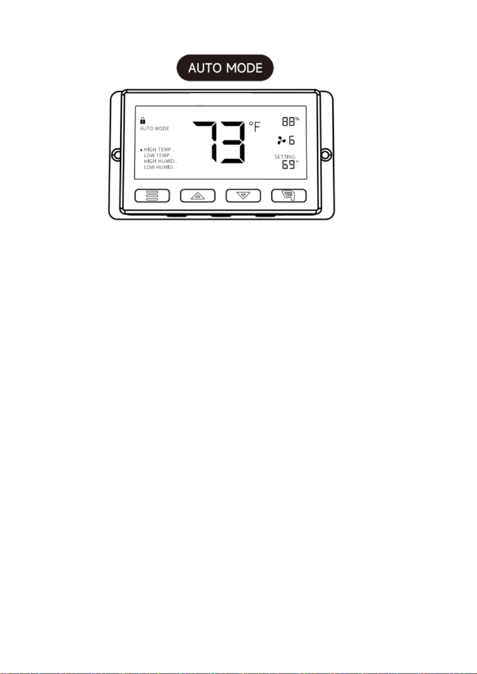
ALTA TEMPERATURA:
En este modo, presione el botón arriba o abajo para configurar un disparador de alta
temperatura.
Los ventiladores se activarán si la temperatura medida por la sonda supera la
temperatura configurada en este modo. Los ventiladores activados aumentarán
lentamente su velocidad hasta alcanzar la velocidad configurada en el modo
ENCENDIDO. Si la temperatura medida desciende por debajo de la temperatura
configurada, los ventiladores disminuirán lentamente su velocidad hasta detenerse.
También puede mantener presionados los botones arriba y abajo simultáneamente
para desactivar este disparador; en este caso, la configuración del soporte mostrará
"APAGADO". Tenga en cuenta que este disparador puede funcionar mientras esté en
modo AUTOMÁTICO, incluso si está configurando los demás disparadores del modo
AUTOMÁTICO.
BAJA TEMPERATURA/ALTA HUMEDAD/BAJA HUMEDAD:
El método de configuración y el mecanismo de funcionamiento son los mismos que los
del disparador de ALTA TEMPERATURA mencionado anteriormente.
12
HUMEDAD ALTA:
En este modo de configuración, presione los botones arriba y abajo para configurar
una alarma de humedad alta.
La alarma se activará si la humedad medida por la sonda supera la configurada en este
modo. Cuando se activa la alarma, el ventilador comenzará a girar gradualmente a la
velocidad máxima, independientemente de la configuración. También puede mantener
presionados los botones arriba y abajo simultáneamente para desactivar esta alarma;
en este caso, los dígitos debajo de la configuración mostrarán "OFF". Para que la
alarma se active, deberá estar en modo AUT. ON o TIMER.
ALTA TEMPERATURA/BAJA TEMPERATURA/BAJA HUMEDAD:
El método de configuración y el mecanismo de funcionamiento son los mismos que los
del disparador ALTA HUMEDAD mencionado anteriormente.
BLOQUEO DEL MANDO
Para bloquear el mando y evitar cambios accidentales en la configuración,
mantenga pulsado el
botón LEAF durante tres segundos o más. Mientras la pantalla esté bloqueada,
no podrá cambiar de modo ni modificar ninguna configuración. Mantener
pulsado el
botón LEAF durante tres segundos o más desbloqueará el mando.
ALERTA DE ALARMA DE TEMPERATURA
Este icono parpadeará cuando
se active la alarma de temperatura alta o baja que haya configurado.
ALERTA DE ALARMA DE HUMEDAD
Este icono parpadeará cuando
se haya activado la alarma de humedad alta o baja que haya configurado.
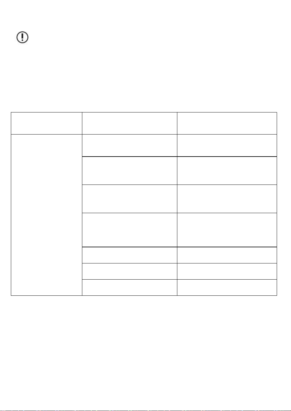
13
precaución:
1. Cuando el equipo presente fallas, verifique usted mismo de acuerdo
con los elementos siguientes uno por uno. Si aún no puede encontrar los
problemas, comuníquese con el distribuidor o deje que un profesional
repare el producto.
2. No repare el ventilador usted mismo. El uso y mantenimiento
inadecuados provocarán descargas eléctricas o incendios.
Descripción del mal
funcionamiento
Análisis
Métodos de eliminación
El ventilador no se
puede poner en marcha
ni operar.
Corte de energía
(autocomprobación).
Esperando fuente de energía.
El dispositivo de protección del
circuito se dispara (se
autocomprueba).
Reinicie la energía.
Compruebe si el voltaje es
demasiado alto o demasiado bajo
(medido por profesionales).
Revisado por profesionales.
La paleta del ventilador está
bloqueada por objetos extraños
(autocomprobación).
Apague el equipo y retire los objetos
extraños. Las operaciones a gran
altitud deben ser realizadas por
personal profesional.
Cortocircuito.
Revisado por profesionales.
Quemadura del motor.
Revisado por profesionales.
Quemadura del condensador.
Revisado por profesionales.

14
El ventilador provoca
mucho ruido y
vibración cuando está
funcionando.
No instalado firmemente
(autocomprobación).
Reinstalación y
fijación.
El dispositivo en sí está suelto
(autocomprobación).
Deje que el
profesional lo
arregle.
La cuchilla está cubierta de polvo.
Los defectos en los componentes
provocan cambios en la carga
(autocomprobación).
Deje que el
profesional lo
arregle.
El dispositivo está bloqueado por
objetos extraños
(autocomprobación).
Apague y retire
los objetos
extraños.
Si la velocidad del dispositivo
aumenta, verifique si el voltaje es
demasiado alto.
Revisado por
profesionales.
Si la velocidad del dispositivo
disminuye, verifique si el voltaje es
demasiado bajo.
Revisado por
profesionales.
Sanven Tecnología Ltd.
Dirección: Suite 250, 9166 Anaheim Place, Rancho Cucamonga, CA
91730

15

16

17
VENTILATORE DI SCARICO A SERRANDE
MODELLO: HA-300ME/HA-250ME/HA-350ME/HA-400ME

18
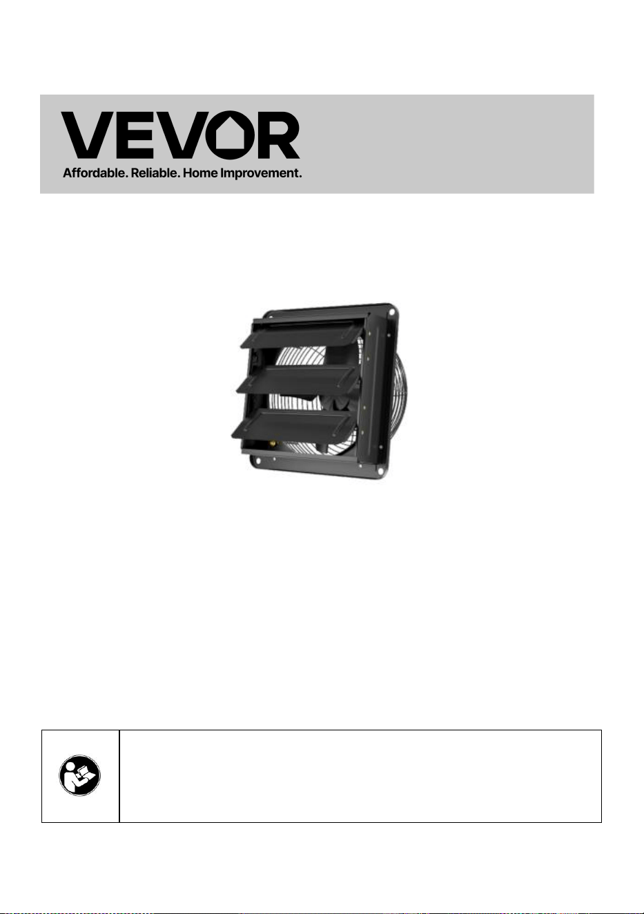
1
MODELLO:HA-300ME/HA-250ME/HA-350ME/HA-400ME
Queste sono le istruzioni originali, si prega di leggere attentamente tutte
le istruzioni del manuale prima dell'uso. VEVOR si riserva la piena
interpretazione del proprio manuale utente. L'aspetto del prodotto
dipenderà dal prodotto ricevuto. Vi preghiamo di scusarci se non vi
informeremo più in caso di aggiornamenti tecnologici o software sul
nostro prodotto.
Avvertenza: per ridurre il rischio di lesioni, l'utente deve
leggere attentamente il manuale di istruzioni.
SHUTTER EXHAUST FAN
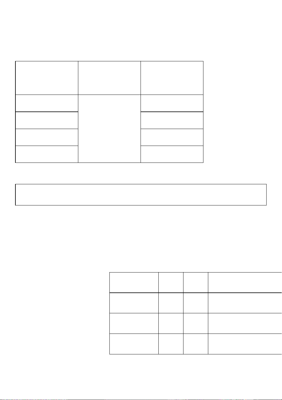
2
Specifiche
Modello
Frequenza di
tensione
Potenza (W)
HA-300ME
100-240 V~
50/60 Hz
50
HA-250ME
30
HA-350ME
80
HA-400ME
98
Elenco degli accessori
Cavo sensore di temperatura e umidità (2,5 m) *1 , Controller *1, Cavo audio (3 m) *1,
Viti *4 , Passacavi in gomma *4
FACILE DA MONTARE:
Praticare dei fori nel muro e inserire i bulloni nelle seguenti posizioni.
Unità: mm
Misurare
UN
B
Diametro del bullone
HA-250ME
269
174
15x9
HA-300ME
312
190
15x9
HA-350ME
354
235
15x9
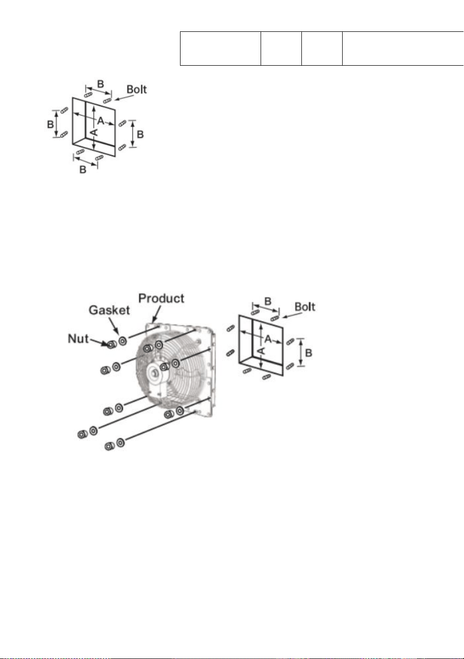
3
Installare il corpo della ventola.
Far passare i bulloni attraverso gli otto fori di montaggio sul telaio
esterno e fissarli con rondelle e dadi.
Avviso:
Fare attenzione a non deformare le lame durante il trasporto e
l'installazione.
Se la lama è deformata, l'equilibrio della lama viene compromesso,
HA-400ME
412
220
15 x 9
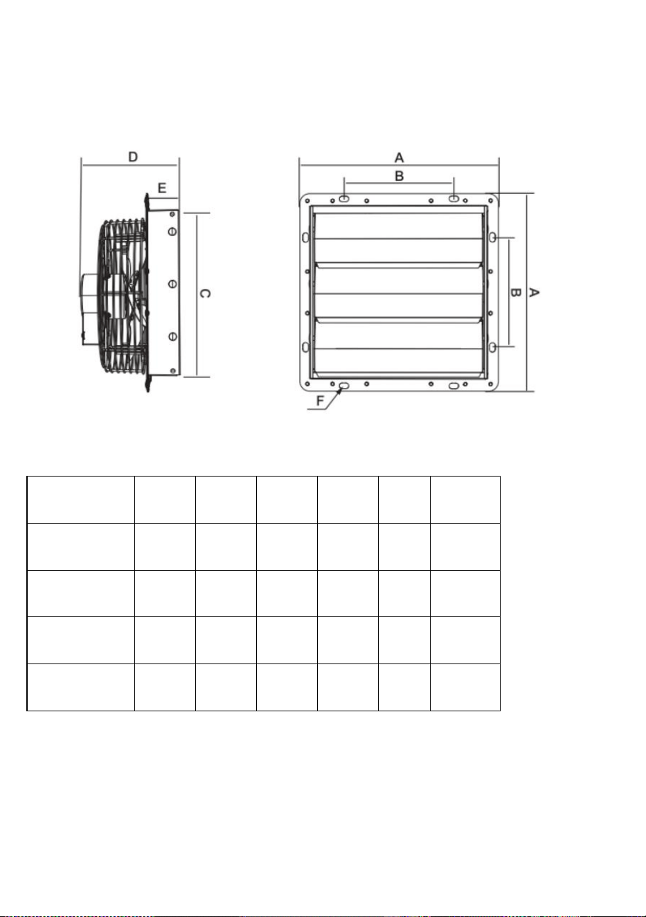
4
causando rumore e vibrazioni.
DIMENSIONE DEL PRODOTTO
Unità: mm
Misurare
UN
B
C
D
E
F
250
314
174
269
170
49
15x9
300
370
190
312
193
56
15x9
350
420
235
354
185
48
15x9
400
480
454
220
221
62
15x9
AVVERTIMENTO
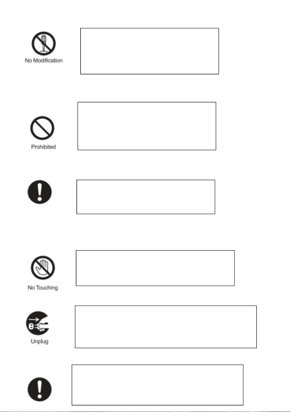
5
AVVISO
Do not disassemble, repair or modify the fan
motor. Otherwise, there is a risk of fire,
electric shock or injury.
Unplug the power plug from the wall outlet
before maintenance, or turn off the circuit
breaker at the switchboard. Otherwise, there
is a risk of electric shock or injury.
Always use at rated voltage. Otherwise,
there is a risk of fire or electric shock.
During operation, do not put fingers or objects
inside the blade. Otherwise, there is a risk of injury.
If the product is not in use for a long time please unplug
the power plug from the socket. Otherwise, there is a risk of
electric shock or fire due to deterioration of insulation.
Wear thick gloves during installation. Cut edges such as
sheet metal, plastic parts, protrusions, or corners of
equipment may cause injury.
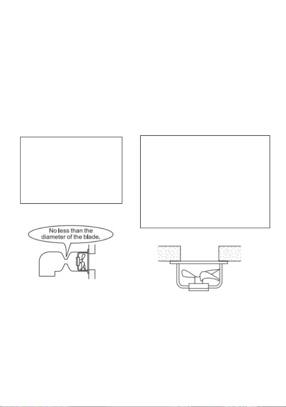
6
SUGGERIMENTI
1.Screws can be used to fix
the fan to the wall.
2.If a base is not requested,
just use a tool to unscrew
the screws on the base.
10. Do not install the product in a place
where it may come into direct contact
with water, which may cause malfunction.
4.If the motor shaft is vertical, install the
motor so that it is on the lower side.
Otherwise, it may cause the motor to
malfunction.
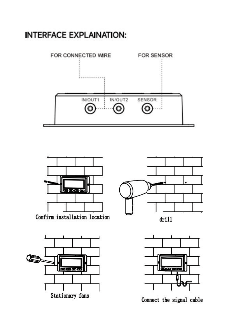
7
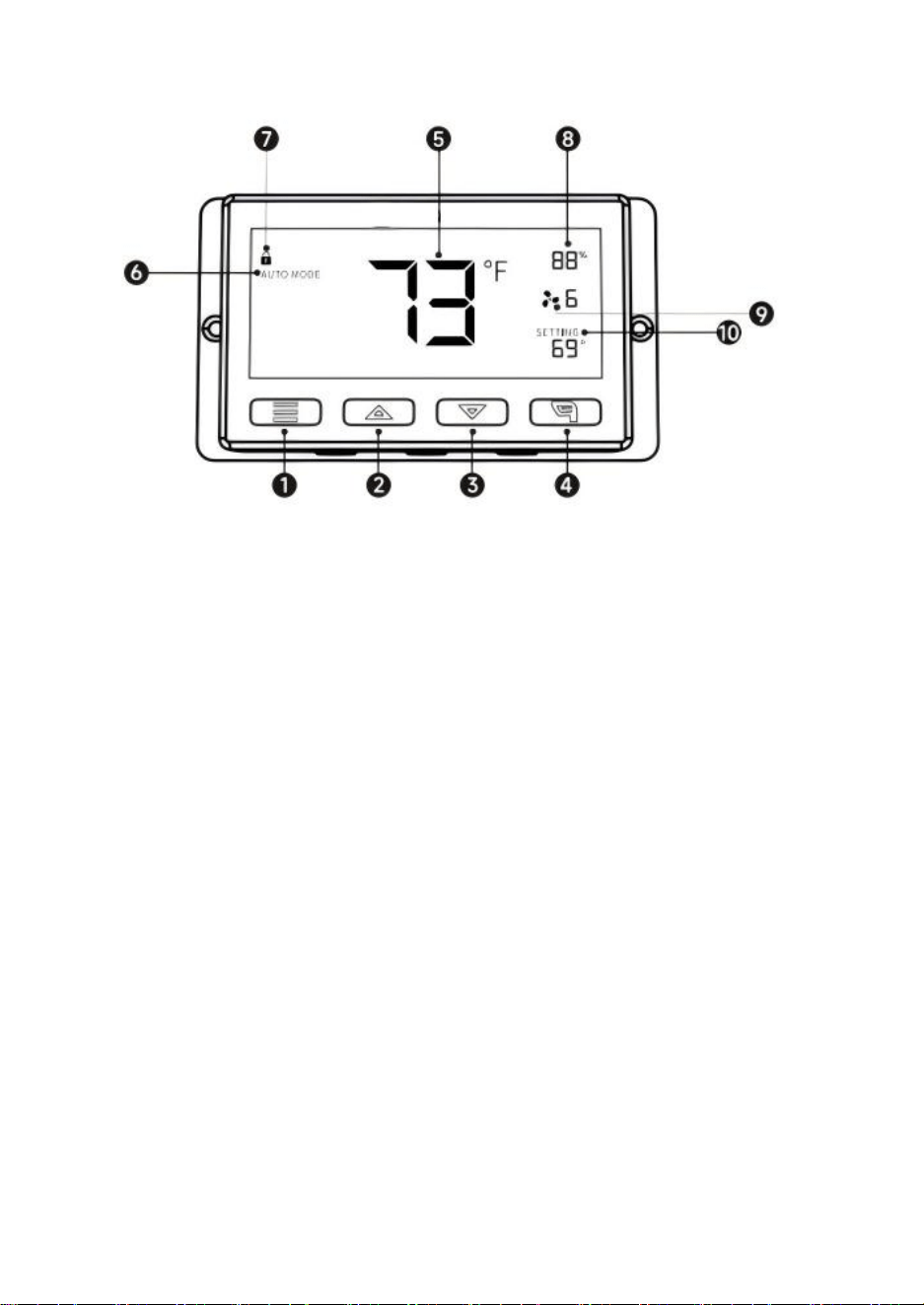
8
Istruzioni per l'uso
SPIEGAZIONE DELL'ELEMENTO:
1. PULSANTE MODALITÀ①
Premendo il pulsante modalità è possibile scorrere in sequenza le seguenti modalità:
MODALITÀ ON, MODALITÀ OFF, MODALITÀ AUTO, IMPOSTAZIONE SVEGLIA e TIMER.
Premendo a lungo il pulsante modalità è possibile tornare alla MODALITÀ precedente.
2. PULSANTE SU②/PULSANTE GIÙ③
In qualsiasi modalità, premere il pulsante su per aumentare, premere il pulsante giù per
diminuire.
3. PULSANTE FOGLIA④
Quando il controller è in funzione, lo schermo può essere acceso e spento premendo il
pulsante foglia e il controller può essere bloccato e sbloccato premendolo per 3
secondi.
4. SONDA TEMPERATURA⑤/UMIDITÀ⑧
Visualizza la temperatura/umidità attuale rilevata dalla sonda del sensore cablata.
Si prega di notare che se il cavo di rilevamento non è collegato correttamente, il valore
di temperatura/umidità mostrerà "---".
5. MODALITÀ CONTROLLER⑥
Quest'area visualizza la modalità in cui si trova attualmente il controller. Premere il
pulsante Modalità per scorrere le modalità.
6. ICONE DI AVVISO⑦
Quest'area visualizza gli avvisi e gli stati del controller, inclusi allarmi e blocco schermo.
7. VELOCITÀ VENTOLA⑨
Visualizza la velocità attuale della ventola.
8. IMPOSTAZIONE⑩
Visualizza il valore impostato per la modalità corrente. Premere il pulsante su o giù per
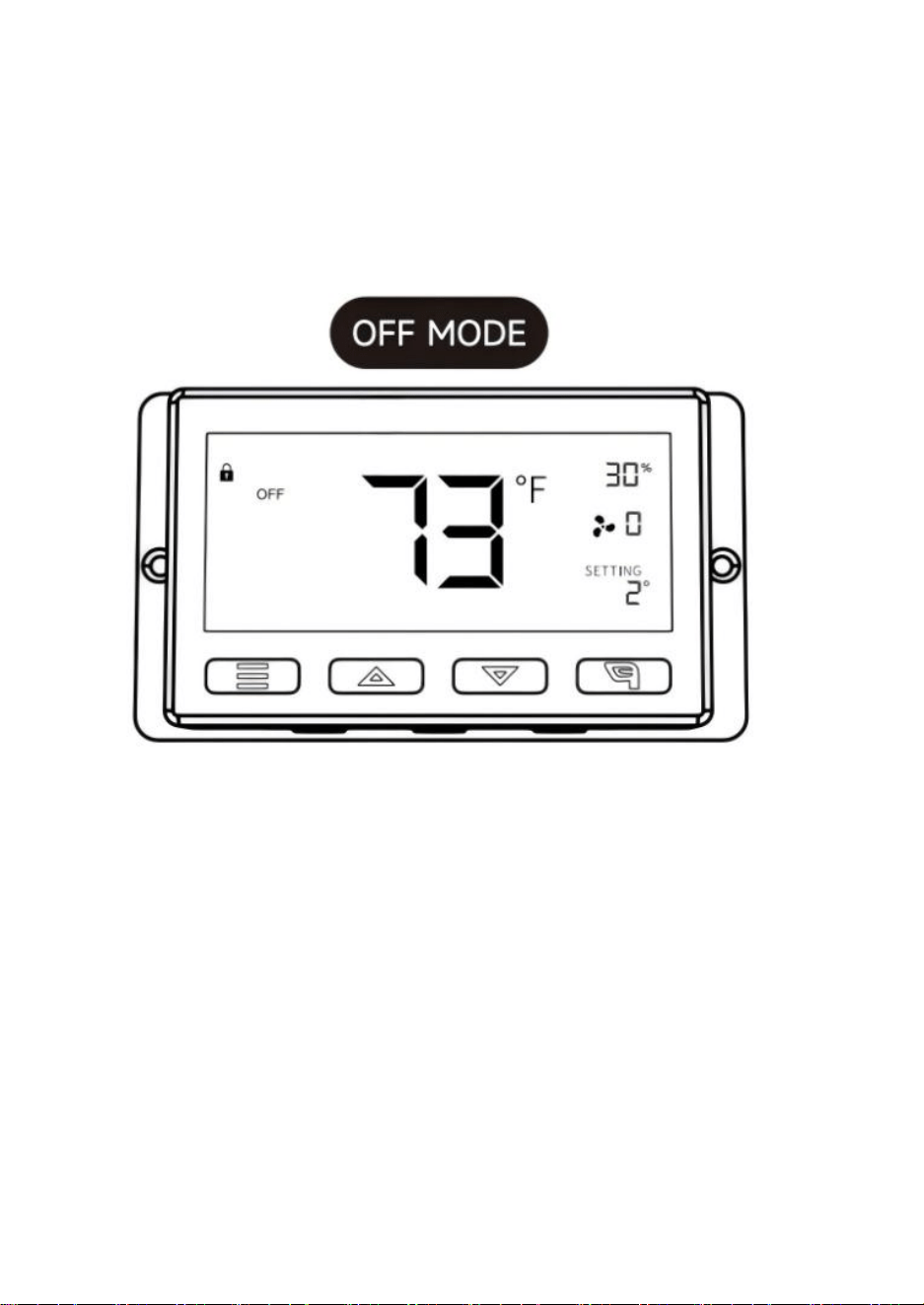
9
modificarlo.
Spiegazione della modalità/impostazione
Premere il pulsante Modalità per scorrere la programmazione
disponibile del controller modalità e impostazioni: modalità ON/OFF,
modalità TIMER, modalità AUTO (4 trigger),
Impostazioni ALLARME (4 trigger).
In questa modalità, le ventole funzioneranno continuamente
indipendentemente dalla temperatura o dall'umidità. E la velocità
impostata in questa modalità sarà la velocità massima che le ventole
possono raggiungere in
Modalità AUTO.
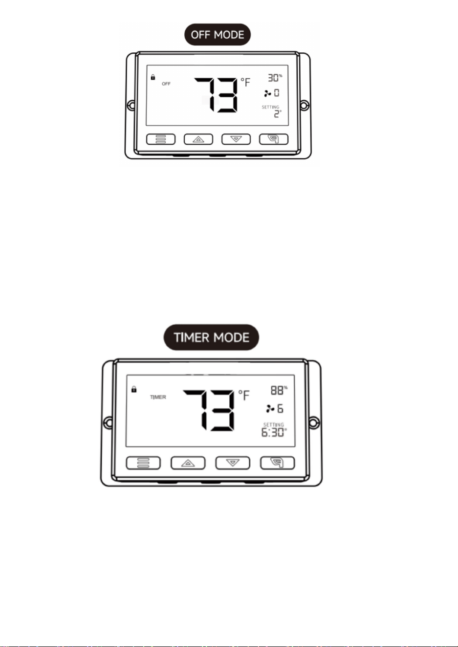
10
In questa modalità, le ventole non funzioneranno indipendentemente
dalla temperatura o dall'umidità. Mentre è in questa modalità modalità,
premendo il pulsante su o giù si modifica la luminosità del display.
Sono disponibili quattro impostazioni per la luminosità (impostazione:
1/2/3/A3). Nell'impostazione A3, se il dispositivo è lasciato incustodito
per 30 secondi, il display ridurrà automaticamente la sua luminosità
all'impostazione 1.
Tenendo premuti contemporaneamente i pulsanti su e giù è possibile
scorrere le unità di temperatura:
Fahrenheit (°F) e Celsius (°C).
In questa modalità, premere il pulsante su o giù per impostare un orario per il timer.
Le ventole funzioneranno alla velocità impostata in modalità ON fino al termine del
conto alla rovescia.
Successivamente, la ventola si fermerà.
L'orologio inizierà il conto alla rovescia se non si preme alcun pulsante per 3 secondi.
Uscendo dalla modalità timer mentre il conto alla rovescia è in corso, l'orologio verrà
messo in pausa fino al ritorno a questa modalità.
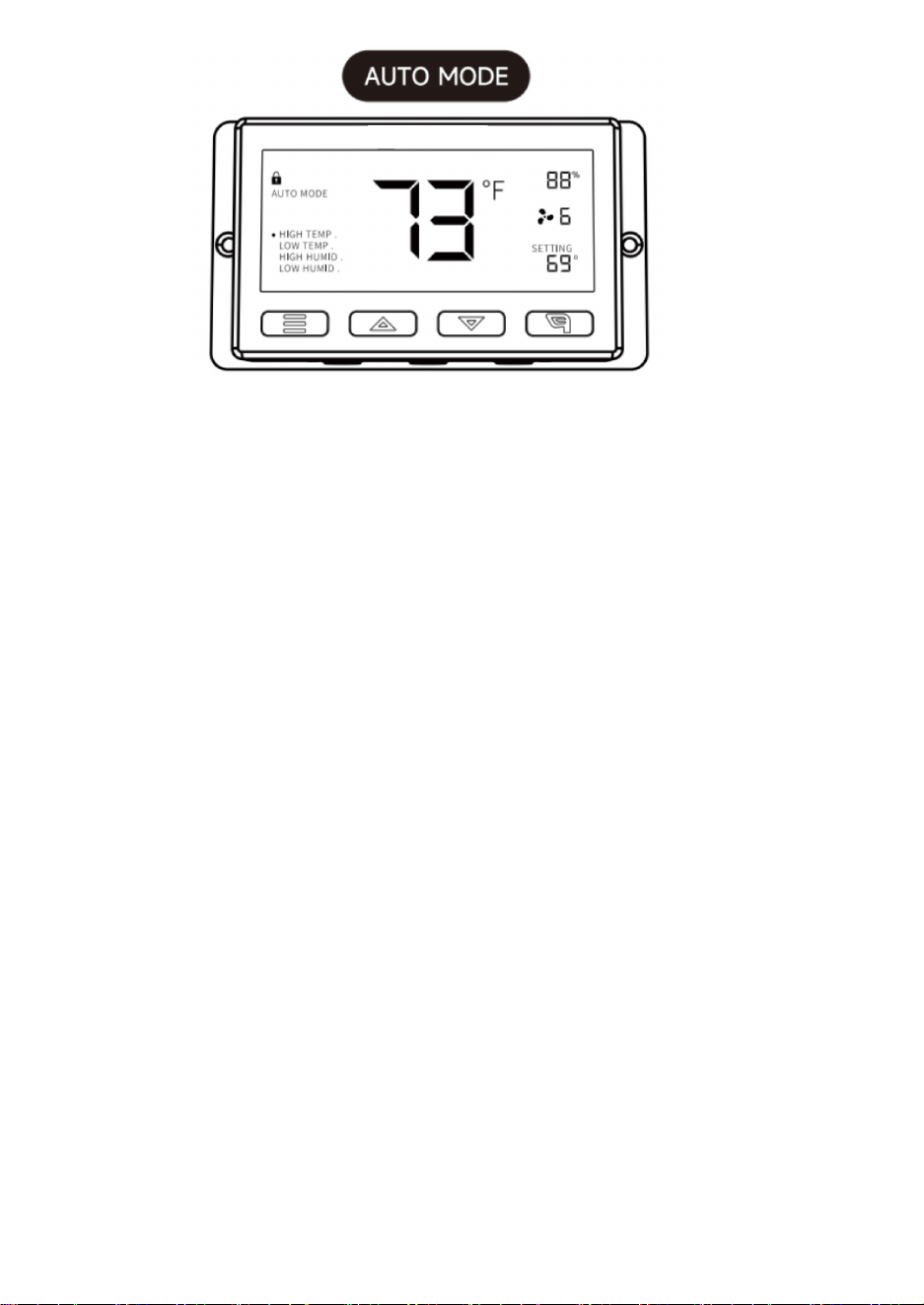
11
TEMPERATURA ALTA:
In questa modalità, premere il pulsante su o giù per impostare un trigger per
temperatura elevata.
Le ventole si attiveranno se la temperatura misurata dalla sonda supera la temperatura
impostata in questa modalità. Le ventole attivate aumenteranno lentamente la velocità
fino a raggiungere la velocità impostata in modalità ON. Ogni volta che la temperatura
misurata scende al di sotto della temperatura impostata, le ventole diminuiranno
lentamente la velocità fino a fermarsi. È anche possibile tenere premuti
contemporaneamente i pulsanti su e giù per disattivare questo trigger, in questo caso
le impostazioni del supporto mostreranno OFF per spento. Si noti che questo trigger
può attivarsi finché si è in modalità AUTO, anche se si stanno configurando gli altri
trigger della modalità AUTO.
BASSA TEMPERATURA/ALTA UMIDITÀ/BASSA UMIDITÀ:
il metodo di impostazione e il meccanismo di funzionamento sono gli stessi del trigger
ALTA TEMPERATURA menzionato sopra.
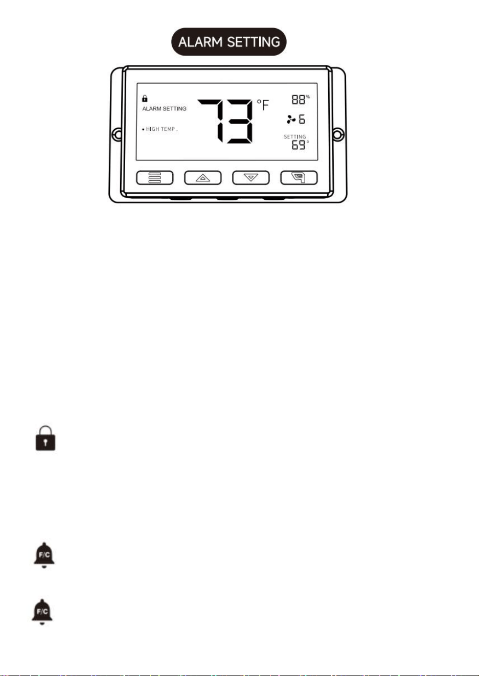
12
UMIDITÀ ELEVATA:
In questa modalità di impostazione, premere i pulsanti su e giù per impostare un
allarme di umidità elevata.
L'allarme si attiverà se l'umidità misurata dalla sonda supera l'umidità impostata in
questa modalità. Quando l'allarme scatta, la ventola inizierà a girare gradualmente alla
massima velocità, indipendentemente dalle altre impostazioni. È anche possibile tenere
premuti contemporaneamente i pulsanti su e giù per disattivare questa impostazione
di allarme, in cui le cifre sotto le impostazioni mostreranno OFF. È necessario essere in
modalità AUT. ON o TIMER affinché questo allarme possa attivarsi.
TEMPERATURA ALTA/TEMPERATURA BASSA/UMIDITÀ BASSA:
il metodo di impostazione e il meccanismo di funzionamento sono gli stessi del trigger
UMIDITÀ ALTA menzionato sopra.
BLOCCO DEL CONTROLLER
Per bloccare il controller ed evitare modifiche accidentali alle impostazioni,
tenere premuto il
pulsante LEAF per almeno tre secondi. Mentre il display è bloccato,
non sarà possibile cambiare modalità o modificare alcuna impostazione.
Tenere premuto il
pulsante LEAF per almeno tre secondi per sbloccare il controller.
ALLARME TEMPERATURA Questa icona lampeggia quando
scatta l'allarme di temperatura alta o bassa impostato .
ALLARME UMIDITÀ Questa icona lampeggia quando
scatta l'allarme di umidità alta o bassa impostato .
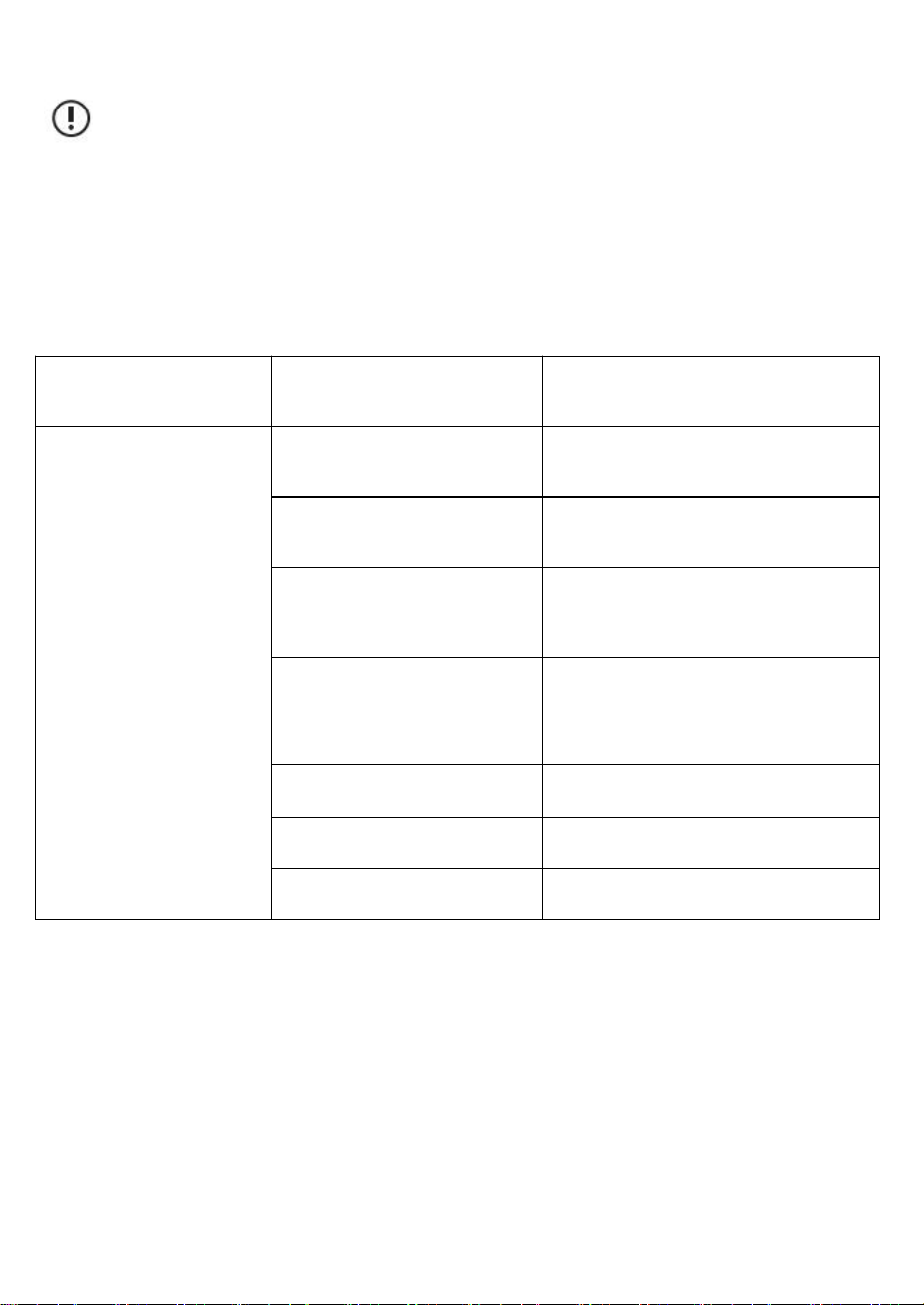
13
Attenzione:
1. Quando l'apparecchiatura causa malfunzionamenti, eseguire un
controllo autonomo seguendo uno per uno i punti sottostanti. Se ancora
non si riesce a trovare il problema, contattare il rivenditore o lasciare che
un professionista ripari il prodotto.
2. Non riparare autonomamente la ventola. Un utilizzo e una
manutenzione impropri possono causare scosse elettriche o incendi.
Descrizione del
malfunzionamento
Analisi
Metodi di eliminazione
La ventola non può
essere avviata o
azionata.
Interruzione di corrente
(autocontrollo).
In attesa della fonte di alimentazione.
Il dispositivo di protezione del
circuito scatta (autodiagnosi).
Riavviare l'alimentazione.
Controllare se la tensione è
troppo alta o troppo bassa
(misurata da professionisti).
Controllo da parte di professionisti.
La pala del ventilatore è
bloccata da oggetti estranei
(autocontrollo).
Spegnere e rimuovere gli oggetti
estranei. Le operazioni ad alta quota
devono essere eseguite da personale
qualificato.
Cortocircuito.
Controllo da parte di professionisti.
Ustione del motore.
Controllo da parte di professionisti.
Bruciatura del condensatore.
Controllo da parte di professionisti.

14
La ventola produce
forti rumori e
vibrazioni quando è
in funzione.
Non installato saldamente
(autodiagnosi).
Reinstallazione e
fissaggio.
Il dispositivo stesso è allentato
(auto-controllo).
Lascia che sia il
professionista a
risolvere il problema.
La lama è ricoperta di polvere.
Difetti dei componenti causano
la variazione del carico
(autocontrollo).
Lascia che sia il
professionista a
risolvere il problema.
Il dispositivo è bloccato da
oggetti estranei (autocontrollo).
Spegnere e rimuovere
gli oggetti estranei.
Se la velocità del dispositivo
aumenta, verificare se la
tensione è troppo alta.
Controllo da parte di
professionisti.
Se la velocità del dispositivo
diminuisce, verificare se la
tensione è troppo bassa.
Controllo da parte di
professionisti.
Sanven Technology Ltd.
Indirizzo: Suite 250, 9166 Anaheim Place, Rancho Cucamonga, CA 91730