PIKO G-SmartControl
wlan
–
the digital future of
Garden Railway control systems!
USER MANUAL
System
2
RailCom
®
is a registered trademark of Lenz Elektronik GmbH, Gießen
RailCom Plus
®
is a registered trademark of ESU electronic solutions ulm GmbH & Co. KG, Neu-Ulm
PIKO reserves the right to make technical and/or color changes to this product. Errors and omissions are possible and
delivery dates are not guaranteed. Dimensions and illustrations are subject to change. Duplication and/or reproduction
of this document in any form without written permission of PIKO is prohibited.
35055-90-7001 PIKO Spielwaren GmbH © 08/2026
Dear PIKO fans,
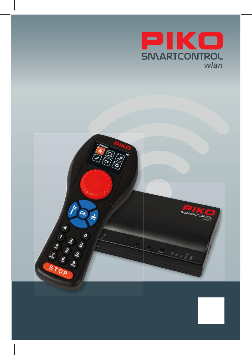
We are pleased to present to you the all-new PIKO G-SmartController
wlan
Digital Com-
mand Control System– an innovative and, above all, future-proof DCC system that was
developed entirely in-house and is fully tailored to the needs of model railroaders looking for
a convenient yet easy-to-use system for digital model railroad control.
Running trains, throwing switches, controlling signals, creating routes, and programming
CVs has never been so easy. The new PIKO G-SmartControl
wlan
is the perfect DCC
system for beginners and seasoned model railroaders alike. And, thanks to the PIKO G-
SmartControl
wlan
modular design, adding boosters is a snap for those wanting to expand
the size of their layout.
The Smart Controller’s throttle features easy-to-understand symbols clearly arranged on
the color display. This makes operating the SmartControlwlan easier and more intuitive than
traditional DCC systems. What's more, the PIKO G-SmartController
wlan
is designed in such
a way that it can be conveniently operated with one hand.
The PIKO G-SmartController
wlan
and PIKO G-SmartBox
wlan
are connected to each other
via a self-contained WLAN network.
This allows the operator freedom of movement around the layout.
A special feature of the SmartControlwlan system is it allows up to four PIKO G-Smart
-
Controller
wlan
throttles to be paired with one PIKO G-SmartBox
wlan
- for even more fun with
family, friends or on a club layout!
NOTE: The colors and shapes of the images and illustrations in this user manual correspond to the
original products only to the greatest extent possible.
wlan
3
PIKO G-SmartControl
wlan
User Manual
Table of Contents
System properties .................................................................................................................. 5
System connections................................................................................................................ 6
1. Putting the PIKO G-SmartControl
wlan
into operation ........................................................ 8
2. The controls of the PIKO G-SmartController
wlan
............................................................... 9
3. Operating of the PIKO G-SmartController
wlan
................................................................... 10
3.1. Start ....................................................................................................................................... 10
3.2. The main menu ...................................................................................................................... 10
3.3. The locomotive menu [
] ..................................................................................................11
3.4. The accessory menu [
] .................................................................................................. 13
3.5. The routes menu [
] ......................................................................................................... 14
3.6. The edit menu [
] .............................................................................................................. 15
3.6.1 Edit locomotive data ............................................................................................................. 15
3.6.2 Edit accessory ....................................................................................................................... 19
3.6.3 Edit routes .............................................................................................................................. 24
3.7. CV programming menu [
]............................................................................................... 30
3.7.1 CV programming on the programming track (PROG) ........................................................ 30
3.7.2 CV programming on the main track (POM) ......................................................................... 32
3.7.2.1 CV programming on the main track for accessory decoders ........................................... 33
3.7.3 CV programming on the main track (XPOM) for experts ..................................................... 33
3.7.4 Update menu for PIKO G-SmartDecoder XP 5.1 and further versions (PSD) .................. 34
3.8. The settings menu [
]....................................................................................................... 35
3.8.1 Setting the language ............................................................................................................. 36
3.8.2 Setting the Controller’s display brightness ........................................................................ 36
3.8.3 Setting the dial settings ........................................................................................................ 37
3.8.4 SmartController sleep mode ................................................................................................ 37
3.8.5 Select WLAN network
.......................................................................................................... 38
3.8.6 General settings (SmartController) .................................................................................... 40
System
4
3.8.7 The information menu ......................................................................................................... 42
3.8.8
Settings menu of the SmartBox (command station) ......................................................... 44
-
Track settings ....................................................................................................................... 44
- Extended settings ................................................................................................................ 45
- RailCom Plus
®
settings ........................................................................................................ 45
- PIKO G-SmartBooster (PSB) settings ................................................................................. 45
- Voltage settings ................................................................................................................... 45
- Key settings ......................................................................................................................... 46
- SD-card settings .................................................................................................................. 46
-
WLAN settings ..................................................................................................................... 47
-
System response to a lost connection ................................................................................. 49
3.8.9
Limiting access to individual controller menus (child safety lock) ................................. 49
4. RailCom Plus
®
...................................................................................................................... 50
5. Firmware update .................................................................................................................. 50
6.
Technical data ...................................................................................................................... 51
a. PIKO G-SmartBox
wlan
........................................................................................................ 51
b. PIKO G-SmartController
wlan
............................................................................................. 51
EU- Declaration of Conformity / FCC Notice ...................................................................... 51
7.
Product safety warnings ..................................................................................................... 52
8. FAQs ..................................................................................................................................... 52
9.
Technical hotline .................................................................................................................. 52
wlan
5
PIKO G-SmartControl
wlan
is a Digital Command Control (DCC) system designed for model railroaders
of all skill levels. It consists of the PIKO G-SmartController
wlan
handheld throttle and the
PIKO G-SmartBox
wlan
command center which are connected to each other via WLAN.
With PIKO G-SmartControl
wlan
DCC locomotives can be controlled, accessories can be switched, and
even routes can be triggered. It provides all the functions required for convenient digital model railway
operation.
The PIKO G-SmartBox
wlan
serves as the heart of the PIKO G-SmartControl
wlan
system. Clearly
labeled buttons and ports ensure smooth operation while colored LEDs give you a quick overview of
the system status.
The PIKO G-SmartController
wlan
is a state-of-the-art wireless handheld throttle for the
PIKO G-SmartControl
wlan
system. Up to four SmartControllers can be used simultaneously on a single
PIKO G-SmartBox
wlan
.
The shape and weight distribution of the PIKO G-SmartControllerwlan are designed so that it ts
perfectly in your hand. The buttons and keypad are arranged such that everything can be controlled
with one hand; whether for right-handed or left-handed individuals.
System properties
• Up to 16 locomotives can be controlled individually or as part of a consist. An almost unlimited
number of locomotives can be managed on the SD card.
• The PIKO G-SmartControl
wlan
is RailCom Plus
®
compatible, so all locomotives and rolling stock
equipped with RailCom Plus decoders will automatically register with the system.
• The PIKO G-SmartBox
wlan
supports the 14, 28 and 128 speed step format.
• The data format can be set individually for all locomotive addresses.
• Up to 69 functions can be activated for each locomotive address.
• For vehicles equipped with special LGB decoders, special locomotive functions can also be output
serially in the DCC14 format (DCC14S).
• The system allows up to 128 accessories with addresses ranging from 1 to 2048.
• The PIKO G-SmartControl
wlan
system features a route memory for up to 18 dierent train routes.
The accessories can be grouped into routes of 9 control commands each.
• Any accessory addresses between 1 and 2048 and pause steps can be inserted in each track.
• The command station delivers a 5 A output to the main track and features short circuit and
overload protection. This enables multi-train operation without having to use additional boosters
(PIKO Booster).
• The PIKO G-SmartBox
wlan
has a separate programming track output. When programming on the
programming track, the main track output is switched o.
• The PIKO G-SmartControl
wlan
supports both the programming track as well as programming on the
main track (POM and XPOM) for DCC-Decoder.
• PIKO G-SmartDecoders from version XP 5.1 and upwards can be updated with SmartControl
wlan
• All PIKO G-SmartControl
wlan
components can be updated.
• The PIKO G-SmartControl
wlan
can be operated via WLAN in AccessPoint mode (the system’s self
contained WLAN network), or by integrating the system into an existing home network in Station
mode.
System
6
System connections
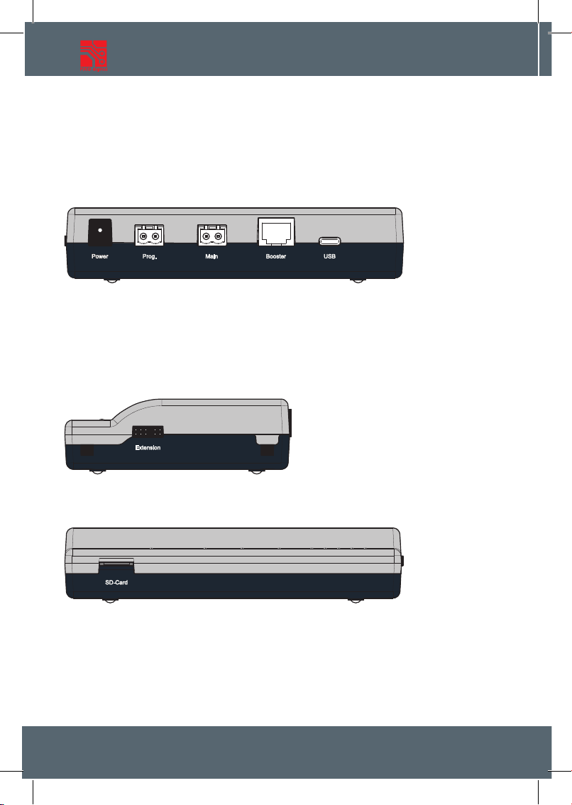
The PIKO G-SmartBox
wlan
has ports for a main track, a programming track, a PIKO G-SmartBooster,
as well as USB-C port and a socket for the power cord.
Connection points on the PIKO G-SmartBox
wlan
Back side
Power: Connection port for the 22V DC power cord
Prog.: Port for the programming track (only for decoder programming, no traction voltage)
Main: Port for the main track with DCC digital voltage
Booster: Connection port for PIKO-SmartBooster
USB: USB-C port for PSCw app and rmware updates (cable included)
Right side
Extension: Connection port for SmartController
wlan
accessories
Front side
SD-card: Slot for the micro SD-card
The included micro SD-card is used to store locomotive images and to transfer updates to the control
unit. In addition, the information stored in the system about locomotives, accessories and routes can be
saved on the micro SD-card and
later transferred back to the SmartController (backup function).
The SD-card must be inserted to provide all functions of the SmartControl
wlan
system.
wlan
7
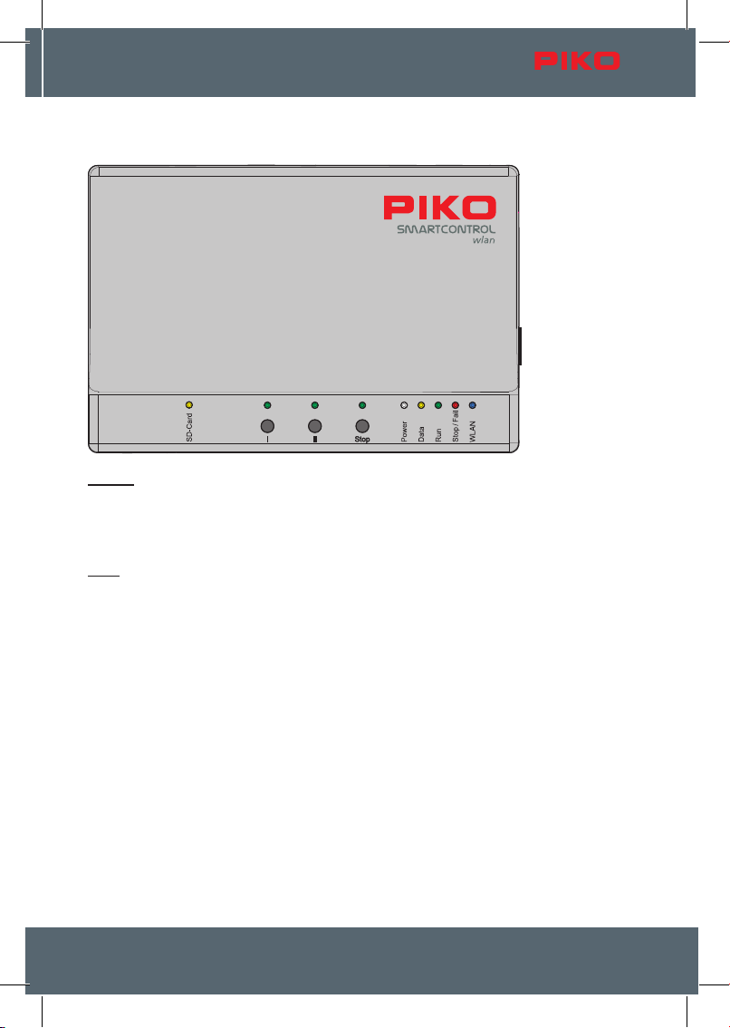
Controls and display elements of the PIKO G-SmartBox
wlan
G-
Buttons
I:
Open use button (you can program this button for any function you want)
II: WLAN "Fast Connect" (adjustable)
Stop: Track power o / on
A long press on start-up resets the SmartBox to factory settings.
LEDs
SD-Card: SD-card data transfer
I: Button I on/o
II: Button II on/o
Stop: Stop button on/o
Power: System is powered on
Data: SmartController is receiving data
Run: Main track is switched on, blinking if Prog. track is switched on
Stop/Fail: Main track is switched o / system fault
WLAN: WLAN on / o
System
8
1. Putting the PIKO G-SmartControl
wlan
into operation
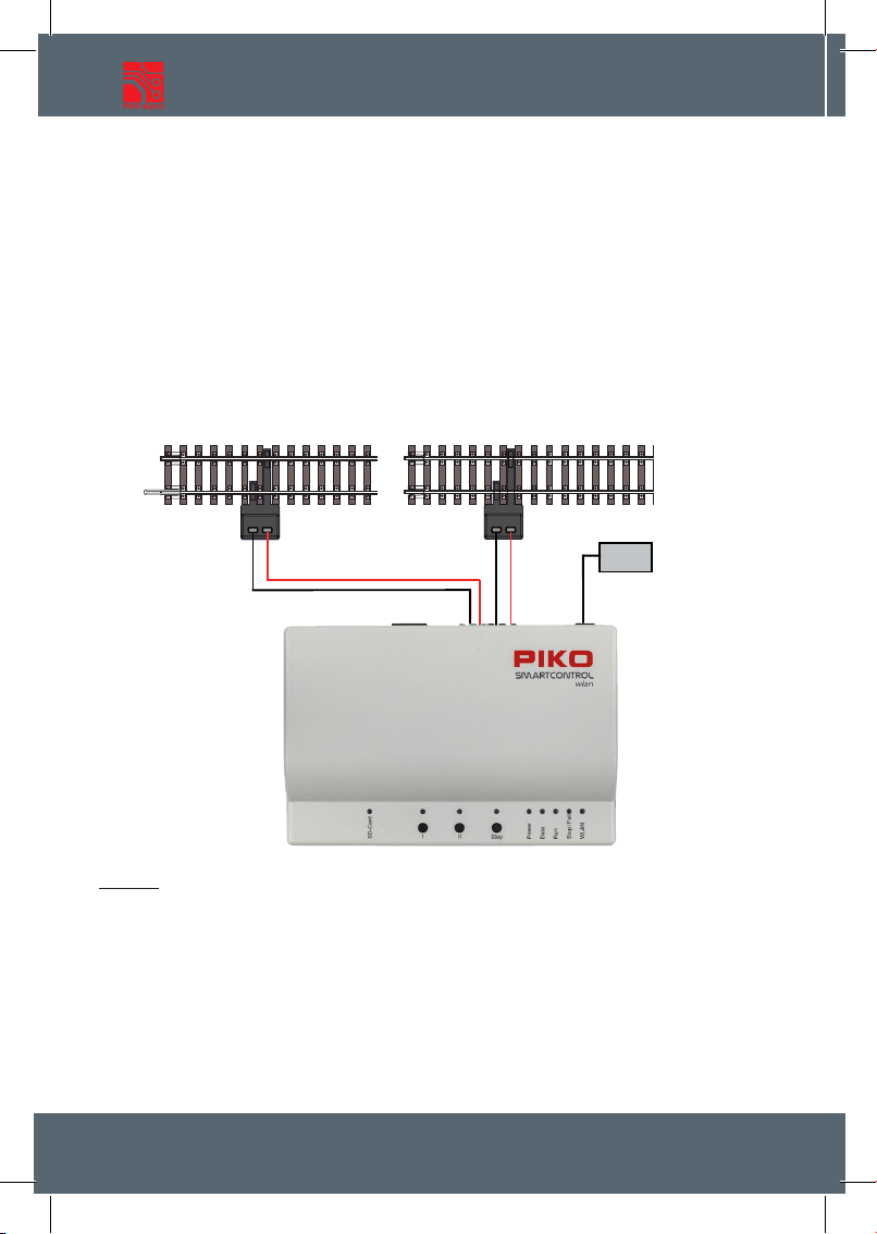
First connect the main track port (Main) of the PIKO G-SmartBox
wlan
to the main track and, if neces-
sary, the programming track port (Prog.) to the programming track. The main and programming tracks
must not have any electrical connection to each other.
Make sure the SD-card is fully inserted into the SD-card slot.
Now turn on the operating voltage by plugging the power supply cord to the PIKO G-SmartBox
wlan
.
The following control LEDs will now illuminate: SD-card (yellow, brie y), Power (white), Stop/Fail (red)
and WLAN (blue; blinking).
Now insert the included battery into the battery compartment on the back of the PIKO G-SmartCont-
roller
wlan
. Make sure the battery is oriented correctly to its contacts. Reattach the battery compartment
cover with the enclosed screw. The PIKO G-SmartController
wlan
switches on automatically. If the
battery is already inserted and the throttle turned o , press and hold the "STOP" button for approx. 3
seconds to turn the throttle on again. After the PIKO start screen, the locomotive selection menu will
appear on the display and the "STOP" button will ash (track voltage is turned o ).
Netzteil
22V-
Main
Prog.
Caution:
The SmartController throttle and SmartBox are not paired to each other from the factory. There is no
WLAN connection and the WLAN symbol on the throttle’s display is crossed out!
The rst step now must be to activate the WLAN connection (pairing). If both devices have not
been used before, please carry out the "FastConnect" function by following the instructions on the
SmartController’s screen and pressing and holding button II on the control panel until the "run" and
"Stop/Fail" LEDs ash in sync. Then con rm the information screens on the throttle´s display within
30 seconds with "yes". You can switch between "yes/no" by pressing the "left / right" buttons and
con rm your setting with the button "OK".
wlan
9
The devices are now paired when the two LEDs on the control panel stop ashing and the active
WLAN symbol appears on the throttle.
More information on "FastConnect" can be found in Chap. 3.8.5 "Select WLAN network".
2. The controls of the PIKO G-SmartControl
wlan
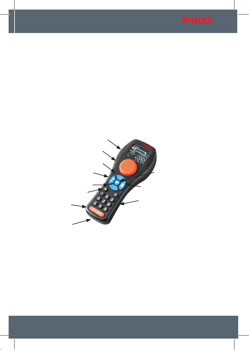
Overview of the controls
Display
The PIKO G-SmartController
wlan
features an illuminated TFT color display that can be adjusted to the
user’s preference. The symbolism is designed for intuitive control and is largely self-explanatory. Each
icon is clearly marked for easy use of the PIKO G-SmartControl
wlan
digital system.
The WLAN signal strength, throttle ID and battery level are displayed in every menu on the top line
of the display. Depending on the application there will appear an hourglass (data is being loaded
or processed), the letters "ABC" or "abc" to distinguish between upper - and lower-case letters, the
letter "R" will appear to signify RailCom Plus
®
registration and, the letter "P" will appear during CV
programming mode via the programming track and the letter "S" (STOP) for the track voltage being
turned o.
USB-C
Accessories / left
Numeric keypad
Display
Dial (throttle)
up
down
return
stop / go
Loco / right
OK
System
10
Throttle
The throttle features endless rotary dial control for setting the speed, changing direction of travel and
emergency stop for the currently active locomotive (double-click).
Adjustable for AC drive controller mode (factory setting) and DC drive controller mode (chap. 3.8.3).
Buttons
The backlit keys of the PIKO G-SmartControl
wlan
keyboard allow all control steps to be performed
comfortably. The durable keys have a clearly perceptible pressure point and are nearly wear-free. The
brightness of the keyboard backlight can be adjusted to suit individual needs.
USB-C port
The PIKO G-SmartControl
wlan
contains a USB cable that is used to charge the system via the USB-C
port. Charging is also possible while driving. For this purpose, a suitable power supply (5V DC, 1A, not
included) with a suitable USB cable can be used.
3. Operation of the PIKO G-SmartController
wlan
3.1. Start
After the controller is switched on, it is in the track selection menu and the "STOP" button is ashing
(track voltage switched o).
The "STOP" button can now be used to switch on the voltage at the main track output ("STOP-Button"
light will switch o and the "Run" LED on the SmartBox will light up green).
The track voltage can also be switched o at any time via the "STOP" button or the "Stop" button on
the SmartBox.
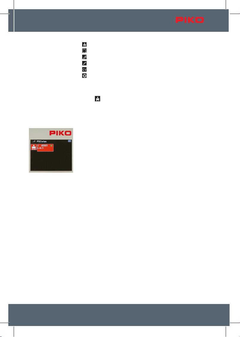
In this locomotive selection menu, all locomotive data sets can be found that have already been
created via the editing menu, or have been automatically generated via RailCom Plus® capable
locomotives. DCC locomotives are factory-set to address "3" and will show up on your system as "3"
until you give the locomotive a new address.
In the true plug-and-play spirit, you can start operating your model railway immediately, provided
that the locomotives used are equipped with RailCom Plus® compatible decoders such as the PIKO
G-SmartDecoder XP. These decoders automatically register with all the data belonging to the vehicle
on the PIKO G-SmartBoxwlan after the track is laid and the track voltage is switched on via the "STOP"
button and can be operated directly.
NOTE: During operation, the throttle may display information windows. These windows can be
closed with any key, or they will disappear automatically after about 10 seconds. Please observe the
information displayed as appropriate.
3.2. The main menu
The menus for controlling rolling stock and accessories as well as device settings are available under
the main menu.
The menus displayed can either be selected with the keypad using their associated number (top left in
the menu eld) or selected using the navigation buttons (up / down / left / right) and then conrmed with
the "OK" button .
wlan
11
1 [ ]: Locomotive menu (for selecting available locomotives)
2 [
]: Accessories menu (for selecting available accessories)
3 [
]: Routes menu (for selecting train routes you have created)
4 [
]: Edit menu (for editing locomotives, accessories and train routes)
5 [
]: CV programming menu (CV-programming and decoder updates)
6 [
]: Settings menu (for selecting device settings)
You can return to the main menu from each of these menus by pressing the "back" button.
3.3. The locomotive menu [ ]
In the locomotive menu, you can choose from all available locomotives which one you want to operate.
Up to 16 locomotives can be run simultaneously. If a locomotive is selected and is currently running on
the layout, you can still switch to another one. The previous locomotive will continue to run at the
parameters you left it at until you select it again and change them.
To begin operating a locomotive with the PIKO G-SmartController
wlan
you
rst call it up from the locomotive selection list by pressing the number key
that matches the locomotives address (found in the top left of the eld). The
locomotive menu is factory set to locomotive address "3". The locomotive
can also be selected by using the navigation buttons (up / down / left / right)
and pressing the "OK" button.
Locomotive Call via Decoder Address: By pressing the "down" button for
about 2 seconds, you can select a locomotive by its decoder address.
A eld will appear where you can enter the desired locomotive address;
select "Save" to complete the process. This locomotive will now be
temporarily available in the locomotive selection until the control unit is
turned o.
If more than six vehicles are available, two triangles appear next to the
vehicle elds. The lled-in triangle indicates the direction in which additional
locomotive records can be accessed using the "up" or "down" buttons. If the
desired locomotive is not in the list, it must rst be created in the locomotive
data editing menu (Section 3.6.1).
If the selected locomotive has not yet been called up by this controller and
the "Last command applies" option is not enabled in the controller's settings
menu, a conrmation window will appear asking whether the locomotive
should be selected. If the answer to this question is "Yes," the system rst
checks to see if any other controller is currently controlling this locomotive.
If no other controller is controlling this locomotive, it is taken over immediately. If this controller was the
last one to access the locomotive, a green dot appears in its locomotive eld, indicating that it is
immediately available.
Once the desired locomotive has been selected, it can be controlled directly
using the large speed control knob. This speed control knob, which has no
limit stop, automatically adopts the saved speed of the newly selected
locomotive when switching locomotives.
The locomotive image previously saved in the locomotive editor appears on
the display; below it on the left is the selected speed level with a direction
arrow, along with the speed bar below it.
If the direction arrow points to the right, the locomotive moves forward; if it
points to the left, the locomotive moves backward. When the speed control
is turned to the right, the locomotive moves in the indicated direction at an
System
12
increasing speed. Pressing the dial reverses the direction of travel when the speed is set to zero. If
the dial is pressed once while the locomotive is running, the locomotive will stop at its programmed
deceleration rate. Only when the speed control is pressed again will the direction of travel be reversed.
(Like with AC throttles). If the dial is pressed twice quickly while a locomotive is running, the locomotive
stops instantly without any braking delay. Whichever DCC speed step setting the locomotive is
programmed for, 14, 28, or 128, will be displayed under the speed bar. Below the speed bar the
locomotive address and name are displayed. The current status of all available locomotive functions
is found in the right half of the display. If a function is switched on, the corresponding function icon
displays a colored background.
Locomotive functions are activated using the SmartController’s keypad. The
light function (F0) is always activated using the "0" key. For all other
functions, the eld in the display screen shows which keypad button to press
to activate a function.
The two triangles to the left of the function eld indicate whether additional
functions are available. If the triangle is solid white, you can scroll line by
line in the corresponding direction of the triangle by using the "up" or "down"
keys. Whether more additional functions are available depends on whether
they are dened for this locomotive data record.
DC Speed Control Mode
If the speed control is turned to the right from speed level zero, the locomotive moves forward in the
direction of travel at an increasing speed. If the speed control knob on the PIKO G-SmartControl
wlan
is turned counterclockwise, the locomotive's speed is reduced until it comes to a stop. Turning the knob
further counterclockwise accelerates the locomotive in the opposite direction. DC speed control mode
can be enabled in the controller's settings menu (Section 3.8.3, "Conguring Speed Control Behavior").
Additional functions
DCC Direct: If the “Down” button is pressed
and held for 2 seconds in the locomotive
control menu, a non-RailComPlus-compatible
decoder that does not register automatically
can be used temporarily by entering a
locomotive address. This allows a locomotive to
be controlled directly without rst having to
create a complete locomotive data record.
Double-Heading: If the “Down” button is long pressed a second time, a second locomotive (the
traction locomotive) can be selected and coupled with the locomotive currently assigned to the
locomotive controller (the base locomotive) to form a double-heading consist. The consist is indicated
by a symbol showing two locomotives. To dissolve a double-heading consist, the base locomotive is
coupled with itself, i.e. the base locomotive is selected as the traction locomotive.
wlan
13
Speedometer reading:
If you press the "down" button in the speed controller menu once more for
about two seconds, the display switches to a DEUTA "speedometer display"
showing the speed levels. The "F0" function can also be switched here.
Pressing the "back button" or the "down button" for approx. two seconds
switches back to the standard display.
3.4. The accessory menu [ ]
The SmartControl system will accommodate up to 128 DCC accessories
with addresses between 1 - 2048 (up to 54 addresses in the StartSet
version). Symbols (icons) are available for accessories such as street lamps
up to four-aspect illuminated signals, which must be switched via three
dierent DCC addresses. The accessory menu automatically recognizes
RailCom® accessory decoders. The SmartController is not pre-programmed
for any specic accessory, so they must be entered into the system via the
"Edit accessory" menu. (see chap. 3.6.2)
Once an accessory is entered into the SmartControl system, it can be
selected on the SmartController by using the keypad (matched to the
accessory’s icon on the display) or by highlighting the accessory’s icon using
the navigation keys and pressing
"OK".
Note: While in Accessory mode, the locomotive that was last being operated
will continue to be operated by your throttle. The name of the locomotive, its
speed and direction of travel will continue to be displayed in the lower left
corner of the display. Switching the throttle to accessory mode does not
mean that you lose control of the locomotive you were operating..
If an accessory is called up, its settings are displayed on the screen and can be switched directly via
the keypad or the navigation buttons and subsequently conrmed by pressing "OK".
Multi-aspect signals, three-way turnouts and slip switches (turnouts/crossovers) with multiple drives
can be switched at the same time using just one command. The accessory menu will then display them
according to their current position.
System
14
Signal Position Feedback via RailCom
®
If RailCom-compatible switching decoders are used (e.g., PIKO SD 2000),
adjusting the turnout drives during operation is indicated by a "!" symbol on
the display of the corresponding turnout. If the turnout position is now
corrected manually using the turnout actuator or by directly setting the
turnout address, the "!" symbol will also disappear.
Switching accessory addresses directly
The accessories menu allows you to switch an accessory that has not yet been programmed into
the SmartControl system. This is convenient for testing some accessory decoders or for testing out a
train routing. To do this, enter the accessory menu and press the "up" button for approx. 2 seconds.
Enter the desired switching address in the "Address" eld and conrm by pressing "OK". You can now
switch the accessory directly using buttons "1" (red) or "2" (green). The elds "R" and "G" can also be
selected via the navigation buttons and then conrmed by pressing the "OK” button. This will switch the
accessory. During switching, the relevant eld (R or G) displays a colored background, and no other
switching command can be triggered at this time.
3.5. The routes menu [ ]
The routes menu is used to send a sequence of commands to digital accessories like turnouts with the
push of a button. It makes operating a complicated track plan much easier, where, for example, a train
may need to leave a large station and three-way turnouts and multiple-aspect light signals need to be
switched at the same time. In this situation, at least four switching commands would have to be sent at
once.
You can access the route menu by selecting option "3" from the main menu
or by using the navigation keys followed by the "OK" button.
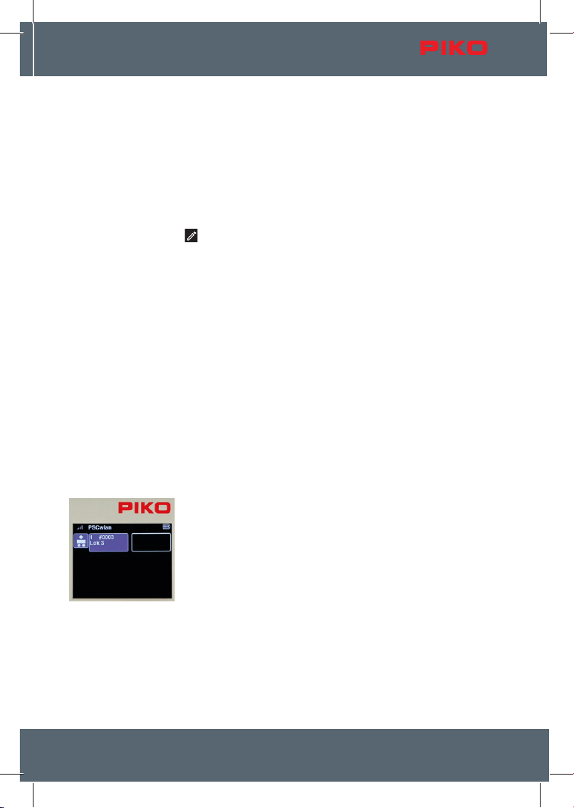
This menu supports a maximum of 18 routes, each with 9 commands (3 sets
of 6 in the starter set).
Routes can consist of a sequence of various control commands for
accessories, pause commands, and the activation of other routes (sub-
routes). They can be provided with two-line designations and thus there are
hardly any limits to creativity for the routes to be created.
wlan
15
No routes are preinstalled by default. These must rst be created using the
route editing menu (chap. 3.6.3).
If multiple routes are stored, they can also be activated using the number
keys according to their position on the display, or using the navigation keys
followed by the "OK" button.
When a route is activated, the eld for that route ashes until all the route’s
control commands have been sent.
NOTE: The last locomotive controlled can still be controlled using the speed
control. The speed setting, direction of travel, and the name of this
locomotive are displayed here in the lower left corner.
3.6. The edit menu [ ]
Using the Edit menu, you can program the PIKO G-SmartControl
wlan
with
data for locomotives, accessories, and route settings. To do this, enter the
appropriate information for the specied areas as desired and as needed.
You can also use the Edit menu to modify and save data in the desired
menus at a later time.
Since the icons in these application menus and the editor menu are the
same in places, their eld color changes from red to blue to avoid any
confusion.
In the editor menu, the application menu whose data is to be edited can be
selected using the keypad or the navigation keys and conrmed by pressing
the "OK" button.
Here you can select the "Locomotive menu", the "Accessories menu" and
the "Route menu".
3.6.1 Edit locomotive data
After calling up the locomotive menu, the vehicles currently available in the
system are displayed, along with an additional eld (maximum of 16). Using
this selection, you can now decide whether to modify an existing locomotive
record or create a new one. The desired locomotive is selected using the
keypad or the navigation keys and conrmed by pressing the "OK" button.
If you want to edit a locomotive data set that has previously been edited yet
the particular locomotive has not been run by your throttle during the current
operating session (no green dot), the screen will display a message asking
whether this locomotive should be requested from the command center. If
necessary, this must be answered with "Yes". If this locomotive data set
does not need to be edited, use the navigation key to change your answer
to "No" and conrm with the "OK" button.
System
16
If you wish to create a new locomotive data set, you should select an empty locomotive data eld using
the keypad or navigation keys followed by the "OK" button.
After making your selection, you can use the navigation keys to choose
whether to edit, save, or delete this record, or to import an existing record.
To edit the record, select the "Edit" eld and conrm with the "OK" button.
In the following example, we will create a new locomotive data record for the BR 83.10 steam
locomotive. This locomotive is not RailCom Plus®-compatible. It will be congured in DCC format with
28 speed steps, locomotive address 4, the locomotive name "BR 83.10," and several function keys.
Since this is a new locomotive data set, we choose an empty locomotive
data eld, whose DCC address appears as "0".
Editable data elds are always highlighted in blue. In the rst step, the
locomotive image is highlighted with the blue editing frame. If you wish to
change the image, press the "OK" button. If not, scroll down to the next
highlighted frame
To select the image for the BR 83.10, we scroll to the "PIKO" option and
select it, as all PIKO locomotive images are available under the PIKO option.
If a message appears about a non-existent image (while the SD-card is
inserted), please use the bottom menu option "Update" to display the entire
image database.
RailCom
®
locomotive images and your own customer-specic images can be
saved to the image database. Your own pictures must rst be saved to the
SD-card using the PSCw app in order to automatically get the correct display
size.
All PIKO locomotive images are now available for selection. You can scroll
through the list page by page using the "up/down" navigation keys.
You can also start a search by initial letter. To do this, rst press the number
key "1" (the letters "ABC" will appear on the top line of the display), and then
select the desired letter using the keypad.
When the page with the "BR8310" entry appears, use the navigation key to
move "right" to the selection of the four locomotives listed.
Now highlight "BR8310" with the "down" button and then conrm with the
"OK" button.
wlan
17
The locomotive image is saved when the "save" symbol is selected and
conrmed with the "OK" button.
The display then jumps back to a list of other locomotive data.
The new locomotive image for the BR 83.10 retains a blue editing frame and
can be changed again if desired.
To set the DCC speed levels, use the "down" button to switch to the speed
level display below the speed bar. It will now be highlighted in blue.
Pressing the "OK" button opens the selection menu for the DCC speed
steps.
Now select the desired number of speed steps using the "down" button and
conrm with the "OK" button.
DCC 14S refers to the serial output of locomotive functions (LGB).
For convenient speed controller operation, DCC 28 speed steps are
generally used.
NOTE: If you select the DCC 14 setting, which was commonly used in the past, the lights will not
function properly with current decoders because they will turn on and o with each speed step. In this
case, you must adjust the decoder’s CV29 setting accordingly (CV29, Bit 1 = 0).
To set the locomotive address corresponding to the locomotive decoder
being used, press the "down" button after setting the speed level to highlight
the locomotive address eld in blue.
By pressing the "OK" button, the previous address becomes a sequence
of gray zeros, which can now be overwritten with the desired locomotive
address.
As with previous data entry, the address is saved by pressing the "OK"
button.
Now you can also change the locomotive name. To do this, use the "down
arrow key" to navigate down one more line, which will highlight the current
name in blue.
Press the "OK" button” to display the name in gray.
Using the "left" navigation key, you can now delete it character by character.
Then enter the desired locomotive name using the numeric keypad, just like
on a telephone keypad.
If you want to switch between upper and lower case letters (the active
spelling appears in the top line of the display "abc / ABC"), you can do so by
using the "down" key.
Special characters can be found under the "0" and "1" keys. A space is
inserted with the "right" navigation key.
0: 0 . : ; % & [ ] { } ~ ` | #
1: 1 , ! ?-_+ / ( ) @$ ' " *=<> \ ^
Finally, the entry is conrmed by pressing the "OK" button.
System
18
In each locomotive data record, the function keys can also be modied. You
can swap function keys, change symbols, and even create new function
keys up to F68.
To change the functions of the current locomotive, press the "right"
navigation button. Now all functions are displayed in blue
3.10
By pressing the "OK" button, the two navigation arrows next to the function
key eld turn blue and the functions to be changed can now be selected via
the keypad.
If functions other than those shown are to be changed, you can use the "up"
or "down" keys to scroll line by line to the desired area. The solid navigation
arrow indicates the direction in which you can scroll.
3.10
Swapping two function keys is achieved by rst highlighting one of the two
function keys using the keypad (eld turns blue). The second function to be
exchanged is then selected with the keypad.
In the example shown, it would be the function keys "F2" and "F3", if the key
"F3" were now pressed.
3.10
To change the symbol/icon of a function key, rst highlight it using the
keypad and then press the "OK" button.
A total selection of 46 function symbols will now appear which you can scroll
through using the "right" and "left" navigation keys.
3.10
Once you reach the desired symbol, you can choose whether the function
will be a one-touch momentary function or a function that stays in operation
as long as the symbol is highlighted. To assign a momentary key function
(m), use the "up" or "down" navigation keys. A momentary function means
that the function is only switched on for as long as the function key is
pressed.
These settings are then saved by pressing the "OK" button.
wlan
19
3.10
In the example shown, "F3" horn function key has been changed to an "up /
down" symbol.
Once all the entries have been made for this locomotive, press the "back"
button on your throttle ...
... to save the new locomotive data set with the "Save" icon.
At this point you can also delete this locomotive data record by using the
"Recycle bin" icon.
The display then reverts to the locomotive editor icon of the editor menu. By
pressing the "back" button a second time, the display will return to the main
menu, where the locomotive can then be selected and tested via the
locomotive menu (chap. 3.3 "The locomotive menu").
3.6.2 Edit accessory
To add a digital accessory to the SmartControl system, you rst select the
accessories symbol in the editor menu by using key 2 or by using the
navigation keys followed by the "OK" button.
The next screen displays the accessories that have been entered so far, as
well as an additional, empty eld.
By default, no accessories are pre-entered.
In this example, we will add a left-hand turnout to the empty eld and
designate it "W4".
The empty eld for this new accessory is now highlighted by using the "5"
key or the navigation keys and conrmed with the "OK" button.
System
20
The following illustration shows symbols available for various accessories.
The left-hand turnout icon can now be selected using key "2" or the
navigation keys.
Here, too, the blue navigation arrows indicate that additional options are
available in the corresponding direction, which can be accessed using the
"up" or, as shown here, "down" button.
Various steps can now be selected in this view. The rst step is to enter the
name and a brief description of the item.
To do this, select the "Name" eld and conrm it with the "OK" button.
The name will appear later in the accessories menu as an identier for
selecting the accessory and the description will appear when the desired
item has been called up. After the "Name" eld has been selected with the
"OK" button, it is highlighted in blue and marked for entry with the "OK"
button.
The name is entered using the "telephone keypad" and is a maximum of 4
characters long. To switch between upper and lower case letters, press the
"down" key. The active case notation can be found in the top line of the
display as "ABC" or "abc". The name entry is then completed with the "OK"
button.
The input eld for the accessory description will now be framed in blue by
pressing the "down" button and marked for input with the "OK" button.
A short two-line description can be entered in the text eld.
The description is conrmed by pressing the "OK" button.
Use the "back" button to proceed to the next entries.
wlan
21
You can now use the "down" button to scroll to the "Type" entry and then
select it with the "OK" button. Various switching options are available here,
which can be activated depending on the type of decoder used.
The "Simple" entry is certainly the most common type and also the factory
default setting. The desired decoder type is selected with the "up" or "down"
button and conrmed with the "OK" button. The corresponding eld is then
highlighted in green.
The rst entry, "RailCom Decoder," is used for RailCom®-compatible
accessory decoders, such as our new products SD 2000 (55032), RD 4000+
(55033) and others.
The entries “Advanced” and “Advanced Time” are intended for accessory
decoders that can be designated according to the RCN 213 standard. More
detailed information can be found in the respective accessory decoder’s
manual.
Use the "back" button and then press the "down" button to scroll to the
"Address" entry and select with "OK".
To ensure that the correct accessory decoder is addressed when activated
later, the desired switching address must be entered in this submenu. Use
the "right" navigation button to select the address eld and press the "OK"
button to activate it. You can now enter the desired address - in this case, ‘4’
- and conrm it by pressing the "OK" button.
Next, use the "down" button to select the lower eld for entering the desired
"switching time" and press the "OK" button to activate the entry.
The switching time is entered in 100-ms increments and determines the time
after which the control panel sends the turn-o command (pulse duration).
Conrm this entry with the "OK" button, then press the "left" navigation
button.
System
22
The two arrows next to the turnout symbol now appear in blue.
You can now use the "up" or "down" button to scroll to both directions for the
two turnout positions.
The turnout position (here it is diverging) to be set here "green / straight" or
"red / diverging" is shown in green in the turnout symbol.
The selection is now activated with the "right" navigation key. This can be
seen from the switching address now shown in blue.
You can now use the "OK" button to select the switching direction (shown
here in green for the direction straight). The selected setting is displayed in
color in the corresponding eld.
Once the rst direction has been set, you must now use the "left" button to
jump to the turnout symbol. The two arrows are now shown in blue again
and the "down" button highlights the second turnout position, which is also
shown in color in the turnout symbol (here it is the diverging track). Now
press the "right" button again to enter the turnout position and set it with the
"OK" button.
Use the “back” button to complete the address setting process.
IMPORTANT: At this point, the entries have not yet been saved. If you go up a menu level without
saving using the "back" button, a message will appear asking if you want to abort your editing. If you
answer "yes", the data set will not be saved.
To save your settings, use the navigation buttons "up" or "down" to go to the
"Save" option and conrm it with the "OK" button.
If an accessory that has already been saved is called up in the editing menu,
it can be deleted via the "Delete" option after answering a security query.
The display then jumps back to the selection of editable accessories.
The settings for accessories with multiple connections - such as three-way or double-crossing turnouts
with two drives, or three- or four-phase light signals that require more than one control address - are
briey explained here using a three-phase light signal as an example.
wlan
23
Select three-aspect light signal.
Enter name and description.
There is no need to enter the type, since the factory setting "Simple"
is used automatically here.
Enter the rst address for switching between red and green, followed
by the second address to turn yellow on or o. Then enter the
switching time in 100-millisecond increments.
If the accessory decoder being used is a RailCom-compatible
decoder (e.g., PIKO SD 2000), the "Type" menu is also opened and
the "RailCom Decoder" option is selected.
System
24
In the following steps, enter the red/green switching directions for the signal images shown and then
save the dataset.
NOTE: For technical reasons, the nal display order depends on the available open eld locations.
This means that when accessories have been deleted, the next newly created data set is automatically
saved in the eld location that was just deleted.
Therefore, the new item is not necessarily displayed at the
position that was shown when the empty eld was selected.
3.6.3 Edit routes
To create routes, select the route icon in the edit selection using the "3" key
on the numeric keypad or the navigation keys followed by the "OK" button.
A route can include a sequence of settings for the edited accessory items,
pause times, and previously edited routes - known as sub-routes. The
maximum number of entries per route is 9. Of course, this limit can be
signicantly exceeded if necessary by using the aforementioned sub-routes.
A total of up to 18 routes are possible.
wlan
25
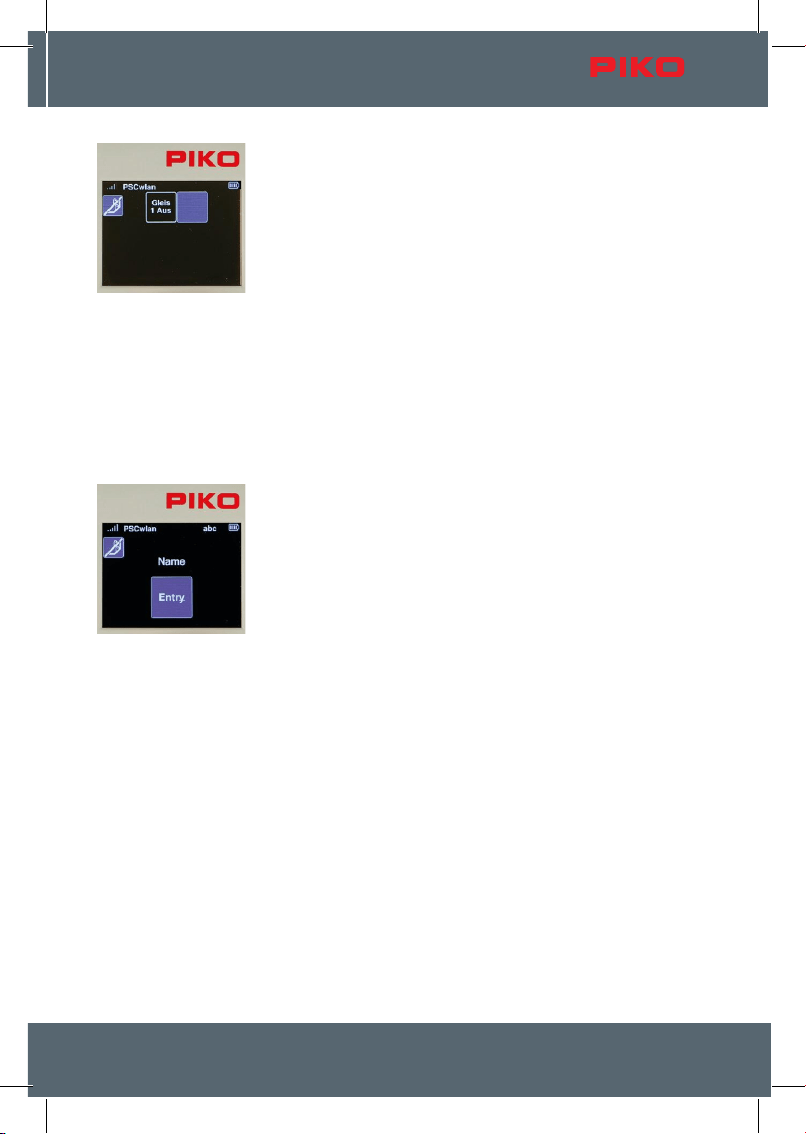
The next screen displays the routes entered so far, as well as an additional,
empty eld.
By default, no route is stored, so only the empty eld is visible.
To select the empty eld, use the navigation keys followed by the "OK"
button or the "2" key.
If routes already exist, the empty eld can be selected and activated using
the corresponding number or the navigation keys.
Like the editor menu for accessories, a selection menu will appear showing
each possible process.
For example, we will make a "station arrival" route. This route switches
turnout W4 to straight, the three-aspect entry signal LS12 to green (Hp1)
and after a pause of 50 seconds back to red (Hp0).
The rst step is to enter the name of the new route.
To do this, select the "Name" eld and conrm with the "OK" button.
After conrming the "Name" eld here as well by pressing the "OK" button,
you can now enter the new name using the phone keypad as usual and then
conrm by pressing "OK".
The "back" button takes you back to the selection menu of available editing
steps.
There, select the "Entries" eld and press the "OK" button to activate it.
The display changes to the nine input elds for possible route commands.
The rst eld is now highlighted for entering the rst switching command and
conrmed with the "OK" button
.
In the following view we can now decide which type of route command
should be entered as the rst step. There are "accessory circuits", "pauses"
and previously edited "routes" (sub-routes) to choose from.
The selection can be made using the navigation keys or using the number
shown in each eld.
Since the rst step is to issue a switching command for turnout W4, the
"Accessories" eld is selected here.
System
26
After the accessory symbol has been conrmed, the accessories already
entered into the system are displayed as options.
Left-hand turnout W4 is selected using key "3" or using the navigation keys
followed by the "OK" button
.
Now you can decide which direction to set the switch. The switch should be
set to "straight." To do this, either press key "1" on the numeric keypad, or
use the navigation keys to highlight the corresponding eld and conrm with
the "OK" button.
To keep the turnout drives from overheating, set a delay time in 100ms
increments in the input window that now appears and conrm it with "OK".
Finally, we highlight the "OK" symbol and complete this step by pressing the
"OK" button.
The rst step of our route now appears in the command sequence.
The next step is to call up light signal LS12. To do this, select the second
eld using the "2" key on the numeric keypad ...
wlan
27
... and then select icon "1" for the accessory in the next window.
Accessories already stored in the system are displayed again.
Light signal LS12 is selected according to its position using key "6" or by
using the navigation keys followed by the "OK" button.
Now you can decide which signal pattern to activate. Set the signal to
"green" (Hp1). To do this, either press key "2" on the numeric keypad, or use
the navigation keys to highlight the corresponding eld and conrm with the
"OK" button.
Next, enter a delay time in 100-ms increments, conrm it by pressing "OK",
and complete the entire step by clicking the "OK" eld.
Now this second step also appears in the sequence, and the next step is to
insert a fty-second pause. To do this, select the third eld using the "3" key
on the numeric keypad ...
System
28
... and in the next window, select the "2" icon to activate the pause step.
In the subsequent window, you can jump to the delay eld and select it with
the "OK" button.
Now you insert a pause time of 50 seconds in 1s increments and conrm it
with the "OK" button.
Then you highlight the "OK" eld and complete the entry by pressing the
"OK" button.
The third step of our sequence will now appear where at the end of the
route, entry signal "LS12" is set to red (Hp0) again.
To do this, rst select the fourth, still empty eld with key "4" or with the
navigation keys followed by conrmation with the "OK" button ...
... and then select icon "1" for the accessory item again in the next window.
From the list, select the "LS12" light signal using key "6" on the numeric
keypad or the navigation keys, followed by "OK".
wlan
29
Now you can decide which signal display to select. The signal should be set
to "red" (Hp0). To do this, either press the "1" key on the numeric keypad, or
use the navigation keys to highlight the corresponding eld and conrm with
the "OK" button.
Now enter a delay time in 100ms increments and conrm it with "OK" and
complete the entire step by highlighting the "OK" eld.
The next window displays all the control commands for the now-complete
route.
The last step is to press the "back" button to save the new route in the
following window via the "Save" symbol.
This window also allows us to delete a route (that has been called up in the
editing menu) by using the "Delete" icon.
The display will now change to the editor menu for routes. The new route is
displayed and, if desired, we can create another route using the empty eld.
Pressing the "back" button two more times takes you back to the main
menu, in which the newly created route can now be selected and tested via
the routes menu.
System
30
3.7. The CV programming menu [ ]
In the main menu, the "CV" icon is selected using key "5" on the keypad.
A CV (Conguration Variable) is a memory address in a digital decoder. The
content (value) of these CVs determines the behavior of the decoder. The
meanings of the respective CVs are found in the instruction manual of the
decoder.
The PIKO G-SmartControl
wlan
oers three types of programming for
decoder CVs:
1. Programming on the Main (POM)
2. Programming on the Main for Experts (XPOM) is a new type of
programming for experienced programmers
3. A programming track (PROG) is the traditional programming method
where the locomotive is placed on an isolated track dedicated just to
decoder programming.
The fourth menu (PSD) is intended for updating PIKO G-SmartDecoder from
version XP 5.1 and upwards.
3.7.1 The CV programming on the programming track (PROG)
Since programming on a programming track is the most common, it will be explained rst.
First place a locomotive with a CV-programmable decoder on the programming track.
In the programming menu, press the "3" key on the numeric keypad or use
the navigation keys to select the "PROG" menu, then press "OK."
This menu oers two options: CV programming only, or editing a
locomotive’s address, which can be read or changed.
CV programming can be accessed using key "3" and address editing using
key "4" on the numeric keypad, or by navigating to the respective option
using the navigation keys and then pressing "OK."
wlan
31
If address editing has been selected, the control unit’s green Run LED
ashes and a red "P" appears in the top line of the next display window.
Here, you can now read the current address and, if desired, change it to any
value in the address range from 1 to 10239.
Any necessary programming of CVs 17, 18 and 29 is automatically taken
into account and executed.
If CV programming has been selected, the green run LED on the control unit
ashes, and a red "P" appears on the top line of the next display window.
Use the navigation keys to jump to the "CV" eld and enter the CV number
to be read or written. To do this, rst press the "OK" button. The input eld
will now become solid. Now enter the CV number using the keypad and
conrm it by pressing the "OK" button again.
CVs numbered 1 through 1024 can be edited.
If you want to read the CV, use the "left" navigation button to select the "read
out" symbol and conrm it with "OK".
NOTE: If a message is displayed saying "Prog. Tr. is occupied, please
wait.", the programming track is currently being used by another controller
and cannot be accessed by this controller.
The read value is now displayed in decimal form in the "Value" eld, and as
bits highlighted in red in the bit eld underneath. The "read out" eld is now
solid red. The meaning of the CV’s individual bits can be found in the
instruction manual for the decoder.
If the CV read out failed, the "Value" eld will display a "0" and the "Read"
eld will remain outlined in red.
If this CV is to be programmed with a dierent value, then select the "Value"
eld on the right-hand side and conrm with "OK". Now enter the desired
value, conrm with "OK" and select the "write" symbol on the left-hand side.
Complete this step by pressing the "OK" button.
The value to be written can be entered in decimal form in the "Value" eld
and in bit representation as bits highlighted in red. For bit-by-bit program
-
ming, use the "down" button to jump into the bit sequence, use the "left" and
"right" navigation buttons to select the desired bits and conrm each with the
"OK" button.
System
32
If the CV was written successfully, the "Write" eld will now turn solid red.
.
3.7.2 The CV programming on the main track (POM)
A prerequisite for main track programming is that the decoder address of the locomotive decoder to be
programmed is known. CVs cannot only be programmed but also read via the main track connection of
the PIKO G-SmartBoxwlan, provided that the decoder being used is capable of doing so via RailCom®.
NOTE: During main track programming, the currently active locomotive can continue to be controlled.
Call up the "POM" menu in the programming menu by pressing key "1" or
using the navigation keys followed by the
"OK" button.
Now go to the "Address"eld, press the "OK"
button, and enter the decoder address you want
to edit using the numeric keypad. Finally, conrm
by pressing "OK".
If you want to read the displayed CV, use the
"left" navigation button to select the "Read" icon
and conrm with "OK". You can enter CVs from 1
to 1024 in the "CV" eld.
The read value is now displayed in decimal form
in the "Value" eld and as bits highlighted in red
in the bit representation.
If the CV value is to be changed, use the naviga
-
tion buttons to navigate to the "Value" eld and
activate it with the "OK" button. Enter the new
value using the keypad and conrm it with "OK".
You can also change the CV bits in this window
(Chap. 3.7.1 " ... programming track (PROG)").
wlan
33
Now use the "left" navigation button to select the
"write" symbol on the left-hand side, and nish by
pressing the "OK" button.
Other CVs can be programmed in the same way.
To leave main track programming, press the
"back" button. The display will again show the
programming menu.
During main track programming, the input and action elds behave the same way as they do in the
programming menu on the programming track. If a CV has been successfully read or programmed, the
corresponding action eld turns completely red here as well.
3.7.2.1 The CV programming on the main track for accessory decoders
In the POM menu, you can also access the main track programming for accessory decoders of the
PIKO G-SmartControl
wlan
. To do this, while the main track programming for locomotive decoders is
open, press the button with the turnout symbol for about 2 seconds.
The display now switches to the input menu for CV programming of
accessory decoders. If the decoder is an RCN-213-type decoder, the
"Advanced" option can be enabled here. Next, you must rst enter the
decoder address(!) before you can read or write a CV.
The programming itself is performed in the same way as main track
programming for vehicle decoders.
3.7.3 The CV programming on the main track (XPOM) for experts
The PIKO G-SmartControl
wlan
oers a relatively new type of programming method known as Program-
ming on the Main for Experts (XPOM). This is used to speed up access to CVs and to address the area
of the CV banks that can only be accessed via CVs 31 and 32. Up to four CVs can be written with one
command. If the decoder is RailCom®-enabled, the system can read four CVs at the same time. This
processing is done in decimal or hexadecimal notation.
PLEASE NOTE: The CV numbering starts with "0." So the "real" CV1 here is CV0, the actual CV29 is
CV28, and so on! The CV number you enter is therefore always the desired CV - 1!
To start the XPOM process, rst place a
locomotive with a known decoder address on the
main track.
In the programming menu, call up the XPOM
menu using key "2" or by navigating with the
navigation buttons and pressing "OK".
Now go to the "Address" eld, press the "OK"
button and enter the address of the decoder to be
edited using the keypad. Conrm with "OK".
System
34
The line CV basically consists of the values of the "pointer" CVs 31 and 32 (elds 1 and 2) and the
actual CV to be edited (eld 3). This CV is always between 0 (CV1) and 255 (CV256). If, for example,
the decoder instruction manual says "CV31 = 16, CV32 = 0 and CV257 = volume level value" for
setting the overall volume, then CV257 is the rst CV in this CV bank and is also entered here with CV
number 0.
For this example, the values of the three input elds would then be "16, 0, 0".
If the CVs are to be read from the "CV" line, then
use the "left" navigation button to select the "read
out" symbol and conrm with the "OK" button.
The values read from the four CVs are now dis
-
played in ascending order from left to right in the
"Value" elds in decimal or hexadecimal notation.
Here are the values for CVs 1–4.
If the values are to be changed, then use the
navigation keys to select the desired eld and
conrm with the "OK" button. Now enter a new
value using the keypad and conrm again with
"OK". Finally, use the "left" navigation button to
select the "Write" icon, and conrm by pressing
the "OK" button.
If you want the display to be in hexadecimal
format, use the navigation keys to select the
"Hex" eld and press the "OK" button to activate.
it. Values greater than 9 (A–F) can be entered using
the phone keypad or the "up" and "down"
navigation keys and conrmed by pressing the
"OK" button.
To exit the XPOM programming menu, press the
"back" button. The display will now return to the
programming menu.
3.7.4 Update menu for PIKO G-SmartDecoder XP 5.1 and further versions
(PSD)
This menu can be used to update PIKO G-SmartDecoders beginning with version XP 5.1. The latest
rmware can be found in the web shop on the PIKO website and can be copied to the SD-card.
To update the decoder, place the locomotive on the programming track.
After selecting the "PSD" eld, the next window will display the input eld for
the address of the desired decoder.
wlan
35
Enter the current address of the locomotive decoder in the "Address" eld.
To do this, select the address eld, press the "OK" button, enter the address,
and conrm with the "OK" button.
If the locomotive is on the programming track, the system will search for the
decoder and check its type. Once it is identied, the rmware version on the
SD-card that is compatible with this decoder type will be displayed, and only
then can the update be installed.
Once the decoder has recognized the signal, it will turn on its outputs A0f
and A0r (front and rear lights).
Click the "Update" button and press the "OK" button to start the update for
this PSD. Please do not interrupt the update process!
Once the update is complete, the progress bar will turn completely green
and the SmartBox will emit three short beeps. You can now exit the PSD
menu by pressing the "back" button, and the CV menu will reappear.
3.8. The settings menu [ ]
To assign settings in the PIKO G-SmartControl
wlan
devices, the "
" icon
for the settings menu must be called up in the main menu by using key "6"
or by the navigation keys followed by pressing the "OK" button.
This is where you’ll nd the settings options for, for example, the language
used (1), the controller’s brightness setting (2), general settings (6), and
even specic SmartBox settings (8).
If a PIKO G-SmartBooster is integrated into the system, the triangles for
scrolling appear next to the nine elds. You can then use the "down arrow"
key to navigate to the booster menu.
System
36
3.8.1 Setting the language
Currently, nine languages are available, and their respective alphabets are used in their character sets.
To change the language, select the rst eld
using the "1" key on the numeric keypad or by
navigating to it and then pressing "OK".
You can use the "up" or "down" navigation
buttons to scroll to the desired language and then
select it with the "OK" button.
To exit the language menu, press the "back"
button. The display now returns to the settings
menu.
3.8.2 Setting the controller`s display brightness
The Controller’s display brightness as well as the keyboard backlight
brightness can be set separately from each other.
To do this, press key "2" on the numeric keypad in the settings menu, or
navigate to this eld and activate the menu with the "OK" button.
The following window contains the settings for the display (left) and for the
keyboard backlight (right). You can switch between the two options using the
"right" and "left" navigation buttons.
The value in the active eld can be adjusted by turning the dial or using the
"up" and "down" navigation keys.
The changes are executed directly and thus allow immediate control.
After the changes have been made, the "back button" will return you to the
settings menu.
wlan
37
3.8.3 Setting the dial settings
The dial on the SmartController oers two types of speed settings and direction selection. These are
referred to briey as DC or AC speed regulator modes, since their modes of operation are based on
the analog DC speed regulators commonly used in the past for direct current operation and the AC
transformers used for alternating current operation (see chap. 3.3, "The locomotive menu").
To change these settings, press key 3 or use the
navigation keys to highlight this eld and activate
the menu with the "OK" button.
The following window displays the settings for DC
and AC (factory default), which can be selected
using the navigation buttons and conrmed with
the "OK" button (green eld).
The next line denes the maximum "double-click
time" for the throttle in milliseconds. If the dial is
pressed twice (double-click) within this time (max.
999ms), an emergency stop command is sent to
the active locomotive.
This window also contains the option "Last
command takes precedence." This is a setting for
operation with multiple controllers. If this function
is enabled, multiple controllers can access the
same locomotive address simultaneously, and the
command that was sent most recently—regardless of which controller sent it—will always be executed.
Once you've made all the settings, go to the "Save" eld and conrm by pressing the "OK" button.
The "back" button takes you back to the settings menu.
3.8.4 SmartController sleep mode
If the throttle has not been used for some time during an operating session, it makes sense to go into
sleep mode or shut down to conserve battery power. The time period between last use and activation
of sleep mode or shutdown is adjustable. These options are set here.
To do this, press key "4" in the settings menu or navigate to this eld and
activate the menu with the "OK" button.
System
38
The following window displays the settings for screen and controller
shutdown. Use the "down" and "up" navigation buttons to select the desired
options.
Use the "right" and "left" navigation buttons to select a time setting in minu
-
tes and conrm it with the "OK" button.
If the "--" eld is selected, this shutdown function will not be executed.
If the screen dims while the device is in use, you must rst press any button
on the controller to reactivate it before the next button press is processed.
If these settings are saved, pressing the "back" button will take you back to
the settings menu.
3.8.5 Select WLAN network
NOTE: If the SmartController cannot connect to a WLAN network after being turned on (the WLAN
symbol is crossed out), it will display a message asking if you want to use the "FastConnect" option.
Select the "Yes" or "No" option.
The desired WLAN settings can be entered into the WLAN settings menu of
the SmartController.
To do this, press key 5 in the settings menu or navigate to this eld and
activate the menu with the "OK" button.
Initially, the "Search" eld is selected. After conrming with the "OK" button,
the next window displays an option to choose whether to connect the
controller directly to an available SmartBox via "FastConnect" (a quick
connection) or to select a device from a list of available WLAN devices.
Here, you can choose "FastConnect" to connect to a powered-on SmartBox,
or "List" to view available WLAN networks.
To select "FastConnect", highlight the eld with the "OK" button. A message
now appears saying "Transfer access data". Please wait for this to clear and
then follow the instructions in the display.
wlan
39
Answer "Yes" to this prompt. If "No" is selected, use the "Left" navigation key
to select "Yes," then press the "OK" button to conrm.
Press and hold the "II" button on the SmartBox until the "Run" and "Stop/
Fail" LEDs ash in-synch. Answer "Yes" to the query within approx. 30
seconds.
The connection is established when the two LEDs on the command station
stop ashing and the active WLAN symbol appears on the display.
To select an available WLAN device, scroll to the "List" entry and conrm
with the "OK" button. All accessible WLAN devices will now be displayed.
The desired SmartBox will also appear in this list; select it using the "down"
or "up" navigation buttons and conrm with "OK".
The selected WLAN device now appears on the display. To change the
name of this WLAN device, press the "down" button; the active eld will
change from "Search" to the WLAN icon.
Conrm by pressing the "OK" button; the name eld will now be highlighted
in color, and you can change the name as desired using the phone keypad.
Then conrm the name entry by pressing the "OK" button.
The line with the "WLAN / lock" symbol can be selected here to enter the
WLAN password. Pressing the "OK" button opens the input eld, which
automatically enters a hyphen. If you want to exit this eld without making
any changes, rst use the "left" navigation button to delete the hyphen, and
then press the "back" button to exit the eld. If, on the other hand, you want
to set a password that is at least 8 characters long, rst use the "left"
navigation key to delete the hyphen; you can then enter the password using
the phone keypad and conrm it by pressing the "OK" button. The factory
password is "abcd1234".
System
40
Finally, click the "Save" button and then the "OK" button to save your entries,
and the screen will return to the settings menu so you can select additional
settings.
3.8.6 General settings (controller)
In the general settings menu, the throttle can be given a new name, you can
set the WLAN transmission intensity, assign a new PIN to block various
input and operating options and the Controller can be reset to the factory
settings.
To do this, press button "6" on the keypad in the settings menu, or navigate
to this eld and activate the menu with the "OK" button.
By selecting the rst eld "Controller Name" the window changes to the
name input eld.
You can now change the name in this eld as desired. To do so, press the
"OK" button to activate the name eld. Then enter the new name using the
keypad.
Once you have entered the name in full and conrmed it by pressing the
"OK" button, use the "Save" eld to save the new name in the controller. The
window will then return to the general settings.
In the submenu that follows, you can set the throttle’s WLAN transmission
power.
wlan
41
A range of values from 0 (low) to 10 (maximum) can be chosen here.
Select the menu to activate the input eld by using the "OK" button and
enter the desired value between 0 and 10 and then conrm it with "OK".
Finally, save this change via the "Save" eld in the display.
The window then returns to the general setting options.
You can assign a four-digit PIN number to the SmartController to protect
sensitive data input, or to limit the throttle’s applications (a child safety lock).
Select the "edit PIN" submenu to enter a PIN.
The factory-assigned PIN (0000) will be displayed on top of the solid red
eld while the new PIN is entered in the lower part of the solid red eld. The
new PIN is entered using the keypad and then conrmed with the "OK"
button. Incorrect entries can be deleted using the "left" navigation key.
If you want to leave the menu without making any changes, the "back"
button will take you back to the settings menu.
The last submenu allows you to reset the controller to its factory settings. To
do this, you’ll need the PIN you set earlier. The following controller settings
will be reset to their factory defaults: WLAN password, controller name, drive
controller mode, shutdown times, brightness levels, and the PIN;
additionally, the "locked" menus will be unlocked.
To reset the controller to factory settings, navigate to the "Factory settings"
submenu and conrm with the "OK" button.
Now enter your four-digit PIN and conrm with the "OK" button. Once the
Controller is rebooted it is restored to factory settings.
System
42
3.8.7 The information menu
The Information menu allows you to view a wide range of information about
the Controller, the track status and the SD-card.
It is accessed by pressing button "7" on the keypad (while in the settings
menu) or by navigating to this eld and selecting the menu with "OK".
Five submenus are displayed: "Track Monitor", "Firmware",
"Imagedatabase", "Search Online" and "Serial Numbers".
The Trackmonitor: This menu displays the current status at the SmartBox's
track output, including track voltage and operating temperature, as well as
the current (left value) and the peak current during this session (right value).
The green portion of the "current bar" shows the current power relative to
the maximum possible power. The red mark indicates the highest power
during the current session.
Firmware: This section displays the current rmware version of the controller
and the SmartBox, as well as the version currently available on the SD-card.
If the rmware version on the SD-card is more recent - that is, has a higher
number - you can use the "Update" option to update the controller and/or the
SmartBox. The latest rmware can be searched for and downloaded in
"Station Mode" when an internet connection is available, or it can be
downloaded from the PIKO Webshop and then saved to the SmartBox’s
SD-card.
wlan
43
The Imagedatabase: This displays the current version of the system's image
database and the version currently available on the SD-card.
If the version on the SD-card is more recent - that is, has a higher number
- you can update the image database by selecting "Import."
Search Online: To search online for newer rmware versions, the control
panel’s WLAN must be set to "Station Mode" (see settings menu 8,
“SmartBox settings,” -> WLAN settings).
If the online search is started without this setting, a message window will
appear stating, "SmartBox not in StationMode."
If the online search is successful ("Updates are being downloaded"), the
updates are saved to the SD-card, displayed in the "Firmware" menu, and
can then be installed from there.
The Serial numbers: This submenu shows the
serial numbers of the
PIKO G-SmartBox
wlan
(35050G) and the
PIKO G-SmartController
wlan
(35051).
This information is helpful for service purposes.
System
44
3.8.8 Settings menu of the SmartBox (command station)
To set parameters for the SmartBox, press button "8" while in the settings
menu or navigate to this eld and activate it with the "OK" button.
The rst menu option deals with the general settings of the SmartBox.
Highlight it and conrm your choice by pressing the "OK" button. This will
take you to its submenu.
This section contains the settings for the main track output, the assignment
of the three SmartBox buttons, SD-card usage, and - if the SmartBox is from
a digital starter set (H0 only) - the option to enter an activation code to
upgrade to the full version.
Track settings:
In this submenu, the rst eld allows you to set the maximum current output
to the main track in 20 mA increments up to 5 A (value 250).
To do this, rst use the "up" or "down" navigation keys to highlight the eld
and press the "OK" button. You can then enter the desired value using the
numeric keypad. Any values above 250 are ignored. Incorrect entries cannot
be deleted; they can only be overwritten.
In order to activate the CutOut feature (blank interval in the DCC signal) required for RailCom
®
applica-
tions, navigate to the "RailCom" line and conrm it with the "OK" button (green eld). Pressing the "OK"
button again switches the eld o.
If RailCom Plus®-enabled vehicles are to register automatically, the "RailCom+ Registration" eld must
also be enabled - that is, it must be green.
wlan
45
Extended settings:
The "Extended settings" menu contains submenus for RailCom settings,
decoder search via RailCom®, settings for the PIKO G-SmartBooster, and
SmartBox voltage settings.
Decoder Search via RailCom Plus®:
If there are RailCom Plus®-capable vehicles on the layout that have not
registered via RC+, they can be prompted to do so again. If the vehicle in
question is equipped with a PIKO G-SmartDecoder 4.1, use the correspon-
ding menu. If it has a PIKO XP decoder or a decoder from another manufac-
turer, use the “Search for RC+ Locomotive” menu.
RailCom Plus
®
settings:
Since the RailCom Plus® registration process must assign new decoder
addresses when necessary (if the address of this decoder is already
assigned in a locomotive data record), you can enter the address under
"Address Oset" from which new addresses will be assigned in ascending
order going forward.
If you want to overwrite existing locomotive data records that use a loco
-
motive address- which are read in when registering a new locomotive via
RailCom Plus®- select the "Overwrite address" checkbox here.
In the "Standard DCC" eld, you can set the number of DCC speed steps (14, 28, 128) that the Smart
-
Box assigns to a new locomotive without requiring an explicit setting in the locomotive data edit mode.
Pressing the "OK" button scrolls through the options one entry at a time.
Once all settings have been made, go to the "Save" eld and press the "OK" button to save the
settings.
To exit the menu, press the "back" button.
PIKO G-SmartBooster (PSB) settings:
If a short circuit occurs in the booster circuit, the booster can use a special
command to ensure that all connected boosters and the SmartBox shut o
their track outputs. To do this, the rst entry must be activated accordingly.
If a vehicle crosses the track interfaces between a booster circuit and the
SmartBox circuit, there should be no signicant voltage dierence between
these two circuits; otherwise, compensating currents will ow between them.
This voltage dierence monitoring can be enabled in the booster menu.
Voltage settings:
Here, you can adjust the output voltage of the PIKO G-SmartBox using the
"up / down" buttons in 2-volt increments from 16V to 22V.
As with the previous settings, the same applies here:
"Don't forget to save."
To return to the "General settings" menu, press the "back" button several
times.
System
46
Key settings:
The specic function of the three SmartBox buttons can be congured in this
menu.
You can choose between three functions for buttons I and II.
1. Main track on (send power to the main track)
2. FastConnect (quick connection with a SmartController)
3. No function
The "Stop" button has two options:
1. Power o (power to the main track must be switched on again using
another button or a controller)
2. Power o / on (power to the main track can be switched o and on again
using this button)
To set the desired function of a button, rst navigate to the corresponding
button and select it with the "OK" button.
Then, highlight the desired function for the button in the settings menu.
Finally, conrm your choice with the "OK" button.
You may exit the menu using the "back" button.
SD-card settings:
This submenu lets you manage some of the SD-card’s data.
Each eld is used to specify which data should be saved or read, both for
writing to the SD-card and for reading from the SD-card.
To do this, navigate to the desired eld and activate it (solid green eld) or
deactivate it with the "OK" button.
Settings: This eld deals with the SmartBox settings.
Locomotive: This eld deals with all available locomotive data sets.
Accessory items: This eld deals with all available records of accessory
items.
Route: This eld deals with all available data records of routes.
wlan
47
Use the "down arrow" button to write to the SD-card and the "up arrow"
button to read from the SD-card; then press the "OK" button to perform the
desired operation.
The yellow SD-card LED ashes while reading or writing.
You can then exit this menu by pressing the "back" button.
This completes the general setup options for the SmartBox; you can now use the "back" button to
return to the SmartBox settings menu.
WLAN settings:
The next menu in the SmartBox settings lets you choose the desired WLAN
settings for your SmartBox.
To get to this menu, select "WLAN settings" and conrm it with "OK".
This window displays the submenus for WLAN settings.
"Max. WLAN Transmission Power"
"Access Point Mode" (the SmartBox sets up its own WLAN network)
"Station Mode" (the SmartBox is integrated into an existing home WLAN
network)
Just like the controller setting, the "max. WLAN signal transmission power"
can be set here in a range from 0 (low) to 10 (maximum).
By nally saving via the "Save" eld, the entered value is saved and you
switch directly back to the WLAN settings menu.
To set up your own WLAN network, "Access Point Mode" must be enabled
(factory setting). The necessary settings can be entered in the submenu of
the same name, which can be selected by highlighting it and then pressing
the "OK" button.
System
48
By highlighting the "AccessPoint-Mode" eld and then pressing the "OK"
button, the corresponding eld can be activated (green eld) or deactivated.
The next line lets you enter or change the name of this WLAN network by
using the keypad method you are already familiar with.
You can select the line with the "WLAN / lock" icon here to enter the WLAN
password. Pressing the "OK" button opens the input eld, which automati-
cally enters a hyphen. If you want to exit this input eld without making any
changes, rst use the "left" navigation key to delete the hyphen, and only
then use the "back" key to exit the eld. If, on the other hand, you want to
set a password that is at least 8 characters long, rst use the "left" navigati-
on key to delete the hyphen; you can then enter the password using the
phone keypad and conrm it by pressing the "OK" button.
The factory-set password is "abcd1234".
Once all required entries have been made, they are saved by selecting the
"Save" symbol and entering the four-digit PIN followed by the "OK" button.
If you want to integrate the SmartBox into an existing home WLAN network
- for example, to check for updates online - you must enable "Station Mode."
Select this option in the WLAN settings menu and conrm it with the
"OK" button.
In the following window, the required entries can be made using the same
procedure as "AccessPoint mode", where the name of the desired WLAN
network and its password must be entered here.
If these settings were saved using the "Save" icon and the SmartBox was
then restarted, it will be connected to the specied WLAN network.
You can exit this menu by pressing the "back" button.

wlan
49
System response to a lost connection:
In the next menu of the SmartBox settings, you can congure the desired
behavior of the SmartBox in the event that a controller loses its connection
to the hub, or - in multiplayer mode - the last controller loses its connection
to the hub.
To access this menu, navigate to the "Behavior if the connection is lost" eld
and select it with the "OK" button.
To congure the settings, use the "up" or "down" navigation buttons to select
the desired eld and press the "OK" button to enable (green eld) or disable
it.
If a throttle loses its connection during train operation and the eld in the
"Stop locomotives" line is activated (solid green eld), all trains on the layout
are stopped. If this selection was not made and there is another throttle
connected to the command station, then nothing will happen.
The following settings allow you to specify whether only the track should be
turned o or whether the SmartBox (track and WLAN) should be turned o
when the last controller loses its connection to the control center. In the
second case, the SmartBox can be reactivated using its I button. If neither
option is selected here, everything remains in operation even if no controller
is connected to the control center (useful for display window layouts, for
example).
Once the desired entries have been made, select the "Save" icon to save
them, and then use the "back" button to exit the menu.
Pressing the "back" button again returns you to the main menu.
3.8.9 Limiting access to individual controller menus (child safety lock)
To protect individual sections of the controller from unauthorized use, they
can be locked so that they can only be activated by entering a four-digit PIN.
To do this, press the "9" key on the numeric keypad in the settings menu, or
navigate to this eld and press the "OK" button to activate the menu.
In the following display, you can use the navigation buttons to select the
areas you want to lock and then press the "OK" button to lock or unlock
them.
A small lock icon will now appear in the respective eld.
Once all areas to be locked have been selected, exit this window by
pressing the "back" button, then entering the four-digit PIN, and nally
pressing the "OK" button.
System
50
In the main menu, the locked areas are now displayed with the small lock
symbol.
If a locked area is selected while the system is
running, the PIN must be entered to access that
area once and conrmed by pressing the "OK"
button. This menu is now accessible until you exit
it. To access it again, you must re-enter the PIN.
4. RailCom Plus
®
Since the PIKO G-SmartControl
wlan
is WLAN RailCom Plus®-compatible, vehicles equipped with a
compatible decoder can automatically register their name, special function symbols, and locomotive
images the rst time they are placed on the track. This means you do not need to create them via
the editing menu. Depending on the vehicle project and decoder type used, an original PIKO vehicle
image, the RailCom® symbol for the vehicle class stored in the decoder, or the RailCom® question
mark will be loaded and displayed. Any image from the PIKO image database can also be added later
in edit mode.
If the address stored in the decoder is already assigned in the system, a message will appear stating,
"Locomotive address already assigned. New address." The PIKO G-SmartControl
wlan automatically as-
signs a new decoder address, which is also programmed directly into the decoder. The value (Address
Oset) at which these new addresses are assigned (factory setting 1000) can be set in the settings
menu (see Section 3.8.8
"
SmartBox (Control Center) Settings menu – Track settings
"
).
In this menu,
"
RailCom®
"
and
"
RailCom Plus®
"
can be enabled or disabled.
If a RailCom Plus®-capable vehicle has not registered automatically, please refer to the section
"
Deco-
der Search via RailCom Plus®
"
in Chapter 3.8.8.
5. Firmware update
To ensure you always enjoy the best possible gaming experience, we recommend that you update
your devices regularly. If the PIKO G-SmartBox
wlan
is connected to your home network (Station Mode),
you can perform the device updates directly (see the user manual, chapter "The Information Menu").
Alternatively, you can nd these updates in the PIKO Webshop under "Important Links" -> "Info
SmartControlwlan" to download them to your SD-card.
wlan
51
6. Technical data
a. PIKO G-SmartBox
wlan
(Command station 35050)
• Voltage supply: plug-in power supply - input: 100-240 V 50 Hz, output: DC 22 V / 5 A
• Max. current rating for main track output: 5 A
• Max. current rating for programming track output: 400 mA
• WLAN: 2.4 GHz – 2.483 GHz band, maximum transmit power: 100 mW
• Dimensions: 161 × 96 × 38 mm - 6.3” × 3.8” × 1.5”
b. PIKO G-SmartController
wlan
(handheld throttle 35051)
• High-resolution TFT display with a size of 40 x 30 mm - (1.6”x1.2”) TFT display
• WLAN: 2.4 GHz – 2.483 GHz band, maximum transmit power: 100 mW
• Battery: Lithium-ion 3.7V / 1400mAh
• Dimensions: 189 × 79 × 37 mm
- 7.4” × 3.1” × 1.5”
EU Declaration of Conformity
PIKO Spielwaren GmbH hereby declares that this product complies with Directive 2014/53/EU.
The full text of the EU declaration of conformity is available at the following internet address: https://
www.piko.de/konformant
FCC Notice
This device complies with Part 15 of the FCC Rules. Operation is subject to the following two
conditions: (1) This device may not cause harmful interference. (2) This device must accept any
interference received, including interference that may cause undesired operation.
NOTE: This equipment has been tested and found to comply with the limits for a Class B digital device,
pursuant to Part 15 of the FCC Rules. These limits are designed to provide reasonable protection
against harmful interference in a residential installation. This equipment generates, uses, and can
radiate radio frequency energy and, if not installed and used in accordance with the instructions, may
cause harmful interference to radio communications. However, there is no guarantee that interference
will not occur in a particular installation. If this equipment does cause harmful interference to radio
or television reception, which can be determined by turning the equipment o and on, the user is
encouraged to try to correct the interference by one or more of the following measures:
- Reorient or relocate the receiving antenna.
- Increase the separation between the equipment and receiver.
- Connect the equipment into an outlet on a circuit dierent from that to which the receiver is connected
- Consult the dealer or an experienced radio/TV technician for help.
WARNING: Changes or modications not expressly approved by the party responsible for compliance
could void the user‘s authority to operate the equipment.
FCC Radiation Exposure Statement 35051 PIKO G-SmartController
wlan
(2ATRN-55823)
The equipment has been evaluated to meet general RF exposure requirement. The device can be used
in portable condition without restriction.
FCC Radiation Exposure Statement PIKO G-SmartBox
wlan
(2ATRN-35050)
This equipment complies with FCC radiation exposure limits set forth for an uncontrolled environment.
This equipment should be installed and operated with minimum distance 20 cm between the radiator &
your body.
System
52
7. Product safety warnings
• Before use, read and follow the safety instructions and user manual carefully.
• Always handle your PIKO G-SmartControl
wlan
with care! The device contains sensitive electronics,
so avoid subjecting it to strong vibrations.
• These devices are not toys and are not suitable for children under 14 years of age! However, they
may be operated by children under the expert supervision of an adult.
• Never plug the track power cord into an electrical outlet!
• Regularly inspect the power supply unit for damage to cables, plugs, the housing, etc. Do not use the
power supply unit if it is damaged!
• If there are irregularities in the power supply, the track voltage will be shut o for safety reasons. You
can resume previously activated operation by pressing the "STOP" button.
• Connect only accessories that are intended for use with this device.
• Do not put the PIKO G-SmartControl
wlan
system into operation until you are absolutely certain that
there are no short circuits or wiring errors.
• Protect the device from dust or similar contaminants, and clean it regularly.
• Protect the device from water and moisture.
• Tampering with the hardware or software will void the warranty.
• Keep this manual in a safe place.
8. FAQs
At this point we would like to refer you to the FAQ page on our website. You can nd it in the PIKO
web shop at www.piko-shop.de/?a=faq. There you will nd the latest information on using the PIKO G-
SmartControl
wlan
system as well as detailed video tutorials. If you get stuck, you will also nd a contact
form at the bottom of the website.
wlan
53
9. Technical hotline
For technical questions about PIKO products, please contact our technical hotline at
+49 3675 8972 55
Tuesdays from 4 to 6 p.m. (German time)
Thursdays from 4 to 6 p.m. (German time)
You can also send us a fax at +49 3675 8972 50
or send us an email at [email protected].
Or write us a letter:
PIKO Spielwaren GmbH
Lutherstraße 30
96515 Sonneberg
Germany
System
54
NOTES:
wlan
55
NOTES:
35055-90-7001 © 2026, PIKO Spielwaren GmbH
PIKO Spielwaren GmbH
Lutherstr. 30
96515 Sonneberg, GERMANY
www.piko.de · [email protected]
PIKO model trains –
for every layout!